AIR CONDITIONING
Compressor Wiring Diagram for Chevrolet Venture LS 2005
 https://portal-diagnostov.com/license.html
Automotive Electricians Portal FZCO
Automotive Electricians Portal FZCO
https://portal-diagnostov.com/license.html
https://portal-diagnostov.com/license.html
Automotive Electricians Portal FZCO
Automotive Electricians Portal FZCO
List of elements for Compressor Wiring Diagram for Chevrolet Venture LS 2005:
- (in engine compt, left & above starter) g117
- +5v reference
- 5 volts
- A/c clu diode
- A/c clu fuse 10a
- A/c clu relay
- A/c compressor clutch
- A/c press signal
- A/c refrigerant pressure sensor (on left side of engine compt, below accumulator)
- A/c request
- C11
- Comp control
- Drl/hvac/ temp/htd st fuse 10a
- Engine controls system
- Evaporative temperature sensor (behind center of dash, on hvac assembly)
- G200 (at right side of dash)
- Ground
- Hot in run
- Hot in run, bulb test or start
- Hvac control module (center of dash, below radio)
- I/p fuse block (right side of dash, in right front door opening)
- Ignition
- Low ref
- Low reference
- Powertrain control module (pcm) (in air cleaner assembly, left front of engine compt)
- S105 (in engine harness, near breakout for engine coolant fan 1)
- S167 (in engine harness, near breakout for pcm)
- S213 (in dash harness, near breakout for cigar lighter)
- Underhood fuse block (above battery)
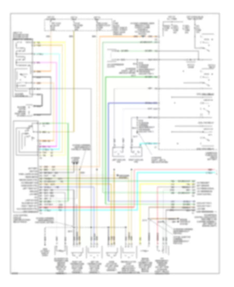
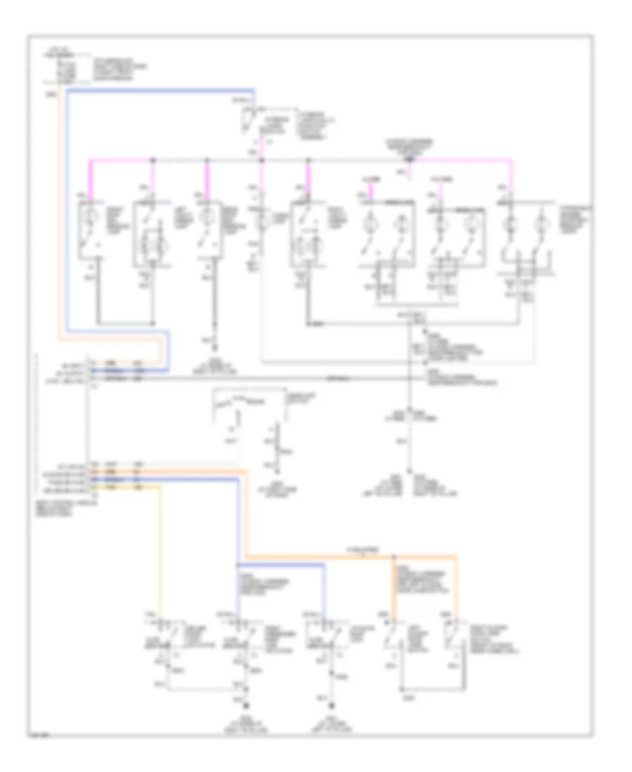
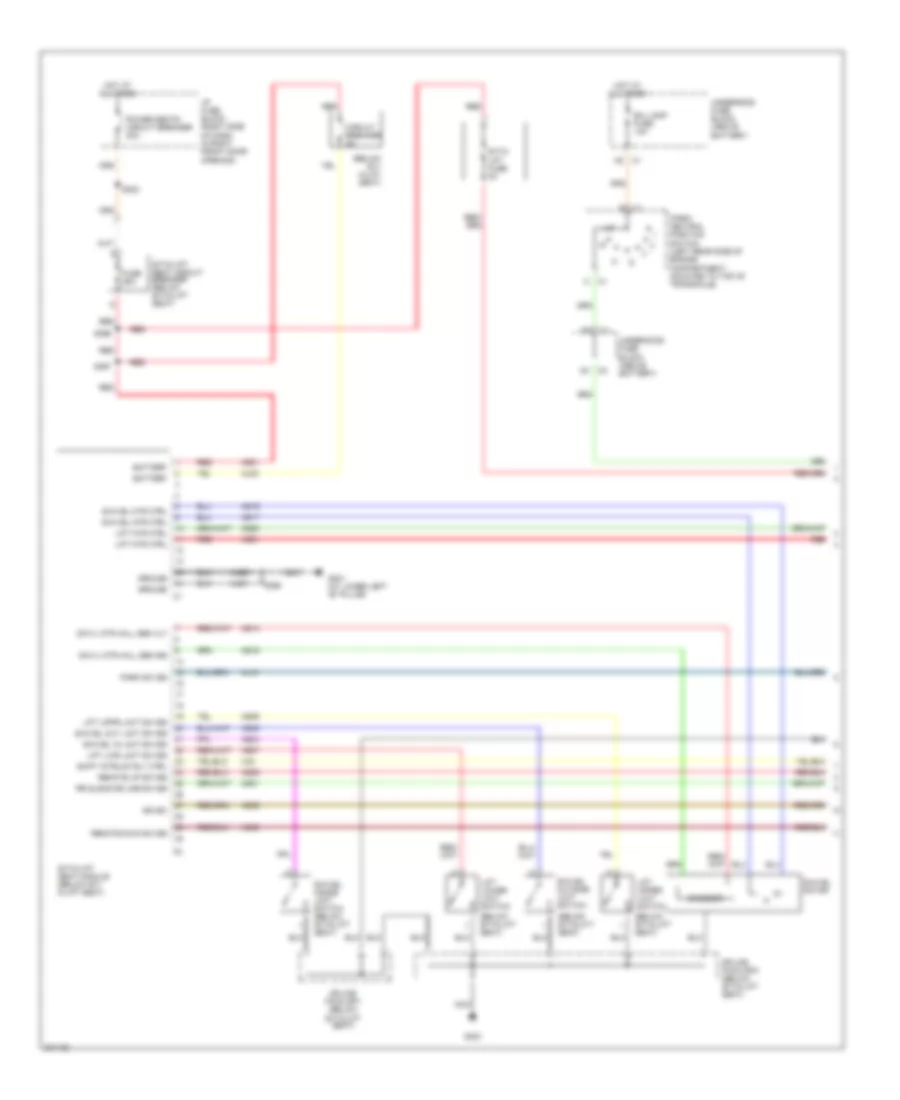
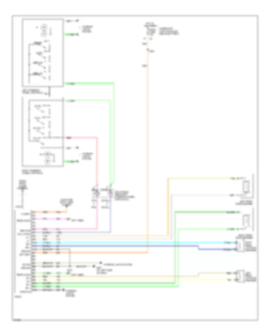
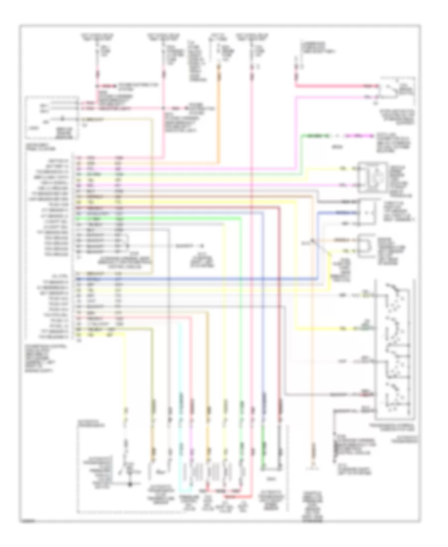
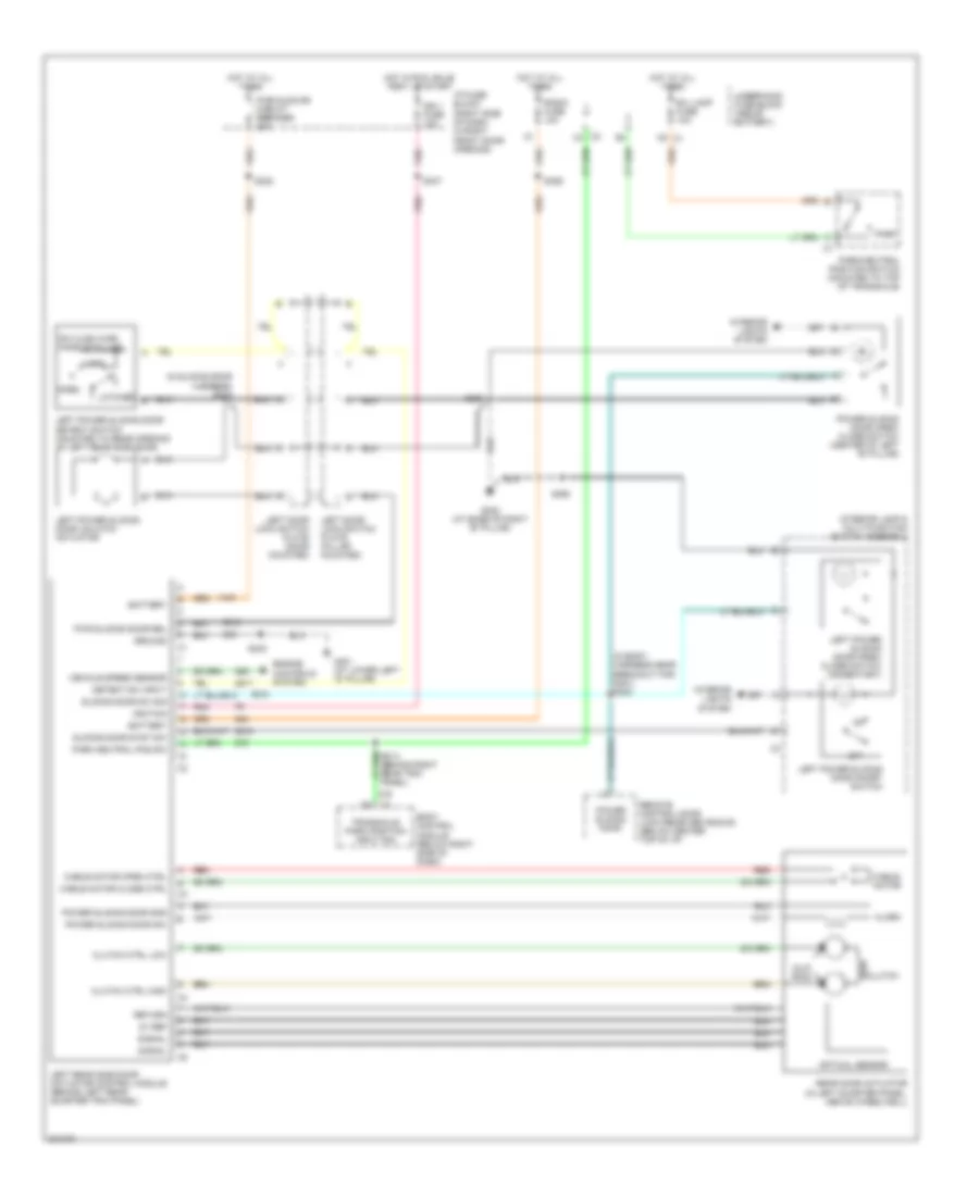
Manual A/C Wiring Diagram, with Video Entertainment (1 of 2) for Chevrolet Venture LS 2005
List of elements for Manual A/C Wiring Diagram, with Video Entertainment (1 of 2) for Chevrolet Venture LS 2005:
- (in dash harness, near breakout for cigar lighter)
- (in dash harness, near breakout for relay center)
- (in dash harness, near breakout for window wiper/ washer & multifunction switch) s202
- (in engine compt, left & above starter)
- (in engine harness, near breakout for pcm)
- (in fuel injector harness, near breakout for c102)
- (next to blower motor) blower motor resistor assembly
- +5v
- +5v reference
- A/c clu diode
- A/c clu fuse 10a
- A/c clu relay
- A/c compressor clutch
- A/c press signal
- A/c refrigerant pressure sensor (on left side of engine compt, below accumulator)
- A/c request
- A/c request sig
- A10
- Aux mode door ctrl
- Battery
- Blower motor (behind right side of dash)
- Blower motor relay
- Blower sw off
- C10
- C11
- Comp control
- Cool fan 1 fuse 30a
- Cool fan 2 fuse 30a
- Cool fan 1 relay
- Cool fan 2 relay
- Cool fan relay
- Coolant fan 1
- Coolant fan 2
- Defogger system
- Drl/hvac/ temp/htd st fuse 10a
- Ect sensor
- Engine controls system
- Engine coolant temperature (ect) sensor (on top left rear of engine)
- Evaporative temperature sensor (behind center of dash, on hvac assembly)
- F11
- Frt hvac hi blwr c.b. 30a
- G117
- G200 (at right side of dash)
- Ground
- Hot at all times
- Hot in run
- Hot in run, bulb test or start
- Hvac blower fuse 25a
- Hvac control module (center of dash, below radio)
- I/p fuse block (right side of dash, in right front door opening)
- Ignition
- Interior lights system
- Lamp dim sig
- Left air temperature actuator (left side of hvac assembly)
- Left cooling fan
- Left temp act
- Low ref
- Low reference
- Mode actuator (on left side of hvac assembly)
- Mode door ctrl
- Nca
- Off
- Park lamps on sig
- Powertrain control module (pcm) (secured in air cleaner assembly, left front of engine compt)
- Radio fuse 10a
- Rear defog
- Recirc door ctrl
- Recirculation inlet actuator (behind right side of dash, above blower motor)
- Red
- Right air temperature actuator (right side of hvac assembly)
- Right cooling fan
- Right temp act
- S105 (in engine harness, near breakout for engine coolant fan 1)
- S110
- S167
- S213
- S264
- Tan
- Underhood fuse block (above battery)
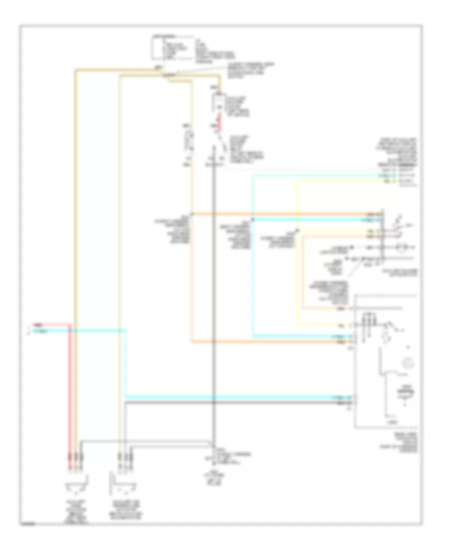
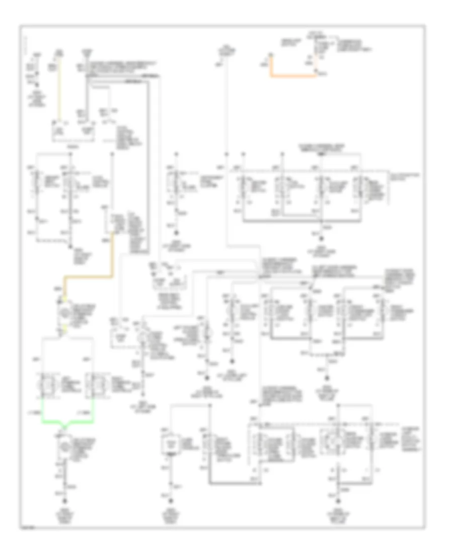
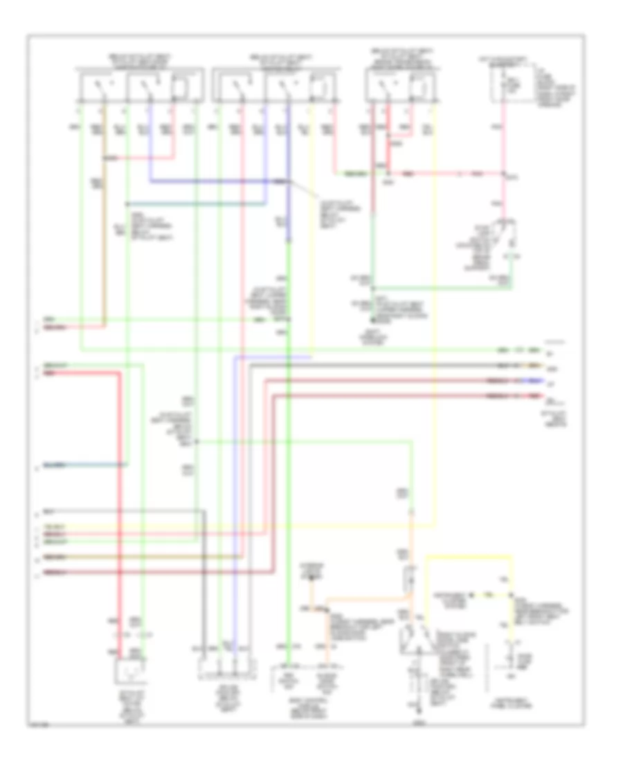
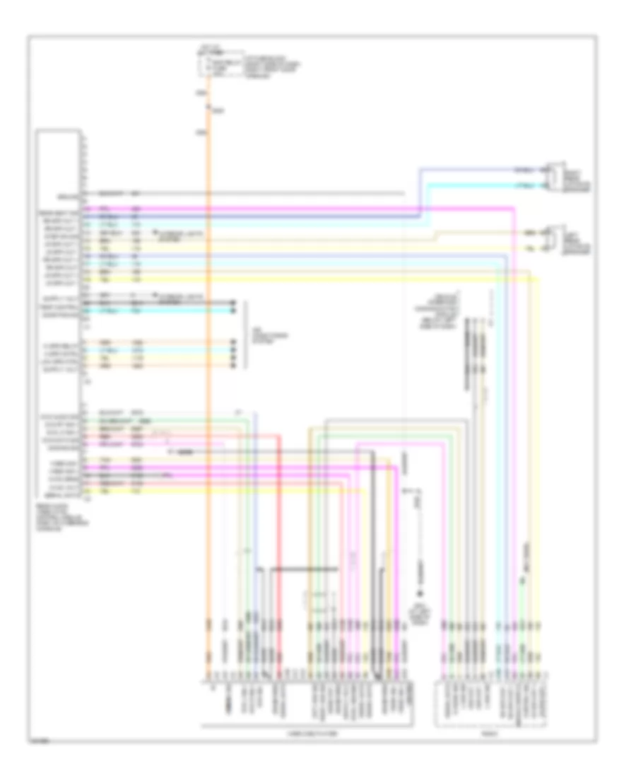
Manual A/C Wiring Diagram, with Video Entertainment (2 of 2) for Chevrolet Venture LS 2005
List of elements for Manual A/C Wiring Diagram, with Video Entertainment (2 of 2) for Chevrolet Venture LS 2005:
- (in body harness, near breakout for left sliding door jamb switch)
- (in dash harness, near breakout for window wiper/ washer & multifunction switch)
- (part of auxiliary heater-a/c module, to rear of auxiliary blower motor) auxiliary blower motor resistor assembly
- Auxiliary air temperature actuator (below auxiliary blower motor)
- Auxiliary blower motor (left rear of vehicle)
- Auxiliary blower motor relay (at left rear of vehicle, on rear wheelwell)
- Auxiliary blower motor switch
- Auxiliary mode actuator (behind left rear wheelwell)
- G200 (at right side of dash)
- G401 (at lower
- Hot in run
- I/p fuse block (right side of dash, in right front door opening)
- Interior lights system
- Left "d" pillar)
- Logic
- Rear video/ audio/hvac module (part of overhead console)
- Red
- Rr hvac/ temp cont fuse 25a
- S230
- S339 (in body harness, near break- out for g301)
- S341 (body harness, near break- out for radio rear speaker amplifier)
- S343 (in body harness, near break- out for radio rear speaker amplifier)
- S345
- Temp control
- Wheelwell)
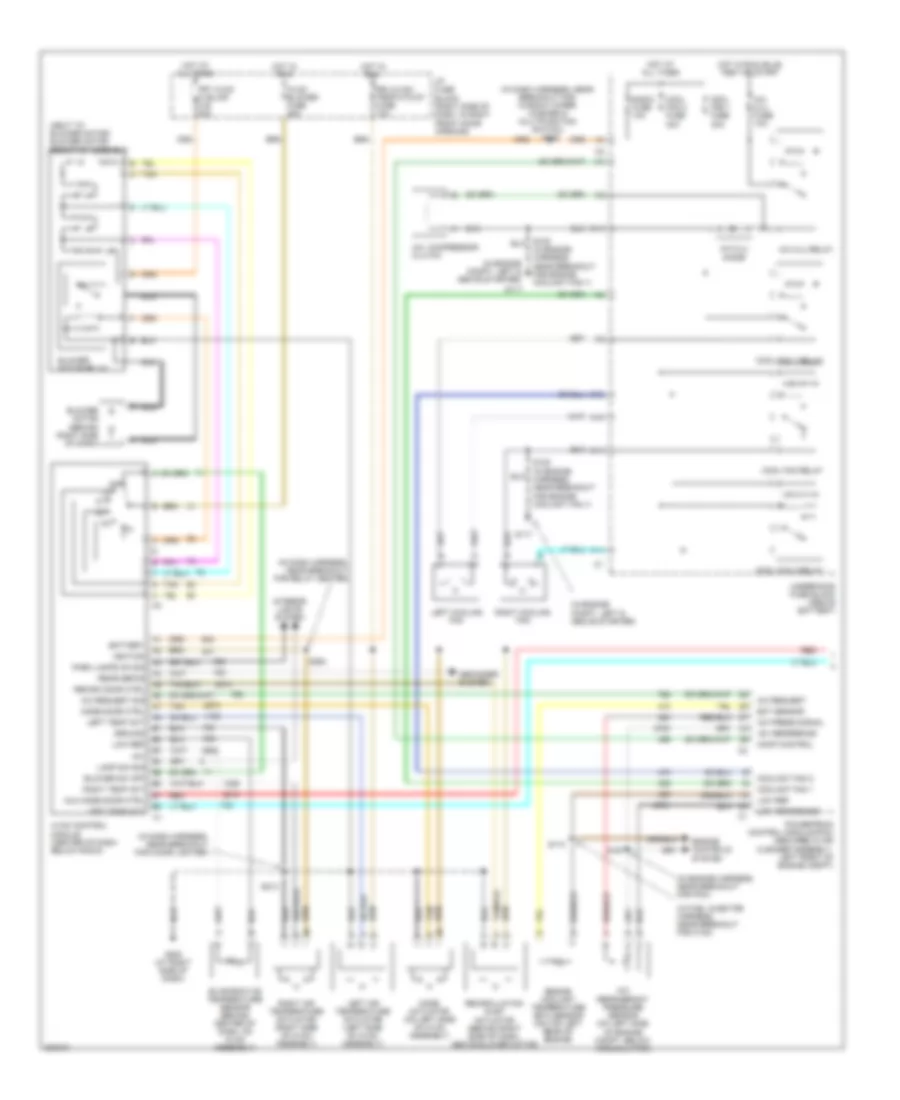
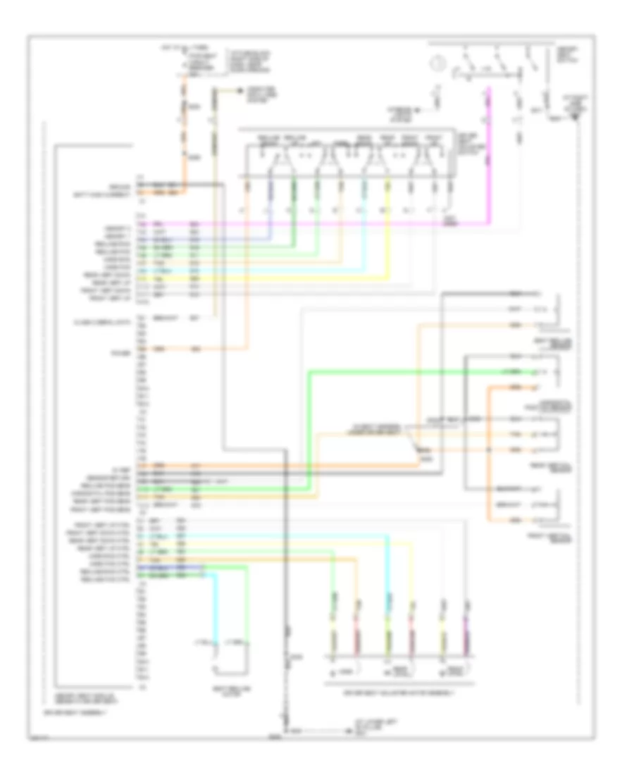
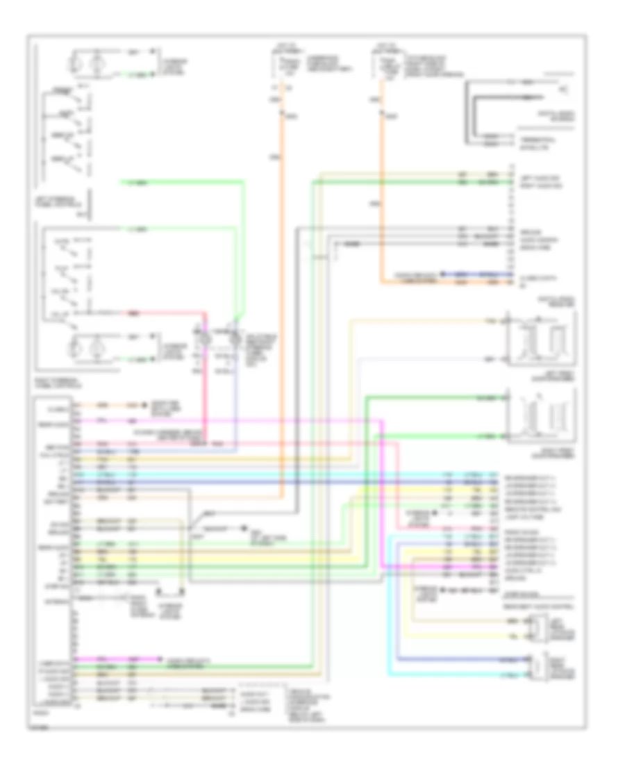
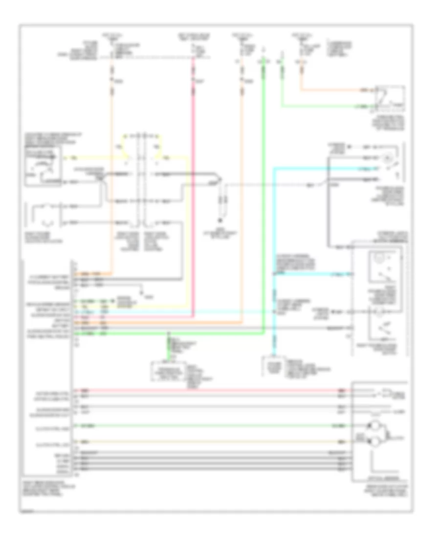
Manual A/C Wiring Diagram, without Video Entertainment (1 of 2) for Chevrolet Venture LS 2005
List of elements for Manual A/C Wiring Diagram, without Video Entertainment (1 of 2) for Chevrolet Venture LS 2005:
- (in dash harness, near breakout for cigar lighter)
- (in dash harness, near breakout for relay center)
- (in dash harness, near breakout for window wiper/ washer & multifunction switch) s202
- (in engine compt, left & above starter)
- (in engine harness, near breakout for pcm)
- (in fuel injector harness, near breakout for c102)
- (next to blower motor) blower motor resistor assembly
- +5v
- +5v reference
- A/c compressor clutch
- A/c clu diode
- A/c clu fuse 10a
- A/c clu relay
- A/c press signal
- A/c refrigerant pressure sensor (on left side of engine compt, below accumulator)
- A/c request
- A/c request sig
- A10
- Aux mode door ctrl
- Battery
- Blower motor (behind right side of dash)
- Blower motor relay
- Blower sw off
- C10
- C11
- Comp control
- Cool fan 1 fuse 30a
- Cool fan 2 fuse 30a
- Cool fan 1 relay
- Cool fan 2 relay
- Cool fan relay
- Coolant fan 1
- Coolant fan 2
- Defogger system
- Drl/hvac/ temp/htd st fuse 10a
- Ect sensor
- Engine controls system
- Engine coolant temperature (ect) sensor (on top left rear of engine)
- Evaporative temperature sensor (behind center of dash, on hvac assembly)
- F11
- Frt hvac hi blwr c.b. 30a
- G117
- G200 (at right side of dash)
- Ground
- Hot at all times
- Hot in run
- Hot in run, bulb test or start
- Hvac blower fuse 25a
- Hvac control module (center of dash, below radio)
- I/p fuse block (right side of dash, in right front door opening)
- Ignition
- Interior lights system
- Lamp dim sig
- Left air temperature actuator (left side of hvac assembly)
- Left cooling fan
- Left temp act
- Low ref
- Low reference
- Mode actuator (on left side of hvac assembly)
- Mode door ctrl
- Nca
- Off
- Park lamps on sig
- Powertrain control module (pcm) (secured in air cleaner assembly, left front of engine compt)
- Radio fuse 10a
- Rear defog
- Recirc door ctrl
- Recirculation inlet actuator (behind right side of dash, above blower motor)
- Red
- Right air temperature actuator (right side of hvac assembly)
- Right cooling fan
- Right temp act
- S105 (in engine harness, near breakout for engine coolant fan 1)
- S110
- S167
- S213
- S264
- Tan
- Underhood fuse block (above battery)
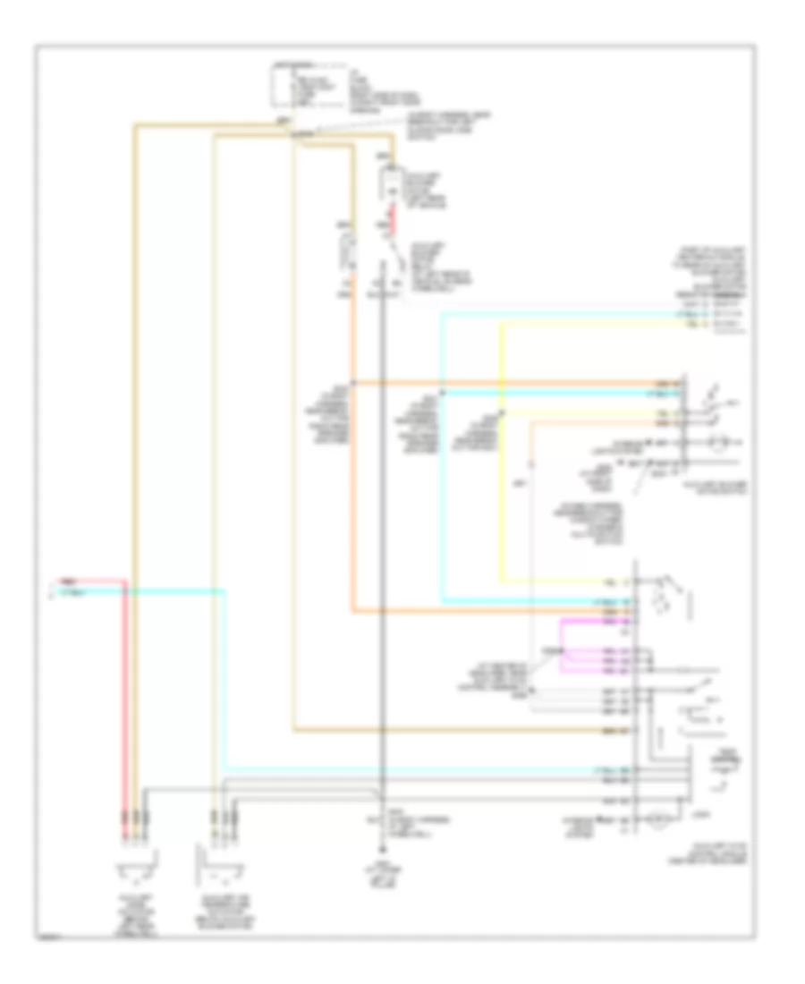
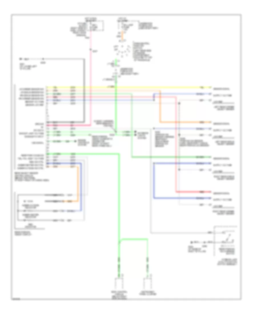
Manual A/C Wiring Diagram, without Video Entertainment (2 of 2) for Chevrolet Venture LS 2005
List of elements for Manual A/C Wiring Diagram, without Video Entertainment (2 of 2) for Chevrolet Venture LS 2005:
- (at center of headliner, near auxiliary hvac control assembly) s396
- (in body harness, near breakout for left sliding door jamb switch)
- (in dash harness, near breakout for window wiper/ washer & multifunction switch)
- (part of auxiliary heater-a/c module, to rear of auxiliary blower motor) auxiliary blower motor resistor assembly
- Auxiliary air temperature actuator (below auxiliary blower motor)
- Auxiliary blower motor (left rear of vehicle)
- Auxiliary blower motor relay (at left rear of vehicle, on rear wheelwell)
- Auxiliary blower motor switch
- Auxiliary hvac control module (center of headliner)
- Auxiliary mode actuator (behind left rear wheelwell)
- G200 (at right side of dash)
- G401 (at lower
- Hot in run
- I/p fuse block (right side of dash, in right front door opening)
- Interior lights system
- Left "d" pillar)
- Logic
- Red
- Rr hvac/ temp cont fuse 25a
- S230
- S339 (in body harness, near break- out for g301)
- S341 (in body harness, near break- out for radio rear speaker amplifier)
- S343 (in body harness, near break- out for radio rear speaker amplifier)
- S345
- S394
- S403 (in body harness, at left wheelwell)
- Temp control
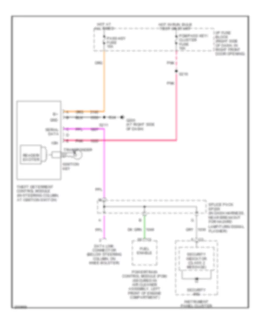
ANTI-LOCK BRAKES
Anti-lock Brakes Wiring Diagram for Chevrolet Venture LS 2005
List of elements for Anti-lock Brakes Wiring Diagram for Chevrolet Venture LS 2005:
- (at right side of dash) g200
- A10
- A11
- Anti-lock brake ind
- B10
- B11
- Battery
- Brake fluid level switch (on right side of brake fluid reservoir)
- Brake ind
- Brake pressure modulator valve (bpmv) (left side of engine compartment)
- C10
- C11
- Data link connector (dlc) (below steering column, on knee bolster)
- Delivered torque
- Desired torque
- Electronic brake control module (ebcm) (at lower left side of engine compt)
- G114 (in engine compt, left & above starter)
- G200 (at right side of dash)
- Ground
- Hot at all times
- Hot in run, bulb test or start
- Ignition
- Instrument panel cluster
- Interior lights system
- Ip fuse block (right side of dash, in right front door opening)
- Left front wheel spd (hi)
- Left front wheel spd (lo)
- Left front wheel speed sensor
- Left rear wheel spd (hi)
- Left rear wheel spd (lo)
- Left rear wheel speed sensor
- Nca
- Pcm/abs fuse 10a
- Pnk
- Powertrain control module (pcm) (secured in air cleaner assembly, left front of engine compt)
- Pump motor
- Rear fog lamp/ tcs switch
- Rear window wiper/ washer multifunction switch
- Red
- Right front wheel spd (hi)
- Right front wheel spd (lo)
- Right front wheel speed sensor
- Right rear wheel spd (hi)
- Right rear wheel spd (lo)
- Right rear wheel speed sensor
- S108
- S205 (in dash harness, near breakout for harzard lamp/ turn signal flasher)
- S230
- S242
- Serial data sig
- Service traction system
- Sp205
- Stop lamp sw out
- Stoplamp fuse 15a
- Stoplamp switch (mounted to brake pedal support)
- Tan
- Trac off ind
- Traction active
- Traction ctrl on/off sig
- Underhood fuse block (above battery)
- Vent tube
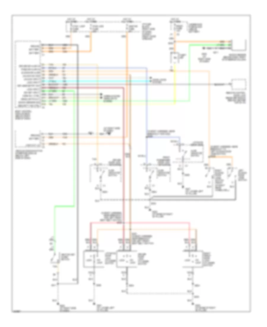
ANTI-THEFT
Forced Entry Wiring Diagram for Chevrolet Venture LS 2005
List of elements for Forced Entry Wiring Diagram for Chevrolet Venture LS 2005:
- (at right side of dash)
- (in body harness, near breakout for c302) s309
- (in body harness, near breakout for left front seat belt switch) s323
- (in body harness, near breakout to left sliding door jamb switch) s325
- Ajar indicator switch
- Battery
- Body control module (bcm) (below right side of dash)
- C11
- Ctsy lamp fuse 10a
- D10
- D11
- D14
- D15
- Door locks system
- Driver door lock actuator
- Driver door lock cylinder switch
- Driver dr ajar in
- Front passenger door lock actuator
- G200
- G200 (at right side of dash)
- G302 (at base of right "b" pillar)
- G401 (at lower left "d" pillar)
- Ground
- Headlights out
- Headlights system
- Horn rly ctrl
- Horns system
- Hot at all times
- I/p fuse block (right side of dash, in right front door opening)
- Ign key input
- Ignition key alarm switch
- Keyless entry sw
- Left sliding door jamb switch
- Liftgate door lock
- Liftgate door lock cylinder switch
- Lock
- Lock input
- Lock out lo
- Nca
- Onstar fuse 5a
- Pass dr ajar in
- Pwr lock fuse 20a
- Radio fuse 10a
- Remote control door lock receiver (rcdlr) (behind center top of i/p)
- Right front door lock cylinder switch
- Right sliding door jamb switch (front of right rear wheelwell)
- S202
- S211
- S303
- S460
- S504
- S604
- Security ind ctrl
- Shock sensor (behind dash, right of steering column)
- Shock sensor sig
- Sliding dr ajar
- Tan
- Theft led
- Un- lock
- Underhood fuse block (above battery)
- Unlock input
- Unlock sw sig
- Vehicle communication interface module (below left side of dash)
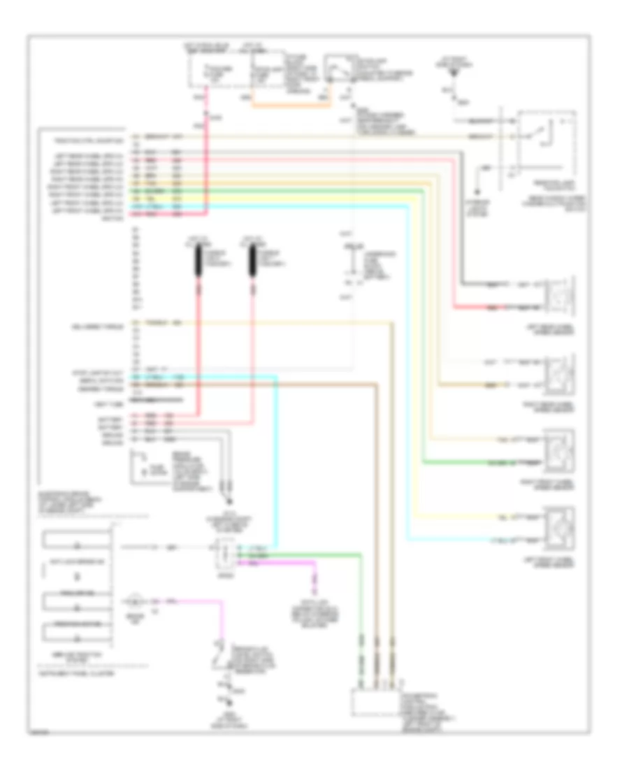
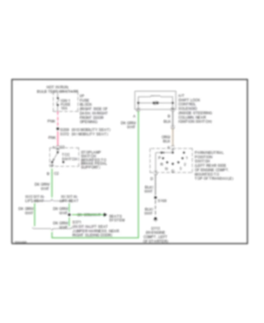
Pass-Key Wiring Diagram for Chevrolet Venture LS 2005
List of elements for Pass-Key Wiring Diagram for Chevrolet Venture LS 2005:
- Data link connector (below steering column, on knee bolster)
- Fuel enable
- G200 (at right side of dash)
- Gnd
- Hot at all times
- Hot in run, bulb test or start
- I/p fuse block (right side of dash, in right front door opening)
- Ign
- Ignition key
- Instrument panel cluster
- Lamp/turn signal flasher)
- Pass-key fuse 10a
- Pcm/pass key/ cluster fuse 10a
- Pnk
- Powertrain control module (pcm) (secured in air cleaner assembly, left front of engine compartment)
- Reader/ exciter
- S210
- S211
- Security ind
- Security indicator (class 2 message)
- Serial data
- Splice pack sp205 (in dash harness, near breakout for hazard
- Theft deterrent control module (in steering column, at ignition switch)
- Transponder
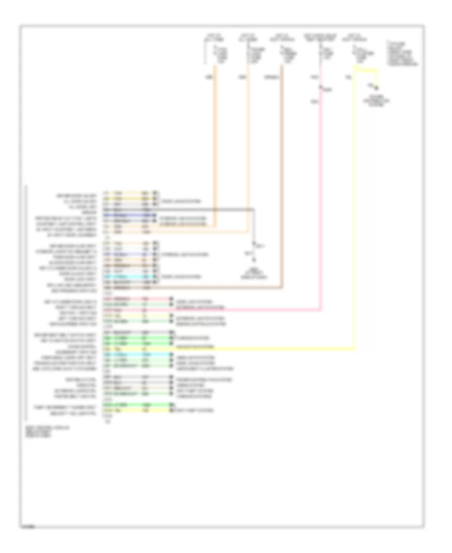
BODY CONTROL MODULES
Body Control Modules Wiring Diagram for Chevrolet Venture LS 2005
List of elements for Body Control Modules Wiring Diagram for Chevrolet Venture LS 2005:
- Accessory input sig
- All door lock
- All door unlock
- Anti-theft system
- B+ input courtesy lights/bcm
- B+ input door locks/bcm
- Bcm prgrm fuse 10a
- Bcm program input sig
- Body control module (below right side of dash)
- C10
- C11
- C12
- C13
- C14
- C15
- C16
- Chime control
- Courtesy lamp control input
- Ctsy lamp fuse 10a
- D10
- D11
- D12
- D13
- D14
- D15
- D16
- Door lock input
- Door lock system
- Door locks system
- Door unlock input
- Driver door ajar input
- Driver door unlock
- Driver seat belt switch input
- Engine controls system
- Exterior lamps ctrl
- Exterior lights system
- Fasten belt ind ctrl
- G200 (at right side of dash)
- Ground
- Headlights system
- Horn ctrl
- Horns system
- Hot at all times
- Hot in accy or run
- Hot in run, bulb test or start
- I/p fuse block (right side of dash, in right front door opening)
- Ign 1 fuse 10a
- Ignition 1 input sig
- Instrument cluster system
- Interior lamps "on" request in
- Interior lights system
- Key cylinder door lock in
- Key cylinder door unlock in
- Key in ignition switch input
- Left turn sig input
- Mall/ cluster fuse 10a
- Navigation system
- Park/head lamps "off" input
- Pass door ajar input
- Pnk
- Power distribution system
- Power lock fuse 20a
- Protected b+ out ctsy lights
- Rap relay ctrl
- Rfa link (keyless entry)
- Right turn sig input
- S209
- S211
- Sec. sys warn away ctd disarm
- Security ind lamp ctrl
- Sliding door ajar input
- Tan
- Theft deterrent tamper input
- Transaxle park position input
- Vehicle speed input sig
- Warning system
- Warning systems
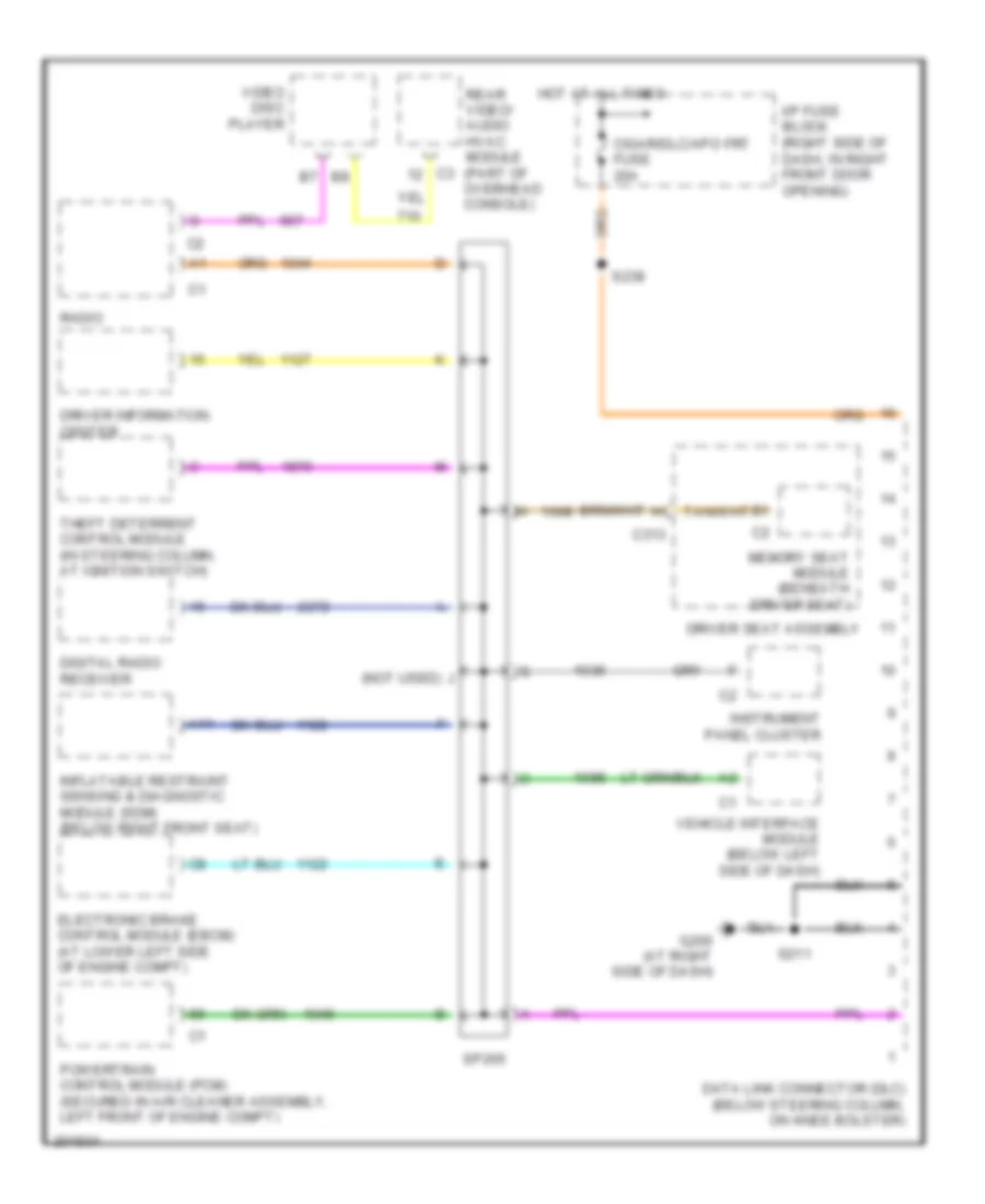
COMPUTER DATA LINES
Computer Data Lines Wiring Diagram for Chevrolet Venture LS 2005
List of elements for Computer Data Lines Wiring Diagram for Chevrolet Venture LS 2005:
- A11
- C313
- Cigar/dlc/apo frt fuse 20a
- Data link connector (dlc) (below steering column, on knee bolster)
- Digital radio receiver
- Driver information center
- Driver seat assembly
- Electronic brake control module (ebcm) (at lower left side of engine compt)
- G200 (at right side of dash)
- Hot at all times
- I/p fuse block (right side of dash, in right front door opening)
- Inflatable restraint sensing & diagnostic module (sdm) (below right front seat)
- Instrument panel cluster
- J (not used)
- Memory seat module (beneath driver seat)
- Powertrain control module (pcm) (secured in air cleaner assembly, left front of engine compt)
- Radio
- Rear video/ audio hvac module (part of overhead console)
- S211
- S238
- Sp205
- Theft deterrent control module (in steering column, at ignition switch)
- Vehicle interface module (below left side of dash)
- Video disc player
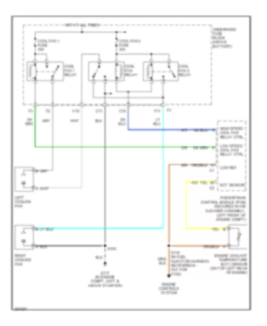
COOLING FAN
Cooling Fan Wiring Diagram for Chevrolet Venture LS 2005
List of elements for Cooling Fan Wiring Diagram for Chevrolet Venture LS 2005:
- A10
- C10
- C11
- Cool fan 1 fuse 30a
- Cool fan 1 relay
- Cool fan 2 fuse 30a
- Cool fan 2 relay
- Cool fan relay
- Ect sensor
- Engine controls system
- Engine coolant temperature (ect) sensor (on top left rear of engine)
- F11
- G117 (in engine compt, left & above starter)
- High speed cool fan relay ctrl
- Hot at all times
- Left cooling fan
- Low ref
- Low speed cool fan relay ctrl
- Powertrain control module (pcm) (secured in air cleaner assembly, left front of engine compt)
- Right cooling fan
- S105
- S110 (in fuel injector harness, near break- out for c102)
- Underhood fuse block (above battery)
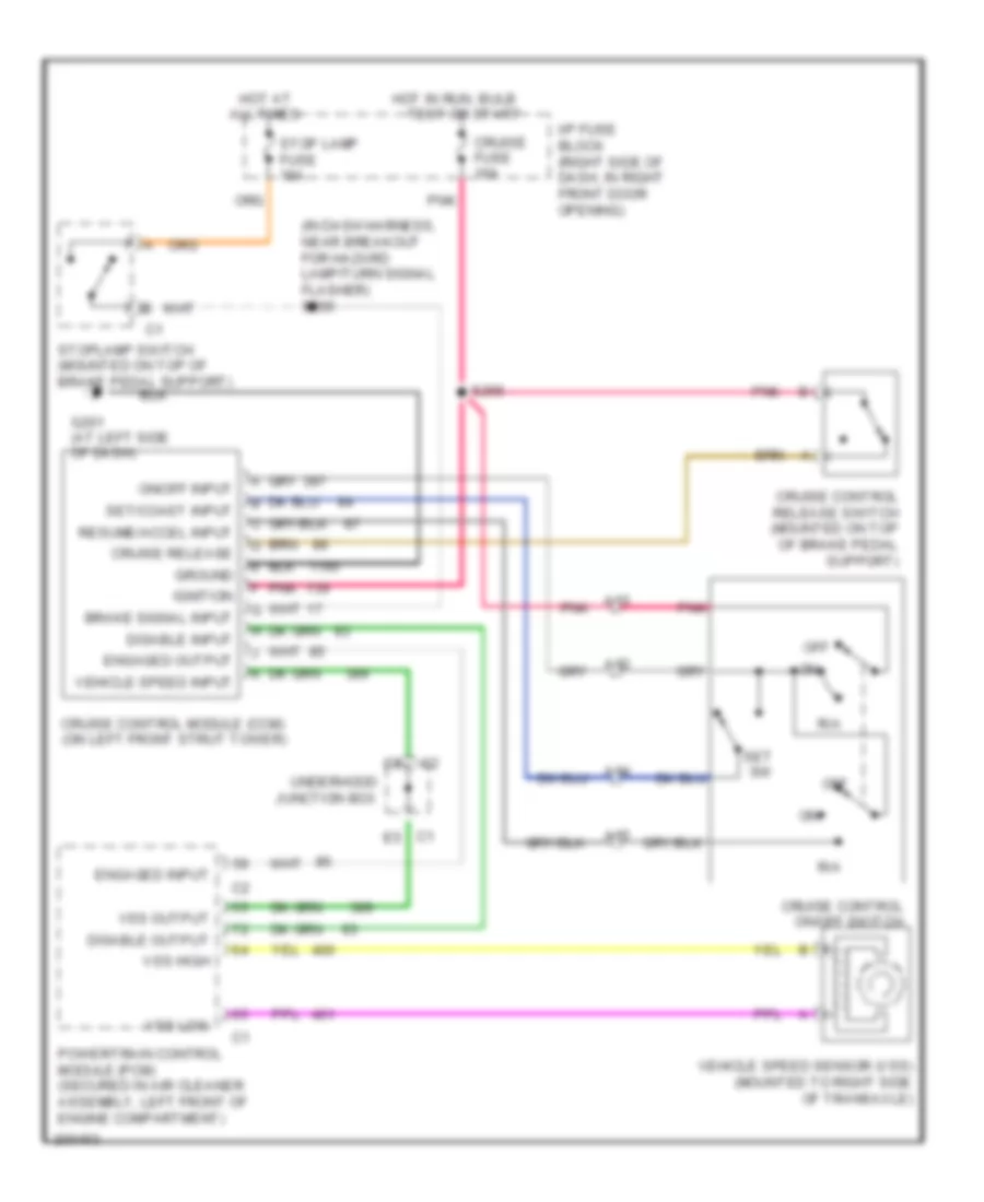
CRUISE CONTROL
Cruise Control Wiring Diagram for Chevrolet Venture LS 2005
List of elements for Cruise Control Wiring Diagram for Chevrolet Venture LS 2005:
- (in dash harness, near breakout for hazard lamp/turn signal flasher) s205
- A12
- A13
- A14
- A15
- All times
- Brake signal input
- C1 e5
- Cruise control module (ccm) (on left front strut tower)
- Cruise control on/off switch
- Cruise control release switch (mounted on top of brake pedal support)
- Cruise fuse 10a
- Cruise release
- Disable input
- Disable output
- Engaged input
- Engaged output
- G201 (at left side of dash)
- Ground
- Hot at
- Hot in run, bulb
- I/p fuse block (right side of dash, in right front door opening)
- Ignition
- Off
- On/off input
- Pnk
- Powertrain control module (pcm) (secured in air cleaner assembly, left front of engine compartment)
- R/a
- Resume/accel input
- S266
- Set sw
- Set/coast input
- Stop lamp fuse 15a
- Stoplamp switch (mounted on top of brake pedal support)
- Test or start
- Underhood junction box
- Vehicle speed input
- Vehicle speed sensor (vss) (mounted to right side of transaxle)
- Vss high
- Vss low
- Vss output
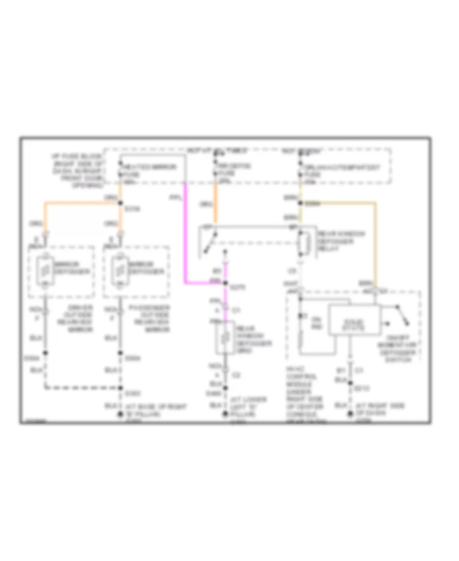
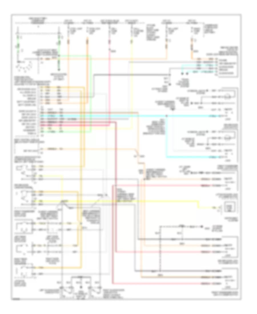
DEFOGGERS
Defoggers Wiring Diagram for Chevrolet Venture LS 2005
List of elements for Defoggers Wiring Diagram for Chevrolet Venture LS 2005:
- (at lower left "d" pillar) g401
- (at right side of dash) g200
- Driver outside rearview mirror
- Drl/hvac/temp/htdst fuse 10a
- E nca
- Heated mirror fuse 10a
- Hot at all times
- Hot in run
- Hvac control module (under right side of center console, near dash)
- I/p fuse block (right side of dash, in right front door opening)
- Mirror defogger
- Nca
- On ind
- On/off momentary defogger switch
- Passenger outside rearview mirror
- Rear window defogger grid
- Rear window defogger relay
- Rr defog fuse 30a
- S213
- S264
- S275
- S303
- S318
- S460
- S504
- S604
- Solid state
ELECTRONIC SUSPENSION
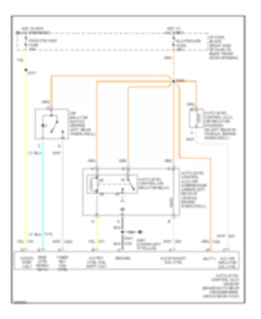
Electronic Suspension Wiring Diagram, with Inflator for Chevrolet Venture LS 2005
List of elements for Electronic Suspension Wiring Diagram, with Inflator for Chevrolet Venture LS 2005:
- Acces- sory volt
- Air inflator switch (behind left rear wheelwell)
- Alc air inflator sol ctrl
- Alc exhaust sol ctrl
- Alc rly ctrl coil supp volt
- Auto level control (alc) air compressor (under left rear of vehicle, behind wheelwell)
- Auto level control (alc) air inflator solenoid (in left rear of vehicle, behind wheelwell)
- Auto level control (alc) sensor (mounted to rear crossmenber, above rear axle)
- Auto level control air inflator relay
- Batt+
- Elc/trailer fuse 25a
- G401 (lower left "d" pillar)
- Ground
- Hot at all times
- Hot w/ rap relay energized
- I/p fuse block (right side of dash, in right front door opening)
- Pwr otr vent fuse 10a
- Ride ctrl serial data
- S317
- S441
- S445
- Timer rly coil ctrl
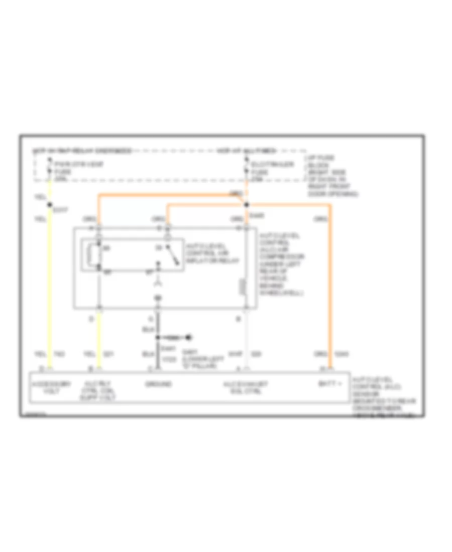
Electronic Suspension Wiring Diagram, without Inflator for Chevrolet Venture LS 2005
List of elements for Electronic Suspension Wiring Diagram, without Inflator for Chevrolet Venture LS 2005:
- Accessory volt
- Alc exhaust sol ctrl
- Alc rly ctrl coil supp volt
- Auto level control (alc) air compressor (under left rear of vehicle, behind wheelwell)
- Auto level control (alc) sensor (mounted to rear crossmenber, above rear axle)
- Auto level control air inflator relay
- Batt +
- Elc/trailer fuse 25a
- G401 (lower left "d" pillar)
- Ground
- Hot at all times
- Hot w/ rap relay energized
- I/p fuse block (right side of dash, in right front door opening)
- Pwr otr vent fuse 10a
- S317
ENGINE PERFORMANCE
3.4L VIN E
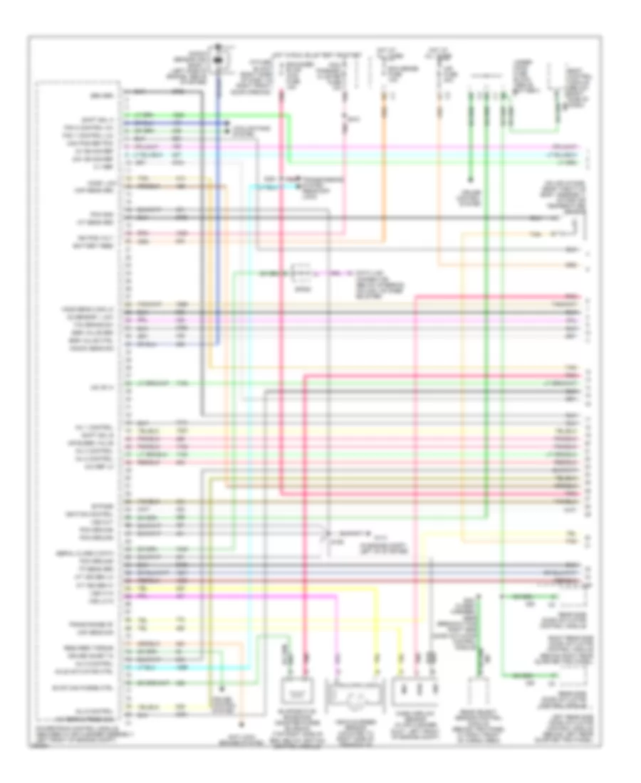
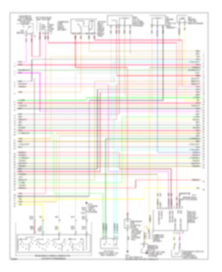
3.4L VIN E, Engine Performance Wiring Diagram (1 of 4) for Chevrolet Venture LS 2005
List of elements for 3.4L VIN E, Engine Performance Wiring Diagram (1 of 4) for Chevrolet Venture LS 2005:
- (3x) ref lo
- (in engine compt, left of starter)
- (on air intake, near throttle body assembly) intake air temperature sensor
- 24x ign sig ref
- 3x ign sig ref
- 5 v ref
- A/c refrig press sig
- A/t iss sen hi
- A/t iss sen lo
- Air bleed valve
- Air fuse 30a
- Anti-lock brakes system
- Axle actuator ctrl
- Battery feed
- Body control module (below right side of dash)
- Bypass
- C15
- Cam pos ref pcm
- Cooling fans system
- Cruise control system
- Cruise inhibit in
- Data link connector (below steering column, on knee bolster)
- Ecm sense fuse 10a
- Egr valve ctrl
- Egr valve grd
- Enhanced evap/ awd fuse 15a
- Evap can purge ctrl
- Evaporative emissions canister purge solenoid (top right side of eng, below ignition control module)
- Fan 1 control (lo)
- Fan 2 control (hi)
- G113
- Gnd
- Ho2s sens 2 sig lo
- Ho2s1 low
- Hot at all times
- Hot in run, bulb test or start
- I/p fuse block (right side of dash, in right front door opening)
- Iac "b" hi
- Iat sens grd
- Ign pos volt
- Ignition control
- Inj 1 control
- Inj 2 control
- Inj 3 control
- Inj 5 control
- Inj 6 control
- Knock sens sig
- Knock sensor (ks) bank 1 (left side of engine, above starter)
- Left rear side door actuator control module (behind left rear quarter trim panel)
- Maf
- Maf sens sig
- Map sens grd
- Mass airflow sensor (in air cleaner duct, left front of engine compt)
- O2 sensor 1 low
- Pcm gnd
- Pcm ground
- Pcm/ passkey cluster fuse 10a
- Pnk
- Powertrain control module (secured in air cleaner assembly, left front of engine compt)
- Pwr
- Rear object sensor control module (behind trim panel at right front of cargo area)
- Rear side door actuator control module
- Required torque
- Right rear side door actuator control module (behind right rear quarter trim panel)
- S106
- S210
- S321 (in body harness, near breakout for right side door actuator control module)
- S391
- Sen grd
- Serial class 2 data
- Shift sol a
- Shift sol b
- Sp205
- Tan
- Tcc brake sw
- Tp sens grd
- Trans range "b"
- Transmissions system (rear diff lock)
- Under- hood fuse block (above battery)
- Vehicle speed sensor (mounted to right side of transaxle)
- Vss hi in
- Vss lo in
- Vss out
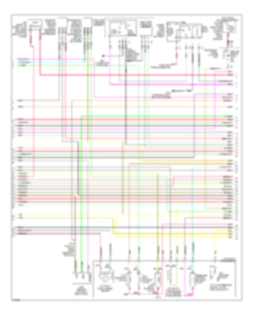
3.4L VIN E, Engine Performance Wiring Diagram (2 of 4) for Chevrolet Venture LS 2005
List of elements for 3.4L VIN E, Engine Performance Wiring Diagram (2 of 4) for Chevrolet Venture LS 2005:
- (fuel sender harn, near breakout for c305) s329
- 1-2 shift solenoid valve
- 2-3 shift solenoid valve
- 5v ref
- A fuel pump prime connector
- A red
- A/t fluid pressure manual valve position switch
- A/t input shaft speed sensor
- Automatic transmission
- Automatic transmission fluid temper- ature sensor
- Camshaft position sensor (front of engine, nca above a/c compressor)
- Fuel level sensor
- Fuel pump
- Fuel pump & sender assembly
- Fuel pump fuse 15a
- Fuel pump relay
- Fuel tank pressure sensor
- G113 (in engine compt, left of starter)
- G301 (lower left "b" pillar)
- Hot at all times
- Hot in run, bulb test & start
- I/p fuse block (right side of dash, in right front door opening)
- Ign 1 fuse 10a
- Instrument panel cluster (ipc)
- Map
- Map sensor (top right side of eng)
- Nca
- Pnk
- Pnk j
- Pressure control solenoid valve
- Red
- Rtn
- S110 (fuel inj harn, near breakout for c102)
- S115
- S209
- Service engine soon ind (mil)
- Tan
- Tcc release switch
- Tcc solenoid valve
- Under- hood fuse block (above battery)
3.4L VIN E, Engine Performance Wiring Diagram (3 of 4) for Chevrolet Venture LS 2005
List of elements for 3.4L VIN E, Engine Performance Wiring Diagram (3 of 4) for Chevrolet Venture LS 2005:
- (3x) ref high
- (3x) ref low
- (7x) ref high
- (7x) ref low
- (engine compt, left of starter)
- (mounted on top of brake pedal support) stoplamp switch
- Air pump relay (right side of engine compt, behind horn)
- Automatic transmission
- Bypass cntrl
- C2 grd
- Crankshaft position sensor b (lower right side of engine)
- D12
- Ect sensor (top left rear of engine)
- Egr valve (on upper right rear of engine)
- Elek ign fuse 15a
- Engine oil pressure switch (lower left side of eng, above starter)
- G101 (at left front of vehicle, right of left headlight)
- G111
- G113 (in engine compt, left of starter)
- Hot in run, bulb test or start
- Iac valve (front of throttle body assembly)
- Ic cntrl
- Ign
- Ignition control module (top right side of engine)
- Pnk
- Pnk b
- Red
- Red a
- S106
- Secondary air injection pump (lower left front of engine compt, on frame rail)
- Tan
- Tcc fuse 10a
- Tcc switch
- Tp sensor (on throttle body assembly)
- Transmission internal mode switch
- Underhood fuse block (above battery)
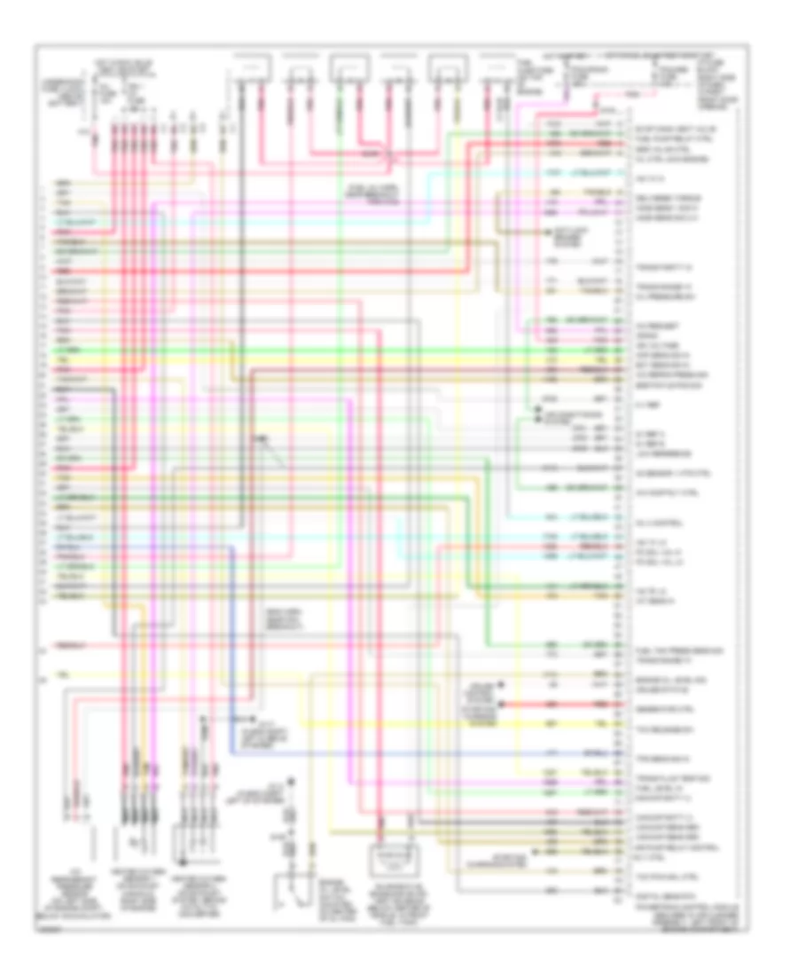
3.4L VIN E, Engine Performance Wiring Diagram (4 of 4) for Chevrolet Venture LS 2005
List of elements for 3.4L VIN E, Engine Performance Wiring Diagram (4 of 4) for Chevrolet Venture LS 2005:
- (eng harn, near pcm breakout)
- (fuel inj harn, near breakout for c102)
- (in eng compt, left & above starter)
- (in eng compt, left of starter)
- 5 v ref
- 5v ref a
- 5v ref b
- A/c comp rly ctrl
- A/c refrig press sig
- A/c refrigerant pressure sensor (on left side of engine compt, below accumulator)
- A/c request
- A12 pnk
- Air conditioning system
- Air pump relay control
- Anti-lock brakes system
- Cam/ckp batt (+)
- Cam/ckp sens grd
- Crank
- Cruise control system
- Cruise status
- D9 c3
- Delivered torque
- Digital sens rtn
- E9 c1
- Ect sens sig in
- Egr pintle pos sig
- Egr valve ctrl
- Engine oil level sig
- Engine oil level switch (mounted on center of oil pan)
- Evap cann vent valve
- Evaporative emissions (evap) vent solenoid (below center of vehicle, in front fuel tank)
- Fuel injectors (on top of engine)
- Fuel level in
- Fuel pump relay ctrl
- Fuel tnk press sens sig
- G113
- G117
- Generator ctrl
- Heated oxygen sensor 1 (on exhaust manifold, right side of engine)
- Heated oxygen sensor 2 (on exhaust system, behind catalytic converter)
- Ho2s sens 1 sig hi
- Ho2s sens sig 2 hi
- Hot in run, bulb test or start
- Hot in start
- I/p fuse block (right side of dash, in right front door opening)
- Iac "a" hi
- Iac "a" lo
- Iac "b" lo
- Iat sens in
- Ign 1 uh fuse 15a
- Ign voltage
- Inj 4 control
- Inj fuse 10a
- Low reference
- Map sens sig in
- Mil ctrl (chk engine)
- Nca
- O2 sensor 1 htr ctrl
- Oil pressure sw
- Pc sol val hi
- Pc sol val lo
- Pcm/abs fuse 10a
- Pcm/crank fuse 10a
- Pnk
- Powertrain control module (secured in air cleaner assembly, left front of engine compartment)
- Red
- Rly ctrl
- S105
- S106
- S108
- S109
- S167
- Starting/ charging system
- Tan
- Tcc pwm sol ctrl
- Tcc release sw
- Tps sens sig in
- Trans fluid temp sig
- Trans parity in
- Trans range "a"
- Trans range "c"
- Underhood fuse vlock (above battery)
EXTERIOR LIGHTS
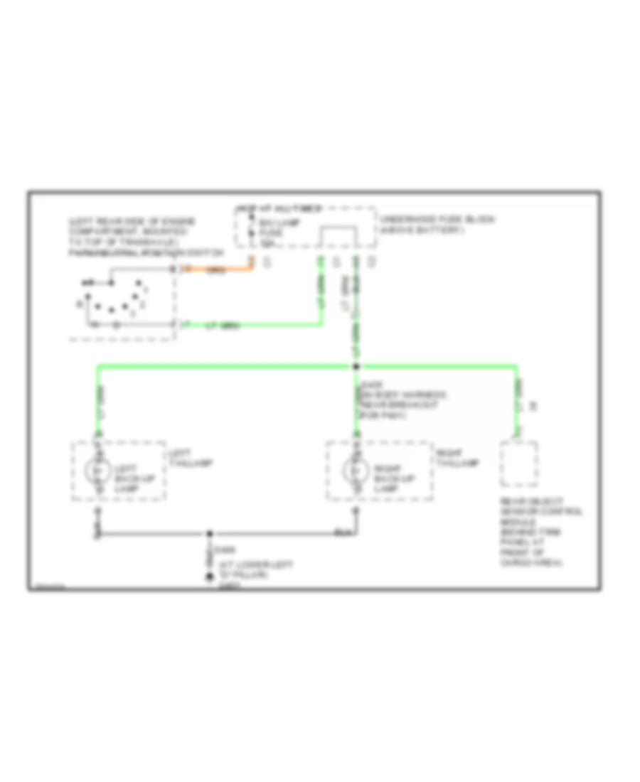
Back-up Lamps Wiring Diagram for Chevrolet Venture LS 2005
List of elements for Back-up Lamps Wiring Diagram for Chevrolet Venture LS 2005:
- (at lower left "d" pillar) g401
- (left rear side of engine compartment, mounted to top of transaxle) park/neutral position switch
- B/u lamp fuse 10a
- Hot at all times
- Left back-up lamp
- Left taillamp
- Rear object sensor control module (behind trim panel at front of cargo area)
- Right back-up lamp
- Right taillamp
- S406
- S435 (in body harness, near breakout for p401)
- Underhood fuse block (above battery)
Exterior Lamps Wiring Diagram (1 of 2) for Chevrolet Venture LS 2005
List of elements for Exterior Lamps Wiring Diagram (1 of 2) for Chevrolet Venture LS 2005:
- (in dash harness, near breakout for radio)
- Battery (b+)
- Body control module (below right side of dash)
- C12
- C14
- D11
- Daytime running lamps (drl) control module (behind dash, right side of steering column)
- Ext lamps ctrl
- G200 (at right side of dash)
- Hazard
- Hazard fuse 15a
- Head
- Headlamp switch
- Headlights system
- Hot at all times
- Hot in run, bulb test or start
- I/p fuse block (right side of dash, in right front door opening)
- Instrument panel cluster
- Left
- Lft turn in
- Lft turn out
- Lh turn ind
- Normal
- Off
- Park
- Park lp fuse 20a
- Pnk
- Rh turn ind
- Right
- Rke lamp sig
- Rt turn in
- Rt turn out
- S204
- S212
- S230
- S232 (in dash harness, near breakout for radio)
- S233 (in dash harness, near breakout for radio)
- S242
- T/sig fuse 10a
- Turn signal multi- function switch
- Turn signal/ hazard flasher module (below left side of dash, left side base of steering column)
- Underhood fuse block (above battery)
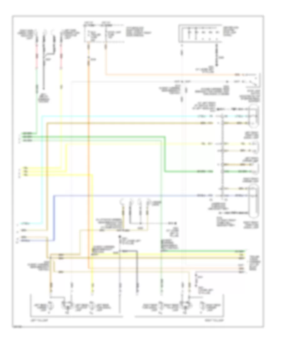
Exterior Lamps Wiring Diagram (2 of 2) for Chevrolet Venture LS 2005
List of elements for Exterior Lamps Wiring Diagram (2 of 2) for Chevrolet Venture LS 2005:
- (at left front of vehicle, right of left headlight) g101
- (in body harness, near break- out for p401) s411
- (in body harness, near breakout for c403) s431
- (in liftgate harness, near breakout for liftgate lock cylinder switch) s457
- A10
- A11
- A12
- B11
- C11
- Center high mounted stop lamp (chmsl)
- D11
- E11
- Elc/ trailer fuse 25a
- F10
- F11
- F12
- G102 (at right front wheelwell, near battery)
- G211 (below steering column)
- G401 (at lower left "d" pillar)
- G401 (lower left "d" pillar)
- Hot at all times
- I/p fuse block (right side of dash, in right front door opening)
- Left front marker lamp
- Left front park/turn signal lamp
- Left rear marker lamp
- Left rear tail/stop lamp
- Left rear turn signal lamp
- Left side mirror turn indicator light
- Left taillamp
- License lamps
- Nca
- Red
- Right front marker lamp
- Right front park/turn signal lamp
- Right rear marker lamp
- Right rear tail/stop lamp
- Right rear turn signal lamp
- Right side mirror turn indicator light nca
- Right taillamp
- S123
- S124
- S205 (in dash harness, near breakout for hazard lamp/ turn signal flasher)
- S287
- S405 (in body harness, near breakout for p401)
- S406
- S415 (in body harness, near breakout for p401)
- S441
- S445
- S460
- Stop lamp fuse 15a
- Stop lamp switch (mounted on top of brake pedal support)
- Underhood fuse block (above battery)
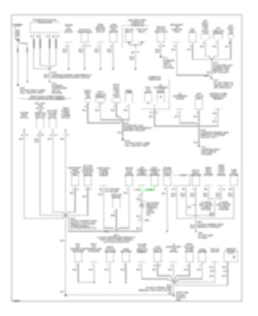
GROUND DISTRIBUTION
Ground Distribution Wiring Diagram (1 of 3) for Chevrolet Venture LS 2005
List of elements for Ground Distribution Wiring Diagram (1 of 3) for Chevrolet Venture LS 2005:
- (above battery) underhood fuse block
- (right side of dash) (partial) g200
- (w/o trailer) (w/ trailer)
- A/c compressor clutch
- A/c compressor clutch diode
- A12
- Automatic transmission
- Auxiliary blower motor switch
- B12
- Battery
- Blower motor resistor assembly
- Brake fluid level switch
- C11
- C111
- C205
- Cigar lighter
- Cool fan relay
- Cruise control module (ccm)
- Daytime running lamps (drl) control module
- Digital radio receiver
- Engine oil level switch
- Fog lamp/ tcs switch
- Front auxiliary power outlet
- Front right park/ turn signal lamp
- Fuel pump relay
- G100 (at right front wheel- well, near battery)
- G101 (at left front of vehicle, right of left headlight)
- G102 (at right front wheel- well, near battery)
- G111 (in engine compt, left of starter)
- G113 (in engine compartment, left of starter)
- G117 (in engine compt, left & above starter)
- G201 (at left side of dash)
- Headlamp switch
- Heated oxygen sensor (ho2s) sensor 2
- Heated seat switch
- Hvac control module
- I/p compartment lamp switch
- Ign main relay
- Ignition control module (icm)
- Ignition switch
- Inflatable restraint steering wheel module coil
- Instrument panel cluster (ipc)
- Left air temperature actuator
- Left cooling fan
- Left front fog lamp
- Left front park/ turn signal lamp
- Left headlamp assembly
- Left horn
- Left steering wheel controls
- Mass airflow (maf) sensor
- Mode actuator
- Nca
- Or rear fog lamp/ tcs switch
- Park/ neutral position switch
- Powertrain control module (pcm)
- Radio
- Rear seat audio control
- Rear video/ audio/ hvac module
- Rear window wiper/ washer switch
- Rear window wiper/washer & multi-function switch assembly
- Recir- culation actuator
- Right air temperature actuator
- Right front fog lamp
- Right headlamp assembly
- Right horn
- Right steering wheel controls
- S105 (in engine harness, near breakout for engine coolant fan 1)
- S106 (in engine harness, near breakout for powertrain control module)
- S123 (in forward light harness, near breakout for right foglight)
- S213 (in dash harness, near breakout for cigar lighter)
- S230 (in dash harness, near breakout for window wiper/washer & multifunction switch)
- S242 (in dash harness, near breakout for window wiper/washer & multifunction switch)
- Secondary air injection pump
- Steering column
- Turn signal/ hazard flasher module
- U2k
- Underhood fuse block
- Video disc player
- W/ rear seat enter- tainment package
- W/o rear seat enter- tainment package
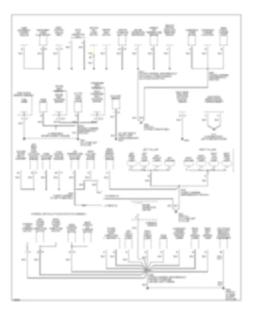
Ground Distribution Wiring Diagram (2 of 3) for Chevrolet Venture LS 2005
List of elements for Ground Distribution Wiring Diagram (2 of 3) for Chevrolet Venture LS 2005:
- (at left side of front floor console bracket) g210
- Air temperature actuator- auxiliary
- Ambient air temperature sensor
- Auxiliary module
- Blower motor relay- auxiliary
- Body control module (bcm)
- C1 e
- C313
- C314
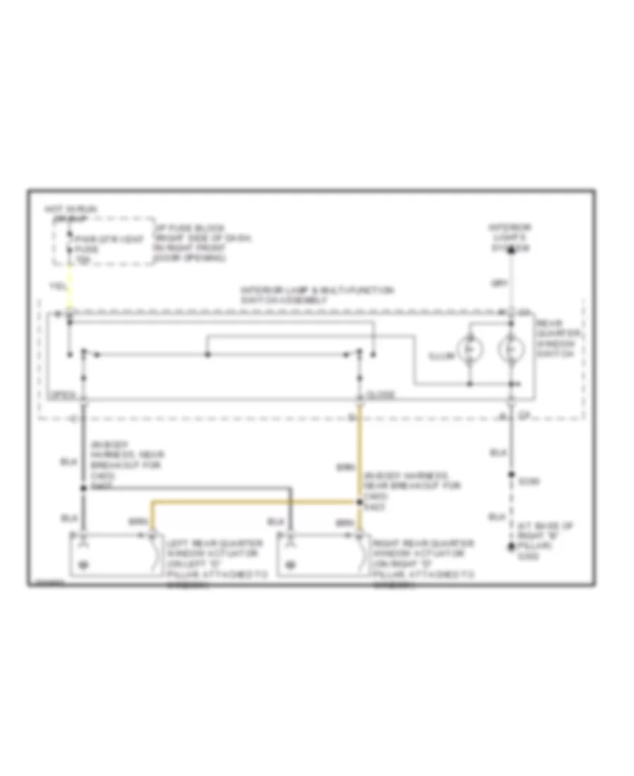
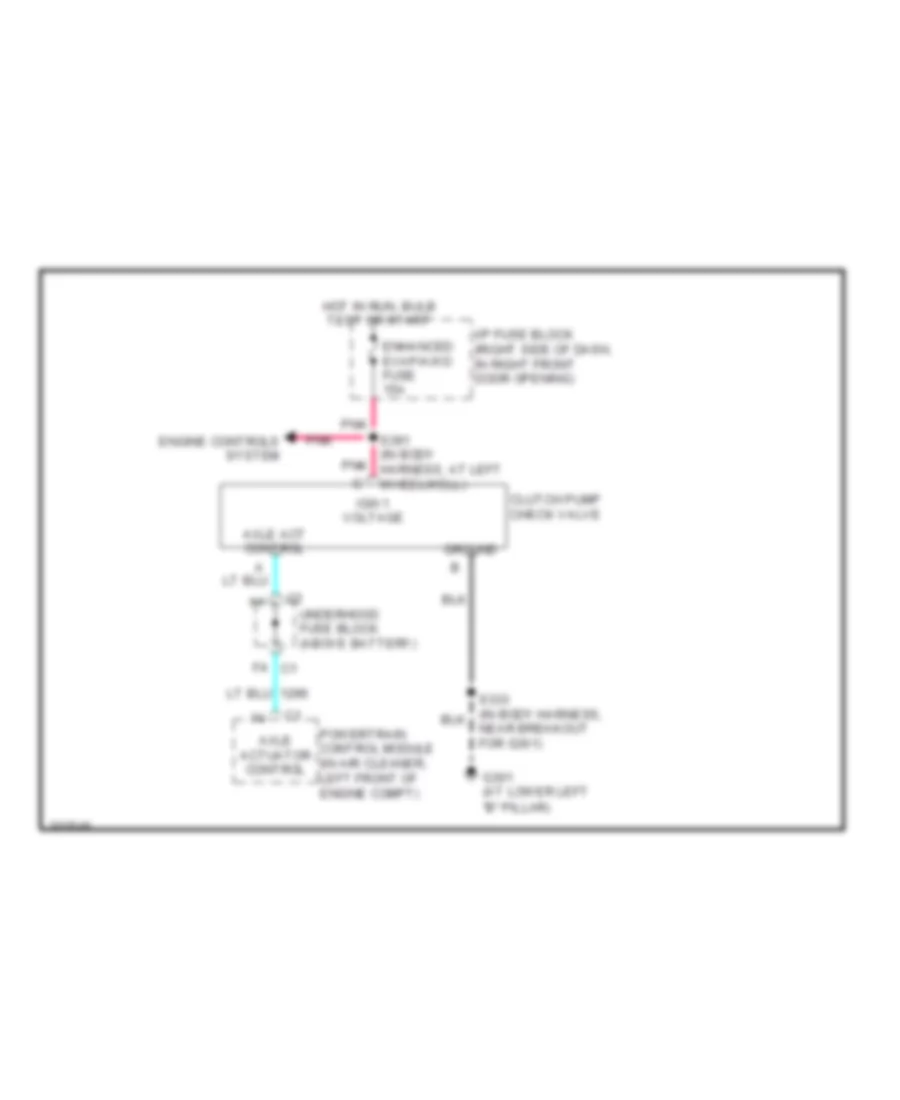
- Clutch pump check valve
- Data link connector (dlc)
- Dome lamp
- Driver information center
- Driver information center (dic)
- Driver seat adjuster switch
- Driver seat assembly
- Electronic brake control module (ebcm)
- Front passenger seat adjuster switch
- Front roof rail reading lamp
- Fuel pump
- Fuel pump & sensor assembly
- G114 (in engine compt, left & above starter)
- G200 (partial) (at right side of dash)
- G301 (at lower left "b" pillar)
- G302 (partial) (at base of right "b" pillar)
- G401 (partial) (at lower left "d" pillar)
- G402
- Hvac control module- auxiliary
- Ignition key alarm switch
- Inflatable restraint sensing & diagnostic module (sdm)
- Instrument panel cluster (ipc)
- Interior lamp & multi-function switch assembly
- Interior lamps override switch
- Left backup lamp
- Left power sliding door open/close switch
- Left rear side door actuator control module
- Left rear turn lamp
- Left tail/ stop lamp
- Left taillamp
- Left vanity mirror lamp
- Memory seat switch
- Mode actuator auxiliary
- Overhead console
- Passenger seat assembly
- Power sliding door open/close switch
- Rear auxiliary power outlet
- Rear object sensor control module
- Rear parking aid override switch
- Rear quarter window switch
- Rear roof rail reading lamp
- Rear window washer pump
- Remote control door lock receiver (rcdlr)
- Right backup lamp
- Right power sliding door open/close switch
- Right rear side door actuator control module
- Right rear turn lamp
- Right tail/ stop lamp
- Right taillamp
- Right vanity mirror lamp
- S211 (in dash harness, near breakout for window wiper/washer & multifunction switch)
- S280 (in dash harness, near breakout for p100)
- S333 (in body harness, near breakout for g301)
- S390 (in roof harness, near breakout for right sunshade lighted vanity mirror)
- S403 (in body harness, at left wheelwell)
- S406 (in body harness, near breakout for p401)
- Tan
- Theft deterrent control module
- Vehicle interface unit (viu)
- W/ rear a/c
- W/ rear seat entertainment package
- W/o rear a/c
- Windshield header courtesy/ reading lamps
- Windshield washer fluid pump
- Windshield wiper motor
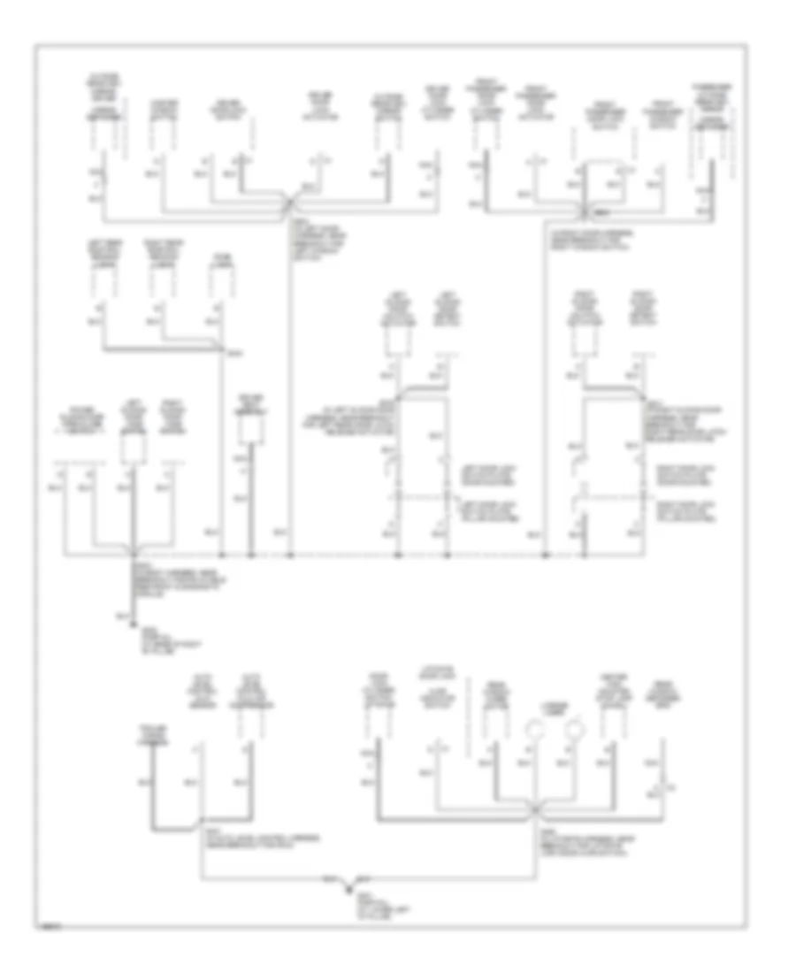
Ground Distribution Wiring Diagram (3 of 3) for Chevrolet Venture LS 2005
List of elements for Ground Distribution Wiring Diagram (3 of 3) for Chevrolet Venture LS 2005:
- (in right door harness, near breakout for right window switch)
- Ajar indicator switch
- Auto level control (alc) air compressor
- Auto level control (alc) sensor
- C1 e
- Center high mounted stop lamp (chmsl)
- Dome lamp
- Door lock cylinder switch- liftgate
- Driver door lock actuator
- Driver door lock cylinder switch
- Driver door lock switch
- Driver seat assembly
- Front passenger door lock actuator
- Front passenger door lock cylinder switch
- Front passenger door lock switch
- Front passenger window switch
- G302 (partial) (at base of right "b" pillar)
- G401 (partial) (at lower left "d" pillar)
- Left door lock switch plate (door mounted)
- Left door lock switch plate (pillar mounted)
- Left rear roof rail reading light
- Left sliding door detent switch
- Left sliding door jamb switch
- Left sliding door unlatch actuator
- License lamps
- Liftgate door lock
- Master window switch
- Mirror defogger
- Nca
- Outside rearview mirror switch
- Outside rearview mirror- driver
- Passenger outside rearview mirror
- Power sliding door open/close switch
- Rear window defogger grid
- Rear window wiper motor
- Right door lock switch plate (door mounted)
- Right door lock switch plate (pillar mounted)
- Right rear roof rail reading light
- Right sliding door detent switch
- Right sliding door jamb switch
- Right sliding door unlatch actuator
- S303 (in body harness, near breakout for inflatable restraint & diagnostic module)
- S334
- S441 (in auto level control harness, near breakout for p403)
- S460 (in liftgate harness, near breakout for liftgate lock (door ajar switch))
- S504 (in left door harness, near breakout for left window switch)
- S604
- S816 (in left sliding door harness, near breakout for left rear door latch release actuator)
- S817 (in right sliding door harness, near breakout for right rear door latch release actuator)
- Trailer wiring harness
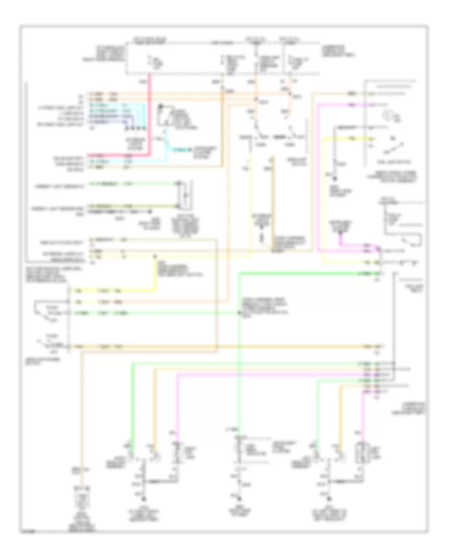
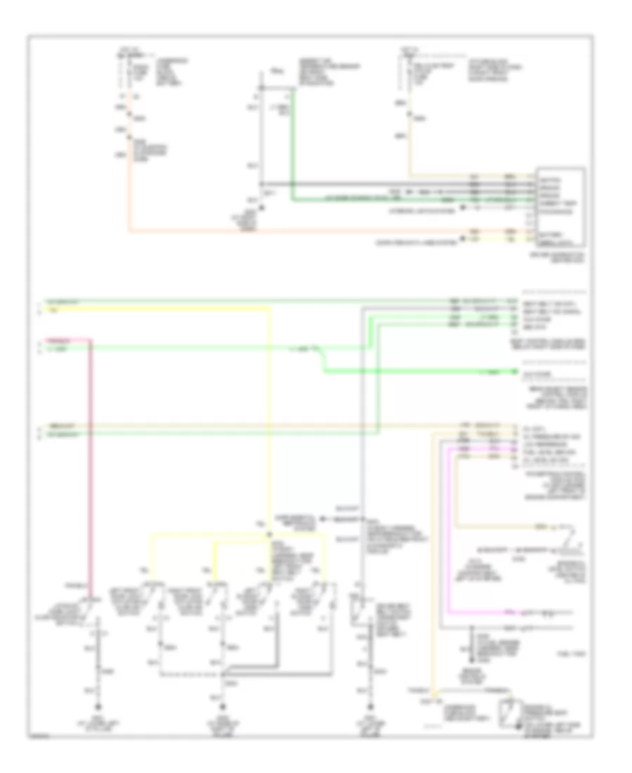
HEADLIGHTS
Headlights Wiring Diagram for Chevrolet Venture LS 2005
List of elements for Headlights Wiring Diagram for Chevrolet Venture LS 2005:
- (dash harness, near breakout for radio) s204
- (dash harness, near breakout for window wiper/washer & multifunction switch) s219
- Ambient light sensor gnd
- Ambient light sensor in
- Body control module (below right side of dash)
- C1 d
- C2 d11
- Daytime running lamp (drl) ambient light sensor (top center of i/p)
- Daytime running lamps (drl) control module (behind dash, right of steering column)
- Drl fuse 10a
- Drl/hvac/ temp/ htdst fuse 10a
- E10
- E11
- E12
- E13
- Exterior lamps out
- Exterior lights system
- Flash
- Fog lamp relay
- Fog lamp switch
- Fog lp fuse 10a
- G101 (at left front of vehicle, right of left headlight)
- G102 (at right front wheelwell, near battery)
- G200 (right side of dash)
- Gnd
- Head
- Headlamp circuit breaker 20a
- Headlamp dimmer switch
- Headlamp switch
- Headlamps on in
- High
- High beam indicator
- Hot at all times
- Hot in run
- Hot in run, bulb test or start
- I/p fuse block (right side of dash, in right front door opening)
- Ign (run)
- Ign (run/start)
- Instrument cluster system
- Instrument panel cluster
- L turn sig in
- Left fog lamp
- Left headlamp assembly
- Lf park/turn lamp out
- Low
- Off
- On ind
- Park
- Park brake in
- Park brake switch (at left kick panel)
- Park lp fuse 20a
- Pnk
- R turn sig in
- Rear window wiper/ washer & multifunction switch assembly
- Rf park/turn lamp out
- Right fog lamp
- Right headlamp assembly
- Rke activation input
- Rke lmp actv sig
- S123
- S124
- S212
- S215
- S221 (dash harness, near breakout for headlight switch)
- S230
- S264
- Tan
- Underhood fuse block (above battery)
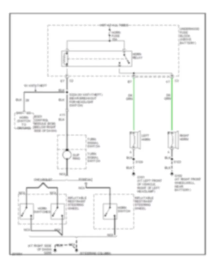
HORN
Horn Wiring Diagram for Chevrolet Venture LS 2005
List of elements for Horn Wiring Diagram for Chevrolet Venture LS 2005:
- (at right side of dash) g200
- (steering column)
- A11
- Body control module (bcm) (below right side of dash)
- Chevrolet
- D10
- G101 (at left front of vehicle, right of left headlamp)
- G102 (at right front wheelwell, near battery)
- Horn
- Horn (switch to ground)
- Horn fuse 15a
- Horn relay
- Horn switch
- Horn switches
- Hot at all times
- Inflatable restraint steering wheel
- Left
- Nca
- Pontiac
- Right horn
- S123
- S124
- S224 (w/ anti-theft) (near breakout for headlight switch)
- Slip ring
- Turn signal switch
- Underhood fuse block (above battery)
- W/ anti-theft
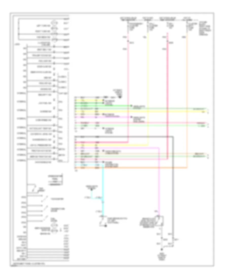
INSTRUMENT CLUSTER
Instrument Cluster Wiring Diagram (1 of 2) for Chevrolet Venture LS 2005
List of elements for Instrument Cluster Wiring Diagram (1 of 2) for Chevrolet Venture LS 2005:
- (at right side of dash) g200
- (pcm)
- A-c1
- A-c2
- Abs ind
- Accy
- Air bag ind
- Awd disable ind
- B-c1
- Battery
- Brake fluid level switch (on right side of brake fluid reservoir)
- Brake ind
- C-c1
- C-c2
- Change eng oil ind
- Charge ind
- Chime sig
- Class 2
- Cluster batt fuse 10a
- Computer data lines system
- D-c1
- D-c2
- Data line
- Door ajar ind
- E-c1
- E-c2
- Ebtcm
- Exterior lights system
- F-c1
- F-c2
- Fog lamp ind
- Fuel gauge
- G-c1
- G-c2
- G200 (at right side of dash)
- Ground
- H-c1
- H-c2
- Headlights system
- Headlights system (fog lamps)
- High beam ind
- Hot at all times
- Hot coolant temp ind
- Hot in acc or run
- Hot in run, bulb test or start
- I/p fuse block (right side of dash, in right front door opening)
- Ign
- Ign 0
- Ign 1
- Ign 1 fuse 10a
- Illumination (3 bulbs)
- Instrument panel cluster (ipc)
- Interior lights system
- Internal
- J-c2
- K-c1
- K-c2
- L-c1
- L-c2
- Left turn ind
- Logic
- Low eng oil level ind
- Low fuel ind
- Low oil pressure ind
- M-c1
- M-c2
- Mall/ cluster fuse 10a
- Odometer
- Over speed ind
- Park brake switch (at left kick panel)
- Pcm
- Pcm/passkey/ cluster fuse 10a
- Pnk
- Power distribution system (rap)
- Prndl
- Rap in
- Rear hatch ajar ind
- Right turn ind
- S209
- S210
- S211
- S230
- S242
- Seat belt ind
- Security
- Security ind
- Service engine soon ind
- Service traction ind
- Speedometer
- Tachometer
- Temperature gauge
- Thft det
- Trac off ind
- Traction active ind
- Trailer towing ind
- Trip
- Trip reset
Instrument Cluster Wiring Diagram (2 of 2) for Chevrolet Venture LS 2005
List of elements for Instrument Cluster Wiring Diagram (2 of 2) for Chevrolet Venture LS 2005:
- (in engine compartment, left of starter)
- Ambient air temperature sensor (on front right side of radiator)
- Ambient temp
- Aux chime
- Battery
- Body control module (bcm) (below right side of dash)
- Computer data lines system
- D12
- Driver information center (dic)
- Driver seat belt switch (inside right half of driver's seat belt)
- Drl/hvac/temp htd st fuse 10a
- Engine controls system
- Engine oil level switch (center of oil pan)
- Engine oil pressure (eop) switch (on lower left side of engine, above starter)
- Fuel level sen sig
- Fuel tank
- G113
- G200 (at right side of dash)
- G301 (at lower left "b" pillar)
- G302 (at base of right "b" pillar)
- G401 (at lower left "d" pillar)
- Ground
- Hot at all times
- Hot in run
- I/p fuse block (right side of dash, in right front door opening)
- Ignition
- Interior lights system
- Left front door lock actuator (ajar ind switch)
- Left sliding door jamb switch
- Liftgate door lock (ajar indicator switch)
- Low reference
- Mil cntl
- Nca
- Oil level sw sig
- Oil pressure sw sig
- Powertrain control module (pcm) (in air cleaner, left front of engine compartment)
- Pwm dimming
- Radio fuse 10a
- Rear object sensor control module (behind trim, right front of cargo area)
- Right front door lock actuator (ajar ind switch)
- Right sliding door jamb switch
- S106
- S202
- S211
- S264
- S303
- S304 (in body harness, near breakout for inflatable restraint & diagnostic module)
- S326 (w/ electric sliding side door)
- S329 (in fuel sender harness, near breakout for c305)
- S330 (in body harness, near breakout for left front seat belt switch)
- S333
- S390
- S460
- S504
- S604
- Seat belt ind cntl
- Seat belt sw signal
- Sec sys
- Serial data
- Underhood fuse block (above battery)
INTERIOR LIGHTS
Courtesy Lamps Wiring Diagram for Chevrolet Venture LS 2005
List of elements for Courtesy Lamps Wiring Diagram for Chevrolet Venture LS 2005:
- (in roof harness, near breakout for g302) s393
- A nca
- Ajar switch
- B+ input
- B+ output
- Body control module (below right side of dash)
- Cargo lamp
- Ctsy lamp fuse 10a
- Ctsy lps ctrl
- Dome
- Dome lamp
- Driver door lock actuator
- Driver dr ajar
- Front passenger door lock actuator
- Front roof rail reading lamp
- G200 (at right side of dash)
- G301 (w/ rse) (at lower left "b" pillar)
- G302 (at base of right "b" pillar)
- G302 (w/o rse) (at base of right "b" pillar)
- G401 (at lower left "d" pillar)
- Headlamp switch
- Hot at all times
- I/p fuse block (right side of dash, in right front door opening)
- If equipped
- Int lps on
- Interior lamp & multi- function switch assembly
- Interior lamps switch
- Left sliding door jamb switch
- Left vanity mirror lamp
- Liftgate door lock
- Nca
- Nca b
- Off
- Pass dr ajar
- Rear roof rail reading lamp
- Right sliding door jamb switch (front of right rear wheelwell)
- Right vanity mirror lamp
- S242
- S303
- S309 (in body harness, near breakout for c302)
- S325 (in body harness, near breakout for left sliding door jamb switch)
- S333 (w/ rse)
- S390
- S390 (w/o rse)
- S397 (in roof harness, near breakout for g302)
- S460
- S504
- S604
- Sliding dr ajar
- Tan
- W/ rse
- W/o rse
- Windshield header courtesy/ reading lamps
Instrument Illumination Wiring Diagram for Chevrolet Venture LS 2005
List of elements for Instrument Illumination Wiring Diagram for Chevrolet Venture LS 2005:
- (4 bulbs)
- (6 bulbs)
- (in body harness, near breakout for right door lock switch plate) s320
- (in dash harness, near breakout for radio) s203
- (in dash harness, near breakout for window wiper/washer & multifunction switch) s223
- (in left door harness, near breakout for left window switch)
- (in right door harness, near breakout for right window switch) s606
- (in roof harness, near breakout for power sliding door open/close switch) s395
- Audio/ video hvac control module (w/ rse & dvd player)
- Auxiliary blower motor
- Auxiliary hvac control module
- B12
- Dim ctrl
- Driver door lock switch
- Front passenger door lock switch
- Front passenger window switch
- G200 (at right side of dash)
- G201 (at left side of dash)
- G302 (at base of
- G302 (at base of right "b" pillar)
- G401 (at lower left "d" pillar)
- Gnd
- Headlamp switch
- Heated seat switch
- Hot at all times
- Hvac control module
- Hvac control module (center of dash, below radio)
- I/p fuse block (right side of dash, in right front door opening)
- Inflatable restraint steering wheel module coil
- Instrument panel cluster
- Interior lamp & multi- function switch assembly
- Interior lamps override switch
- Left power sliding door open/close switch
- Left steering wheel controls
- Master window switch
- Memory seat switch
- Multifunction switch
- Over- head console
- Park lp fuse 20a
- Power sliding door on/off switch
- Power sliding door open/ close switch
- Pwm dim
- Radio
- Rear quarter window switch
- Rear seat audio (rsa) control (if equipped)
- Rear window wiper/ washer switch
- Right "b" pillar)
- Right power sliding door open/close switch
- Right steering wheel controls
- S211
- S212
- S213
- S230
- S242
- S247
- S303
- S390
- S403
- S504
- S506
- S604
- Step dim
- Swc back- light fuse 2a
- Tcs switch
- Underhood fuse block (above battery)
MEMORY SYSTEMS
Memory Systems Wiring Diagram for Chevrolet Venture LS 2005
List of elements for Memory Systems Wiring Diagram for Chevrolet Venture LS 2005:
- (at lower left "b" pillar) g301
- (at right side of dash) g200
- (in seat harness, under driver seat)
- (not used)
- 30a
- 5v ref
- A10
- A11
- A12
- Aft
- B10
- B11
- B12
- Batt (high current)
- Class 2 serial data
- Computer data lines system
- Driver seat adjuster motor assembly
- Driver seat adjuster switch
- Driver seat assembly
- Fore
- Front down
- Front up
- Front up-dn
- Front vert down
- Front vert down ctrl
- Front vert pos sens
- Front vert up
- Front vert up ctrl
- Front vertical sensor
- Ground
- Horizontal pos sens
- Horizontal position sensor
- Horz fwd
- Horz fwd ctrl
- Horz m
- Horz rwd
- Horz rwd ctrl
- Hot at all times
- I/p fuse block (right side of dash, near door opening)
- Interior lights system
- Memory 1
- Memory 2
- Memory seat module (beneath driver seat)
- Memory seat switch
- Power
- Pwr seat circuit breaker
- Rear down
- Rear up
- Rear up-dn
- Rear vert down
- Rear vert down ctrl
- Rear vert pos sens
- Rear vert up
- Rear vert up ctrl
- Rear vertical sensor
- Recline down
- Recline fwd
- Recline fwd ctrl
- Recline pos sens
- Recline rwd
- Recline rwd ctrl
- Recline up
- S211
- S286
- S302
- S333
- S346
- S350
- S351
- S352
- Seat recline motor
- Seat recline sensor
- Sensor return
- Tan
NAVIGATION
Parking Assistant Wiring Diagram for Chevrolet Venture LS 2005
List of elements for Parking Assistant Wiring Diagram for Chevrolet Venture LS 2005:
- (in body harness, near breakout for p401)
- Amber center ind ctrl
- Amber center indicator
- Amber outside ind ctrl
- Amber outside indicator
- B/u lamp fuse 10a
- Backup lamp voltage
- Body control module (below right side of dash)
- Diagnostic input
- Engine controls system
- Exterior lights system
- G302 (at base of right "b" pillar)
- G401 (at lower left "d" pillar)
- Ground
- Hot at all times
- Hot in run or start
- I/p fuse block (right side of dash, in right front door opening)
- Ign 1 fuse 10a
- Instrument panel cluster
- Interior lamp & multi-function switch assembly
- Left rear corner object sensor
- Left rear middle object sensor
- Low ref
- Lr corner sensor sig
- Lr middle sensor sig
- Nca
- Park/neutral position switch (left rear side of engine compartment, mounted to top of transaxle)
- Pnk
- Rear object sensor control module (behind trim panel at right front of cargo area)
- Rear park chime sig
- Rear parking aid override switch
- Rear parking assist diagnostic connector (front of right rear wheelwell)
- Rear parking assist display
- Red
- Red ind ctrl
- Red indicator
- Right rear corner object sensor
- Right rear middle object sensor
- Rr corner sensor sig
- Rr middle sensor sig
- S337
- S390
- S406
- S428 (parking aid sensor harness, near right middle rear parking aid sensor)
- S429 (parking aid sensor harn, near right middle rear parking aid sensor)
- S435
- Sensor low ref
- Sensor signal
- Sensor voltage
- Sw sig in
- Telltail assy voltage
- Underhood fuse block (above battery)
- Vss signal
POWER DISTRIBUTION
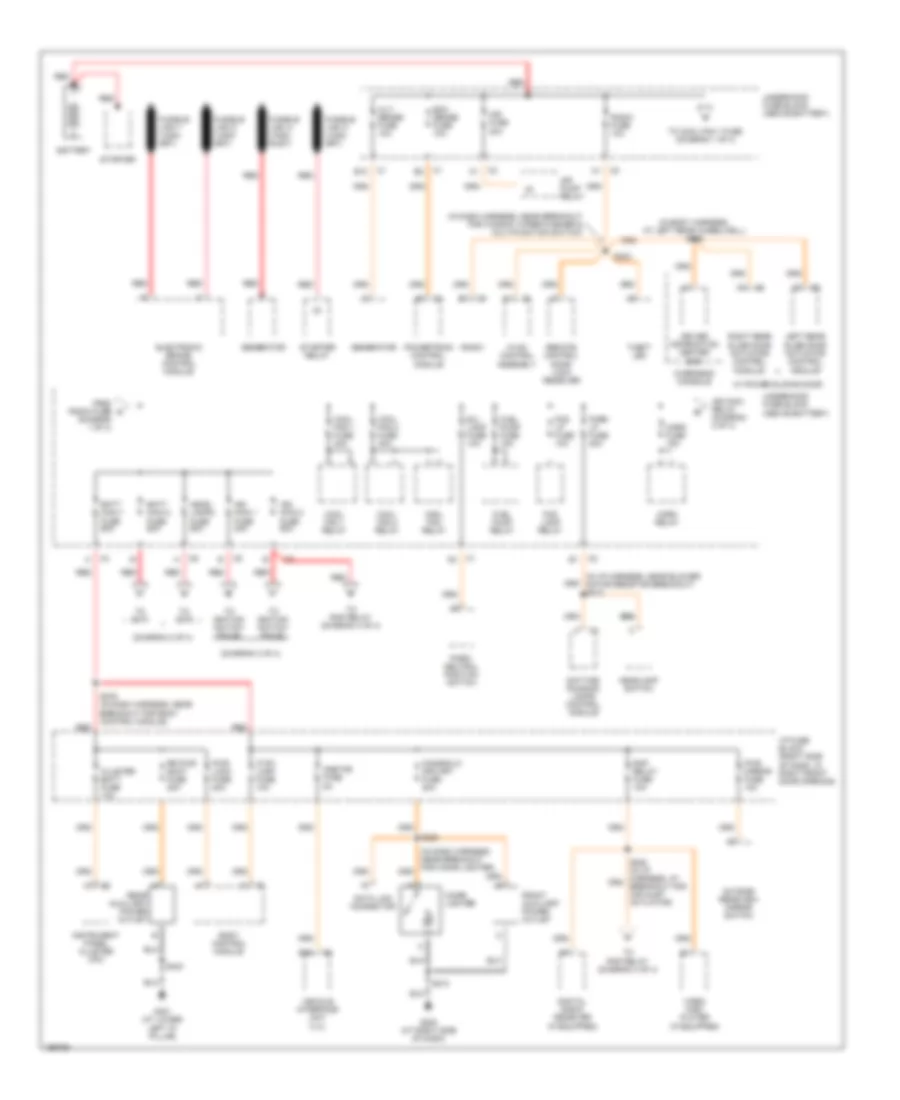
Power Distribution Wiring Diagram (1 of 4) for Chevrolet Venture LS 2005
List of elements for Power Distribution Wiring Diagram (1 of 4) for Chevrolet Venture LS 2005:
- (diagram 1 of 4)
- (diagram 2 of 4)
- (diagram 3 of 4)
- (in body harness, at left rear wheelwell) s326
- (in dash harness, near breakout for cigar lighter)
- (in dash harness, near breakout for window wiper/washer & multifunction switch)
- (in i/p harness, near blower motor resistor breakout) s212
- Air fuse 30a
- Air pump relay
- Alt/ sense fuse 10a
- B/u lamp fuse 10a
- Batt main 1 fuse 60a
- Batt main 2 fuse 60a
- Battery
- Body control module
- Cigar lighter
- Cigar/dlc/ apo frt fuse 20a
- Cluster batt fuse 10a
- Cool fan 1 fuse 30a
- Cool fan 1 relay
- Cool fan 2 fuse 30a
- Cool fan 2 relay
- Cool fan relay
- Ctsy lamp fuse 10a
- Data link connector
- Daytime running lamps control module
- Digital radio receiver (if equipped)
- Driver information center (dic)
- E12
- E16
- Ecm sense fuse 10a
- Electronic brake control module
- Fog lamp relay
- Fog lp fuse 10a
- From radio fuse a
- Front auxiliary power outlet
- Fuel pump fuse 15a
- Fuel pump relay
- Fusible link a (10ga- rust)
- G200 (at right side of dash)
- G401 (at lower left "d" pillar)
- Generator
- Head- lamps fuse 60a
- Headlamp switch
- Horn fuse 15a
- Horn relay
- Hvac control assembly
- I/p fuse block (right side of dash, in right front door opening)
- Ign main 1 fuse 40a
- Ign main 2 fuse 60a
- Ign main relay (diagram 2 of 4)
- Instrument panel cluster (ipc)
- Left rear slide door actuator control module
- Onstar fuse 5a
- Outside rearview mirror switch
- Overhead console
- Park lp fuse 20a
- Park/ neutral position switch
- Powertrain control module
- Pwr lock fuse 20a
- Pwr mirror fuse 10a
- Radio
- Radio fuse 10a
- Rap relay fuse 10a
- Rear auxiliary power outlet
- Red
- Remote control door lock receiver
- Right rear slide door actuator control module
- Rr pwr sckt fuse 20a
- S202
- S213
- S238
- S276 (in dash harness, near breakout for body control module)
- S403
- Starter
- Starter relay
- Theft led
- To cool fan 1 fuse (diagram 1 of 4)
- To ignition switch pin d2
- To ignition switch pin d5
- To rap relay (diagram 4 of 4)
- To s274
- To s278
- Underhood fuse block (above battery)
- Vehicle interface unit (viu)
- Video disc player (if equipped)
- W/ power sliding door
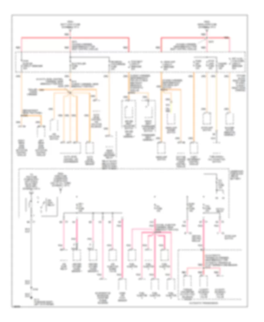
Power Distribution Wiring Diagram (2 of 4) for Chevrolet Venture LS 2005
List of elements for Power Distribution Wiring Diagram (2 of 4) for Chevrolet Venture LS 2005:
- (behind right rear trim panel) s322
- (diagram 1 of 4)
- (in auto level control harness, near breakout for p403) s445
- (in automatic transaxle harness, near breakout for automatic transaxle fluid temperature sensor) s115
- (in dash harness, near breakout for body control module)
- (in fuel injector pnk
- 1-2 shift solenoid (1-2 ss) valve
- 2-3 shift solenoid (2-3 ss) valve
- A/c clu fuse 10a
- A/c clu relay
- A12
- Air inflator switch
- Air injection bleed valve
- Air pump relay
- Auto level control air compressor
- Auto level control air inflator solenoid
- Auto level control sensor
- Automatic transmission
- Blower motor resistor assembly
- Daytime running lamps control module
- Driver seat adjuster switch
- Driver seat assembly
- E10
- Elc/trailer fuse 25a
- Elek ign fuse 15a
- Evaporative emissions canister purge solenoid
- From batt main 2 fuse
- From headlamps fuse
- From horn fuse (underhood fuse block) (hot at all times) (diagram 1 of 4)
- Front seat passenger adjuster switch
- Frt hvac hi blower circuit breaker 30a
- Fuel injector
- G113 (in engine compt, left of starter)
- Harness, near breakout for c102) s109
- Hazard fuse 15a
- Headlamp circuit breaker 20a
- Headlamp dimmer switch
- Headlamp switch
- Heated oxygen (ho2s) sensor 1
- Heated oxygen (ho2s) sensor 2
- I/p fuse block (right side of dash, in right front door opening)
- Ign 1 u/h fuse 15a
- Ign main relay
- Ignition control module
- Inj fuse 10a
- Left rear side door actuator control module
- Mass air flow sensor
- Nca
- Near breakout for inflatable restraint sensing & diagnostic module) s302
- Pass key fuse 10a
- Passenger seat assembly
- Pnk
- Pwr seat circuit breaker 30a
- Pwr sldg dr circuit breaker 30a
- Rear window defogger relay
- Red
- Relay block (below right side of dash, next to bcm)
- Right rear side door actuator control module
- Rr defog/ htd mirrors fuse 30a
- S106
- S274 (in dash harness, near breakout for body control module)
- S278
- S412 (in body harness, near breakout for p401)
- Stop lamp fuse 15a
- Stoplamp switch
- Tcc fuse 10a
- Theft deterrent control module
- To pcm fuse (fuse block) (hot in run, bulb test or start) (diagram 3 of 4)
- Torque converter clutch (tcc) solenoid valve
- Trailer wiring harness
- Turn signal/ multifunction switch
- Underhood fuse block (above battery)
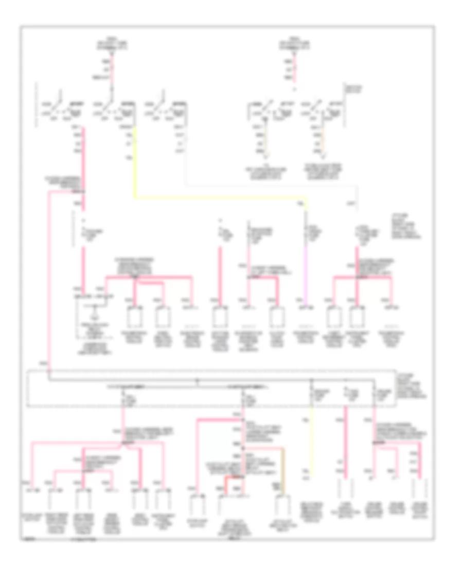
Power Distribution Wiring Diagram (3 of 4) for Chevrolet Venture LS 2005
List of elements for Power Distribution Wiring Diagram (3 of 4) for Chevrolet Venture LS 2005:
- (if equipped)
- (in body harness, at left wheelwell) s391
- (in body harness, near breakout for p401) s337
- (in dash harness, near pnk breakout for security indicator light) s209
- (in dash harness, near breakout for radio) s228
- (in dash harness, near breakout for window wiper/washer & multifunction switch) s266
- (in dash harness, near breakout pnk
- (in engine harness, near breakout for powertrain control module) s108
- A10
- A11
- A13
- Acc
- Acc 1
- Below sit-n-lift seat)
- Body control module
- Bulb test
- C10
- C13
- Clutch pump check valve
- Crank
- Cruise control module
- Cruise control on/off switch
- Cruise control release switch
- Cruise fuse 10a
- D11
- Daytime running lamps control module
- Drl fuse 10a
- Electronic brake control module
- Enhanced evap/awd fuse 15a
- Evaporative emission canister vent solenoid
- For security indicator light) s210
- From ign main 1 fuse (diagram 1 of 4)
- From ign main 2 fuse (diagram 1 of 4)
- From ign main relay (diagram 2 of 4)
- I/p fuse block (right side of dash, in right front door opening)
- Ign 0
- Ign 1
- Ign 1 fuse 10a
- Ign 3
- Ignition switch
- Inflatable restraint sensing & diagnostic module
- Instrument panel cluster (ipc)
- Left rear side door actuator control module
- Lock
- Off
- Park/ neutral position switch
- Pcm/ crank fuse 10a
- Pcm/ pass key/ cluster fuse 10a
- Pcm/abs fuse 10a
- Pnk
- Powertrain control module
- Powertrain control module (pcm)
- Rear object sensor control module
- Red
- Right rear side door actuator control module
- Run
- S361 (in sit-n-lift seat harness, (in sit-n-lift seat harness, below sit-n-lift seat) s362
- S372 (in sit-n-lift seat jumper harness, near right sliding door)
- Sdm/sir fuse 15a
- Sit-n-lift seat/brake transmission shift interlock relay
- Sit-n-lift seat/ignition relay
- Start
- Stoplamp switch
- T/sig fuse 10a
- Theft deterrent control module
- To drl/hvac/temp/ heated seat fuse (i/p fuse block) (diagram 4 of 4)
- To frt wpr/wshr fuse (i/p fuse block) (diagram 4 of 4)
- Turn signal/ multifunction switch
- Underhood fuse block (above battery)
- W/ sit-n-lift seat
- W/o sit-n-lift seat
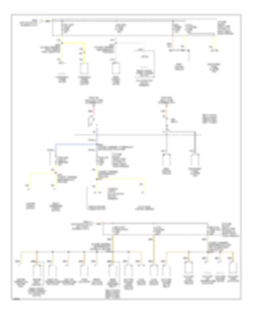
Power Distribution Wiring Diagram (4 of 4) for Chevrolet Venture LS 2005
List of elements for Power Distribution Wiring Diagram (4 of 4) for Chevrolet Venture LS 2005:
- (diagram 3 of 4)
- (in body harness, near breakout for c302) s317
- (in body harness, near breakout for left sliding door jamb switch) s345
- (in dash harness, near breakout for relay center) s264
- Auto level control sensor
- Auxiliary air temperature actuator
- Auxiliary blower motor
- Auxiliary blower motor relay
- Auxiliary hvac control module
- Auxiliary mode actuator
- Bcm prgrm fuse 10a
- Body control module
- Daytime running lamps control module
- Driver information center (dic)
- Drl/hvac/ temp/htd st fuse 10a
- From ign main 2 maxi fuse (diagram 1 of 4)
- From ignition switch
- From ignition switch j (hot in run) (diagram 3 of 4)
- From rap relay fuse (diagram 1 of 4)
- Front passenger window switch
- Frt wpr/ wshr fuse 25a
- Heated seat switch
- Hvac blower fuse 25a
- Hvac control module
- I/p fuse block (right side of dash, in right front door opening)
- Instrument panel cluster (ipc)
- Interior lamp & multifunction switch assembly
- Left air temperature actuator
- Mall/ cluster fuse 10a
- Master window switch
- Mode actuator
- Multifunction switch assembly
- Pwr otr vent fuse 10a
- Pwr wdo circuit breaker 30a
- Rap relay
- Rear quarter window switch
- Rear window defogger relay
- Rear window wiper motor
- Rear window wiper/ washer switch
- Rear window wiper/washer & multifunction switch
- Recir- culation actuator
- Red
- Relay block (below right side of dash, next to bcm)
- Right air temperature actuator
- Rr hvac/ temp cont fuse 25a
- Rr wpr/ wshr fuse 20a
- S245 (in dash harness, near breakout for radio)
- S249 (in dash harness, right side of dash, near p100)
- S307 (in body harness, near breakout for c302)
- Windshield wiper motor
- Windshield wiper/ washer switch
POWER DOOR LOCKS
Power Door Locks Wiring Diagram for Chevrolet Venture LS 2005
List of elements for Power Door Locks Wiring Diagram for Chevrolet Venture LS 2005:
- (above battery) underhood fuse block
- (at base of right "b" pillar)
- (at base of right "b" pillar) g302
- (at lower left "d" pillar)
- (behind center top of i/p) remote control door lock receiver (rcdlr)
- (body harness near breakout for inflatable restraint & diagnostic module)
- (in body harness, near breakout for c302) s319
- (in body harness, near breakout for left front seat belt switch)
- (in body harness, near breakout for left front seat belt switch) s327
- (in sit-n-lift seat jumper harness, near right sliding door)
- (w/ rke)
- Accessory
- All door lk
- All door unlk
- B/u lamp fuse 10a
- Batt (courtesy)
- Batt (door lks)
- Body control module (below right side of dash)
- C1 c6
- C11
- C13
- C200
- Ctsy lamp fuse 10a
- Door ajar ind
- Door lock in
- Door unlock in
- Driver door lock actuator
- Driver door lock cylinder switch
- Driver door lock switch
- Drivr door unlk
- Front passenger door lock actuator
- Front passenger door lock cylinder switch
- Front passenger door lock switch
- G200 (at right side of dash)
- G302
- G302 (at base of right "b" pillar)
- G401
- Ground
- Harness, near breakout for left front seat belt switch)
- Hot at all times
- Hot in accy or run
- Hot in run, bulb test or start
- I/p fuse block (right side of dash, in right front door opening)
- Ign 1 fuse 10a
- Ignition 1
- Instrument cluster
- Interior lights system
- Key sw lock
- Key sw unlk
- Keyless entry
- Left door lock switch plate
- Left rear door lock actuator
- Left sliding door jamb switch
- Liftgate door lock actuator
- Liftgate door lock cylinder switch
- Lock
- Mall/ cluster fuse 10a
- Nca
- Park in
- Park/neutral position switch (left rear side of engine compt, mounted to top of transaxle)
- Pnk
- Power
- Pwr lock fuse 20a
- Radio fuse 10a
- Right door lock switch plate
- Right rear door lock actuator
- Right sliding door jamb switch (front of right rear wheelwell)
- S202
- S209
- S211
- S303
- S311 (body harn, under right front door sill, approximately 13 cm (5 in) from breakout for c302)
- S314
- S315
- S323 (in body
- S330
- S370
- S460
- S504
- S604
- Seats system (w/ sit-n- lift seat)
- Sliding door
- Tan
- Trunk, tailgate, fuel doors system
- Underhood fuse block (above battery)
- Unlock
- Vehicle communication interface module (below left side of dash)
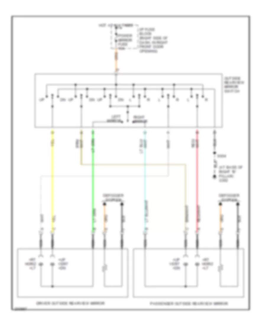
POWER MIRRORS
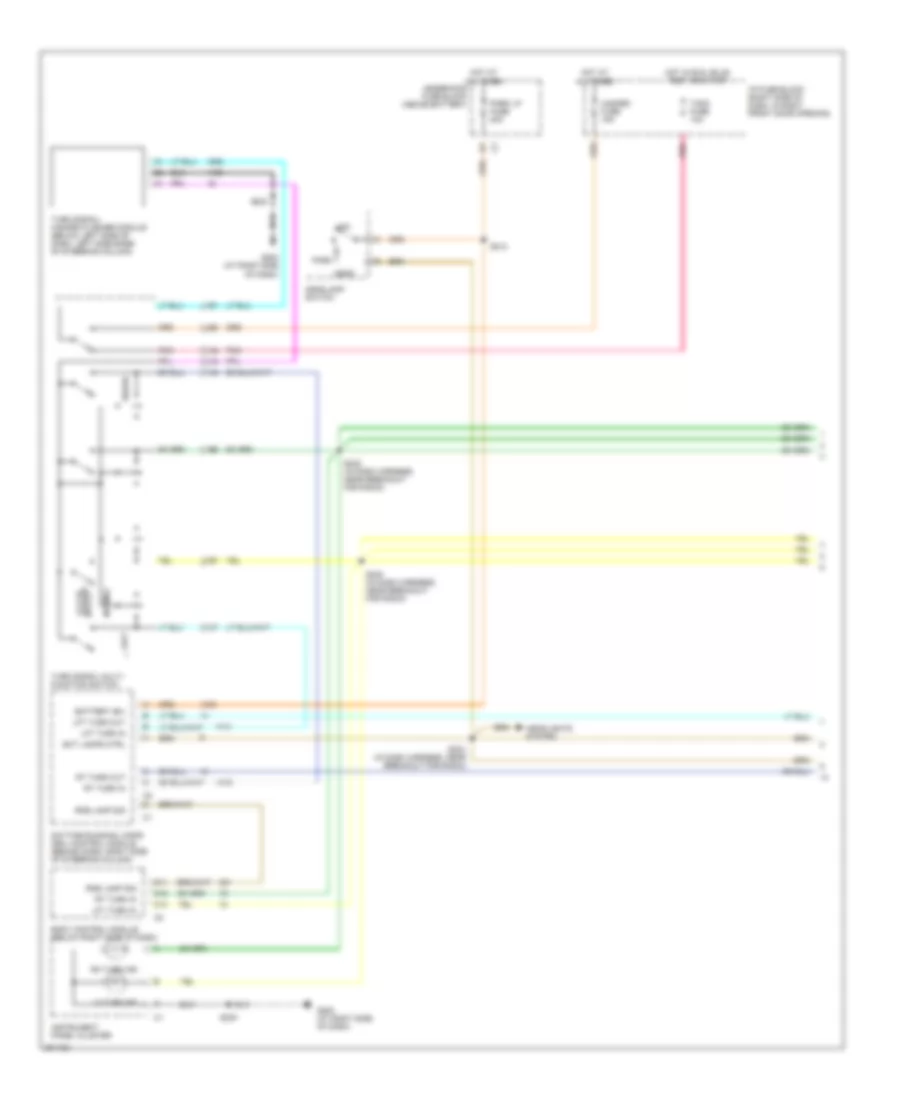
Power Mirrors Wiring Diagram for Chevrolet Venture LS 2005
List of elements for Power Mirrors Wiring Diagram for Chevrolet Venture LS 2005:
- (at base of right "b" pillar) g302
- +rt horiz +lt
- +up vert +dn
- Defogger system
- Driver outside rearview mirror
- Hot at all times
- I/p fuse block (right side of dash, in right front door opening)
- Left mirror
- Nca
- Outside rearview mirror switch
- Passenger outside rearview mirror
- Power mirror fuse 10a
- Right mirror
- S504
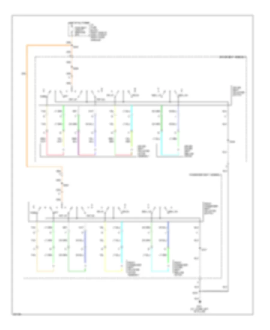
POWER SEATS
8-Way Adjustable Power Seat Wiring Diagram for Chevrolet Venture LS 2005
List of elements for 8-Way Adjustable Power Seat Wiring Diagram for Chevrolet Venture LS 2005:
- Aft
- Driver power seat recline motor
- Driver seat adjuster motor assembly
- Driver seat adjuster switch
- Driver seat assembly
- Fore
- Front passenger power seat recline motor
- Front passenger seat adjuster motor assembly
- Front passenger seat adjuster switch
- Frt dn
- Frt up
- G301 (at lower left "b" pillar)
- Hot at all times
- I/p fuse block (right side of dash, in right front door opening)
- Passenger seat assembly
- Pwr seat circuit breaker 30a
- Recl dn
- Recl up
- Rr dn
- Rr up
- S285
- S286
- S302
- S333
- S346
- S347
- Tan
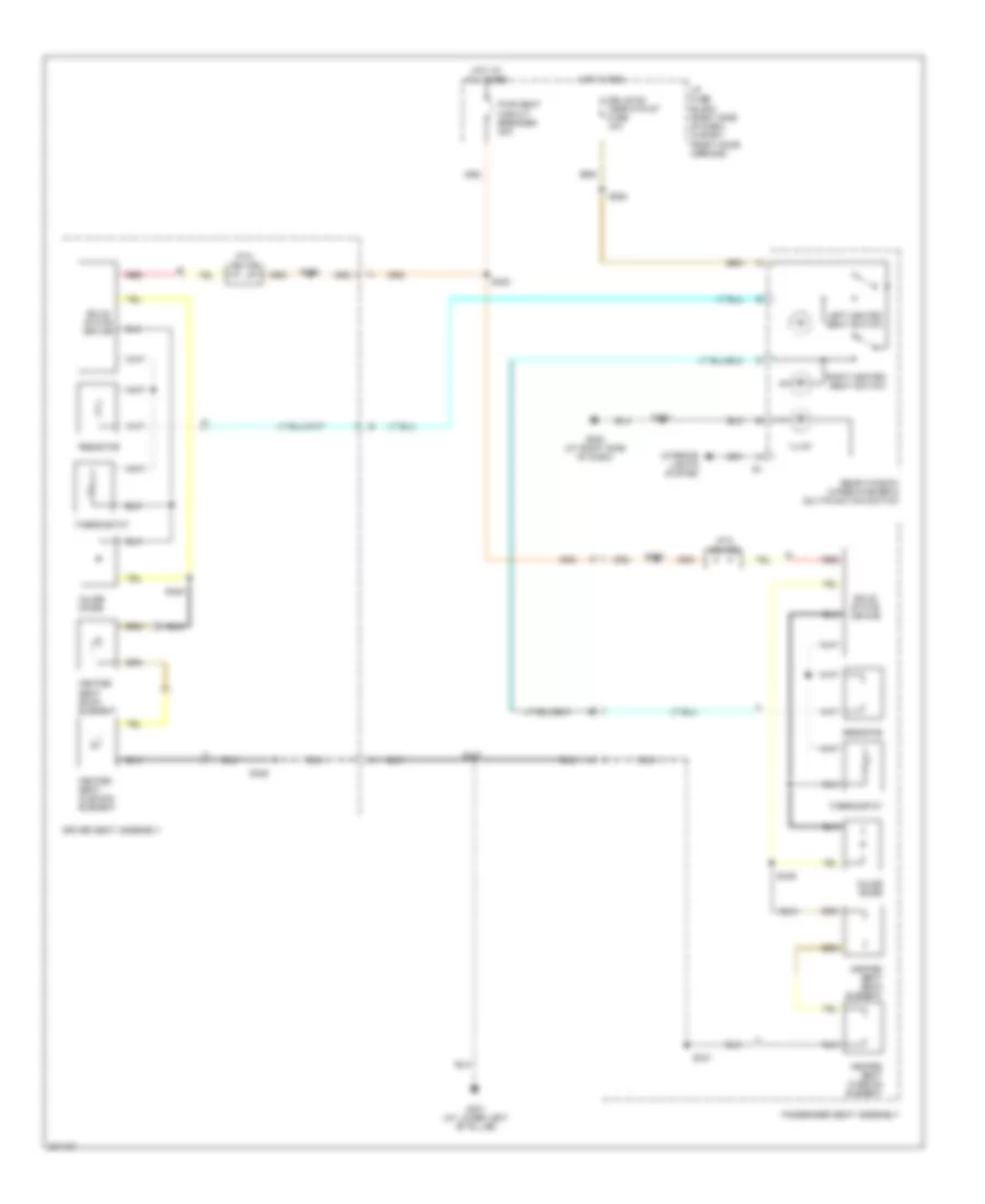
Heated Seats Wiring Diagram for Chevrolet Venture LS 2005
List of elements for Heated Seats Wiring Diagram for Chevrolet Venture LS 2005:
- Driver seat assembly
- Drl/hvac temp/htd st fuse 10a
- G200 (at right side of dash)
- G301 (at lower left "b" pillar)
- Heated seat back element
- Heated seat cushion element
- Hot at all times
- Hot in run
- I/p fuse block (right side of dash, in right front door opening)
- Illum
- Inline diode
- Interior lights system
- Left heated seat switch
- Passenger seat assembly
- Ptc device
- Pwr seat circuit breaker 30a
- Rear window wiper/washer & multifunction switch
- Red
- Resistor
- Right heated seat switch
- S230
- S264
- S285
- S286
- S302
- S333
- S346
- S347
- S348
- S349
- Solid state device
- Thermostat
Sit-N-Lift Seat Wiring Diagram (1 of 2) for Chevrolet Venture LS 2005
List of elements for Sit-N-Lift Seat Wiring Diagram (1 of 2) for Chevrolet Venture LS 2005:
- (below sit- n-lift seat)
- (below sit-n-lift seat)
- Aj08
- Aj10
- Aje1
- Aje2
- As01
- As04
- As05
- As06
- As07
- As14
- As16
- As17
- As19
- As20
- As21
- As29
- As30
- As31
- As36
- B/u lamp fuse 10a
- Battery
- Circuit breaker 8a
- Encoder
- Fuse 25a
- G301 (at lower left "b" pillar)
- G303
- Ground
- Hot at all times
- I/p fuse block (right side of dash, in right front door opening)
- Ign sw
- Lift lower limit switch
- Lift lwr limit sw sig
- Lift mtr ctrl
- Lift upper limit switch
- Lift uppr limit sw sig
- Nca
- Park sw sig
- Park/ neutral position switch (left rear side of engine compartment, mounted to top of transaxle)
- Power seats circuit breaker 30a
- Red
- Remote dwn sw sig
- Remote up sw sig
- Rr sldng dr jmb sw sig
- S302
- S366
- S367
- S368
- Shift intrlck rly ctrl
- Sit-n- lift fuse 3a
- Sit-n-lift seat circuit breaker (below sit-n-lift seat)
- Sit-n-lift seat module (below sit- n-lift seat)
- Splice pack sp1 (below sit-n-lift seat)
- Splice pack sp2 (below sit-n-lift seat)
- Swivel in limit sw sig
- Swivel inside limit switch (below sit-n-lift seat)
- Swivel motor
- Swivel mtr ctrl
- Swivel out limit sw sig
- Swivel outside limit switch
- Swvl mtr hall sen sig
- Swvl mtr hall sen vlt
- Underhood fuse block (above battery)
- V02
Sit-N-Lift Seat Wiring Diagram (2 of 2) for Chevrolet Venture LS 2005
List of elements for Sit-N-Lift Seat Wiring Diagram (2 of 2) for Chevrolet Venture LS 2005:
- (below sit-n-lift seat)
- (below sit-n-lift seat) sit-n-lift seat/ brake transmission shift interlock relay
- (below sit-n-lift seat) sit-n-lift seat/ ignition relay
- (below sit-n-lift seat) sit-n-lift seat/door jamb switch relay
- (in sit-n-lift seat harness, below sit-n-lift seat)
- (in sit-n-lift seat harness, below sit-n-lift seat) s363
- (in sit-n-lift seat jumper harness, near right sliding door) s370
- Below sit-n-lift seat)
- Body control module (below right side of dash)
- Door ajar ind
- G303
- Gnd
- Hot in run/start/ bulb test
- I/p fuse block (right side of dash, in right front door opening)
- Ign
- Ign 1 fuse 10a
- Instrument cluster system
- Instrument panel cluster
- Interior lights system
- Nca
- Pnk
- Pnp switch sig
- Red
- Right sliding door jamb switch (closed w/ door open) (front of right rear wheelwell)
- S325 (in body harness, near breakout for left sliding door jamb switch)
- S330 (in body harness, near breakout for left front seat belt switch)
- S360
- S361
- S362
- S371 (in sit-n-lift seat jumper harness, near right sliding door)
- S372
- Shift interlock system
- Sit-n-lift seat lift motor
- Sit-n-lift seat remote
- Sliding door switch sig
- Splice pack sp1 (below sit-n-lift seat)
- Splice pack sp2 (below sit-n-lift seat)
- Stop- lamp switch (mounted on top of brake pedal support)
POWER TOP/SUNROOF
Power Top/Sunroof Wiring Diagram for Chevrolet Venture LS 2005
List of elements for Power Top/Sunroof Wiring Diagram for Chevrolet Venture LS 2005:
- A10
- Close
- G303
- Hot in run or acc
- I/p fuse block
- Nca
- Off
- Open
- Red
- Sun roof fuse 23 20a
- Sun roof motor
- Sun roof switch
POWER WINDOWS
Power Windows Wiring Diagram for Chevrolet Venture LS 2005
List of elements for Power Windows Wiring Diagram for Chevrolet Venture LS 2005:
- (at base of right "b" pillar) g302
- Down
- Driver
- Driver window motor
- Express
- Express down module
- Front passenger window motor
- Front passenger window switch
- Hot in run or rap
- I/p fuse block (right side of dash, in right front door opening)
- Illum
- Interior lights system
- Master window switch
- Passenger
- Pwr wdo circuit breaker 30a
- S303
- S307
- S504
- S604
- Tan
Rear Quarter Windows Wiring Diagram for Chevrolet Venture LS 2005
List of elements for Rear Quarter Windows Wiring Diagram for Chevrolet Venture LS 2005:
- (at base of right "b" pillar) g302
- (in body harness, near breakout for c403) s423
- (in body harness, near breakout for c403) s427
- Close
- Hot in run or rap
- I/p fuse block (right side of dash, in right front door opening)
- Illum
- Interior lamp & multi-function switch assembly
- Interior lights system
- Left rear quarter window actuator (on left "d" pillar, attached to window)
- Open
- Pwr qtr vent fuse 10a
- Rear quarter window switch
- Right rear quarter window actuator (on right "d" pillar, attached to window)
- S390
RADIO
Base Radio Wiring Diagram for Chevrolet Venture LS 2005
List of elements for Base Radio Wiring Diagram for Chevrolet Venture LS 2005:
- A10
- A11
- A12
- Am/fm
- B10
- B11
- B12
- Battery
- Class 2
- Coax
- Computer data lines system
- D6 (not used)
- Dim sig
- E8 (not used)
- G201 (at left side of dash)
- Ground
- Hot at all times
- Inflatable restraint steering wheel module coil
- Interior lights system
- Left front door speaker
- Left rear liftgate speaker
- Left steering wheel controls
- Lf +
- Lf -
- Lr +
- Lr -
- Mute
- Play
- Pnk
- Preset
- Radio
- Radio front glass antenna
- Radio fuse 10a
- Rear audio
- Red
- Ref pwr
- Rf +
- Rf -
- Right front door speaker
- Right rear liftgate speaker
- Right steering wheel controls
- Rr +
- Rr -
- S202
- S247
- Seek dn
- Seek up
- Step dim
- Tan
- Underhood junction block (above battery)
- Vol dn
- Vol up
- Whl ctrls
Premium Sound Radio Wiring Diagram for Chevrolet Venture LS 2005
List of elements for Premium Sound Radio Wiring Diagram for Chevrolet Venture LS 2005:
- (in dash harness, behind center of dash) s225
- 2 ser data
- A10
- A11
- A12
- Am/fm
- Antenna
- Audio (-)
- Audio common
- Audio ctrl in
- Audio out -
- B10
- B11
- B12
- Bare
- Battery
- Class 2
- Class 2 data
- Coax
- Computer data lines system
- Digital radio antenna
- Digital radio receiver
- Dim sig
- Drain wire
- G201 (at left side of dash)
- Ground
- Hot at all times
- I/p fuse block (right side of dash, in right front door opening)
- Inflatable restraint steering wheel module coil
- Interior lights system
- L audio sig
- Lamp voltage
- Left audio sig
- Left front door speakers
- Left rear liftgate speaker
- Left steering wheel controls
- Lf +
- Lf -
- Lr +
- Lr -
- Lr speaker out (+)
- Lr speaker out (-)
- Mute
- Nca
- Play
- Pnk
- Preset
- R audio sig
- Radio
- Radio front glass antenna
- Radio fuse 10a
- Radio on sig
- Rap relay fuse 10a
- Rear audio
- Rear seat audio control
- Red
- Ref pwr
- Remote control sig
- Rf +
- Rf -
- Right audio sig
- Right front door speakers
- Right rear liftgate speaker
- Right steering wheel controls
- Rr +
- Rr -
- Rr speaker out (+)
- Rr speaker out (-)
- S202
- S220
- S247
- Satellite
- Seek dn
- Seek up
- Step dim
- Step dim sig
- Tan
- Terrestrial
- Underhood fuse block (above battery)
- Vehicle communication interface module (below left side of dash)
- Vol dn
- Vol up
- Whl ctrls
Video System Wiring Diagram for Chevrolet Venture LS 2005
List of elements for Video System Wiring Diagram for Chevrolet Venture LS 2005:
- (not used)
- A10
- A11
- A12
- Air conditioning system
- Aud out -
- Audio out -
- B10
- B11
- B12
- Bare
- Control sig
- Dimming sig
- Door pos sig
- Drain wire
- Dvd audio sig
- Dvd data sig
- Dvd l sig +
- Dvd lf sig +
- Dvd r sig +
- Dvd rt sig +
- Dvd sig -
- Enable switch
- G201 (at left side of dash)
- Ground
- Hi spd relay
- Hot at all times
- Hvac ground
- Hvac volt
- I/p fuse block (right side of dash, right front door opening)
- Interior lights system
- L aud sig
- Left aud sig
- Left rear liftgate speaker
- Low spd ntrl
- Lr spk out +
- Lr spk out -
- M spd cntrl
- R audio sig
- Radio
- Rap relay fuse 10a
- Rear audio/ video hvac control module (part of overhead console)
- Rear seat sig
- Red
- Right aud sig
- Right rear liftgate speaker
- Rr spk out +
- Rr spk out -
- Rr spk out-
- S220
- S247
- Serial data
- Step dim sig
- Tan
- Temp control
- Vehicle interface communication module (below left side of dash)
- Video disc player
- Video sig +
- Video sig -
SHIFT INTERLOCK
Shift Interlock Wiring Diagram for Chevrolet Venture LS 2005
List of elements for Shift Interlock Wiring Diagram for Chevrolet Venture LS 2005:
- (in sit-n-lift seat jumper harness, near right sliding door)
- (w/o mobility seat) (w/ mobility seat)
- A/t shift lock control solenoid (inside steering column, near ignition switch)
- G113 (in engine compt, left of starter)
- Hot in run, bulb test or start
- I/p fuse block (right side of dash, in right front door opening)
- Ign 1 fuse 10a
- Park/neutral position switch (left rear side of engine compt, mounted to top of transaxle)
- Pnk
- S106
- S209 s372
- Seats system
- Stoplamp switch (mounted to brake pedal support)
- Tcc switch
- W/ sit-n- lift seat
- W/o sit-n- lift seat
STARTING/CHARGING
Charging Wiring Diagram for Chevrolet Venture LS 2005
List of elements for Charging Wiring Diagram for Chevrolet Venture LS 2005:
- (at right front wheelwell, near battery) g100
- (in engine compt, left of starter) g113
- (not used)
- Alt/sense fuse 10a
- Batt
- Battery
- Battery indicator
- Class 2 serial data
- Class 2 serial data line
- Computer data lines
- E12
- Fusible link a (10 ga- rust)
- Generator
- Generator terminal l output
- Hot at all times
- Hot in run, bulb test or start
- I/p fuse block (right side of dash, in right front door opening)
- Ign 1 fuse 10a
- Ign 1 voltage
- Instrument panel cluster
- Logic
- Pnk
- Power distribution system
- Powertrain control module (pcm) (secured in air cleaner assembly, left front of engine compartment)
- Red
- S209
- Splice pack sp205
- Starter
- Underhood fuse block (above battery)
Starting Wiring Diagram for Chevrolet Venture LS 2005
List of elements for Starting Wiring Diagram for Chevrolet Venture LS 2005:
- (at right right front wheelwell, near battery) g100
- (in engine compt, left of starter) g113
- (in engine harness, near breakout for pcm) s108
- Acc
- Batt
- Battery
- Bulb test
- C10
- Class 2 serial data line
- Crank
- Crank relay control
- D11
- Data link connector (below steering column, on knee bolster)
- Fusible link a (10-ga rust)
- Generator
- Hold- in coil
- Hot at all times
- Hot in run, bulb test & start
- I/p fuse block (right side of dash, in right front door opening)
- Ign main 1 40a
- Ignition crank sense
- Ignition switch
- Lock
- Off
- Pcm/ crank fuse 10a
- Pcm/abs fuse 10a
- Pnk
- Power distribution system
- Powertrain control module (pcm) (secured in air cleaner assembly, left front of engine compartment)
- Pull- in coil
- Red
- Run
- Splice pack sp205
- Start
- Starter motor
- Starter relay
- Starter solenoid
- Underhood fuse block (above battery)
SUPPLEMENTAL RESTRAINTS
Supplemental Restraints Wiring Diagram for Chevrolet Venture LS 2005
List of elements for Supplemental Restraints Wiring Diagram for Chevrolet Venture LS 2005:
- (at base of right "b" pillar) g302
- (right top of dash, above glove box) inflatable restraint ip module
- A10
- A11
- A12
- A13
- A14
- A15
- A16
- A17
- A18
- Air bag ind
- Body control module (bcm) (below right side of dash)
- Case ground
- Data link connector (dlc) (partial) (below steering column, on knee bolster)
- Driver seat assembly
- Driver seat belt input
- Driver seat belt switch (open with driver seat belt buckled)
- G302 (w/ value van) (at base of right "b" pillar)
- Ground
- High control
- Hot in run, bulb test & start
- I/p fuse block (right side of dash, in right front door opening)
- Ign
- Ignition
- Inflatable restraint sensing & diagnostic module (sdm) (below right front seat)
- Inflatable restraint steering wheel module (center of steering wheel)
- Inflatable restraint steering wheel module coil
- Instrument panel cluster (ipc)
- Left electronic frontal sensor (left front of vehicle)
- Left front seat belt pretensioner
- Left inflatable restraint side impact sensor (inside base of left "b" pillar, near seat belt retractor)
- Left side impact module (below driver's seat)
- Logic
- Low control
- Nca
- Pnk
- Right electronic frontal sensor (right front of vehicle)
- Right front seat belt pretensioner
- Right inflatable restraint side impact sensor (inside base of right "b" pillar, near seat belt retractor)
- Right side impact module (below right front seat)
- S304 (in body harness, near breakout for inflatable restraint sensing & diagnostic module)
- Sdm/sir fuse 15a
- Seat belt switch
- Serial data
- Shorting bar
- Signal
- Solid state
- Splice pack sp205
- Tan
- Voltage
TRANSMISSION
A/T Wiring Diagram for Chevrolet Venture LS 2005
List of elements for A/T Wiring Diagram for Chevrolet Venture LS 2005:
- (fuel injector harn, near breakout for c102)
- (in engine harness, near breakout for powertrain control module)
- 1-2 shift sol
- 2-3 shift sol
- 2-3 shift sol valve
- 5v reference a
- A/t sensor hi
- A/t sensor lo
- Automatic transmission
- Automatic transmission fluid pressure manual valve position switch
- Automatic transmission fluid temperature sensor
- Automatic transmission input shaft speed sensor
- Battery in
- Data link connector (dlc) (below steering column, on knee bolster)
- Ecm sense fuse 10a
- Ect sensor in
- Engine coolant temperature (ect) sensor (on top left rear of engine)
- G113 (in engine compt, left of starter)
- Hot at all times
- Hot in run, bulb test or start
- I/p fuse block (right side of dash, in right front door opening)
- Ign
- Ign 0
- Ign 1
- Ign 1 fuse 10a
- Ignition in
- Instrument panel cluster
- Logic
- Manifold absolute pressure (map) sensor (on top right side of engine)
- Map sensor return
- Mil ctrl
- Pc sol hi
- Pc sol lo
- Pcm ground
- Pcm/ passkey/ cluster fuse 10a
- Pnk
- Power distribution system
- Powertrain control module (pcm) (secured in air cleaner assembly, left front of engine compt)
- Pressure control sol valve
- Red
- S106
- S106 (in engine harness, near breakout for powertrain control module)
- S110
- S115
- S209 (in dash harness, near breakout for security indicator light)
- S210 (in dash harness, near breakout for security indicator light)
- Ser class ii data
- Service engine soon ind
- Sp205
- Stoplamp switch (mounted on top of brake pedal support)
- Tan
- Tcc fuse 10a
- Tcc pwm sol
- Tcc pwm sol valve
- Tcc rel switch
- Tcc release in
- Tcc/ brake switch
- Tcc/brake sw in
- Tft sensor gnd
- Tft sensor in
- Throttle position (tp) sensor (on throttle body assembly)
- Tp sensor in
- Tp sensor return
- Tr sw in-a
- Tr sw in-b
- Tr sw in-c
- Tr sw in-p
- Transmission internal mode switch (ims)
- Underhood fuse block (above battery)
- Vehicle speed sensor (vss) (mounted to right side of transaxle)
- Vss hi (signal)
- Vss lo (ground)
Rear Differential Lock Wiring Diagram for Chevrolet Venture LS 2005
List of elements for Rear Differential Lock Wiring Diagram for Chevrolet Venture LS 2005:
- "b" pillar)
- Axle act control
- Axle actuator control
- Clutch pump check valve
- Engine controls system
- Enhanced evap/awd fuse 15a
- F4 c1
- G301 (at lower left
- Ground
- Hot in run, bulb test or start
- I/p fuse block (right side of dash, in right front door opening)
- Ign 1 voltage
- Near breakout for g301)
- Pnk
- Powertrain control module (in air cleaner, left front of engine compt)
- S391 (in body harness, at left wheelwell)
- Underhood fuse block (above battery)
TRUNK, TAILGATE, FUEL DOOR
Left Sliding Door Wiring Diagram for Chevrolet Venture LS 2005
List of elements for Left Sliding Door Wiring Diagram for Chevrolet Venture LS 2005:
- (in body harness,near breakout for g301) s340
- (in sliding door harness) s816
- 5v ref
- A8 c1
- Ajar
- Alarm
- B/u lamp fuse 10a
- Battery
- Body control module (below right side of dash)
- C2 c4
- Cable motor
- Cable motor close ctrl
- Cable motor open ctrl
- Clutch
- Clutch ctrl high
- Clutch ctrl low
- Detent sw input
- Engine controls system
- G302 (at base of right "b" pillar)
- G401 (at lower left "d" pillar)
- Ground
- Hot at all times
- Hot in run, bulb test, or start
- I/p fuse block (right side of dash, in right front door opening)
- Ign 1 fuse 10a
- Ignition
- Interior lamp & multi-function switch assembly
- Interior lights system
- Latched
- Left door lock switch plate (door mounted)
- Left door lock switch plate (pillar mounted)
- Left power sliding door detent switch (mounted to rear opening of left rear side door)
- Left power sliding door on/off switch
- Left power sliding door open/ close switch (momentary)
- Left power sliding door unlatch actuator
- Left rear side door actuator control module (behind left rear quarter trim panel)
- Off
- Open
- Optical sensor
- Park
- Park neutral pos sw
- Park/neutral position switch (mounted to top of transaxle)
- Pnk
- Power sliding door
- Power sliding door gnd
- Power sliding door open/ close switch (center of left "b" pillar)
- Power sliding door sw
- Pwr sldg dr circuit breaker 30a
- Pwr sliding door rel
- Radio fuse 10a
- Rear door actuator (in left quarter panel, above wheelwell)
- Red
- Remote control door lock receiver (rcdlr) (below center top of i/p)
- Return
- S303
- S322
- S326
- S337
- S390
- S403
- Signal
- Sliding door sw sig
- Sliding door syst sw
- Slip ring
- Sw clsd w/dr handle pulled
- Transaxle park position input sig
- Underhood fuse block (above battery)
- Vehicle speed sensor
Right Sliding Door Wiring Diagram for Chevrolet Venture LS 2005
List of elements for Right Sliding Door Wiring Diagram for Chevrolet Venture LS 2005:
- (in body harness, atleft rear wheelwell) s324
- (in roof harness, near breakout for power sliding door open/close switch) s392
- (in sliding door harness) s817
- (mounted to rear opening of right rear side door) right power sliding door detent switch
- 5v ref
- A8 c1
- Ajar
- Alarm
- B/u lamp fuse 10a
- Battery
- Body control module (below right side of dash)
- C2 c4
- Cable motor
- Clutch
- Clutch ctrl high
- Clutch ctrl low
- Detent sw input
- Engine controls system
- G302 (at base of right "b" pillar)
- G402
- Ground
- Hi current battery
- Hot at all times
- Hot in run, bulb test, or start
- I/p fuse block (right side of dash, in right front door opening)
- Ign 1 fuse 10a
- Ignition
- Interior lamp & multi-function switch assembly
- Interior lights system
- Latched
- Motor close ctrl
- Motor open ctrl
- Off
- Open
- Optical sensor
- Park
- Park neutral pos sw
- Park/neutral position switch (mounted to top of transaxle)
- Pnk
- Power sliding door
- Power sliding door open/ close switch (center of right "b" pillar)
- Pwr sldg dr circuit breaker 30a
- Pwr sliding door rel
- Radio fuse 10a
- Rear door actuator (right quarter panel, above wheelwell)
- Red
- Remote control door lock receiver (rcdlr) (below center top of i/p)
- Return
- Right door lock switch plate (door mounted)
- Right door lock switch plate (pillar mounted)
- Right power sliding door on/off switch
- Right power sliding door open/ close switch (momentary)
- Right power sliding door unlatch actuator
- Right rear side door actuator control module (behind right rear quarter trim panel)
- S303
- S322
- S326
- S337
- S390
- Signal
- Sliding door gnd
- Sliding door sw out
- Sliding door sw sig
- Sliding door syst sw
- Slip ring
- Sw clsd w/dr handle pulled
- Transaxle park position input sig
- Underhood fuse block (above battery)
- Vehicle speed sensor
WARNING SYSTEMS
Warning Systems Wiring Diagram for Chevrolet Venture LS 2005
List of elements for Warning Systems Wiring Diagram for Chevrolet Venture LS 2005:
- (at right side of dash) g200
- Accessory voltage
- Battery
- Body control module (bcm) (below right side of dash)
- C12
- C13
- C14
- C15
- Chime control
- Chime ctrl
- Ctsy lamp fuse 10a
- D12
- Driver door lock actuator
- Driver's door sw signal
- Driver's seat belt switch (inside right half of driver's seat belt)
- Engine controls system
- Ext lamps off input
- Exterior lights system
- G301 (at lower left "b" pillar)
- G302 (at base of right "b" pillar)
- Ground
- Head
- Headlamp switch
- Hot at all times
- Hot in accy or run
- Hot in run, bulb test or start
- I/p fuse block (right side of dash, in right front door opening)
- Ign
- Ign 1 fuse 10a
- Ignition 1 voltage
- Ignition key alarm switch (closed w/key in ignition)
- Ignition key switch input
- Instrument panel cluster (ipc)
- Left seat belt switch
- Logic
- Mall/ cluster fuse 10a
- Nca
- Off
- Park
- Park lp fuse 20a
- Pnk
- Power distribution system
- Powertrain control module (pcm) (secured in air cleaner assembly, left front of engine compartment)
- Rear object sensor control module (behind trim panel at right front of cargo area)
- S209
- S211
- S212
- S232 (in dash harness, near breakout for radio)
- S233 (in dash harness, near breakout for radio)
- S282 (in dash harness, near breakout for cigar lighter)
- S303
- S304 (in body harness, near breakout for inflatable restraint & diagnostic module)
- S333
- S504
- Seat belt ind volt
- Seat belt indicator
- Tan
- Turn signal/ multifunction switch
- Underhood fuse block (above battery)
- Vehicle speed signal
- Vss
- W/ valve van
- W/o valve van
WIPER/WASHER
Front Wiper/Washer Wiring Diagram for Chevrolet Venture LS 2005
List of elements for Front Wiper/Washer Wiring Diagram for Chevrolet Venture LS 2005:
- (at right side of dash) g200
- Accy voltage
- Delay
- Frt/wpr/wshr fuse 25a
- Ground
- Hot in accy or run
- I/p fuse block (right side of dash, in right front door opening)
- Mist
- Off
- Red
- S249
- S280
- Washer switch
- Windshield washer fluid pump (in front washer solvent container, lower right rear of engine compartment)
- Windshield wiper motor (right rear of engine compartment)
- Windshield wiper switch signal 1
- Windshield wiper switch signal 2
- Windshield wiper/washer switch
- Wiper motor high speed
- Wiper switch
Rear Wiper/Washer Wiring Diagram for Chevrolet Venture LS 2005
List of elements for Rear Wiper/Washer Wiring Diagram for Chevrolet Venture LS 2005:
- (at lower left "d" pillar) g401
- (at right side of dash) g200
- +dn
- +up
- Batt
- Delay
- Hot in accy or run
- I/p fuse block (right side of dash, in right front door opening)
- Illum
- Interior lights system
- Park
- Pulse
- Rear window washer fluid pump
- Rear window wiper motor (on center of liftgate)
- Rear window wiper/ washer & multi- function switch
- Rear window wiper/ washer switch
- Rr wpr/wshr fuse 20a
- Run
- S245
- S262 (in dash harness, near breakout for blower motor resistor)
- S280
- S460
- Wash
- Wiper motor

 Čeština
 Dansk
Dansk Deutsch
 Ελληνικά
 English
 English
 Suomi
Suomi Français
 Français
 עברית
עברית Hrvatski
 Magyar
 Italiano
 日本語
日本語 한국어
한국어 Nederlands
 Polski
 Português
 Português
 Română
 Русский
 Slovenčina
 Slovenščina
 Svenska
 Türkçe
 中文 (中国)