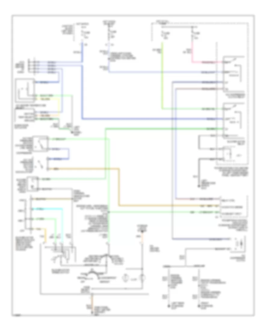
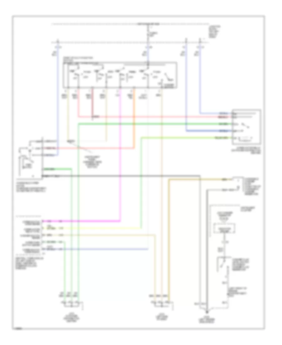
AIR CONDITIONING
Heater Wiring Diagram for Dodge Cab & Chassis R2002 3500
 https://portal-diagnostov.com/license.html
Automotive Electricians Portal FZCO
Automotive Electricians Portal FZCO
https://portal-diagnostov.com/license.html
https://portal-diagnostov.com/license.html
Automotive Electricians Portal FZCO
Automotive Electricians Portal FZCO
List of elements for Heater Wiring Diagram for Dodge Cab & Chassis R2002 3500:
- (dash panel right center support) g201
- (left fender side shield) g102
- Bi-level
- Blower motor (behind right side of dash)
- Blower motor relay
- Blower motor resistor block (behind right side of dash, on a/c-heater housing)
- Blower motor speed switch
- Defrost
- Floor
- Floor/defrost
- Fuse 10a
- Fuse 40a
- Heater control
- High
- Hot at all times
- Hot in run
- Illum
- Interior lights system
- J/c 1
- J/c 8 (behind center of dash)
- Junction block (left end of dash)
- Low
- Med 1
- Med 2
- Mode select switch
- Off
- Panel
- Power distribution center (in engine compartment, on left inner fender panel, near battery)
- S207 (dash harness, near blower motor)
- Tan
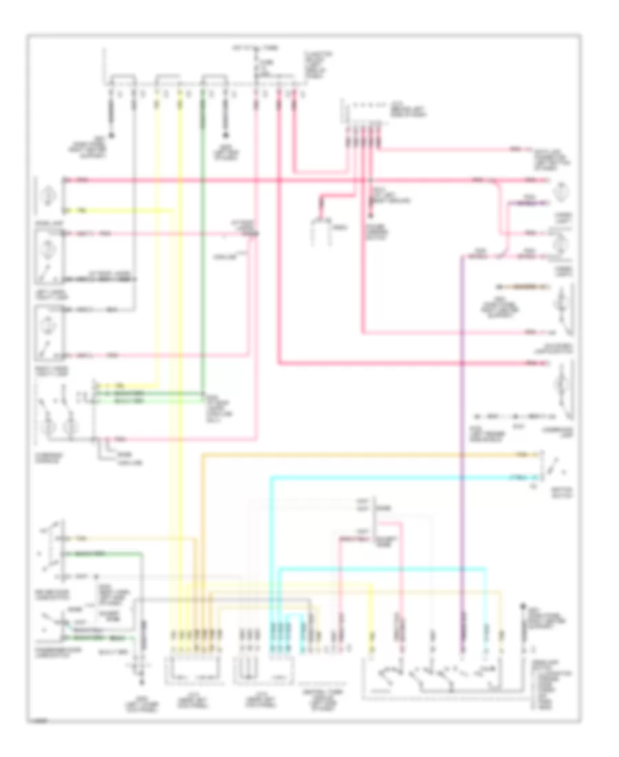
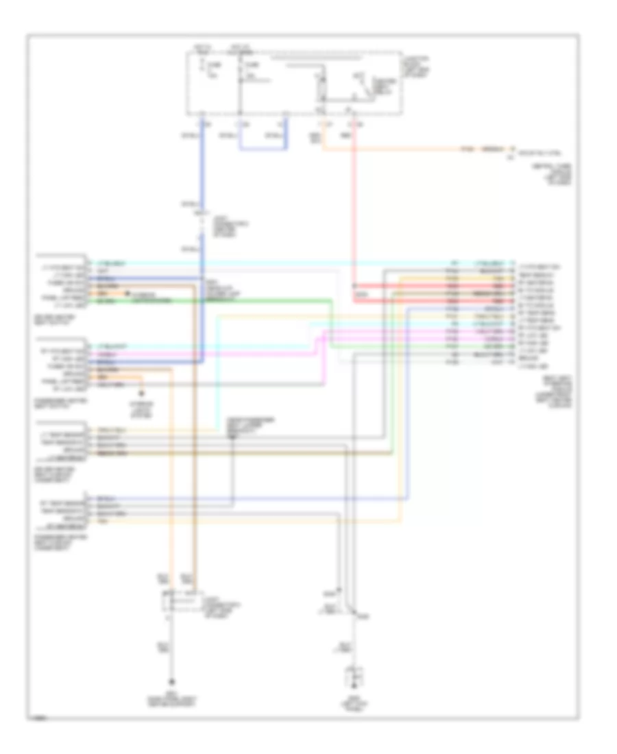
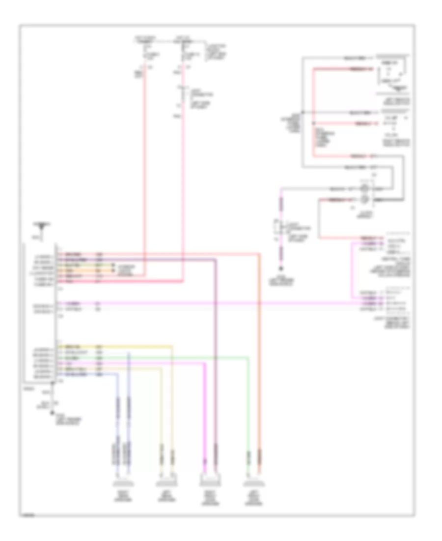
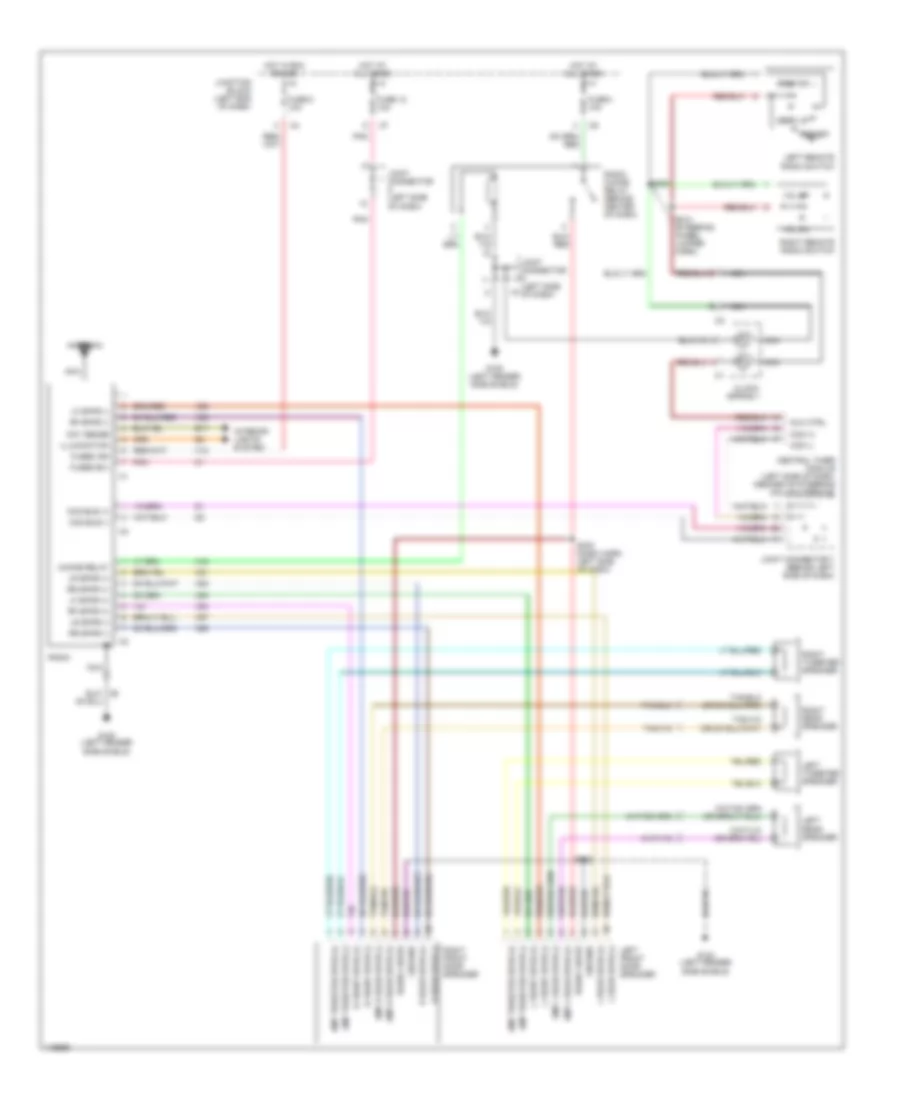
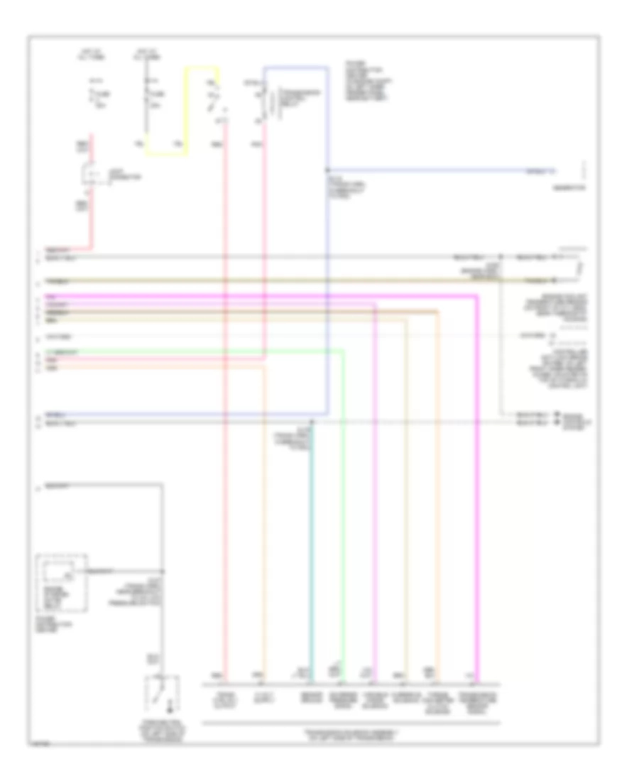
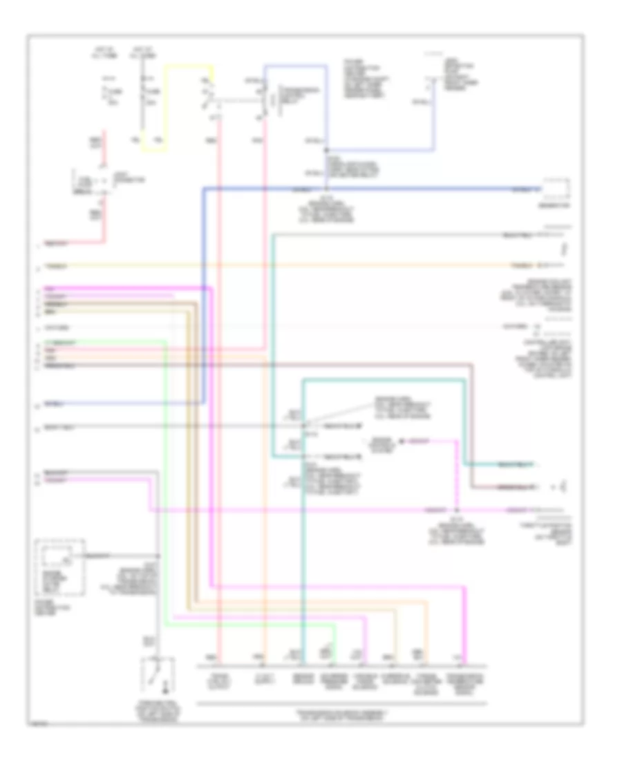
Manual A/C Wiring Diagram for Dodge Cab & Chassis R2002 3500
List of elements for Manual A/C Wiring Diagram for Dodge Cab & Chassis R2002 3500:
- (dash harness, near blower motor) s207
- (dash panel right center support) g201
- (engine harn., near break- out to fuel injectors) (8 cyl)
- (engine harness, near fuel transfer pump) s164
- (engine harness, top of transmission) (8 cyl) s122 (1o cyl) (engine harness, in breakout to transmission)
- (front of engine) g105
- (headlamp & dash harness, in power distribution center) s105
- (left fender side shield) g102
- (left rear of engine) g107
- A/c compressor clutch
- A/c compressor clutch relay
- A/c heater control
- A/c heater temperature select
- A/c high pressure switch (on discharge line, near a/c compressor)
- A/c low pressure switch (on top of a/c accumulator)
- A/c select input
- A/c switch sense
- A/c-high
- A/c-low
- A/c-med 1
- A/c-med 2
- Bi- level
- Blend door actuator
- Blower motor (behind right side of dash)
- Blower motor relay
- Blower motor resistor block (behind right side of dash, on a/c-heater housing)
- Blower motor speed switch
- C13
- C20
- C90
- Defrost
- Diesel
- Floor
- Floor/defrost
- Fuse 10a
- Fuse 40a
- Fuse j 10a
- Gasoline
- Ground
- Heater-high
- Heater-low
- Heater-med 1
- Heater-med 2
- High
- Hot at all times
- Hot in run
- Hot in run or start
- Ignition
- Illum
- Interior lights system
- J/c 1
- J/c 8 (behind center of dash)
- Junction block (left end of dash)
- Low
- Med 1
- Med 2
- Mode select switch
- Off
- Panel
- Power distribution center (in engine compartment, on left inner fender panel, near battery)
- Powertrain control module (pcm) (in engine compartment, on right side of firewall)
- Recirc
- Relay ctrl
- S120 (10 cyl (1), diesel (2)) ((1) engine harness, rear of engine) ((2) transmission harness, near breakout to a/c low pressure switch)
- Tan
- Temp select
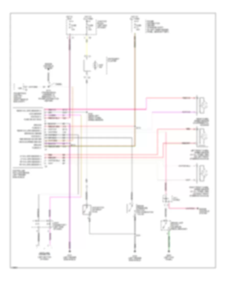
ANTI-LOCK BRAKES
Anti-lock Brake Wiring Diagrams for Dodge Cab & Chassis R2002 3500
List of elements for Anti-lock Brake Wiring Diagrams for Dodge Cab & Chassis R2002 3500:
- (left bottom of dash)
- 4wd ind
- 4wd sensor
- 4wd switch (on front axle)
- A10
- A20
- B113
- B114
- Brake lamp switch (on brake pedal bracket)
- Brake pressure switch (on combination valve)
- Brake sw sense
- Ccd bus (+)
- Ccd bus (-)
- Controller anti-lock brake (left fender side shield)
- Data link connector
- Diesel
- Engine controls system
- Fuse 10a
- Fuse 40a
- Fuse b (+)
- Fuse ign sw (run)
- G100 (left fender side shield)
- G101 (left fender side shield)
- G107
- G200 (left kick panel)
- Ground
- Hot at all times
- Hot in run
- Instrument cluster
- J/c 1 (in pdc)
- Joint connector 7 (left side of dash)
- Junction block (left end of dash)
- Left front wheel speed sensor (w/ all wheel abs) (on left front steering knuckle)
- Lf whl spd sensor (+)
- Lf whl spd sensor (-)
- Power distribution center (in engine compt, on left inner fender panel, near battery)
- Powertrain control module (right rear of eng compt)
- Rear wheel speed sensor (in differential housing)
- Rear whl spd sensor (+)
- Rear whl spd sensor (-)
- Red
- Red brake ind driver
- Rf whl spd sensor (+)
- Rf whl spd sensor (-)
- Right front wheel speed sensor (w/ all wheel abs) (on right front steering knuckle)
- S112
- S113
- S151
- S152 (near left front wheel speed sensor)
- S174 (transmission harness, in breakout to power distribution center)
- V40
- Vehicle speed sen sig
- Vss
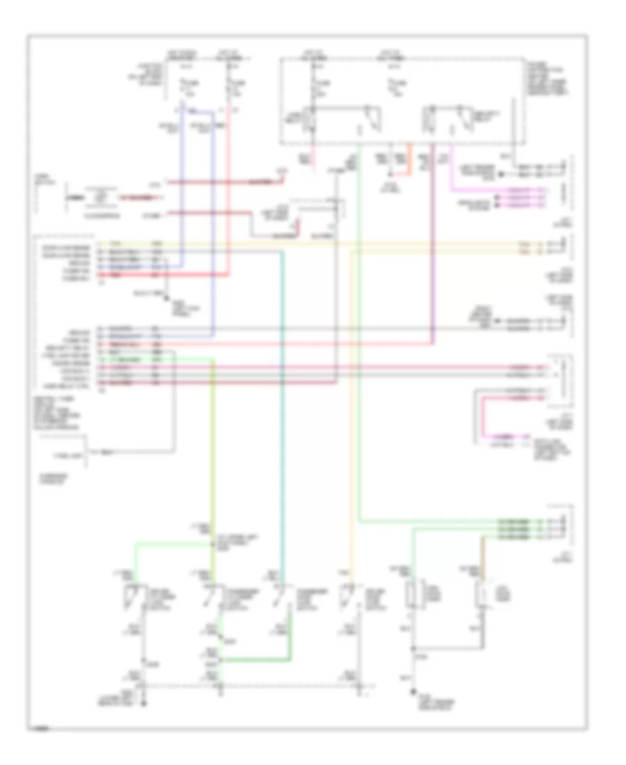
ANTI-THEFT
Anti-theft Wiring Diagram for Dodge Cab & Chassis R2002 3500
List of elements for Anti-theft Wiring Diagram for Dodge Cab & Chassis R2002 3500:
- (at upper left kick panel) s308
- (left fender side shield) g102
- (left side of dash) j/c 5
- (right center of dash) g201
- Ccd bus (+)
- Ccd bus (-)
- Central timer module (on left side of dash, inboard of steering column opening)
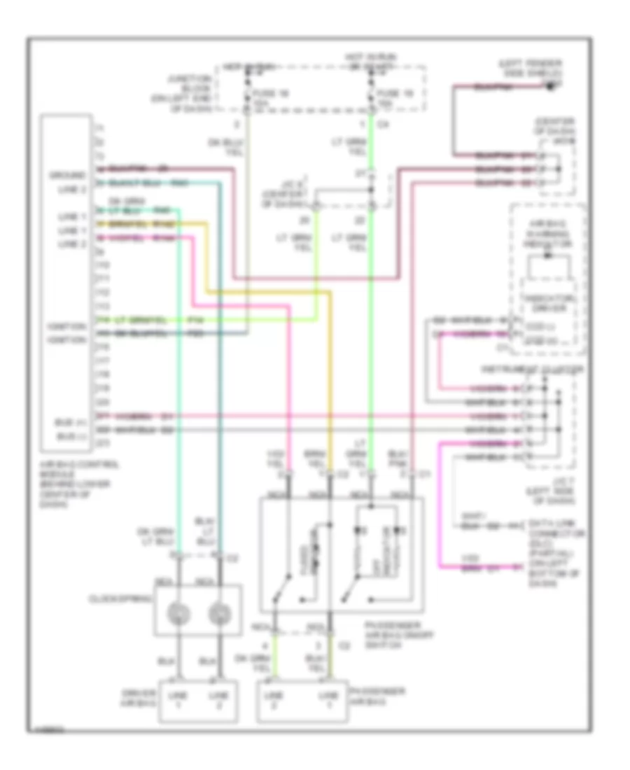
- Clockspring
- Ctm
- Data link connector (left bottom of dash)
- Disarm sense
- Door ajar sense
- Driver cylinder lock switch
- Driver door ajar switch
- F12
- Fuse 10a
- Fuse g 15a
- Fuse h 20a
- Fused b(+)
- Fused ign
- G100 (left fender side shield)
- G16
- G200 (left kick panel)
- G300 (lower left rear of cab)
- G50
- G69
- G73
- G75
- Ground
- Headlights system
- High note horn
- Horn relay
- Horn relay ctrl
- Horn switch
- Hot at all times
- Hot in run or start
- J/c 1 (in pdc)
- J/c 6 (left side of dash)
- J/c 7 (left side of dash)
- J/c 8 (left side of dash)
- Junction block (on left end of dash)
- Low note horn
- Nca
- Other
- Overhead console
- Passenger cylinder lock switch
- Passenger door ajar switch
- Power distribution center (on left inner fender panel, near battery)
- Red
- S143 (w/ drl)
- S150
- S305
- S329
- S330
- Security relay
- Tan
- Vtss lamp
- Vtss lamp driver
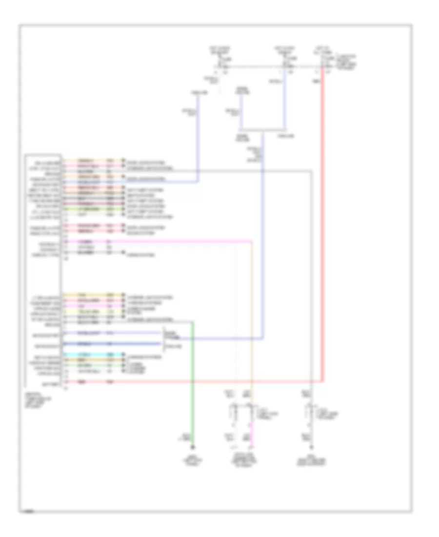
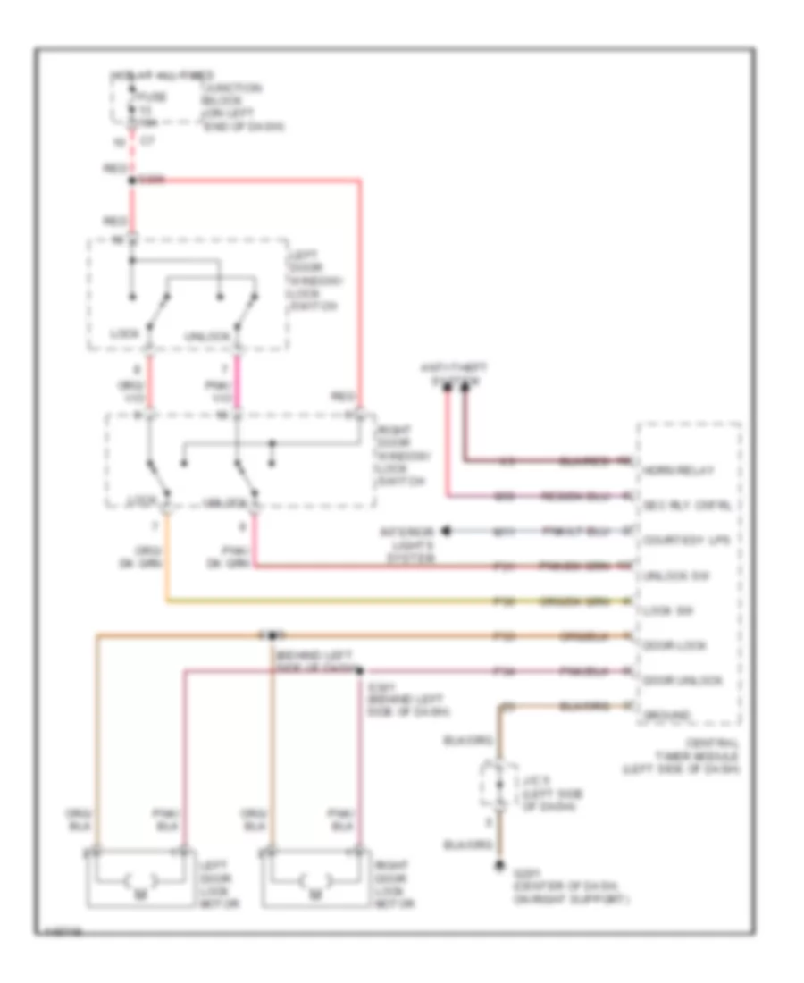
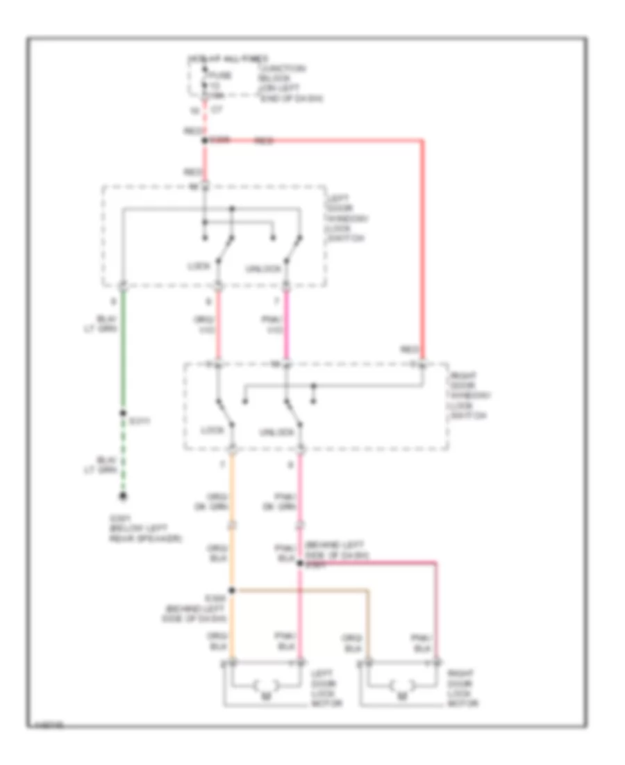
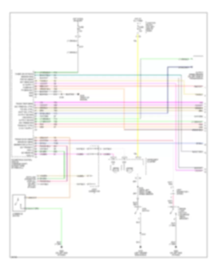
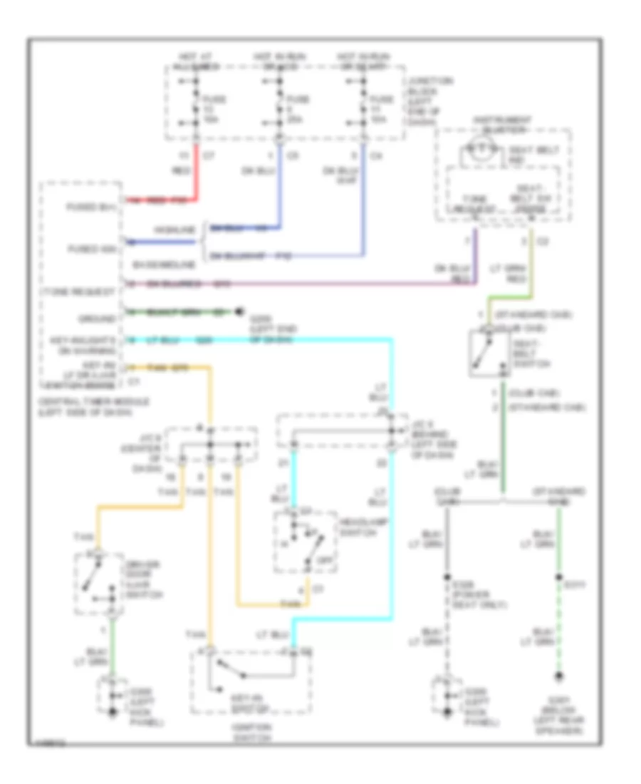
BODY COMPUTER
Body Computer Wiring Diagrams for Dodge Cab & Chassis R2002 3500
List of elements for Body Computer Wiring Diagrams for Dodge Cab & Chassis R2002 3500:
- Anti-theft system
- Base/ midline
- Battery
- Ccd bus (+)
- Ccd bus (-)
- Central timer module (left side of dash)
- Ctsy lp sw out
- Cyl lk sw mux
- Data link connector (left bottom of dash)
- Door locks system
- Dr lk driver
- Dr unlk drv
- F12
- F35
- Fuse 10a
- Fuse 25a
- G13
- G16
- G200 (left kick panel)
- G201 (right center dash support)
- G26
- G50
- G69
- G73
- G75
- Ground
- Heated seat sw
- Highline
- Horn rly ctrl
- Horns system
- Hot at all times
- Hot in acc or run
- Hot in run or start
- Ign run/accy
- Ign run/start
- Illum entry sw
- Interior lights system
- J/c 5 (left side of dash)
- J/c 7 (left kick panel)
- Junction block (left end of dash)
- Key-in ign sw
- Lt dr ajar sw
- M11
- M22
- P132
- P30
- P31
- P33
- P34
- Pass dr lk mtr
- Radio ctrl mux
- Red
- Rt dr ajar sw
- Seats system
- Secty rly ctrl
- Sound system
- Tan
- Tone reqst sig
- V10
- V18
- Vtss ind driver
- Warning systems
- Wiper/ washer system
- Wiper/washer system
- Wpr motor rly
- Wpr park sw
- Wpr sw mode
- Wpr sw sig
- Wshr sw sense
- X20
COMPUTER DATA LINES
Computer Data Lines for Dodge Cab & Chassis R2002 3500
List of elements for Computer Data Lines for Dodge Cab & Chassis R2002 3500:
- (behind left side of dash) j/c 7
- (diesel)
- (drain wire)
- (gas)
- (in breakout to engine control module) (diesel) s184
- (unterminated)
- A cummins bus (+)
- Air bag control module (behind lower center of dash)
- B cummins bus (-)
- Ccd bus (+)
- Ccd bus (-)
- Central timer module (on left side of dash)
- Controller anti-lock brake (rwal: left front inner fender) (4wabs: mounted on hydraulic control unit)
- Cummins bus (+)
- Cummins bus (-)
- Cummins bus (diesel) (left front of engine)
- Cummins bus shield
- D20
- D21
- D220
- Data link connector (dlc) (on left bottom of dash)
- Diesel
- Engine control module (on left side of engine, behind fuel filter)
- Fuse 12 10a
- G105 (front of engine)
- G107 (left rear of engine)
- G113 (primary battery engine ground)
- G200 (on left end of dash)
- Gas
- Ground
- Hot at all times
- Instrument cluster
- J/c 5 (behind left side of dash)
- Junction block (on left end of dash)
- K244
- K246
- K247
- Nca
- Overhead console (highline)
- Pnk
- Powertrain control module (on right side of firewall)
- Radio
- S109
- S126
- S164
- S172 (diesel) (top of a/c accumulator)
- S173 (diesel) (top of a/c accumulator)
- S175 (diesel) (in breakout to pdc)
- Sci receive
- Sci transmit
- Z11
- Z12
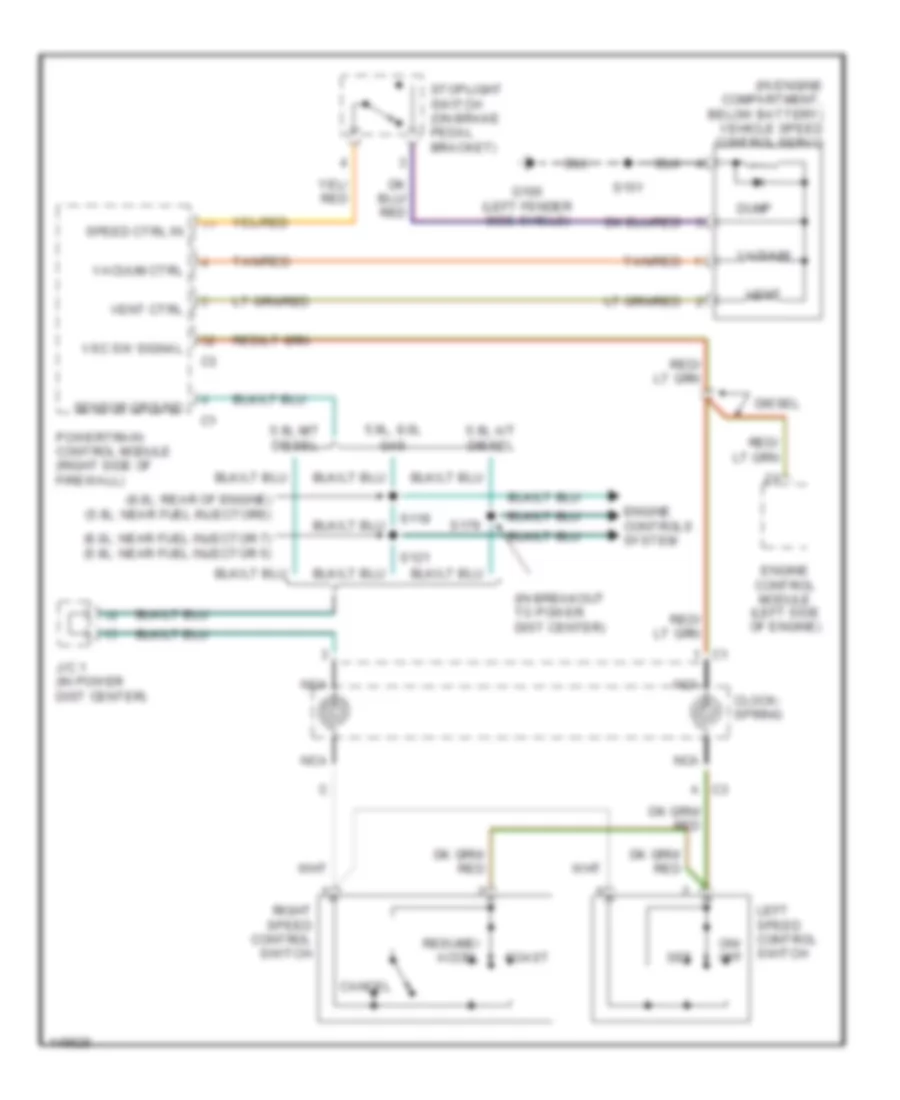
CRUISE CONTROL
Cruise Control Wiring Diagram for Dodge Cab & Chassis R2002 3500
List of elements for Cruise Control Wiring Diagram for Dodge Cab & Chassis R2002 3500:
- (8.0l: near fuel injector 7) (5.9l: near fuel injector 5)
- (8.0l: rear of engine) (5.9l: near fuel injectors)
- (in breakout to power dist center)
- (in engine compartment, below battery) vehicle speed control servo
- 5.9l a/t diesel
- 5.9l m/t diesel
- 5.9l, 8.0l
- C3 a
- Cancel
- Clock- spring
- Coast
- Diesel
- Dump
- Engine control module (left side of engine)
- Engine controls system
- G100 (left fender side shield)
- Gas
- J/c 1 (in power dist center)
- Left speed control switch
- Nca
- On/ off
- Powertrain control module (right side of firewall)
- Resume/ accel
- Right speed control switch
- S118
- S121
- S151
- S179
- Sensor ground
- Set
- Speed ctrl in
- Stoplight switch (on brake pedal bracket)
- Tan/red
- Vacuum
- Vacuum ctrl
- Vent
- Vent ctrl
- Vsc sw signal
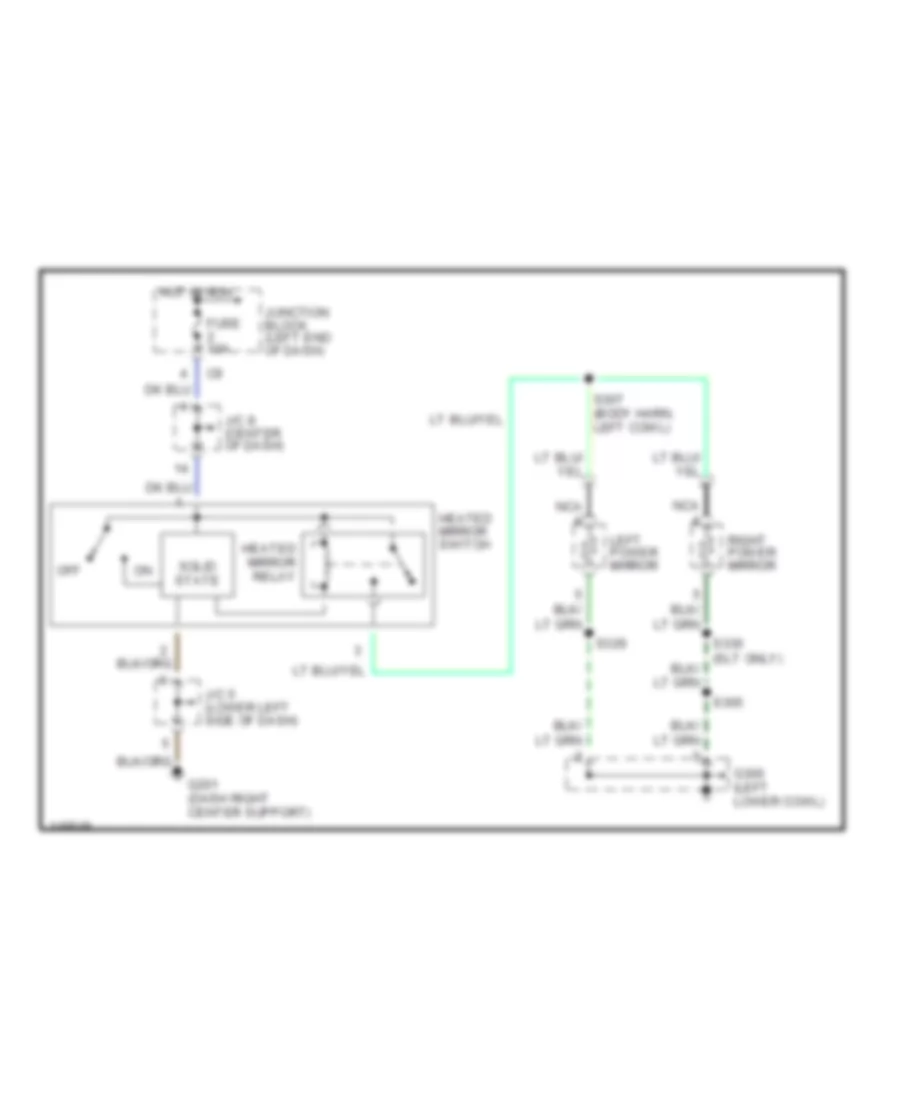
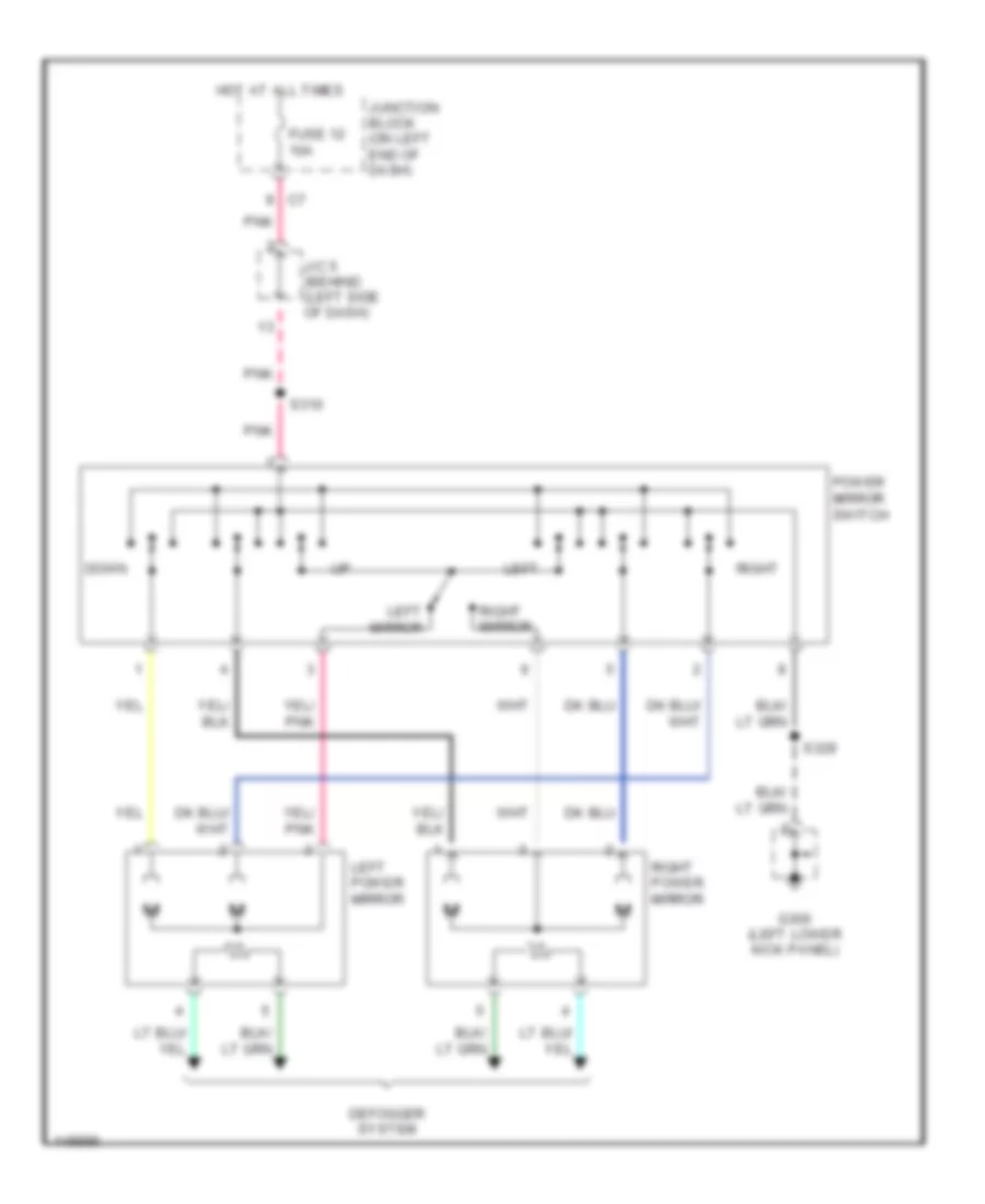
DEFOGGERS
Heated Mirrors Wiring Diagram for Dodge Cab & Chassis R2002 3500
List of elements for Heated Mirrors Wiring Diagram for Dodge Cab & Chassis R2002 3500:
- Fuse 10a
- G201 (dash right center support)
- G300 (left lower cowl)
- Heated mirror relay
- Heated mirror switch
- Hot in run
- J/c 5 (lower left side of dash)
- J/c 8 (center of dash)
- Junction block (left end of dash)
- Left power mirror
- Nca
- Off
- Right power mirror
- S305
- S307 (body harn, left cowl)
- S329
- S330 (slt only)
- Solid state
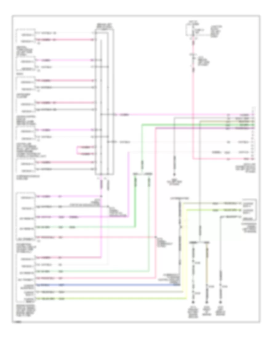
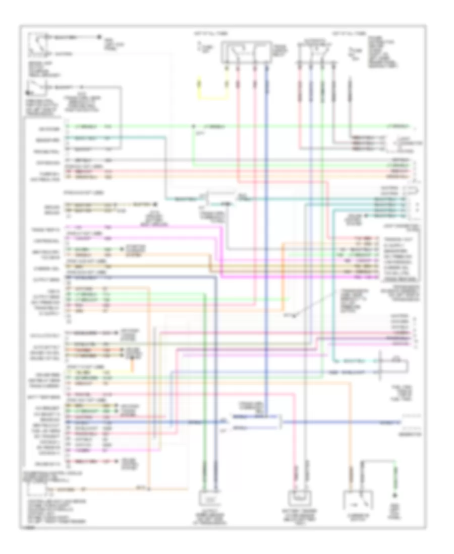
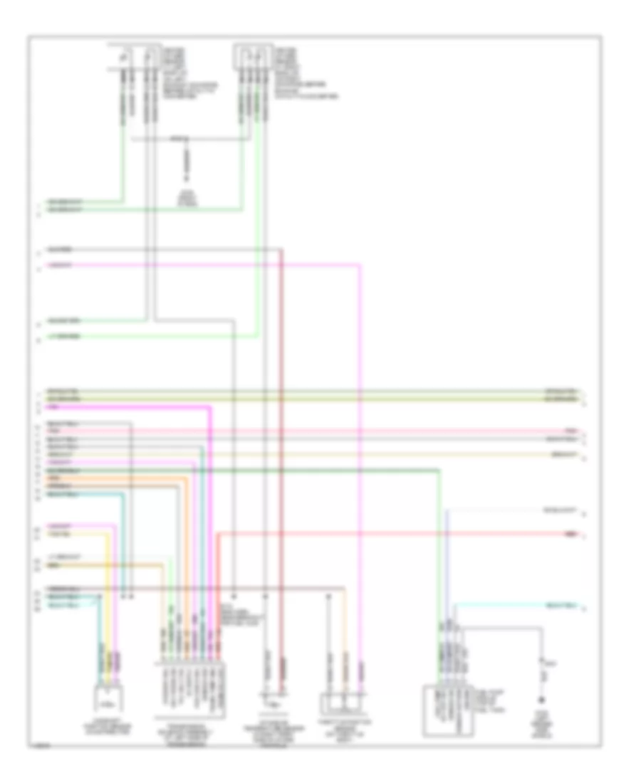
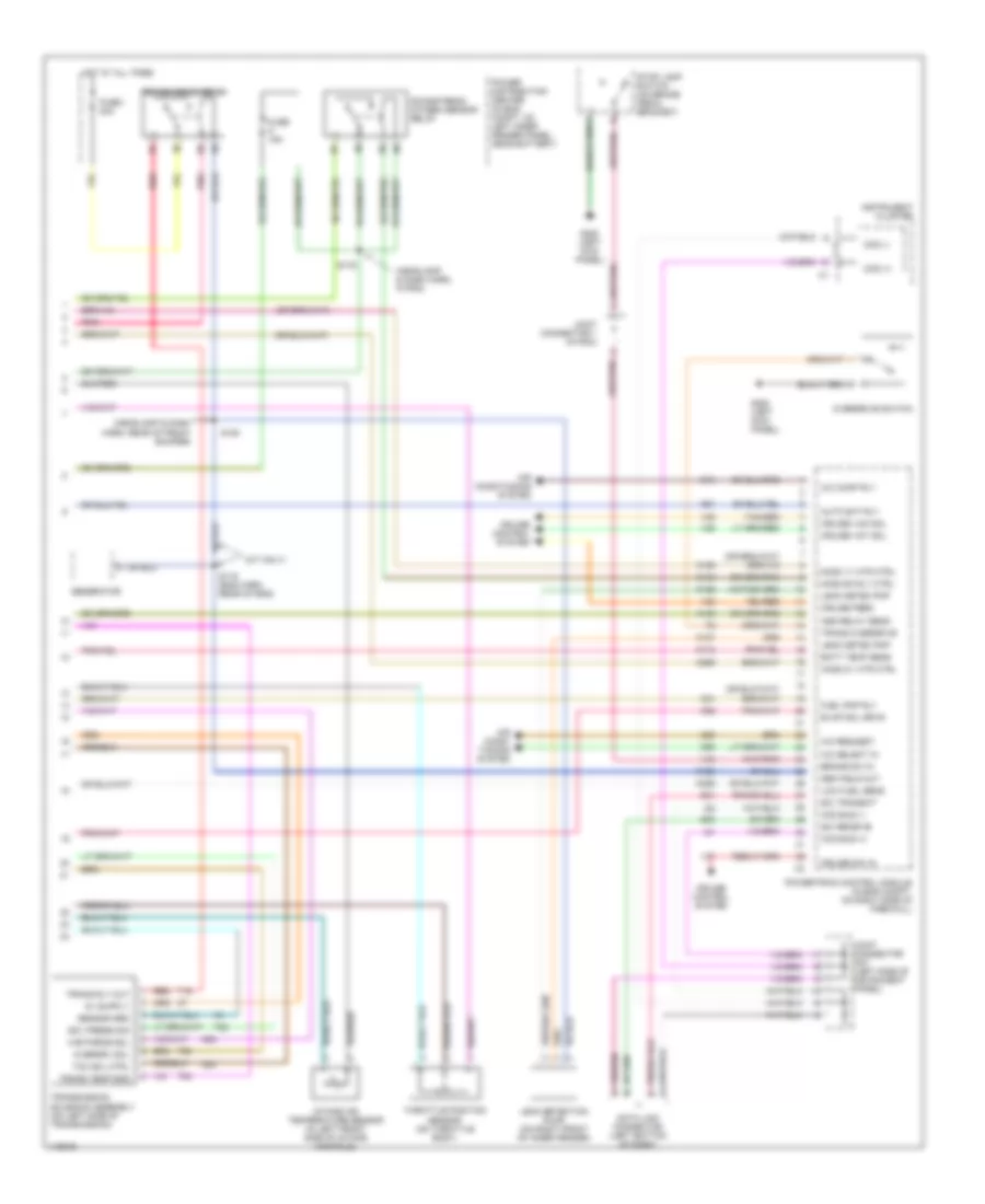
ENGINE PERFORMANCE
5.9L
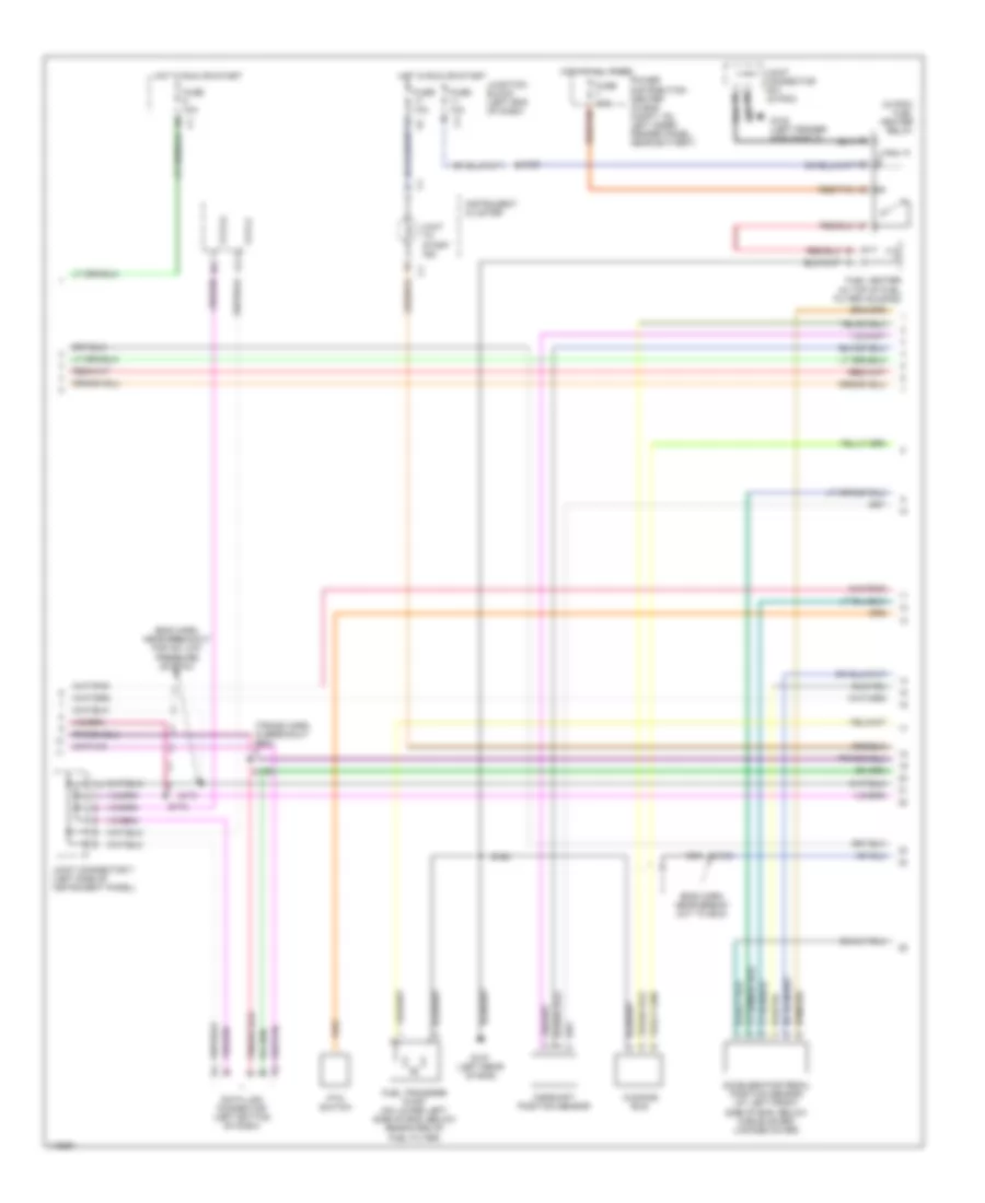
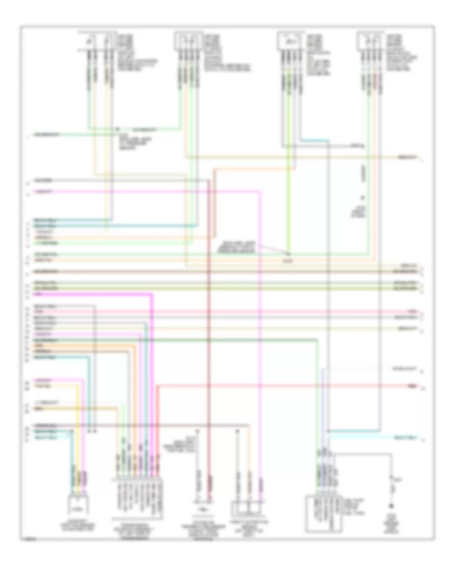
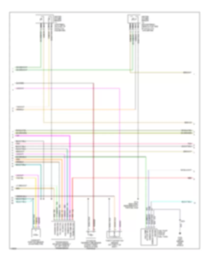
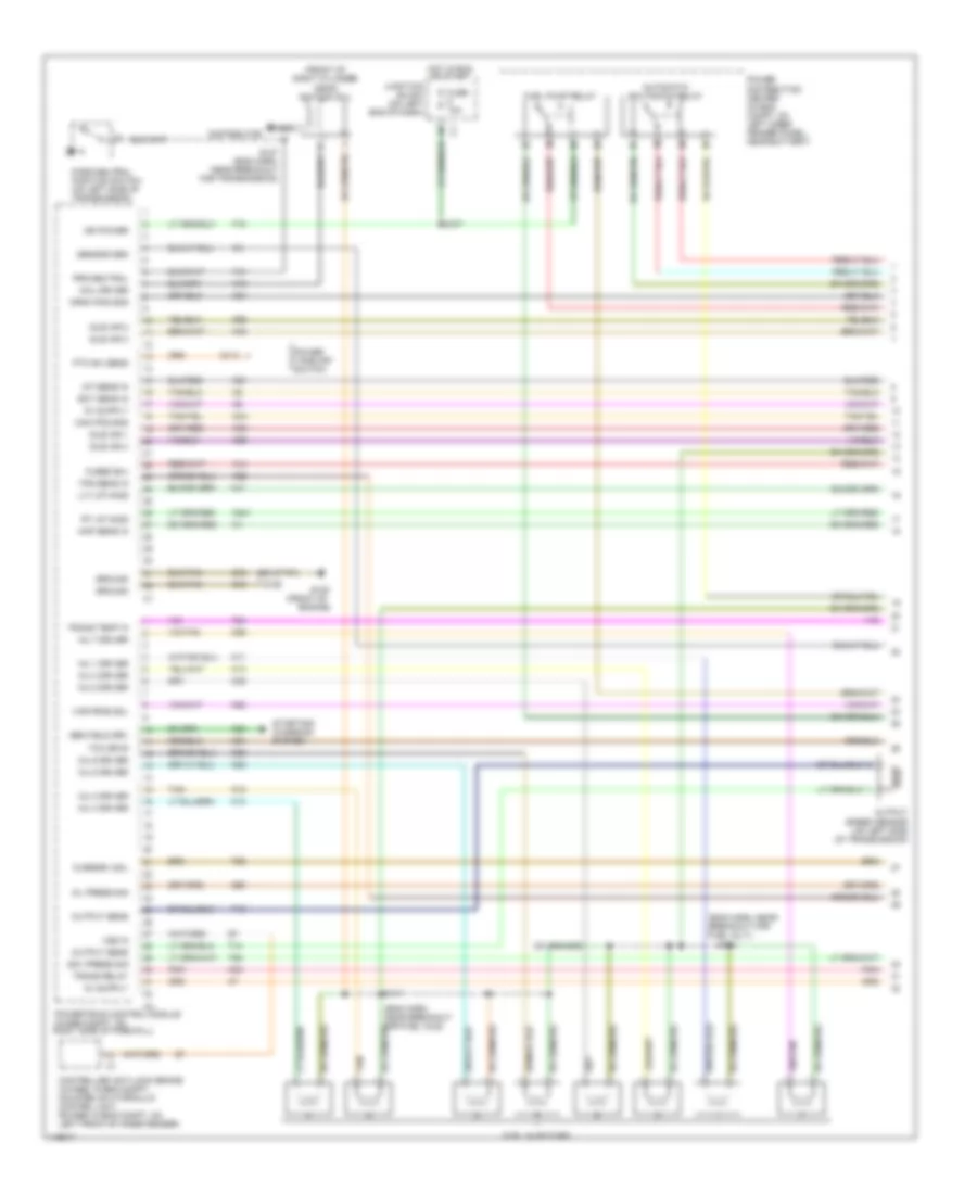
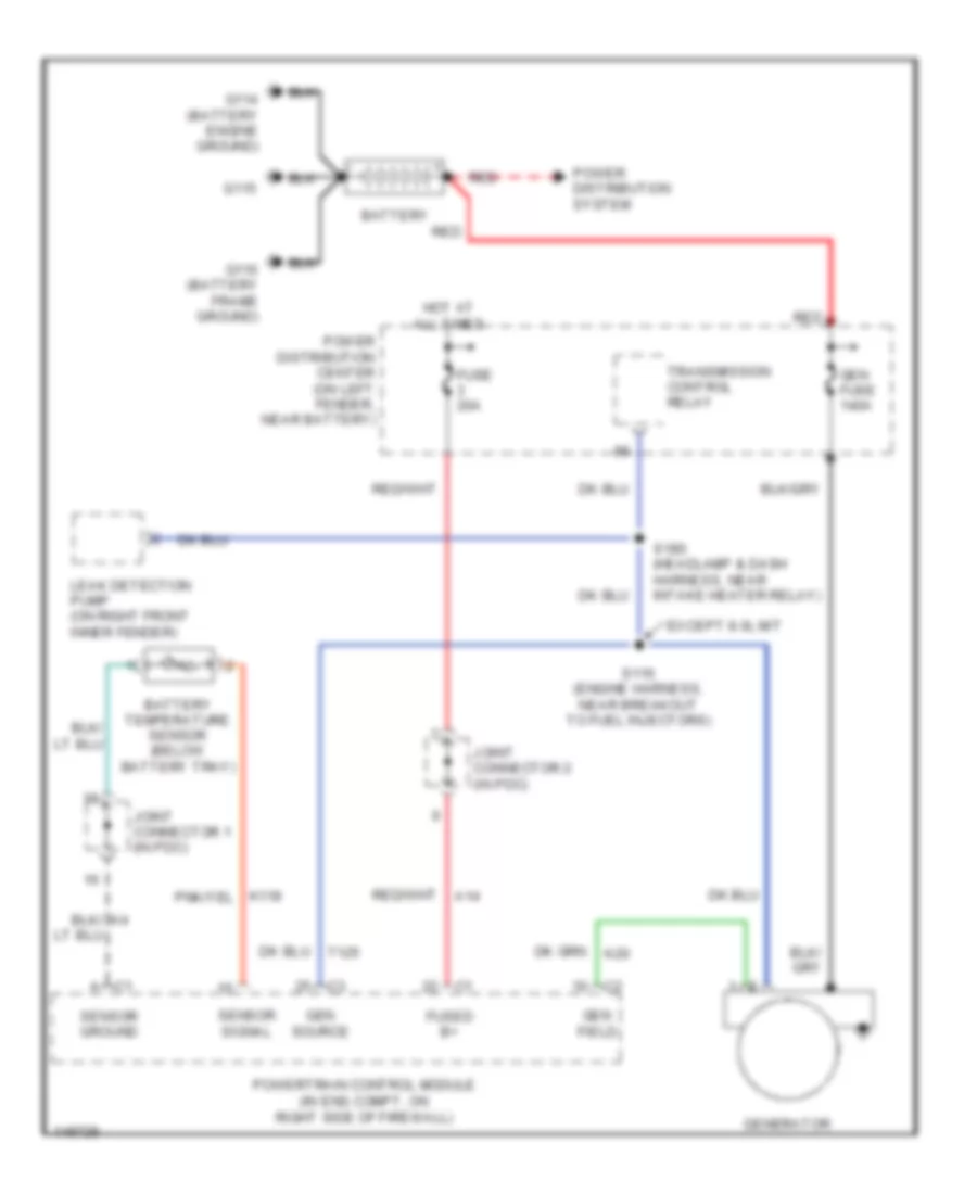
5.9L 24-Valve Diesel, Engine Performance Wiring Diagrams (1 of 3) for Dodge Cab & Chassis R2002 3500
List of elements for 5.9L 24-Valve Diesel, Engine Performance Wiring Diagrams (1 of 3) for Dodge Cab & Chassis R2002 3500:
- (pins 12-20 not used)
- (pins 16-21 not used)
- (pins 2-7 not used)
- (pins 22-24 not used)
- (pins 24-30 not used)
- (pins 7-10 not used)
- (pins 9-21 not used)
- (trans harn, in breakout pdc) s116
- (trans harn, in breakout to pdc)
- (transmission harn, near breakout to a/c low pressure switch)
- A/c clutch rly
- A/c request
- A/c select in
- A/t
- A14
- A142
- Acc pedal pos
- Air condi- tioning system
- Asd relay sens
- Auto sht rly
- Automatic shutdown relay
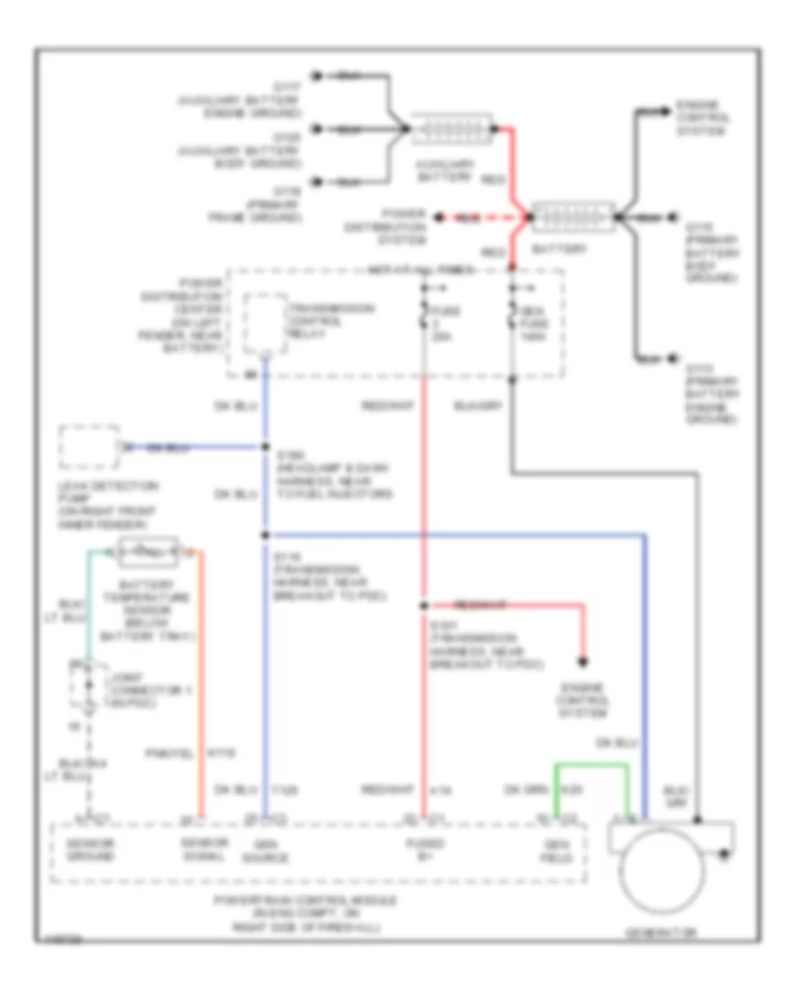
- Batt temp sens
- Battery temper- ature sensor (below battery tray)
- Brake lamp switch (on brake pedal bracket)
- Brake sw
- C13
- C20
- C90
- Ccd bus (+)
- Ccd bus (-)
- Ckp eng sig
- Controller anti-lock brake (4wabs: in eng compt, mounted on hydraulic control unit; rwabs: in eng compt, on left front inner fender)
- Cruise control system
- Cruise feed
- Cruise sw in
- Cruise vac sol
- Cruise vnt sol
- D21
- D220
- F18
- Fuel lev sens
- Fuel tank module (top of fuel tank)
- Fuse 30a
- Fuse i 20a
- Fused b(+)
- G115 (primary battery body ground)
- G200 (left kick panel)
- Gen field drv
- Gen field out
- Generator
- Gov press sig
- Ground
- Hot at all times
- Ign power
- Joint connector (in pcd)
- Joint connector 1 (in pdc)
- K118
- K20
- K22
- K226
- K24
- K30
- K51
- K54
- K88
- M/t
- Output sens
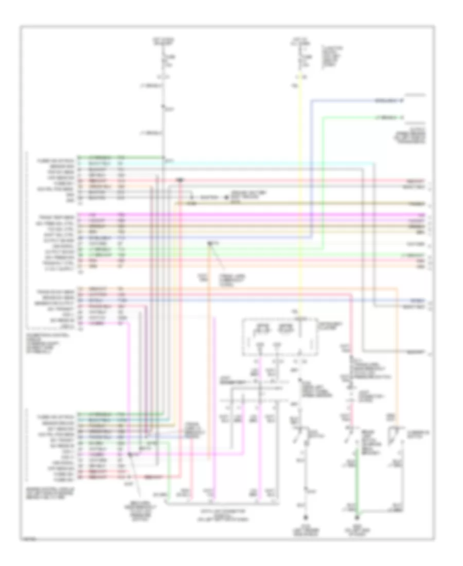
- Output speed sensor (on left side of transmission)
- Overdrive switch
- Overdrv sol
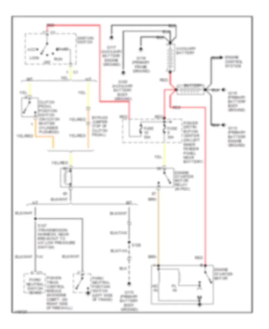
- Park/neutral position switch (on left side of transmission)
- Pnk
- Power distribution center (in eng compt, on left inner fender panel, near battery)
- Powertrain control module (in eng compt, on right side of firewall)
- Prk/neutral
- Red
- S111
- S126
- S127 (trans harn, near breakout to park/neutral position switch)
- S171
- S174
- S179
- Sci receive
- Sci transmit
- Sensor grd
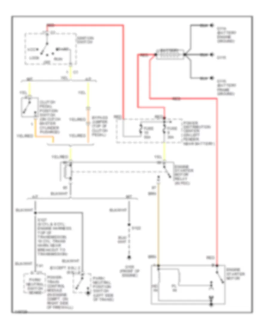
- Starting/ charging system
- T125
- T13
- T14
- T16
- T25
- T41
- T54
- T60
- Tan/red
- Tcc drvr
- Tcc sol ctrl
- Trans overdrv
- Trans relay
- Trans rly out
- Trans temp in
- Trans temp sns
- Trans- mission relay
- Transmission solenoid assembly (on left side of transmission)
- V32
- V35
- V36
- V37
- V40
- Var force sol
- Var frce sol
- Vss in
- Z12
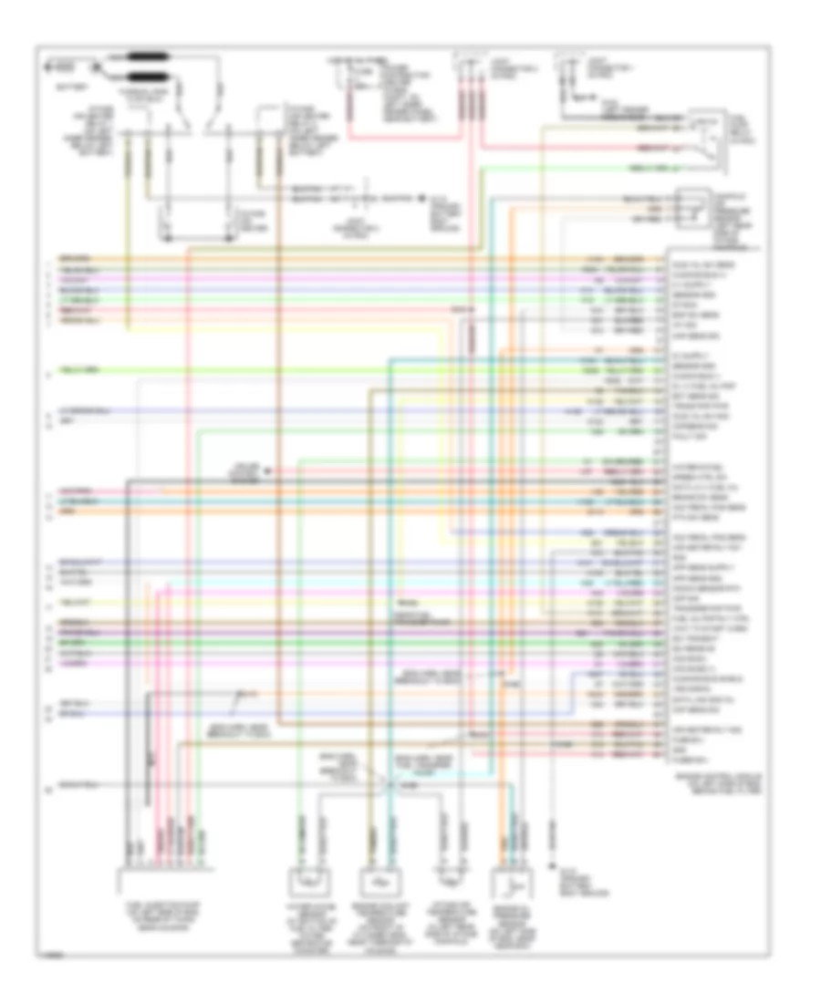
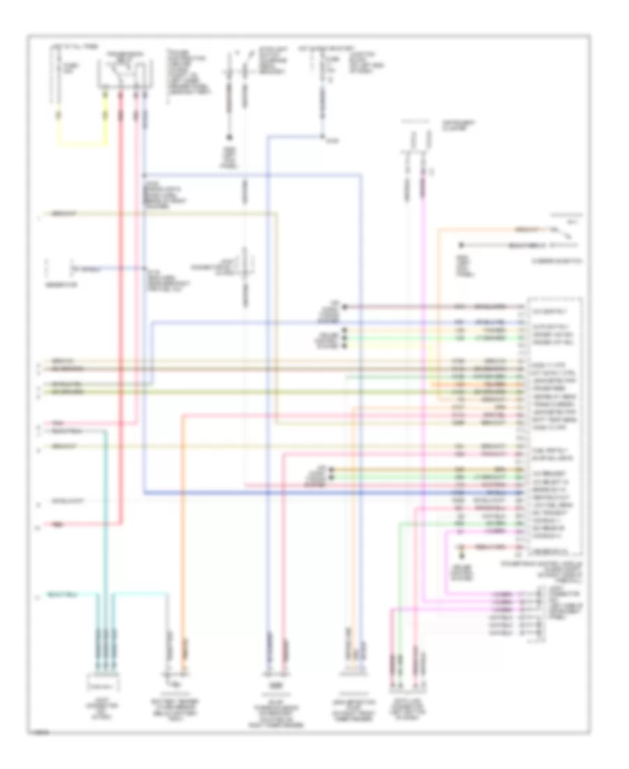
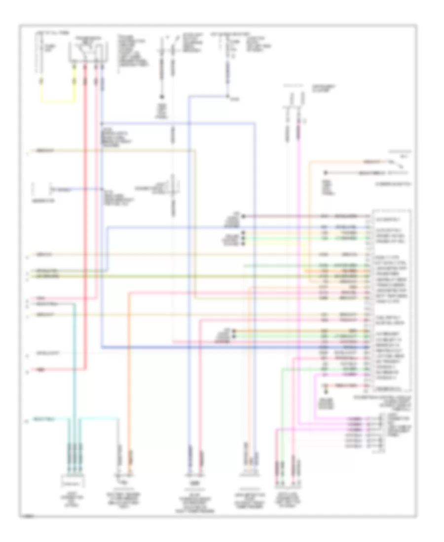
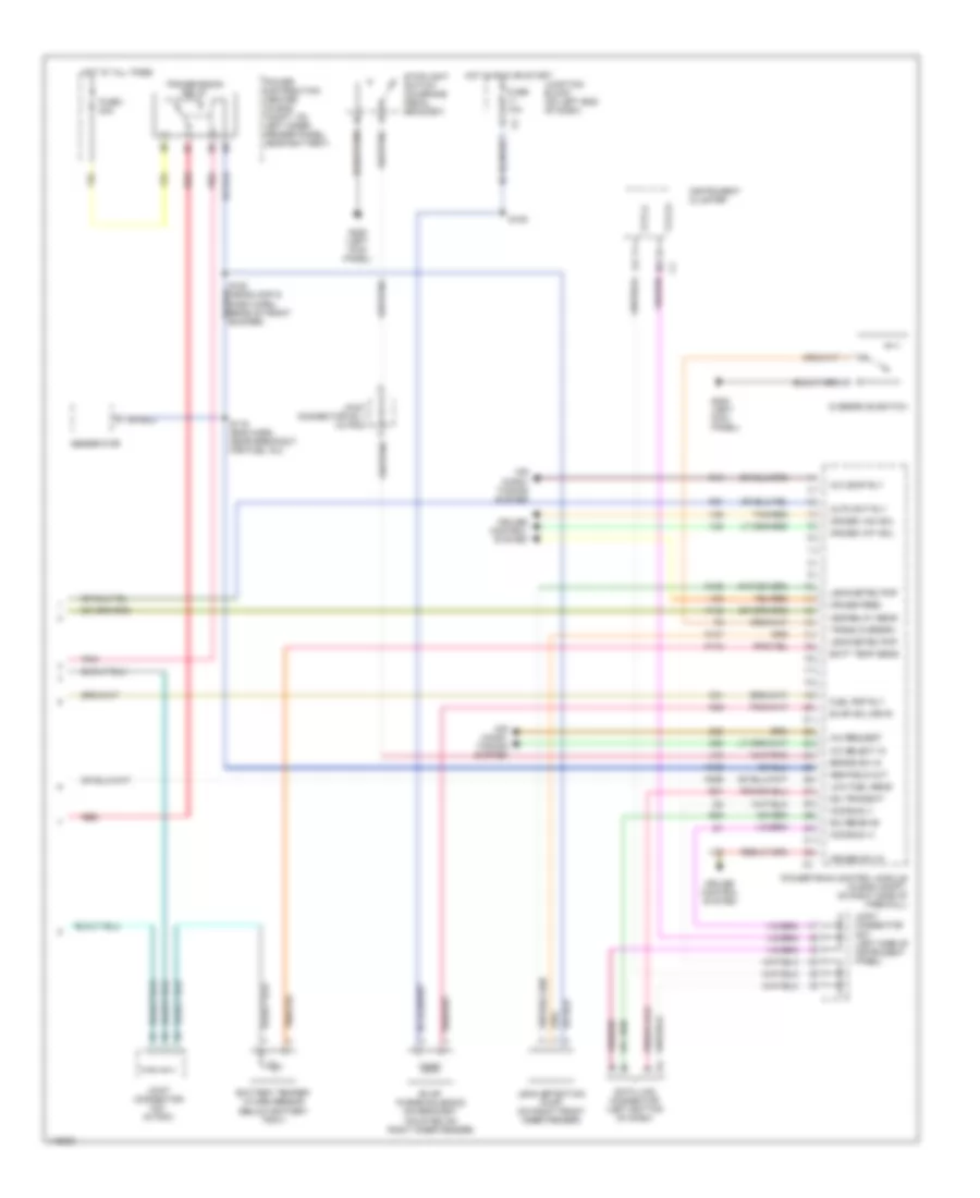
5.9L 24-Valve Diesel, Engine Performance Wiring Diagrams (2 of 3) for Dodge Cab & Chassis R2002 3500
List of elements for 5.9L 24-Valve Diesel, Engine Performance Wiring Diagrams (2 of 3) for Dodge Cab & Chassis R2002 3500:
- (eng harn, near break- out to ecm)
- (eng harn, near breakout for a/c low pressure switch)
- (in pdc) fuel heater relay
- (trans harn, in breakout pdc)
- Accelerator pedal position sensor (at left front side of eng, below cable/lever/ linkage cover)
- Camshaft position sensor
- Ccd (+)
- Ccd (-)
- Cummins bus
- Data link connector (left bottom of dash)
- Fuel heater (in top of fuel filter housing)
- Fuel transfer pump (on lower left side of eng, below rearward of fuel filter)
- Fuse 10a
- Fuse 40a
- G102 (left fender side shield)
- G107 (left rear of eng)
- Hot at all times
- Hot in run or start
- Instrument cluster
- Joint connector 7 (left side of instrument panel)
- Joint connector no1 (in pdc)
- Junction block (left end of dash)
- Nca
- Power distribution center (in eng compt, on left inner fender panel, near battery)
- Pto switch
- Red/tan
- S105
- S164
- S172
- S173
- S175
- S184
- Wait to start ind
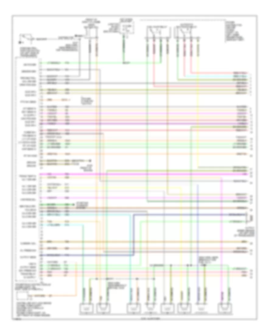
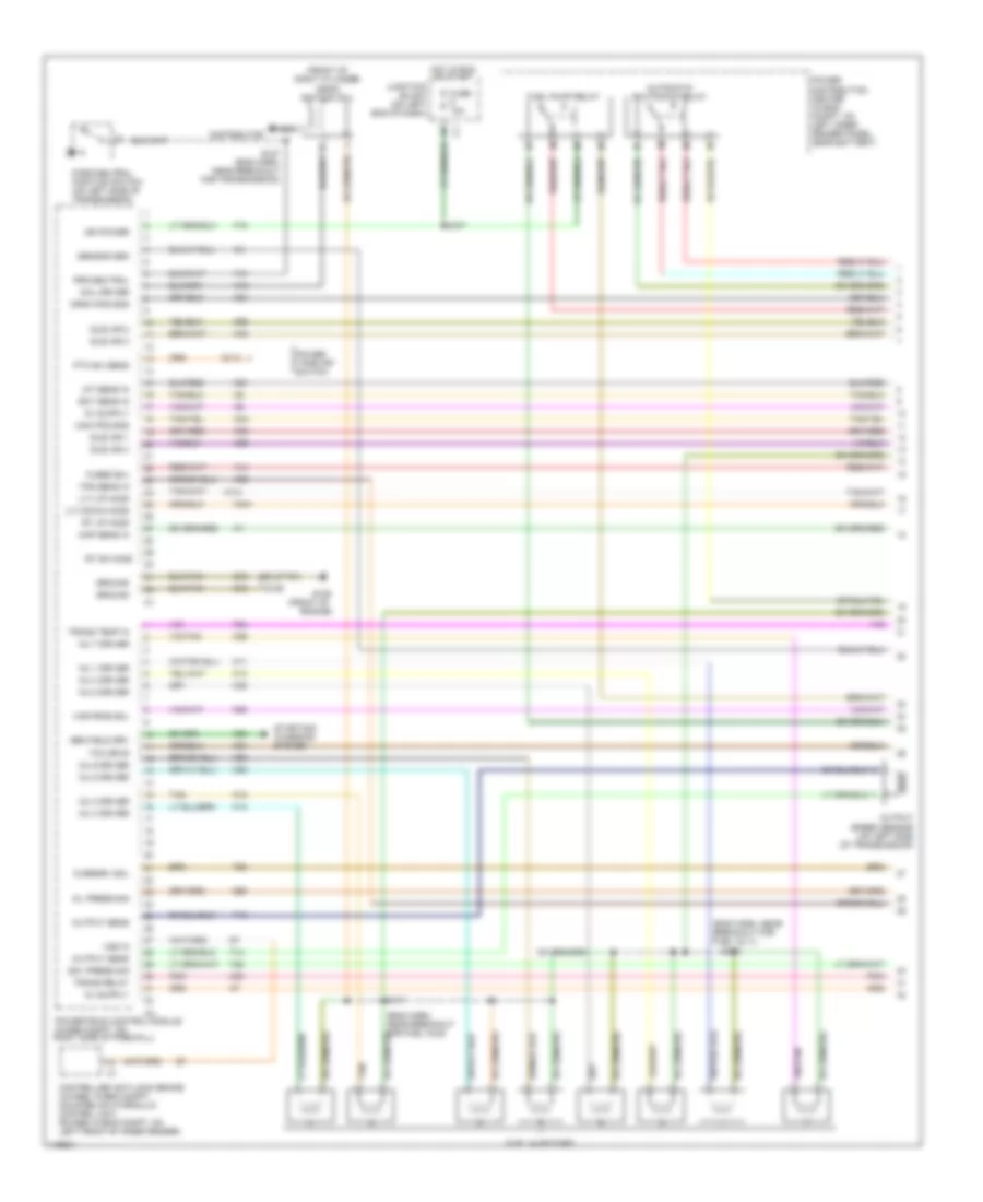
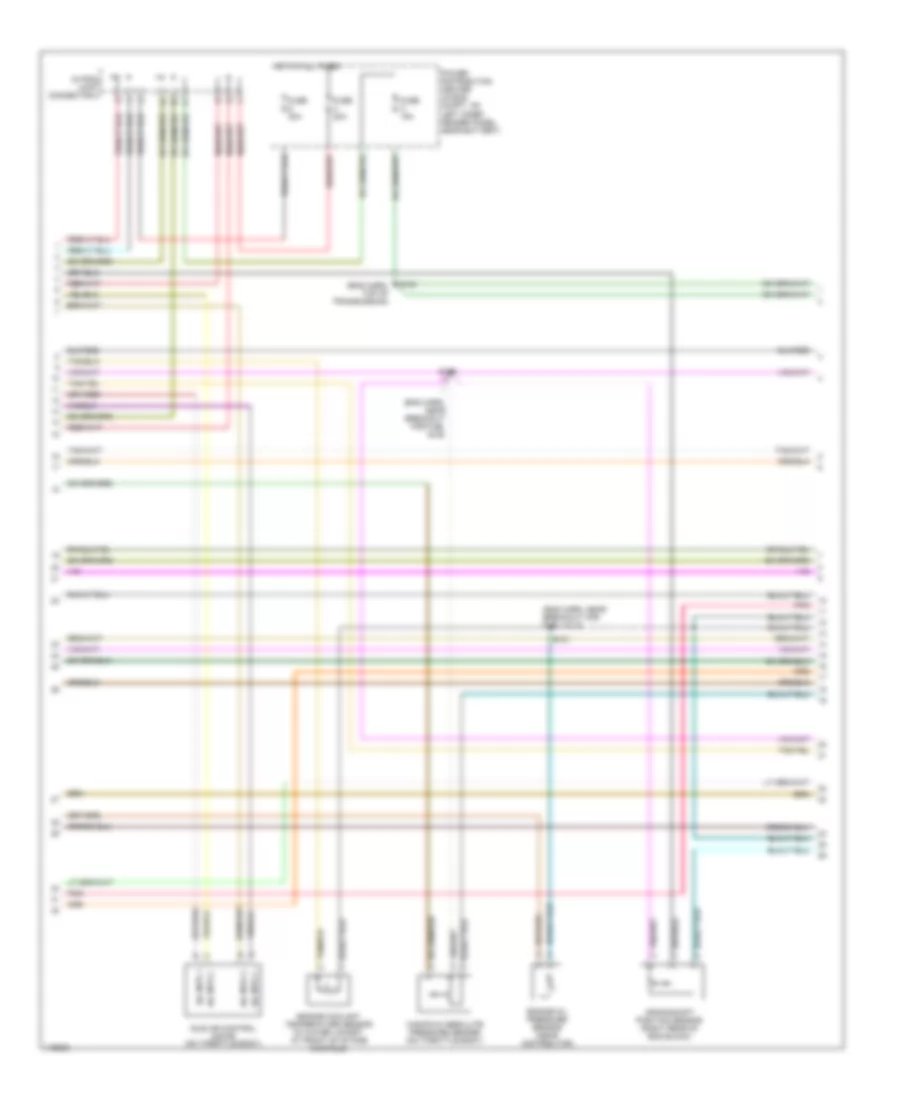
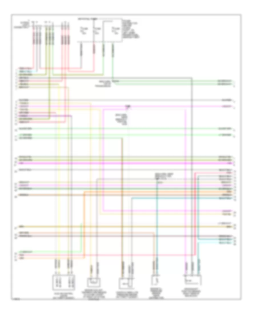
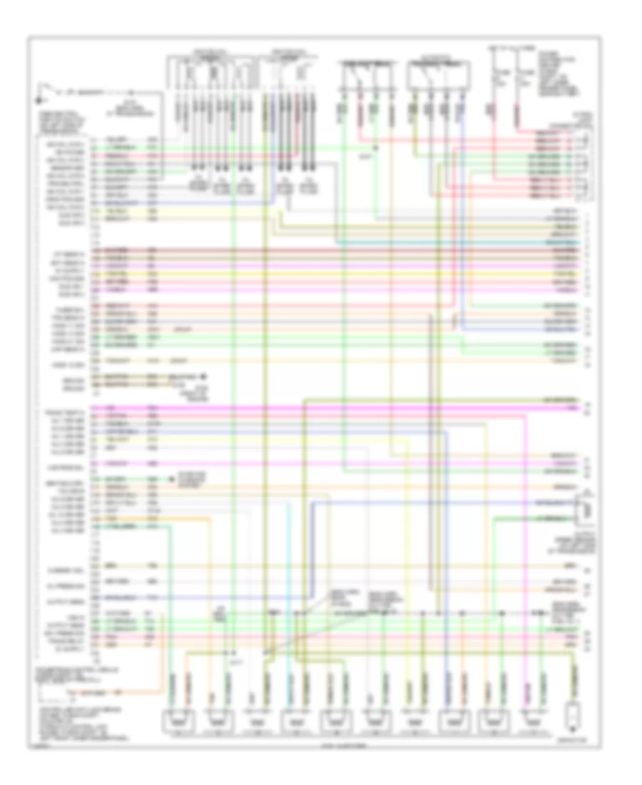
5.9L 24-Valve Diesel, Engine Performance Wiring Diagrams (3 of 3) for Dodge Cab & Chassis R2002 3500
List of elements for 5.9L 24-Valve Diesel, Engine Performance Wiring Diagrams (3 of 3) for Dodge Cab & Chassis R2002 3500:
- (eng harn, near breakout to ecm)
- (eng harn, near fuel transfer pump)
- (near fuel transfer pump)
- A14
- Acc pedal pos sens
- Air heater rly no1
- Air heater rly no2
- App sens gnd
- Battery
- Brake sw sens
- Ccd bus(-)
- Ccd buss (+)
- Ckp sens sig
- Cmp sig
- Cmpsens sig
- Cruise control system
- Cummin bus (-)
- Cummins bus (+)
- Cummins bus shield
- D20
- D21
- Data link shd inj
- Data lk (-) fuel inj
- Dl (+) fuel inj pmp
- Ect sens sig
- Engine control module (on left side of eng, behind fuel filter)
- Engine coolant temperature sensor (on front of cylinder head, near thermostat housing)
- Engine oil pressure sensor (on left side of eng, near near ecm)
- Eop sw sens
- F18
- Fault sig
- Fuel inj pmp rly ctrl
- Fuel injection pump (on left side of eng, on rear of timing gear housing)
- Fuel pump relay (in pdc)
- Fuse 20a
- Fuse b(+)
- Fused b(+)
- G10
- G102 (left fender side shield)
- G113
- G115 (primary battery body ground)
- G12
- G85
- Gnd
- H101
- H102
- H103
- H104
- H105
- Hot at all times
- Iat sig
- Idle val sw no2
- Idle val sw sens
- Intake air heater
- Intake air heater relay 1 (on left inner fender, below left battery)
- Intake air heater relay 2 (on left inner fender, below left battery)
- Intake air temperature sensor (in left rear side of intake manifold)
- Joint connector 1 (in pdc)
- Joint connector 2 (in pdc)
- K104
- K124
- K131
- K135
- K14
- K21
- K22
- K24
- K240
- K242
- K243
- K244
- K246
- K247
- K44
- K45
- K48
- Knock sensor rtn
- Manifold air pressure sensor (left rear side of intake manifold)
- Map sens sig
- Nca
- Power distribution center (in eng compt, on left inner fender panel, near battery)
- Pto sw sens
- S160
- S161
- S165
- S166
- S167
- S168
- S170
- S21
- S22
- Sci receive
- Sci transmit
- Sensor gnd
- Speed ctrl sw
- St-run
- Trans pmp pwr
- Transfer pmp pwr
- V32
- V37
- Vss signal
- Wait to start warn
- Water in-fuel sensor (at bottom of fuel filter/ water separator canister)
- Water-in-fuel
- Z12
5.9L, Engine Performance Wiring Diagrams, California (1 of 4) for Dodge Cab & Chassis R2002 3500
List of elements for 5.9L, Engine Performance Wiring Diagrams, California (1 of 4) for Dodge Cab & Chassis R2002 3500:
- (eng harn, near breakout for fuel inj 3 )
- (eng harn, near breakout for fuel injs)
- (front of
- (front of right cylinder head) ignition coil
- (lt) down ho2s
- (lt) up ho2s
- A14
- Automatic shutdown relay
- Cam pos sns
- Coil driver
- Controller anti-lock brake (4wabs: in eng compt, mounted on hydraulic control unit; rwabs: in eng compt, on left front of inner fender)
- Crnk pos sns
- Distributor
- Ect sens in
- Engine)
- F18
- Fuel injectors
- Fuel pump relay
- Fuse 10a
- Fused b(+)
- G105
- G113
- G60
- Gen field drv
- Gov press sig
- Ground
- Hot in run or start
- Iat sens in
- Idle air 1
- Idle air 2
- Idle air 3
- Idle air 4
- Ign power
- Inj 1 driver
- Inj 2 driver
- Inj 3 driver
- Inj 4 driver
- Inj 5 driver
- Inj 6 driver
- Inj 7 driver
- Inj 8 driver
- Junction block (on left end of dash)
- K11
- K12
- K13
- K14
- K141
- K19
- K20
- K21
- K22
- K24
- K241
- K26
- K28
- K30
- K341
- K38
- K39
- K40
- K44
- K441
- K54
- K58
- K59
- K60
- K88
- Map sens in
- Nca
- Oil press sig
- Output sens
- Output speed sensor (on left side of transmission)
- Overdrv sol
- Park/neutral position switch (on left side of transmission)
- Pnk
- Power distribution center (in eng compt, on left inner fender panel, near battery)
- Power take off switch
- Powertrain control module (in eng compt, on right side of firewall)
- Prk/neutral
- Pto sw sens
- Rt dn ho2s
- Rt up ho2s
- S107
- S117
- S123
- S126
- S127 (eng harn, near breakout for transmission)
- Sensor grd
- Starting/ charging system
- T13
- T14
- T25
- T41
- T54
- T60
- Tan
- Tcc drvr
- Tps sens in
- Trans relay
- Trans temp in
- Var frce sol
- Vss in
- Z12
5.9L, Engine Performance Wiring Diagrams, California (2 of 4) for Dodge Cab & Chassis R2002 3500
List of elements for 5.9L, Engine Performance Wiring Diagrams, California (2 of 4) for Dodge Cab & Chassis R2002 3500:
- (eng harn, near breakout for fuel inj 5)
- (eng harn, near breakout for fuel injs)
- (headlamp & dash harn, in pdc)
- (in pdc) joint connector 2
- Crankshaft position sensor (right rear of eng block)
- Engine coolant temperature sensor (in water jacket, at front of intake manifold)
- Engine oil pressure sensor (near distributor)
- Fuse 20a
- Fuse 30a
- Fuse k 15a
- Hot at all times
- Iac mtr 1
- Iac mtr 2
- Iac mtr 3
- Iac mtr 4
- Idle air control motor (on throttle body)
- Manifold absolute pressure sensor (on throttle body)
- Oxygen sensor downstream relay
- Pnk
- Power distribution center (in eng compt, on left inner fender panel, near battery)
- S119
- S121
- S176
5.9L, Engine Performance Wiring Diagrams, California (3 of 4) for Dodge Cab & Chassis R2002 3500
List of elements for 5.9L, Engine Performance Wiring Diagrams, California (3 of 4) for Dodge Cab & Chassis R2002 3500:
- (eng harn, near breakout for oil pressure sensor)
- (on right exhaust downpipe, before mini- catalytic converter)
- A61
- Camshaft position sensor (in distributor)
- Fuel pump module (top of fuel tank)
- Fuel pump rly out (b+)
- G100 (left fender side shield)
- G105 (front of eng)
- Gov press sig
- Ground
- Heated oxygen sensor 1/1 (left bank up) (on left exhaust downpipe, before catalytic converter)
- Heated oxygen sensor 1/2 (left bank down) (on outlet end of left mini- catalytic converter)
- Heated oxygen sensor 2/1 (right bank up)
- Heated oxygen sensor 2/2 (right bank down) (on outlet end of right mini- catalytic converter)
- Intake air temperature sensor (in right front side of intake manifold)
- K226
- K54
- K88
- Nca
- Overdrv sol
- Pnk
- Red
- S100 (eng harn, near oil pressure sensor)
- S118 (eng harn, near breakout for fuel injs)
- S122
- S130
- S331
- Sensor grd
- Sensor return
- Sensor sig
- T16
- T25
- T54
- T60
- Tcc sol ctrl
- Throttle position sensor (on throttle body)
- Trans rly out
- Trans temp sns
- Transmission solenoid assembly (at left side of transmission)
- Var force sol
- Z13
5.9L, Engine Performance Wiring Diagrams, California (4 of 4) for Dodge Cab & Chassis R2002 3500
List of elements for 5.9L, Engine Performance Wiring Diagrams, California (4 of 4) for Dodge Cab & Chassis R2002 3500:
- A/c comp rly
- A/c request
- A/c select in
- A142
- Air condi- tioning system
- Asd relay sens
- Auto sht rly
- Batt temp sens
- Battery temper- ature sensor (below battery tray)
- Brake sw in
- C13
- C20
- C90
- Ccd (+)
- Ccd (-)
- Ccd bus (+)
- Ccd bus (-)
- Cruise control system
- Cruise feed
- Cruise sw in
- Cruise vac sol
- Cruise vnt sol
- D20
- D21
- Dash harn, rear of front bumper)
- Data link connector (left bottom of dash)
- Evap purge solenoid (on bracket, mounted on right inner fender)
- Evap sol drvr
- Fuel pmp rly
- Fuse 10a
- Fuse i 20a
- G200 (left kick panel)
- Gen field out
- Generator
- Ho2s 1/1 htr
- Ho2s 1/2 htr
- Hot at all times
- Hot in run or start
- Instrument cluster
- Joint connector no 1 (in pdc)
- Joint connector no1 (in pdc)
- Joint connector no7 (left side of instrument panel)
- Junction block (on left end of dash)
- K106
- K107
- K118
- K125
- K145
- K199
- K226
- K299
- K31
- K51
- K52
- Leak detec pmp
- Leak detection pump (on right front inner fender)
- Low fuel sens
- Overdrive switch
- Oxy dn rly ctrl
- Pnk
- Power distribution center (in eng compt, on left inner fender panel, near battery)
- Powertrain control module (in eng compt, on right side of firewall)
- Red
- S105
- S116 (eng harn, near breakout for fuel inj)
- Sci receive
- Sci transmit
- Stoplight switch (on brake pedal bracket)
- Tan/red
- Trans overdrv
- Transmission relay
- V32
- V35
- V36
- V37
- V40
5.9L, Engine Performance Wiring Diagrams, Federal (1 of 4) for Dodge Cab & Chassis R2002 3500
List of elements for 5.9L, Engine Performance Wiring Diagrams, Federal (1 of 4) for Dodge Cab & Chassis R2002 3500:
- (eng harn, near breakout for fuel inj 3 )
- (eng harn, near breakout for fuel injs)
- (front of
- (front of right cylinder head) ignition coil
- (lt) down ho2s
- (lt) up ho2s
- A14
- Automatic shutdown relay
- Cam pos sns
- Coil driver
- Controller anti-lock brake (4wabs: in eng compt, mounted on hydraulic control unit; rwabs: in eng compt, on left front of inner fender)
- Crnk pos sns
- Distributor
- Ect sens in
- Engine)
- F18
- Fuel injectors
- Fuel pump relay
- Fuse 10a
- Fused b(+)
- G105
- G113
- G60
- Gen field drv
- Gov press sig
- Ground
- Hot in run or start
- Iat sens in
- Idle air 1
- Idle air 2
- Idle air 3
- Idle air 4
- Ign power
- Inj 1 driver
- Inj 2 driver
- Inj 3 driver
- Inj 4 driver
- Inj 5 driver
- Inj 6 driver
- Inj 7 driver
- Inj 8 driver
- Junction block (on left eng of dash)
- K11
- K12
- K13
- K14
- K141
- K19
- K20
- K21
- K22
- K24
- K26
- K28
- K30
- K341
- K38
- K39
- K40
- K44
- K54
- K58
- K59
- K60
- K88
- Map sens in
- Nca
- Oil press sig
- Output sens
- Output speed sensor (on left side of transmission)
- Overdrv sol
- Park/neutral position switch (on left side of transmission)
- Pnk
- Power distribution center (in eng compt, on left inner fender panel, near battery)
- Power take off switch
- Powertrain control module (in eng compt, on right side of firewall)
- Prk/neutral
- Pto sw sens
- Rt dn ho2s
- Rt up ho2s
- S107
- S117
- S123
- S126
- S127 (eng harn, near breakout for transmission)
- Sensor grd
- Starting/ charging system
- T13
- T14
- T25
- T41
- T54
- T60
- Tan
- Tcc drvr
- Tps sens in
- Trans relay
- Trans temp in
- Var frce sol
- Vss in
- Z12
5.9L, Engine Performance Wiring Diagrams, Federal (2 of 4) for Dodge Cab & Chassis R2002 3500
List of elements for 5.9L, Engine Performance Wiring Diagrams, Federal (2 of 4) for Dodge Cab & Chassis R2002 3500:
- (eng harn, near breakout for fuel inj 5)
- (eng harn, near breakout for fuel injs)
- (eng harn, top of transmission)
- (in pdc) joint connector 2
- Crankshaft position sensor (right rear of eng block)
- Engine coolant temperature sensor (in water jacket, at front of intake manifold)
- Engine oil pressure sensor (near distributor)
- Fuse 20a
- Fuse 30a
- Fuse k 15a
- Hot at all times
- Iac mtr 1
- Iac mtr 2
- Iac mtr 3
- Iac mtr 4
- Idle air control motor (on throttle body)
- Manifold absolute pressure sensor (on throttle body)
- Pnk
- Power distribution center (in eng compt, on left inner fender panel, near battery)
- S119
- S121
- S124
5.9L, Engine Performance Wiring Diagrams, Federal (3 of 4) for Dodge Cab & Chassis R2002 3500
List of elements for 5.9L, Engine Performance Wiring Diagrams, Federal (3 of 4) for Dodge Cab & Chassis R2002 3500:
- of catalytic
- A61
- Camshaft position sensor (in distributor)
- Converter)
- Fuel pump module (top of fuel tank)
- Fuel pump rly out (b+)
- G100 (left fender side shield)
- Gov press sig
- Ground
- Heated oxygen sensor 1/1 (upstream) (on inlet of catalytic converter)
- Heated oxygen sensor 1/2 (downstream) (near outlet end
- Intake air temperature sensor (in right front side of intake manifold)
- K226
- K54
- K88
- Nca
- Overdrv sol
- Pnk
- Red
- S118 (eng harn, near breakout for fuel injs)
- S331
- Sensor grd
- Sensor return
- Sensor sig
- T16
- T25
- T54
- T60
- Tcc sol ctrl
- Throttle position sensor (on throttle body)
- Trans rly out
- Trans temp sns
- Transmission solenoid assembly (at left side of transmission)
- Var force sol
- Z13
5.9L, Engine Performance Wiring Diagrams, Federal (4 of 4) for Dodge Cab & Chassis R2002 3500
List of elements for 5.9L, Engine Performance Wiring Diagrams, Federal (4 of 4) for Dodge Cab & Chassis R2002 3500:
- A/c comp rly
- A/c request
- A/c select in
- A142
- Air condi- tioning system
- Asd relay sens
- Auto sht rly
- Batt temp sens
- Battery temper- ature sensor (below battery tray)
- Brake sw in
- C13
- C20
- C90
- Ccd (+)
- Ccd (-)
- Ccd bus (+)
- Ccd bus (-)
- Cruise control system
- Cruise feed
- Cruise sw in
- Cruise vac sol
- Cruise vnt sol
- D20
- D21
- Dash harn, rear of front bumper)
- Data link connector (left bottom of dash)
- Evap purge solenoid (on bracket, mounted on right inner fender)
- Evap sol drvr
- Fuel pmp rly
- Fuse 10a
- Fuse i 20a
- G200 (left kick panel)
- Gen field out
- Generator
- Ho2s 1/1 htr
- Ho2s 1/2 htr
- Hot at all times
- Hot in run or start
- Instrument cluster
- Joint connector no 1 (in pdc)
- Joint connector no1 (in pdc)
- Joint connector no7 (left side of instrument panel)
- Junction block (on left end of dash)
- K106
- K107
- K118
- K125
- K199
- K226
- K299
- K31
- K51
- K52
- Leak detec pmp
- Leak detection pump (on right front inner fender)
- Low fuel sens
- Overdrive switch
- Oxy dn rly ctrl
- Pnk
- Power distribution center (in eng compt, on left inner fender panel, near battery)
- Powertrain control module (in eng compt, on right side of firewall)
- Red
- S105
- S116 (eng harn, near breakout for fuel inj)
- Sci receive
- Sci transmit
- Stoplight switch (on brake pedal bracket)
- Tan/red
- Trans overdrv
- Transmission relay
- V32
- V35
- V36
- V37
- V40
5.9L, Engine Performance Wiring Diagrams, HD (1 of 4) for Dodge Cab & Chassis R2002 3500
List of elements for 5.9L, Engine Performance Wiring Diagrams, HD (1 of 4) for Dodge Cab & Chassis R2002 3500:
- (eng harn, near breakout for fuel inj 3 )
- (eng harn, near breakout for fuel injs)
- (front of
- (front of right cylinder head) ignition coil
- (lt) up ho2s
- A14
- Automatic shutdown relay
- Cam pos sns
- Coil driver
- Controller anti-lock brake (4wabs: in eng compt, mounted on hydraulic control unit; rwabs: in eng compt, on left front of inner fender)
- Crnk pos sns
- Distributor
- Ect sens in
- Engine)
- F18
- Fuel injectors
- Fuel pump relay
- Fuse 10a
- Fused b(+)
- G105
- G113
- G60
- Gen field drv
- Gov press sig
- Ground
- Hot in run or start
- Iat sens in
- Idle air 1
- Idle air 2
- Idle air 3
- Idle air 4
- Ign power
- Inj 1 driver
- Inj 2 driver
- Inj 3 driver
- Inj 4 driver
- Inj 5 driver
- Inj 6 driver
- Inj 7 driver
- Inj 8 driver
- Junction block (on left eng of dash)
- K11
- K12
- K13
- K14
- K19
- K20
- K21
- K22
- K24
- K241
- K26
- K28
- K30
- K38
- K39
- K40
- K41
- K44
- K54
- K58
- K59
- K60
- K88
- Map sens in
- Nca
- Oil press sig
- Output sens
- Output speed sensor (on left side of transmission)
- Overdrv sol
- Park/neutral position switch (on left side of transmission)
- Pnk
- Power distribution center (in eng compt, on left inner fender panel, near battery)
- Power take off switch
- Powertrain control module (in eng compt, on right side of firewall)
- Prk/neutral
- Pto sw sens
- Rt up ho2s
- S107
- S117
- S123
- S126
- S127 (eng harn, near breakout for transmission)
- Sensor grd
- Starting/ charging system
- T13
- T14
- T25
- T41
- T54
- T60
- Tan
- Tcc drvr
- Tps sens in
- Trans relay
- Trans temp in
- Var frce sol
- Vss in
- Z12
5.9L, Engine Performance Wiring Diagrams, HD (2 of 4) for Dodge Cab & Chassis R2002 3500
List of elements for 5.9L, Engine Performance Wiring Diagrams, HD (2 of 4) for Dodge Cab & Chassis R2002 3500:
- (eng harn, near breakout for fuel inj 5)
- (eng harn, near breakout for fuel injs)
- (eng harn, top of transmission)
- (in pdc) joint connector 2
- Crankshaft position sensor (right rear of eng block)
- Engine coolant temperature sensor (in water jacket, at front of intake manifold)
- Engine oil pressure sensor (near distributor)
- Fuse 20a
- Fuse 30a
- Fuse k 15a
- Hot at all times
- Iac mtr 1
- Iac mtr 2
- Iac mtr 3
- Iac mtr 4
- Idle air control motor (on throttle body)
- Manifold absolute pressure sensor (on throttle body)
- Pnk
- Power distribution center (in eng compt, on left inner fender panel, near battery)
- S119
- S121
- S124
5.9L, Engine Performance Wiring Diagrams, HD (3 of 4) for Dodge Cab & Chassis R2002 3500
List of elements for 5.9L, Engine Performance Wiring Diagrams, HD (3 of 4) for Dodge Cab & Chassis R2002 3500:
- (on left exhaust downpipe, before catalytic converter)
- A61
- Camshaft position sensor (in distributor)
- Fuel pump module (top of fuel tank)
- Fuel pump rly out (b+)
- G100 (left fender side shield)
- G105 (front of eng)
- Gov press sig
- Ground
- Heated oxygen sensor 1/1 (left bank up)
- Heated oxygen sensor 2/1 (right bank up) (on right downpipe, before exhaust catalytic converter)
- Intake air temperature sensor (in right front side of intake manifold)
- K226
- K54
- K88
- Nca
- Overdrv sol
- Pnk
- Red
- S118 (eng harn, near breakout for fuel injs)
- S122
- S331
- Sensor grd
- Sensor return
- Sensor sig
- T16
- T25
- T54
- T60
- Tcc sol ctrl
- Throttle position sensor (on throttle body)
- Trans rly out
- Trans temp sns
- Transmission solenoid assembly (at left side of transmission)
- Var force sol
- Z13
5.9L, Engine Performance Wiring Diagrams, HD (4 of 4) for Dodge Cab & Chassis R2002 3500
List of elements for 5.9L, Engine Performance Wiring Diagrams, HD (4 of 4) for Dodge Cab & Chassis R2002 3500:
- A/c comp rly
- A/c request
- A/c select in
- A142
- Air condi- tioning system
- Asd relay sens
- Auto sht rly
- Batt temp sens
- Battery temper- ature sensor (below battery tray)
- Brake sw in
- C13
- C20
- C90
- Ccd (+)
- Ccd (-)
- Ccd bus (+)
- Ccd bus (-)
- Cruise control system
- Cruise feed
- Cruise sw in
- Cruise vac sol
- Cruise vnt sol
- D20
- D21
- Dash harn, rear of front bumper)
- Data link connector (left bottom of dash)
- Evap purge solenoid (on bracket, mounted on right inner fender)
- Evap sol drvr
- Fuel pmp rly
- Fuse 10a
- Fuse i 20a
- G200 (left kick panel)
- Gen field out
- Generator
- Hot at all times
- Hot in run or start
- Instrument cluster
- Joint connector no 1 (in pdc)
- Joint connector no1 (in pdc)
- Joint connector no7 (left side of instrument panel)
- Junction block (on left end of dash)
- K106
- K107
- K118
- K125
- K226
- K31
- K51
- K52
- Leak detec pmp
- Leak detection pump (on right front inner fender)
- Low fuel sens
- Overdrive switch
- Pnk
- Power distribution center (in eng compt, on left inner fender panel, near battery)
- Powertrain control module (in eng compt, on right side of firewall)
- Red
- S105
- S116 (eng harn, near breakout for fuel inj)
- Sci receive
- Sci transmit
- Stoplight switch (on brake pedal bracket)
- Tan/red
- Trans overdrv
- Transmission relay
- V32
- V35
- V36
- V37
- V40
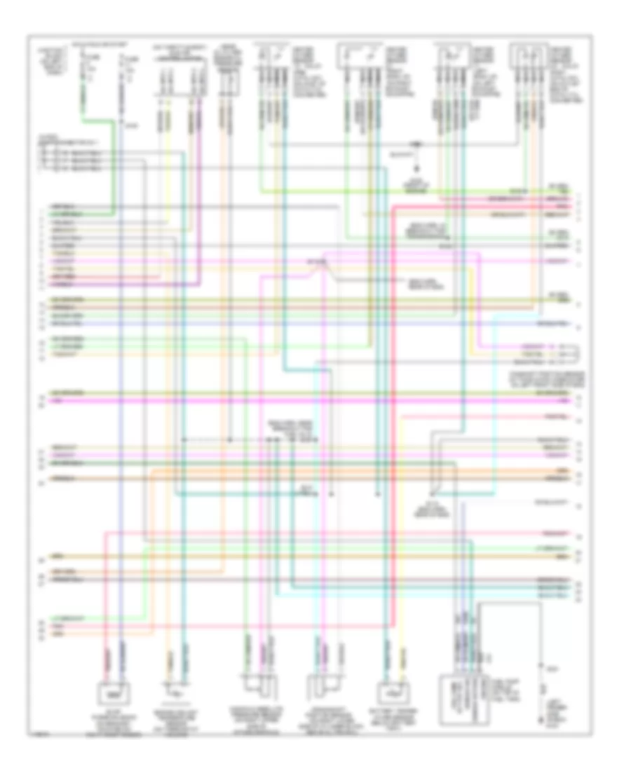
8.0L
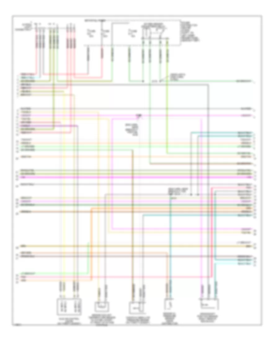
8.0L, Engine Performance Wiring Diagrams (1 of 3) for Dodge Cab & Chassis R2002 3500
List of elements for 8.0L, Engine Performance Wiring Diagrams (1 of 3) for Dodge Cab & Chassis R2002 3500:
- (calif)
- (eng harn, near break- out for fuel inj 1)
- (eng harn, rear of eng)
- (front of
- (in pdc) joint connector no2
- A14
- Automatic shutdown relay
- Cam pos sns
- Capacitor
- Controller anti-lock brake (4wabs: in eng compt, mounted on hydraulic control unit; rwabs: in eng compt, on left front inner fender panel)
- Crnk pos sns
- Ect sens in
- Engine)
- F18
- Fuel injectors
- Fuel pump relay
- Fuse 20a
- Fuse 30a
- Fused b(+)
- G105
- G60
- Gen field drv
- Gov press sig
- Ground
- Ho2s 1/1 sig
- Ho2s 1/2 sig
- Ho2s 1/3 sig
- Ho2s 2/1 sig
- Hot at all times
- Iat sens in
- Idle air 1
- Idle air 2
- Idle air 3
- Idle air 4
- Ign coil dvr 1
- Ign coil dvr 2
- Ign coil dvr 3
- Ign coil dvr 4
- Ign coil dvr 5
- Ign power
- Ignition coil 4-pack
- Ignition coil 6-pack
- Inj 1 driver
- Inj 10 driver
- Inj 2 driver
- Inj 3 driver
- Inj 4 driver
- Inj 5 driver
- Inj 6 driver
- Inj 7 driver
- Inj 8 driver
- Inj 9 driver
- K11
- K115
- K116
- K12
- K13
- K14
- K141
- K17
- K18
- K19
- K20
- K21
- K22
- K24
- K241
- K26
- K28
- K30
- K32
- K341
- K38
- K39
- K40
- K41
- K43
- K44
- K54
- K58
- K59
- K60
- K88
- Map sens in
- Nca
- Oil press sig
- Output sens
- Output speed sensor (on left side of transmission)
- Overdrv sol
- Park/neutral position switch (on left side of transmission)
- Pnk
- Power distribution center (in eng compt, on left inner fender panel, near battery)
- Powertrain control module (in eng compt, on right side of firewall)
- Prk/neutral
- S107
- S117
- S123
- S126
- S127 (eng harn, at transmission)
- S131
- Sensor grd
- Starting/ charging system
- T13
- T14
- T25
- T41
- T54
- T60
- Tan
- Tcc drvr
- To spark plugs
- Tps sens in
- Trans relay
- Trans temp in
- Var frce sol
- Vss in
- Z12
8.0L, Engine Performance Wiring Diagrams (2 of 3) for Dodge Cab & Chassis R2002 3500
List of elements for 8.0L, Engine Performance Wiring Diagrams (2 of 3) for Dodge Cab & Chassis R2002 3500:
- (calif)
- (eng harn, in breakout for transmission)
- (eng harn, near breakout for fuel inj 5) s121
- (eng harn, rear of eng)
- (in pdc) joint connector no 1
- (left fender side shield)
- (near oil filter) engine oil pressure sensor
- (on right lower side of cylinder block, above oil pan rail)
- (on throttle body) idle air control motor
- (pre- catalyst) (on inlet of catalytic converter)
- A61
- Battery temper- ature sensor (below battery tray)
- Camshaft position sensor (in timing chain case/cover on left front side of eng)
- Crankshaft position sensor
- Engine coolant temperature sensor (on thermostat housing)
- Evap purge solenoid (on bracket, mounted on right inner fender)
- Fuel pump
- Fuel pump module (on top of fuel tank)
- Fuse 10a
- G100
- G105 (front of engine)
- Ground
- Heated oxygen sensor 1/1 (left bank up) (on left exhaust downpipe)
- Heated oxygen sensor 1/2
- Heated oxygen sensor 2/1 (right bank up) (on right exhaust downpipe)
- Heated oxygen sensor 2/2 (post- catalyst) (on outlet end of catalytic converter)
- Hot in run or start
- Iac mtr 1
- Iac mtr 2
- Iac mtr 3
- Iac mtr 4
- Junction block (on left end of dash)
- K226
- Manifold absolute pressure sensor (on right upper side of intake manifold)
- Nca
- Pnk
- S105
- S118 (eng harn, rear of eng)
- S119
- S122
- S124
- S130
- S331
- Sensor return
- Sensor sig rly out (b+)
- Z13
8.0L, Engine Performance Wiring Diagrams (3 of 3) for Dodge Cab & Chassis R2002 3500
List of elements for 8.0L, Engine Performance Wiring Diagrams (3 of 3) for Dodge Cab & Chassis R2002 3500:
- (headlamp & dash harn, in pdc)
- (headlamp & dash harn, rear of front bumper)
- (m/t only)
- A/c comp rly
- A/c request
- A/c select in
- A142
- Air condi- tioning system
- Air conditioning system
- Asd relay sens
- Auto sht rly
- Batt temp sens
- Brake sw in
- C13
- C20
- C90
- Ccd (+)
- Ccd (-)
- Ccd bus (+)
- Ccd bus (-)
- Cruise control system
- Cruise feed
- Cruise sw in
- Cruise vac sol
- Cruise vnt sol
- D20
- D21
- Data link connector (left bottom of dash)
- Downstream oxygen sensor relay
- Evap sol drvr
- Fuel pmp rly
- Fuse i 20a
- Fuse k 15a
- G200 (left kick panel)
- Gen field out
- Generator
- Gov press sig
- Ho2s 1/1 htr ctrl
- Ho2s 2/1 htr ctrl
- Ho2s dn rly ctrl
- Hot at all times
- Instrument cluster
- Intake air temperature sensor (in left front side of intake manifold)
- Joint connector 1 (in pdc)
- Joint connector no7 (left side of instrument panel)
- K106
- K107
- K118
- K125
- K145
- K199
- K226
- K299
- K31
- K51
- K52
- K54
- K88
- Leak detec pmp
- Leak detection pump (on right front of inner fender)
- Low fuel sens
- Overdrive switch
- Overdrv sol
- Pnk
- Power distribution center (in eng compt, on left inner fender panel, near battery)
- Powertrain control module (in eng compt, on right side of firewall)
- Red
- S116 (eng harn, rear of eng)
- S176
- S180
- Sci receive
- Sci transmit
- Sensor grd
- Stop lamp switch (on brake pedal bracket)
- T16
- T25
- T54
- T60
- Tan/red
- Tcc sol ctrl
- Throttle position sensor (on throttle body)
- Trans overdrive
- Trans rly out
- Trans temp sns
- Transmission relay
- Transmission solenoid assembly (on left side of transmission)
- V32
- V35
- V36
- V37
- V40
- Var force sol
EXTERIOR LIGHTS
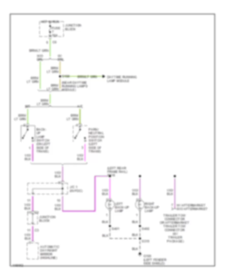
Back-up Lamps Wiring Diagram for Dodge Cab & Chassis R2002 3500
List of elements for Back-up Lamps Wiring Diagram for Dodge Cab & Chassis R2002 3500:
- (left rear frame rail) s316
- (near daytime running lamps module)
- (w/ trailer package)
- A/t
- Automatic day/night mirror (highline)
- Back- up lamp switch (on left side of trans)
- Daytime running lamp module
- Fuse 10a
- G100 (left fender side shield)
- Hot in run
- J/c 1 (in pdc)
- Junction block
- Left back-up lamp
- M/t
- Park/ neutral position switch (left side of trans)
- Right back-up lamp
- S108
- S315
- S401
- S402
- Trailer tow connector or aftermarket trailer tow connector
- W/ aftermarket w/o aftermarket
- W/ drl
- W/o drl
Exterior Lamps & Trailer connector Wiring Diagram (1 of 2) for Dodge Cab & Chassis R2002 3500
List of elements for Exterior Lamps & Trailer connector Wiring Diagram (1 of 2) for Dodge Cab & Chassis R2002 3500:
- (left fender side shield) g100
- (left frame rail)
- (left frame rail) s313
- (left front fender area) s104
- (left s314
- (near left front park/ turn signal lamp)
- (near right front park/ turn signal lamp)
- (right of radiator) s141
- Center high mounted stop lamp 1
- Center high mounted stop lamp 2
- Combination flasher
- Frame rail)
- Fuse 10 10a
- Fuse 4 20a
- Fuse 5 20a
- Fuse f 20a
- G100 (left fender side shield)
- G201 (right dash center support)
- G301 (below left rear speaker)
- Hazard
- Head
- Headlamp switch
- Hot at all times
- Hot in acc or run
- Instrument cluster
- J/c 6 (left side of dash)
- Junction block
- Left
- Left front park/turn signal lamp
- Left license lamp
- Left tail/ stop/turn signal lamp
- Left turn ind
- Normal
- Off
- Park
- Pnk
- Pnk/red
- Power distribution center
- Right
- Right front park/turn signal lamp
- Right license lamp
- Right tail/ stop/turn signal lamp
- Right turn ind
- S102
- S103
- S150
- S151
- S311
- S315
- S317
- S401
- S402
- Stop lamp switch (on brake pedal bracket)
- Tan
- Timing control
- Turn signal/ hazard switch (part of multi- function switch)
- W/ dual rear wheels
- W/ trailer tow
- W/o dual rear wheels
- W/o trailer tow
Exterior Lamps & Trailer connector Wiring Diagram (2 of 2) for Dodge Cab & Chassis R2002 3500
List of elements for Exterior Lamps & Trailer connector Wiring Diagram (2 of 2) for Dodge Cab & Chassis R2002 3500:
- (w/ aftermarket)
- (w/o aftermarket)
- Aftermarket center high mounted stop lamp
- Back-up lamps circuit
- Battery (+)
- Brake (+)
- Center identification lamp
- Electric brake (highline)
- Fuse 8 40a
- G100 (left fender side shield)
- G102 (left fender side shield)
- G201 (right center dash support)
- G302 (at overhead console)
- Ground
- Hot at all times
- J/c 1 (in power distribution center)
- J/c 2 (in power distribution center)
- Left front fender lamp
- Left license lamp
- Left outboard clearance lamp
- Left outboard identification lamp
- Left rear fender lamp
- Power distribution center
- Rear wheels
- Right front fender lamp
- Right outboard clearance lamp
- Right outboard identification lamp
- Right rear fender lamp
- Right tailgate lamp
- S114 (in breakout to chassis harness)
- S315
- S318 (w/o aftermarket trailer tow)
- S319 (w/o aftermarket trailer tow)
- S320 (w/o aftermarket trailer tow) (in trailer tow breakout)
- S321
- S322 (at roof lamps)
- S325
- S404
- S406 (near breakout to tailgate lamp)
- Stoplight sw
- Trailer tow connector or aftermarket trailer tow connector (if equipped)
- Trailer tow relay (w/ trailer package) (in power distribution center)
- W/ dual
- W/ highline only
- W/0 aftermarket trailer tow
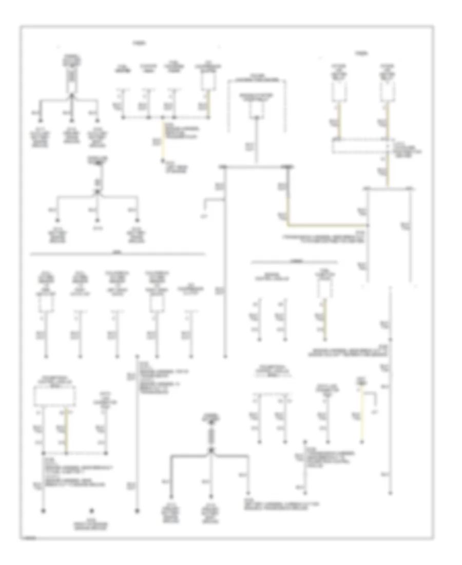
GROUND DISTRIBUTION
Ground Distribution Wiring Diagram (1 of 4) for Dodge Cab & Chassis R2002 3500
List of elements for Ground Distribution Wiring Diagram (1 of 4) for Dodge Cab & Chassis R2002 3500:
- (8.0l) oxygen sensor 1/2 pre- catalyst
- (8.0l) oxygen sensor 1/3 post catalyst
- (california) oxygen sensor 1/2 left bank down
- (california) oxygen sensor 2/2 right bank down
- (diesel) auxiliary battery
- (diesel) battery
- (gasoline) battery
- (not used)
- A/c compressor clutch
- A/t
- Cummins bus
- Data link connector (dlc)
- Diesel
- Engine control module
- Engine starter motor relay
- Fuel heater
- Fuel injection pump
- Fuel transfer pump
- G105 (front of engine) (engine ground)
- G107 (left rear of engine)
- G113 (primary battery engine ground)
- G114 (battery engine ground)
- G115
- G115 (primary battery body ground)
- G116 (battery frame ground)
- G117 (auxiliary battery engine ground)
- G118 (primary frame ground)
- G120 (auxiliary battery body ground)
- Gas
- Intake air heater relay
- J/c 2 (in power distribution center)
- M/t
- Power distribution center
- Powertrain control module (pcm)
- S109 (battery harness, in break out for engine & transmission ground)
- S122 (8 cyl) (engine harness, top of transmission) (10 cyl) (engine harness, in break out to transmission)
- S126 (8 cyl) (engine harness, near breakout to fuel injector 1) (10 cyl) (engine harness, near break out to engine ground)
- S128 (transmission harness, near break out to power distribution center)
- S164 (engine harness, near fuel transfer pump)
- S168 (engine harness, near break out to engine coolant temperature sensor)
- Z12
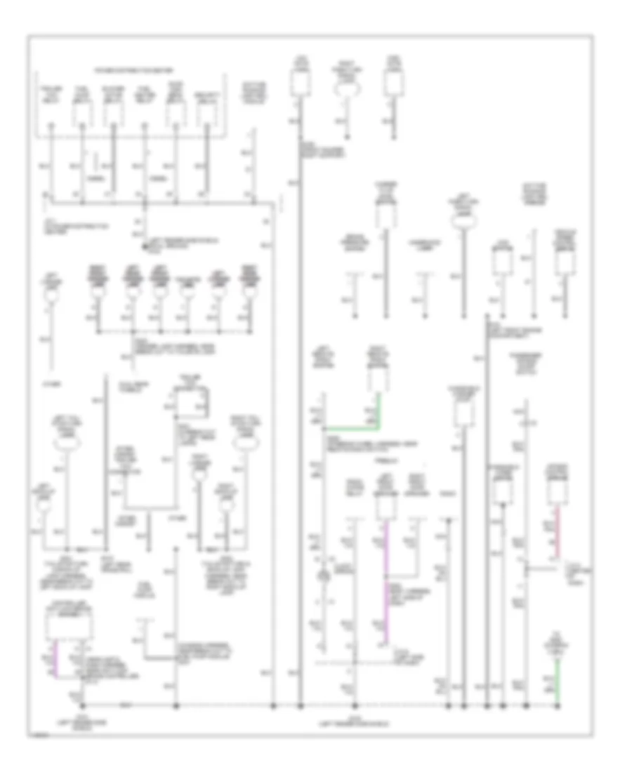
Ground Distribution Wiring Diagram (2 of 4) for Dodge Cab & Chassis R2002 3500
List of elements for Ground Distribution Wiring Diagram (2 of 4) for Dodge Cab & Chassis R2002 3500:
- (chassis harness, near break out to fuel pump module) s331
- (left fender side shield) (rwal ground) g102
- 4wd switch
- After- market
- After- market trailer tow connector
- Air bag control module
- Blower motor relay
- Brake controller) s112
- Brake pressure switch
- Clock spring
- Controller anti-lock brake (4wabs)
- Daytime running lamp (drl) module
- Diesel
- Dual rear wheels
- Fuel heater relay
- Fuel pump module
- Fuel pump relay
- G100 (left fender side shield)
- G101 (left fender side shield)
- High note horn
- J/c 1 (in power distribution center)
- J/c 6 (left side of dash)
- J/c 8 (center of dash)
- Left back-up lamp
- Left front door speaker
- Left left front front fender fender lamp lamp
- Left left license license lamp lamp
- Left left rear rear fender fender lamp lamp
- Left license lamp
- Left park/turn signal lamp
- Left remote radio switch
- Left tail/ stop/turn signal lamp
- Low note horn
- Nca
- Other
- Passenger air bag on/off switch
- Power distribution center
- Premium
- Quad high beam relay
- Radio
- Radio choke relay
- Right back-up lamp
- Right front door speaker
- Right license lamp
- Right park/turn signal lamp
- Right remote radio switch
- Right right front front fender fender lamp lamp
- Right right rear rear fender fender lamp lamp
- Right tail/ stop/turn signal lamp
- S150 (front bumper right support)
- S151 (left front engine compartment)
- S209 (steering wheel harness, near remote radio switch)
- S302 (body harness, left side of dash)
- S315 (left rear frame rail)
- S321 (in break out to left rear lamps)
- S401 (tail/stop/turn & back-up lamp harness, near break out to left back-up lamp)
- S402 (tail/stop/turn & back-up lamp harness, near break out to right back-up lamp)
- S404 (fender lamp harness, near break out to tailgate lamp)
- Security relay
- Tailgate tailgate lamp lamp
- To g200 (diagram 3 of 4)
- Trailer tow connector
- Trailer tow relay
- Underhood lamp
- Vehicle speed control servo
- Washer fluid level switch
- Windshield washer pump
- Windshield wiper motor
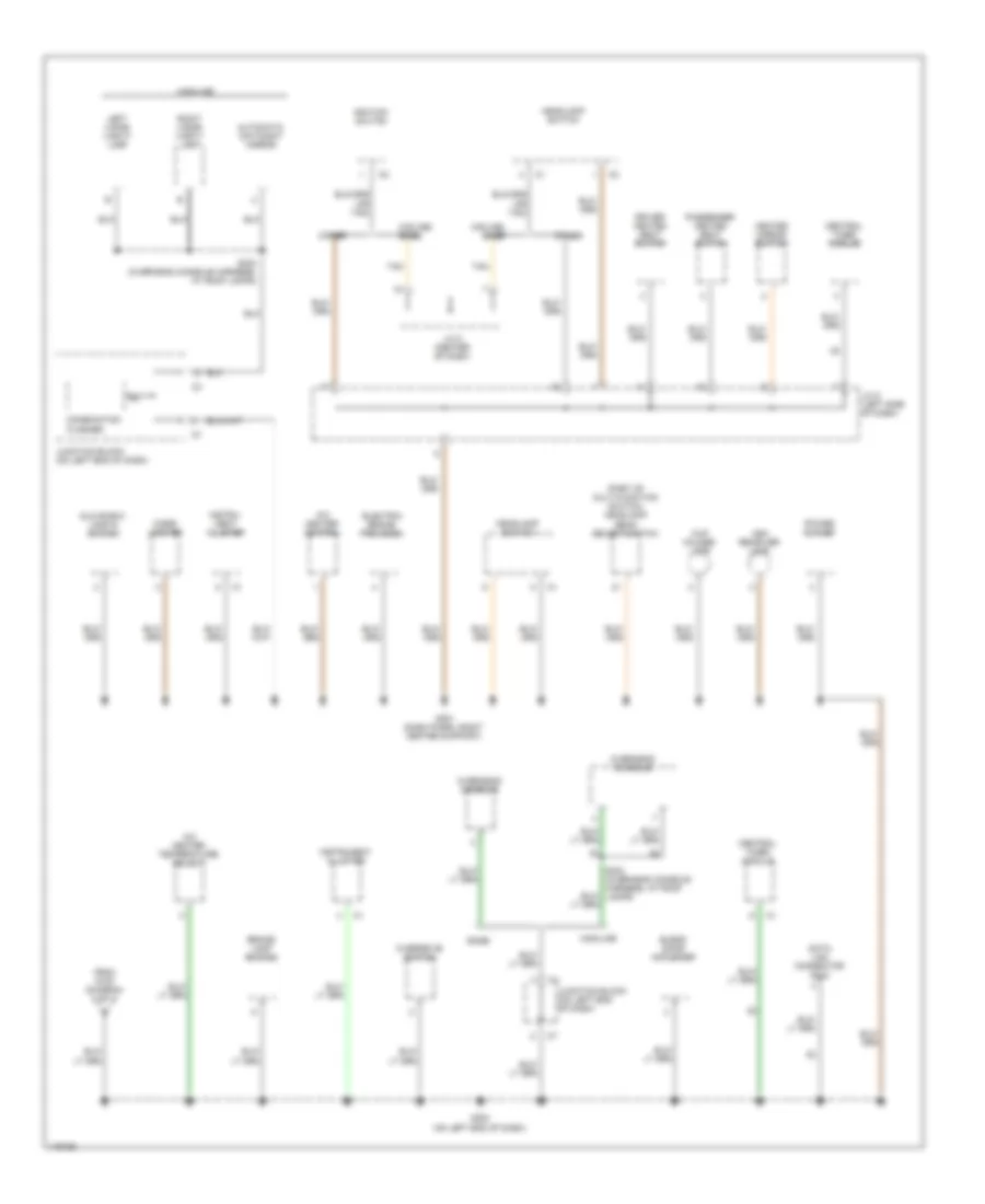
Ground Distribution Wiring Diagram (3 of 4) for Dodge Cab & Chassis R2002 3500
List of elements for Ground Distribution Wiring Diagram (3 of 4) for Dodge Cab & Chassis R2002 3500:
- (part of multi-function switch) headlamp beam select switch
- A/c heater control
- A/c heater temperature select
- Ash receiver lamp
- Automatic day/night mirror
- Base
- Blend door actuator
- Brake lamp switch
- Central timer module
- Cigar lighter
- Combination flasher
- Cup holder lamp
- Data link connector (dlc)
- Driver heated seat switch
- Electric brake provision
- From g100 (diagram 2 of 4)
- G200 (on left end of dash)
- G201 (dash panel right center support)
- Glove box lamp & switch
- Headlamp switch
- Heated mirror switch
- Highline
- Ignition switch
- Instru- ment cluster
- Instrument cluster
- J/c 5 (left side of dash)
- J/c 8 (center of dash)
- Junction block (on left end of dash)
- Left visor/ vanity lamp
- Midline/ base
- Other
- Overdrive switch
- Overhead console
- Passenger heated seat switch
- Power outlet
- Right visor/ vanity lamp
- S323 (overhead console harness, at roof lamps)
- S340 (overhead console harness, at roof lamps)
- Tan
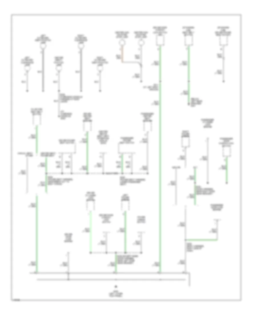
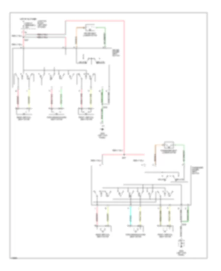
Ground Distribution Wiring Diagram (4 of 4) for Dodge Cab & Chassis R2002 3500
List of elements for Ground Distribution Wiring Diagram (4 of 4) for Dodge Cab & Chassis R2002 3500:
- (at overhead console) g302
- (below left rear speaker) g301
- (club cab) seat belt switch
- (heated seats) seat heat interface module (shim)
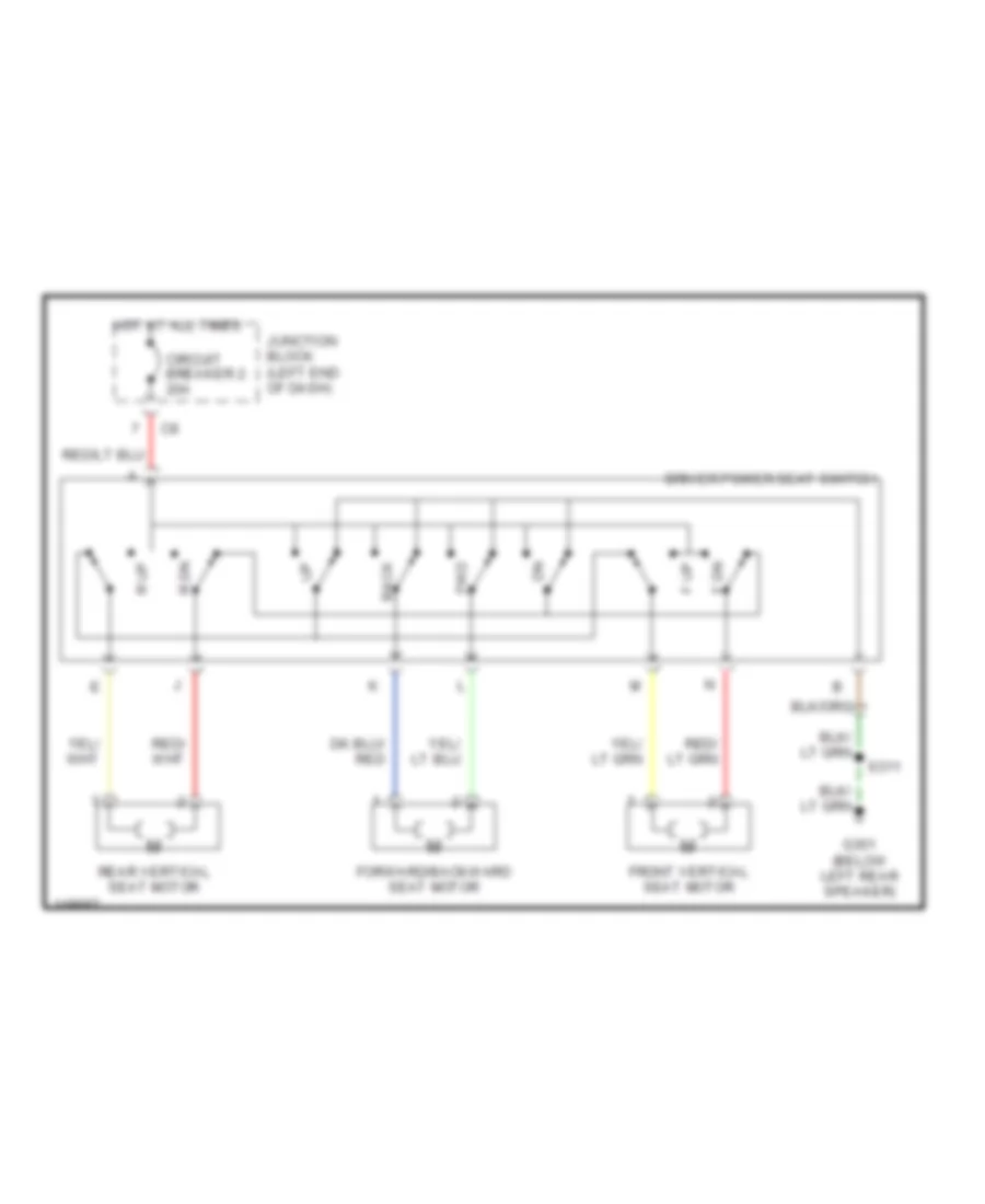
- (standard cab) driver power seat switch
- (standard cab) seat belt switch
- Center high mounted stop lamp
- Center identi- fication lamp
- Driver cylinder lock switch
- Driver door ajar switch
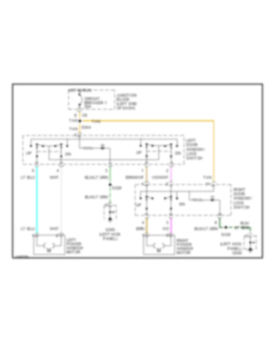
- Driver door window/ lock switch
- Driver door window/ lock switch (iem)
- Driver heated seat cushion
- Driver power seat switch
- G300 (left lower kick panel)
- Heated seat/ power seat
- Left outboard clearance lamp
- Left outboard identification lamp
- Left power mirror
- Manual seat/ other
- Midline
- Passenger cylinder lock switch
- Passenger door ajar switch
- Passenger door window/lock switch
- Passenger heated seat cushion
- Passenger power seat switch
- Power mirror switch
- Right outboard clearance lamp
- Right outboard identification lamp
- Right power mirror
- S305 (body harness, right side of dash)
- S311 (at left body ground)
- S325 (overhead console harness at roof lamps)
- S328 (power seat harness, near break out to body wiring)
- S329 (except base) (door harness, near left door near grommet)
- S336 (power seat harness, under passenger seat)
- Slt
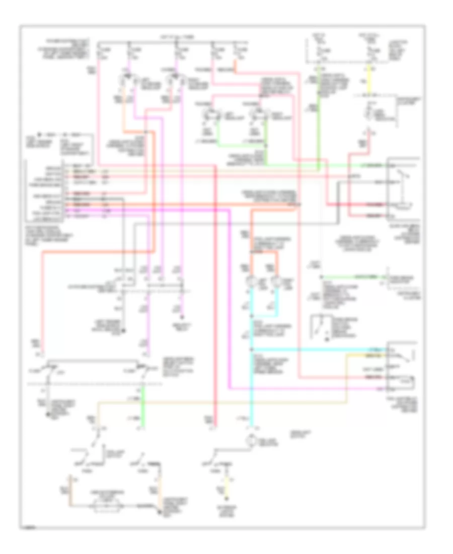
HEADLIGHTS
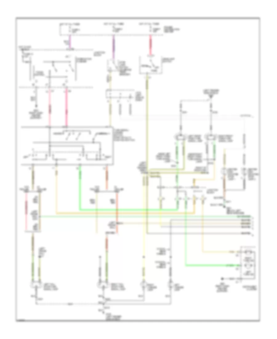
Headlight Wiring Diagram, with DRL & with Quad Headlights for Dodge Cab & Chassis R2002 3500
List of elements for Headlight Wiring Diagram, with DRL & with Quad Headlights for Dodge Cab & Chassis R2002 3500:
- (above steering column) j/c 5
- (fog lamp harness, in breakout to right fog lamp) s136
- (headlamp & dash harness, in breakout to daytime running lamps module)
- (headlamp & dash harness, near breakout to power distribution center) s143
- (headlamp & dash harness, near intake air heater relay) s181
- (instrument panel right center support) g201
- (left fender side shield) (rwal ground) g102
- (not used)
- 87a
- Daytime running lamp (drl) module (in engine compartment, on left inner fender panel)
- Exterior lights system
- Flash
- Fog lamp ctrl
- Fog lamp indicator
- Fog lamp relay (on power distribution center)
- Fog lamp switch
- Fuse 10a
- Fuse b 15a
- Fuse c 15a
- Fuse e 15a
- Fuse f 20a
- Fuse g 15a
- Fused b (+)
- G100 (left fender side shield)
- G11
- G34
- Ground
- Head
- Headlamp beam select switch (part of multi-function switch)
- Headlight switch
- High
- High beam ind
- High beam indicator
- High beam out
- High low
- Hot at all times
- Hot in run
- Ignition
- Instrument cluster
- J/c 1 (in power distribution center)
- Junction block (on left end of dash)
- L10
- L139
- L34
- Left fog lamp
- Left headlamp
- Left outboard headlamp
- Low
- Low beam out
- Off
- Park
- Park brake indicator
- Park brake sen
- Park brake switch (on park brake mechanism)
- Pnk/ red
- Pnk/red
- Power distribution center (in engine compartment, on left inner fender panel, near battery)
- Quad high beam relay (in power distribution center)
- Right fog lamp
- Right headlamp
- Right outboard headlamp
- S106 (headlamp & dash harness, in power distribution center)
- S110 (headlamp & dash harness, near left wheel speed sensor)
- S134 (fog lamp harness, in breakout to right fog lamp)
- S144 (headlamp & dash harness, near breakout to j/c 3)
- S151 (left front of engine compartment)
- S177 (headlamp & dash harness, in breakout to daytime running lamps (drl) module)
- S182
- Security relay
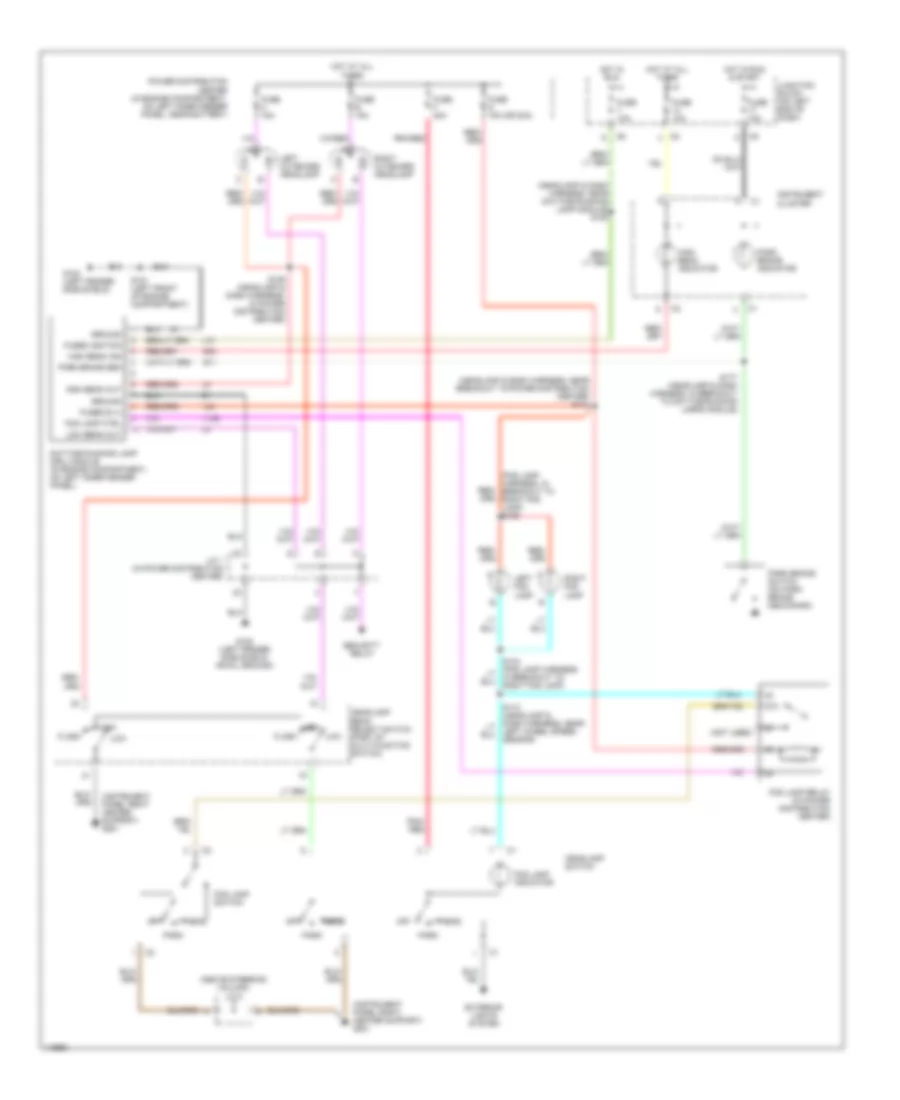
Headlight Wiring Diagram, with DRL & without Quad Headlights for Dodge Cab & Chassis R2002 3500
List of elements for Headlight Wiring Diagram, with DRL & without Quad Headlights for Dodge Cab & Chassis R2002 3500:
- (above steering column) j/c 5
- (fog lamp harness, in breakout to right fog lamp) s136
- (headlamp & dash harness, near breakout to power distribution center) s143
- (headlamp & dash harness, near daytime running lamp module) s108
- (instrument panel right center support) g201
- (not used)
- 87a
- Daytime running lamp (drl) module (in engine compartment, on left inner fender panel)
- Exterior lights system
- Flash
- Fog lamp ctrl
- Fog lamp indicator
- Fog lamp relay (in power distribution center)
- Fog lamp switch
- Fuse 10a
- Fuse b 15a
- Fuse c 15a
- Fuse f 20a
- Fuse g 15a (or 20a)
- Fused b (+)
- Fused ignition
- G100 (left fender side shield)
- G102 (left fender side shield) (rwal ground)
- G11
- G34
- Ground
- Head
- Headlamp beam select switch (part of multi-function switch)
- Headlamp switch
- High
- High beam ind
- High beam indicator
- High beam out
- Hot at all times
- Hot in run
- Hot in run & start
- Instrument cluster
- J/c 1 (in power distribution center)
- Junction block (on left end of dash)
- L10
- L139
- L34
- Left fog lamp
- Left outboard headlamp
- Low
- Low beam out
- Off
- Park
- Park brake indicator
- Park brake sen
- Park brake switch (on park brake mechanism)
- Pnk/ red
- Pnk/red
- Power distribution center (in engine compartment, on left inner fender panel, near battery)
- Right fog lamp
- Right outboard headlamp
- S106 (headlamp & dash harness, in power distribution center)
- S110 (headlamp & dash harness, near left wheel speed sensor)
- S134 (fog lamp harness, in breakout to right fog lamp)
- S151 (left front of engine compartment)
- S177 (headlamp & dash harness, in breakout to daytime running lamps module)
- Security relay
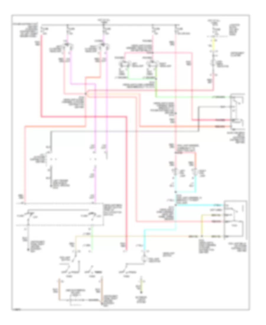
Headlight Wiring Diagram, without DRL & with Quad Headlights for Dodge Cab & Chassis R2002 3500
List of elements for Headlight Wiring Diagram, without DRL & with Quad Headlights for Dodge Cab & Chassis R2002 3500:
- (above steering column) j/c 5
- (fog lamp harness, in breakout to right fog light) s136
- (headlamp & dash harness, near breakout to power distribution center) s143
- (headlamp & dash harness, near intake air heater relay) s181
- (instrument panel right center support) g201
- (left fender side shield) (rwal ground) g102
- (not used)
- 87a
- Exterior lights system
- Flash
- Fog lamp indicator
- Fog lamp relay (on power distribution center)
- Fog lamp switch
- Fog lamp)
- Fuse 10a
- Fuse b 15a
- Fuse c 15a
- Fuse e 15a
- Fuse f 20a
- Fuse g 15a (or 20a)
- Head
- Headlamp beam select switch (part of multi-function switch)
- Headlamp switch
- High
- High beam indicator
- Hot at all times
- Instrument cluster
- J/c 1 (in power distribution center)
- Junction block (on left end of dash)
- Left fog lamp
- Left headlamp
- Left outboard headlamp c
- Low
- Off
- Park
- Pnk/ red
- Pnk/red
- Power distribution center (in engine compartment, on left inner fender panel)
- Quad high beam relay (on power distribution center)
- Right fog lamp
- Right headlamp
- Right outboard headlamp c
- S106 (headlamp & dash harness, in power distribution center)
- S110 (headlamp & dash harness, near left wheel speed sensor)
- S144 (headlamp & dash harness, near breakout to j/c 3)
- S183 (headlamp & dash harness, in power distribution center)
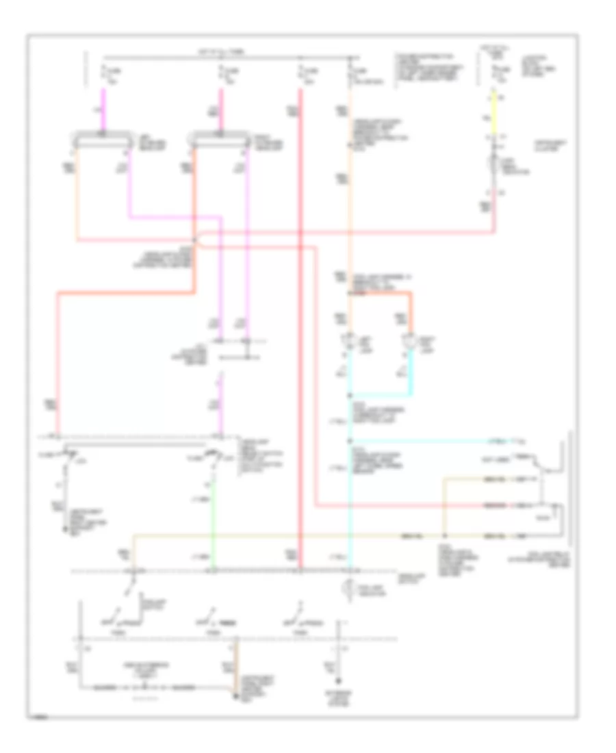
Headlight Wiring Diagram, without DRL & without Quad Headlights for Dodge Cab & Chassis R2002 3500
List of elements for Headlight Wiring Diagram, without DRL & without Quad Headlights for Dodge Cab & Chassis R2002 3500:
- (above steering column) j/c 5
- (fog lamp harness, in breakout to right fog lamp) s136
- (headlamp & dash harness, near breakout to power distribution center) s143
- (instrument panel right center support) g201
- (not used)
- 87a
- Exterior lights system
- Flash
- Fog lamp indicator
- Fog lamp relay (in power distribution center)
- Foglamp switch
- Fuse 10a
- Fuse b 15a
- Fuse c 15a
- Fuse f 20a
- Fuse g 15a (or 20a)
- Head
- Headlamp beam select switch (part of multi-function switch)
- Headlamp switch
- High
- High beam indicator
- Hot at all times
- Instrument cluster
- J/c 1 (in power distribution center)
- Junction block (on left end of dash)
- Left fog lamp
- Left outboard headlamp
- Low
- Off
- Park
- Pnk/ red
- Power distribution center (in engine compartment, on left inner fender panel, near battery)
- Right fog lamp
- Right outboard headlamp
- S106 (headlamp & dash harness, in power distribution center)
- S110 (headlamp & dash harness, near left wheel speed sensor)
- S134 (fog lamp harness, in breakout to right fog lamp)
- S183 (headlamp & dash harness, in power distribution center)
HORN
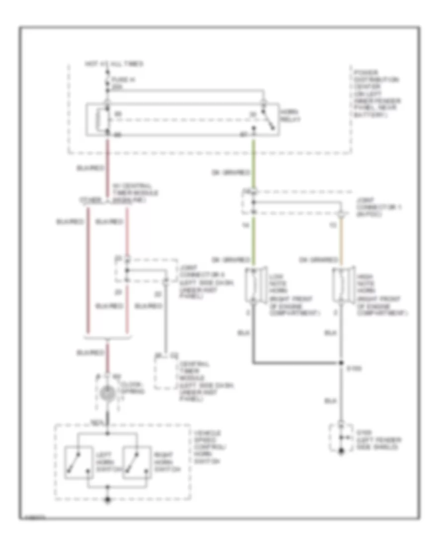
Horn Wiring Diagram for Dodge Cab & Chassis R2002 3500
List of elements for Horn Wiring Diagram for Dodge Cab & Chassis R2002 3500:
- (left side dash, under inst panel)
- (right front of engine compartment)
- Central timer module (left side dash, under inst panel)
- Clock- spring
- Fuse h 20a
- G100 (left fender side shield)
- High note horn
- Horn relay
- Hot at all times
- Joint connector 1 (in pdc)
- Joint connector 6
- Left horn switch
- Low note horn
- Nca
- Other
- Power distribution center (on left inner fender panel, near battery)
- Right horn switch
- S150
- Vehicle speed control/ horn switch
- W/ central timer module (highline)
INSTRUMENT CLUSTER
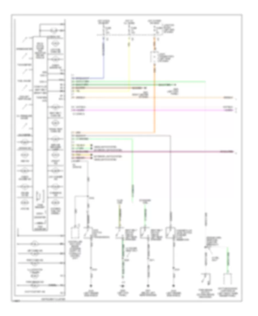
Instrument Cluster Wiring Diagram (1 of 2) for Dodge Cab & Chassis R2002 3500
List of elements for Instrument Cluster Wiring Diagram (1 of 2) for Dodge Cab & Chassis R2002 3500:
- (diesel)
- (engine harn, near fuel injector breakout) s117
- 025.6
- 4wd
- 4wd ind
- 4wd switch (on transmission)
- A10
- Abs ind
- Air bag ind
- B10
- Bright sen
- C1 (conn a)
- C2 (conn b)
- Ccd (+)
- Ccd (-)
- Check engine ind
- Check gauges ind
- Club cab
- Controller anti-lock brake (in engine compt, on hydraulic control unit)
- Coolant temp gauge
- Cruise on ind
- Daytime running lamp module (left front inner fender panel)
- Exterior lights system
- Fuel gauge
- Fuse 10a
- Fuse 5a
- G100 (left fender side shield)
- G200 (left kick panel)
- G201 (right center of dash)
- G300 (left kick panel)
- G301 (below left rear speaker)
- Gnd
- Headlights system
- Hi beam ind
- Hot at all times
- Hot in park or head
- Hot in run or start
- Illlumination (7 bulbs)
- Instrument cluster
- Joint connector 5 (left side of dash)
- Junction block (left end of dash)
- Left turn ind
- Low fuel warn ind
- Low washer ind
- Odometer
- Oil pressure gauge
- Overdrive ind
- Park brake ind
- Park brake switch (on park brake mechanism)
- Right turn ind
- S151
- S152
- S311
- S328
- Seat belt
- Seat belt switch (above left rear speaker)
- Seat belt warn ind
- Service reminder lamp
- Solid state gauge and indicator driver module
- Speedometer
- Standard cab
- Tachometer
- Tan
- Tone req
- Tone request
- Trans temp warn ind
- Trip odometer
- Upshift ind
- Voltmeter
- W/ drl only
- W/ power seat only
- Wait-to-start ind
- Wash fluid
- Washer fluid level switch (washer fluid reservoir)
- Water-in fuel ind
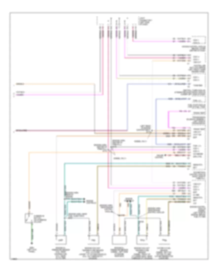
Instrument Cluster Wiring Diagram (2 of 2) for Dodge Cab & Chassis R2002 3500
List of elements for Instrument Cluster Wiring Diagram (2 of 2) for Dodge Cab & Chassis R2002 3500:
- (diesel only)
- (diesel)
- (engine harn, center of firewall) s172
- (engine harn, center of firewall) s173
- (engine harn, near engine control module)
- (engine harn, near fuel injector 5) s121
- (gas)
- (left rear of engine compartment) s174
- 5v ref
- Air bag control module (behind lower center of dash)
- Ccd (+)
- Ccd (-)
- Central timer module/ integrated electronic module (under left side of dash)
- Controller anti-lock brake (left front inner fender panel)
- Cruise control
- Ect
- Engine control module (diesel) (left side of engine, behind fuel filter)
- Engine controls
- Engine coolant temperature sensor (5.9l: in water jacket, at intake manifold) (8.0l: on thermostat housing)
- Engine coolant temperature sensor (diesel: front of cylinder head, near thermostat housing)
- Engine oil pressure sensor (5.9l: near distributor) (8.0l: near oil filter)
- Engine oil pressure sensor (diesel: left side of engine, near ecm)
- Eop
- Fuel lvl
- Fuel pump module (top of fuel tank)
- G13
- G200 (left kick panel)
- G60
- G85
- Joint connector 7 (left side of dash)
- K104
- K226
- O/d sense
- Overdrive switch (on steering column)
- Powertrain control module (right side of firewall)
- S118
- S165
- S166
- Sens rtn
- Spd ctrl
- T54
- Tone req
- Trans temp
- Transmission solenoid assembly (left side of transmission)
- V37
- Vss out
- Wait ind
- Water in fuel sensor (diesel: bottom of fuel filter/ water seperator canister)
- Wif
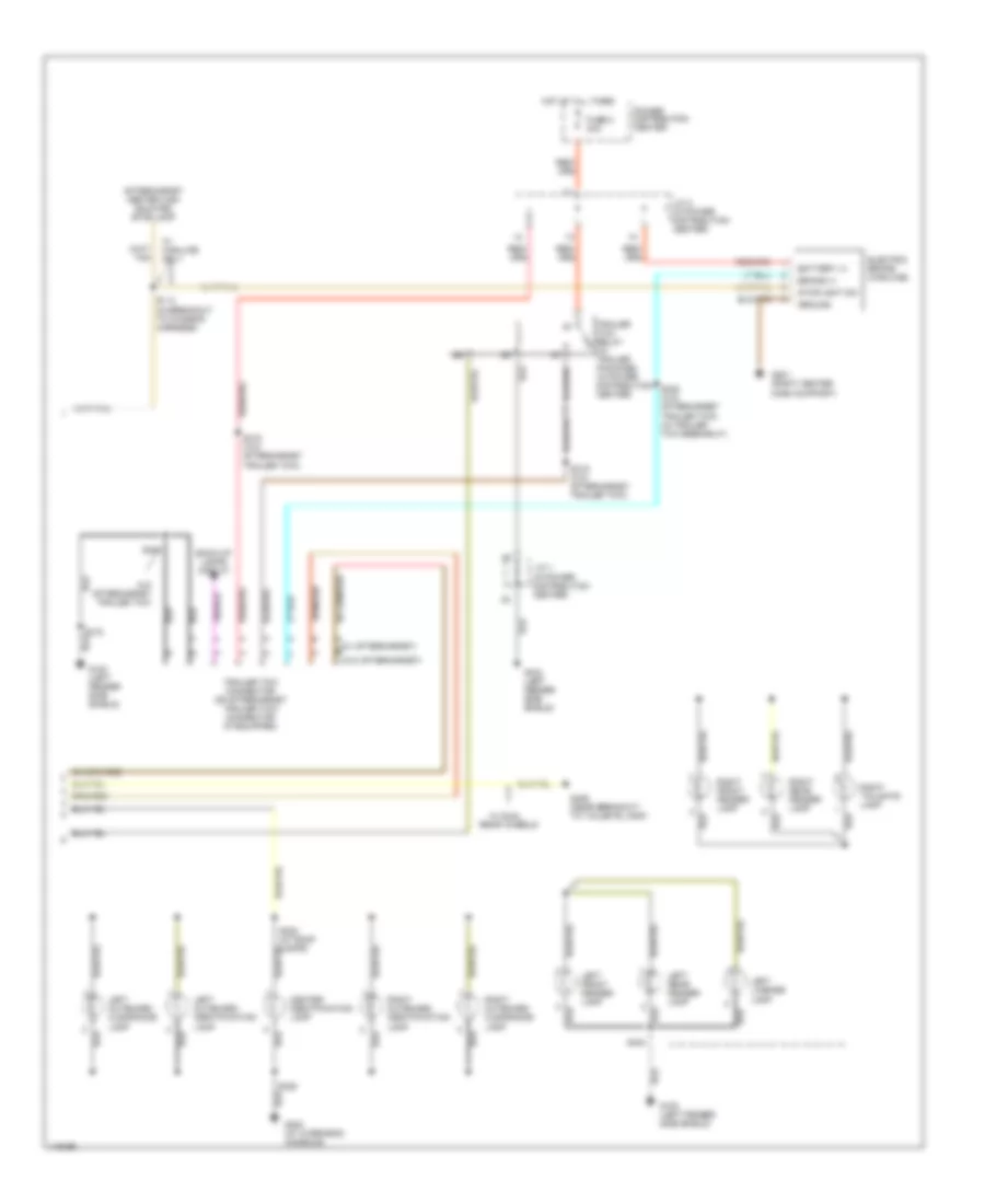
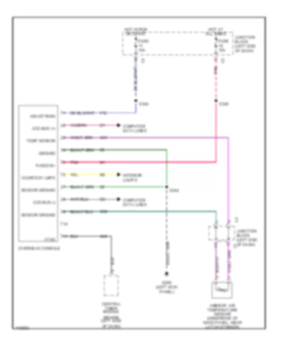
Overhead Console Wiring Diagram for Dodge Cab & Chassis R2002 3500
List of elements for Overhead Console Wiring Diagram for Dodge Cab & Chassis R2002 3500:
- (behind left side
- Ambient air temperature sensor (underside of hood panel, near latch striker)
- Ccd bus (+)
- Ccd bus (-)
- Central timer module
- Computer data lines
- Courtesy lmps
- F12
- Fuse 10a
- Fused b+
- G200 (left kick panel)
- G31
- G32
- G69
- Ground
- Hot at all times
- Hot in run or start
- Ign (st/run)
- Interior lights
- Junction block (left end of dash)
- Of dash)
- Overhead console
- Pnk
- S324
- S326
- S340
- Sensor ground
- Temp sensor
- Vtss
INTERIOR LIGHTS
Courtesy Lamps Wiring Diagram for Dodge Cab & Chassis R2002 3500
List of elements for Courtesy Lamps Wiring Diagram for Dodge Cab & Chassis R2002 3500:
- (at roof lamps) s323
- (at roof lamps) s326
- Base
- Cargo lamp 1
- Cargo lamp 2
- Central timer module (left side of dash)
- Data link connector (left bottom of dash)
- Dome lamp
- Driver door jamb switch
- Except base
- Fuse 10a
- G100 (left fender side shield)
- G200 (left end of dash)
- G201 (dash panel right center support)
- G300 (left lower kick panel)
- Glove box lamp & switch
- Headlamp switch
- High-line
- Highline
- Hot at all times
- Ignition switch
- Illumination parade dome cargo off park head
- J/c 5 (behind left side of dash)
- J/c 6 (near left kick panel)
- J/c 8 (near left kick panel)
- Junction block (left end of dash)
- Left visor/ vanity lamp
- Nca
- Overhead console
- Passenger door jamb switch
- Pnk
- Power mirrors switch
- Radio
- Right visor/ vanity lamp
- S151
- S305
- S310 (at left body ground)
- S332 (body harn, left side of dash)
- S340 (at roof lamps) (high-line only)
- Tan
- Underhood lamp
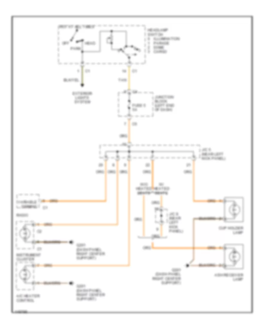
Instrument Illumination Wiring Diagram for Dodge Cab & Chassis R2002 3500
List of elements for Instrument Illumination Wiring Diagram for Dodge Cab & Chassis R2002 3500:
- A/c heater control
- Ash receiver lamp
- Cup holder lamp
- Exterior lights system
- Fuse 5 5a
- G201 (dash panel right center support)
- Head
- Headlamp switch
- Hot at all times
- Illumination parade dome cargo
- Instrument cluster
- J/c 5 (near left kick panel)
- J/c 8 (near left kick panel)
- Junction block (left end of dash)
- Off
- Park
- Radio
- Tan
- Variable dimming
- W/ heated seats
- W/o heated seats
POWER DISTRIBUTION
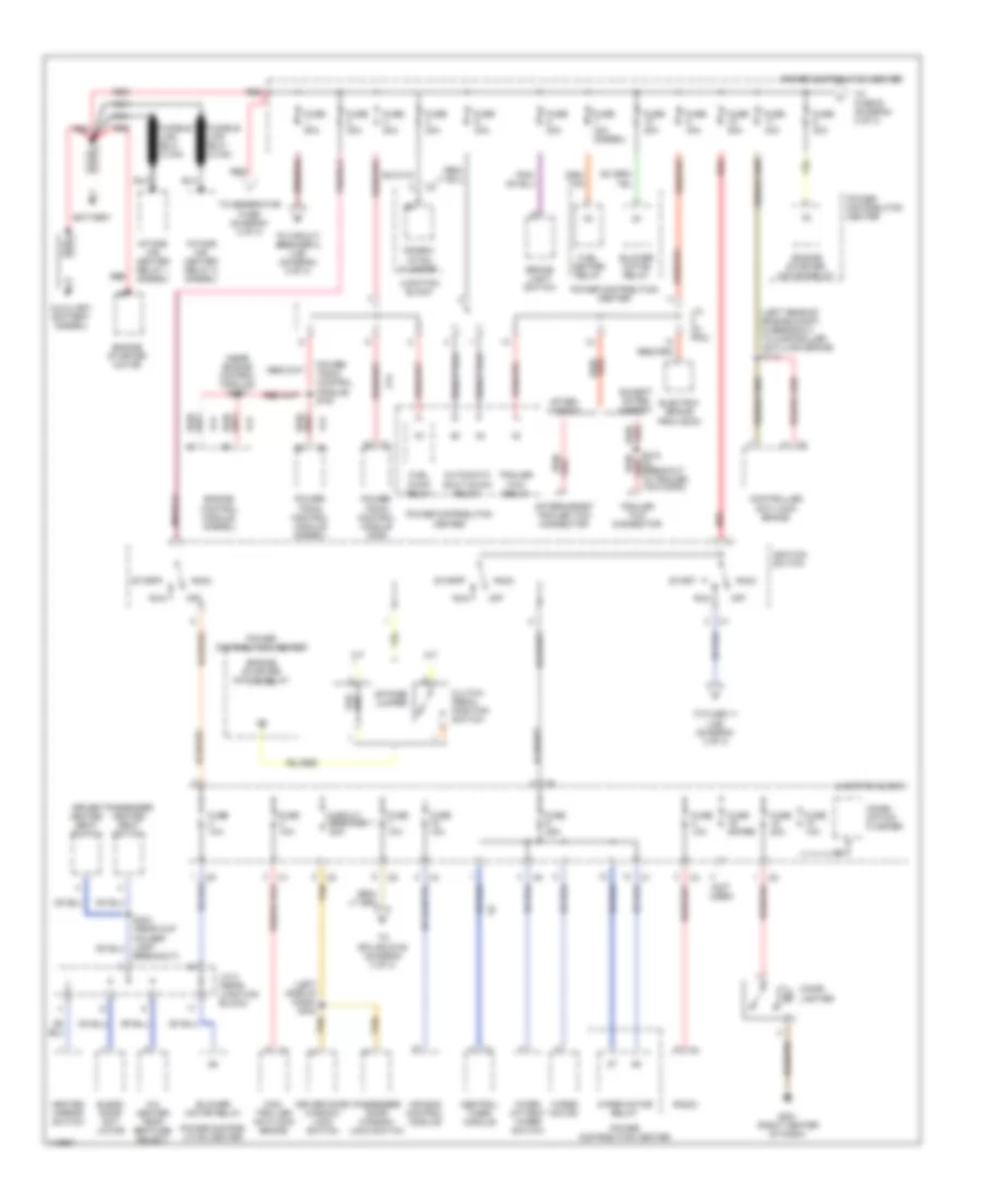
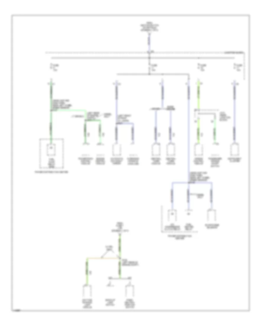
Power Distribution Wiring Diagram (1 of 3) for Dodge Cab & Chassis R2002 3500
List of elements for Power Distribution Wiring Diagram (1 of 3) for Dodge Cab & Chassis R2002 3500:
- (left rear of engine compt, in breakout to controller anti-lock brake) s113
- (left side of dash) s304
- (near engine control module) s167
- (not used)
- A/c heater temp- erature select
- A/t
- A14
- Acc
- After- market
- Aftermarket trailer tow connector
- Air bag control module
- Automatic shut down relay
- Auxiliary battery (diesel)
- Battery
- Blend door act- uator
- Blower motor relay
- Brake light switch
- Breakout)
- Bypass jumper
- Central timer module
- Cigar lighter
- Circuit breaker 1 20a
- Clutch pedal position switch
- Combi- nation flasher
- Combin- ation flasher
- Con- troller anti-lock brake
- Controller anti-lock brake
- Driver door window/ lock switch
- Driver heated seat switch
- Electric brake provision
- Engine starter motor relay
- Engine control module (diesel)
- Engine starter motor
- Engine starter motor relay
- Except after- market
- Fuel heater relay
- Fuel pump relay
- Fuse 10a
- Fuse 20a
- Fuse 25a
- Fuse 30a
- Fuse 40a
- Fuse 40a (diesel)
- Fuse 50a
- Fuse spare
- G201 (right center of dash)
- Heated mirror switch
- Ignition switch
- Intake air heater relay 1 (diesel)
- Intake air heater relay 2 (diesel)
- Inter- mittent wiper switch
- J/c (in pdc)
- J/c 8 (near junction block)
- Junction block
- M/t
- Nca
- Off
- Passenger door window/ lock switch
- Passenger heated seat switch
- Power distrib- ution center
- Power distribuiton center
- Power distribution center
- Power- train control module (diesel)
- Power- train control module (gas)
- Power- train control module) s161
- Radio
- Red
- Red/
- Run
- Start
- Tan
- To circuit breaker 2 (j/b) (diagram 2 of 3)
- To fuse 11 (j/b) (diagram 3 of 3)
- To fuse b (diagram 2 of 3)
- To generator fuse (diagram 2 of 3)
- To splice s108 (diagram 3 of 3)
- Trailer tow connector
- Trailer tow relay
- Wiper motor
- Wiper motor relay
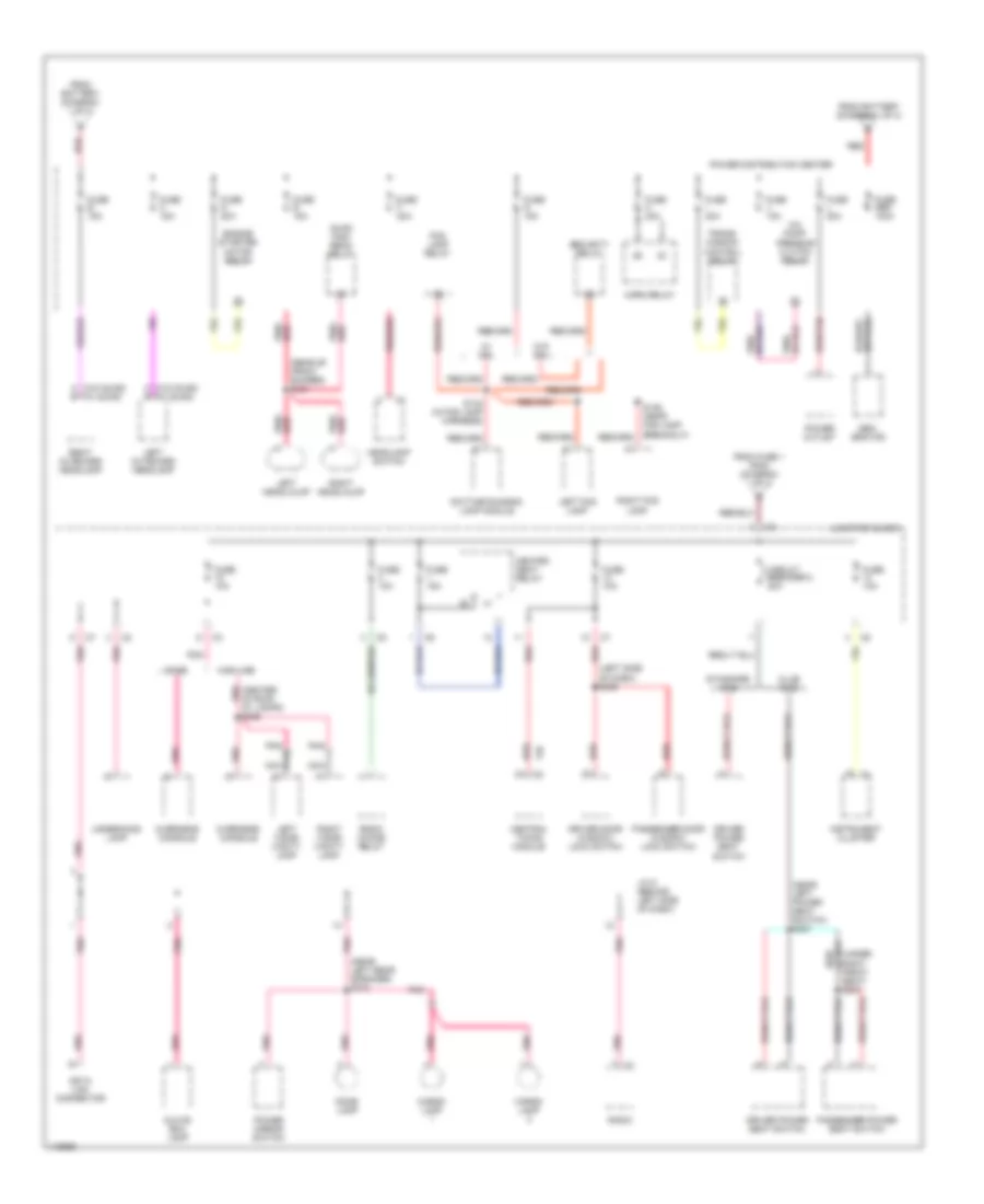
Power Distribution Wiring Diagram (2 of 3) for Dodge Cab & Chassis R2002 3500
List of elements for Power Distribution Wiring Diagram (2 of 3) for Dodge Cab & Chassis R2002 3500:
- (center of roof pnk at lamps) s326
- (left side of dash) s306
- (near left power seat switch) s327
- (near left rear speaker) s310
- (rear of front bumper) s181
- A (w/0 quad) (w/ quad)
- A/c comp- pressor clutch relay
- Base
- Cargo lamp
- Central timing module
- Circuit breaker 2 20a
- Club cab
- Data link connector
- Daytime running lamp module
- Dome lamp
- Driver door window/ lock switch
- Driver power seat switch
- Engine starter motor relay
- F35
- Fog lamp relay
- From battery (diagram 1 of 3)
- From fuse 1 (pdc) (diagram 1 of 3)
- Fuse 10a
- Fuse 15a
- Fuse b 15a
- Fuse c 15a
- Fuse d 20a
- Fuse e 15a
- Fuse f 20a
- Fuse g 15a
- Fuse gen 140a
- Fuse h 20a
- Fuse i 20a
- Fuse j 10a
- Fuse l 20a
- Gen- erator
- Glove box lamp
- Headlamp switch
- Heated seat relay
- Highline
- Horn relay
- Instrument cluster
- J/c 5 (behind left side of dash)
- Junction block
- Left fog lamp
- Left headlalmp
- Left outboard headlamp
- Left visor/ vanity lamp
- Nca
- Overhead console
- Passenger door window/ lock switch
- Passenger power seat switch
- Pnk
- Pnk/ red
- Pnk/red
- Power distribution center
- Power mirror switch
- Power outlet
- Quad high beam relay
- Radio
- Radio choke relay
- Red
- Red/
- Red/tan
- Right fog lamp
- Right headlalmp
- Right outboard headlamp
- Right visor/ vanity lamp
- S136 (near fog lamp breakout)
- S143 (in fog lamp harness)
- Seat) s337
- Security relay
- Standard cab
- Trans- mission control relay
- Underhood lamp
- W/ drl
- W/o drl
Power Distribution Wiring Diagram (3 of 3) for Dodge Cab & Chassis R2002 3500
List of elements for Power Distribution Wiring Diagram (3 of 3) for Dodge Cab & Chassis R2002 3500:
- (headlamp and dash harn, near left wheel speed sensor) s105
- (headlamp and dash harn, near left wheel speed sensor) s107
- (left front of roof at lamps) s324
- (left rear of engine compt) s171
- A/c compressor clutch relay
- A/t
- Air bag control module
- Automatic day/night mirror
- Back-up lamp switch
- Base/ midline
- Central timer module
- Daytime running lamp module
- Diesel only
- Engine control module
- Evap/purge solenoid
- F12
- F14
- F18
- From fuse 7 (j/b) (diagram 1 of 3)
- From ignition switch (start/run) (diagram 1 of 3)
- Fuel heater relay
- Fuel pump relay (gas)
- Fuse 10a
- Instrument cluster
- J/c 8 (near junction block)
- Junction block
- L10
- M/t
- Other
- Overhead console (highline)
- Park/ neutral position switch
- Passenger air bag on/off switch
- Power distribution center
- Powertrain control module
- S108 (left rear of engine compt)
- W/ drl only
POWER DOOR LOCKS
Power Door Lock Wiring Diagram, with Keyless Entry for Dodge Cab & Chassis R2002 3500
List of elements for Power Door Lock Wiring Diagram, with Keyless Entry for Dodge Cab & Chassis R2002 3500:
- (behind left side of dash)
- Anti-theft system
- Central timer module (left side of dash)
- Courtesy lps
- Door lock
- Door unlock
- Fuse 10a
- G201 (center of dash, on right support)
- G50
- Ground
- Horn relay
- Hot at all times
- Interior lights system
- J/c 5 (left side of dash)
- Junction block (on left end of dash)
- Left door lock motor
- Left door window/ lock switch
- Lock
- Lock sw
- M11
- P30
- P31
- P33
- P34
- Red
- Right door lock motor
- Right door window/ lock switch
- S300
- S301 (behind left side of dash)
- S306
- Sec rly cntrl
- Unlock
- Unlock sw
Power Door Lock Wiring Diagram, without Keyless Entry for Dodge Cab & Chassis R2002 3500
List of elements for Power Door Lock Wiring Diagram, without Keyless Entry for Dodge Cab & Chassis R2002 3500:
- Fuse 10a
- G301 (below left rear speaker)
- Hot at all times
- Junction block (on left end of dash)
- Left door lock motor
- Left door window/ lock switch
- Lock
- Red
- Red s306
- Right door lock motor
- Right door window/ lock switch
- S300 (behind left side of dash)
- S311
- Side of dash) s301
- Unlock
POWER MIRRORS
Power Mirror Wiring Diagram for Dodge Cab & Chassis R2002 3500
List of elements for Power Mirror Wiring Diagram for Dodge Cab & Chassis R2002 3500:
- Defogger system
- Down
- Fuse 12 10a
- G300 (left lower kick panel)
- Hot at all times
- J/c 5 (behind (left side of dash)
- Junction block (on left end of dash)
- Left
- Left mirror
- Left power mirror
- Pnk
- Power mirror switch
- Right
- Right mirror
- Right power mirror
- S310
- S329
POWER SEATS
Heated Seats Wiring Diagram for Dodge Cab & Chassis R2002 3500
List of elements for Heated Seats Wiring Diagram for Dodge Cab & Chassis R2002 3500:
- (near passenger seat jumper breakout) s333
- B+ to module
- Central timer module (left side of dash)
- Driver heated seat cushion (under seat)
- Driver heated seat switch
- F235
- Fuse 10a
- Fuse 15a
- Fused ign sw
- G201 (dash panel right center support)
- G300 (left kick panel)
- Ground
- Heated seat relay
- Hot at all times
- Hot in run
- Htd st rly ctrl c2
- Interior lights system
- Joint connector 5 (left side of dash)
- Joint connector 8 (center of dash)
- Junction block (left end of dash)
- Lt heater b+
- Lt high led
- Lt htd seat sw
- Lt low led
- Lt temp sens
- Lt temp sensor
- P130
- P132
- P137
- P138
- P139
- P140
- P141
- P142
- P144
- Panel lmp feed
- Passenger heated seat cushion (under seat)
- Passenger heated seat switch
- Red
- Rt heater b+
- Rt high led
- Rt htd seat sw
- Rt low led
- Rt temp sens
- Rt temp sensor
- S204 (near cup holder lamp breakout)
- S328
- S335
- S336
- Seat heat interface module (under front seat center cushion)
- Tan
- Temp sens 5v
- Temp sensor 5v
Power Seats Wiring Diagram, Crew Cab for Dodge Cab & Chassis R2002 3500
List of elements for Power Seats Wiring Diagram, Crew Cab for Dodge Cab & Chassis R2002 3500:
- Back
- Circuit breaker 2 20a
- Deflate
- Driver power seat switch
- Driver seat lumbar motor
- F dn
- F up
- Forward/backward seat motor
- Front vertical seat motor
- Fwd
- G300 (left kick panel)
- Hot at all times
- Inflate
- Junction block (left end of dash)
- Passenger power seat switch
- Passenger seat lumbar motor
- R dn
- R up
- Rear vertical seat motor
- S327
- S328
- S336
- S337
Power Seats Wiring Diagram, Standard for Dodge Cab & Chassis R2002 3500
List of elements for Power Seats Wiring Diagram, Standard for Dodge Cab & Chassis R2002 3500:
- Back
- Circuit breaker 2 20a
- Driver power seat switch
- F dn
- F up
- Forward/backward seat motor
- Front vertical seat motor
- Fwd
- G301 (below left rear speaker)
- Hot at all times
- Junction block (left end of dash)
- R dn
- R up
- Rear vertical seat motor
- S311
POWER WINDOWS
Power Window Wiring Diagram for Dodge Cab & Chassis R2002 3500
List of elements for Power Window Wiring Diagram for Dodge Cab & Chassis R2002 3500:
- (left kick panel) g300
- Circuit breaker 1 20a
- G300 (left kick panel)
- Hot in run
- Junction block (left end of dash)
- Left door window/ lock switch
- Left power window motor
- Right door window/ lock switch
- Right power window motor
- S304 tan
- S329
- S330
- Tan
RADIO
Radio Wiring Diagrams, Base Radio for Dodge Cab & Chassis R2002 3500
List of elements for Radio Wiring Diagrams, Base Radio for Dodge Cab & Chassis R2002 3500:
- Antenna
- Ccd (+)
- Ccd (-)
- Ccd bus (+)
- Ccd bus (-)
- Central timer module (left side of dash, inboard of steering column opening)
- Clock- spring 1
- Day sense
- E17
- Fuse 12 10a
- Fuse 8 10a
- Fused b(+)
- Fused ign
- G100 (left fender side shield)
- Hot at all times
- Hot in run or acc
- Illumination
- Interior lights system
- Joint connector (left side of dash)
- Joint connector 7 (behind left side of dash)
- Junction block (left end of dash)
- Left front door speaker
- Left rear speaker
- Left remote radio switch
- Lf spkr (+)
- Lf spkr (-)
- Lr spkr (+)
- Lr spkr (-)
- Mux ctrl
- Nca
- Pnk
- Preset
- Radio
- Rf spkr (+)
- Rf spkr (-)
- Right front door speaker
- Right rear speaker
- Right remote radio switch
- Rr spkr (+)
- Rr spkr (-)
- S209 (steering wheel jumper harn)
- S210 (steering wheel jumper harn)
- Seek dn
- Seek up
- Vol dn
- Vol up
- X12
- X51
- X52
- X53
- X54
- X55
- X56
- X57
- X58
Radio Wiring Diagrams, Premium Radio for Dodge Cab & Chassis R2002 3500
List of elements for Radio Wiring Diagrams, Premium Radio for Dodge Cab & Chassis R2002 3500:
- Amp l rear spkr (+)
- Amp l rear spkr (-)
- Amp r rear spkr (+)
- Amp r rear spkr (-)
- Amp tweeter spkr (+)
- Amp tweeter spkr (-)
- Antenna
- Ccd (+)
- Ccd (-)
- Ccd bus (+)
- Ccd bus (-)
- Central timer module (left side of dash, inboard of steering column opening)
- Choke relay
- Clock- spring 1
- Day sense
- E17
- Fuse 12 10a
- Fuse 4 10a
- Fuse 8 10a
- Fused b(+)
- Fused ign
- G100 (left fender side shield)
- Ground
- Hot at all times
- Hot in run or acc
- Illumination
- Interior lights system
- Joint connector (left side of dash)
- Joint connector 7 (behind left side of dash)
- Junction block (left end of dash)
- L front spkr (+)
- L front spkr (-)
- L rear spkr (+)
- L rear spkr (-)
- Left front door speaker
- Left rear speaker
- Left remote radio switch
- Left tweeter speaker
- Lf spkr (+)
- Lf spkr (-)
- Lr spkr (+)
- Lr spkr (-)
- Mux ctrl
- Nca
- Pnk
- Preset
- R front spkr (+)
- R front spkr (-)
- R rear spkr (+)
- R rear spkr (-)
- Radio
- Radio choke
- Radio choke relay (behind center of dash)
- Rf spkr (+)
- Rf spkr (-)
- Right front door speaker
- Right rear speaker
- Right remote radio switch
- Right tweeter speaker
- Rr spkr (+)
- Rr spkr (-)
- S209
- S210 (steering wheel jumper harn)
- S302
- S303 (dash harn, left side of dash)
- Seek dn
- Seek up
- Vol dn
- Vol up
- X12
- X16
- X51
- X52
- X53
- X54
- X55
- X56
- X57
- X58
STARTING/CHARGING
5.9L
5.9L 24-Valve Diesel, Charging Wiring Diagram for Dodge Cab & Chassis R2002 3500
List of elements for 5.9L 24-Valve Diesel, Charging Wiring Diagram for Dodge Cab & Chassis R2002 3500:
- A14
- Auxiliary battery
- Battery
- Battery temperature sensor (below battery tray)
- Engine control system
- Fuse 20a
- Fused b+
- G113 (primary battery engine ground)
- G115 (primary battery body ground)
- G117 (auxiliary battery engine ground)
- G118 (primary frame ground)
- G120 (auxiliary battery body ground)
- Gen field
- Gen fuse 140a
- Gen source
- Generator
- Hot at all times
- Joint connector 1 (in pdc)
- Leak detection pump (on right front inner fender)
- Power distribution center (on left fender, near battery)
- Power distribution system
- Powertrain control module (in eng compt, on right side of firewall)
- Red
- S116 (transmssion harness, near breakout to pdc)
- S161 (transmssion harness, near breakout to pdc)
- S180 (headlamp & dash harness, near to fuel injectors
- Sensor ground
- Sensor signal
- T125
- Transmission control relay
5.9L 24-Valve Diesel, Starting Wiring Diagram for Dodge Cab & Chassis R2002 3500
List of elements for 5.9L 24-Valve Diesel, Starting Wiring Diagram for Dodge Cab & Chassis R2002 3500:
- A/t
- Acc
- Auxiliary battery
- Battery
- Bypass jumper (top of clutch pedal)
- Clutch pedal position switch (on cutch master cylinder pushrod)
- Engine control system
- Engine starter motor
- Engine starter motor relay (in pdc)
- Fuse 30a
- Fuse 50a
- G113 (primary battery engine ground)
- G115 (primary battery body ground)
- G117 (auxiliary battery engine ground)
- G118 (primary frame ground)
- G120 (auxiliary battery body ground)
- Hd in
- Ignition switch
- Lock
- M/t
- Off
- Park/ neutral position switch (left side of trans)
- Park/ neutral switch sense
- Pl in
- Power distri- bution center (on left inner fender panel near battery)
- Power- train control module (in engine compt, on right side of firewall)
- Red
- Run
- S127 (transmission harness, near breakout to a/c low pressure switch)
- S128
- Start
- T41
5.9L, Charging Wiring Diagram for Dodge Cab & Chassis R2002 3500
List of elements for 5.9L, Charging Wiring Diagram for Dodge Cab & Chassis R2002 3500:
- A14
- Battery
- Battery temperature sensor (below battery tray)
- Except 8.0l m/t
- Fuse 20a
- Fused b+
- G114 (battery engine ground)
- G115
- G116 (battery frame ground)
- Gen field
- Gen fuse 140a
- Gen source
- Generator
- Hot at all times
- Joint connector 1 (in pdc)
- Joint connector 2 (in pdc)
- K20
- Leak detection pump (on right front inner fender)
- Power distribution center (on left fender, near battery)
- Power distribution system
- Powertrain control module (in eng compt, on right side of firewall)
- Red
- S116 (engine harness, near breakout to fuel injectors)
- S180 (headlamp & dash harness, near intake heater relay)
- Sensor ground
- Sensor signal
- T125
- Transmission control relay
5.9L, Starting Wiring Diagram for Dodge Cab & Chassis R2002 3500
List of elements for 5.9L, Starting Wiring Diagram for Dodge Cab & Chassis R2002 3500:
- (except 8.0l) (8.0l)
- A/t
- Acc
- Battery
- Bypass jumper (top of clutch pedal)
- Clutch pedal position switch (on cutch master cylinder pushrod)
- Engine starter motor
- Engine starter motor relay (in pdc)
- Fuse 30a
- Fuse 50a
- G105 (front of engine)
- G114 (battery engine ground)
- G115
- G116 (battery frame ground)
- Hd in
- Ignition switch
- Lock
- M/t
- Off
- Park/ neutral position switch (left side of trans)
- Park/ neutral switch sense
- Pl in
- Power distribution center (on left fender, near battery)
- Power- train control module (in engine compt, on right side of firewall)
- Red
- Run
- S122
- S127 (6 cyl & 8 cyl: engine harness, top of transmission, 10 cyl: trans harn. near breakout to transmission)
- Start
- T41
8.0L
8.0L, Charging Wiring Diagram for Dodge Cab & Chassis R2002 3500
List of elements for 8.0L, Charging Wiring Diagram for Dodge Cab & Chassis R2002 3500:
- A14
- Battery
- Battery temperature sensor (below battery tray)
- Except 8.0l m/t
- Fuse 20a
- Fused b+
- G114 (battery engine ground)
- G115
- G116 (battery frame ground)
- Gen field
- Gen fuse 140a
- Gen source
- Generator
- Hot at all times
- Joint connector 1 (in pdc)
- Joint connector 2 (in pdc)
- K20
- Leak detection pump (on right front inner fender)
- Power distribution center (on left fender, near battery)
- Power distribution system
- Powertrain control module (in eng compt, on right side of firewall)
- Red
- S116 (engine harness, near breakout to fuel injectors)
- S180 (headlamp & dash harness, near intake heater relay)
- Sensor ground
- Sensor signal
- T125
- Transmission control relay
8.0L, Starting Wiring Diagram for Dodge Cab & Chassis R2002 3500
List of elements for 8.0L, Starting Wiring Diagram for Dodge Cab & Chassis R2002 3500:
- (except 8.0l) (8.0l)
- A/t
- Acc
- Battery
- Bypass jumper (top of clutch pedal)
- Clutch pedal position switch (on cutch master cylinder pushrod)
- Engine starter motor
- Engine starter motor relay (in pdc)
- Fuse 30a
- Fuse 50a
- G105 (front of engine)
- G114 (battery engine ground)
- G115
- G116 (battery frame ground)
- Hd in
- Ignition switch
- Lock
- M/t
- Off
- Park/ neutral position switch (left side of trans)
- Park/ neutral switch sense
- Pl in
- Power distribution center (on left fender, near battery)
- Power- train control module (in engine compt, on right side of firewall)
- Red
- Run
- S122
- S127 (6 cyl & 8 cyl: engine harness, top of transmission, 10 cyl: trans harn. near breakout to transmission)
- Start
- T41
SUPPLEMENTAL RESTRAINTS
Supplemental Restraint Wiring Diagram for Dodge Cab & Chassis R2002 3500
List of elements for Supplemental Restraint Wiring Diagram for Dodge Cab & Chassis R2002 3500:
- (center of dash) j/c 8
- (left fender side shield) g100
- Air bag control module (behind lower center of dash)
- Air bag warning indicator
- Bus (+)
- Bus (-)
- Ccd (+)
- Ccd (-)
- Clockspring
- Data link connector (dlc) (partial) (on left bottom of dash)
- Driver air bag
- F14
- F23
- Fuse 18 10a
- Fuse 19 10a
- Ground
- Hot in run
- Hot in run or start
- Ignition
- Indicator driver
- Instrument cluster
- J/c 7 (left side of dash)
- J/c 8 (center of dash)
- Junction block (on left end of dash)
- Line
- Line 1
- Line 2
- Nca
- Off indicator
- Passenger air bag
- Passenger air bag on/off switch
- R142
- R144
- R43
- R45
- Resistor fused
TRANSMISSION
5.9L
5.9L 24-Valve Diesel, A/T Wiring Diagram (1 of 2) for Dodge Cab & Chassis R2002 3500
List of elements for 5.9L 24-Valve Diesel, A/T Wiring Diagram (1 of 2) for Dodge Cab & Chassis R2002 3500:
- (eng harn, near breakout to a/c low pressure switch)
- (primary battery body ground) g115
- (trans harn, in breakout to pdc)
- (trans harn, in breakout to pdc)
- 4wd switch
- 4x4 ind
- A14
- Acc pdl pos sens
- Brake lamp switch (on brake pedal bracket)
- Brake sw sens
- Ccd (+)
- Ccd (-)
- Ckp sens sig
- D20
- D21
- D220
- Data link connector (partial) (on left bottom of dash)
- Ect sens sig
- Engine control module (on left side of engine, behind fuel filter)
- F18
- Fuse 10a
- Fused (b+)
- Fused b(+)
- Fused ign (st/run)
- G100 (left fender side shield)
- G200 (on left end of dash)
- Generator output
- Gnd
- Gov pres sol ctrl
- Gov press sig
- Hot at all times
- Hot in run or start
- Instrument cluster
- Joint connector 1 (in pdc)
- Joint connector 7
- Junction block (on left end of dash)
- K104
- K22
- K24
- K30
- K54
- K88
- Od ind
- Output speed sensor (on left side of transmission)
- Output ss gnd
- Output ss sig
- Overdrive switch
- Pnk
- Pnp sw sens
- Powertrain control module (in engine compt, on right side of firewall)
- S107
- S111 (trans harn, near breakout to a/c low pressure switch)
- S126
- S151
- S152 (near left front wheel speed sensor)
- S161
- S167
- S171
- S172
- S173
- S174
- S175
- Sci receive
- Sci transit
- Sci transmit
- Sensor gnd
- Sensor ground
- Shift sol ctrl
- T125
- T13
- T14
- T25
- T41
- T54
- T60
- Tcc sol ctrl
- Trans od sw sens
- Trans rly ctrl
- Trans temp sens
- V40
- Vss signal
- Z12
5.9L 24-Valve Diesel, A/T Wiring Diagram (2 of 2) for Dodge Cab & Chassis R2002 3500
List of elements for 5.9L 24-Valve Diesel, A/T Wiring Diagram (2 of 2) for Dodge Cab & Chassis R2002 3500:
- Controller anti-lock brake (rwabs: on left front inner fender, 4wabs: mounted on top of hydraulic control unit)
- Engine controls system
- Engine coolant temperature sensor (on front of cyl head, near thermostat housing)
- Engine starter motor relay
- Fuse 20a
- Fuse i 20a
- Generator
- Governor pressure signal
- Hot at all times
- Joint connector
- Overdrive solenoid
- Park/neutral position switch (on left side of transmission)
- Pnk
- Power distribution center
- Power distribution center (in engine compt, on left inner fender panel, near battery)
- Red
- S116 (trans harn, in breakout to pdc)
- S127 (trans harn, near breakout to a/c low pressure switch)
- S165 (engine harn, near ecm)
- S179 (trans harn, in breakout to pdc)
- Sensor ground
- Torque converter clutch solenoid
- Trans ctrl rly output
- Transmission control relay
- Transmission solenoid assembly (on left side of transmission)
- Transmission temperature sensor signal
- Variable force solenoid
5.9L, A/T Wiring Diagram (1 of 2) for Dodge Cab & Chassis R2002 3500
List of elements for 5.9L, A/T Wiring Diagram (1 of 2) for Dodge Cab & Chassis R2002 3500:
- (on left bottom of dash)
- 4wd switch
- 4x4 ind
- A14
- Brake lamp switch (on brake pedal bracket)
- Brake sw sens
- Ccd (+)
- Ccd (-)
- D20
- D21
- Data link connector (partial)
- Ect sens sig
- F18
- Fuse 10a
- Fused b(+)
- Fused ign (st/run)
- G100 (left fender side shield)
- G105 (front of engine)
- G200 (on left end of dash)
- Generator output
- Gnd
- Gov pres sol ctrl
- Gov press sig
- Hot at all times
- Hot in run or start
- Instrument cluster
- Joint connector
- Joint connector 1 (in pdc)
- Junction block (on left end of dash)
- K22
- K30
- K54
- K88
- Od ind
- Output speed sensor (on left side of transmission)
- Output ss gnd
- Output ss sig
- Overdrive switch
- Pnk
- Pnp sw sens
- Powertrain control module (in engine compt, on right side of firewall)
- S107
- S126
- S151
- S152 (near left front wheel speed sensor)
- Sci receive
- Sci transmit
- Sensor gnd
- Shift sol ctrl
- T125
- T13
- T14
- T25
- T41
- T54
- T60
- Tcc sol ctrl
- Tp sens sig
- Trans od sw sens
- Trans rly ctrl
- Trans temp sens
- V40
- Vss signal
- Z12
5.9L, A/T Wiring Diagram (2 of 2) for Dodge Cab & Chassis R2002 3500
List of elements for 5.9L, A/T Wiring Diagram (2 of 2) for Dodge Cab & Chassis R2002 3500:
- (engine harn, 5.9l: near nreakout to fuel injectors; 8.0l: rear of engine)
- Controller anti- lock brake (rwabs: on left front inner fender; 4wabs: mounted on top of hydraulic control unit)
- Engine controls system
- Engine coolant temperature sensor (5.9l: in water jacket, at front of intake manifold; 8.0l: on thermostat housing)
- Engine starter motor relay
- Fuel pump relay
- Fuse 20a
- Fuse i 20a
- Generator
- Governor pressure signal
- Hot at all times
- Joint connector
- Leak detection pump (on right front inner fender)
- Overdrive solenoid
- Park/neutral position switch (on left side of transmission)
- Pnk
- Power distribution center
- Power distribution center (in engine compt, on left inner fender panel, near battery)
- Red
- S116 (engine harn, 5.9l: near breakout to fuel injectors; 8.0l: rear of engine)
- S118
- S119 (engine harn, 5.9l: near breakout to fuel injectors; 8.0l: rear of engine)
- S127 (engine harn, 5.9l: on top of transmission; 8.0l: near breakout to transmission)
- Sensor ground
- Throttle position sensor (on throttle body)
- Torque converter clutch solenoid
- Trans ctrl rly output
- Transmission control relay
- Transmission solenoid assembly (on left side of transmission)
- Transmission temperature sensor signal
- Variable force solenoid
8.0L
8.0L, A/T Wiring Diagram (1 of 2) for Dodge Cab & Chassis R2002 3500
List of elements for 8.0L, A/T Wiring Diagram (1 of 2) for Dodge Cab & Chassis R2002 3500:
- (on left bottom of dash)
- 4wd switch
- 4x4 ind
- A14
- Brake lamp switch (on brake pedal bracket)
- Brake sw sens
- Ccd (+)
- Ccd (-)
- D20
- D21
- Data link connector (partial)
- Ect sens sig
- F18
- Fuse 10a
- Fused b(+)
- Fused ign (st/run)
- G100 (left fender side shield)
- G105 (front of engine)
- G200 (on left end of dash)
- Generator output
- Gnd
- Gov pres sol ctrl
- Gov press sig
- Hot at all times
- Hot in run or start
- Instrument cluster
- Joint connector
- Joint connector 1 (in pdc)
- Junction block (on left end of dash)
- K22
- K30
- K54
- K88
- Od ind
- Output speed sensor (on left side of transmission)
- Output ss gnd
- Output ss sig
- Overdrive switch
- Pnk
- Pnp sw sens
- Powertrain control module (in engine compt, on right side of firewall)
- S107
- S126
- S151
- S152 (near left front wheel speed sensor)
- Sci receive
- Sci transmit
- Sensor gnd
- Shift sol ctrl
- T125
- T13
- T14
- T25
- T41
- T54
- T60
- Tcc sol ctrl
- Tp sens sig
- Trans od sw sens
- Trans rly ctrl
- Trans temp sens
- V40
- Vss signal
- Z12
8.0L, A/T Wiring Diagram (2 of 2) for Dodge Cab & Chassis R2002 3500
List of elements for 8.0L, A/T Wiring Diagram (2 of 2) for Dodge Cab & Chassis R2002 3500:
- (engine harn, 5.9l: near nreakout to fuel injectors; 8.0l: rear of engine)
- Controller anti- lock brake (rwabs: on left front inner fender; 4wabs: mounted on top of hydraulic control unit)
- Engine controls system
- Engine coolant temperature sensor (5.9l: in water jacket, at front of intake manifold; 8.0l: on thermostat housing)
- Engine starter motor relay
- Fuel pump relay
- Fuse 20a
- Fuse i 20a
- Generator
- Governor pressure signal
- Hot at all times
- Joint connector
- Leak detection pump (on right front inner fender)
- Overdrive solenoid
- Park/neutral position switch (on left side of transmission)
- Pnk
- Power distribution center
- Power distribution center (in engine compt, on left inner fender panel, near battery)
- Red
- S116 (engine harn, 5.9l: near breakout to fuel injectors; 8.0l: rear of engine)
- S118
- S119 (engine harn, 5.9l: near breakout to fuel injectors; 8.0l: rear of engine)
- S127 (engine harn, 5.9l: on top of transmission; 8.0l: near breakout to transmission)
- Sensor ground
- Throttle position sensor (on throttle body)
- Torque converter clutch solenoid
- Trans ctrl rly output
- Transmission control relay
- Transmission solenoid assembly (on left side of transmission)
- Transmission temperature sensor signal
- Variable force solenoid
WARNING SYSTEMS
Warning System Wiring Diagrams for Dodge Cab & Chassis R2002 3500
List of elements for Warning System Wiring Diagrams for Dodge Cab & Chassis R2002 3500:
- (club cab)
- (standard cab)
- Base/midline
- Central timer module (left side of dash)
- Driver door ajar switch
- F12
- F35
- Fuse 10a
- Fuse 25a
- Fused b(+)
- Fused ign
- G13
- G200 (left end of dash)
- G26
- G300 (left kick panel)
- G301 (below left rear speaker)
- G75
- Ground
- Headlamp switch
- Highline
- Hot at all times
- Hot in run or acc
- Hot in run or start
- Ignition switch
- Instrument cluster
- J/c 6 (behind left side of dash)
- J/c 8 (center of dash)
- Junction block (left end of dash)
- Key-in switch
- Key-in/ lf dr ajar switch sense
- Key-in/lights on warning
- Off
- Red
- S311
- S328 (power seat only)
- Seat belt ind
- Seat- belt sw sense
- Seat- belt switch
- Tan
- Tone request
WIPER/WASHER
Wiper/Washer Wiring Diagram for Dodge Cab & Chassis R2002 3500
List of elements for Wiper/Washer Wiring Diagram for Dodge Cab & Chassis R2002 3500:
- (instrument panel harness, near overdrive switch)
- (left front of engine compartment) s151
- (part of multi-function switch) intermittent wiper switch
- 87a
- Central timer module (on left side of dash, inboard of steering column opening)
- Fuse 6 25a
- G100 (left fender side shield)
- High
- Hot in run or acc
- Indicator driver
- Instrument cluster
- Int
- J/c 2 (in power distribution center)
- J/c 6 (left side of dash)
- Junction block (on left end of dash)
- L0w
- Low
- Low washer indicator
- Nca
- Off
- Park switch
- Ptc
- S202
- S203
- V10
- V18
- Washer fluid level switch (on side of washer fluid reservoir)
- Washer switch
- Washer switch sense
- Windshield washer pump (in bottom of windshield washer reservoir)
- Windshield wiper motor (in engine compartment, on center of firewall)
- Wiper motor relay (on power distribution center)
- Wiper motor relay ctrl
- Wiper park switch sense
- Wiper switch mode sense
- Wiper switch mode signal

 Čeština
 Dansk
Dansk Deutsch
 Ελληνικά
 English
 English
 Suomi
Suomi Français
 Français
 עברית
עברית Hrvatski
 Magyar
 Italiano
 日本語
日本語 한국어
한국어 Nederlands
 Polski
 Português
 Português
 Română
 Русский
 Slovenčina
 Slovenščina
 Svenska
 Türkçe
 中文 (中国)