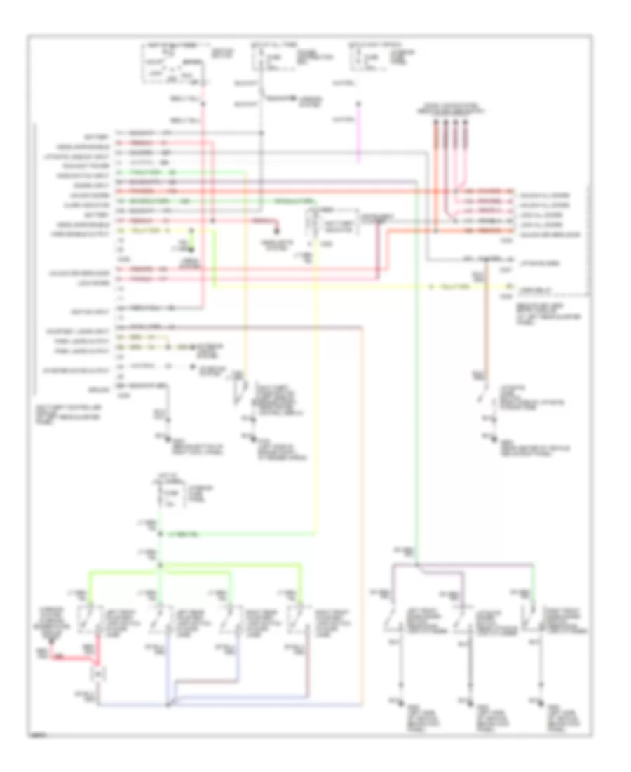
ANTI-LOCK BRAKES
Anti-lock Brake Wiring Diagrams for Ford Explorer 1994
 https://portal-diagnostov.com/license.html
Automotive Electricians Portal FZCO
Automotive Electricians Portal FZCO
https://portal-diagnostov.com/license.html
https://portal-diagnostov.com/license.html
Automotive Electricians Portal FZCO
Automotive Electricians Portal FZCO
List of elements for Anti-lock Brake Wiring Diagrams for Ford Explorer 1994:
- (at left front wheel)
- (at right front wheel)
- 4wabs control module (left rear corner of engine compartment)
- 4wabs data link connector (left side of engine compartment)
- 4wabs hydraulic unit (left side of engine compartment)
- 4wabs pump motor (left side of engine compart- ment)
- 4wabs relay #1
- 4wabs relay #2
- Acceleration sensor (left frame rail, under driver's seat)
- Anti-lock brakes indicator
- Brake on/off (boo) switch (on brake pedal support)
- Brake on/off sw feed
- C126
- C202
- C214
- C222
- Chassis rolls database
- Diag trigger circuit
- Dump valve
- Fuse
- Fuse 10a
- Fuse 15a
- Fuse 30a
- G-switch #1
- G-switch status
- G104 (left side of engine comparment at fender apron)
- G104 (left side of engine compartment at fender apron)
- G108 (left front of engine compart- ment)
- Ground
- Hazard flasher (part of interior fuse panel)
- Hot at all times
- Hot in run
- Hot in run or start
- Ignition
- Instrument cluster
- Interior fuse panel
- Iso valve
- Left front
- Left front dump valve
- Left front iso valve
- Left front sensor (hi)
- Left front sensor (lo)
- Left front wheel 4wabs sensor
- Limited edition and electronic group only
- Motor speed sens #1
- Motor speed sens #2
- Nca
- Pnk
- Power distribution box
- Powertrain control module (at right kick panel)
- Pump motor rly coil (-) g-switch #2
- Rear
- Rear axle sensor (on axle assembly)
- Rear dump valve
- Rear iso valve
- Rear sensor (hi)
- Rear sensor (lo)
- Relay coil (-)
- Right front
- Right front dump valve
- Right front iso valve
- Right front sensor (hi)
- Right front sensor (lo)
- Right front wheel 4wabs sensor
- Tan
- Tan/red
- Vehicle power
- Warning lamp
ANTI-THEFT
Anti-theft Wiring Diagram for Ford Explorer 1994
List of elements for Anti-theft Wiring Diagram for Ford Explorer 1994:
- Acc
- Alarm indicator
- Anti-theft controller module (at left rear quarter panel)
- Anti-theft hood switch (left side of engine compt, near cruise control servo)
- Anti-theft indicator
- Battery
- C222
- C336
- C337
- C338
- C339
- C340
- Courtesy lamps input
- Disarm input
- Door locks system (remote keyless entry)
- Exterior lights system
- Fuse 10a
- Fuse 15a
- Fuse 30a
- G104 (left side of engine compt., at fender apron)
- G200 (left side of vehicle, behind kick panel)
- G203 (behind bottom of right cowl panel)
- G909 (rear center of vehicle, above roof panel)
- Ground
- Headlamps enable
- Headlights system
- Hood switch input
- Horn enable output
- Horn relay
- Horns system
- Hot at all times
- Hot in accy or run
- Ignition input
- Ignition switch
- Instrument cluster
- Interior fuse panel
- Left front courtesy lamp switch (in door jamb)
- Left front door disarm switch (near door lock cylinder)
- Left rear courtesy lamp switch (in door jamb)
- Liftgate disarm switch (near liftgate lock cylinder)
- Liftgate jamb sw input
- Liftgate jamb switch (right side of liftgate, in door jamb)
- Liftgate open
- Lock
- Lock all doors
- Lock doors
- Mirrors system
- Off
- Park lamps output
- Power distribution box
- Red/ pnk
- Remote keyless entry module (at left rear quarter panel)
- Right front courtesy lamp switch (in door jamb)
- Right front door disarm switch (near door lock cylinder)
- Right rear courtesy lamp switch (in door jamb)
- Run
- Run/accy power
- Start
- Starter motor output
- Starting system
- Unlock all doors
- Unlock doors
- Unlock driver's door
- Warning system (warning buzzer/chime module pin #2)
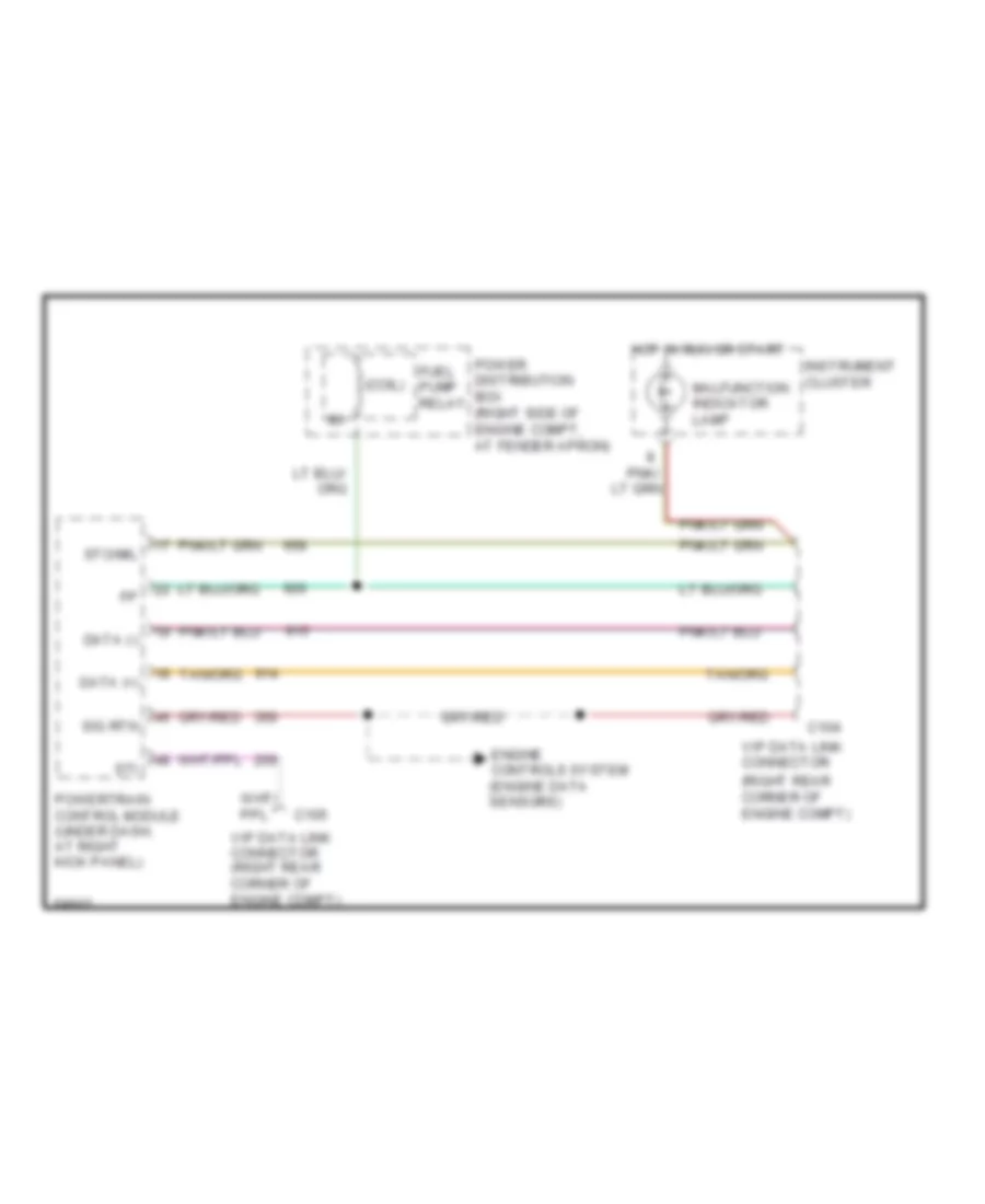
COMPUTER DATA LINES
Data Link Connector Wiring Diagram for Ford Explorer 1994
List of elements for Data Link Connector Wiring Diagram for Ford Explorer 1994:
- (coil)
- (right rear corner of engine compt)
- C104
- C105
- Data (+)
- Data (-)
- Engine controls system (engine data sensors)
- Fuel pump relay
- Hot in run or start
- Instrument cluster
- Malfunction indicator lamp
- Pnk/
- Power distribution box (right side of engine compt, at fender apron)
- Powertrain control module (under dash, at right kick panel)
- Sig rtn
- Sti
- Sto/mil
- Vip data link connector
- Vip data link connector (right rear corner of engine compt)
CRUISE CONTROL
4.0L
4.0L, Cruise Control Wiring Diagram for Ford Explorer 1994
List of elements for 4.0L, Cruise Control Wiring Diagram for Ford Explorer 1994:
- (attached to transmission)
- (behind left side of instrument panel, taped to main harness)
- (behind steering column)
- (connects to throttle linkage)
- (left side of engine, at fender apron)
- (on clutch pedal arm)
- (right side of
- (under right side
- 15a
- 40-
- 50,000 ohms
- 60-
- A/t
- Accel
- Actuator
- All
- Amp disable input
- Amp feedback
- Amp input
- Brake on/off (boo) switch
- Clock- ring
- Clutch triple function switch
- Clutch triple function switch jumper
- Coast
- Common
- Control switch input
- Cruise control amplifier (behind right side of instrument panel)
- Cruise control servo
- Engine controls system
- Fast
- Fuse 4
- Fuse 6 10a
- G201
- G203
- Ground
- Hazard flasher (part of interior fuse panel)
- Horn
- Horns system
- Hot at all times
- Hot in accy or run
- Instrument panel,
- Interior fuse panel
- Keyless entry system
- Limited edition
- Limited edition & electronic group only
- M/t
- Mounted to right side of kick panel)
- Of dash, above pcm)
- Off
- Ohms
- Others
- Overhead console system
- Pnk/
- Remote keyless entry & anti-theft systems
- Resume
- Servo feedback
- Servo motor
- Set/
- Slow
- Sol+
- Speed control/ horn switch (in steering column assembly)
- Speed sensor input
- Vac
- Vac solenoid
- Vacuum distri- bution
- Vacuum dump valve (vents to atmosphere when brake is depressed)
- Vehicle power
- Vehicle speed sensor (vss) (200-300 ohms)
- Vent
- Vent solenoid
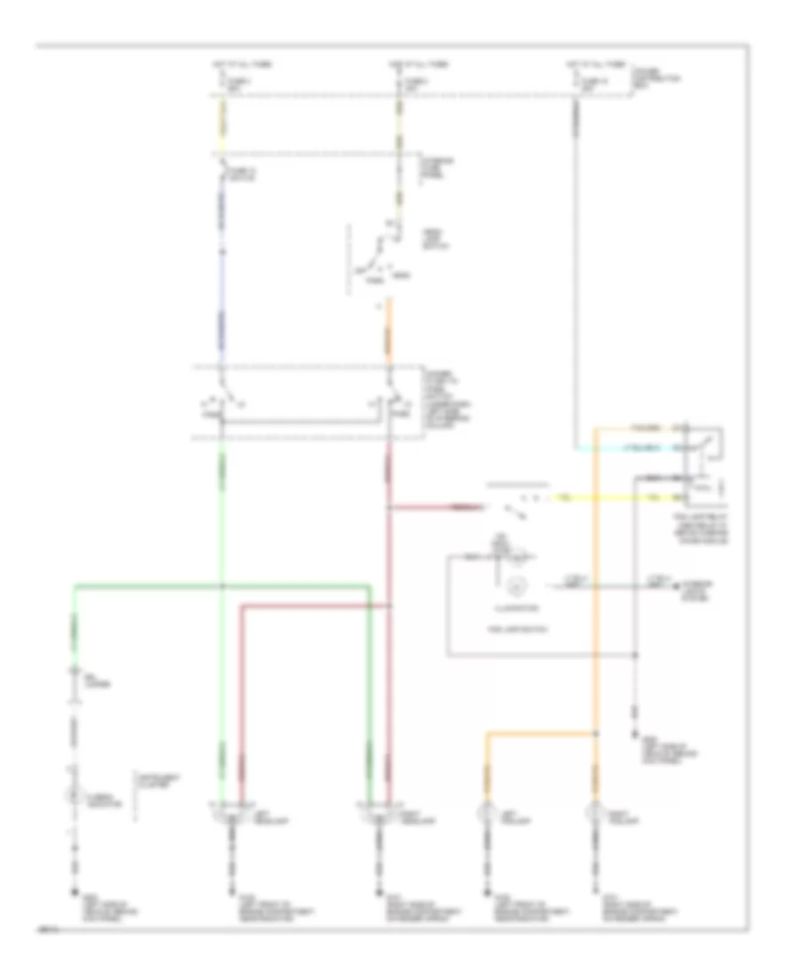
DEFOGGERS
Defogger Wiring Diagram for Ford Explorer 1994
List of elements for Defogger Wiring Diagram for Ford Explorer 1994:
- (left rear corner of vehicle) g411
- (left side of vehicle, behind kick panel)
- (left side of vehicle, behind kick panel) g200
- (right side of i/p, mounted to right side of kick panel)
- Fuse 10a
- Fuse 15a
- Fuse 40a
- G200
- G203
- Heated rear window switch
- Hot at all times
- Hot in run
- Interior fuse panel
- Interior lights system
- Left power/ heated mirror
- Limited edition & electronic group
- Limited edition only
- Off switch
- On indicator
- On switch
- Only
- Power distribution box
- Rear window defrost grid
- Relay
- Right power/ heated mirror
- Timing circuit
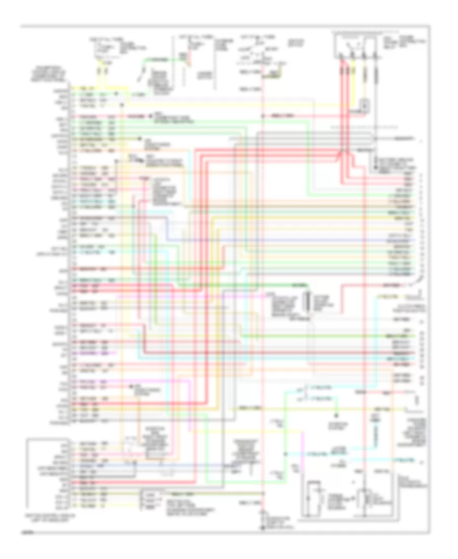
ENGINE PERFORMANCE
4.0L
4.0L, Engine Performance Wiring Diagrams (1 of 2) for Ford Explorer 1994
List of elements for 4.0L, Engine Performance Wiring Diagrams (1 of 2) for Ford Explorer 1994:
- (not used)
- 3-4 shift solenoid
- A/t
- A4ld automatic transmission
- Acc
- Accs
- Air conditioning system
- All others
- Boo
- Brake on/off switch (behind steering column)
- C104
- C105
- C126
- Canister purge solenoid (left front corner of engine compartment)
- Canp
- Capacitor (left of ignition coil)
- Ckp sens feed
- Ckp sens rtn
- Clutch pedal position switch
- Cmp
- Coil a
- Coil b
- Coil c
- Cpp m/t-pnp a/t
- Crankshaft position sensor (lower front of engine compartment)
- Cse gnd
- Data (+)
- Data (-)
- Diode
- Dpfe
- Ect
- Evr
- Fpm
- Fuse 4 15a
- Fuse 4 30a
- G201 (mounted to right side of kick panel)
- G201 (under right side of dash, above pcm)
- Gnd
- H2os 1
- H2os 2
- Hazard switch
- Hot at all times
- Iac
- Iat
- Idm
- Ign gnd
- Ignition coil (top left side of engine compartment, above valve cover)
- Ignition control module (left of headlamp)
- Ignition switch
- Inj 1
- Inj 2
- Inj 3
- Inj 4
- Inj 5
- Inj 6
- Interior fuse panel
- Kapwr
- Limited edition
- Lock
- M/t
- Maf
- Maf rtn
- Oct adj
- Octane adjust (shorting bar)
- Off
- Pcm power relay
- Pip
- Pnk
- Power distribution box
- Powertrain control module (under dash, at right kick panel)
- Pwr gnd
- Red
- Run
- Shorting bar (right front of engine compartment, near icm)
- Sig rtn
- Spout
- Start
- Starting system
- Sti
- Sto/mil
- Tan
- Tcc
- Torque converter clutch solenoid
- Vip data link connector (right rear corner of engine compartment)
- Vip data link connector (right rear corner of engine compt)
- Vpwr
- Vref
- Vss (+)
- Vss (-)
- Wac
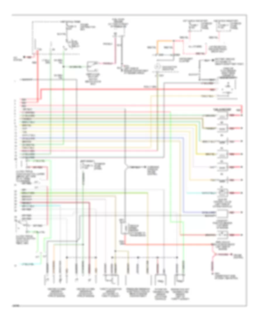
4.0L, Engine Performance Wiring Diagrams (2 of 2) for Ford Explorer 1994
List of elements for 4.0L, Engine Performance Wiring Diagrams (2 of 2) for Ford Explorer 1994:
- A/c system
- A/t
- All others
- C221
- C222
- Camshaft position sensor (top rear of engine)
- Clutch triple function switch (on clutch pedal arm)
- Clutch triple function switch jumper (behind left side of i/p, taped to harness)
- Cruise control
- Egr vacuum regulator solenoid (left side of engine)
- Engine coolant temperature sensor (left of throttle body)
- Fuel injectors
- Fuel pump relay
- Fuel pump/ sender (at tank in front of rear axle)
- Fuse 17 15a
- Fuse 18 15a
- Fuse 18 20a
- Fuse 7 15a
- G104 (left side of engine compartment at fender apron)
- G201 (under right side of dash, above pcm)
- Heated oxygen sensor #1 (on exhaust pipe of engine)
- Heated oxygen sensor #2 (on exhaust pipe of engine)
- Hot at all times
- Hot in run
- Hot in run and start
- Idle air control valve (left side of intake manifold)
- Inertia fuel shut-off switch (below glove box)
- Instrument cluster
- Intake air temperature sensor (on intake manifold)
- Interior fuse panel
- Limited edition and electronic group only
- M/t
- Malfunction indicator
- Mass air flow sensor (right rear corner of engine compt)
- Overhead console/ cruise control
- Power distribution box
- Pressure feedback electronic module (rear of engine compartment)
- Red
- Tan
- Throttle position sensor (attached to throttle body)
- Vehicle speed sensor (attached to transmission)
EXTERIOR LIGHTS
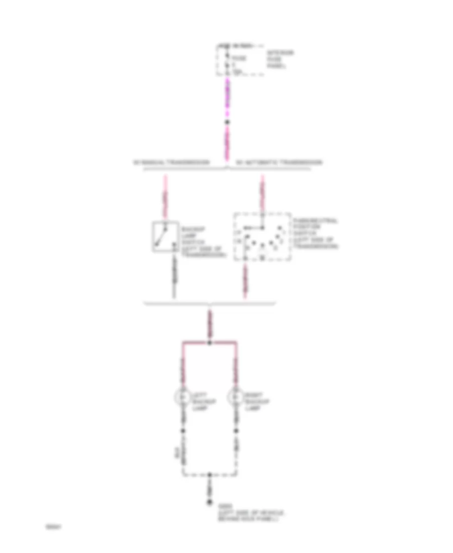
Backup Lamps Wiring Diagram for Ford Explorer 1994
List of elements for Backup Lamps Wiring Diagram for Ford Explorer 1994:
- Backup lamp switch (left side of transmission)
- Fuse 15a
- G200 (left side of vehicle, behind kick panel)
- Hot in run
- Interior fuse panel
- Left backup lamp
- Park/neutral position switch (left side of transmission)
- Right backup lamp
- W/ automatic transmission
- W/ manual transmission
Exterior Lamps Wiring Diagram for Ford Explorer 1994
List of elements for Exterior Lamps Wiring Diagram for Ford Explorer 1994:
- 4wabs control module (left rear corner of engine compartment)
- All others
- Anti-theft controller module (limited edition & electronic group only) (inside left quarter panel)
- Brake on/off switch
- Brake on/off switch (behind steering column)
- Brake on/off switch feed
- C186
- C209
- C216
- C221
- C222
- C255
- C336
- Clutch triple function switch (on clutch pedal arm)
- Cruise control amplifier (behind right side of i/p)
- Disable input
- Exterior lamps output
- Fuse 15a
- G101 (right side of engine compartment, attached to right quarter panel)
- G108 (left front of engine compartment, near radiator)
- G200 (left side of vehicle, behind kick panel)
- Hazard
- Hazard flasher (part of interior fuse panel)
- Head
- Headlamp switch
- High mount stop lamp
- Hot at all times
- Hot in run
- Instrument cluster
- Interior fuse panel
- Left front park/ turn lamp
- Left front side marker lamp
- Left rear stop/ park/ turn lamp
- Left turn indicator
- License lamps
- Liftgate disarm switch (near liftgate lock cylinder)
- Limited edition & electronic group only
- Limited edition only
- Limited edition/ electronic group & standard 2 door
- Limited edition/electronic group & standard 2 door
- Normal
- Off
- Park
- Powertrain control module (right kick panel, under i/p)
- Right front park/ turn lamp
- Right front side marker lamp
- Right rear stop/ park/ turn lamp
- Right turn indicator
- Standard 4 door only
- Trailer/camper adapter circuit (left stop/turn signal relay)
- Trailer/camper adapter circuit (right stop/turn signal relay)
- Trailer/camper adapter circuit (tail lamp relay)
- Turn left
- Turn right
- Turn signal flasher (part of interior fuse panel)
- Turn/hazard switch (left side of steering column)
- W/ trailer option
- W/o trailer option
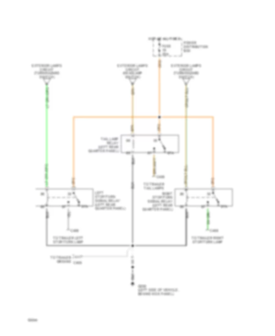
Trailer/Camper Adapter Wiring Diagram for Ford Explorer 1994
List of elements for Trailer/Camper Adapter Wiring Diagram for Ford Explorer 1994:
- 87a
- C408
- Exterior lamps circuit (headlamp switch)
- Exterior lamps circuit (turn/hazard switch)
- Fuse 20a
- G200 (left side of vehicle, behind kick panel)
- Hot at all times
- Left stop/turn signal relay (left rear quarter panel)
- Power distribution box
- Right stop/turn signal relay (left rear quarter panel)
- Tail lamp relay (left rear quarter panel)
- To trailer left stop/turn lamp
- To trailer right stop/turn lamp
- To trailer tail lamps
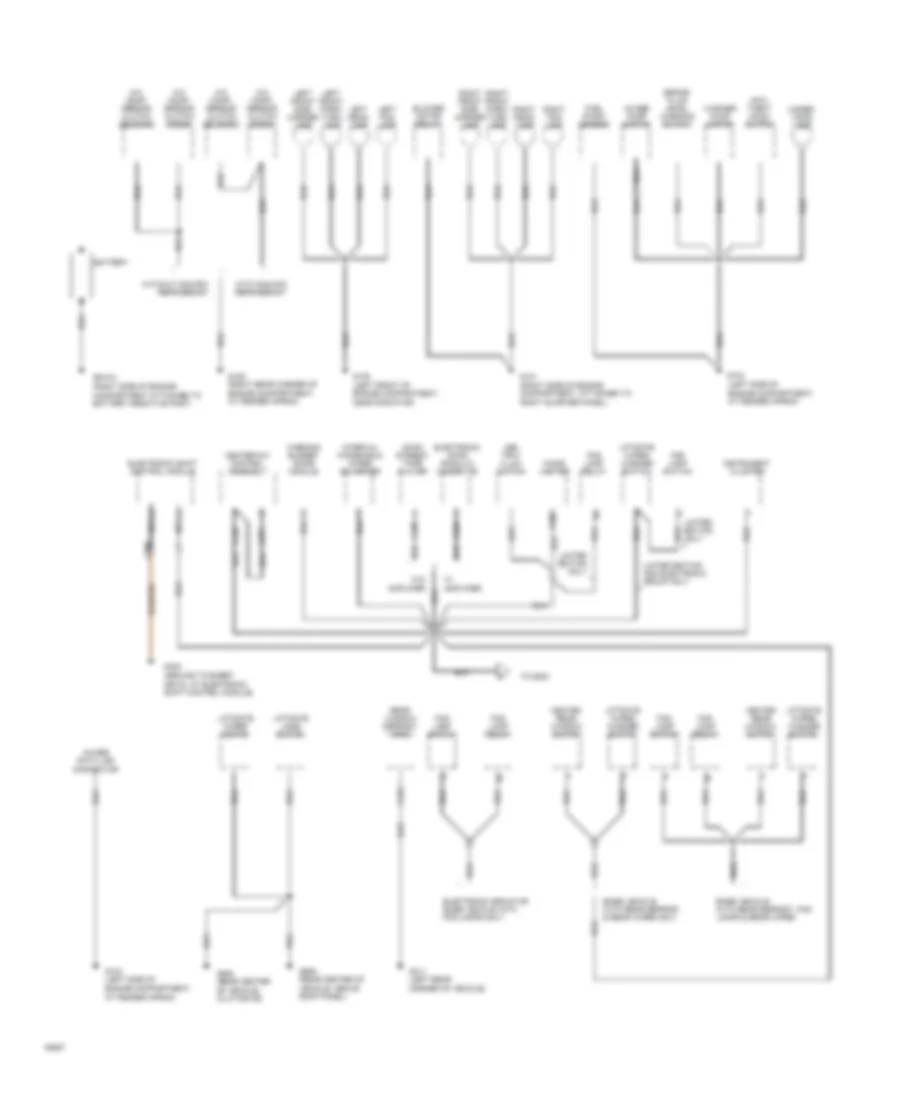
GROUND DISTRIBUTION
Ground Distribution Wiring Diagram (1 of 3) for Ford Explorer 1994
List of elements for Ground Distribution Wiring Diagram (1 of 3) for Ford Explorer 1994:
- (ground to sheet metal at electronic shift control module)
- (right side of engine compartment, attached to right quarter panel)
- 4wabs data link connector
- 4wabs pump motor
- A/c comp- ressor clutch diode
- A/c comp- ressor clutch solenoid
- Am/fm stereo/ tape player
- Anti- theft hood switch
- Ash tray illum- ination
- Base vehicle with rear defrost & rear wiper only
- Base vehicle with rear defrost, fog lamps & rear wiper
- Battery
- Blower motor relay
- Brake fluid level warning switch
- C206
- C228
- C230
- C231
- C302
- C421
- Cigar lighter
- Electronic am/fm radio w/ cassette
- Electronic group or base vehicle with fog lamps only
- Electronic shift control module
- Fog lamp relay
- Fog lamp switch
- Fuel pump/ sender
- G# n/a
- G101
- G104 (left side of engine compartment, at fender apron)
- G105 (right rear corner of engine compartment, at fender apron)
- G108 (left front of engine compartment, near radiator)
- G402
- G406 (rear center of vehicle, in liftgate)
- G411 (left rear corner of vehicle)
- G909 (rear center of vehicle, above roof panel)
- Heated rear window switch
- Heater-a/c control assembly
- Instrument cluster
- Interval windshield wiper governer
- Left fog lamp
- Left front park/ turn lamp
- Left front side marker lamp
- Left head- lamp
- Liftgate jamb switch
- Liftgate wiper motor
- Liftgate wiper/ washer switch
- Limited edition and electronic group only
- Limited edition only
- Nca
- Rear window defrost grid
- Right fog lamp
- Right front park/ turn lamp
- Right front side marker lamp
- Right head- lamp
- To g200
- Under- hood lamp
- W/ amplifier
- W/o amplifier
- Warning buzzer/ chime module
- Washer pump motor
- With non-cfc refrigerant
- Without non-cfc refrigerant
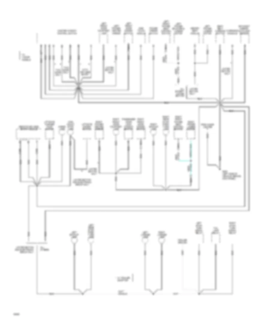
Ground Distribution Wiring Diagram (2 of 3) for Ford Explorer 1994
List of elements for Ground Distribution Wiring Diagram (2 of 3) for Ford Explorer 1994:
- (left front of engine compartment
- (right side of instrument panel, mounted to
- 4wabs control module
- 4wabs relay #1
- Am/fm stereo/ tape
- Amplifier
- Anti- theft controller module
- Battery ground (right side of engine compartment, attached to
- C221
- C222
- C228
- C260
- C332
- C333
- C337
- C338
- Camshaft position sensor
- Cruise control amplifier
- Cruise control/ horn switch
- Electronic am/fm radio w/ cassette
- Electronic shift control switches
- Fuel pump/ sender
- G108
- G201 (right side of vehicle, behind kick panel)
- G201 (right side of instrument panel, mounted to right side of kick panel)
- G201 (under right side of dash, above pcm)
- G203
- Glove box lamp & switch
- Headlamp switch
- Heated oxygen sensor #1
- Heated oxygen sensor #2
- Heated rear window switch
- Ignition control module
- Instrument cluster
- Limited edition and electronic group only
- Limited edition only
- Low oil level relay
- Mass air flow sensor
- Memory seat module
- Nca
- Near radiator)
- Pcm power relay
- Player
- Powertrain control module
- Remote keyless entry module
- Right side of kick panel)
- Sub- woofer amplifier
- Vehicle speed sensor
- W/ amplifier
- W/o amplifier
Ground Distribution Wiring Diagram (3 of 3) for Ford Explorer 1994
List of elements for Ground Distribution Wiring Diagram (3 of 3) for Ford Explorer 1994:
- * w/ 4 door models
- Adaptor
- All except limited edition
- All others
- C339
- C340
- Cargo lamp
- Day/night mirror/ autolamp sensor
- From cigar lighter
- G200 (left side of vehicle, behind kick panel)
- High mount stop lamp
- Left backup lamp
- Left front door courtesy lamp
- Left front door disarm switch
- Left front power seat control switch
- Left license lamp
- Left power bolster & lumbar motor
- Left power lumbar motor
- Left power/ heated mirror
- Left rear stop/ park/ turn/ lamp
- Left stop/ turn signal relay
- Liftgate disarm switch
- Liftgate washer pump motor
- Limited edition only
- Limited edition and electronic group only
- Limited edition only
- Master window control switch
- Memory seat module
- Nca
- One- touch module
- Overhead console
- Passenger door lock/ window switch
- Power mirror switch
- Remote keyless entry module
- Right backup lamp
- Right front door courtesy lamp
- Right front door disarm switch
- Right front power seat control switch
- Right license lamp
- Right power lumbar motor
- Right power/ heated mirror
- Right rear stop/ park/ turn/ lamp
- Right stop/ turn signal relay
- Seat belt warning switch
- Tail lamp relay
- Trailer ground
- Two door only
- W/ trailer *
- With keyless entry
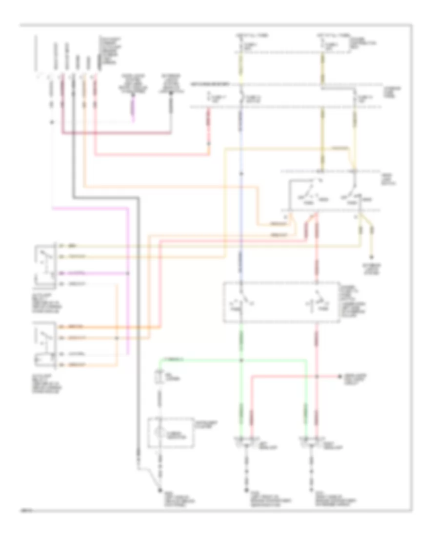
HEADLIGHTS
Headlamps Wiring Diagram, with Autolamps for Ford Explorer 1994
List of elements for Headlamps Wiring Diagram, with Autolamps for Ford Explorer 1994:
- (under dash, left side of steering column)
- Autolamp relay 1 (center of i/p, above warning chime module)
- Autolamp relay 2 (center of i/p, above warning chime module)
- Back-up input
- Day/night mirror/ autolamp sensor (in rear- view mirror)
- Dimmer/ flash to pass switch
- Door locks system (keyless entry module) (if equipped)
- Drl jumper
- Exterior lights system
- Exterior lights system (back-up lamp switch)
- Fuse 10 15a
- Fuse 12 20a c.b.
- Fuse 17 15a
- Fuse 2 40a
- Fuse 3 60a
- G101 (right side of engine compartment, on fender apron)
- G108 (left front of engine compartment, near radiator)
- G200 (left side of vehicle, behind kick panel)
- Ground
- Head
- Head- lamp switch
- Headlamps/ fog lamps circuit
- Hi beam indicator
- Hot at all times
- Hot in run or start
- Ignition
- Instrument cluster
- Interior fuse panel
- Left headlamp
- Off
- Park
- Pass
- Power
- Power distribution box
- Relay output
- Right headlamp
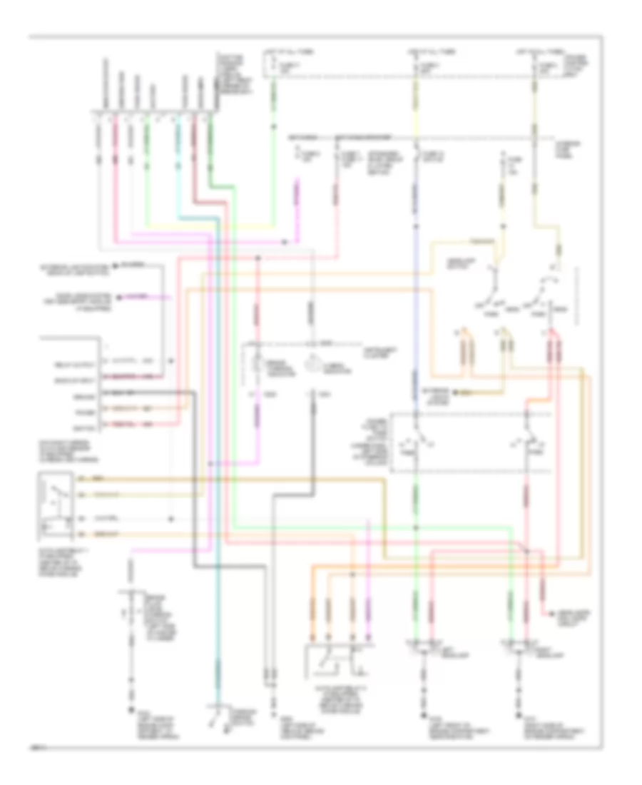
Headlamps Wiring Diagram, with DRL for Ford Explorer 1994
List of elements for Headlamps Wiring Diagram, with DRL for Ford Explorer 1994:
- (if equipped)
- (standard) (elec. group & limited edition)
- (under dash, left side of steering column)
- Autolamp relay 1 (if equipped) (center of i/p, above warning chime module)
- Autolamp relay 2 (if equipped) (center of i/p, above warning chime module)
- Back-up input
- Battery
- Brake fluid level warning switch (left side of master cylinder)
- Brake warning indicator
- C221
- C222
- Day/night mirror/ autolamp sensor (if equipped) (in rear-view mirror)
- Daytime running lamps module (left front corner of engine bay)
- Dimmer/ flash to pass switch
- Door locks system (keyless entry module)
- Exterior lights system
- Exterior lights system (back-up lamp switch)
- Fuse 12 20a c.b.
- Fuse 15a
- Fuse 17 15a
- Fuse 2 40a
- Fuse 3 60a
- Fuse 5 15a
- Fuse 7 fuse 17 15a
- G101 (right side of engine compartment, on fender apron)
- G104 (left side of engine comp- artment, at fender apron)
- G108 (left front of engine compartment, near radiator)
- G200 (left side of vehicle, behind kick panel)
- Ground
- Head
- Headlamp switch
- Headlamps
- Headlamps/ fog lamps circuit
- Hi beam indicator
- Hot at all times
- Hot in run
- Hot in run or start
- Ignition
- Ignition feed
- Indicator output
- Instrument cluster
- Interior fuse panel
- Left headlamp
- Off
- Park
- Park brake
- Parking brake switch
- Pass
- Power
- Power distrib- ution box
- Relay output
- Right headlamp
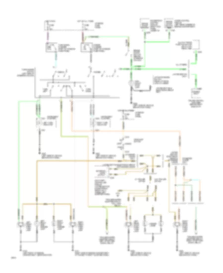
Headlamps/Fog Lamps Wiring Diagram for Ford Explorer 1994
List of elements for Headlamps/Fog Lamps Wiring Diagram for Ford Explorer 1994:
- 'on' indic- ator
- (center of i/p, above warning chime module)
- (under dash, left side of steering column)
- Dimmer/ flash to pass switch
- Drl jumper
- Fog lamp relay
- Fog lamp switch
- Fuse 12 20a c.b.
- Fuse 15 20a
- Fuse 2 40a
- Fuse 3 60a
- G101 (right side of engine compartment, on fender apron)
- G108 (left front of engine compartment, near radiator)
- G200 (left side of vehicle, behind kick panel)
- Head
- Head- lamp switch
- Hi beam indicator
- Hot at all times
- Illumination
- Instrument cluster
- Interior fuse panel
- Interior lights system
- Left foglamp
- Left headlamp
- Off
- Park
- Pass
- Power distribution box
- Red
- Right foglamp
- Right headlamp
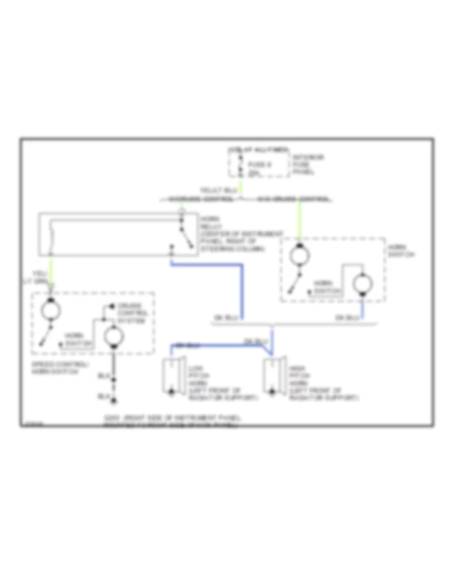
HORN
Horn Wiring Diagram for Ford Explorer 1994
List of elements for Horn Wiring Diagram for Ford Explorer 1994:
- (right side of instrument panel,
- 20a
- Cruise control system
- Fuse 8
- G203 mounted to right side of kick panel)
- High pitch horn (left front of radiator support)
- Horn relay (center of instrument panel, right of steering column)
- Horn switch
- Hot at all times
- Interior fuse panel
- Low pitch horn (left front of radiator support)
- Speed control/ horn switch
- W/cruise control
- W/o cruise control
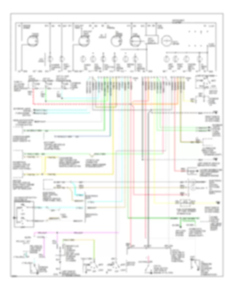
INSTRUMENT CLUSTER
Instrument Cluster Wiring Diagram for Ford Explorer 1994
List of elements for Instrument Cluster Wiring Diagram for Ford Explorer 1994:
- (at left rear
- (dimmer/flash
- (left side of engine compt, at fender apron)
- (left side of vehicle, behind kick panel)
- (not used)
- (right front
- (right rear corner of engine compt)
- (right side of i/p, right side of kick panel)
- (turn/hazard
- 4wabs control module (left rear corner of engine compt)
- 4wabs data link connector (left side of engine compt)
- 4x2
- 4x4
- 4x4 high
- 4x4 high range ind.
- 4x4 indicator switch (mounted on transfer case)
- 4x4 low
- 4x4 low range ind.
- A10
- A11
- A12
- A13
- A14
- Acc
- Alternator/
- Anti- lock brakes ind.
- Anti- slosh module
- Anti- theft ind.
- Anti-lock brakes system
- Anti-theft
- B10
- B11
- B12
- B13
- B14
- Bat
- Brake fluid level warning switch (on left side of brake master cylinder)
- Brake ind.
- Charge warning ind.
- Check oil ind.
- Conn
- Controller module
- Coolant temp.
- Coolant temp. gauge
- Drl module (left front corner of engine)
- Electronic shift
- Electronic shift control module (rear of vehicle, over wheel well)
- Electronic shift control switches (w/ electronic shift)
- Engine speed
- Exterior lights
- Exterior lights system (turn/ hazard switch)
- Fasten seat belts ind.
- Fuel gauge
- Fuel level
- Fuel pump/sender (at tank, in front
- Fuse 10a
- Fuse 15a
- Fuse 17- w/ limited edition & electronics group
- G104
- G200
- G201
- G203
- Gnd
- Headlights system
- Hi beam ind.
- Hot at all times
- Hot in run or start
- Hot w/ lamp switch in park or head
- Ign
- Ignition control module (right front corner of engine compt, left of headlamp)
- Ignition switch
- Illum.
- Illum. lamps
- Instrument cluster
- Interior fuse panel: i/p
- Left turn ind.
- Lock
- Low
- Low oil level relay (left side of dash, above interior fuse panel)
- Low oil level switch (left side of engine, at oil pan)
- Mal- function ind.
- Mechanical shift
- Of engine compt)
- Of rear axle)
- Off
- Ohms
- Oil press.
- Oil press. gauge
- Oil pressure switch (on engine, next to power steering pump)
- Parking brake switch
- Powertrain control module (under dash, at right kick panel)
- Quarter panel)
- Regulator
- Right turn ind.
- Run
- Start
- Switch)
- System
- Tacho- meter
- Tachometer test connector (right rear corner of engine compt, near blower motor)
- To pass switch)
- Vip data link connector
- Volt- meter
- W/ drl
- W/o drl
- Warning buzzer/ chime module (right side of i/p)
- Water temperature indicator sender (left front corner of engine)
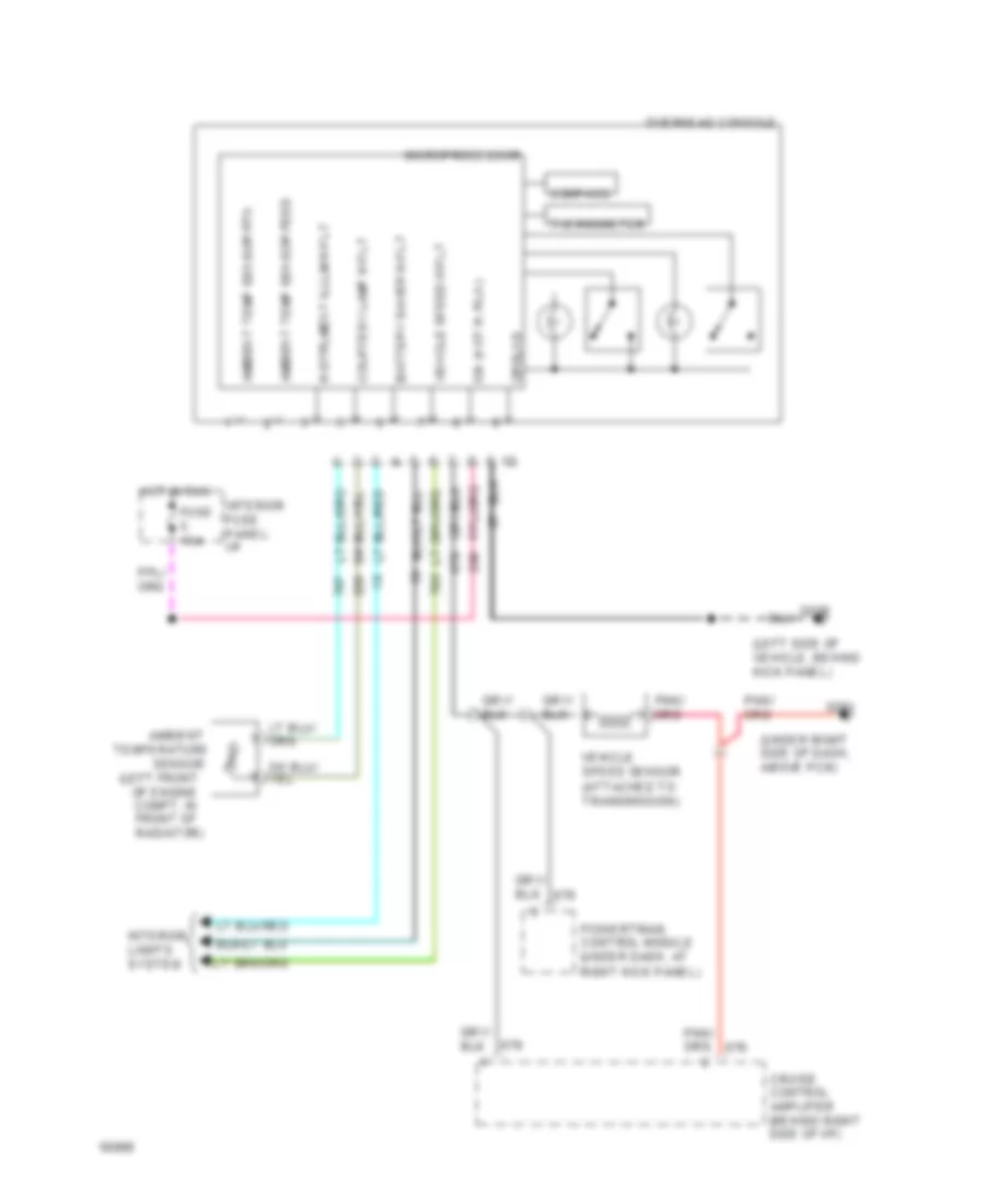
Overhead Console Wiring Diagram for Ford Explorer 1994
List of elements for Overhead Console Wiring Diagram for Ford Explorer 1994:
- (left front
- (left side of vehicle, behind kick panel)
- (under right side of dash, above pcm)
- Ambient
- Ambient temp sensor feed
- Ambient temp sensor rtn
- Battery saver input
- Compass
- Courtesy lamp input
- Cruise control amplifier (behind right side of i/p)
- Fuse 15a
- G200
- G201
- Ground
- Hot in run
- Ign (hot in run)
- Instrument illum input
- Interior fuse panel: i/p
- Interior lights system
- Microprocessor
- Of engine compt, in front of radiator)
- Overhead console
- Powertrain control module (under dash, at right kick panel)
- Sensor
- Temperature
- Thermometer
- Vehicle speed input
- Vehicle speed sensor (attached to transmission)
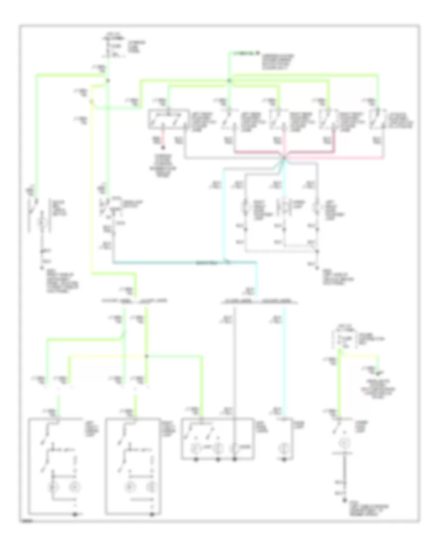
INTERIOR LIGHTS
Courtesy Lamps Wiring Diagram, Base for Ford Explorer 1994
List of elements for Courtesy Lamps Wiring Diagram, Base for Ford Explorer 1994:
- C216
- Cargo lamp
- Dome
- Dome lamp
- Fuse 15a
- G104 (left side of engine compartment, at fender apron)
- G200 (left side of vehicle, behind kick panel)
- G203 (right side of instrument panel, mounted to right side of kick panel)
- Glove box lamp & switch
- Headlamp switch
- Headlights system (daytime running lamps module pin #4)
- Hot at all times
- Interior fuse panel
- Left front courtesy lamp switch (in door jamb)
- Left front door courtesy lamp
- Left rear courtesy lamp switch (in door jamb)
- Left vanity mirror lamp
- Liftgate courtesy lamp switch (in liftgate)
- Map
- Map/ dome lamps
- Mirrors system (power mirror switch pin #4) (2 door only)
- Power distribution box
- Red/ pnk
- Right front courtesy lamp switch (in door jamb)
- Right front door courtesy lamp
- Right rear courtesy lamp switch (in door jamb)
- Right vanity mirror lamp
- Under hood lamp
- W/ map lamps
- W/o map lamps
- Warning system (warning buzzer/chime module pin #2)
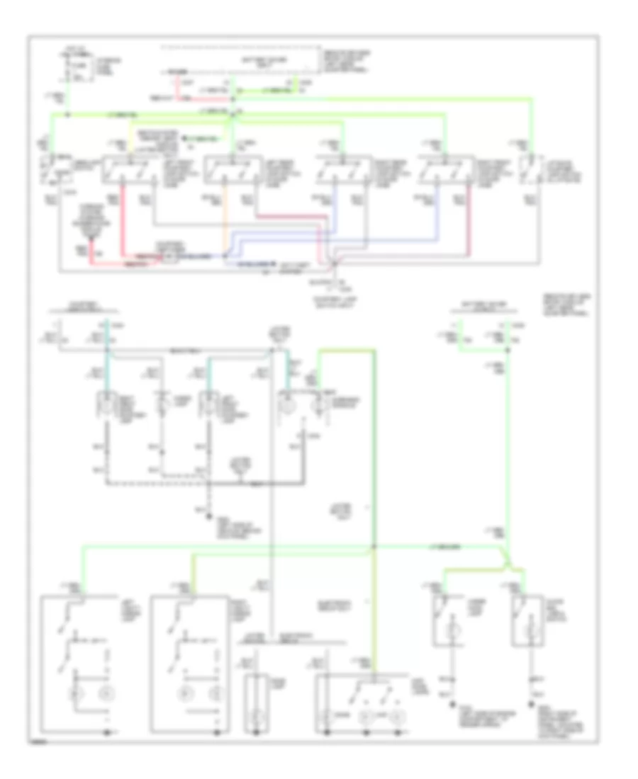
Courtesy Lamps Wiring Diagram, Limited Edition and Electronic Group for Ford Explorer 1994
List of elements for Courtesy Lamps Wiring Diagram, Limited Edition and Electronic Group for Ford Explorer 1994:
- Anti-theft system
- Battery saver input
- Battery saver output
- C216
- C337
- C339
- C340
- C342
- Cargo lamp
- Courtesy lamp diode
- Courtesy lamp output
- Courtesy lamp switch input
- Dome
- Dome lamp
- Electronic group
- Electronic group only
- Fuse 15a
- G104 (left side of engine compartment, at fender apron)
- G200 (left side of vehicle, behind kick panel)
- G203 (right side of instrument panel, mounted to right side of kick panel)
- Glove box lamp & switch
- Headlamp switch
- Hot at all times
- Interior fuse panel
- Left front courtesy lamp switch (in door jamb)
- Left front door courtesy lamp
- Left rear courtesy lamp switch (in door jamb)
- Left vanity mirror lamp
- Liftgate courtesy lamp switch (in liftgate)
- Limited edition
- Limited edition only
- Map
- Map/ dome lamps
- Overhead console
- Power
- Red/ pnk
- Red/pnk
- Remote keyless entry module (left rear quarter panel)
- Right front courtesy lamp switch (in door jamb)
- Right front door courtesy lamp
- Right rear courtesy lamp switch (in door jamb)
- Right vanity mirror lamp
- Seats system (memory seat module) (limited edition only)
- Under hood lamp
- Warning system (warning buzzer/chime module pin #2)
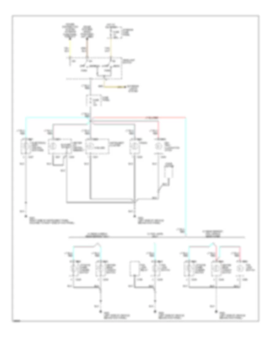
Instrument Illumination Wiring Diagram, Base for Ford Explorer 1994
List of elements for Instrument Illumination Wiring Diagram, Base for Ford Explorer 1994:
- (5 bulbs)
- Ash tray illumination -ation
- Blower switch
- C195
- C208
- C221
- C222
- C227
- C228
- C230
- C231
- C248
- C249
- C268
- Cigar lighter
- Electronic shift control switches
- Exterior lights system
- Fog lamp relay
- Fog lamp switch
- Fuse 10a
- Fuse 15a
- Fuse panel
- G200 (left side of vehicle, behind kick panel)
- G203 (right side of instrument panel, mounted to right side of kick panel)
- Head
- Headlamp switch
- Heated rear window switch
- Heater- a/c control assembly
- Hot at all times
- Ign
- Instrument cluster
- Interior fuse panel
- Liftgate wiper/ washer switch
- Off
- Park
- Power distribution system (interior fuse panel fuse #11)
- Radio
- Sound systems (radio pin #4/c228) (not used)
- W/ fog lamps only
- W/ rear defrost, fog lamps & rear wiper
- W/ rear wiper & rear defrost only
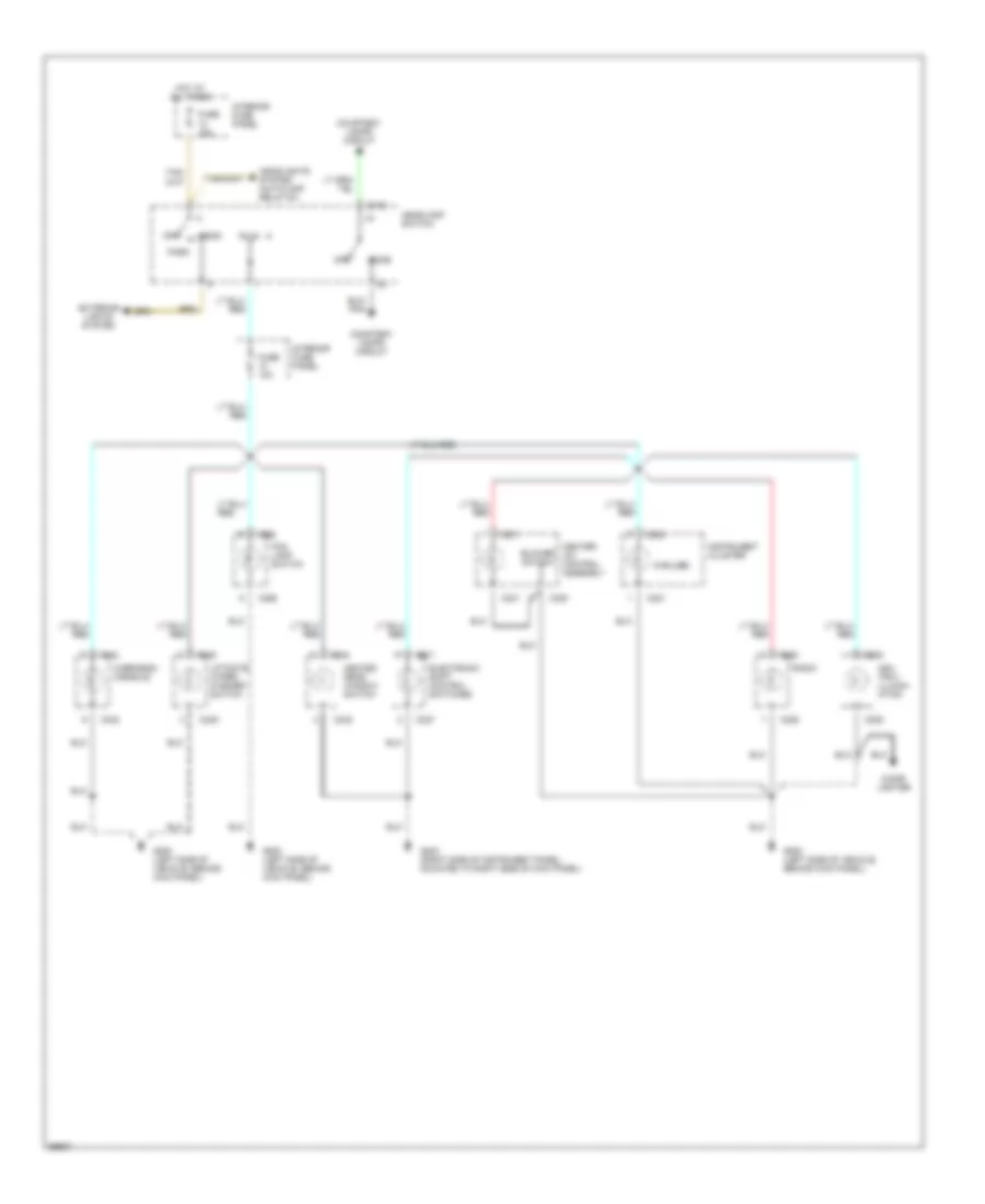
Instrument Illumination Wiring Diagram, Limited Edition and Electronic Group for Ford Explorer 1994
List of elements for Instrument Illumination Wiring Diagram, Limited Edition and Electronic Group for Ford Explorer 1994:
- (5 bulbs)
- Ash tray illumin- ation
- Blower switch
- C208
- C216
- C221
- C222
- C227
- C228
- C230
- C231
- C248
- C249
- C268
- C342
- Cigar lighter
- Courtesy lamps circuit
- Dome
- Electronic shift control switches
- Exterior lights system
- Fog lamp switch
- Fuse 10a
- Fuse 15a
- G200 (left side of vehicle, behind kick panel)
- G203 (right side of instrument panel, mounted to right side of kick panel)
- Head
- Headlamp switch
- Headlights system (autolamp relay #1)
- Heated rear window switch
- Heater- a/c control assembly
- Hot at all times
- Instrument cluster
- Interior fuse panel
- Liftgate wiper/ washer switch
- Off
- Overhead console
- Park
- Radio
- Red
POWER DISTRIBUTION
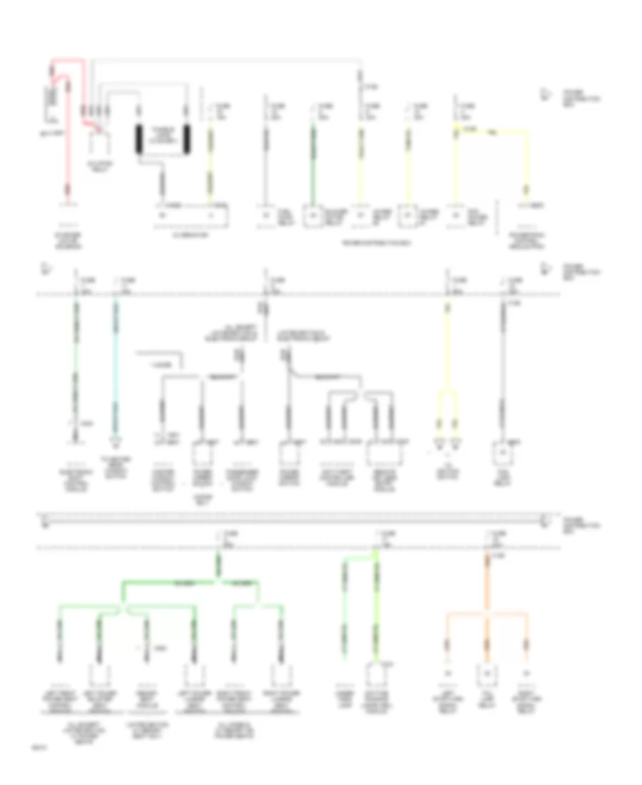
Power Distribution Wiring Diagram (1 of 5) for Ford Explorer 1994
List of elements for Power Distribution Wiring Diagram (1 of 5) for Ford Explorer 1994:
- * 4-door
- 4-door only
- 4wabs relay #1
- 4wabs relay #2
- All except limited edition & electronic group
- All except limited edition w/ power seats
- All models w/ memory or power seats
- Alternator
- Anti-theft controller module
- Battery
- Blower motor relay
- C121
- C122
- C126
- C134
- C202
- C259
- C302
- C338
- C340
- C350
- C501
- C507
- C601
- Daytime running lamps (drl) module
- Electronic shift control module
- Fog lamp relay
- Fuel pump relay
- Fuse 15a
- Fuse 20a
- Fuse 30a
- Fuse 40a
- Fuse 50a
- Fuse 60a
- Left front power seat control switch
- Left power bolster seat switch
- Left power lumbar seat switch
- Left stop/turn signal relay
- Limited edition & electronic group
- Limited edition w/ memory seat only
- Master window control switch
- Memory seat module
- Nca
- Passenger door lock/ window switch
- Pcm power relay
- Power distribution box
- Power mirror switch
- Powertrain control module (pcm)
- Red
- Remote keyless entry module
- Right front power seat control switch
- Right power lumbar seat switch
- Right stop/turn signal relay
- Starter relay
- Starter/ motor solenoid
- Tail lamp relay
- To heated rear window switch
- To ignition switch
- Under- hood lamp
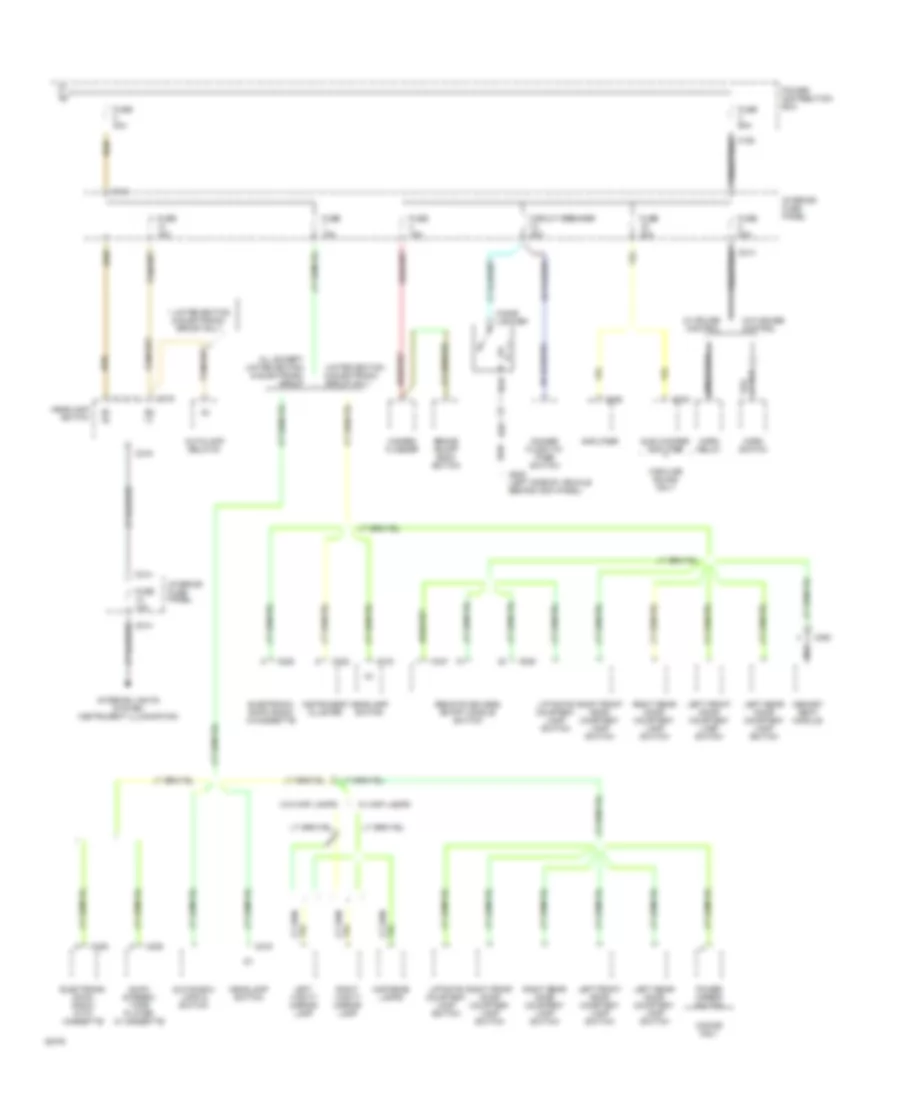
Power Distribution Wiring Diagram (2 of 5) for Ford Explorer 1994
List of elements for Power Distribution Wiring Diagram (2 of 5) for Ford Explorer 1994:
- * limited edition & electronic group only
- 2-door only
- All except limited edition & electronic group
- Am/fm stereo/ tape player w/ cassette
- Amplifier
- Autolamp relay #1
- B1 b *
- B2 a *
- Brake on/off (boo) switch
- C124
- C214
- C216
- C222
- C228
- C332
- C333
- C337
- C339
- C350
- Cigar lighter
- Circuit breaker 20a
- Dimmer flash-to- pass switch
- Electronic am/fm radio w/cassette
- Electronic am/fm radio with cassette
- Fuse 10a
- Fuse 15a
- Fuse 20a
- Fuse 40a
- Fuse 60a
- G200 (left side of vehicle behind kick panel)
- Glove box lamp & switch
- Hazard flasher
- Headlamp switch
- Highline sound only
- Horn relay
- Horn switch
- Instrument cluster
- Interior fuse panel
- Interior lights system (instrument illumination)
- Left front door courtesy lamp switch
- Left rear door courtesy lamp switch
- Left vanity mirror lamp
- Liftgate courtesy lamp switch
- Limited edition & electronic group only
- Map/dome lamps
- Memory seat module
- Nca
- Power distribution box
- Power mirror switch
- Remote keyless entry module switch
- Right front door courtesy lamp switch
- Right rear door courtesy lamp switch
- Right vanity mirror lamp
- Sub woofer amplifier
- W/ cruise control
- W/ map lamps
- W/o cruise control
- W/o map lamps
Power Distribution Wiring Diagram (3 of 5) for Ford Explorer 1994
List of elements for Power Distribution Wiring Diagram (3 of 5) for Ford Explorer 1994:
- (not used)
- (power distribution box)
- * limited edition & electronic group only
- ** electronic group only
- 4wabs control module
- 4wabs relay #1
- Acc
- All except limited edition
- Anti-theft controller module
- C186
- C209
- C214
- C221
- C222
- C223
- C225
- C227
- C236
- C301
- C302
- C335
- C336
- C341
- Capacitor
- Clutch triple function switch (manual transmission) or clutch triple function jumper (automatic transmission)
- Day/night mirror/ autolamp sensor
- Diode
- Electronic shift control module
- Electronic shift control switches
- From fuse #1 (power distribution box)
- From fuse 11 g
- Fuse 10a
- Fuse 15a
- Heated oxygen sensor (h02s) #1
- Heated oxygen sensor (h02s) #2
- Heated rear window switch
- Ignition coil
- Ignition switch
- Instrument cluster
- Instrument cluster (charge warning indicator)
- Interior fuse panel
- Left power heated mirror
- Limited edition & electronic group only
- Limited edition only
- Lock
- Low oil level relay
- Memory seat module
- Off
- Pcm power relay
- Power distribution box
- Rear window defrost grid
- Right power heated mirror
- Run
- Start
- W/ automatic transmission
- W/ manual transmission
- Warning buzzer/ chime module
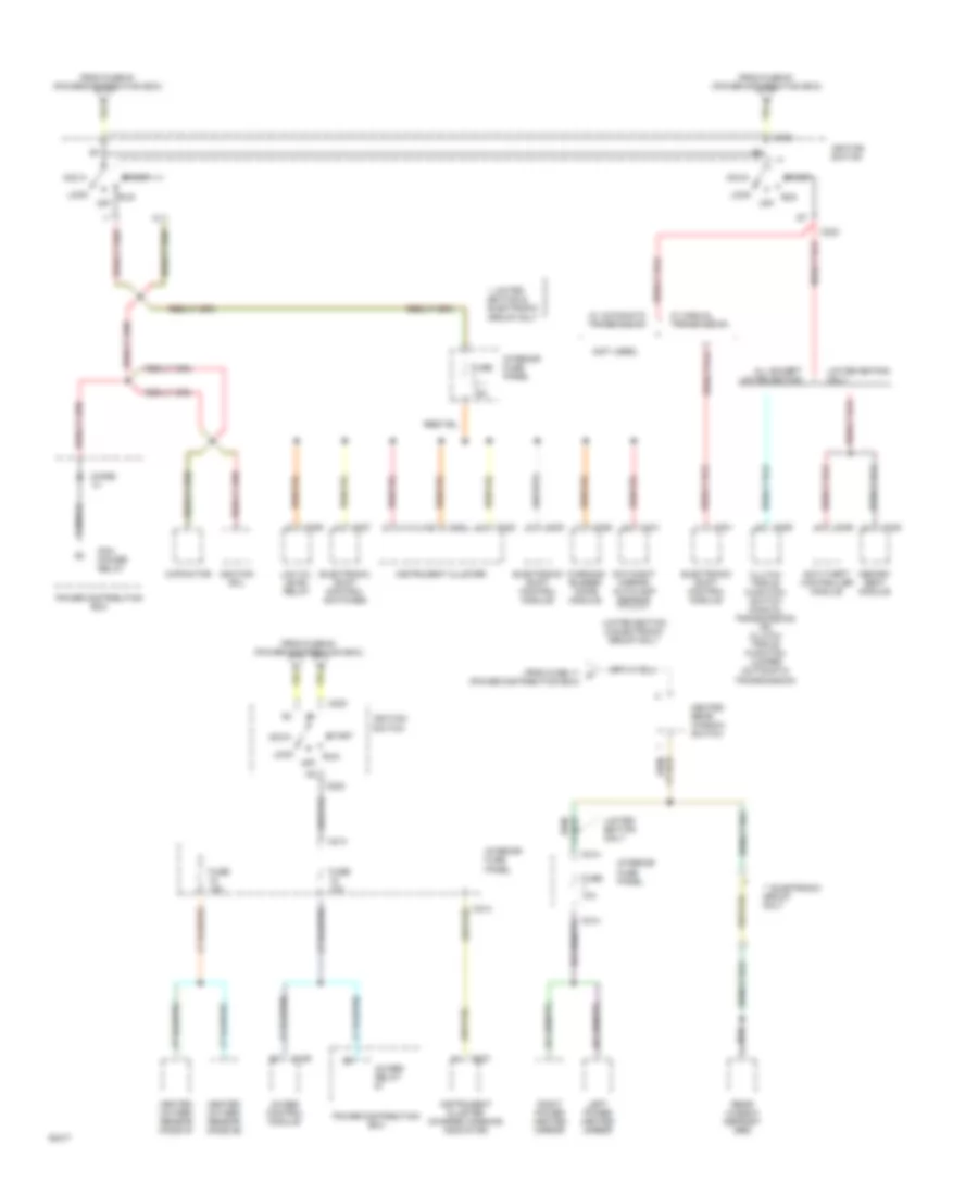
Power Distribution Wiring Diagram (4 of 5) for Ford Explorer 1994
List of elements for Power Distribution Wiring Diagram (4 of 5) for Ford Explorer 1994:
- (not used)
- 2-door only
- 4.5a
- Acc
- All except limited edition & electronic group
- All models
- Am/fm stereo w/ cassette
- Anti-theft controller module
- C.b. 6a
- C214
- C216
- C218
- C223
- C228
- C234
- C249
- C255
- C337
- C338
- C501
- C508
- C601
- Circuit breaker 30a
- Circuit breaker 6a
- Cruise control amplifier
- From fuse #1 (power distribution box)
- Fuse 10a
- Fuse 15a
- Headlamp switch
- Ign
- Ignition switch
- In-line circuit breaker
- Interior fuse panel
- Interval windshield wiper (iww) governor
- Interval wiper/ washer switch
- Liftgate wiper motor
- Liftgate wiper/ washer switch
- Limited edition & electronic group only
- Lock
- Master window control switch
- Off
- One-touch module
- Passenger door lock/ window switch
- Red
- Remote keyless entry module
- Run
- Start
- W/o highline sound or premium sound
- Wiper motor
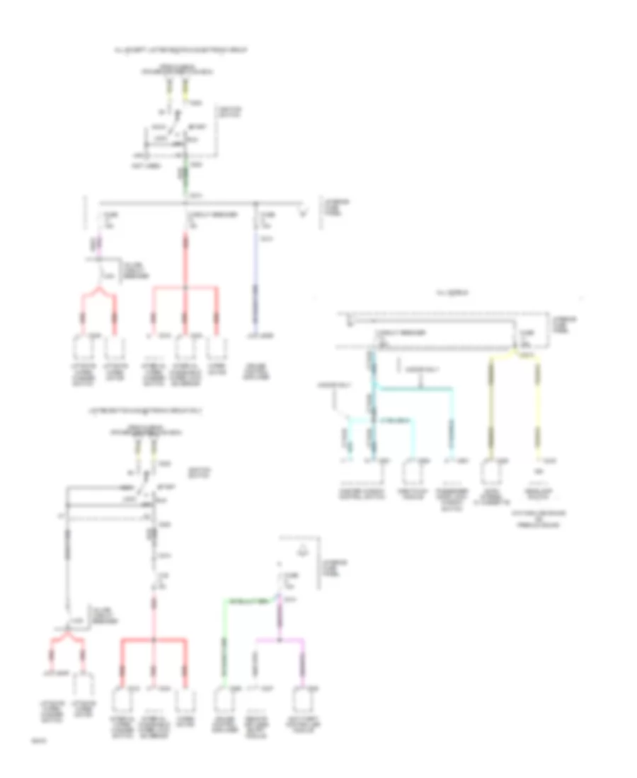
Power Distribution Wiring Diagram (5 of 5) for Ford Explorer 1994
List of elements for Power Distribution Wiring Diagram (5 of 5) for Ford Explorer 1994:
- Acc
- All except limited edition
- Backup lamp switch
- Blower motor relay
- C134
- C176
- C214
- C223
- C230
- C231
- C248
- C342
- Daytime running lamps (drl) module
- From fuse #1 (power distribution box)
- Fuse 10a
- Fuse 15a
- Heated rear window switch
- Heater- a/c control assembly
- Ignition switch
- Interior fuse panel
- Limited edition only
- Lock
- Off
- Overhead console
- Park/neutral position switch
- Power distribution box
- Run
- Start
- Turn signal flasher
- W/ automatic transmission
- W/ manual transmission
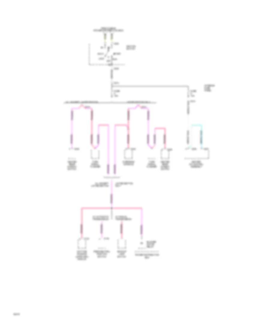
POWER DOOR LOCKS
Door Lock Wiring Diagram, 2 Door for Ford Explorer 1994
List of elements for Door Lock Wiring Diagram, 2 Door for Ford Explorer 1994:
- 30a
- Fuse 6
- G200 (left side of vehicle, behind kick panel)
- Hot at all times
- Left front door lock motor
- Liftgate lock motor
- Lock
- Master window control switch
- Passenger door lock/ window switch
- Power distribution box
- Right front door lock motor
- Unlock
Door Lock Wiring Diagram, 4 Door for Ford Explorer 1994
List of elements for Door Lock Wiring Diagram, 4 Door for Ford Explorer 1994:
- 30a
- Fuse 6
- G200 (left side of vehicle, behind kick panel)
- Hot at all times
- Left front door lock motor
- Left rear door lock motor
- Liftgate lock motor
- Lock
- Master window control switch
- Passenger door lock/ window switch
- Pnk/
- Power distribution box
- Power mirrors system
- Right front door lock motor
- Right rear door lock motor
- Unlock
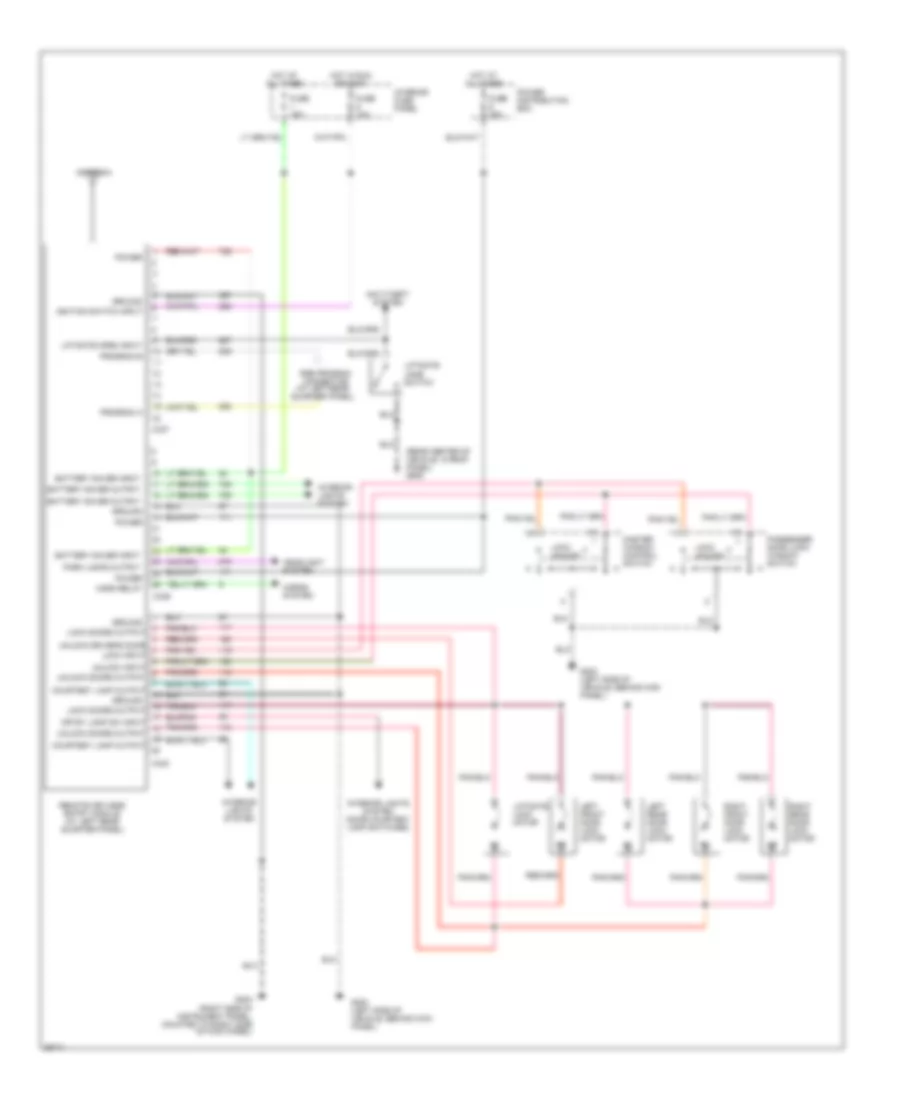
Keyless Entry Wiring Diagram for Ford Explorer 1994
List of elements for Keyless Entry Wiring Diagram for Ford Explorer 1994:
- (rear center of vehicle, in roof panel) g909
- (right side of instrument panel, mounted to right side of kick panel)
- Antenna
- Anti-theft system
- Battery saver input
- Battery saver output
- C337
- C339
- C340
- Courtesy lamp output
- Crtsy lamp sw input
- Fuse 10a
- Fuse 15a
- Fuse 30a
- G200 (left side of vehicle, behind kick panel)
- G203
- Ground
- Headlight system
- Horn relay
- Horns system
- Hot at all times
- Hot in run or accy
- Ignition switch input
- Interior fuse panel
- Interior lights system
- Interior lights system (door courtesy lamp switches)
- Left front door lock motor
- Left rear door lock motor
- Liftgate jamb switch
- Liftgate lock motor
- Liftgate open input
- Lock doors output
- Lock input
- Lock unlock
- Master window control switch
- Park lamps output
- Passenger door lock/ window switch
- Power
- Power distribution box
- Program a
- Program b
- Remote keyless entry module (at left rear quarter panel)
- Right front door lock motor
- Right rear door lock motor
- Rke program connector (at left rear quarter panel)
- Unlock doors output
- Unlock driver's door
- Unlock input
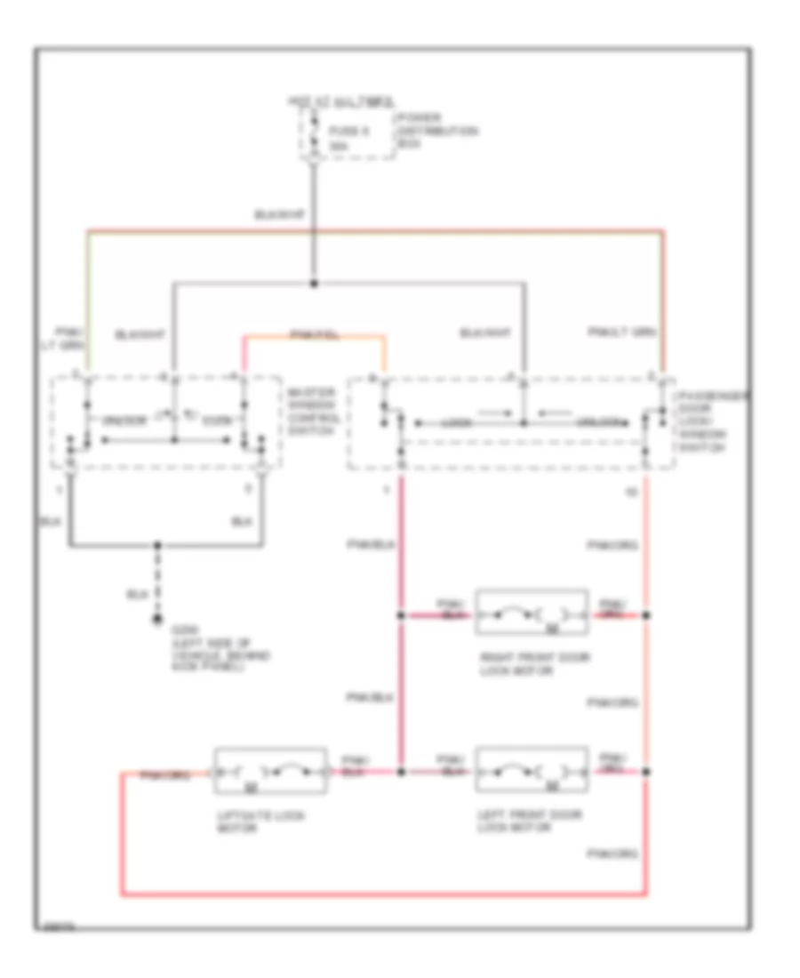
Power Door Locks Wiring Diagram, 2 Door for Ford Explorer 1994
List of elements for Power Door Locks Wiring Diagram, 2 Door for Ford Explorer 1994:
- 30a
- Fuse 6
- G200 (left side of vehicle, behind kick panel)
- Hot at all times
- Left front door lock motor
- Liftgate lock motor
- Lock
- Master window control switch
- Passenger door lock/ window switch
- Power distribution box
- Right front door lock motor
- Unlock
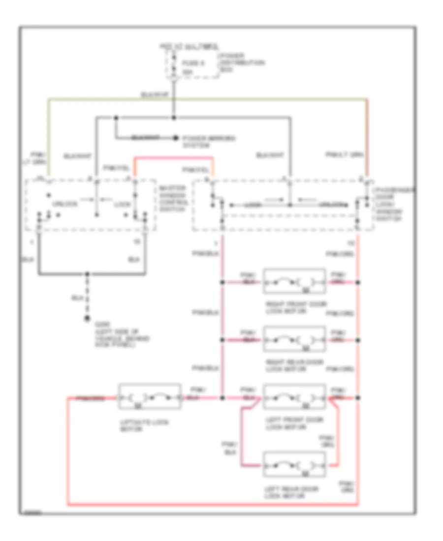
Power Door Locks Wiring Diagram, 4 Door for Ford Explorer 1994
List of elements for Power Door Locks Wiring Diagram, 4 Door for Ford Explorer 1994:
- 30a
- Fuse 6
- G200 (left side of vehicle, behind kick panel)
- Hot at all times
- Left front door lock motor
- Left rear door lock motor
- Liftgate lock motor
- Lock
- Master window control switch
- Passenger door lock/ window switch
- Pnk/
- Power distribution box
- Power mirrors system
- Right front door lock motor
- Right rear door lock motor
- Unlock
POWER MIRRORS
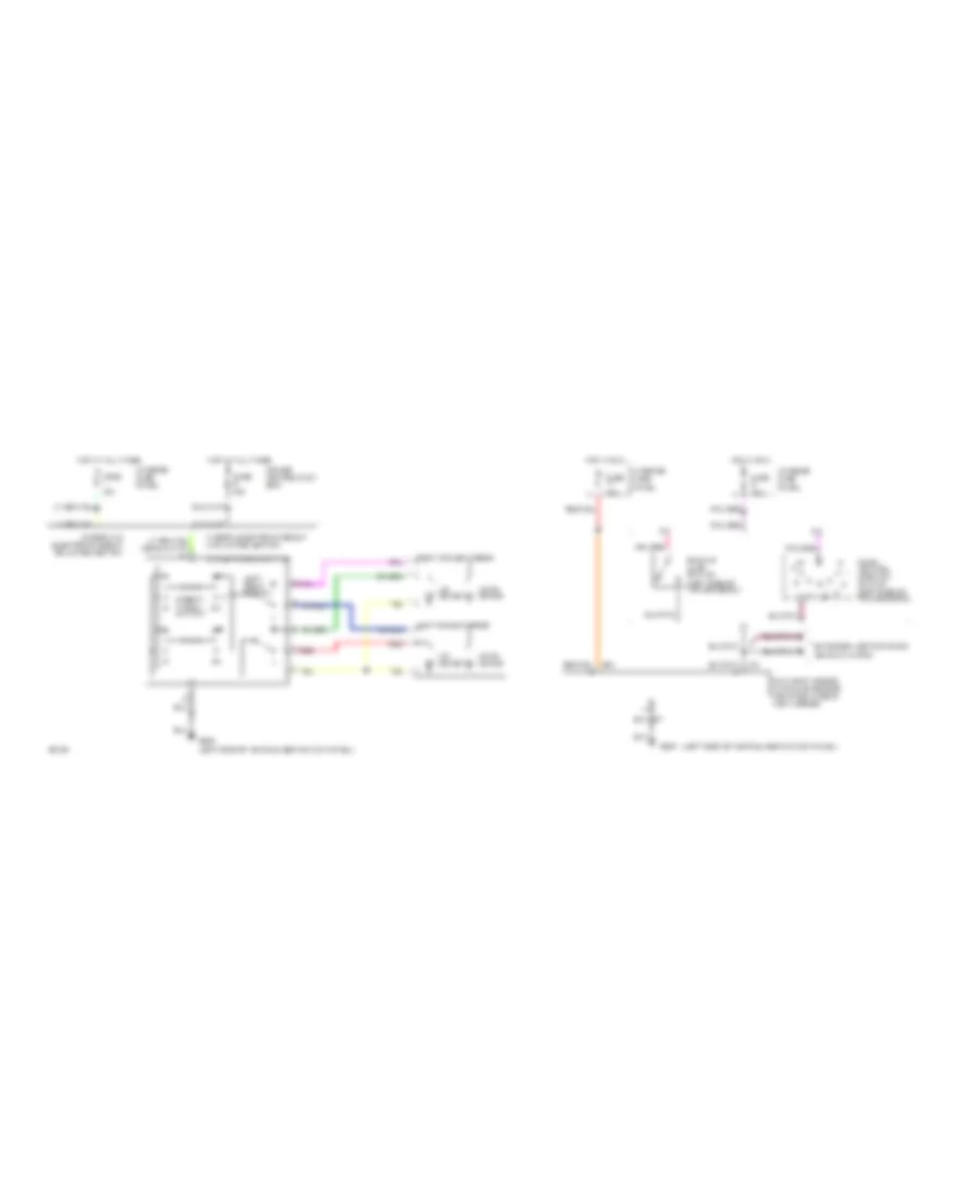
Power Mirror Wiring Diagram for Ford Explorer 1994
List of elements for Power Mirror Wiring Diagram for Ford Explorer 1994:
- (left side of vehicle, behind kick panel)
- 2 door w/o electronic group or limited edition
- 4 door, electronic group and limited edition
- A/t
- Backup lamp switch (left side of transmission)
- Day/night mirror autolamp sensor (mounted in rear view mirror)
- Direct- tional switch
- Exterior lights system (backup lamps)
- Fuse 15a
- Fuse 30a
- G200
- G200 (left side of vehicle, behind kick panel)
- Hot at all times
- Hot in run
- Interior fuse panel
- L/r motor
- Left power mirror
- Left/ right switch
- M/t
- Park/ neutral position switch (left side of transmission)
- Power distribution box
- Power mirror switch
- Red
- Right power mirror
- Up/dn motor
POWER SEATS
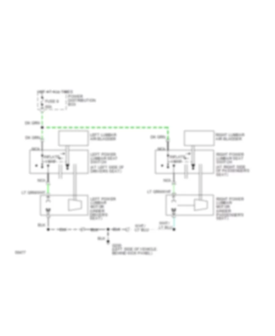
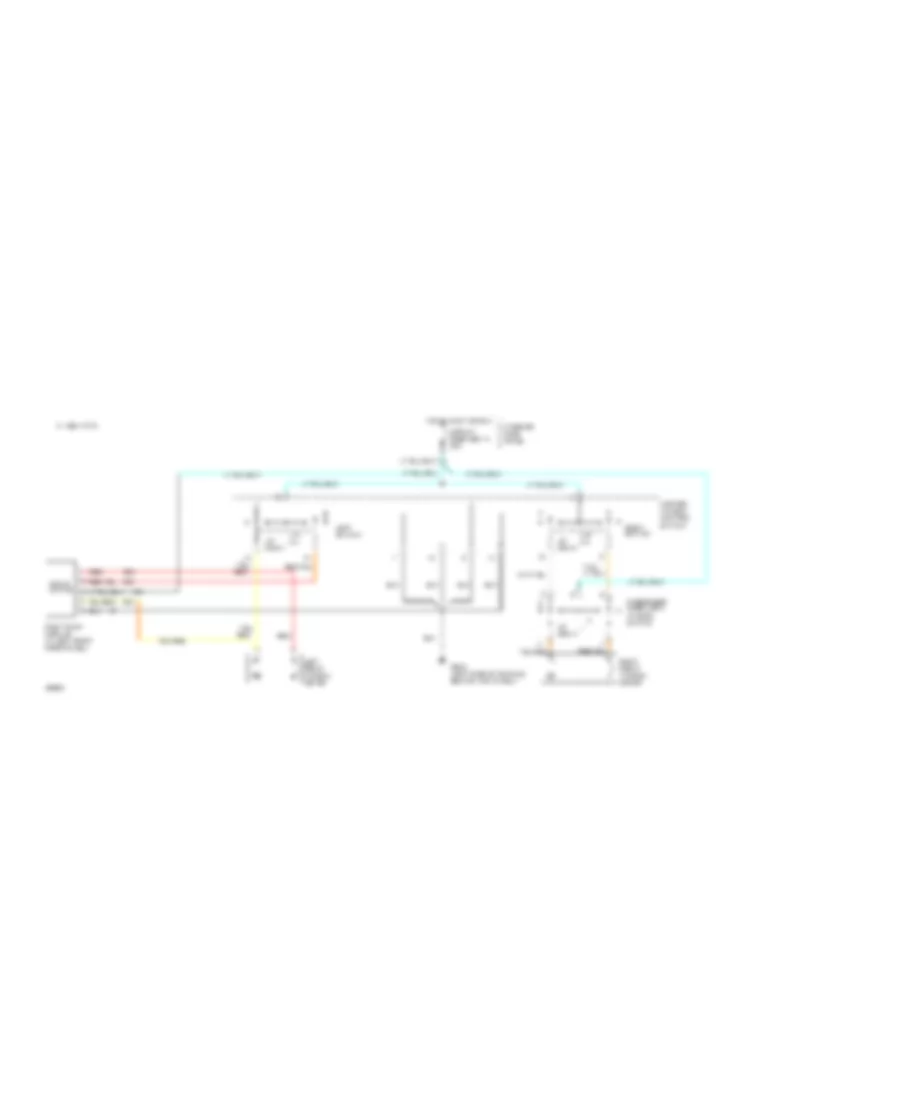
Lumbar Wiring Diagram, Limited Edition for Ford Explorer 1994
List of elements for Lumbar Wiring Diagram, Limited Edition for Ford Explorer 1994:
- (at left side of driver's seat)
- 60a
- Fuse 8
- G200 (left side of vehicle, behind kick panel)
- Hot at all times
- Inflate vent
- Left lumbar air bladder
- Left power lumbar motor (under driver's seat)
- Left power lumbar seat switch
- Nca
- Power distribution box
- Right lumbar air bladder
- Right power lumbar motor (under passenger's seat)
- Right power lumbar seat switch (at right side of passenger's seat)
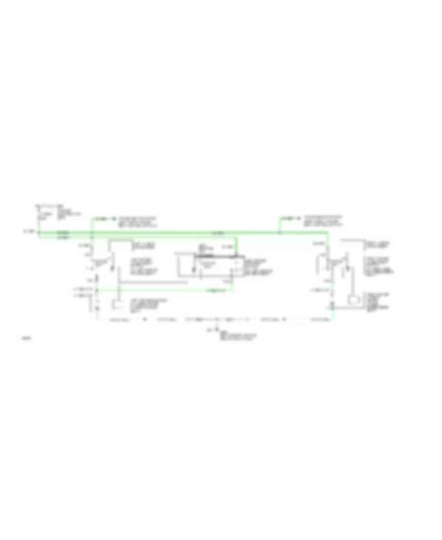
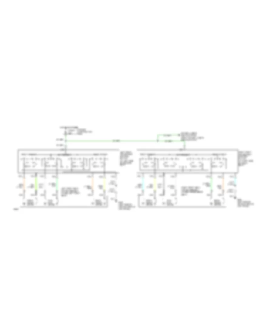
Lumbar/Bolster Wiring Diagram, Except Limited Edition Models for Ford Explorer 1994
List of elements for Lumbar/Bolster Wiring Diagram, Except Limited Edition Models for Ford Explorer 1994:
- (at left side of driver's seat)
- (right front power seat control switch)
- 60a
- Fuse 8
- G200 (left side of vehicle, behind kick panel)
- Hot at all times
- Inflate vent
- Left bolster air bladder
- Left lumbar air bladder
- Left power bolster switch
- Left power bolster & lumbar motor (under driver's
- Left power lumbar seat switch
- Nca
- Power distribution box
- Power seats system
- Power seats system (left front power seat control switch)
- Right lumbar air bladder
- Right power lumbar motor (under passenger's seat)
- Right power lumbar seat switch (at right side of passenger's seat)
- Seat)
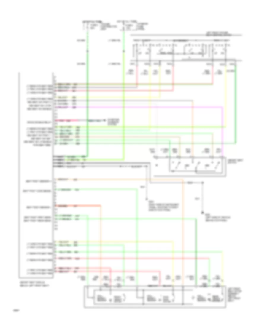
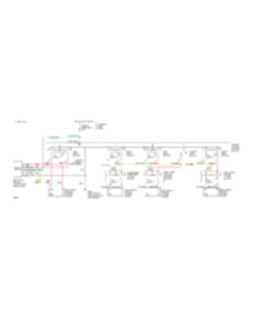
Memory Seat Wiring Diagram for Ford Explorer 1994
List of elements for Memory Seat Wiring Diagram for Ford Explorer 1994:
- 982
- (below left front seat)
- (left side of vehicle,
- (right side of instrument
- 15a
- 60a
- Behind kick panel)
- Crank enable relay
- Entire seat
- Front height motor
- Front of seat
- Fuse 8
- Fwd rwd
- Fwd/ rwd motor
- G200
- G203
- Hall effect sensor
- Hot at all times
- Interior fuse panel
- Left front power seat control switch
- Left front seat motor assembly (below left front seat)
- Lt frnt mtr seat reg
- Lt frnt mtr seat reg lt horz mtr seat reg
- Lt horz mtr seat reg
- Lt rear mtr seat reg
- Mem
- Mem seat sw enable
- Mem seat sw lp dr
- Mem seat sw lp enable
- Mem seat sw posit 1
- Mem seat sw posit 2
- Mem seat sw set
- Memory seat module
- Memory seat switch
- Nca
- Panel, mounted to right side of kick panel)
- Pnk
- Power distribution box
- Pwr seat feed
- Rear height motor
- Rear of seat
- Red
- Seat posit (frnt sens)
- Seat posit (horz sense)
- Seat posit (rear sens)
- Seat posit (sensor +)
- Seat posit (sensor -)
- Set
- Starting/ charging system
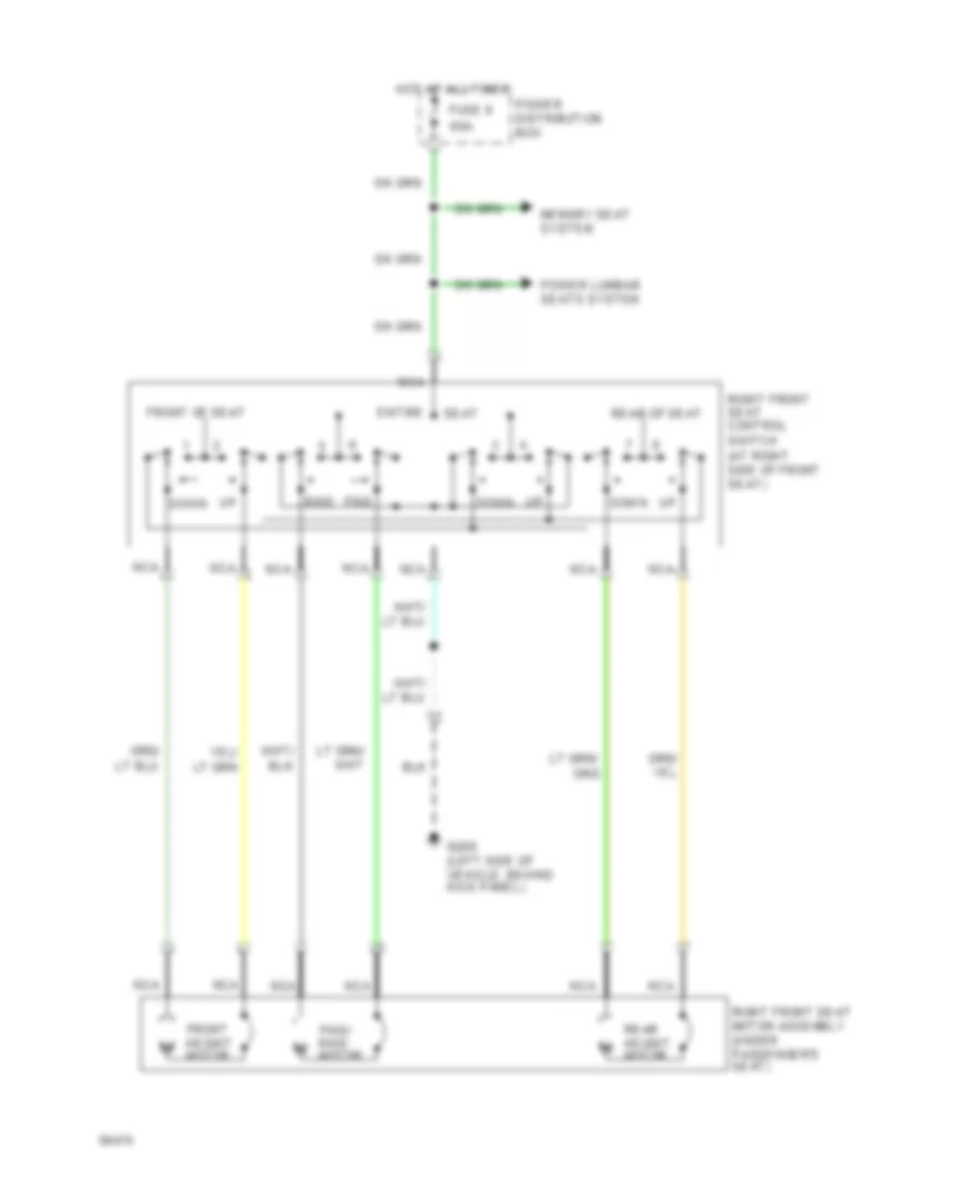
Power Seat Wiring Diagram, Except Limited Edition Models for Ford Explorer 1994
List of elements for Power Seat Wiring Diagram, Except Limited Edition Models for Ford Explorer 1994:
- (at left side of driver's seat)
- (at right side of front seat)
- 60a
- Down up
- Entire seat
- Front height motor
- Front of seat
- Fuse 8
- Fwd rwd
- Fwd/ rwd motor
- G200 (left side of vehicle, behind kick panel)
- Hot at all times
- Left front power seat control switch
- Left front seat motor assembly (under left front
- Nca
- Power distribution box
- Power lumbar seats system (right power lumbar seats switch)
- Rear height motor
- Rear of seat
- Right front power seat control switch
- Right front seat motor assembly (under passenger's
- Seat)
- Up down
Power Seat Wiring Diagram, Limited Edition for Ford Explorer 1994
List of elements for Power Seat Wiring Diagram, Limited Edition for Ford Explorer 1994:
- (at right side of front seat)
- 60a
- Entire
- Front height motor
- Front of seat
- Fuse 8
- Fwd rwd
- Fwd/ rwd motor
- G200 (left side of vehicle, behind kick panel)
- Hot at all times
- Memory seat system
- Nca
- Power distribution box
- Power lumbar seats system
- Rear height motor
- Rear of seat
- Right front seat control switch
- Right front seat motor assembly (under passenger's seat)
- Seat
- Up down
POWER WINDOWS
Power Window Wiring Diagram, 2 Door for Ford Explorer 1994
List of elements for Power Window Wiring Diagram, 2 Door for Ford Explorer 1994:
- 1994 vftc c
- Circuit breaker 14 30a
- G200 (left side of vehicle, behind kick panel)
- Hot in accy or run
- Interior fuse panel
- Left front window motor
- Left switch
- Master window control switch
- One touch module (in left front door panel)
- Passenger door lock/
- Red
- Right front window motor
- Right switch
- Solid state
- Tan/
- Up down
- Window switch
Power Window Wiring Diagram, 4 Door for Ford Explorer 1994
List of elements for Power Window Wiring Diagram, 4 Door for Ford Explorer 1994:
- (base) (ltd ed & elec model)
- 1994 vftc c
- Circuit breaker 14 30a
- G200 (left side of vehicle, behind kick panel)
- Hot in accy or run
- Interior fuse panel
- Left front power window motor
- Left front switch
- Left rear power window motor
- Left rear power window switch
- Left rear switch
- Master window control switch
- One touch module (in left front door panel)
- Passenger door lock/
- Red
- Right front power window motor
- Right front switch
- Right rear power window motor
- Right rear power window switch
- Right rear switch
- Solid state
- Tan/
- Tan/ red
- Tan/red
- Up down
- Window lock switch
- Window switch
RADIO
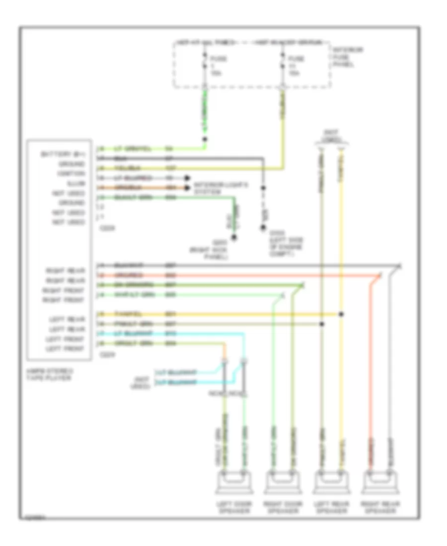
Base Radio for Ford Explorer 1994
List of elements for Base Radio for Ford Explorer 1994:
- (not used)
- Am/fm stereo tape player
- Battery (b+)
- C228
- C229
- Fuse 15a
- G100 (left side of engine compt)
- G203 (right kick panel)
- Ground
- Hot at all times
- Hot in accy or run
- Ignition
- Illum
- Interior fuse panel
- Interior lights system
- Left door speaker
- Left front
- Left rear
- Left rear speaker
- Nca
- Not used
- Right door speaker
- Right front
- Right rear
- Right rear speaker
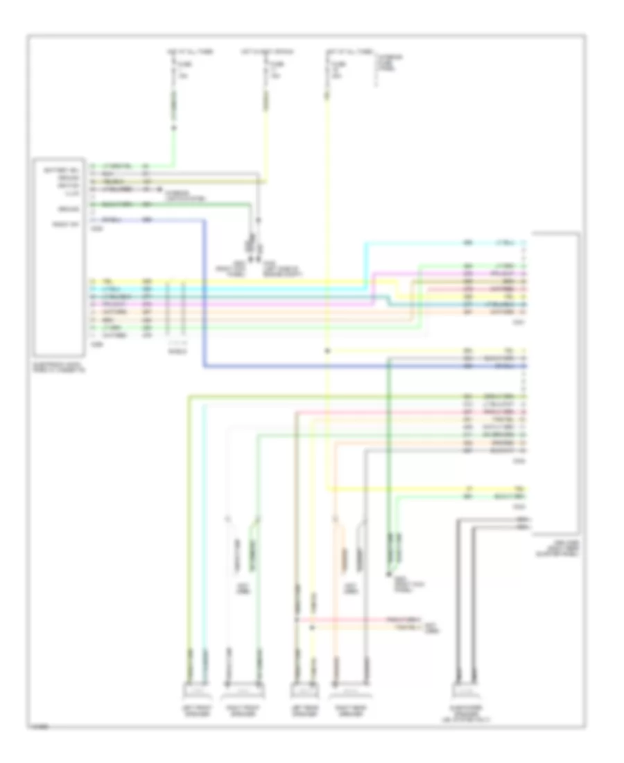
Premium Sound Radio Wiring Diagram for Ford Explorer 1994
List of elements for Premium Sound Radio Wiring Diagram for Ford Explorer 1994:
- (not used)
- Amplifier (right rear quarter panel)
- Battery (b+)
- C228
- C256
- C331
- C332
- C333
- Electronic am/fm radio w/ cassette
- Fuse 15a
- Fuse 20a
- G100 (left side of engine compt)
- G203 (right kick panel)
- Ground
- Hot at all times
- Hot in accy or run
- Ignition
- Illum
- Interior fuse panel
- Interior lights system
- Left front speaker
- Left rear speaker
- Nca
- Radio "on"
- Right front speaker
- Right rear speaker
- Shield
- Subwoofer speaker (jbl system only)
STARTING/CHARGING
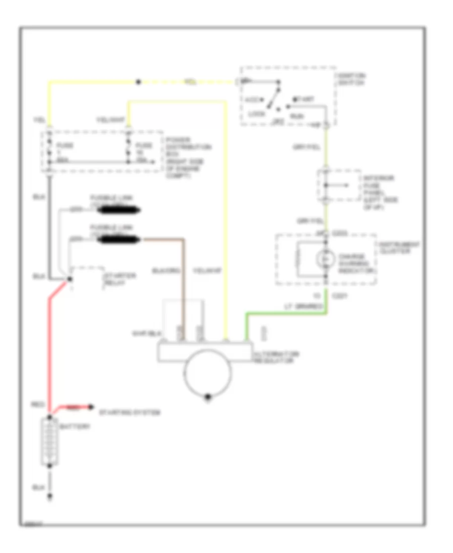
Charging Wiring Diagram for Ford Explorer 1994
List of elements for Charging Wiring Diagram for Ford Explorer 1994:
- Acc
- Battery
- C120
- C121 alternator/ regulator
- C122
- C221
- Charge warning indicator
- Fuse 15a
- Fuse 60a
- Ignition switch
- Instrument cluster
- Interior fuse panel (left side of i/p)
- Lock
- Off
- Power distribution box (right side of engine compt)
- Red
- Run
- Start
- Starter relay
- Starting system
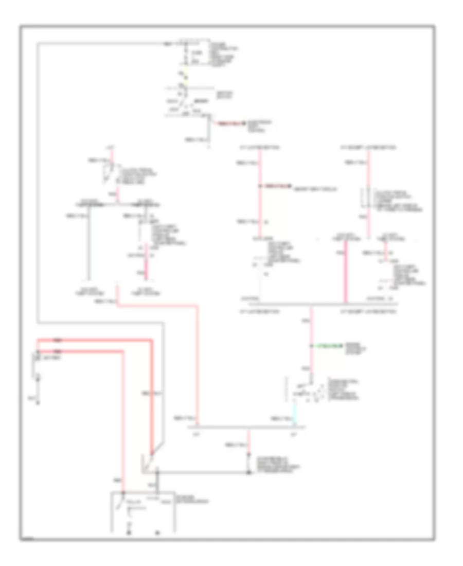
Starting Wiring Diagram for Ford Explorer 1994
List of elements for Starting Wiring Diagram for Ford Explorer 1994:
- (left side of transmission)
- A/t
- A/t (except limited edition)
- A/t (limited edition)
- Acc
- Anti-theft controller module (left rear quarter panel)
- Battery
- C336
- Clutch triple function switch (on clutch pedal arm)
- Clutch triple function switch jumper (behind left side of i/p, taped to harness)
- Electronic shift control
- Engine controls system
- Fuse 60a
- Hold
- Ignition switch
- Lock
- M/t
- Memory seat module
- Off
- Park/neutral position switch
- Pnk
- Power distribution box (right side of engine compt)
- Pull-in
- Red
- Run
- Start
- Starter motor/solenoid
- Starter relay (right front of engine compartment, at fender apron)
- W/ anti- theft system
- W/o anti- theft system
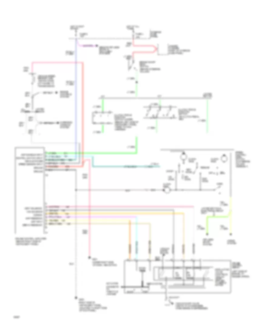
TRANSMISSION
4.0L
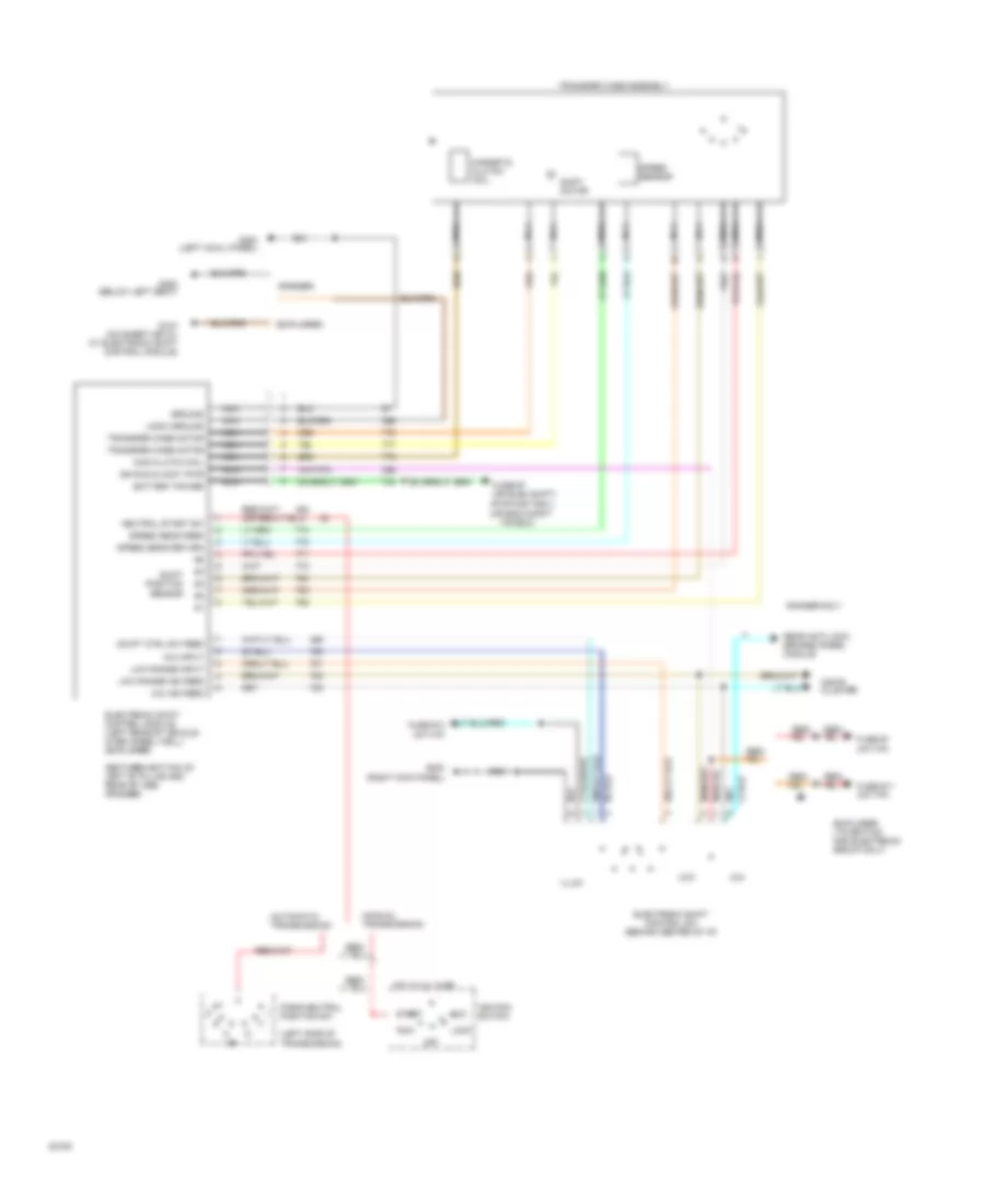
4.0L, Transfer Case Wiring Diagram for Ford Explorer 1994
List of elements for 4.0L, Transfer Case Wiring Diagram for Ford Explorer 1994:
- (automatic transmission)
- (between bottom of left "b" pillar and rear of cab) (ranger)
- (explorer ltd edition and electronic group only)
- (explorer)
- (left side of transmission)
- (manual transmission)
- (pwr dist box ) (or eng compt
- (ranger)
- 4x4
- 4x4 ind feed
- 4x4 input
- Acc
- Battery power
- Electronic shift control module (left rear of vehicle over wheel well) (explorer)
- Electronic shift control sw (behind center of i/p)
- F/r box)
- Fuse #13 (int f/p)
- Fuse #17 (int f/p)
- Fuse #7 (int f/p)
- Fuse #7 (or elec shift)
- G104 (on sheet metal at electronic shift control module)
- G200 (left cowl panel)
- G203 (right kick panel)
- G300 (below left seat)
- Ground
- Hot at all times
- Ign run & accy pwr
- Ignition switch
- Illum
- Instr cluster
- Lock
- Logic ground
- Low
- Low range ind feed
- Low range input
- Mag clutch coil
- Magnetic clutch coil
- Nca
- Neutral start sw
- Off
- Park/neutral position sw
- Ranger only
- Rear anti-lock brakes (rabs) module
- Red/
- Run
- Sensor
- Shift motor
- Shift position
- Speed sens feed
- Speed sens return
- Speed sensor
- Start
- Swift ctrl sw feed
- Transfer case assembly
- Transfer case motor
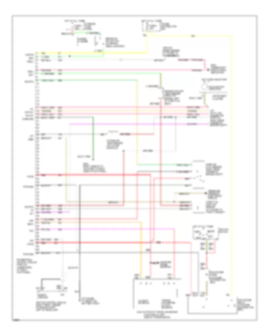
4.0L, Transmission Wiring Diagram for Ford Explorer 1994
List of elements for 4.0L, Transmission Wiring Diagram for Ford Explorer 1994:
- (attached to throttle body)
- (in power distribution box)
- (mounted on left side of transmission)
- (right rear corner of engine compt)
- (under dash, at right kick panel)
- 15a
- 3-4 shift solenoid
- 30a
- A4ld automatic trans. solenoids
- Accy
- Boo
- Brake on/ off switch (on brake pedal support)
- Canister purge solenoid
- Case gnd
- Data(+)
- Data(-)
- Ect
- Engine coolant temp sensor (front of engine, left of throttle body)
- Fuse 4
- G203 (right side of i/p, mounted to right side of kick panel)
- G203 (under right side of dash, above pcm)
- Ground
- Hazard flasher
- Hot at all times
- Hot in run and start
- Iat
- Ignition control module (right front corner of engine compt, left of headlamp)
- Ignition switch
- Instrument cluster
- Intake air temp sensor (on intake manifold)
- Interior fuse panel
- Kapwr
- Lock
- Maf
- Malfunction indicator
- Mass air flow sensor (right rear corner of engine compt)
- Mil
- Off
- Pcm power diode
- Pcm power relay (in power distribution box)
- Pip
- Power distribution box
- Powertrain control module (partial)
- Pressure feedback electronic module
- Pwr gnd
- Red
- Run
- Shield
- Sig rtn
- Ss3-4
- Start
- Sti
- Tcc
- Throttle position sensor
- Torque converter clutch solenoid
- Vehicle speed sensor attached to transmission)
- Vip data link connector (partial)
- Vpwr
- Vref
- Vss(+)
- Vss(-)
WARNING SYSTEMS
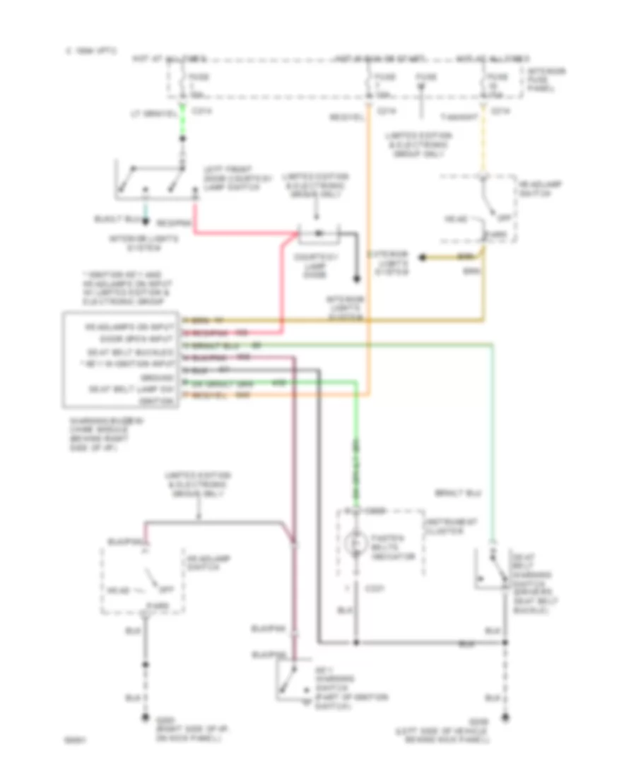
Warning System Wiring Diagrams for Ford Explorer 1994
List of elements for Warning System Wiring Diagrams for Ford Explorer 1994:
- * ignition key and headlamps on input w/ limited edition & electronic group
- * key in ignition input
- 1994 vftc c
- C214
- C221
- C222
- Courtesy lamp diode
- Door open input
- Exterior lights system
- Fasten belts indicator
- Fuse
- Fuse 15a
- G200 (left side of vehicle benind kick panel)
- G203 (right side of i/p, on kick panel)
- Ground
- Head
- Headlamp switch
- Headlamps on input
- Hot at all times
- Hot in run or start
- Ignition
- Instrument cluster
- Interior fuse panel
- Interior lights system
- Key warning switch (part of ignition switch)
- Left front door courtesy lamp switch
- Limited edition & electronic group only
- Off
- Park
- Red/pnk
- Seat belt buckled
- Seat belt lamp sw
- Seat belt warning switch (driver's seat belt buckle)
- Warning buzzer/ chime module (behind right side of i/p)
WIPER/WASHER
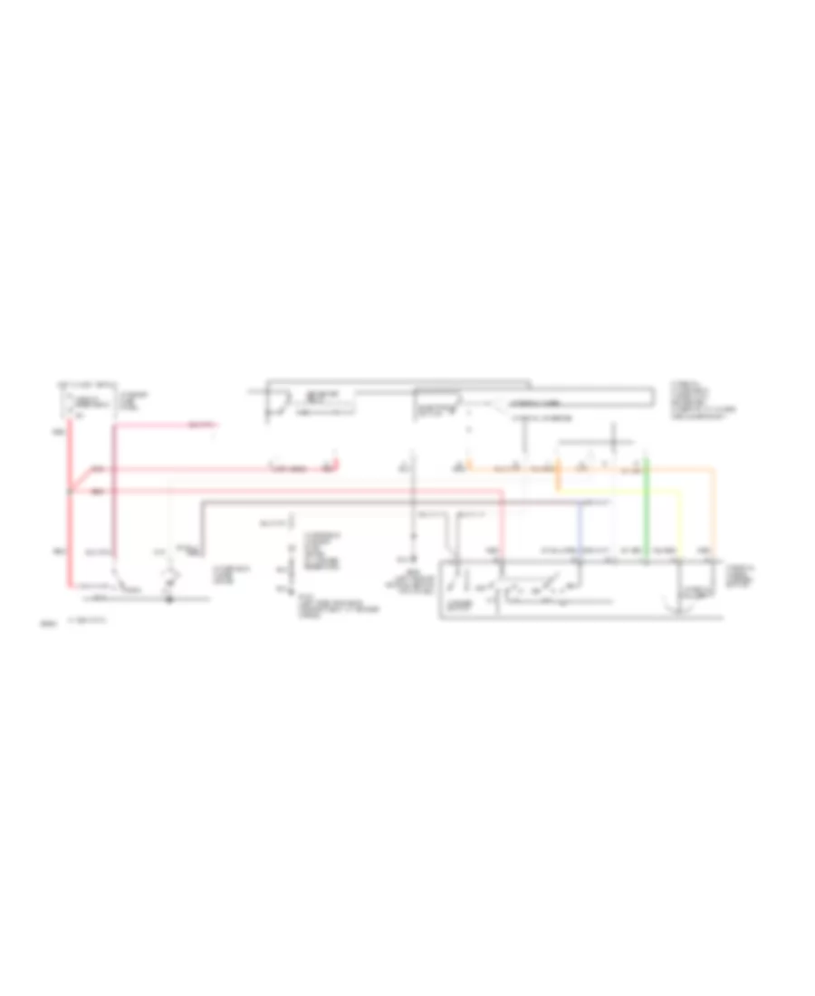
Front Wiper/Washer Wiring Diagram for Ford Explorer 1994
List of elements for Front Wiper/Washer Wiring Diagram for Ford Explorer 1994:
- (left side of vehicle, behind kick panel)
- (not used)
- 1994 vftc c
- Circuit breaker 2
- Electronic switch
- G104 (left side of engine compartment, at fender apron)
- G200
- Governor relay
- Hot in accy or run
- Int
- Interior fuse panel
- Interval adjust
- Interval override
- Interval timer
- Interval windshield wiper (iww) governor) (under i/p, at 4wabs module bracket)
- Interval wiper/ washer switch
- Off
- Park
- Red
- Run
- Washer switch
- Windshield washer pump motor (in washer reservoir)
- Windshield wiper motor
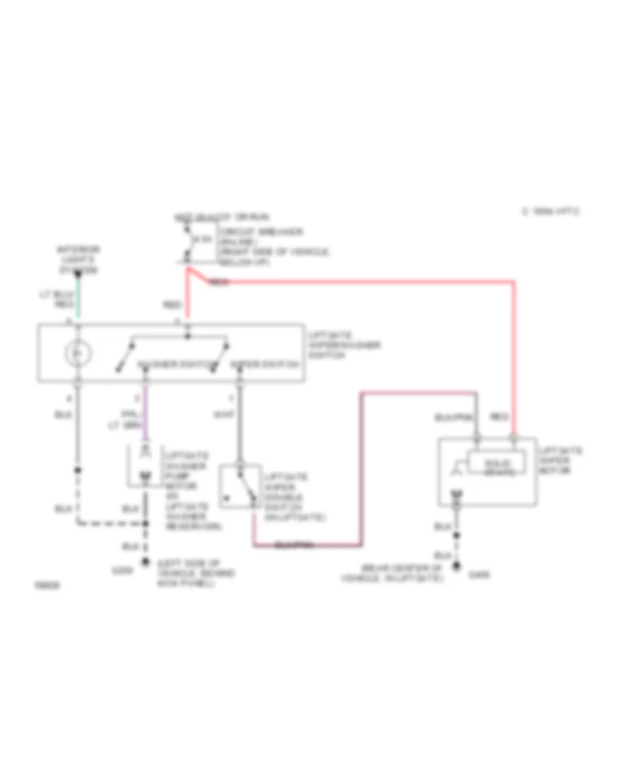
Rear Wiper/Washer Wiring Diagram for Ford Explorer 1994
List of elements for Rear Wiper/Washer Wiring Diagram for Ford Explorer 1994:
- (left side of vehicle, behind kick panel)
- (rear center of vehicle, in liftgate)
- 1994 vftc c
- 4.5a
- Circuit breaker (in-line) (right side of vehicle, below i/p)
- G200
- G406
- Hot in accy or run
- Interior lights system
- Liftgate washer pump motor (in liftgate washer reservoir)
- Liftgate wiper disable switch (in liftgate)
- Liftgate wiper motor
- Liftgate wiper/washer switch
- Red
- Solid state
- Washer switch
- Wiper switch

 Čeština
 Dansk
Dansk Deutsch
 Ελληνικά
 English
 English
 Suomi
Suomi Français
 Français
 עברית
עברית Hrvatski
 Magyar
 Italiano
 日本語
日本語 한국어
한국어 Nederlands
 Polski
 Português
 Português
 Română
 Русский
 Slovenčina
 Slovenščina
 Svenska
 Türkçe
 中文 (中国)