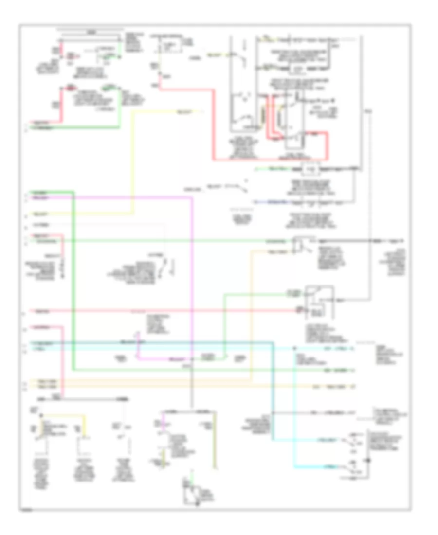
AIR CONDITIONING
5.8L
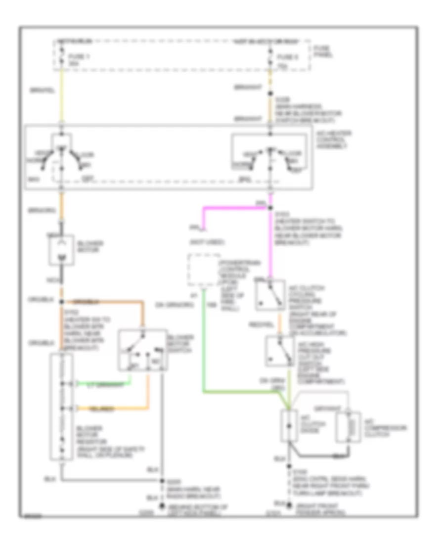
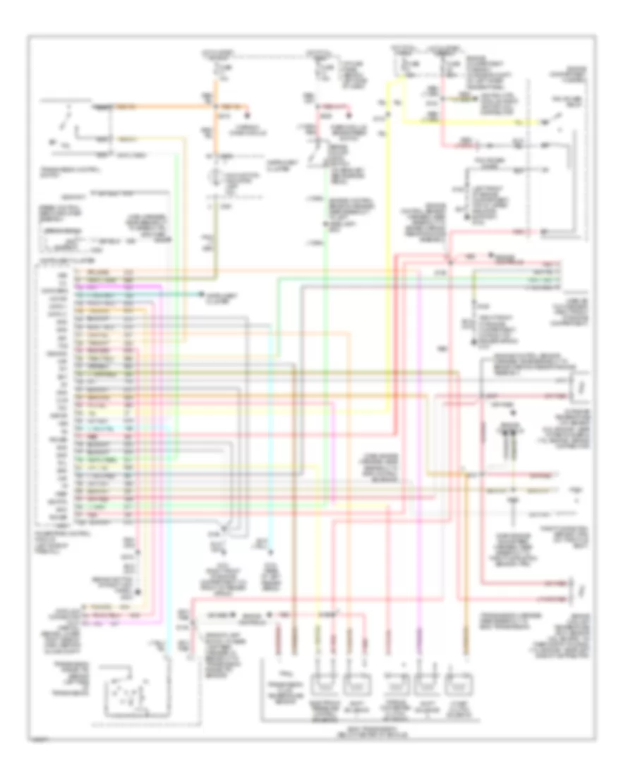
5.8L, A/C Wiring Diagram for Ford F-Super Duty 1997
 https://portal-diagnostov.com/license.html
Automotive Electricians Portal FZCO
Automotive Electricians Portal FZCO
https://portal-diagnostov.com/license.html
https://portal-diagnostov.com/license.html
Automotive Electricians Portal FZCO
Automotive Electricians Portal FZCO
List of elements for 5.8L, A/C Wiring Diagram for Ford F-Super Duty 1997:
- (behind bottom of left kick panel)
- (heater switch to blower motor harn, near blower motor breakout)
- (left front of engine compartment)
- 15a
- 49 states or super duty only
- A/c clutch cycling pressure switch (right rear of engine compartment on accumulator)
- A/c clutch diode
- A/c clutch field coil
- A/c high pressure cut out switch (right side engine compartment)
- A/c-heater control assembly
- Blower motor
- Blower motor resistor (near blower motor)
- Blower motor switch
- Calif except super duty only
- Def
- Floor
- Fuse 1 30a
- Fuse 6
- Fuse panel
- G108
- G200
- Hot in accy or run
- Hot in run
- Max
- Mix
- Norm
- Off
- Power- train control module (pcm) (on right side of engine compartment)
- S102 (eng cntrl sens harn, near brake warning resistor/ diode assembly breakout)
- S152 (heater sw to blower mtr harn, near blower mtr breakout)
- S153
- S205 (main harn, near radio breakout)
- S229 (main harness, near blower motor switch breakout)
- Vent
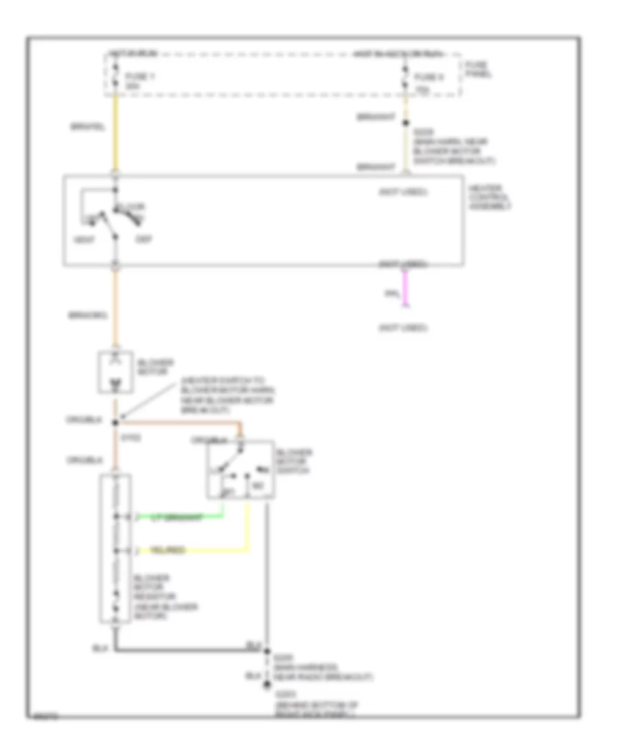
Heater Wiring Diagram for Ford F-Super Duty 1997
List of elements for Heater Wiring Diagram for Ford F-Super Duty 1997:
- (heater switch to blower motor harn, near blower motor breakout)
- (not used)
- 15a
- Blower motor
- Blower motor resistor (near blower motor)
- Blower motor switch
- Def
- Floor
- Fuse 1 30a
- Fuse 6
- Fuse panel
- G203 (behind bottom of right kick panel)
- Heater control assembly
- Hot in accy or run
- Hot in run
- Mix
- Off
- S152
- S205 (main harness, near radio breakout)
- S229 (main harn, near blower motor switch breakout)
- Vent
7.3L
7.3L DI Turbo Diesel, A/C Wiring Diagram for Ford F-Super Duty 1997
List of elements for 7.3L DI Turbo Diesel, A/C Wiring Diagram for Ford F-Super Duty 1997:
- (behind bottom of left kick panel)
- (not used)
- (right front fender apron)
- 15a
- A/c clutch cycling pressure switch (right rear of engine compartment on accumulator)
- A/c clutch diode
- A/c compressor clutch
- A/c high pressure cut out switch (left side engine compartment)
- A/c-heater control assembly
- Blower motor
- Blower motor resistor (right side of safety wall, on plenum)
- Blower motor switch
- Def
- Floor
- Fuse 1 30a
- Fuse 6
- Fuse panel
- G101
- G200
- Hot in accy or run
- Hot in run
- Max
- Mix
- Nca
- Norm
- Off
- Powertrain control module (pcm) (left side of fire- wall)
- S100 (eng cntrl sens harn, near right front park/ turn lamp breakout)
- S152 (heater sw to blower mtr harn, near blower mtr breakout)
- S153 (heater switch to blower motor harn, near blower motor breakout)
- S205 (main harn, near radio breakout)
- S229 (main harness, near blower motor switch breakout)
- Vent
Heater Wiring Diagram for Ford F-Super Duty 1997
List of elements for Heater Wiring Diagram for Ford F-Super Duty 1997:
- (heater switch to blower motor harn, near blower motor breakout)
- (not used)
- 15a
- Blower motor
- Blower motor resistor (near blower motor)
- Blower motor switch
- Def
- Floor
- Fuse 1 30a
- Fuse 6
- Fuse panel
- G203 (behind bottom of right kick panel)
- Heater control assembly
- Hot in accy or run
- Hot in run
- Mix
- Off
- S152
- S205 (main harness, near radio breakout)
- S229 (main harn, near blower motor switch breakout)
- Vent
7.5L
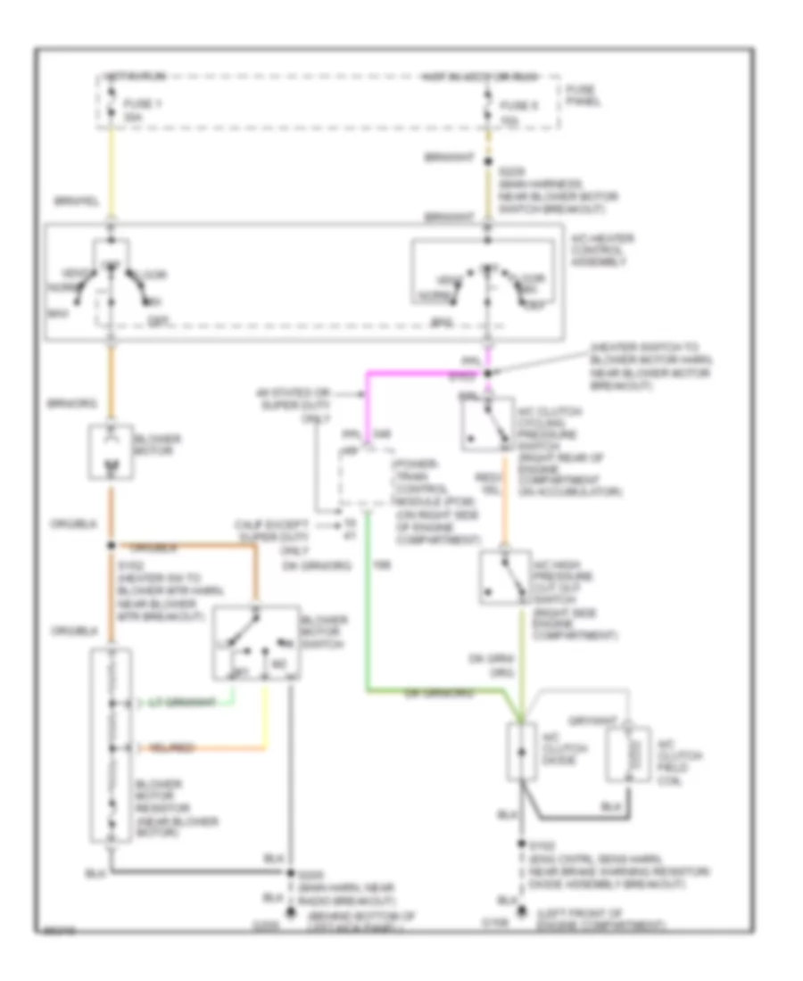
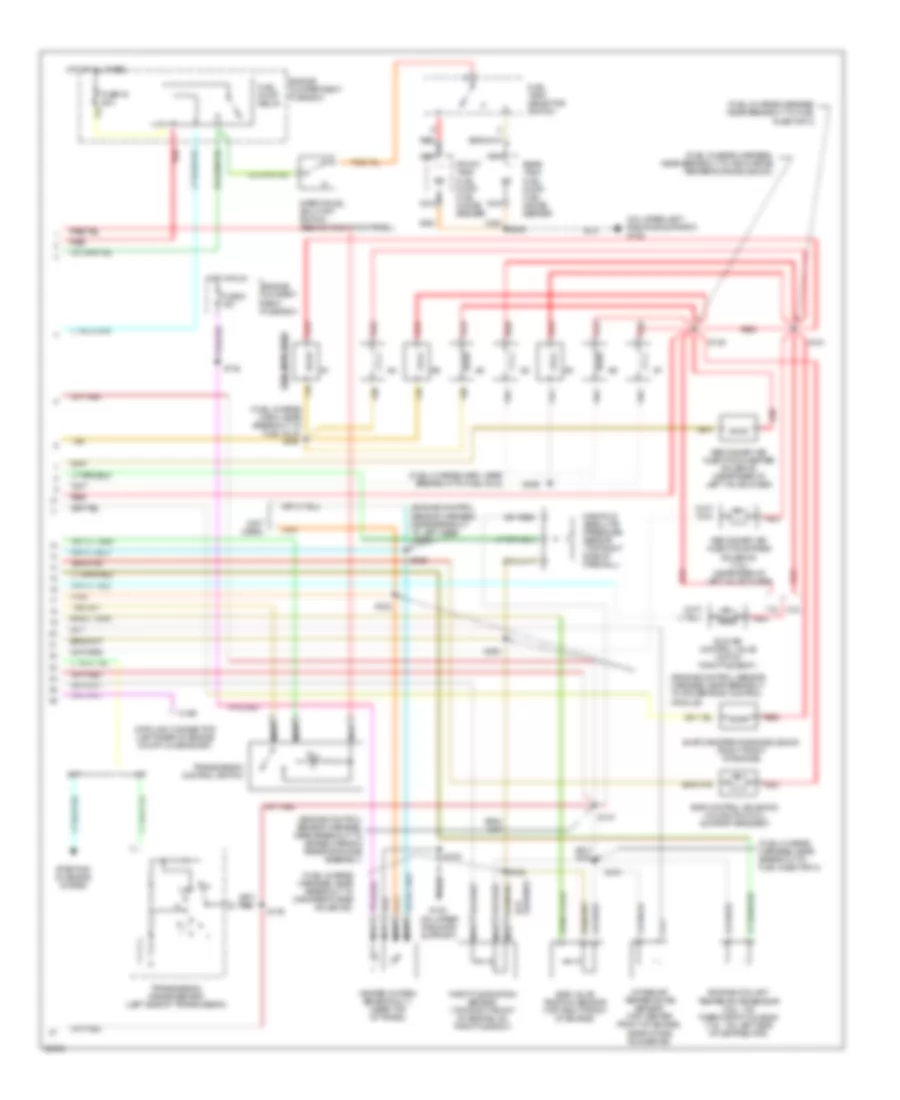
7.5L, A/C Wiring Diagram for Ford F-Super Duty 1997
List of elements for 7.5L, A/C Wiring Diagram for Ford F-Super Duty 1997:
- (behind bottom of left kick panel)
- (heater switch to blower motor harn, near blower motor breakout)
- (left front of engine compartment)
- 15a
- 49 states or super duty only
- A/c clutch cycling pressure switch (right rear of engine compartment on accumulator)
- A/c clutch diode
- A/c clutch field coil
- A/c high pressure cut out switch (right side engine compartment)
- A/c-heater control assembly
- Blower motor
- Blower motor resistor (near blower motor)
- Blower motor switch
- Calif except super duty only
- Def
- Floor
- Fuse 1 30a
- Fuse 6
- Fuse panel
- G108
- G200
- Hot in accy or run
- Hot in run
- Max
- Mix
- Norm
- Off
- Power- train control module (pcm) (on right side of engine compartment)
- S102 (eng cntrl sens harn, near brake warning resistor/ diode assembly breakout)
- S152 (heater sw to blower mtr harn, near blower mtr breakout)
- S153
- S205 (main harn, near radio breakout)
- S229 (main harness, near blower motor switch breakout)
- Vent
Heater Wiring Diagram for Ford F-Super Duty 1997
List of elements for Heater Wiring Diagram for Ford F-Super Duty 1997:
- (heater switch to blower motor harn, near blower motor breakout)
- (not used)
- 15a
- Blower motor
- Blower motor resistor (near blower motor)
- Blower motor switch
- Def
- Floor
- Fuse 1 30a
- Fuse 6
- Fuse panel
- G203 (behind bottom of right kick panel)
- Heater control assembly
- Hot in accy or run
- Hot in run
- Mix
- Off
- S152
- S205 (main harness, near radio breakout)
- S229 (main harn, near blower motor switch breakout)
- Vent
ANTI-LOCK BRAKES
Anti-lock Brake Wiring Diagrams for Ford F-Super Duty 1997
List of elements for Anti-lock Brake Wiring Diagrams for Ford F-Super Duty 1997:
- (main harn, left rear of engine compt)
- (rear lamp harn, near breakout to output shaft speed sensor) s429
- (w/o airbag) (w/ airbag)
- 4x4 input sig
- Acc
- Anti-lock brake ind
- Boo sw input
- Brake fluid level switch (on brake fluid reservoir)
- Brake fluid lvl sens (lo)
- Brake on/off (boo) switch (on bracket above brake pedal)
- Diag test/keep alive input
- Diff spd sens (hi)
- Diff spd sens (lo)
- Dump sol output
- Dump solenoid
- Fuse 13 15a
- Fuse 15 20a
- Fuse 17 10a
- Fuse panel
- G101 (right front of engine compartment, front of fender apron)
- G108 (left front of engine compartment, on upper radiator support)
- G200 (behind bottom of left kick panel)
- G203 (behind bottom of right kick panel)
- Ground
- Hot at all times
- Hot in run
- Hot in start or run
- Ignition switch
- Instrument cluster
- Instrument cluster system
- Iso sol output
- Isolation solenoid
- Lock
- Nca
- Off
- Power input
- Programmable speedometer/ odometer module
- Rabs data link connector (all gasoline: left rear of engine compartment) (7.3l diesel: behind lower center of dash)
- Rabs valve assembly (on frame rail, near front of transmission)
- Rear anti-lock brake (rabs) module (behind glove box)
- Rear axle sensor
- Red/pnk
- Run
- S102
- S202
- S215
- S216 s258
- S220
- S228 (main harn, in breakout to rabs module)
- S236
- S240
- S247 (main harn, left rear of engine compt)
- S248
- S428 (rear lamp harn, near breakout to output shaft speed sensor)
- Start
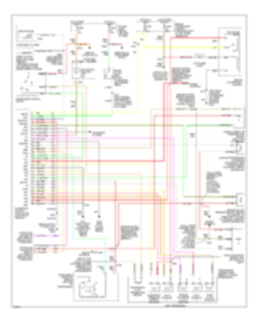
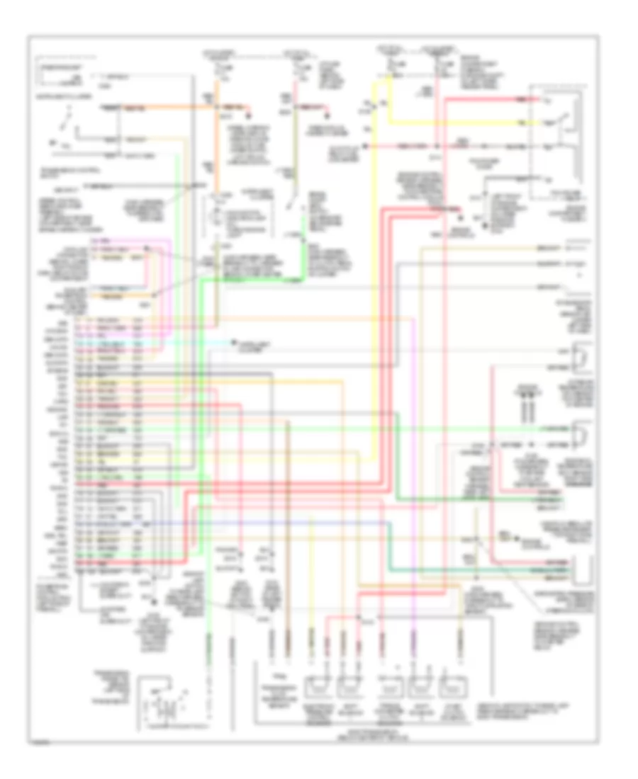
- Transmissions system
- Valve reset switch
- Vlv reset input
- Warn lp output
COMPUTER DATA LINES
5.8L
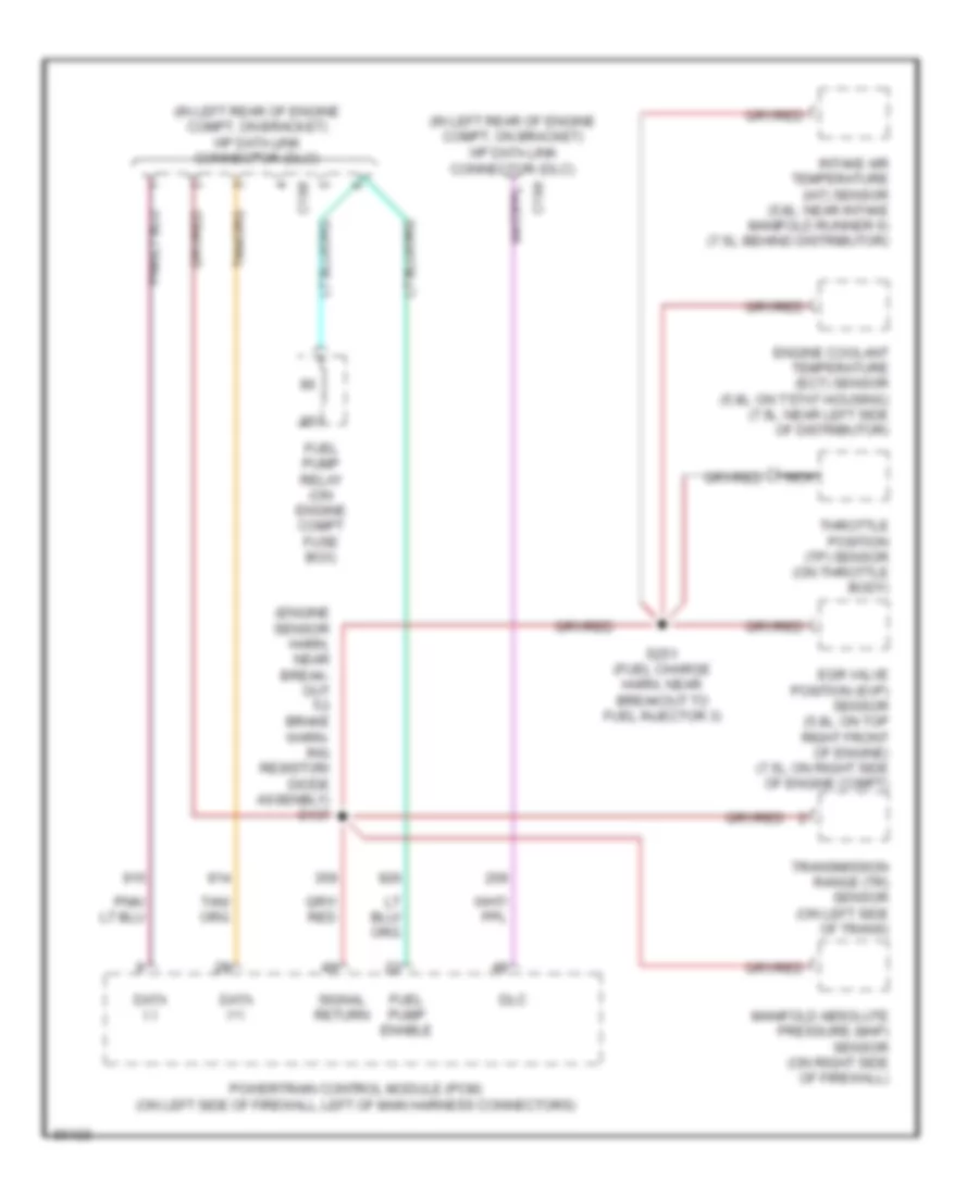
5.8L, Computer Data Lines, 49 States Or Super Duty for Ford F-Super Duty 1997
List of elements for 5.8L, Computer Data Lines, 49 States Or Super Duty for Ford F-Super Duty 1997:
- (engine sensor harn, near break- out to brake warn- ing resistor/ diode assenbly) s137
- (in left rear of engine compt, on bracket) vip data link connector (dlc)
- C198
- C199
- Data (+)
- Data (-)
- Dlc
- Egr valve position (evp) sensor (5.8l: on top right front of engine) (7.5l: on right side of engine compt)
- Engine coolant temperature (ect) sensor (5.8l: on t'stat housing) (7.5l: near left side of distributor)
- Fuel pump enable
- Fuel pump relay (on engine compt fuse box)
- Intake air temperature (iat) sensor (5.8l: near intake manifold runner 6) (7.5l: behind distributor)
- Manifold absolute pressure (map) sensor (on right side of firewall)
- Nca
- Powertrain control module (pcm) (on left side of firewall, left of main harness connectors)
- S251 (fuel charge harn, near breakout to fuel injector 3)
- Signal return
- Throttle position (tp) sensor (on throttle body)
- Transmission range (tr) sensor (on left side of trans)
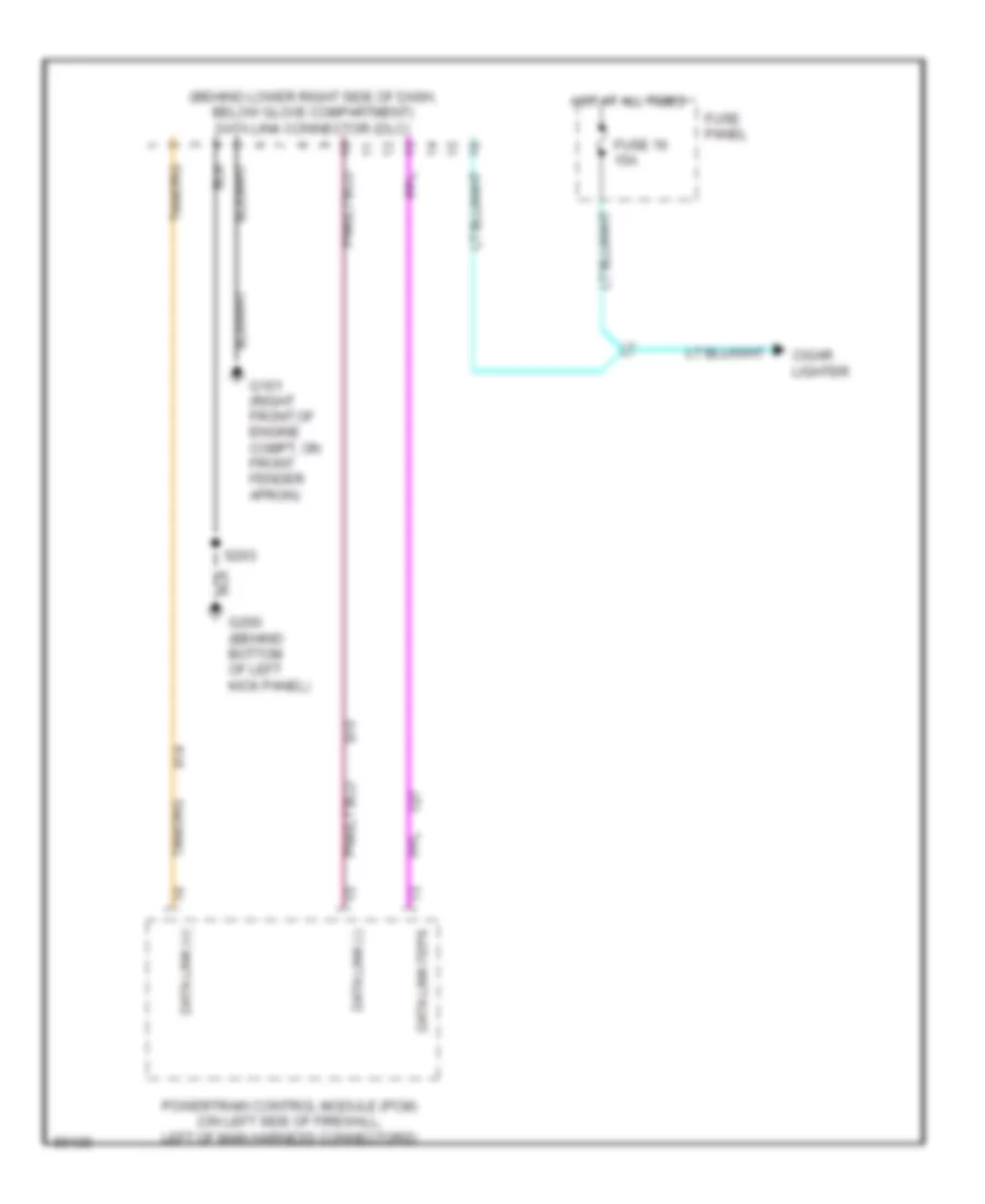
5.8L, Computer Data Lines, California Except Super Duty for Ford F-Super Duty 1997
List of elements for 5.8L, Computer Data Lines, California Except Super Duty for Ford F-Super Duty 1997:
- (behind lower right side of dash, below glove compartment) data link connector (dlc)
- Cigar lighter
- Data link (+)
- Data link (-)
- Data link feps
- Fuse 16 15a
- Fuse panel
- G101 (right front of engine compt, on front fender apron)
- G200 (behind bottom of left kick panel)
- Hot at all times
- Powertrain control module (pcm) (on left side of firewall, left of main harness connectors)
- S203
7.3L
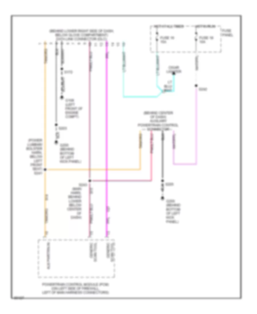
7.3L DI Turbo Diesel, Computer Data Lines for Ford F-Super Duty 1997
List of elements for 7.3L DI Turbo Diesel, Computer Data Lines for Ford F-Super Duty 1997:
- (behind center of dash) auxiliary powertrain control connector
- (behind lower right side of dash, below glove compartment) data link connector (dlc)
- (main harn, behind lower below center of dash)
- (power lumbar/ bolster harn, below left front seat) s241
- Aux pwrtrn in
- Cigar lighter
- Fuse 16 15a
- Fuse 18 10a
- Fuse panel
- G108 (left front of engine compt)
- G200 (behind bottom of left kick panel)
- Generic scan tool
- Hot at all times
- Hot in run
- Powertrain control module (pcm) (on left side of firewall, left of main harness connectors)
- S172
- S203
- S205
- S242
- S243
- Scan tool generic
7.5L
7.5L, Computer Data Lines, 49 States Or Super Duty for Ford F-Super Duty 1997
List of elements for 7.5L, Computer Data Lines, 49 States Or Super Duty for Ford F-Super Duty 1997:
- (engine sensor harn, near break- out to brake warn- ing resistor/ diode assenbly) s137
- (in left rear of engine compt, on bracket) vip data link connector (dlc)
- C198
- C199
- Data (+)
- Data (-)
- Dlc
- Egr valve position (evp) sensor (5.8l: on top right front of engine) (7.5l: on right side of engine compt)
- Engine coolant temperature (ect) sensor (5.8l: on t'stat housing) (7.5l: near left side of distributor)
- Fuel pump enable
- Fuel pump relay (on engine compt fuse box)
- Intake air temperature (iat) sensor (5.8l: near intake manifold runner 6) (7.5l: behind distributor)
- Manifold absolute pressure (map) sensor (on right side of firewall)
- Nca
- Powertrain control module (pcm) (on left side of firewall, left of main harness connectors)
- S251 (fuel charge harn, near breakout to fuel injector 3)
- Signal return
- Throttle position (tp) sensor (on throttle body)
- Transmission range (tr) sensor (on left side of trans)
7.5L, Computer Data Lines, California Except Super Duty for Ford F-Super Duty 1997
List of elements for 7.5L, Computer Data Lines, California Except Super Duty for Ford F-Super Duty 1997:
- (behind lower right side of dash, below glove compartment) data link connector (dlc)
- Cigar lighter
- Data link (+)
- Data link (-)
- Data link feps
- Fuse 16 15a
- Fuse panel
- G101 (right front of engine compt, on front fender apron)
- G200 (behind bottom of left kick panel)
- Hot at all times
- Powertrain control module (pcm) (on left side of firewall, left of main harness connectors)
- S203
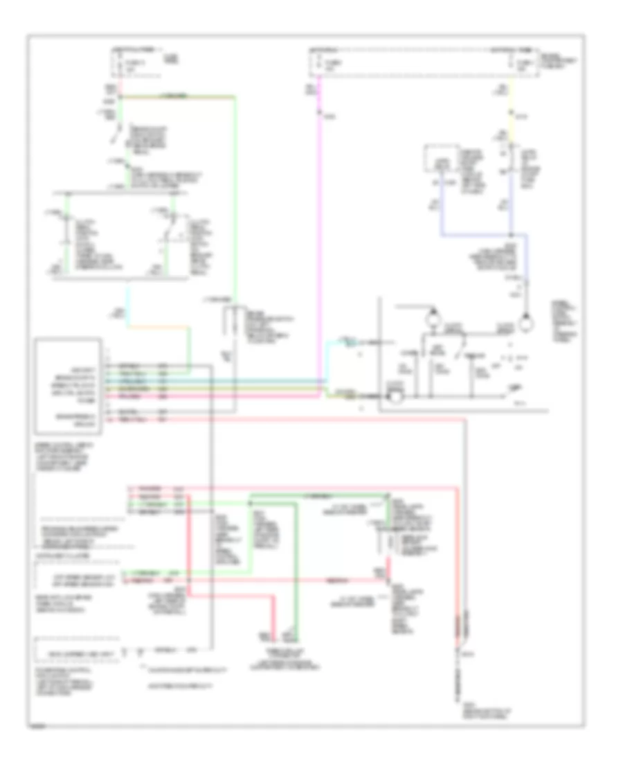
CRUISE CONTROL
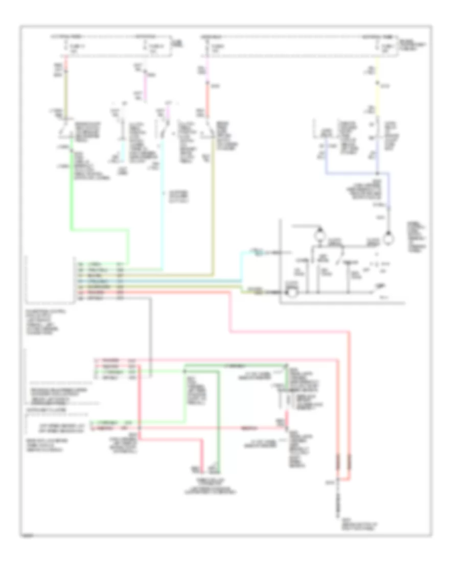
Cruise Control Wiring Diagram, Diesel for Ford F-Super Duty 1997
List of elements for Cruise Control Wiring Diagram, Diesel for Ford F-Super Duty 1997:
- (behind bottom of right kick panel)
- (behind glove box)
- (behind left side of instrument panel)
- (left rear of engine compartment, on bracket)
- (left side of firewall, left of main harness, connectors)
- (not used)
- (on rear axle assembly)
- 10a
- 15a
- 49 states or super duty only
- A/t
- Accel
- Brake on/off (boo) switch (on bracket, above brake pedal)
- C240
- Clock- spring
- Clutch pedal position (ccp) switch (on bracket, above clutch pedal)
- Clutch pedal position (ccp) switch jumper (taped to main harness, near steering column)
- Coast
- Diff speed sensor high
- Diff speed sensor low
- Engine compartment fuse box
- Fuse 13
- Fuse 18
- Fuse 3 30a
- Fuse 5 15a
- Fuse panel
- G203
- Horn
- Horn relay
- Horn relay (in engine compt fuse box)
- Hot at all times
- Hot in run
- Instrument cluster
- M/t
- Nca
- Off
- Ohms
- Powertrain control module (pcm)
- Programmable speedometer/ odometer module (psom)
- Rabs data link connector
- Rear anti-lock brake (rabs) module
- Rear axle sensor
- Red/
- Red/ pnk
- Red/pnk
- Remote keyless entry (rke) module (behind left side of dash)
- Resume
- S105
- S115
- S208 (main harness, near breakout to remote keyless entry module)
- S216
- S236
- S240 (main harn, in breakout to clutch pedal position switch or jumper)
- S242
- S247 (main harness, left rear of engine compt, on firewall)
- S248 (main harness, left rear of engine compt, on firewall)
- S429 (rear lamps harness, near breakout to ouput shaft speed sensor)
- S429 (rear lamps harness, near breakout to output shaft speed sensor)
- Set/
- Speed control/ horn switch assembly (in steering wheel)
- W/ 152" wheel base or greater
Cruise Control Wiring Diagram, Gasoline for Ford F-Super Duty 1997
List of elements for Cruise Control Wiring Diagram, Gasoline for Ford F-Super Duty 1997:
- (behind bottom of right kick panel)
- (behind glove box)
- (behind left side of instrument panel)
- (left rear of engine compartment, on bracket)
- (left side of engine compartment, near master cylinder)
- (left side of firewall, left of main harness connectors)
- (on rear axle assembly)
- 15a
- 49 states or super duty
- A/t
- Accel
- Brake on/off (boo) switch (on bracket, above brake pedal)
- Brake on/off in
- Brake press in
- Brake pressure switch (on left frame rail, below driver's floor pan)
- C240
- California except super duty
- Clock- spring
- Clutch pedal position (ccp) switch (on bracket, above clutch pedal)
- Clutch pedal position (ccp) switch jumper (taped to main harness, near steering column)
- Coast
- Diff speed sensor high
- Diff speed sensor low
- Engine compartment fuse box
- Fuse 13
- Fuse 3 30a
- Fuse 5 15a
- Fuse panel
- G203
- Ground
- Horn
- Horn relay
- Horn relay (in engine compt fuse box)
- Hot at all times
- Hot in run
- Instrument cluster
- M/t
- Nca
- Off
- Ohms
- Power
- Powertrain control module (pcm)
- Programmable speedometer/ odometer module (psom)
- Rabs data link connector
- Rear anti-lock brake (rabs) module
- Rear axle sensor
- Red/ pnk
- Red/pnk
- Remote keyless entry (rke) module (behind left side of dash)
- Resume
- S105
- S115
- S208 (main harness, near breakout to remote keyless entry module)
- S216
- S236
- S240 (main harness, in breakout to clutch pedal position switch or jumper)
- S246 (main harness, near breakout to speed control amplifier)
- S247 (main harness, left rear of engine compt, on firewall)
- S248 (main harness, left rear of engine compt, on firewall)
- S429 (rear lamps harness, near breakout to ouput shaft speed sensor)
- S429 (rear lamps harness, near breakout to output shaft speed sensor)
- Set/
- Spd ctrl sw rtn
- Speed control servo/ amplifier assembly
- Speed control/ horn switch assembly (in steering wheel)
- Speed ctrl sw in
- Vehicle speed (vss) input
- Vss input
- W/ 152" wheel base or greater
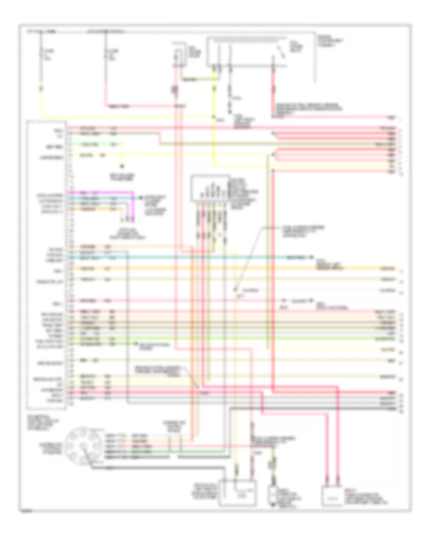
ENGINE PERFORMANCE
5.8L
5.8L, Engine Performance Wiring Diagrams, California (1 of 4) for Ford F-Super Duty 1997
List of elements for 5.8L, Engine Performance Wiring Diagrams, California (1 of 4) for Ford F-Super Duty 1997:
- (engine control sensor harness, near brake warning resistor/diode assembly) s136
- (engine control sensor harness, near breakout to pcm)
- (fuel charge harness, near breakout to distributor)
- (fuel charge harness, near breakout to ignition coil)
- (low range indicator)
- A/c clutch sig
- Air conditioning system
- Aird solenoid
- Bbp feed
- Body builder power feed
- Case gnd
- Ckp sensor
- Coil
- Data link (+)
- Data link (-)
- Data link connector (right side of dash)
- Data link feps
- Distributor (top front of engine)
- Distributor ignition shield
- Ect sens
- Egr solnd ctrl
- Engine compartment fuse box
- Fuel pump mon
- Fuse 20a
- Fuse 30a
- G104 (rear of left fender apron)
- G108 (left front radiator support)
- G203 (right kick panel)
- Hot at all times
- Hot in start or run
- Iat sens
- Idm
- Idm (fto)
- Ign gnd
- Ignition coil (left side of engine, above valve cover)
- Ignition control module (left rear side of engine compartment, on fender apron)
- Instrument cluster system
- Low rnge 4x4
- Maf sig rtn
- Mil
- Misfire sens
- Nca
- Pcm power diode
- Pcm power relay
- Pip
- Pnk
- Power
- Powertrain control module (top left side of firewall)
- Pwr gnd
- Pwr grd
- Radio capacitor (left side of engine, near coil)
- Red
- Red/
- Rr ho2s sig
- S102
- S104
- S145
- S148
- S171
- S199
- S216
- Spout
- Spout check connector (left rear of engine compartment, near icm)
- Trans ctrl sw
- Trans temp
- Tss 1
- Tss 2
- Vss (-)
5.8L, Engine Performance Wiring Diagrams, California (2 of 4) for Ford F-Super Duty 1997
List of elements for 5.8L, Engine Performance Wiring Diagrams, California (2 of 4) for Ford F-Super Duty 1997:
- (fuel charge harness, near breakout to fuel injector 3)
- C250
- C251
- C252
- Delta pressure feedback egr sensor (5.8l - on top right front of of engine) (7.5l - on lrft side of throttle body)
- Engine compartment fuse box
- Engine coolant temperature sensor (left front of engine, near distributor)
- Fuel pump relay
- Fuse 20a
- Hot at all times
- Instrument cluster
- Intake air temperature sensor (top center of engine, behind distributor)
- Malfunction indicator input
- Misfire sensor (center front of engine, on timing chain cover)
- Misfire sensor shield
- Nca
- Psom vehicle speed output
- Red
- Rpm input
- S135 (fuel charge harness, near breakout to canister purge solenoid)
- S151
- S246 (main harness, near breakout to speed control amplifier)
- Throttle position sensor (top left front of engine, on throttle body)
5.8L, Engine Performance Wiring Diagrams, California (3 of 4) for Ford F-Super Duty 1997
List of elements for 5.8L, Engine Performance Wiring Diagrams, California (3 of 4) for Ford F-Super Duty 1997:
- (engine control sensor harness, near breakout to brake warning resistor/diode assembly)
- (fuel charge harness, near breakout to act solenoid)
- (fuel charge harness, near breakout to fuel injector 3)
- (not used)
- 5.8l
- 7.5l
- Coast clutch solenoid
- E4od transmission
- Egr control solenoid (5.8l - on ignition coil support bracket) (7.5l - in left side of engine compt)
- Electronic pressure control solenoid
- Front tank fuel pump/ fuel gauge sender
- Fuel tank selector switch
- G108 (on upper left radiator support)
- Idle air control valve (on throttle body)
- Inertia fuel shut-off switch (behind right kick panel)
- Injectors fuel
- Nca
- Rear tank fuel pump/ fuel gauge sender
- Red
- S137
- S149
- S151
- S169
- S400
- Secondary air injection bypass (airb) solenoid (7.5l) (near ignition coil)
- Secondary air injection diverter (aird) solenoid (7.5l) (rear of left valve cover)
- Shift solenoids
- Ss1
- Ss2
- Tan
- Tan/ red
- Tan/red
- Torque converter clutch solenoid
- Transmission fluid temperature sensor
- Vapor management valve (center of engine)
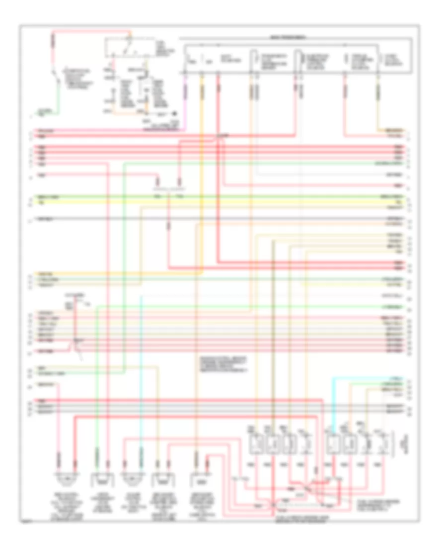
5.8L, Engine Performance Wiring Diagrams, California (4 of 4) for Ford F-Super Duty 1997
List of elements for 5.8L, Engine Performance Wiring Diagrams, California (4 of 4) for Ford F-Super Duty 1997:
- (engine control sensor harness, in breakout to engine compt. fuse panel box)
- (engine control sensor harness, near breakout to pcm)
- (main harness, near breakout to clutch pedal position switch or jumper) s240
- (not used)
- 5.8l
- 7.5l
- Airb solenoid
- Batt
- Brake on/off
- Brake on/off (boo) switch (on bracket, above brake pedal)
- Coast clutch
- Dpfe sens
- Epc sol
- Fuel inj 1
- Fuel inj 2
- Fuel inj 3
- Fuel inj 4
- Fuel inj 5
- Fuel inj 6
- Fuel inj 7
- Fuel inj 8
- Fuel pump ctrl
- Fuse 10a
- Fuse 15a
- Fuse panel
- G101 (right fender apron, right side of battery)
- H02s heater ctrl
- Heated oxygen sensor 11 (near top of transmission)
- Heated oxygen sensor 12 (near rear of transmission)
- Heated oxygen sensor 21 (near left side of transmission)
- Hot at all times
- Hot in run or start
- Iac sol
- Lf ho2s sig
- Maf sens in
- Mass air flow sensor (right front side of engine compartment)
- Misfire in
- Nca
- Power
- Power gnd
- Powertrain control module (top left side of firewall)
- Pwr gnd
- Red
- Ref volt
- Rf ho2s sig
- S106
- S122
- S123
- S146
- S215
- S236
- Sig rtn
- Tan
- Tan/red
- Tcc sol
- Tp sens in
- Tr sens in
- Trans ctrl ind
- Trans- mission control switch
- Transmission range sensor (lower left side of transmission)
- Vapor valve
- Vss (+)
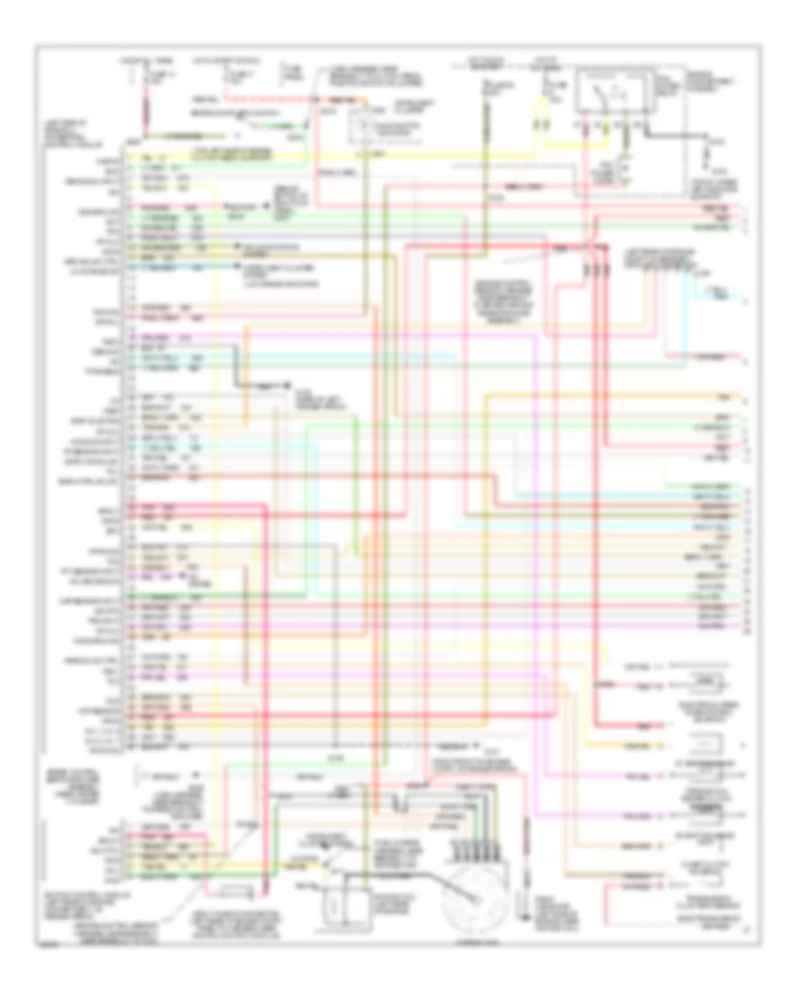
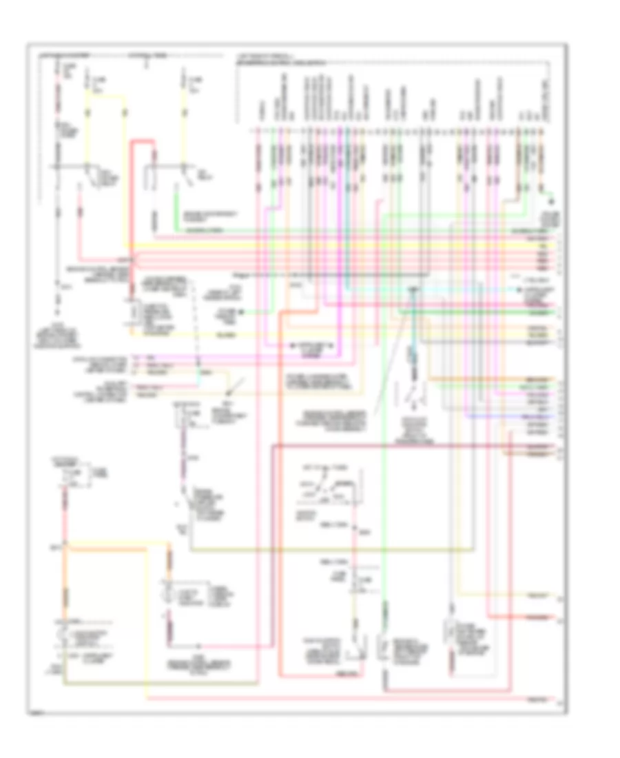
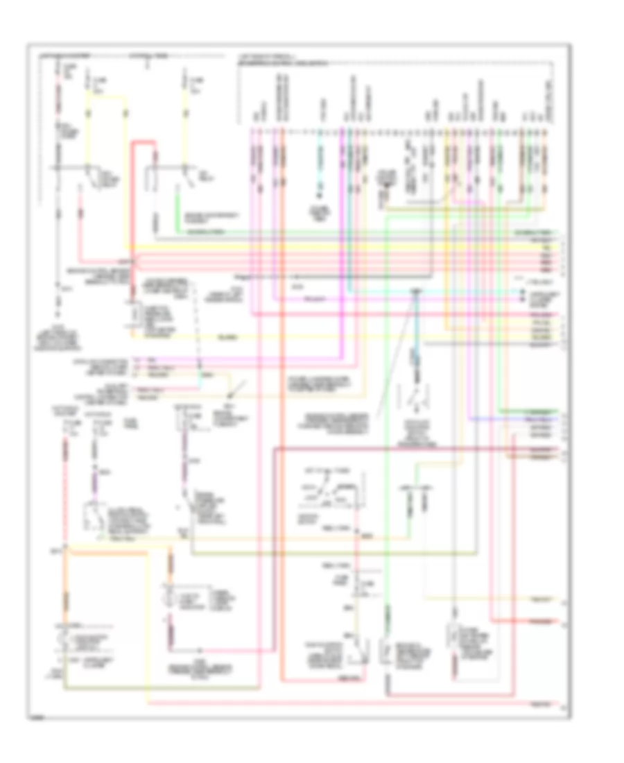
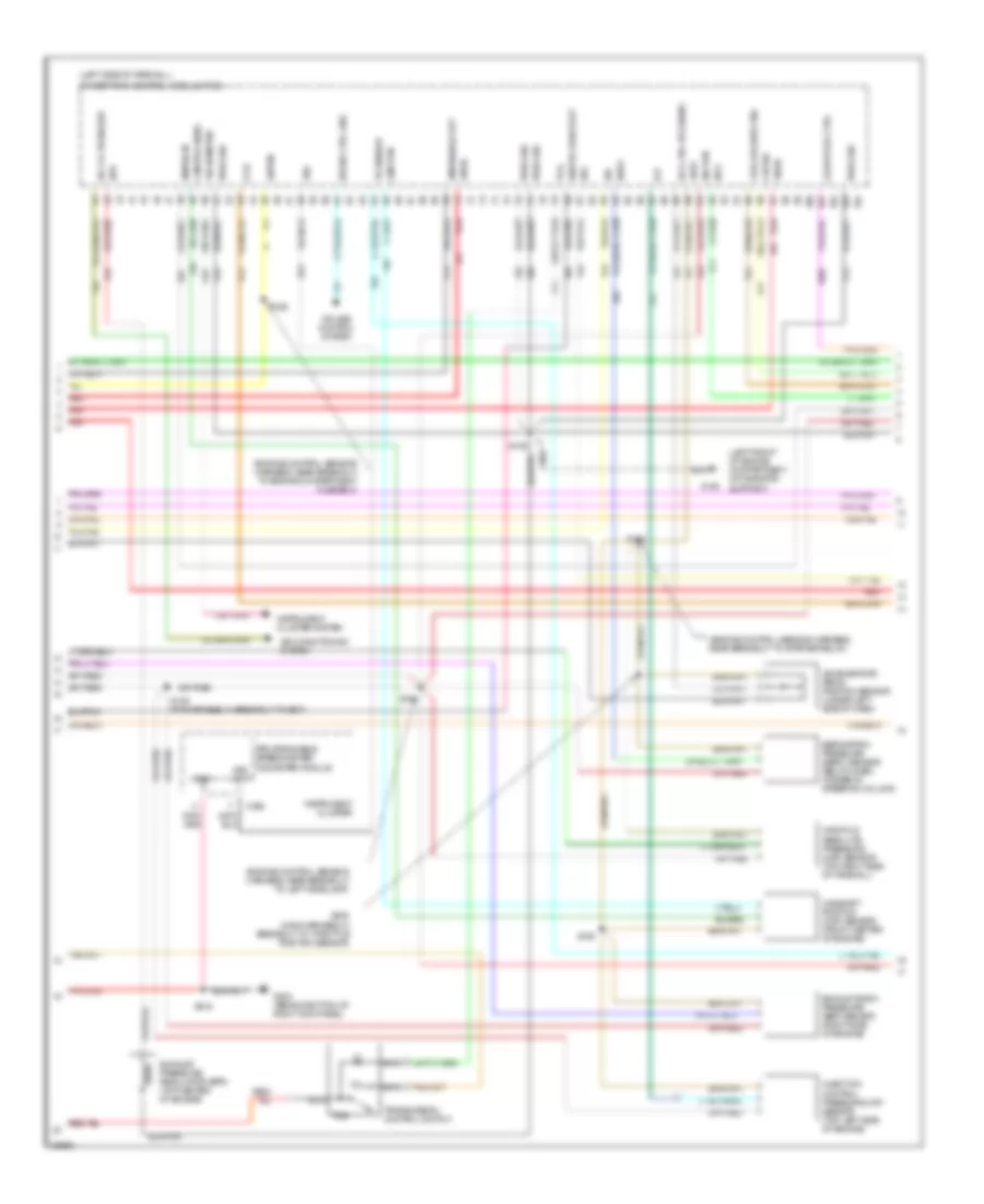
5.8L, Engine Performance Wiring Diagrams, Federal (1 of 2) for Ford F-Super Duty 1997
List of elements for 5.8L, Engine Performance Wiring Diagrams, Federal (1 of 2) for Ford F-Super Duty 1997:
- #1 shift solenoid
- #2 shift solenoid
- (behind bottom of right kick panel) g203
- (engine control sensor harness, near breakout near breakout to pcm)
- (engine control sensor harness, near breakout to brake warning resistor/diode assembly)
- (fuel charge harness, near breakout to distributor)
- (left rear of engine compt, on bracket) data link connector
- (left side of firewall) powertrain control module
- (low range indicator)
- (main harness, near breakout to clutch pedal position switch or jumper)
- (right front of engine compt, on fender apron)
- (top left side of brake/ clutch pedal support)
- (top of upper left radiator support)
- A/c demand sig
- A/c system
- Accs
- Air conditioning system
- Airb solnd ctrl
- Aird solnd ctrl
- Boo
- Brake on/off (boo) switch
- C198
- C250
- C251
- Ccs
- Ckp sensor
- Coast clutch solenoid
- Coil
- Coil wire
- Cse gnd
- Distributor
- E40d transmission
- Ect
- Egr cntrl solnd.
- Egr valve pos
- Electronic pres- sure control solenoid
- Engine compartment fuse box
- Epc
- Evap can solnd.
- Fp enable
- Fpm
- Fuse 13 15a
- Fuse 17 10a
- Fuse 22 20a
- Fuse 30a
- Fuse panel
- G101
- G104 (rear of left fender apron)
- G108
- Gnd
- Ho2s ground
- Ho2s sig input
- Hot at all times
- Hot in run or start
- Hot in start or run
- Iac
- Iat
- Idm
- Idm (fto)
- Ign gnd
- Ignition coil (left rear of engine)
- Ignition control module (left rear of engine compartment, on fender apron)
- Inj 1, 4, 5, 8
- Inj 2, 3, 6, 7
- Instrument cluster
- Instrument cluster system
- Kapwr
- Low range ind
- Malfunction indicator
- Map sensor input
- Nca
- Pcm power diode
- Pcm power relay
- Pip
- Pnk
- Pwr
- Pwr gnd
- Radio capacitor (left side of engine, near ignition coil)
- Red
- S102
- S106
- S136
- S145
- S148
- S169
- S171
- S199
- S215
- S216
- S236
- S240
- S246 (main harness, near breakout to speed control amplifier)
- Sig rtn
- Speed control servo/amplifier assembly (near master cylinder)
- Spout
- Spout check connector (left rear of engine compt, taped to harness, near ignition control module)
- Sto/mil
- Tan
- Tcc
- Tcil
- Tcs
- Tft sensor input
- Torque con- verter clutch solenoid
- Tps input
- Tr sensor input
- Transmission fluid temp sensor
- Tss 1
- Tss 2
- Vip dlc
- Vpwr
- Vref
- Vss ground
- Vss signal input
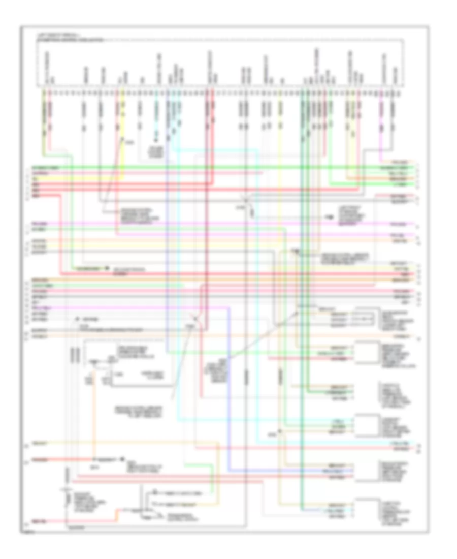
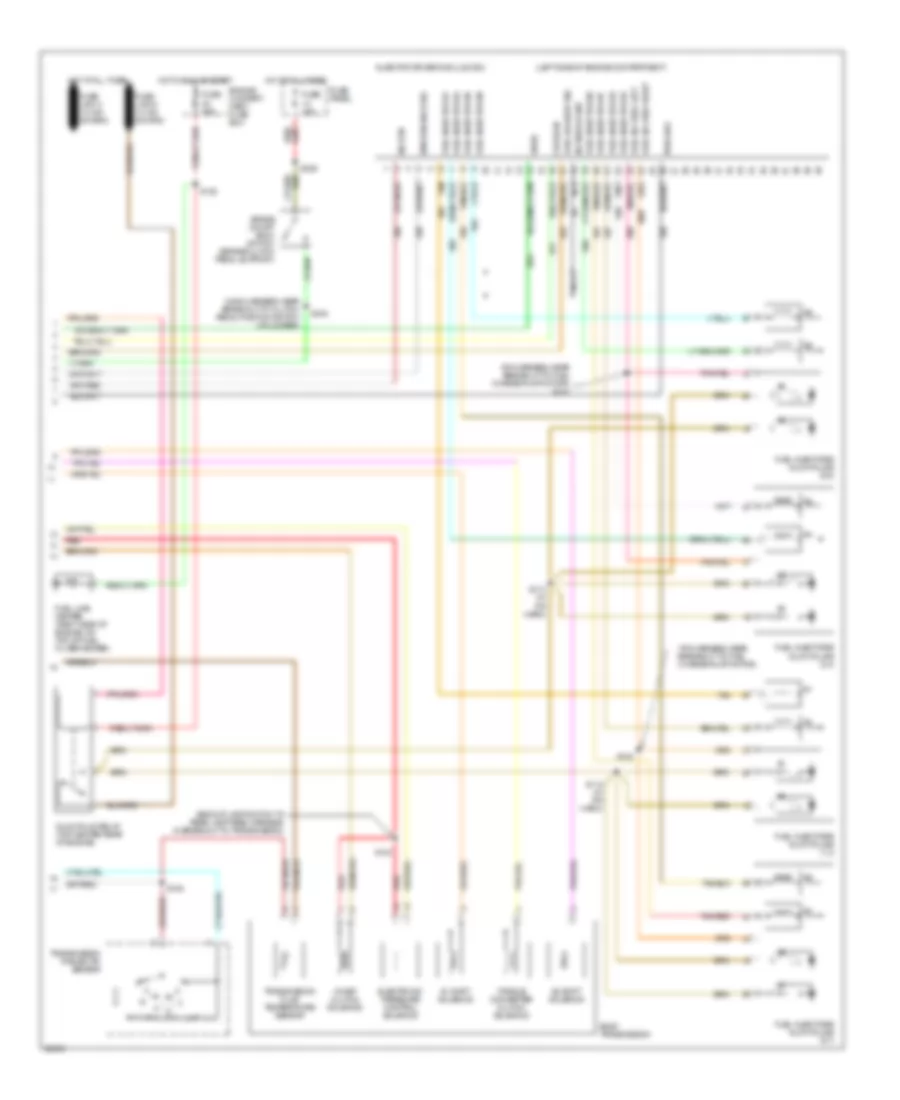
5.8L, Engine Performance Wiring Diagrams, Federal (2 of 2) for Ford F-Super Duty 1997
List of elements for 5.8L, Engine Performance Wiring Diagrams, Federal (2 of 2) for Ford F-Super Duty 1997:
- (engine control sensor harness, near breakout to brake warning resistor/diode assembly)
- (engine control sensor harness, near breakout to left head- lamp)
- (engine control sensor harness, near breakout to powertrain control module)
- (fuel charge harn, near breakout to fuel inj 5)
- (fuel charge harn, near breakout to fuel inj 8)
- (fuel charge harness, near breakout to air charge temperature solenoid)
- (fuel charge harness, near breakout to canister purge solenoid)
- (fuel charge harness, near breakout to fuel injector 3)
- (not used)
- (on upper left radiator support) g108
- (on upper radiator support)
- 5.8l
- 7.5l
- A/t
- C199
- Data link connector (left rear of engine compt, on bracket)
- Egr control solenoid (on ignition coil support bracket)
- Egr valve position sensor (top right front of engine)
- Engine compart- ment fuse box
- Engine compartment fuse box
- Engine coolant temperature sensor (5.8l - on thermostat housing) (7.5l - on left side of distributor)
- Evap canister purge solenoid (right front of engine)
- Front tank fuel pump/ fuel gauge sender
- Fuel injectors
- Fuel pump relay
- Fuel tank selector switch
- Fuse 16 20a
- Fuse 5 15a
- G108
- Heated oxygen sensor no.11 (near top of trans)
- Hot at all times
- Hot in run
- Idle air control valve (top of throttle body)
- Inertia fuel shut-off switch (behind right kick panel)
- Intake air temperature sensor (top center front of engine, near intake runner #6)
- M/t
- Manifold absolute pressure sensor (top right side of firewall)
- Nca
- Rear tank fuel pump/ fuel gauge sender
- Red
- S102
- S122
- S134
- S135
- S137
- S146
- S149
- S151
- S159
- S160
- S163
- S165
- S400
- Secondary air injection bypass solenoid (7.5l) (near rear of left valve cover)
- Secondary air injection diverter solenoid (near rear of left valve cover)
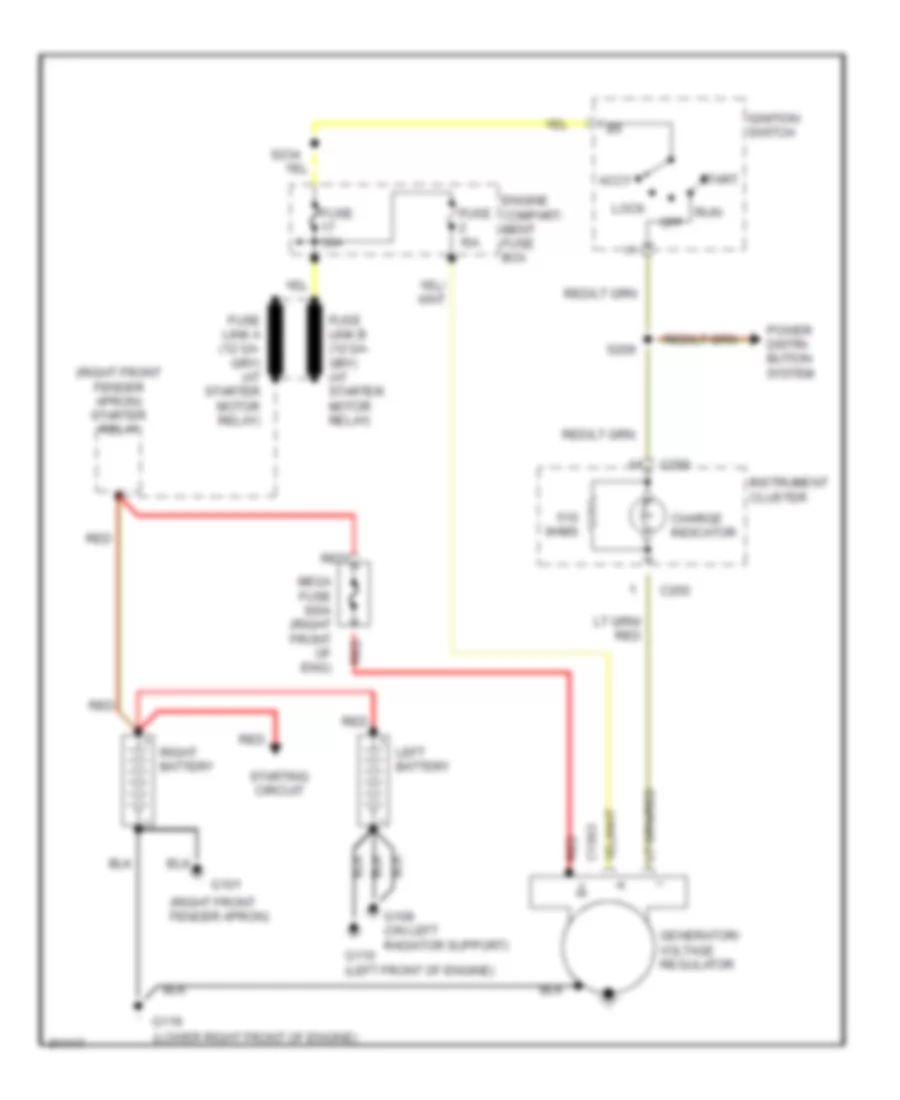
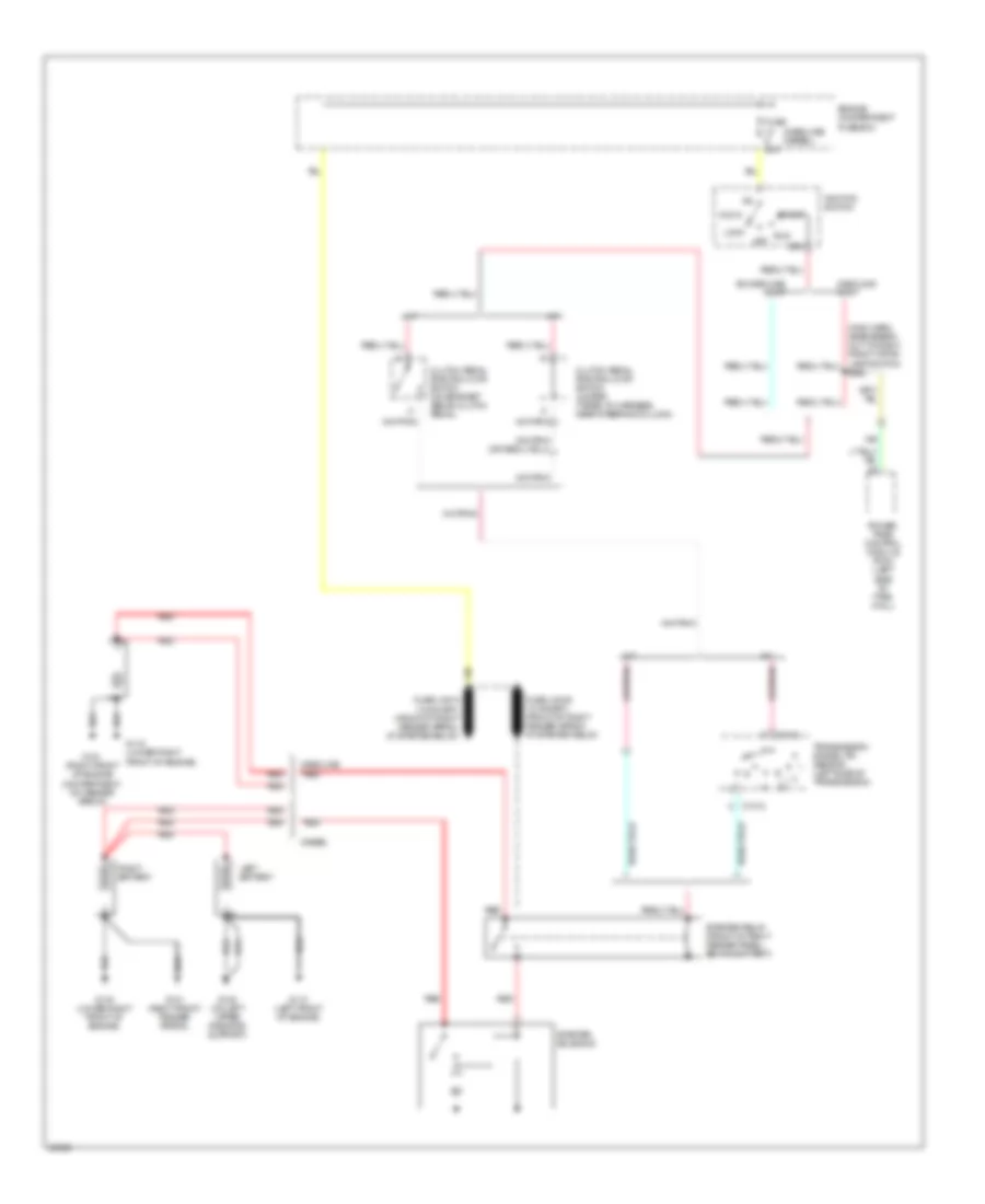
- Starting/ charging system
- Tan
- Tcil
- Throttle position sensor (top right front of engine, on throttle body)
- Transmission control switch
- Transmission range sensor (left side of transmission)
7.3L
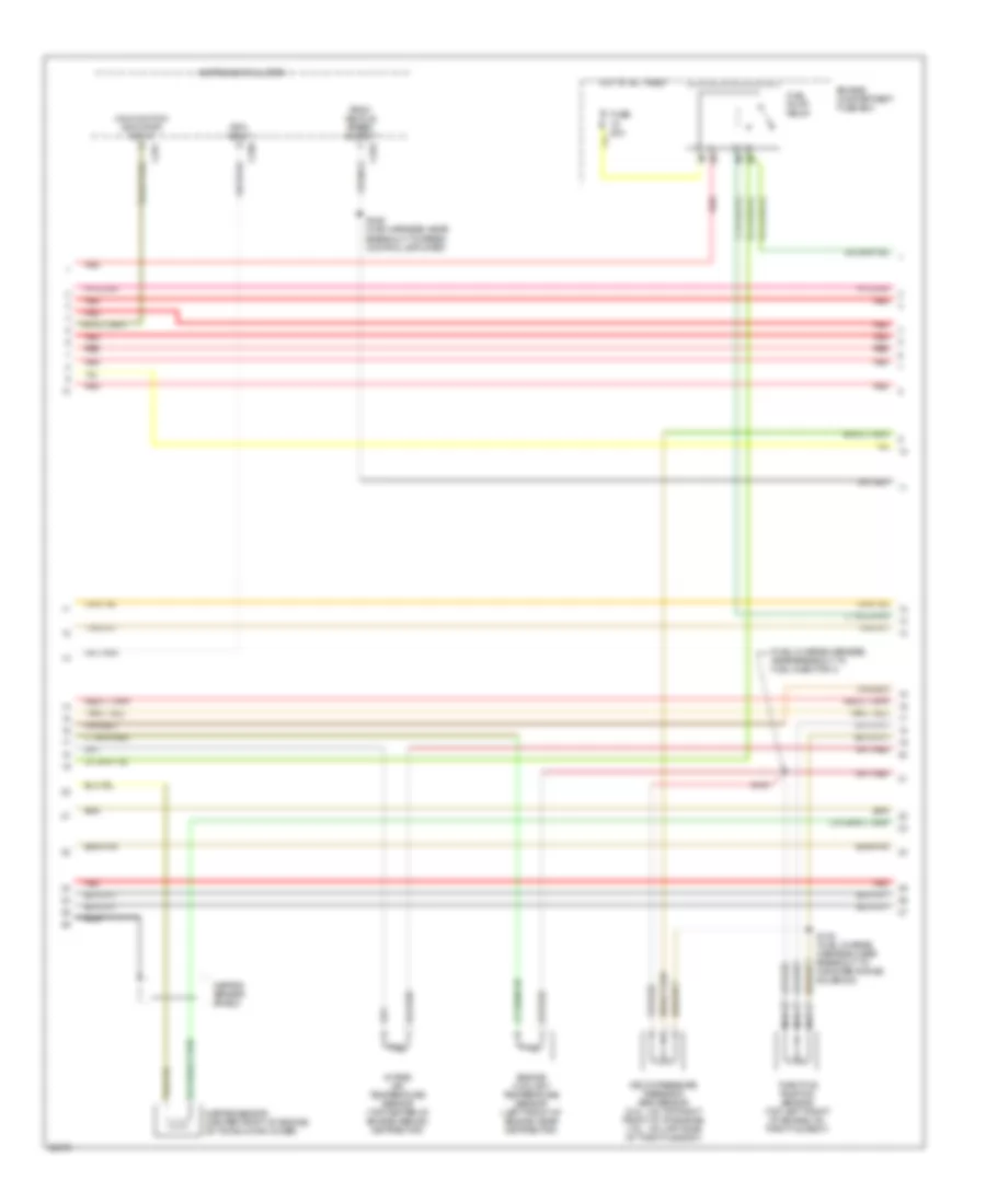
7.3L DI Turbo Diesel, Engine Performance Wiring Diagrams, California (1 of 3) for Ford F-Super Duty 1997
List of elements for 7.3L DI Turbo Diesel, Engine Performance Wiring Diagrams, California (1 of 3) for Ford F-Super Duty 1997:
- "wait to start" indicator
- (engine control sensor harness, near breakout to brake warning resistor/ diode assembly)
- (engine control sensor harness, near breakout to pcm)
- (in main harness, near breakout to lower center of dash)
- (left side of firewall)
- (power lumbar/bolster harness, near breakout to lower center of dash)
- 4x4 hi/low indicator switch (front of transfer case)
- Acc
- Aux rpm input
- Auxiliary powertrain control connector (center of dash)
- Brake press sw
- Brake warning ind
- C250
- C251
- Cam pos sens
- Ccs
- Cruise control system
- Data link connector (behind lower center of dash)
- Diesel warning lamps display
- Dlc
- Ebp
- Engine compartment fuse box
- Engine oil temperature (eot) sensor (front top of engine)
- Eot
- Fuse 10a
- Fuse 15a
- Fuse 20a
- Fuse 30a
- Fuse 3a
- Fuse panel
- G104 (rear of left fender apron)
- G108 (left front of engine compart- ment, on upper radiator support)
- Glow plug relay
- Gnd
- Hot at all times
- Hot in run
- Hot in run or start
- Iat
- Idle validation sw
- Idle validation switch (open at idle) (near accele- rator pedal)
- Idm relay
- Ignition switch
- Injection pressure regulator (ipr) (top center of engine)
- Instrument cluster
- Instrument cluster system
- Intake air temper- ature (iat) sensor (top center of engine)
- Lock
- Low range 4x4 sw
- Malfunction indicator lamp (mil)
- Nca
- Off
- Pcm dlc
- Pcm power diode
- Pcm power relay
- Power take-off feed
- Powertrain control module (pcm)
- Pto feed
- Pwr gnd
- Red
- Run
- S101
- S105
- S125
- S157
- S166 (engine control sensor harness, near breakout to pcm)
- S174
- S206
- S215
- S241
- S243
- Speed ctrl gnd
- Ss1
- Start
- Tachometer
- Tcil
- Tcs
- Tft
- Vss gnd
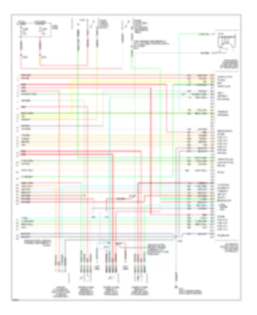
7.3L DI Turbo Diesel, Engine Performance Wiring Diagrams, California (2 of 3) for Ford F-Super Duty 1997
List of elements for 7.3L DI Turbo Diesel, Engine Performance Wiring Diagrams, California (2 of 3) for Ford F-Super Duty 1997:
- (engine control harness, near breakout to engine compt fuse box)
- (engine control sensor harness, near breakout to left headlamp)
- (engine control sensor harness, near breakout to starter relay)
- (left front of engine compartment, on radiator support)
- (left side of firewall)
- A/c cyl press sw
- Accelerator pedal position sensor (under left side of dash)
- Accl pdl pos sens
- Air conditioning system
- Baro
- Barometric pressure (baro) sensor (below dash, at base of steering column)
- Boo
- C252
- Camshaft position (cmp) sensor (front center of engine)
- Cid sig
- Cmp rtn
- Cruise control system
- Epc
- Epr
- Exhaust back pressure (ebp) sensor (right side of engine)
- Exhaust pressure regulator (epr) (top center of engine)
- Fuel delivery sig
- G108
- G203 (behind bottom of right kick panel)
- Glow plug ctrl
- Gnd
- Icp
- Idm enable out
- Idm sig in
- Injection control pressure (icp) sensor (top left side of engine)
- Instrument cluster
- Ipr
- Kapwr
- Manifold absolute pressure (map) sensor (top right side of firewall)
- Map
- Nca
- Powertrain control module (pcm)
- Programmable speedometer/ odometer module
- Pwr gnd
- Red
- S106
- S126
- S129 (pia harness, in breakout to ect)
- S163
- S164
- S192
- S216
- S235 (main harn, in breakout to throttle position sensor)
- Sig rtn
- Speed ctrl gnd
- Tcc
- Tcil
- Tcs
- Tr sensor
- Transmission control switch
- Vpwr
- Vref
- Vss
- Vss out
- Wait to start out
7.3L DI Turbo Diesel, Engine Performance Wiring Diagrams, California (3 of 3) for Ford F-Super Duty 1997
List of elements for 7.3L DI Turbo Diesel, Engine Performance Wiring Diagrams, California (3 of 3) for Ford F-Super Duty 1997:
- #1 shift solenoid
- #2 shift solenoid
- (backup lamp switch to rear lamp feed harness, in breakout)
- (in pia harn)
- (left side of engine compartment)
- (main harness, near breakout to clutch pedal position switch or jumper)
- (pia harness, near breakout to fuel charge pump motor)
- (pia harness, near breakout to fuel charge pump motor) s141
- Brake on/off (boo) switch (on bracket, above brake pedal)
- Cid sig in
- Coast clutch solenoid
- E4od transmission
- Electronic pressure control solenoid
- Engine compart- ment fuse box
- Fuel delivery sig
- Fuel inj feed left
- Fuel inj feed right
- Fuel injector #1
- Fuel injector #2
- Fuel injector #3
- Fuel injector #4
- Fuel injector #5
- Fuel injector #6
- Fuel injector #7
- Fuel injector #8
- Fuel injectors/ glow plugs (1,3)
- Fuel injectors/ glow plugs (2,4)
- Fuel injectors/ glow plugs (5,7)
- Fuel injectors/ glow plugs (6,8)
- Fuel line heater (right side of engine, on top of fuel filter/heater)
- Fuse 15a
- Fuse 30a
- Fuse panel
- Glow plug relay (top center rear of engine)
- Hot at all times
- Hot in run or start
- Idm feedback sig
- Inj shield gnd
- Injector driver module (idm)
- Nca
- Pwr gnd
- Red
- S112
- S113
- S128
- S142
- S143
- S146
- S236
- S240
- Sig rtn
- Tan
- Tan/red
- Torque converter clutch solenoid
- Transmission fluid temperature sensor
- Transmission range (tr) sensor
- Vpwr
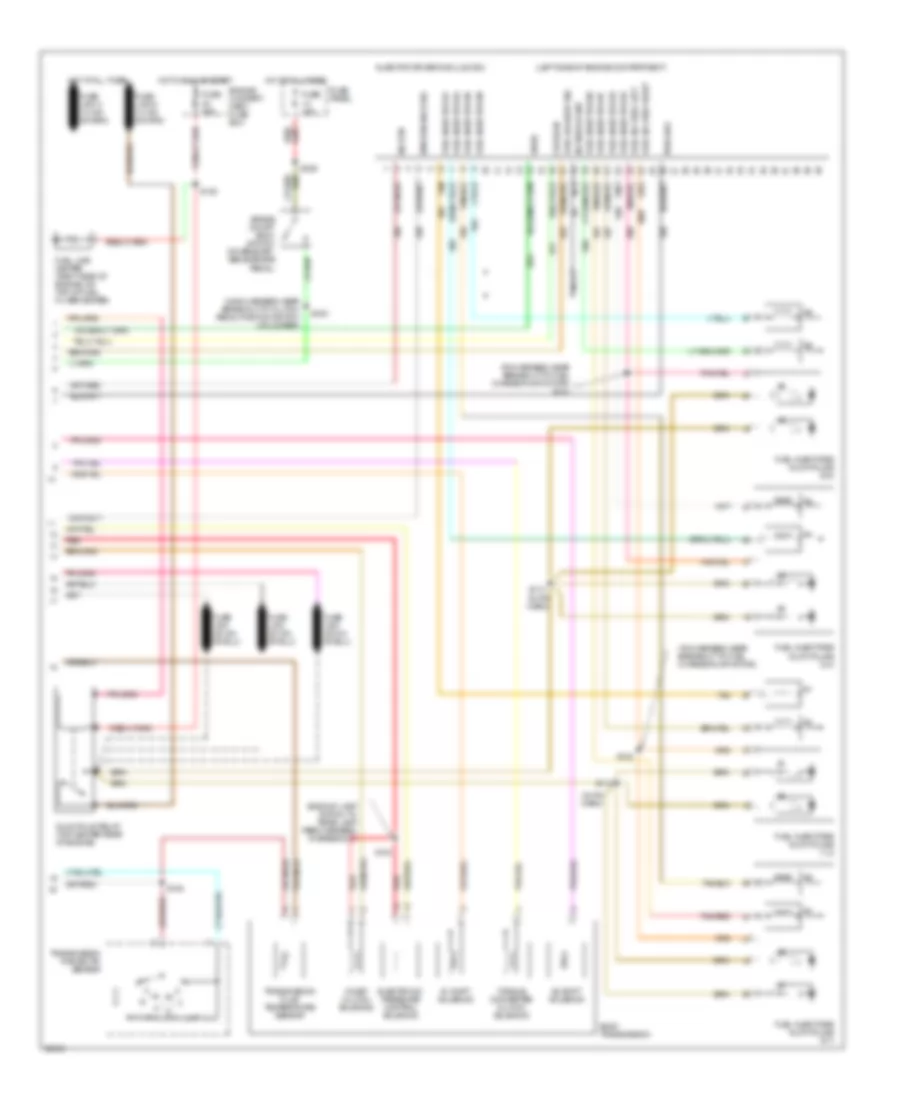
7.3L DI Turbo Diesel, Engine Performance Wiring Diagrams, Federal (1 of 3) for Ford F-Super Duty 1997
List of elements for 7.3L DI Turbo Diesel, Engine Performance Wiring Diagrams, Federal (1 of 3) for Ford F-Super Duty 1997:
- "wait to start" indicator
- (a/t)
- (engine control sensor harness, near breakout to brake warning resistor/ diode assembly)
- (engine control sensor harness, near breakout to pcm)
- (in main harness, near breakout to lower center of dash)
- (left side of firewall)
- (m/t)
- (power lumbar/bolster harness, near breakout to center of dash)
- 4x4 hi/low indicator switch (front of transfer case)
- A/t
- Acc
- Aux rpm input
- Auxiliary powertrain control connector (center of dash)
- Brake press sw
- Brake warning ind
- C250
- C251
- Clutch pedal position switch (top right side of brake/clutch pedal support)
- Cruise control system
- Data link connector (behind lower center of dash)
- Diesel warning lamps display
- Dlc
- Ebp
- Engine compartment fuse box
- Engine oil temperature (eot) sensor (front top of engine)
- Eot
- Fuse 10a
- Fuse 15a
- Fuse 20a
- Fuse 30a
- Fuse 3a
- Fuse panel
- G104 (rear of left fender apron)
- G108 (left front of engine compart- ment, on upper radiator support)
- Gnd
- Hot at all times
- Hot in run
- Hot in run or start
- Iat
- Idle validation sw
- Idle validation switch (open at idle) (near accele- rator pedal)
- Idm relay
- Ignition switch
- Injection pressure regulator (ipr) (top center of engine)
- Instrument cluster
- Instrument cluster system
- Intake air temper- ature (iat) sensor (top center of engine)
- Lock
- Low range 4x4 sw
- M/t
- Malfunction indicator lamp (mil)
- Map
- Nca
- Off
- Pcm dlc
- Pcm power diode
- Pcm power relay
- Power take-off feed
- Powertrain control module (pcm)
- Pto feed
- Pwr gnd
- Red
- Run
- S101
- S105
- S125
- S157
- S166 (engine control sensor harness, near breakout to pcm)
- S174
- S206
- S215
- S241
- S242
- S243
- Speed ctrl gnd
- Ss1
- Ss2
- Start
- Tcc
- Tcs or cpp
- Tft
- Vss gnd
7.3L DI Turbo Diesel, Engine Performance Wiring Diagrams, Federal (2 of 3) for Ford F-Super Duty 1997
List of elements for 7.3L DI Turbo Diesel, Engine Performance Wiring Diagrams, Federal (2 of 3) for Ford F-Super Duty 1997:
-
-
- (engine control sensor harness, near breakout to engine compartment fuse box)
- (engine control sensor harness, near breakout to left headlamp)
- (engine control sensor harness, near breakout to starter relay)
- (left front of engine compartment, on radiator support)
- (left side of firewall)
- A/c cyl press sw
- Accelerator pedal position sensor (under left side of dash)
- Accl pdl pos sens
- Air conditioning system
- Baro
- Barometric pressure (baro) sensor (below dash, at base of steering column)
- Boo
- C252
- Cam pos sens
- Camshaft position (cmp) sensor (front center of engine)
- Ccs
- Cid sig
- Cmp rtn
- Cruise control system
- Epc
- Epr
- Exhaust back pressure (ebp) sensor (right side of engine)
- Exhaust pressure regulator (epr) (top center of engine)
- Fuel delivery sig
- G108
- G203 (behind bottom of right kick panel)
- Glow plug ctrl
- Gnd
- Icp
- Idm enable out
- Idm sig in
- Injection control pressure (icp) sensor (top left side of engine)
- Instrument cluster
- Instrument cluster system
- Ipr
- Kapwr
- Manifold absolute pressure (map) sensor (top right side of firewall)
- Nca
- Powertrain control module (pcm)
- Programmable speedometer/ odometer module
- Pwr gnd
- Red
- S106
- S126
- S129 (pia harness, in breakout to ect)
- S163
- S164
- S192
- S216
- S235 (main harness, in breakout to throttle position sensor)
- Sig rtn
- Speed ctrl gnd
- Tachometer
- Tcil
- Tcs
- Tr sensor
- Transmission control switch
- Vpwr
- Vref
- Vss
- Vss out
- Wait to start out
7.3L DI Turbo Diesel, Engine Performance Wiring Diagrams, Federal (3 of 3) for Ford F-Super Duty 1997
List of elements for 7.3L DI Turbo Diesel, Engine Performance Wiring Diagrams, Federal (3 of 3) for Ford F-Super Duty 1997:
- #1 shift solenoid
- #2 shift solenoid
- (backup lamp switch to rear lamp feed harness, in breakout to transmission)
- (left side of engine compartment)
- (main harness, near breakout to clutch pedal position switch or jumper)
- (pia harness, near breakout to fuel charge pump motor)
- (pia harness, near breakout to fuel charge pump motor) s141
- Brake on/off (boo) switch (brake/clutch pedal support)
- Cid sig in
- Coast clutch solenoid
- E4od transmission
- Electronic pressure control solenoid
- Engine compart- ment fuse box
- Fuel delivery sig
- Fuel inj feed left
- Fuel inj feed right
- Fuel injector #1
- Fuel injector #2
- Fuel injector #3
- Fuel injector #4
- Fuel injector #5
- Fuel injector #6
- Fuel injector #7
- Fuel injector #8
- Fuel injectors/ glow plugs (1,3)
- Fuel injectors/ glow plugs (2,4)
- Fuel injectors/ glow plugs (5,7)
- Fuel injectors/ glow plugs (6,8)
- Fuel line heater (right side of engine, on top of fuel filter/heater)
- Fuse 15a
- Fuse 30a
- Fuse panel
- Glow plug relay (top center rear of engine)
- Hot at all times
- Hot in run or start
- Idm feedback sig
- Inj shield gnd
- Injector driver module (idm)
- Nca
- Pwr gnd
- Red
- S112 (in pia harn)
- S113 (in pia harn)
- S128
- S142
- S143
- S146
- S236
- S240
- Sig rtn
- Tan
- Tan/red
- Torque converter clutch solenoid
- Transmission fluid temperature sensor
- Transmission range (tr) sensor
- Vpwr
7.5L
7.5L, Engine Performance Wiring Diagrams, California (1 of 4) for Ford F-Super Duty 1997
List of elements for 7.5L, Engine Performance Wiring Diagrams, California (1 of 4) for Ford F-Super Duty 1997:
- (engine control sensor harness, near brake warning resistor/diode assembly) s136
- (engine control sensor harness, near breakout to pcm)
- (fuel charge harness, near breakout to distributor)
- (fuel charge harness, near breakout to ignition coil)
- (low range indicator)
- A/c clutch sig
- Air conditioning system
- Aird solenoid
- Bbp feed
- Body builder power feed
- Case gnd
- Ckp sensor
- Coil
- Data link (+)
- Data link (-)
- Data link connector (right side of dash)
- Data link feps
- Distributor (top front of engine)
- Distributor ignition shield
- Ect sens
- Egr solnd ctrl
- Engine compartment fuse box
- Fuel pump mon
- Fuse 20a
- Fuse 30a
- G104 (rear of left fender apron)
- G108 (left front radiator support)
- G203 (right kick panel)
- Hot at all times
- Hot in start or run
- Iat sens
- Idm
- Idm (fto)
- Ign gnd
- Ignition coil (left side of engine, above valve cover)
- Ignition control module (left rear side of engine compartment, on fender apron)
- Instrument cluster system
- Low rnge 4x4
- Maf sig rtn
- Mil
- Misfire sens
- Nca
- Pcm power diode
- Pcm power relay
- Pip
- Pnk
- Power
- Powertrain control module (top left side of firewall)
- Pwr gnd
- Pwr grd
- Radio capacitor (left side of engine, near coil)
- Red
- Red/
- Rr ho2s sig
- S102
- S104
- S145
- S148
- S171
- S199
- S216
- Spout
- Spout check connector (left rear of engine compartment, near icm)
- Trans ctrl sw
- Trans temp
- Tss 1
- Tss 2
- Vss (-)
7.5L, Engine Performance Wiring Diagrams, California (2 of 4) for Ford F-Super Duty 1997
List of elements for 7.5L, Engine Performance Wiring Diagrams, California (2 of 4) for Ford F-Super Duty 1997:
- (fuel charge harness, near breakout to fuel injector 3)
- C250
- C251
- C252
- Delta pressure feedback egr sensor (5.8l - on top right front of of engine) (7.5l - on lrft side of throttle body)
- Engine compartment fuse box
- Engine coolant temperature sensor (left front of engine, near distributor)
- Fuel pump relay
- Fuse 20a
- Hot at all times
- Instrument cluster
- Intake air temperature sensor (top center of engine, behind distributor)
- Malfunction indicator input
- Misfire sensor (center front of engine, on timing chain cover)
- Misfire sensor shield
- Nca
- Psom vehicle speed output
- Red
- Rpm input
- S135 (fuel charge harness, near breakout to canister purge solenoid)
- S151
- S246 (main harness, near breakout to speed control amplifier)
- Throttle position sensor (top left front of engine, on throttle body)
7.5L, Engine Performance Wiring Diagrams, California (3 of 4) for Ford F-Super Duty 1997
List of elements for 7.5L, Engine Performance Wiring Diagrams, California (3 of 4) for Ford F-Super Duty 1997:
- (engine control sensor harness, near breakout to brake warning resistor/diode assembly)
- (fuel charge harness, near breakout to act solenoid)
- (fuel charge harness, near breakout to fuel injector 3)
- (not used)
- 5.8l
- 7.5l
- Coast clutch solenoid
- E4od transmission
- Egr control solenoid (5.8l - on ignition coil support bracket) (7.5l - in left side of engine compt)
- Electronic pressure control solenoid
- Front tank fuel pump/ fuel gauge sender
- Fuel tank selector switch
- G108 (on upper left radiator support)
- Idle air control valve (on throttle body)
- Inertia fuel shut-off switch (behind right kick panel)
- Injectors fuel
- Nca
- Rear tank fuel pump/ fuel gauge sender
- Red
- S137
- S149
- S151
- S169
- S400
- Secondary air injection bypass (airb) solenoid (7.5l) (near ignition coil)
- Secondary air injection diverter (aird) solenoid (7.5l) (rear of left valve cover)
- Shift solenoids
- Ss1
- Ss2
- Tan
- Tan/ red
- Tan/red
- Torque converter clutch solenoid
- Transmission fluid temperature sensor
- Vapor management valve (center of engine)
7.5L, Engine Performance Wiring Diagrams, California (4 of 4) for Ford F-Super Duty 1997
List of elements for 7.5L, Engine Performance Wiring Diagrams, California (4 of 4) for Ford F-Super Duty 1997:
- (engine control sensor harness, in breakout to engine compt. fuse panel box)
- (engine control sensor harness, near breakout to pcm)
- (main harness, near breakout to clutch pedal position switch or jumper) s240
- (not used)
- 5.8l
- 7.5l
- Airb solenoid
- Batt
- Brake on/off
- Brake on/off (boo) switch (on bracket, above brake pedal)
- Coast clutch
- Dpfe sens
- Epc sol
- Fuel inj 1
- Fuel inj 2
- Fuel inj 3
- Fuel inj 4
- Fuel inj 5
- Fuel inj 6
- Fuel inj 7
- Fuel inj 8
- Fuel pump ctrl
- Fuse 10a
- Fuse 15a
- Fuse panel
- G101 (right fender apron, right side of battery)
- H02s heater ctrl
- Heated oxygen sensor 11 (near top of transmission)
- Heated oxygen sensor 12 (near rear of transmission)
- Heated oxygen sensor 21 (near left side of transmission)
- Hot at all times
- Hot in run or start
- Iac sol
- Lf ho2s sig
- Maf sens in
- Mass air flow sensor (right front side of engine compartment)
- Misfire in
- Nca
- Power
- Power gnd
- Powertrain control module (top left side of firewall)
- Pwr gnd
- Red
- Ref volt
- Rf ho2s sig
- S106
- S122
- S123
- S146
- S215
- S236
- Sig rtn
- Tan
- Tan/red
- Tcc sol
- Tp sens in
- Tr sens in
- Trans ctrl ind
- Trans- mission control switch
- Transmission range sensor (lower left side of transmission)
- Vapor valve
- Vss (+)
7.5L, Engine Performance Wiring Diagrams, Federal (1 of 2) for Ford F-Super Duty 1997
List of elements for 7.5L, Engine Performance Wiring Diagrams, Federal (1 of 2) for Ford F-Super Duty 1997:
- #1 shift solenoid
- #2 shift solenoid
- (behind bottom of right kick panel) g203
- (engine control sensor harness, near breakout near breakout to pcm)
- (engine control sensor harness, near breakout to brake warning resistor/diode assembly)
- (fuel charge harness, near breakout to distributor)
- (left rear of engine compt, on bracket) data link connector
- (left side of firewall) powertrain control module
- (low range indicator)
- (main harness, near breakout to clutch pedal position switch or jumper)
- (right front of engine compt, on fender apron)
- (top left side of brake/ clutch pedal support)
- (top of upper left radiator support)
- A/c demand sig
- A/c system
- Accs
- Air conditioning system
- Airb solnd ctrl
- Aird solnd ctrl
- Boo
- Brake on/off (boo) switch
- C198
- C250
- C251
- Ccs
- Ckp sensor
- Coast clutch solenoid
- Coil
- Coil wire
- Cse gnd
- Distributor
- E40d transmission
- Ect
- Egr cntrl solnd.
- Egr valve pos
- Electronic pres- sure control solenoid
- Engine compartment fuse box
- Epc
- Evap can solnd.
- Fp enable
- Fpm
- Fuse 13 15a
- Fuse 17 10a
- Fuse 22 20a
- Fuse 30a
- Fuse panel
- G101
- G104 (rear of left fender apron)
- G108
- Gnd
- Ho2s ground
- Ho2s sig input
- Hot at all times
- Hot in run or start
- Hot in start or run
- Iac
- Iat
- Idm
- Idm (fto)
- Ign gnd
- Ignition coil (left rear of engine)
- Ignition control module (left rear of engine compartment, on fender apron)
- Inj 1, 4, 5, 8
- Inj 2, 3, 6, 7
- Instrument cluster
- Instrument cluster system
- Kapwr
- Low range ind
- Malfunction indicator
- Map sensor input
- Nca
- Pcm power diode
- Pcm power relay
- Pip
- Pnk
- Pwr
- Pwr gnd
- Radio capacitor (left side of engine, near ignition coil)
- Red
- S102
- S106
- S136
- S145
- S148
- S169
- S171
- S199
- S215
- S216
- S236
- S240
- S246 (main harness, near breakout to speed control amplifier)
- Sig rtn
- Speed control servo/amplifier assembly (near master cylinder)
- Spout
- Spout check connector (left rear of engine compt, taped to harness, near ignition control module)
- Sto/mil
- Tan
- Tcc
- Tcil
- Tcs
- Tft sensor input
- Torque con- verter clutch solenoid
- Tps input
- Tr sensor input
- Transmission fluid temp sensor
- Tss 1
- Tss 2
- Vip dlc
- Vpwr
- Vref
- Vss ground
- Vss signal input
7.5L, Engine Performance Wiring Diagrams, Federal (2 of 2) for Ford F-Super Duty 1997
List of elements for 7.5L, Engine Performance Wiring Diagrams, Federal (2 of 2) for Ford F-Super Duty 1997:
- (engine control sensor harness, near breakout to brake warning resistor/diode assembly)
- (engine control sensor harness, near breakout to left head- lamp)
- (engine control sensor harness, near breakout to powertrain control module)
- (fuel charge harn, near breakout to fuel inj 5)
- (fuel charge harn, near breakout to fuel inj 8)
- (fuel charge harness, near breakout to air charge temperature solenoid)
- (fuel charge harness, near breakout to canister purge solenoid)
- (fuel charge harness, near breakout to fuel injector 3)
- (not used)
- (on upper left radiator support) g108
- (on upper radiator support)
- 5.8l
- 7.5l
- A/t
- C199
- Data link connector (left rear of engine compt, on bracket)
- Egr control solenoid (on ignition coil support bracket)
- Egr valve position sensor (top right front of engine)
- Engine compart- ment fuse box
- Engine compartment fuse box
- Engine coolant temperature sensor (5.8l - on thermostat housing) (7.5l - on left side of distributor)
- Evap canister purge solenoid (right front of engine)
- Front tank fuel pump/ fuel gauge sender
- Fuel injectors
- Fuel pump relay
- Fuel tank selector switch
- Fuse 16 20a
- Fuse 5 15a
- G108
- Heated oxygen sensor no.11 (near top of trans)
- Hot at all times
- Hot in run
- Idle air control valve (top of throttle body)
- Inertia fuel shut-off switch (behind right kick panel)
- Intake air temperature sensor (top center front of engine, near intake runner #6)
- M/t
- Manifold absolute pressure sensor (top right side of firewall)
- Nca
- Rear tank fuel pump/ fuel gauge sender
- Red
- S102
- S122
- S134
- S135
- S137
- S146
- S149
- S151
- S159
- S160
- S163
- S165
- S400
- Secondary air injection bypass solenoid (7.5l) (near rear of left valve cover)
- Secondary air injection diverter solenoid (near rear of left valve cover)
- Starting/ charging system
- Tan
- Tcil
- Throttle position sensor (top right front of engine, on throttle body)
- Transmission control switch
- Transmission range sensor (left side of transmission)
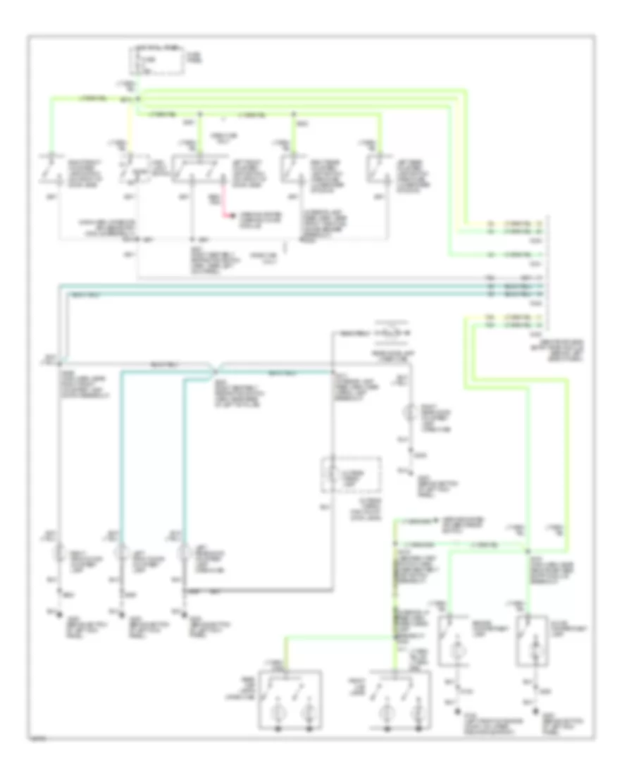
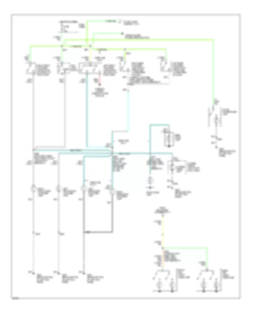
EXTERIOR LIGHTS
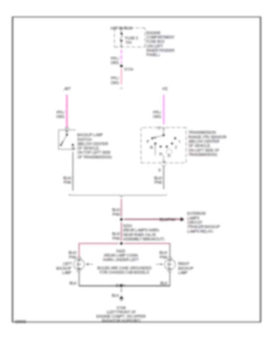
Back-up Lamps Wiring Diagram for Ford F-Super Duty 1997
List of elements for Back-up Lamps Wiring Diagram for Ford F-Super Duty 1997:
- A/t
- Backup
- Backup lamp switch (below center of vehicle, on top left side of transmission)
- Bulbs are case grounded for chassis cab models
- Engine compartment fuse box (on left inner fender panel)
- Exterior lamps circuit (trailer backup lamps relay)
- Fuse 5 15a
- G108 (left front of engine compt, on upper radiator support)
- Hot in run
- Lamp
- Left
- M/t
- Right backup lamp
- S134
- S404
- S426 (rear lamp conn harn, under left
- Transmission range (tr) sensor (below center of vehicle, on left side of transmission)
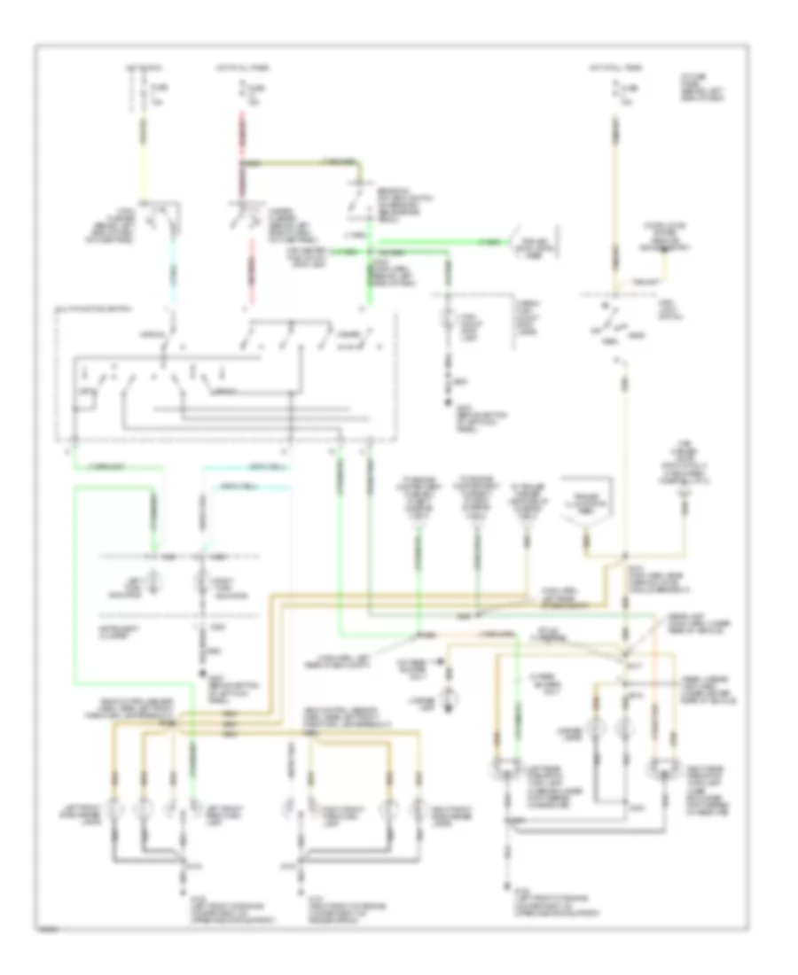
Exterior Lamps Wiring Diagram (1 of 2) for Ford F-Super Duty 1997
List of elements for Exterior Lamps Wiring Diagram (1 of 2) for Ford F-Super Duty 1997:
- (eng control sensor harn, near left front park/turn lamp breakout) s110
- (eng control sensor harn, near left front park/turn lamp breakout) s156
- (if equipped) (diagram 2 of 2)
- (main harn, left rear of eng compt)
- (rear lamp conn harn, under rear of vehicle)
- (rear license lamp harn, under center rear of vehicle)
- Brake on/ off (boo) switch (on bracket, above brake pedal)
- Bumper
- C250
- C251
- Cab marker lamps (pick-up only)
- Cap center high mount stop lamp
- Cargo/ high mount stop lamps
- Door locks system (remote/ keyless entry)
- Fuse 15a
- G101 (right front of engine compartment, on fender apron)
- G108 (left front of engine compartment, on upper radiator support)
- G200 (behind bottom of left kick panel)
- Hazard
- Hazard flasher (behind left side of dash, on fuse panel)
- Head
- High mount stop lamp
- Hot at all times
- Hot in run
- I/p fuse panel (behind left side of dash)
- Instrument cluster
- Left
- Left front park/turn lamp
- Left front side marker lamps
- Left rear park/stop/ turn lamp (case grounded for f-series chassis cab)
- Left turn indicator
- License lamp
- License lamps
- Main light switch
- Multi-function switch
- Normal
- Off
- Only
- Park
- Right
- Right front park/turn lamp
- Right front side marker lamps
- Right rear park/stop/ turn lamp (case grounded for f-series chassis cab)
- Right turn indicator
- S100
- S103
- S200
- S202
- S213 (main harn, near warning chime module breakout)
- S236
- S240 (main harn, behind left side of dash,
- S260
- S261
- S403
- S404
- S417
- S418
- Style/ flare side
- To engine compartment fuse box (fuse 6) (diagram 2 of 2)
- To engine compartment fuse box (fuse 7) (diagram 2 of 2)
- To trailer marker lamps relay (diagram 2 of 2)
- Trailer illumination feed
- Trailer stop lamps feed
- Turn flasher (behind left side of dash, on fuse panel)
- W/ rear
- W/o rear bumper only
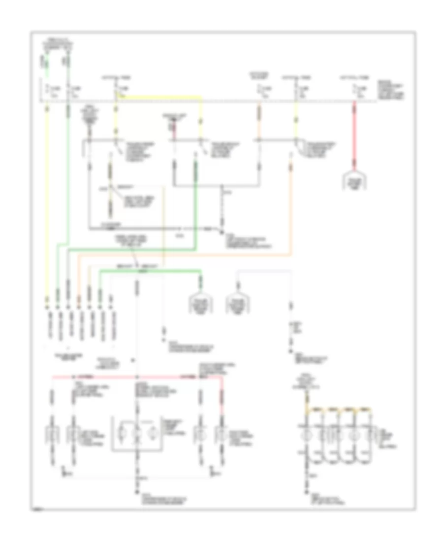
Exterior Lamps Wiring Diagram (2 of 2) for Ford F-Super Duty 1997
List of elements for Exterior Lamps Wiring Diagram (2 of 2) for Ford F-Super Duty 1997:
- (customer use)
- (eng cntrl sens harn, left side of eng compt)
- (rear lamp conn harn, under center rear of vehicle)
- (rear lamps harn, under left rear of vehicle)
- Backup lamp circuit
- Backup lamps
- Battery charge
- Cab marker lamps (if equipped)
- Dual rear
- Electric brakes
- Engine compartment fuse box (on left inner fender panel)
- From main light switch (diagram 1 of 2)
- From multi- function switch (diagram 1 of 2)
- Fuse 10a
- Fuse 15a
- Fuse 25a
- Fuse 30a
- G108 (left front of engine compartment, on upper radiator support)
- G200 (behind bottom of left kick panel)
- G415 (center rear of vehicle, on rear crossmember)
- Hot at all times
- Hot in run or start
- Left side body marker lamps (if equipped)
- Left turn lamp
- Marker lamps
- Nca
- Pick-up w/
- Quarter panel)
- Rear body marker lamps (if equipped)
- Red
- Right side body marker lamps (if equipped)
- Right turn lamp
- S102
- S104
- S109
- S203
- S203 or s205
- S412
- S419
- Trailer backup lamps relay (in trailer relay box)
- Trailer battery charge relay (in trailer relay box)
- Trailer battery feed
- Trailer electric brakes feed
- Trailer ground
- Trailer marker lamps relay (in engine compartment fuse box)
- Trailer/camper adapter
- Wheels only
GROUND DISTRIBUTION
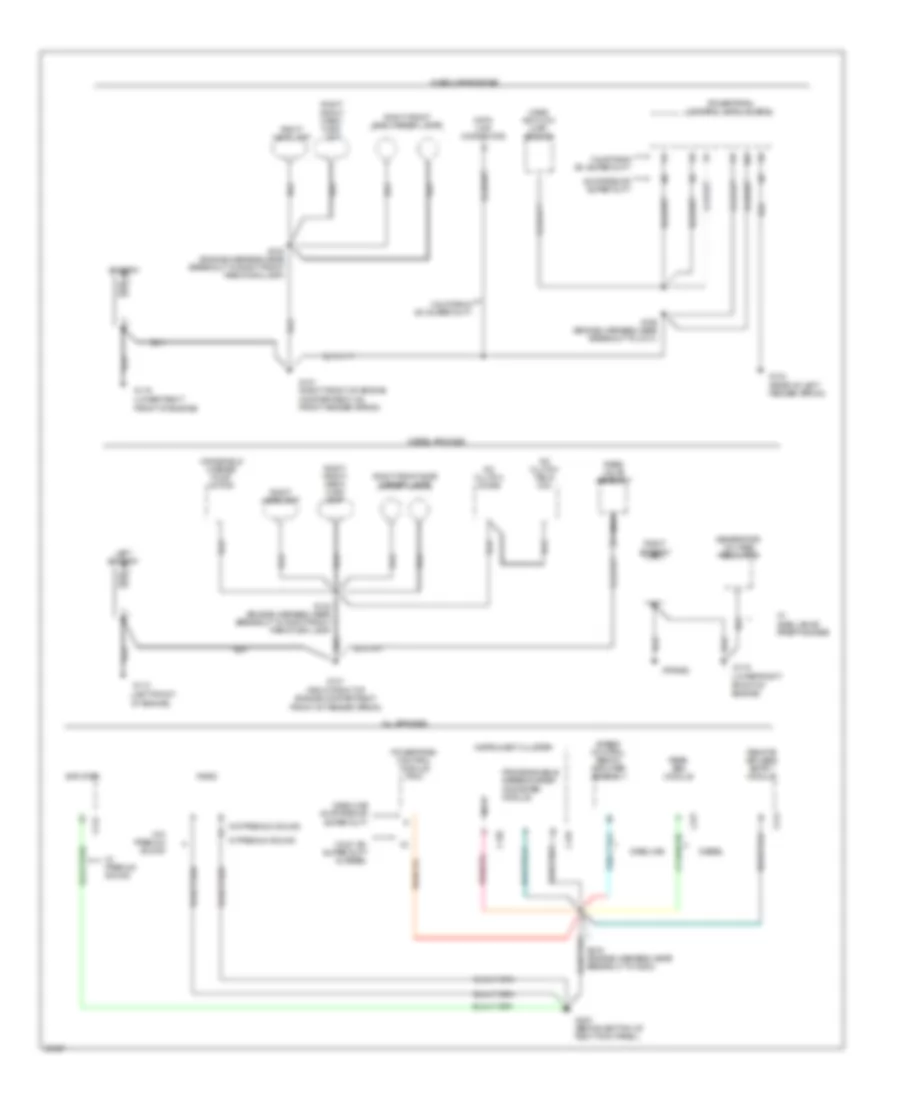
Ground Distribution Wiring Diagram (1 of 4) for Ford F-Super Duty 1997
List of elements for Ground Distribution Wiring Diagram (1 of 4) for Ford F-Super Duty 1997:
- (frame)
- (left front of engine)
- (lower right front of engine)
- 49 states or super duty
- A/c clutch diode
- A/c clutch field coil
- All engines
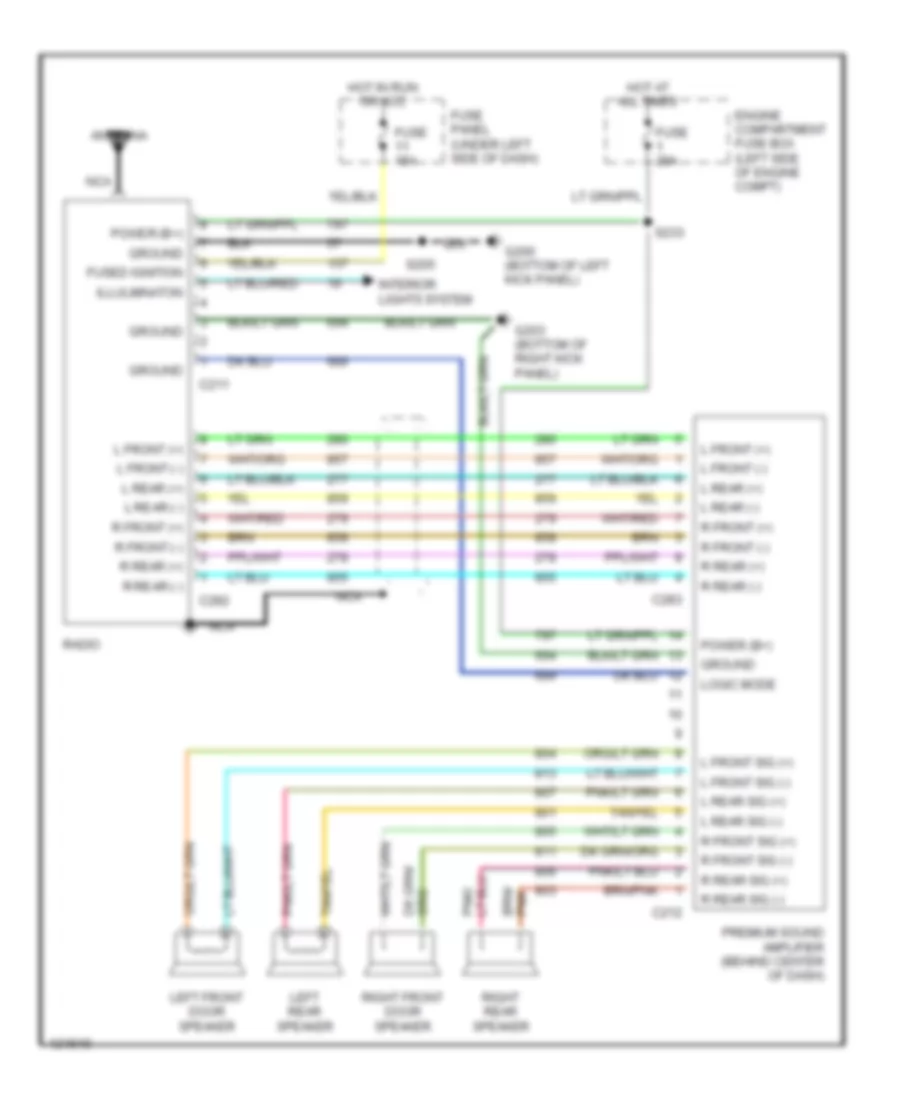
- Amplifier
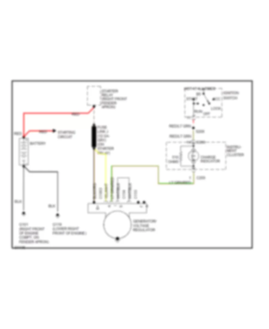
- Battery
- C212
- C241
- C251
- C252
- C277
- Calif. ex. super duty & diesel
- California ex. super duty
- Data link connector
- Diesel
- Diesel engines
- Front of engine)
- G101 (right front of engine compartment, front of fender apron)
- G101 (right front of engine compartment, on front fender apron)
- G104 (rear of left fender apron)
- G110
- G119
- G119 (lower right
- G203 (behind bottom of right kick panel)
- Gasoline
- Gasoline 49 states or super duty
- Gasoline engines
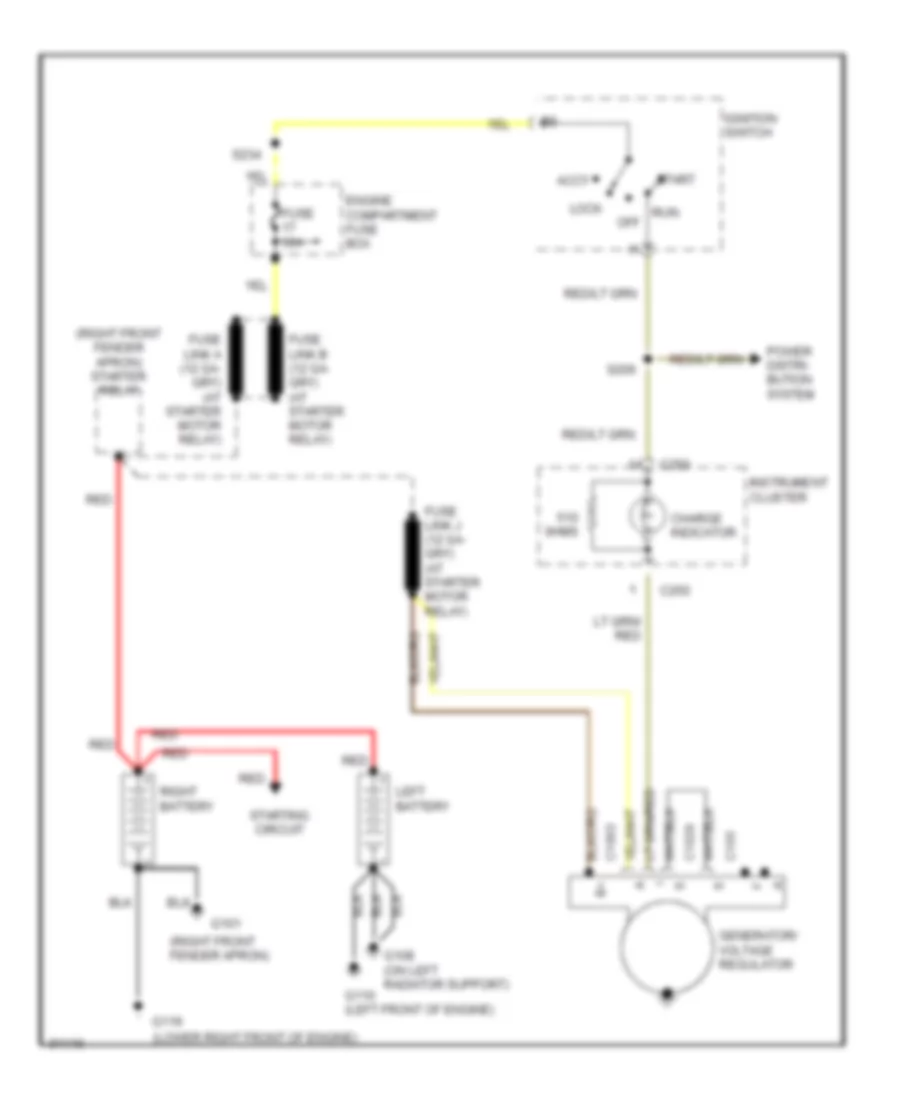
- Generator/ voltage regulator
- Instrument cluster
- Lamp
- Left battery
- Mass air flow (maf) sensor
- Nca
- Powertrain control module (pcm)
- Programmable speedometer/ odometer module
- Rabs valve assembly
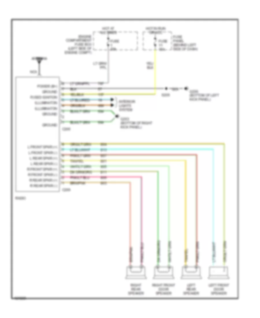
- Radio
- Rear abs module
- Remote keyless entry module
- Right battery
- Right front park/ turn
- Right front park/ turn lamp
- Right front side marker lamps
- Right headlamp
- S100 (engine harness, near breakout to right front park/turn lamp)
- S106 (engine harness, near breakout to g101)
- S216 (engine harness, near breakout to g203)
- Speed control servo/ amplifier assembly
- W/ ambulance prep package
- W/ premium sound
- W/o premium sound
- Windshield washer pump motor
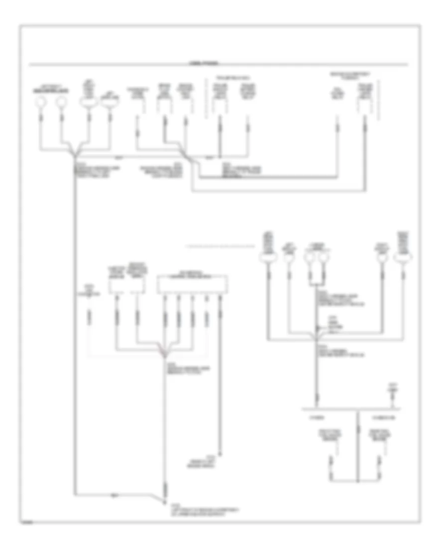
Ground Distribution Wiring Diagram (2 of 4) for Ford F-Super Duty 1997
List of elements for Ground Distribution Wiring Diagram (2 of 4) for Ford F-Super Duty 1997:
- (not
- (rear of left fender apron)
- Brake fluid level switch
- Bumper
- Chassis cab
- Data link connector
- Diesel engines
- Engine compart- ment lamp
- Engine compartment fuse box
- Exhaust pressure regulator (epr)
- Front tank fuel gauge sender
- G104
- G108 (left front of engine compartment, on upper radiator support)
- Injector driver module
- Left backup lamp
- Left front park/ turn lamp
- Left front side marker lamps
- Left headlamp
- Left rear park/ stop/ turn lamp
- License lamps
- Nca
- Only
- Others
- Pcm power relay
- Powertrain control module (pcm)
- Rear
- Rear tank fuel gauge sender
- Right backup lamp
- Right rear park/ stop/ turn lamp
- S101 (engine harness, near breakout to engine compt fuse box)
- S103 (engine harness, near breakout to left front park lamp)
- S104 (body harness, near breakout to trailer relay box)
- S106 (engine harness, near breakout to g108)
- S403 (body harness, near breakout to c400, center rear of vehicle)
- S404 (body harness, center rear of vehicle)
- Trailer backup lamps relay
- Trailer battery charge relay
- Trailer marker lamps relay
- Trailer relay box
- Used)
- Windshield wiper motor
- With
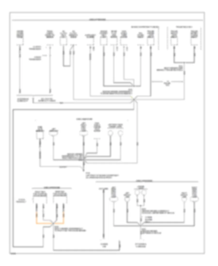
Ground Distribution Wiring Diagram (3 of 4) for Ford F-Super Duty 1997
List of elements for Ground Distribution Wiring Diagram (3 of 4) for Ford F-Super Duty 1997:
- (engine harness, near breakout to left front park/turn lamp) s103
- (left front of engine compartment, on upper radiator support)
- (not used)
- 49 states or super duty
- 5.0l calif. ex. super duty w/e4od
- A/c clutch field coil
- A/c clutch resistor diode
- Brake fluid level switch
- Bumper
- C151
- C170
- C250
- Cab
- Chassis
- Engine compart- ment lamp
- Engine compartment fuse box
- Flare side
- Front tank fuel pump/fuel gauge sender
- G108
- Gasoline engines
- Heated oxygen sensor (ho2s)
- Instrument cluster
- Left backup lamp
- Left front park/ turn lamp
- Left front side marker lamps
- Left headlamp
- Left rear park/ stop/ turn lamp
- License lamps
- Nca
- Only
- Pcm power relay
- Rabs valve assembly
- Rear tank fuel pump/fuel gauge sender
- Right backup lamp
- Right rear park/ stop/ turn lamp
- S102 (engine harness, near breakout to brake resistor/diode assembly)
- S104 (body harness, near breakout trailer relay box)
- S400 (body harness, near breakout to front fuel tank gauge sender)
- S403 (engine harness, in breakout conn c400, center rear of vehicle)
- S404 (engine harness, left rear of vehicle)
- Style side &
- Tanks only
- Tow
- Trailer
- Trailer backup lamps relay
- Trailer battery charge relay
- Trailer relay box
- Trailer/ marker lamps relay
- Trans- mission range (tr) sensor
- Transmission
- W/ 4r70w
- W/ dual
- W/ e4od
- W/ rear
- Wind- shield washer pump motor
- Wind- shield wiper motor
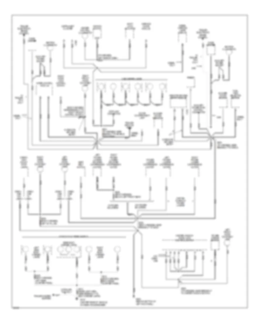
Ground Distribution Wiring Diagram (4 of 4) for Ford F-Super Duty 1997
List of elements for Ground Distribution Wiring Diagram (4 of 4) for Ford F-Super Duty 1997:
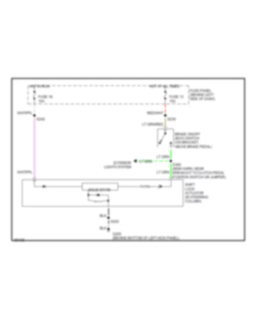
- (behind bottom of left kick panel)
- (body harness, near breakout to right window control switch) s602
- (center rear of vehicle, on rear crossmember)
- (i/p harness, left side of dash) s202
- Ashtray illumination
- Auxiliary power socket
- Auxiliary powertrain control connector
- Blower motor resistor
- Blower motor switch
- C242
- C250
- Cab marker lamps
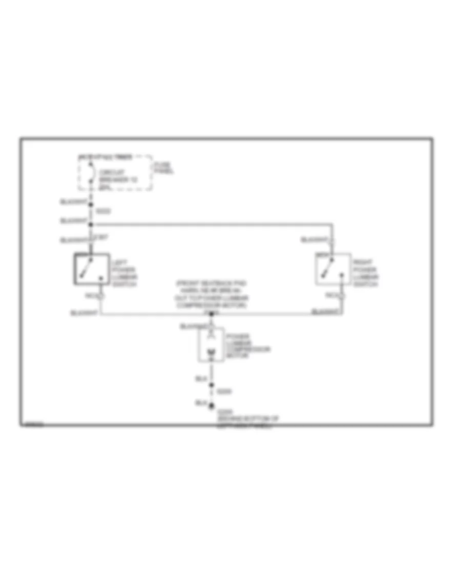
- Captain chairs w/ power lumbar
- Cargo/ high mount stop lamps
- Cigar lighter
- Crew cab w/ xlt
- Crew cab w/o xlt
- Data link connector
- Diesel only
- Diesel warning lamps display
- F-350 w/ dual rear wheels
- Fuel tank selector switch
- G200
- G415
- Gas
- Glove compartment lamp
- Gnd
- Heater control illumination
- Ignition switch
- Instrument cluster
- Left front door courtesy lamp
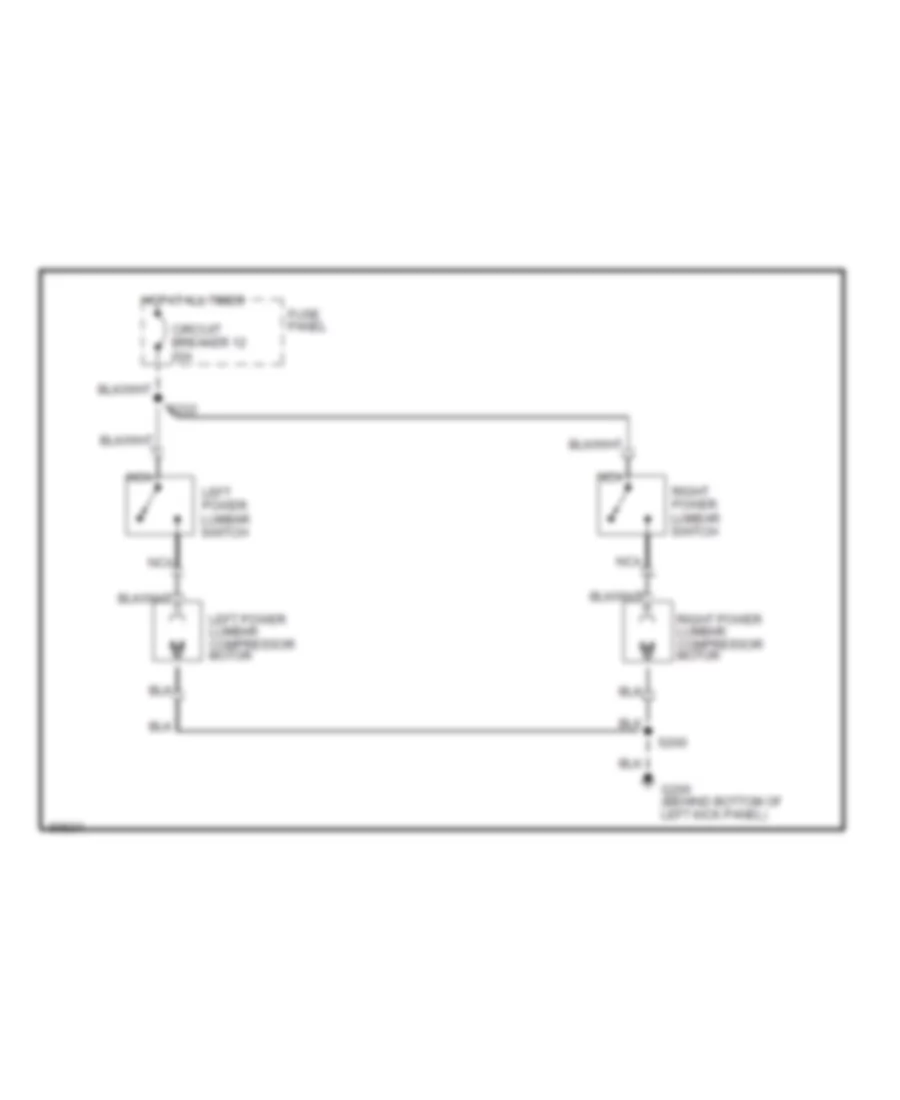
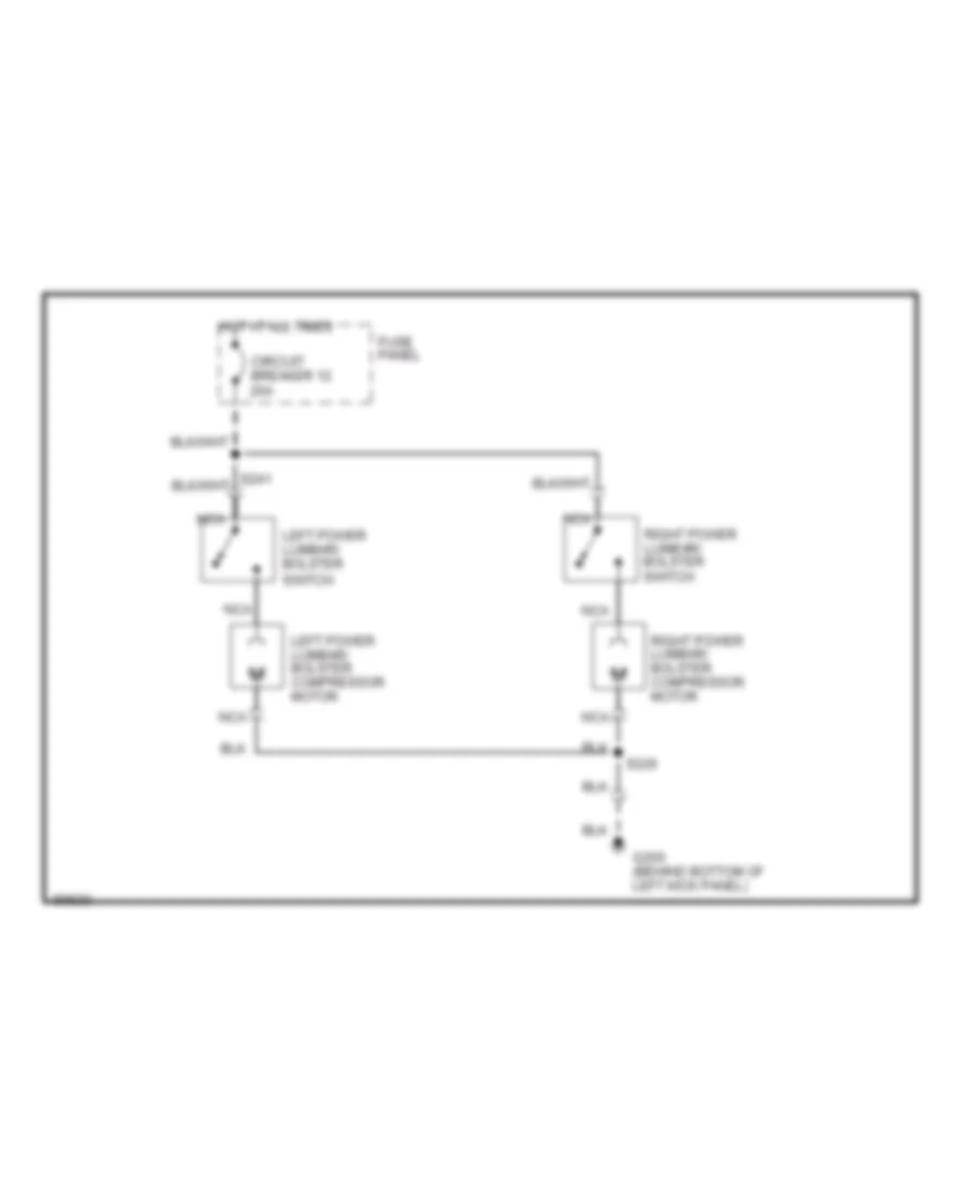
- Left power lumbar compressor motor
- Left power lumbar/ bolster compressor motor
- Left rear door courtesy lamp
- Left side body marker lamps
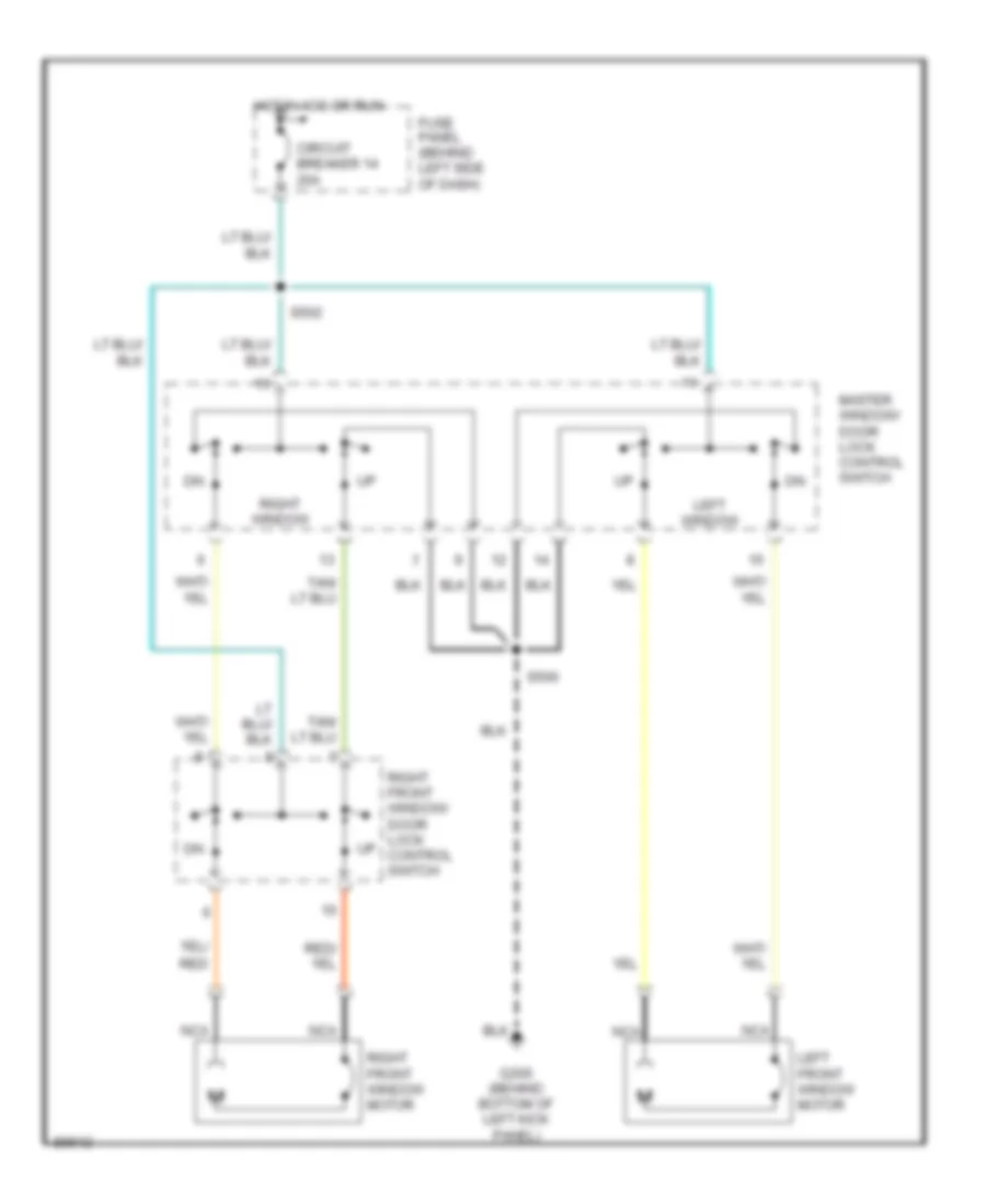
- Master window/ door lock control switch
- Nca
- Power lumbar compressor motor
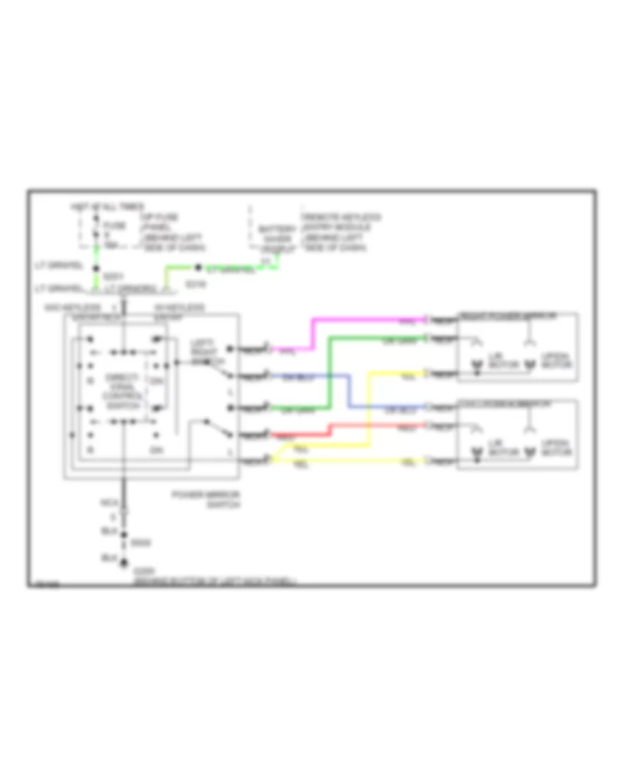
- Power mirror switch
- Radio
- Rear body marker lamps
- Remote keyless entry module
- Right door lock control switch
- Right front door courtesy lamp
- Right power lumbar compressor motor
- Right power lumbar/ bolster compressor motor
- Right rear door courtesy lamp
- Right side body marker lamps
- S200 (body harness, near breakout to g200)
- S203 (i/p harness, near breakout to enable psom conn)
- S205 (i/p harness, near breakout to radio)
- S226 (body harness, below left front seat)
- S309 (body harness, left "b" pillar)
- S409 (body harness, left rear quarter panel)
- S412 (rear lamp harn, near breakout to body marker lamps)
- S500 (i/p harness, near breakout to master window switch)
- Seat belt switch
- Shift lock actuator
- Trailer electronic brake control
- Trailer ground feed
- Trailer/camper adapter
- W/ power bolsters
- W/ remote keyless entry
- W/ trailer tow only
- W/o crew cab
- W/o power bolsters
- W/trailer tow only
- Warning chime module
- Wiper control module
HEADLIGHTS
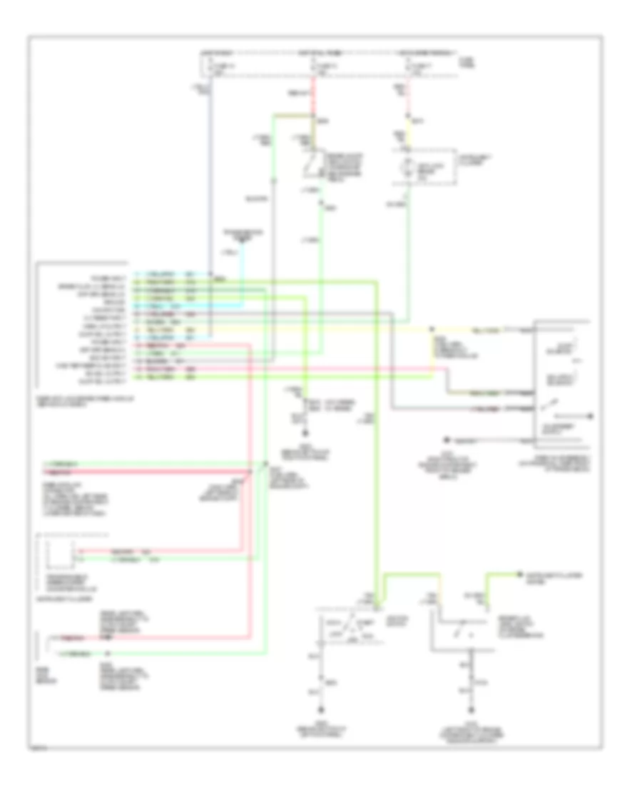
Headlight Wiring Diagram, with DRL for Ford F-Super Duty 1997
List of elements for Headlight Wiring Diagram, with DRL for Ford F-Super Duty 1997:
- (eng control sensor harn, near left headlamp breakout) s154
- (not used)
- 40a
- Acc
- Battery power
- Brake fluid level switch (left rear of engine compartment, on brake fluid reservoir)
- Brake warn in
- Brake warning indicator
- C250
- C251
- Daytime running lamps (drl) module (front left side of lower radiator support)
- Diesel only
- Dimmer
- Engine compartment fuse box (left side of engine compartment, on top of front wheelwell)
- Engine controls system
- Flash-to- pass
- Fuse 17 10a
- Fuse 19
- Fuse 3 30a
- Fuse 5 15a
- Fuse panel (behind lower left side of i/p, left of steering column)
- G101 (right front of engine compartment, on fender apron)
- G108 (left front of engine compartment, on upper radiator support)
- G200 (behind bottom of left cowl panel)
- G200 (behind bottom of left kick panel)
- Gnd
- Head
- Hi beam indicator
- Hi headlamp
- High beam ind
- Hot at all times
- Hot in run
- Hot in start or run
- Ignition switch
- Instrument cluster
- Instrument cluster system
- Left headlamp
- Lo headlamp
- Lock
- Main light switch
- Multi- function switch
- Off
- Park
- Park brake sw in
- Park brake switch (behind left side of i/p, top of park brake pedal)
- Pass
- Power (hot in run)
- Right headlamp
- Run
- S100
- S102
- S103
- S105
- S115
- S140
- S155 (eng control sensor harn, near left front of eng compartment)
- S202
- S215
- Start
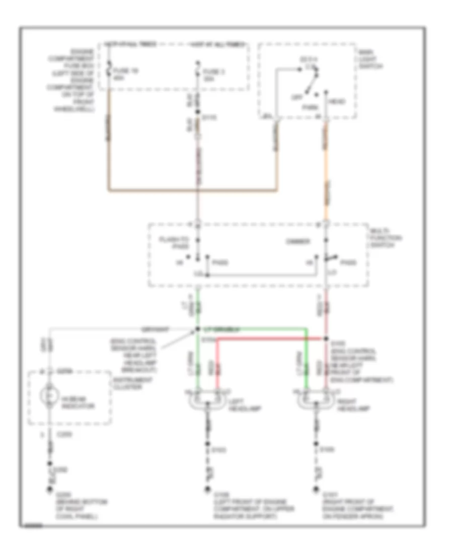
Headlight Wiring Diagram, without DRL for Ford F-Super Duty 1997
List of elements for Headlight Wiring Diagram, without DRL for Ford F-Super Duty 1997:
- (eng control sensor harn, near left headlamp breakout)
- 22.5 a c.b.
- C250
- Dimmer
- Engine compartment fuse box (left side of engine compartment, on top of front wheelwell)
- Flash-to -pass
- Fuse 19 40a
- Fuse 3 30a
- G101 (right front of engine compartment, on fender apron)
- G108 (left front of engine compartment, on upper radiator support)
- G200 (behind bottom of right cowl panel)
- Head
- Hi beam indicator
- Hot at all times
- Instrument cluster
- Left headlamp
- Main light switch
- Multi- function switch
- Off
- Park
- Pass
- Right headlamp
- S100
- S103
- S115
- S154
- S155 (eng control sensor harn, near left front of eng compartment)
- S202
HORN
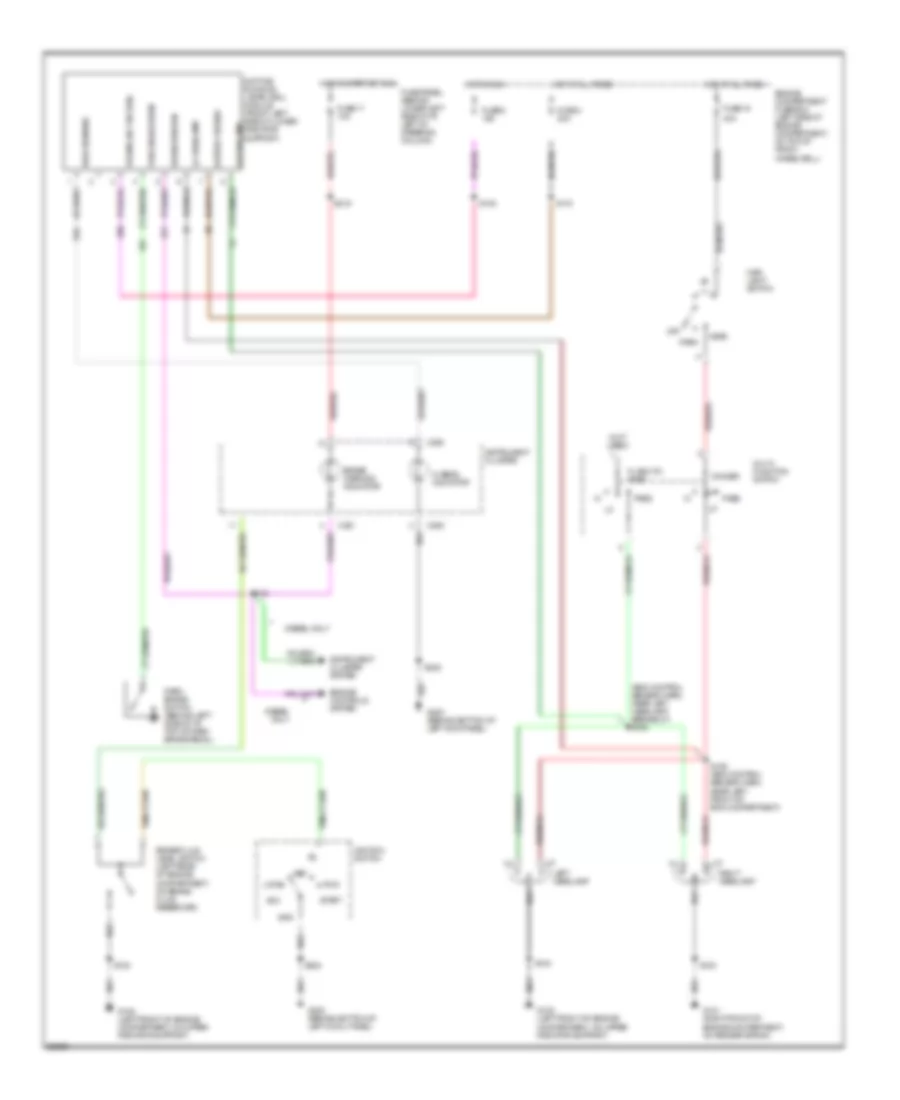
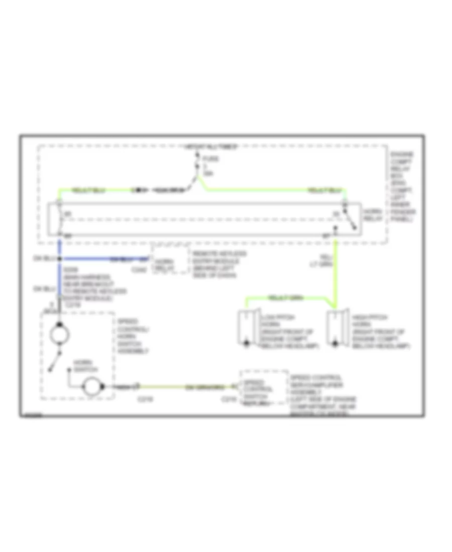
Horn Wiring Diagram for Ford F-Super Duty 1997
List of elements for Horn Wiring Diagram for Ford F-Super Duty 1997:
- C219
- C242
- Engine compt relay box (eng compt, left inner fender panel)
- Fuse 30a
- High pitch horn (right front of engine compt, below headlamp)
- Horn relay
- Horn switch
- Hot at all times
- Low pitch horn (right front of engine compt, below headlamp)
- Nca
- Remote keyless entry module (behind left side of dash)
- Return
- S115
- S208 (main harness, near breakout to remote keyless entry module)
- Speed control servo/amplifier assembly (left side of engine compartment, near master cylinder)
- Speed control switch c216
- Speed control/ horn switch assembly
INSTRUMENT CLUSTER
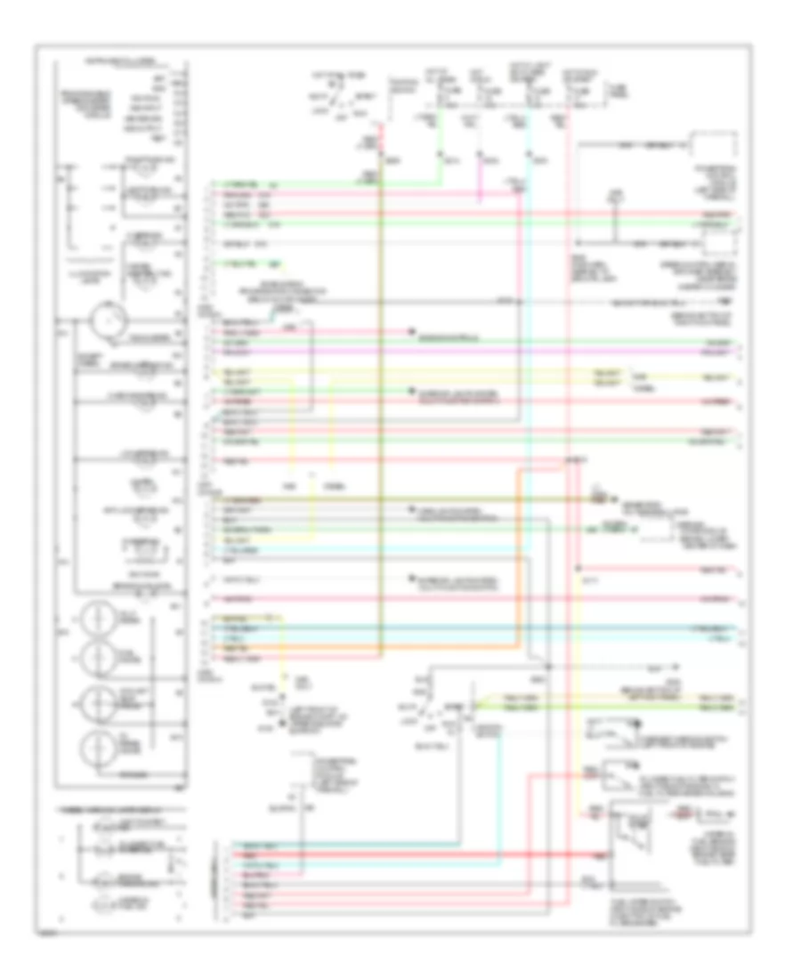
Instrument Cluster Wiring Diagram (1 of 2) for Ford F-Super Duty 1997
List of elements for Instrument Cluster Wiring Diagram (1 of 2) for Ford F-Super Duty 1997:
- (behind bottom of right kick panel)
- (behind lower
- (left front of engine compt, on upper radiator support)
- 20 ohms
- 4x4 ind.
- 500 ohms
- A10
- A11
- A12
- A13
- A14
- Acc
- Anti-lock brake ind.
- B10
- B11
- B13
- Bat
- Brake fluid level
- Brake warning ind.
- C250 conn a
- C251 conn b
- C252 conn c
- Center of dash)
- Charge ind.
- Check engine ind.
- Chime module
- Coolant temp. gauge
- Diesel
- Diesel only
- Diesel warning lamps display
- Enable psom programming connector (below glove compt)
- Engine controls
- Engine warning ind.
- Except diesel
- Exterior lights system (multi-function switch)
- Fasten seat belt ind.
- Fuel gauge
- Fuel water switch (right side of engine, on bottom of fuel filter/heater)
- Fuse 10a
- Fuse 15a
- Fuse 4a
- Fuse panel
- G108
- G200 (behind bottom of left kick panel)
- G203
- Gas
- Gas only
- Generator/ voltage regulator
- Gnd
- Headlights system (multi-function switch)
- Hi beam ind.
- Hot at all times
- Hot in run
- Hot in run or start
- Hot w/ light sw in head or park
- Ign (run)
- Ignition switch
- Illumination lamps
- Instrument cluster
- Left turn ind.
- Lock
- Low range ind.
- Off
- Oil press. gauge
- Overheat warning switch (left front of engine)
- Plugged fuel filter ind.
- Plugged fuel filter switch (right side of engine, in fuel filter/heater housing)
- Powertrain control module (left side of firewall)
- Programmable speedometer/ odometer module
- Red
- Red/pnk
- Right turn ind.
- Run
- S102
- S117
- S202
- S206
- S214
- S215
- S216
- S218
- S242
- S246 (main harn, near b/o to spd ctrl amp)
- Solid state
- Speed control servo/ amplifier assembly (near brake master cylinder)
- Start
- Tachometer
- Test
- Volt- meter
- Vss input
- Vss output
- Vss return
- Wait-to-start ind.
- Warning
- Water-in- fuel ind.
- Water-in- fuel sensor (right side of engine, near fuel filter)
Instrument Cluster Wiring Diagram (2 of 2) for Ford F-Super Duty 1997
List of elements for Instrument Cluster Wiring Diagram (2 of 2) for Ford F-Super Duty 1997:
- (below right center of
- (below right rear of
- (left rear of engine
- 4x2
- 4x4
- 4x4 hi/low indicator switch (below vehicle, on front of transfer case)
- Brake fluid level switch (left rear of engine compt, on brake fluid reservoir)
- Compt, on bracket)
- Daytime running lamps module (on radiator support)
- Diesel
- Diesel only
- Engine coolant temperature sender (top left front of engine)
- Engine oil pressure switch (5.8l-lower left front of engine, near oil filter) (7.3l & 7.5l-top center rear of engine)
- Front
- Front tank fuel gauge sender
- Front tank fuel pump/ fuel gauge sender (below right center of vehicle, in front fuel tank)
- Fuel tank selector switch
- Fuel tank selector valve (under left center of vehicle, on left frame rail)
- Fuse 6 15a
- Fuse panel
- G108 (left front of engine compartment, on upper radiator support)
- G200 (bottom of left kick panel)
- Gas
- Gasoline
- Hot in acc or run
- Ignition coil (left rear of engine, near intake manifold)
- Ignition control module (left side of inner fender panel)
- Link connector
- Low
- Low vacuum warning switch (diesel only) (left side of engine compt, behind battery)
- Nca
- Only
- Park brake switch
- Power- train control module (left side of firewall)
- Powertrain control module (left side of firewall)
- Powertrain control module (left side of firewall)
- Rabs data
- Rear
- Rear anti-lock brake module (behind glove box)
- Rear axle speed sensor (on axle assembly)
- Rear tank fuel gauge sender
- Rear tank fuel pump/ fuel gauge sender (below right rear of vehicle, in rear fuel tank)
- Red
- Red/
- Red/ pnk
- Red/pnk
- S140
- S171 (engine harn, near distributor)
- S174 (engine harn, near brake resistor/diode assembly)
- S202
- S205
- S229
- S244 (main harn, center of dash)
- S247 (main harn, left rear of eng compt)
- S248 (main harn, left rear of eng compt)
- S400
- Solid state
- Vehicle, in front fuel tank)
- Vehicle, in rear fuel tank)
- W/ drl
- W/o drl
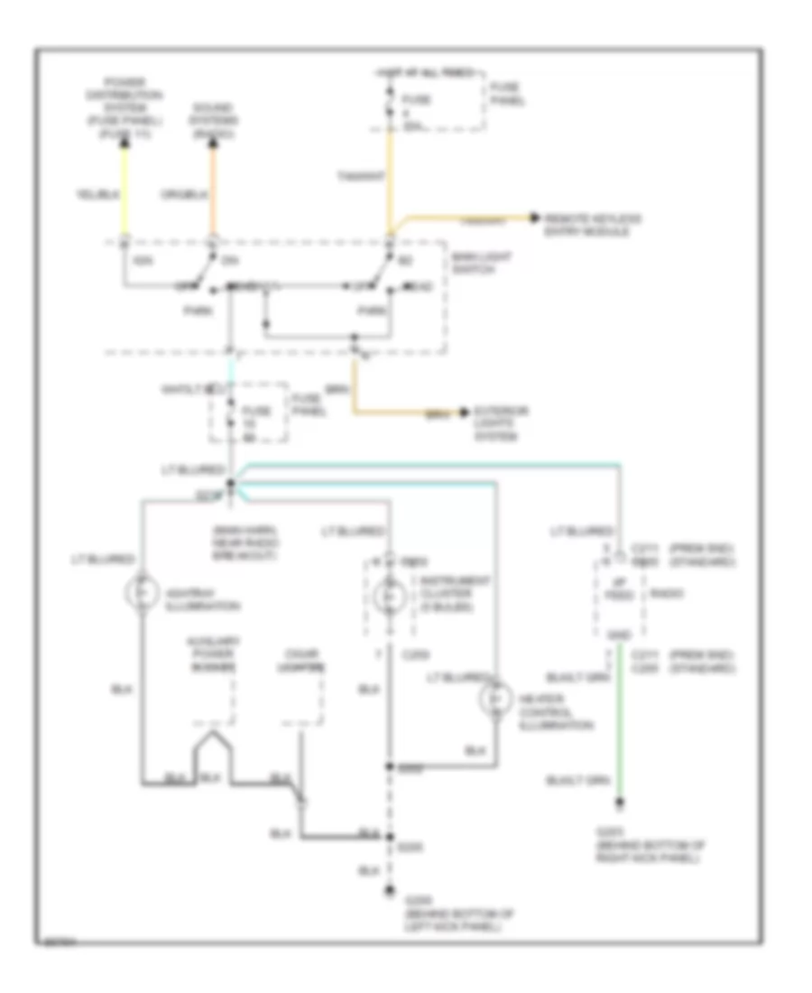
INTERIOR LIGHTS
Courtesy Lamps Wiring Diagram, with Keyless Entry for Ford F-Super Duty 1997
List of elements for Courtesy Lamps Wiring Diagram, with Keyless Entry for Ford F-Super Duty 1997:
- (crew-cab)
- (interior lamp feed harn, near front tank fuel gauge sender breakout) s324
- (interior lp feed harn, near cargo lamp breakout) s322
- (main harn, in remote keyless entry module breakout) s212
- C240
- C241
- C242
- Crew cab only
- Dome
- Engine compartment lamp
- Front map lamps
- Fuse 15a
- Fuse panel
- G108 (left front of engine compt, on upper radiator support)
- G200 (behind bottom of left kick panel)
- Glove compartment lamp
- Hot at all times
- Left front courtesy lamp switch (on front of door jamb)
- Left front door courtesy lamp
- Left rear courtesy lamp switch (crew-cab) (lower rear of door)
- Left rear door courtesy lamp (crew-cab)
- Main light switch
- Mirrors system (power mirror switch)
- Outside cargo lamp
- Outside cargo/ high mount stop lamps
- Rear dome lamp (crew-cab)
- Rear map lamps
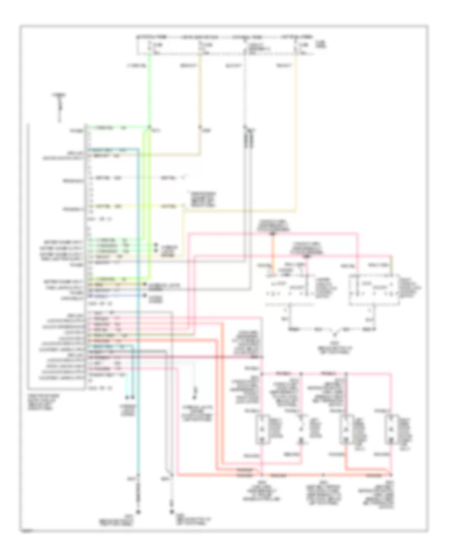
- Red/ pnk
- Remote keyless entry (rke) module (behind left side of dash)
- Right front courtesy lamp switch (on front of door jamb)
- Right front door courtesy lamp
- Right rear courtesy lamp switch (crew-cab) (lower rear of door)
- Right rear door courtesy lamp (crew-cab)
- S102
- S203
- S214
- S221 (right seat belt retractor switch harn, near left kick panel)
- S251
- S299 (main harn, near right front courtesy lamp switch breakout)
- S305 (right seat belt retractor switch harn, near base of left "b" pillar)
- S309
- S315 (main harn, near remote keyless entry module breakout)
- S316 (seat belt ret switch harn, near seat belt ret switch breakout)
- S317 (interior lamp feed harn, near cargo lamp breakout)
- S323
- S500
- S602
- Warning system (warning chime module)
Courtesy Lamps Wiring Diagram, without Keyless Entry for Ford F-Super Duty 1997
List of elements for Courtesy Lamps Wiring Diagram, without Keyless Entry for Ford F-Super Duty 1997:
- (crew-cab)
- (interior lamp feed harn, near right rear courtesy lamp sw breakout) s324
- Breakout)
- Crew cab only
- Crew cab w/ xlt
- Dome
- From splice s251 (diagram 1 of 1)
- Front dome lamp
- Front map lamps
- Fuse 15a
- Fuse panel
- G200 (behind bottom of left kick panel)
- Glove compartment lamp
- Hot at all times
- Left front courtesy lamp switch (on front of door jamb)
- Left front door courtesy lamp
- Left rear courtesy lamp switch (crew-cab) (lower rear of door)
- Left rear door courtesy lamp
- Main light switch
- Mirror system (power mirror switch)
- Outside cargo lamp
- Outside cargo/ high mount stop lamps
- Rear dome lamp
- Rear map lamps (crew-cab)
- Red/ pnk
- Right front courtesy lamp switch (on front of door jamb)
- Right front door courtesy lamp
- Right rear courtesy lamp switch (crew-cab) (lower rear of door)
- Right rear door courtesy lamp
- S200
- S203
- S214
- S251
- S305 (right seat belt ret switch harn, near base of left "b" pillar)
- S309
- S322 (interior lamp feed harn, near cargo lamp breakout)
- S323
- S500
- To map lamps (diagram 1 of 1)
- Warning system (warning chime module)
Instrument Illumination Wiring Diagram for Ford F-Super Duty 1997
List of elements for Instrument Illumination Wiring Diagram for Ford F-Super Duty 1997:
- (main harn, near radio breakout)
- (prem snd)
- (standard)
- Ashtray illumination
- Auxiliary power socket
- C211
- C250
- C265
- Cigar lighter
- Exterior lights system
- Fuse 15a
- Fuse 4a
- Fuse panel
- G200 (behind bottom of left kick panel)
- G203 (behind bottom of right kick panel)
- Gnd
- Head
- Heater control illumination
- Hot at all times
- I/p feed
- Ign
- Instrument cluster (5 bulbs)
- Main light switch
- Off
- Park
- Power distribution system (fuse panel) (fuse 11)
- Radio
- Remote keyless entry module
- S202
- S205
- S218
- Sound systems (radio)
POWER DISTRIBUTION
Power Distribution Wiring Diagram (1 of 3) for Ford F-Super Duty 1997
List of elements for Power Distribution Wiring Diagram (1 of 3) for Ford F-Super Duty 1997:
- (behind bottom of left kick panel)
- (body harness, near breakout to conn c500, left front window motor) s502
- (diesel)
- (ex. premium sound)
- (gas)
- (i/p harness, near breakout to blower motor switch) s229
- (i/p harness, near breakout to fuse panel) s211
- (i/p harness, near breakout to fuse panel) s217
- (i/p harness, near breakout to fuse panel) s242
- (i/p harness, near breakout to wiper control module) s238
- (premium sound)
- 200a generator/ voltage regulator
- A/c-heater control assembly
- Acc
- Auxiliary powertrain control connector
- C1029
- C153
- C154
- Circuit breaker 14 20a
- Clutch pedal position switch
- Diesel only
- Diesel warning lamps display
- Diesel with 200 amp generator
- Engine compartment fuse box
- Fuel tank selector switch
- Fuse 10a
- Fuse 15a
- Fuse 20a
- Fuse 25a
- Fuse 30a
- Fuse 50a
- Fuse panel (left side of i/p)
- G200
- Generator/ voltage regulator
- Glow plug relay
- Gnd
- Heater control assembly
- Heater or a/c-heater control module
- Ign
- Ignition switch
- Instrument cluster
- Instrument cluster system
- Left battery (diesel only)
- Left side of safety wall)
- Lock
- Main light switch
- Master window/ door lock control switch
- Mega fuse 300a (diesel only)
- Off
- Programmable speedometer/ odometer module
- Radio
- Rear anti-lock brake (rabs) module
- Red
- Remote keyless entry module
- Right battery
- Right window/ door lock control switch
- Run
- S202
- Shift lock actuator
- Sta
- Start
- Starter relay
- Starter solenoid
- Starting/charging system (clutch pedal position switch)
- To engine compartment fuse box (fuse 22) (diagram 2 of 3)
- To engine compartment fuse box (fuse 5) (diagram 2 of 3)
- To engine compartment fuse box (fuse 9) (diagram 2 of 3)
- Trailer backup lamp relay
- Trailer battery charge relay
- Trailer relay box
- Trailer/ marker lamps relay
- Turn flasher
- W/ a/c
- W/ trailer tow
- W/o a/c
- Windshield wiper motor
- Wiper control module
Power Distribution Wiring Diagram (2 of 3) for Ford F-Super Duty 1997
List of elements for Power Distribution Wiring Diagram (2 of 3) for Ford F-Super Duty 1997:
- (49 states or super duty)
- (calif. ex. super duty, diesel)
- (e4od transmission)
- (engine harness, near breakout to engine compt fuse box) s105
- (engine harness, near breakout to ignition coil) s199
- (not used)
- (s5-42 zf transmission)
- 200 a generator/ voltage regulator
- Backup lamp switch
- Brake pressure switch
- C250
- C251
- Cruise control servo/amplifier assembly
- Daytime running lamp (drl) module
- Diesel only
- Diesel only (i/p harness, near breakout to conn c251, left side of i/p) s215
- Diesel warning lamps display
- Distributor
- Engine comparment fuse box
- Engine compartment fuse box
- From engine compartment fuse box (fuse 17) (diagram 1 of 3)
- From ignition b switch (diagram 1 of 3)
- From ignition switch (diagram 1 of 3)
- Fuel line heater
- Fuel pump relay
- Fuel water switch
- Fuse 10a
- Fuse 15a
- Fuse 20a
- Fuse 3 3a
- Fuse 30a
- Fuse panel (left side of i/p)
- Gas only
- Gasoline only
- Glow plug relay
- Heated oxygen sensor (ho2s)
- Idle validation switch (diesel only)
- Ignition coil
- Ignition control module
- Injector driver module (idm) relay (diesel only)
- Instrument cluster
- Low vacuum warning switch
- Nca
- Pcm power diode
- Pcm power relay
- Power- train control module
- Radio capacitor
- Red/
- S114 (engine harness, near breakout to brake warning resistor)
- S117 (engine harness, near breakout to left headlamp)
- S128 (engine harness, in breakout to fuel line heater)
- S134 (engine harness, near breakout to back-up lamp switch)
- S134 (engine harness, near breakout to transmission range sensor)
- S148 (engine harness, near breakout to brake warning resistor)
- S206 (i/p harness, near breakout to fuse panel)
- To engine compartment fuse box (fuse 13) (diagram 3 of 3)
- Trailer battery charge relay
- Trailer relay box
- Trans- mission control switch
- Transmission range (tr) sensor
- W/ diesel engine
- W/ e40d transmission
- W/ gasoline engine
- W/ manual transmission
- Warning chime module
- With electronic shift only
Power Distribution Wiring Diagram (3 of 3) for Ford F-Super Duty 1997
List of elements for Power Distribution Wiring Diagram (3 of 3) for Ford F-Super Duty 1997:
- (behind bottom of left kick panel)
- (body harness, near breakout to cargo lamp) s322
- (body harness, near breakout to conn c214, left kick panel) s501
- (body harness, near breakout to conn c300, left "b" pillar)
- (diagram 2 of 3)
- (i/p harness, near breakout to fuse box) s236
- (i/p harness, near premium sound amplifier) s233
- (premium sound)
- (reg cab)
- (super cab)
- 5a * 10a **
- Auxiliary power socket
- Brake on/off (boo) switch
- Brake pressure switch
- C240
- C241
- Circuit breaker 12 20a
- Crew cab
- Data link connector
- Daytime running lamp (drl) module
- Engine compart- ment lamp
- Engine compartment fuse box
- Ex. calif. * super duty
- Exterior lights system (multi-function switch)
- From engine compartment d fuse box (fuse 16)
- Front map lamps
- Fuse
- Fuse 10a
- Fuse 15a
- Fuse 20a
- Fuse 25a
- Fuse 30a
- Fuse 40a
- Fuse 4a
- Fuse 50a
- Fuse panel (left side of dash)
- G200
- Gasoline
- Gasoline only
- Glove compart- ment lamp
- Hazard flasher
- Horn relay
- Instrument cluster
- Interior lights system
- Interior lights system (main light switch)
- Left front courtesy lamp switch
- Left power lumbar switch
- Left power lumbar/ bolster switch
- Lighter
- Main light switch
- Master window/ door lock control switch
- Multi- function switch
- Nca
- Others **
- Power mirror switch
- Premium sound ampli- fier
- Premium sound only
- Program- mable speedo- meter/ odometer module
- Radio
- Rear anti- lock brake (rabs) module
- Rear map lamps
- Red
- Remote keyless entry module
- Remote keyless entry module
- Right front courtesy lamp switch
- Right power lumbar switch
- Right power lumbar/ bolster switch
- Right window/ door lock control switch
- S115 (engine harness, near breakout to left headlamp)
- S214 (i/p harness, near breakout to warning chime module)
- S222 (body harness, near breakout to g201)
- S237 (body harness, near breakout to brake on/off switch)
- S241
- S251 (body harness, near breakout to conn c300, left "b" pillar)
- S259 (engine harness, near breakout to conn c202, left side of safety wall)
- S307 (body harness, near breakout to power lumbar compressor motor)
- To trailer electronic brake control unit
- To trailer left turn lamps
- To trailer right turn lamps
- Trailer provision
- Trailer provisions
- W/o remote keyless entry
- W/o rke
- With captain's chair
- With cloth bench
- With power bolster
- With power lumbar seats
- With remote keyless entry
- With remote keyless entry only
POWER DOOR LOCKS
Door Lock Wiring Diagram for Ford F-Super Duty 1997
List of elements for Door Lock Wiring Diagram for Ford F-Super Duty 1997:
- (seat belt sw harn, near breakout to seat belt sw) (w/ crew cab) s312
- (window reg left door harn, near breakout to 8 pin conn, behind left kick panel)
- (window reg right door harn, near breakout to right front windw mtr)
- (window reg right door harn, near breakout to right windw ctrl sw)
- Circuit breaker 12 20a
- Fuse panel
- G200 (behind bottom of left kick panel)
- Hot at all times
- Left front door lock motor
- Left rear door lock motor
- Lock
- Master window/ door lock control switch
- Pnk/
- Right front door lock motor
- Right rear door lock motor
- Right window/ door lock control switch
- S222
- S225 (rear lamp harn, near breakout to 24 pin conn, in firewall)
- S256
- S500
- S501
- S600
- S601
- Unlock
- W/ crew cab
Keyless Entry Wiring Diagram for Ford F-Super Duty 1997
List of elements for Keyless Entry Wiring Diagram for Ford F-Super Duty 1997:
- (behind bottom of left kick panel)
- (behind bottom of right kick panel)
- (main harn, near break- out to enable psom prog conn, below glove compt) s303
- (window harn, near breakout to door speaker) s301
- (window harn, near breakout to door speaker) s302
- Antenna
- Battery saver input
- Battery saver output
- C240
- C241
- C242
- Circuit breaker 12 20a
- Courtesy lamps output
- Crtsy lamp sw input
- Exterior lights system
- Fuse 15a
- Fuse panel
- G200
- G200 (behind bottom of left kick panel)
- G203
- Ground
- Horn relay
- Horns system
- Hot at all times
- Hot in accy or run
- Ignition switch input
- Interior lights system
- Interior lights system (door courtesy lamp switches)
- Left front door lock motor
- Left rear door lock motor (crew cab only)
- Lock
- Lock doors output
- Lock input
- Master window/ door lock control switch
- Nca
- Park lamps output
- Power
- Program a
- Program b
- Remote keyless entry module (behind left side of dash)
- Right front door lock motor
- Right rear door lock motor (crew cab only)
- Right window/ door lock control switch
- Rke program connector (behind left side of dash)
- S205
- S214
- S216
- S223 (seat belt retrac- tor switch harn, near breakout to 8 pin conn, behind left kick panel)
- S229
- S237
- S304 (window right door harn, near breakout to right front door lock motor)
- S306 (main harn, near breakout to trailer brake controller)
- S318 (window left door harn, near breakout to 6 pin conn, behind left kick panel)
- S319 (seat belt retractor switch harn, near breakout seat belt retractor switch)
- S320 (seat belt retractor switch harn, near breakout seat belt retractor switch)
- S500
- S602
- Unlock
- Unlock doors output
- Unlock driver's door
- Unlock input
- W/crew cab
POWER MIRRORS
Power Mirror Wiring Diagram for Ford F-Super Duty 1997
List of elements for Power Mirror Wiring Diagram for Ford F-Super Duty 1997:
- Battery saver output
- Direct- ional control switch
- Fuse 15a
- G200 (behind bottom of left kick panel)
- Hot at all times
- I/p fuse panel (behind left side of dash)
- L/r motor
- Left power mirror nca
- Left/ right switch
- Nca
- Nca entry
- Power mirror switch
- Red
- Remote keyless entry module (behind left side of dash)
- Right power mirror nca
- S251
- S316
- S500
- Up/dn motor
- W/ keyless entry
- W/o keyless
POWER SEATS
Lumbar Wiring Diagram, with Captain's Chairs for Ford F-Super Duty 1997
List of elements for Lumbar Wiring Diagram, with Captain's Chairs for Ford F-Super Duty 1997:
- Circuit breaker 12 20a
- Fuse panel
- G200 (behind bottom of left kick panel)
- Hot at all times
- Left power lumbar compressor motor
- Left power lumbar switch
- Nca
- Right power lumbar compressor motor
- Right power lumbar switch
- S200
- S222
Lumbar Wiring Diagram, with Cloth Bench for Ford F-Super Duty 1997
List of elements for Lumbar Wiring Diagram, with Cloth Bench for Ford F-Super Duty 1997:
- (front seatback pad harn, near break- out to power lumbar compressor motor) s310
- Circuit breaker 12 20a
- Fuse panel
- G200 (behind bottom of left kick panel)
- Hot at all times
- Left power lumbar switch
- Nca
- Power lumbar compressor motor
- Right power lumbar switch
- S200
- S222
- S307
Lumbar/Bolster Wiring Diagram, with Captain's Chairs for Ford F-Super Duty 1997
List of elements for Lumbar/Bolster Wiring Diagram, with Captain's Chairs for Ford F-Super Duty 1997:
- Circuit breaker 12 20a
- Fuse panel
- G200 (behind bottom of left kick panel)
- Hot at all times
- Left power lumbar/ bolster compressor motor
- Left power lumbar/ bolster switch
- Nca
- Right power lumbar/ bolster compressor motor
- Right power lumbar/ bolster switch
- S226
POWER WINDOWS
Power Window Wiring Diagram, with Crew Cab for Ford F-Super Duty 1997
List of elements for Power Window Wiring Diagram, with Crew Cab for Ford F-Super Duty 1997:
- Circuit breaker 14 20a
- Fuse panel (behind left side of dash)
- G200 (behind bottom of left kick panel)
- Hot in acc or run
- Left front window
- Left front window motor
- Left rear window
- Left rear window control switch
- Left rear window motor
- Master window/ door lock control switch
- Nca
- Right front window
- Right front window motor
- Right front window/ door lock control switch
- Right rear window
- Right rear window control switch
- Right rear window motor
- S321 (seat belt retractor switch harn, near breakout to seat belt retractor switch)
- S500
- S503 (door window reg ctrl harn, near breakout to power mirror motor)
- Window lock switch
Power Window Wiring Diagram, without Crew Cab for Ford F-Super Duty 1997
List of elements for Power Window Wiring Diagram, without Crew Cab for Ford F-Super Duty 1997:
- Circuit breaker 14 20a
- Fuse panel (behind left side of dash)
- G200 (behind bottom of left kick panel)
- Hot in acc or run
- Left front window motor
- Left window
- Master window/ door lock control switch
- Nca
- Right front window motor
- Right front window/ door lock control switch
- Right window
- S500
- S502
RADIO
Base Radio for Ford F-Super Duty 1997
List of elements for Base Radio for Ford F-Super Duty 1997:
- Antenna
- C265
- C266
- Engine compartment fuse box (left side of engine compt)
- Fuse 15a
- Fuse 20a
- Fuse panel (behind left side of dash)
- Fused ignition
- G200 (bottom of left kick panel)
- G203 (bottom of right kick panel)
- Ground
- Hot at all times
- Hot in run or acc
- Illuminaton
- Interior lights system
- L front spkr (+)
- L front spkr (-)
- L rear spkr (+)
- L rear spkr (-)
- Left front door speaker
- Left rear speaker
- Nca
- Power (b+)
- R front spkr (+)
- R front spkr (-)
- R rear spkr (+)
- R rear spkr (-)
- Radio
- Right front door speaker
- Right rear speaker
- S205
Premium Sound Radio Wiring Diagram for Ford F-Super Duty 1997
List of elements for Premium Sound Radio Wiring Diagram for Ford F-Super Duty 1997:
- Antenna
- C211
- C212
- C282
- C283
- Engine compartment fuse box (left side of engine compt)
- Fuse 15a
- Fuse 20a
- Fuse panel (under left side of dash)
- Fused ignition
- G200 (bottom of left kick panel)
- G203 (bottom of right kick panel)
- Ground
- Hot at all times
- Hot in run or acc
- Illulminaton
- Interior lights system
- L front (+)
- L front (-)
- L front sig (+)
- L front sig (-)
- L rear (+)
- L rear (-)
- L rear sig (+)
- L rear sig (-)
- Left front door speaker
- Left rear speaker
- Logic mode
- Nca
- Power (b+)
- Premium sound amplifier (behind center of dash)
- R front (+)
- R front (-)
- R front sig (+)
- R front sig (-)
- R rear (+)
- R rear (-)
- R rear sig (+)
- R rear sig (-)
- Radio
- Right front door speaker
- Right rear speaker
- S205
- S233
SHIFT INTERLOCKS
Shift Interlock Wiring Diagram for Ford F-Super Duty 1997
List of elements for Shift Interlock Wiring Diagram for Ford F-Super Duty 1997:
- Brake on/off (boo) switch (on bracket, above brake pedal)
- Exterior lights system
- Fuse 13 15a
- Fuse 18 10a
- Fuse panel (behind left side of dash)
- G200 (behind bottom of left kick panel)
- Hot at all times
- Hot in run
- S202
- S236
- S240 (main harn, near breakout to clutch pedal position switch or jumper)
- S242
- Shift lock actuator (in steering column)
- Solid state
STARTING/CHARGING
5.8L
5.8L, Charging Wiring Diagram for Ford F-Super Duty 1997
List of elements for 5.8L, Charging Wiring Diagram for Ford F-Super Duty 1997:
- Acc
- Battery
- C1063
- C153
- C154
- C250
- Charge indicator
- G101 (right front of engine compt, on fender apron)
- G119 (lower right front of engine)
- Generator/ voltage regulator
- Hot at all times
- Ignition
- Instru- ment cluster
- Lock
- Off
- Ohms
- Red
- Run
- S206
- Start
- Starter relay (right front fender apron)
- Starting circuit
- Switch
Starting Wiring Diagram for Ford F-Super Duty 1997
List of elements for Starting Wiring Diagram for Ford F-Super Duty 1997:
- (gasoline) (diesel)
- A/t
- Acc
- C1012
- Clutch pedal position (ccp) switch (on bracket above clutch pedal)
- Clutch pedal position (ccp) switch jumper (taped to harness, near steering column)
- Diesel
- Engine compartment fuse box
- Ex gasoline w/ mt
- Fuse 20a
- G101 (right front fender apron)
- G101 (right front of engine compartment, on fender apron)
- G108 (on left upper radiator support)
- G110 (left front of engine)
- G119 (lower right front of engine)
- Gasoline
- Gasoline w/ mt
- Ignition switch
- Left battery
- Lock
- M/t
- Off
- Power- train control module (pcm) (left side of fire- wall)
- Red
- Right battery
- Run
- S262
- Sta
- Start
- Starter relay (front of right fender panel, behind battery)
- Starter solenoid
- Transmission range (tr) sensor (left side of transmission)
7.3L
7.3L DI Turbo Diesel, Charging Wiring Diagram for Ford F-Super Duty 1997
List of elements for 7.3L DI Turbo Diesel, Charging Wiring Diagram for Ford F-Super Duty 1997:
- (right front fender apron)
- (right front fender apron) starter relay
- 0hms
- Accy
- C1029
- C1063
- C165
- C250
- Charge indicator
- Engine compartment fuse box
- Fuse 50a
- G101
- G108 (on left radiator support)
- G110 (left front of engine)
- G119 (lower right front of engine)
- Generator/ voltage regulator
- Ignition switch
- Instrument cluster
- Left battery
- Lock
- Off
- Power distri- bution system
- Red
- Right battery
- Run
- S206
- S234
- Start
- Starting circuit
7.3L DI Turbo Diesel, Charging Wiring Diagram, 215 AMP for Ford F-Super Duty 1997
List of elements for 7.3L DI Turbo Diesel, Charging Wiring Diagram, 215 AMP for Ford F-Super Duty 1997:
- (right front fender apron)
- (right front fender apron) starter relay
- 0hms
- Accy
- C1063
- C250
- Charge indicator
- Engine compart- ment fuse box
- Fuse 15a
- Fuse 50a
- G101
- G108 (on left radiator support)
- G110 (left front of engine)
- G119 (lower right front of engine)
- Generator/ voltage regulator
- Ignition switch
- Instrument cluster
- Left battery
- Lock
- Mega fuse 300a (right front of eng)
- Off
- Power distri- bution system
- Red
- Right battery
- Run
- S206
- S234
- Start
- Starting circuit
Starting Wiring Diagram for Ford F-Super Duty 1997
List of elements for Starting Wiring Diagram for Ford F-Super Duty 1997:
- (gasoline) (diesel)
- A/t
- Acc
- C1012
- Clutch pedal position (ccp) switch (on bracket above clutch pedal)
- Clutch pedal position (ccp) switch jumper (taped to harness, near steering column)
- Diesel
- Engine compartment fuse box
- Ex gasoline w/ mt
- Fuse 20a
- G101 (right front fender apron)
- G101 (right front of engine compartment, on fender apron)
- G108 (on left upper radiator support)
- G110 (left front of engine)
- G119 (lower right front of engine)
- Gasoline
- Gasoline w/ mt
- Ignition switch
- Left battery
- Lock
- M/t
- Off
- Power- train control module (pcm) (left side of fire- wall)
- Red
- Right battery
- Run
- S262
- Sta
- Start
- Starter relay (front of right fender panel, behind battery)
- Starter solenoid
- Transmission range (tr) sensor (left side of transmission)
7.5L
7.5L, Charging Wiring Diagram for Ford F-Super Duty 1997
List of elements for 7.5L, Charging Wiring Diagram for Ford F-Super Duty 1997:
- Acc
- Battery
- C1063
- C153
- C154
- C250
- Charge indicator
- G101 (right front of engine compt, on fender apron)
- G119 (lower right front of engine)
- Generator/ voltage regulator
- Hot at all times
- Ignition
- Instru- ment cluster
- Lock
- Off
- Ohms
- Red
- Run
- S206
- Start
- Starter relay (right front fender apron)
- Starting circuit
- Switch
Starting Wiring Diagram for Ford F-Super Duty 1997
List of elements for Starting Wiring Diagram for Ford F-Super Duty 1997:
- (gasoline) (diesel)
- A/t
- Acc
- C1012
- Clutch pedal position (ccp) switch (on bracket above clutch pedal)
- Clutch pedal position (ccp) switch jumper (taped to harness, near steering column)
- Diesel
- Engine compartment fuse box
- Ex gasoline w/ mt
- Fuse 20a
- G101 (right front fender apron)
- G101 (right front of engine compartment, on fender apron)
- G108 (on left upper radiator support)
- G110 (left front of engine)
- G119 (lower right front of engine)
- Gasoline
- Gasoline w/ mt
- Ignition switch
- Left battery
- Lock
- M/t
- Off
- Power- train control module (pcm) (left side of fire- wall)
- Red
- Right battery
- Run
- S262
- Sta
- Start
- Starter relay (front of right fender panel, behind battery)
- Starter solenoid
- Transmission range (tr) sensor (left side of transmission)
TRANSMISSION
5.8L
5.8L, Transmission Wiring Diagram, 49 States Or Super Duty for Ford F-Super Duty 1997
List of elements for 5.8L, Transmission Wiring Diagram, 49 States Or Super Duty for Ford F-Super Duty 1997:
- (backup lamp switch to rear lamp feed harness, in breakout to transmission range sensor)
- (behind bottom of right kick panel) g203
- (engine control sensor harness, near breakout to brake warn resistor/diode assembly)
- (engine control sensor harness, near breakout to brake warning resistor/diode assembly)
- (engine control sensor harness, near breakout to powertrain control module (pcm))
- (fuel charge harness, near breakout to canister purge solenoid) (5.8l engine) (no location available) (7.5l engine)
- (fuel charge harness, near breakout to fuel injector 4) (5.8l engine) (no location available) (7.5l engine)
- (left front of engine compartment, on upper radiator support) g108
- (main harness, near breakout to speed ctrl amplifier)
- (transmission harness, near breakout to e40d transmission)
- 4x4 ind
- Boo
- Brake on/off (boo) switch (on bracket, above brake pedal)
- C250
- C251
- C252
- Ccs
- Coast clutch solenoid
- Cse gnd
- Data
- E40d transmission
- Ect
- Electronic pressure control solenoid
- Engine compartment fuse box
- Engine compartment fuse box (in engine compt, on left inner fender pnl)
- Engine controls
- Engine coolant temperature (ect) sensor (5.8l engine - on thermostat housing) (7.5l engine - near left side of distributor)
- Epc
- Fuse 10a
- Fuse 15a
- Fuse 20a
- Fuse 30a
- G101 (right front of engine compartment, front of fender apron)
- G104 (rear of left fender apron)
- Gnd
- Hot at all times
- Hot in start or run
- I/p fuse panel (behind left side of dash)
- Iat
- Ign
- Ignition ctrl module, radio ignition coil, distributor
- Instrument cluster
- Intake air temperature (iat) sensor (5.8l engine - near intake runner 6) (7.5l engine - behind distributor)
- Kapwr
- Malfunction indicator lamp (mil)
- Manifold absolute pressure (map) sensor (right side of firewall)
- Map
- Mil
- N d
- Nca
- Pcm power diode
- Pcm power relay
- Powertrain control module (pcm) (left side of firewall)
- Psom module
- Rabs module, brake press switch
- Red
- S102
- S104
- S106
- S135
- S136
- S137
- S146
- S148
- S151
- S163
- S169
- S215
- S216
- S236
- S240 (main harness, near breakout to clutch pedal position switch or jumper)
- S246
- Shift solenoid
- Sig rtn
- Speed control servo/amplifier assembly (left side of engine compartment, near brake master cylinder)
- Ss1
- Ss2
- Tcc
- Tcil
- Tcs
- Tft
- Throttle position sensor (tps) (on throttle body)
- Torque converter clutch solenoid
- Transmission control switch
- Transmission fluid temperature sensor
- Transmission range (tr) sensor (left side of transmission)
- Vip data link connector (left rear of engine compt, on bracket)
- Vip data link connector (partial) (left rear of engine compt, on bracket)
- Vref
- Vss gnd
- Vss input
- Vss output
- Warning chime module
5.8L, Transmission Wiring Diagram, California Except Super Duty for Ford F-Super Duty 1997
List of elements for 5.8L, Transmission Wiring Diagram, California Except Super Duty for Ford F-Super Duty 1997:
- (backup lamp switch to rear lamp feed harness, in breakout to transmission range (tr) sensor)
- (behind bottom of right kick panel) g203
- (dash engine gauge feed harness, near breakout to throttle position sensor (tps))
- (dash engine harness, near breakout to egr control solenoid)
- (engine control sensor harness, near breakout to brake warning resistor/diode assembly)
- (left front of engine compartment, top of upper radiator support) g108
- (main harness, near breakout to speed ctrl amplifier) s246
- (right front of engine, compartment, on front of fender apron) g101
- (transmission harness, near breakout to e40d transmission)
- 4x4 ind
- Boo
- Brake on/off (boo) switch (on bracket, above brake pedal)
- C250
- C251
- C252
- Ccs
- Coast clutch solenoid
- Data (+)
- Data (-)
- Data feps
- Data link connector (dlc) (partial) (behind lower right side of dash, before glove compt)
- E40d transmission (below center of vehicle)
- Ect
- Electronic pressure control solenoid
- Engine compartment fuse box
- Engine compartment fuse box (in engine compt, on left inner fender panel)
- Engine controls
- Engine coolant temperature (ect) sensor (5.8l engine - on thermostat housing) (7.5l engine - near left side of distributor)
- Epc
- Fuse 10a
- Fuse 15a
- Fuse 20a
- Fuse 30a
- G101 (right front of engine compartment, on front of fender apron)
- G104 (rear of left fender apron)
- Gnd
- Hot at all times
- Hot in start or run
- I/p fuse panel (behind left side of dash)
- Iat
- Ignition ctrl module, radio ignition coil, distributor
- Instrument cluster
- Intake air temperature (iat) sensor (5.8l engine - near intake runner 6) (7.5l engine - behind distributor)
- Kapwr
- Maf
- Malfunction indicator lamp (mil)
- Mass air flow sensor (right front of engine compartment)
- Mil
- N d
- Nca
- Pcm power diode
- Pcm power relay
- Power
- Powertrain control module (left side of firewall)
- Psom module
- Rabs module, brake press switch
- Red
- S102
- S104
- S106
- S135
- S136
- S137
- S146
- S148
- S151
- S169
- S215
- S216
- S236
- Shift solenoid
- Sig rtn
- Speed control servo/amplifier assembly
- Ss1
- Ss2
- Tcc
- Tcil
- Tcs
- Tft
- Throttle position sensor (tps) (on throttle body)
- Torque converter clutch solenoid
- Transmission control switch
- Transmission fluid temperature sensor
- Transmission range (tr) sensor (left side of transmission)
- Vref
- Vss
- Vss gnd
- Vss input
- Vss output
- Warning chime module
7.3L
7.3L DI Turbo Diesel, Transmission Wiring Diagram for Ford F-Super Duty 1997
List of elements for 7.3L DI Turbo Diesel, Transmission Wiring Diagram for Ford F-Super Duty 1997:
- (backup lamp switch to rear lamp feed harness, in break out to e40d transmission)
- (backup lamp switch to rear lamp feed harness, in breakout to tr sensor sensor)
- (engine control sensor harness, near breakout to powertrain control module (pcm)) s157
- (engine control sensor harness, near breakout to starter relay)
- (engine control sensor harness, near left headlamp)
- (left front of engine compartment, on upper radiator support) g108
- (main harness, in breakout to throttle position sensor)
- (main harness, near breakout to speed ctrl amplifier)
- (main harness, near breakout to, harness in-line connector, behind lower center of dash)
- 49 states (or) super duty
- 4x4 ind
- Accelerator pedal sensor (ap) (under left side of dash)
- Acel pdl
- Amb
- Ap sens
- Aux data
- Auxiliary powertrain control (behind center of dash)
- Baro
- Barometric pressure (baro) sensor (at base of steering column)
- Boo
- Brake on/off (boo) switch (on bracket, above brake pedal)
- C250
- C251
- C252
- California except super duty
- Chk eng
- Coast clutch solenoid
- Cpps
- Data link connector (behind lower right side of dash, below glove compartment)
- Diesel warning lamps display, warning chime module, fuel water switch,
- E40d transmission (below center of vehicle)
- Electronic pressure control solenoid
- Eng oil
- Engine compartment fuse box
- Engine compartment fuse box in engine compt, on left inner fender panel)
- Engine controls
- Engine oil temperature (eot) sensor (right side of engine)
- Epc
- Fuse 10a
- Fuse 15a
- Fuse 20a
- Fuse 30a
- G104 (rear of left fender apron)
- G108 (left front of engine compartment, on upper radiator support)
- G203 (behind bottom of right kick panel)
- Gen data
- Glow plug relay, fuel line heater
- Gnd
- Hot at all times
- Hot in start or run
- I/p fuse panel (behind left side of dash)
- Instrument cluster
- Intake air temperature (iat) sensor (top center of engine)
- Kapwr
- Low vacuum warning switch
- Malfunction indicator lamp (mil) "check engine light"
- Manifold absolute pressure sensor (top right side firewall)
- Map
- N d
- Nca
- Pcm power diode
- Pcm power relay
- Powertrain control module (pcm) (left side of firewall)
- Psom module
- Pwr in
- Rabs module, hazard flasher
- Red
- S101
- S106
- S114
- S126
- S129 (pia harness, in breakout to engine coolant temp sensor)
- S143
- S146
- S163
- S164
- S215
- S216
- S235
- S236
- S240 (main harness, near breakout to clutch pedal position switch or jumper)
- S241
- S243
- S246
- Shift solenoid
- Sig rtn
- Speed control servo/amplifier assembly (left side of engine compartment, near brake master cylinder)
- Ss1
- Ss2
- Tcc
- Tcil
- Tft
- Torque converter clutch solenoid
- Transmission control switch
- Transmission fluid temperature sensor
- Transmission range (tr) sensor (left side of transmission)
- Vref
- Vss
- Vss gnd
- Vss input
- Vss output
7.5L
7.5L, Transmission Wiring Diagram, 49 States Or Super Duty for Ford F-Super Duty 1997
List of elements for 7.5L, Transmission Wiring Diagram, 49 States Or Super Duty for Ford F-Super Duty 1997:
- (backup lamp switch to rear lamp feed harness, in breakout to transmission range sensor)
- (behind bottom of right kick panel) g203
- (engine control sensor harness, near breakout to brake warn resistor/diode assembly)
- (engine control sensor harness, near breakout to brake warning resistor/diode assembly)
- (engine control sensor harness, near breakout to powertrain control module (pcm))
- (fuel charge harness, near breakout to canister purge solenoid) (5.8l engine) (no location available) (7.5l engine)
- (fuel charge harness, near breakout to fuel injector 4) (5.8l engine) (no location available) (7.5l engine)
- (left front of engine compartment, on upper radiator support) g108
- (main harness, near breakout to speed ctrl amplifier)
- (transmission harness, near breakout to e40d transmission)
- 4x4 ind
- Boo
- Brake on/off (boo) switch (on bracket, above brake pedal)
- C250
- C251
- C252
- Ccs
- Coast clutch solenoid
- Cse gnd
- Data
- E40d transmission
- Ect
- Electronic pressure control solenoid
- Engine compartment fuse box
- Engine compartment fuse box (in engine compt, on left inner fender pnl)
- Engine controls
- Engine coolant temperature (ect) sensor (5.8l engine - on thermostat housing) (7.5l engine - near left side of distributor)
- Epc
- Fuse 10a
- Fuse 15a
- Fuse 20a
- Fuse 30a
- G101 (right front of engine compartment, front of fender apron)
- G104 (rear of left fender apron)
- Gnd
- Hot at all times
- Hot in start or run
- I/p fuse panel (behind left side of dash)
- Iat
- Ign
- Ignition ctrl module, radio ignition coil, distributor
- Instrument cluster
- Intake air temperature (iat) sensor (5.8l engine - near intake runner 6) (7.5l engine - behind distributor)
- Kapwr
- Malfunction indicator lamp (mil)
- Manifold absolute pressure (map) sensor (right side of firewall)
- Map
- Mil
- N d
- Nca
- Pcm power diode
- Pcm power relay
- Powertrain control module (pcm) (left side of firewall)
- Psom module
- Rabs module, brake press switch
- Red
- S102
- S104
- S106
- S135
- S136
- S137
- S146
- S148
- S151
- S163
- S169
- S215
- S216
- S236
- S240 (main harness, near breakout to clutch pedal position switch or jumper)
- S246
- Shift solenoid
- Sig rtn
- Speed control servo/amplifier assembly (left side of engine compartment, near brake master cylinder)
- Ss1
- Ss2
- Tcc
- Tcil
- Tcs
- Tft
- Throttle position sensor (tps) (on throttle body)
- Torque converter clutch solenoid
- Transmission control switch
- Transmission fluid temperature sensor
- Transmission range (tr) sensor (left side of transmission)
- Vip data link connector (left rear of engine compt, on bracket)
- Vip data link connector (partial) (left rear of engine compt, on bracket)
- Vref
- Vss gnd
- Vss input
- Vss output
- Warning chime module
7.5L, Transmission Wiring Diagram, California Except Super Duty for Ford F-Super Duty 1997
List of elements for 7.5L, Transmission Wiring Diagram, California Except Super Duty for Ford F-Super Duty 1997:
- (backup lamp switch to rear lamp feed harness, in breakout to transmission range (tr) sensor)
- (behind bottom of right kick panel) g203
- (dash engine gauge feed harness, near breakout to throttle position sensor (tps))
- (dash engine harness, near breakout to egr control solenoid)
- (engine control sensor harness, near breakout to brake warning resistor/diode assembly)
- (left front of engine compartment, top of upper radiator support) g108
- (main harness, near breakout to speed ctrl amplifier) s246
- (right front of engine, compartment, on front of fender apron) g101
- (transmission harness, near breakout to e40d transmission)
- 4x4 ind
- Boo
- Brake on/off (boo) switch (on bracket, above brake pedal)
- C250
- C251
- C252
- Ccs
- Coast clutch solenoid
- Data (+)
- Data (-)
- Data feps
- Data link connector (dlc) (partial) (behind lower right side of dash, before glove compt)
- E40d transmission (below center of vehicle)
- Ect
- Electronic pressure control solenoid
- Engine compartment fuse box
- Engine compartment fuse box (in engine compt, on left inner fender panel)
- Engine controls
- Engine coolant temperature (ect) sensor (5.8l engine - on thermostat housing) (7.5l engine - near left side of distributor)
- Epc
- Fuse 10a
- Fuse 15a
- Fuse 20a
- Fuse 30a
- G101 (right front of engine compartment, on front of fender apron)
- G104 (rear of left fender apron)
- Gnd
- Hot at all times
- Hot in start or run
- I/p fuse panel (behind left side of dash)
- Iat
- Ignition ctrl module, radio ignition coil, distributor
- Instrument cluster
- Intake air temperature (iat) sensor (5.8l engine - near intake runner 6) (7.5l engine - behind distributor)
- Kapwr
- Maf
- Malfunction indicator lamp (mil)
- Mass air flow sensor (right front of engine compartment)
- Mil
- N d
- Nca
- Pcm power diode
- Pcm power relay
- Power
- Powertrain control module (left side of firewall)
- Psom module
- Rabs module, brake press switch
- Red
- S102
- S104
- S106
- S135
- S136
- S137
- S146
- S148
- S151
- S169
- S215
- S216
- S236
- Shift solenoid
- Sig rtn
- Speed control servo/amplifier assembly
- Ss1
- Ss2
- Tcc
- Tcil
- Tcs
- Tft
- Throttle position sensor (tps) (on throttle body)
- Torque converter clutch solenoid
- Transmission control switch
- Transmission fluid temperature sensor
- Transmission range (tr) sensor (left side of transmission)
- Vref
- Vss
- Vss gnd
- Vss input
- Vss output
- Warning chime module
WARNING SYSTEMS
Warning System Wiring Diagrams for Ford F-Super Duty 1997
List of elements for Warning System Wiring Diagrams for Ford F-Super Duty 1997:
- (behind bottom of left kick panel)
- (inside left front seat belt buckle assembly)
- C250
- Dr door open input
- Fasten seat belt indicator
- Fuse 10a
- Fuse 15a
- G200
- Ground
- Head
- Headlamps on input
- Hot at all times
- Hot in run or start
- I/p fuse panel (behind left side of dash)
- Indicator output
- Instrument cluster
- Key in ignition input
- Key warning switch
- Left front courtesy lamp switch
- Main light switch
- Nca
- Off
- Park
- Power
- Red/pnk
- Remote keyless entry module
- S200
- S202
- S213 (main harn, near warning chime module breakout)
- S215
- S251
- Seat belt buckled
- Seat belt switch
- Speed control/ horn switch assembly (in steering wheel)
- Warning chime module (behind lower center of dash)
WIPER/WASHER
Wiper/Washer Wiring Diagram for Ford F-Super Duty 1997
List of elements for Wiper/Washer Wiring Diagram for Ford F-Super Duty 1997:
- (right front of engine compt, front of fender apron) (diesel) g101
- 100k ohms
- 3.3k ohms
- 4.07k
- 7.25k
- Fuse 30a
- Fuse panel (behind left side of dash)
- G108 (gasoline) (left front of engine compt, on upper radiator support)
- G108 (left front of engine compt, on upper radiator support)
- G200 (behind bottom of left kick panel)
- Ground
- Hot in acc or run
- Int max
- Int min
- Motor (hi)
- Motor (lo)
- Motor com
- Mult-func
- Multi- function switch
- Off
- Off 36.27k ohms
- Ohms
- Park
- Park sw
- Power
- Pump motr
- Run
- S100 (diesel) s103 (gasoline)
- S102 (gasoline) s101 (diesel)
- S203
- S238
- Wash
- Windshield washer pump motor (in fluid reservoir)
- Windshield wiper motor (on left side of firewall)
- Wiper control module (above right kick panel)

 Čeština
 Dansk
Dansk Deutsch
 Ελληνικά
 English
 English
 Suomi
Suomi Français
 Français
 עברית
עברית Hrvatski
 Magyar
 Italiano
 日本語
日本語 한국어
한국어 Nederlands
 Polski
 Português
 Português
 Română
 Русский
 Slovenčina
 Slovenščina
 Svenska
 Türkçe
 中文 (中国)