AIR CONDITIONING
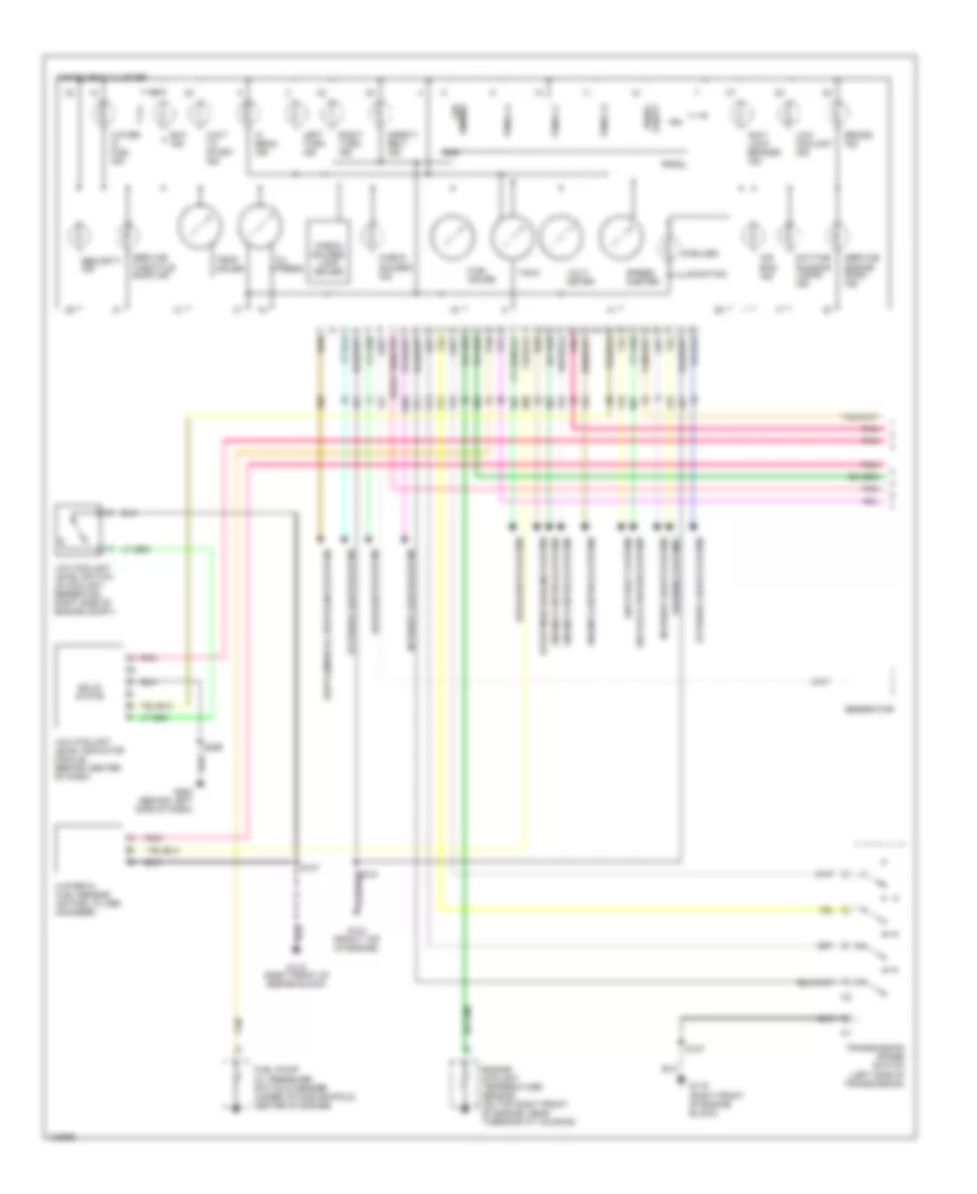
5.7L
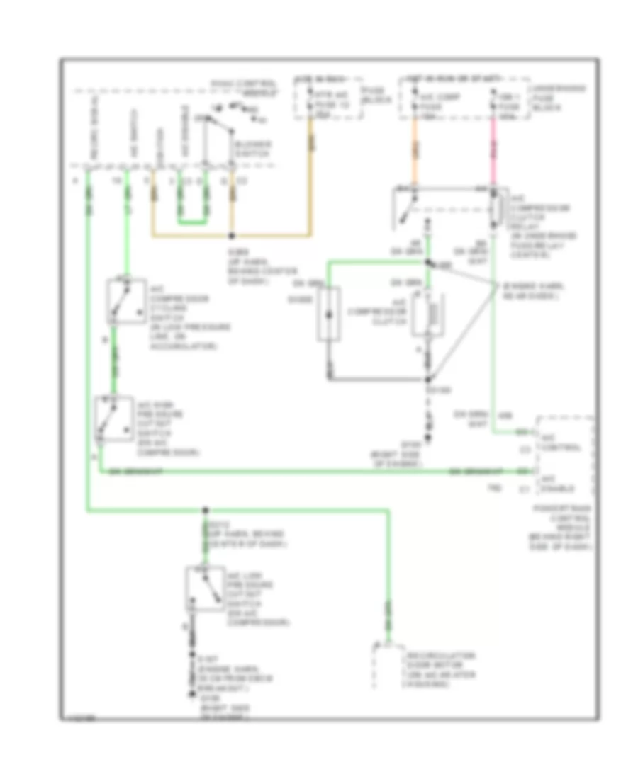
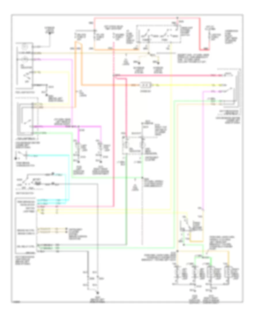
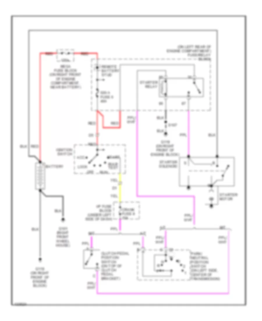
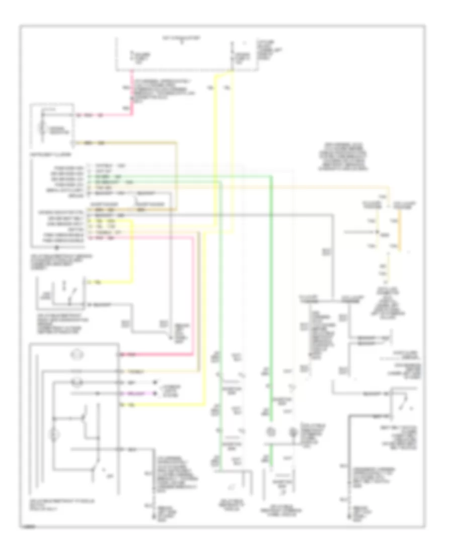
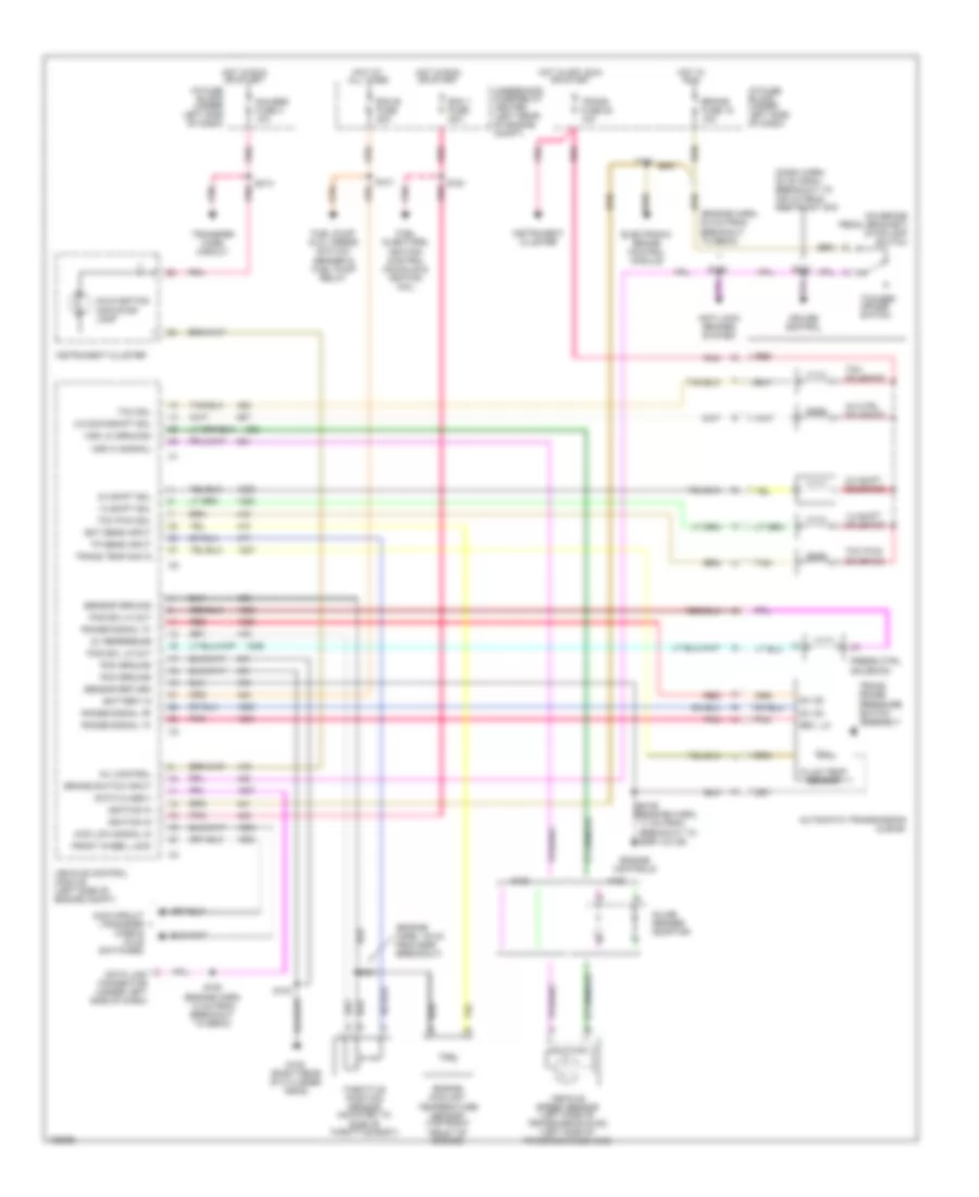
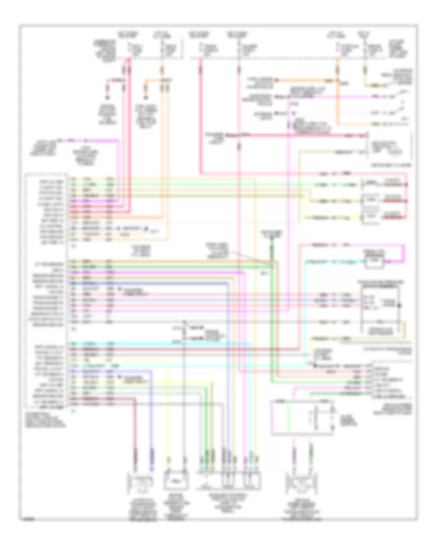
5.7L VIN R, Compressor Wiring Diagram for GMC CHD 2000 3500
 https://portal-diagnostov.com/license.html
Automotive Electricians Portal FZCO
Automotive Electricians Portal FZCO
https://portal-diagnostov.com/license.html
https://portal-diagnostov.com/license.html
Automotive Electricians Portal FZCO
Automotive Electricians Portal FZCO
List of elements for 5.7L VIN R, Compressor Wiring Diagram for GMC CHD 2000 3500:
- (engine harn, near diode)
- 22 cm from ebcm breakout)
- A/c comp fuse 10a
- A/c compressor clutch
- A/c compressor clutch relay (in underhood fuse block)
- A/c compressor cycling switch (in low pressure line, on accumulator)
- A/c control
- A/c disable
- A/c high pressure cutout switch (on a/c compressor)
- A/c low pressure cutout switch (on a/c compressor)
- A/c req
- A/c switch
- Blower switch
- Diode
- Fuse block
- G104 (top right side of cylinder head)
- G105 (right side of engine)
- Hot in run
- Hot in run or start
- Htr a/c fuse 12 25a
- Hvac control module
- Ign e fuse 10a
- Ignition
- Near egr valve breakout)
- Off
- Pnk
- S146 (eng harn, pnk
- S185
- S186
- S268 (i/p harn, behind center of dash)
- Sw sig
- Underhood fuse block
- Vehicle control module (left side of engine compt)
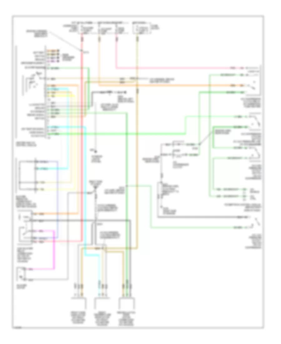
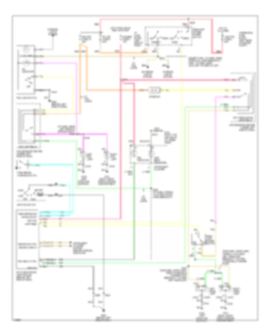
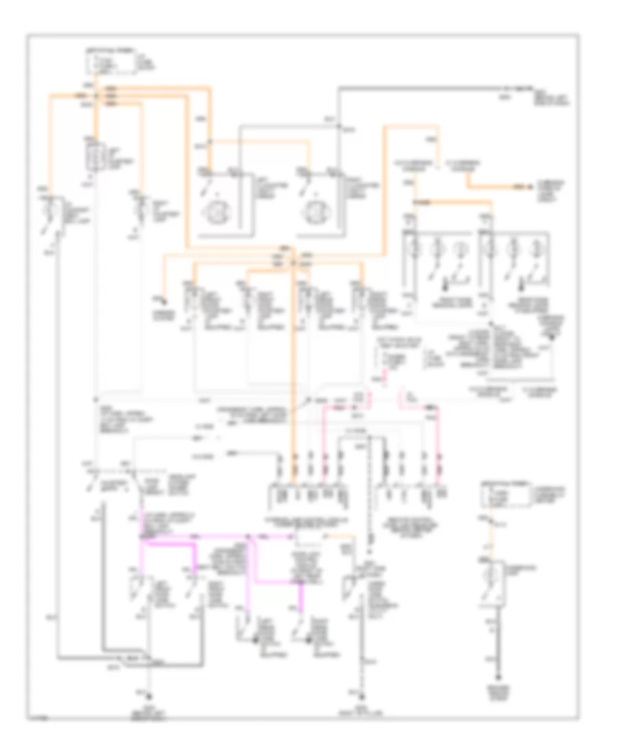
5.7L VIN R, Heater Wiring Diagram for GMC CHD 2000 3500
List of elements for 5.7L VIN R, Heater Wiring Diagram for GMC CHD 2000 3500:
- (behind left
- (hvac harn, 8 cm from recirc door breakout) s244
- (i/p harn, 24 cm from i/p cluster breakout)
- (right side of dash) g202
- Air temp dr sensor
- Battery
- Blower fuse 3 50a
- Blower motor (under right side of dash)
- Blower resistor (on blower motor housing)
- Blower switch
- Defogger element
- Front mode door motor (on front a/c-heater housing)
- Front temperature door motor (on front a/c-heater housing)
- Fuse block
- G200
- Ground
- High blower relay (on top of front a/c- heater blower housing)
- Hot at all times
- Hot in run
- Htr-a/c fuse 12 25a
- Hvac control module
- Ignition
- Illumination
- Interior lights system
- Mode signal
- Off
- Rear defogger system
- Recirc ctrl
- Recirculation door motor (on front a/c-heater housing)
- Red
- S243 (hvac harn, 4 cm from recirc door breakout)
- S268 (i/p harness, behind center of dash)
- S298
- Side of dash)
- Tan
- Underhood fuse/relay center
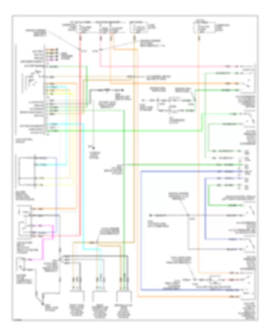
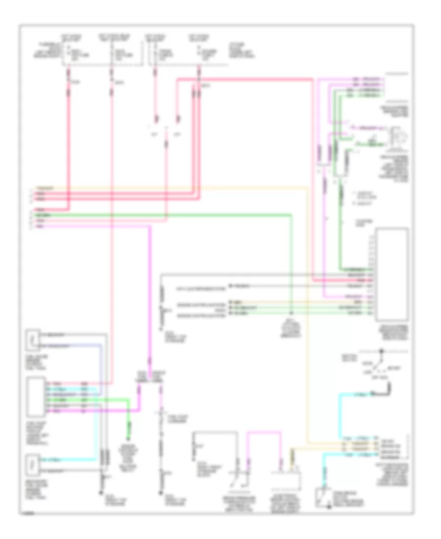
5.7L VIN R, Manual A/C Wiring Diagram for GMC CHD 2000 3500
List of elements for 5.7L VIN R, Manual A/C Wiring Diagram for GMC CHD 2000 3500:
- (engine harn, near diode)
- (engine harness, 22 cm from ebcm breakout, 7.4l)
- (engine harness, near ebcm breakout)
- (engine harness, near egr valve breakout)
- (exc 4.3 l)
- (fwd lamps harn, 5 cm from right headlamp breakout)
- (hvac harness, 4 cm from recirc door breakout)
- (i/p harn, 28 cm from cluster breakout)
- (i/p harness, behind center of dash)
- (right side
- A/c comp fuse 10a
- A/c compressor clutch
- A/c compressor clutch relay (in underhood fuse/relay center)
- A/c compressor cycling switch (in low pressure line, on accumulator)
- A/c ctrl
- A/c disable
- A/c high pressure cutout switch (on a/c compressor)
- A/c low pressure cutout switch (on a/c compressor)
- A/c req
- A/c switch
- Air temp dr sensor
- Aux fan fuse 30a
- Auxiliary cooling fan motor
- Auxiliary cooling fan relay (exc 4.3l) (in underhood fuse/relay center)
- Battery
- Blower fuse 3 50a
- Blower motor (under right side of dash)
- Blower resistor (on blower motor housing)
- Blower switch
- Defogger element
- Diode
- Front mode door motor (on front a/c-heater housing)
- Front temperature door motor (on front a/c-heater housing)
- Fuse block
- G104 (top right side of cylinder head)
- G105 (right side of engine)
- G112 (right front of engine compartment)
- G200 (behind left side of dash)
- G202
- Ground
- High blower relay (on top of front a/c-heater housing)
- Hot at all times
- Hot in run
- Hot in run or start
- Htr a/c fuse 12 25a
- Hvac control module
- Ign e fuse 10a
- Ignition
- Illumination
- Interior lights system
- Mode signal
- Of dash)
- Off
- Pnk
- Rear defogger system
- Recirc door signal
- Recirculation door motor (on front a/c-heater housing)
- Red
- Relay ctrl
- S103
- S110
- S128
- S146
- S185
- S186
- S212 (i/p harn, behind center of dash)
- S243
- S244 (hvac harn, 8 cm from recirc door breakout)
- S268
- S298
- Sw sig
- Tan
- Underhood fuse block
- Vehicle control module (left side of engine compt)
6.5L
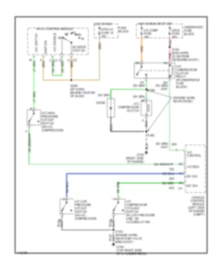
6.5L VIN F, Compressor Wiring Diagram for GMC CHD 2000 3500
List of elements for 6.5L VIN F, Compressor Wiring Diagram for GMC CHD 2000 3500:
- (engine harn, near diode)
- 30 cm from ebcm breakout)
- A/c comp fuse 10a
- A/c compressor clutch
- A/c compressor clutch relay (in underhood fuse/relay center)
- A/c compressor cycling switch (in low pressure line, on accumulator)
- A/c control
- A/c disable
- A/c enable
- A/c high pressure cutout switch (on a/c compressor)
- A/c low pressure cutout switch (on a/c compressor)
- A/c switch
- Blower switch
- Diode
- Fuse block
- G105 (right side of engine)
- Hot in run
- Hot in run or start
- Htr a/c fuse 12 25a
- Hvac control module
- Ign 1 fuse 10a
- Ignition
- Off
- Pnk
- Powertrain control module (behind right side of dash)
- Recirc signal
- Recirculation door motor (on a/c-heater housing)
- S185
- S186
- S268 (i/p harn, behind center of dash)
- Underhood fuse block
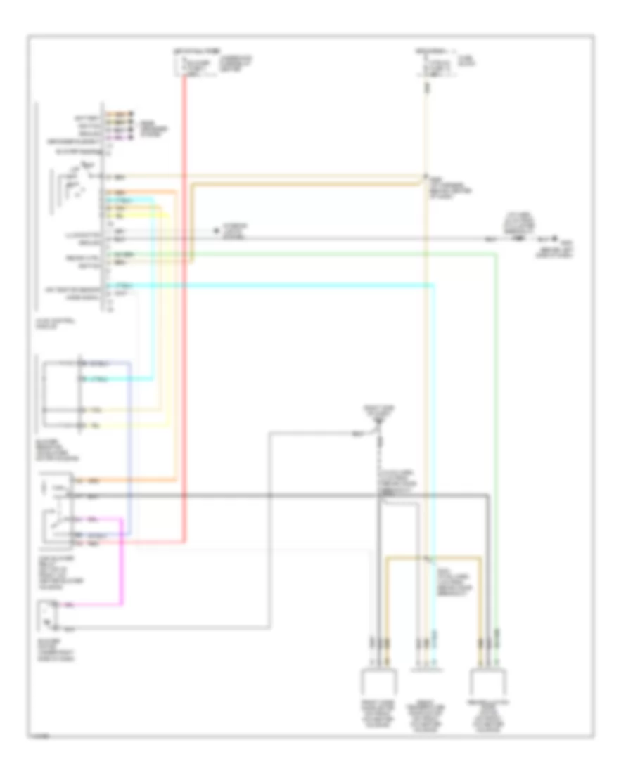
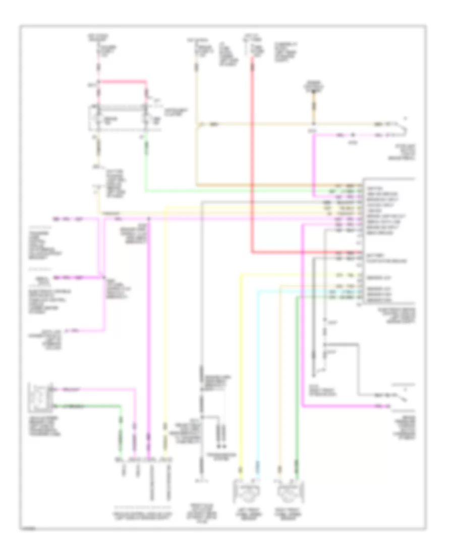
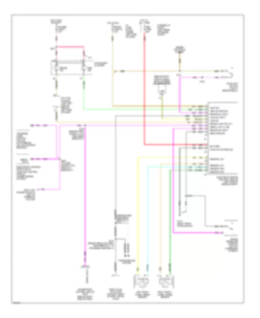
6.5L VIN F, Manual A/C Wiring Diagram for GMC CHD 2000 3500
List of elements for 6.5L VIN F, Manual A/C Wiring Diagram for GMC CHD 2000 3500:
- (behind right
- (engine harn,
- (engine harn, near diode)
- (engine harness, near ebcm breakout)
- (hvac harness, 4 cm from recirc door breakout)
- (hvac harness, 8 cm from recirc door breakout)
- (i/p harn, 24 cm from cluster breakout)
- (i/p harness, behind center of dash)
- (right side of dash) g202
- A/c comp fuse 10a
- A/c compressor clutch
- A/c compressor clutch relay (in underhood fuse center)
- A/c compressor cycling switch (in low pressure line, on accumulator)
- A/c ctrl
- A/c disable
- A/c enable
- A/c high pressure cutout switch (on a/c compressor)
- A/c low pressure cutout switch (on a/c compressor)
- A/c switch
- Air temp dr signal
- Battery
- Block
- Blower fuse 3 50a
- Blower motor
- Blower resistor (under right side of dash, on heater housing)
- Blower switch
- Defogger element
- Diode
- Front mode door motor (on front a/c-heater housing)
- Front temperature door motor (on front a/c-heater housing)
- Fuse
- Fuse block
- G105 (right side of engine)
- G200 (behind left side of dash)
- Ground
- Heater and a/c control module
- High blower relay (under dash on top of heater-a/c housing)
- Hot at all times
- Hot in run
- Hot in run or start
- Htr-a/c fuse 12 25a
- Ign e fuse 10a
- Ignition
- Illumination
- Interior lights system
- Mode signal
- Near diode)
- Off
- Pnk
- Powertrain control module
- Rear defogger system
- Recirc signal
- Recirculation door motor (under dash on heater- a/c housing)
- Red
- S107 (engine harn, 30 cm from breakout to ebcm)
- S110
- S185
- S186
- S212 (i/p harn, behind center of dash)
- S243
- S244
- S268
- S298
- Side of dash)
- Tan
- Underhood
7.4L
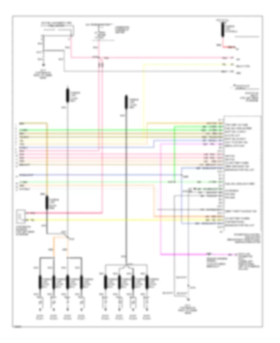
7.4L VIN J, Compressor Wiring Diagram for GMC CHD 2000 3500
List of elements for 7.4L VIN J, Compressor Wiring Diagram for GMC CHD 2000 3500:
- (engine harn, near diode)
- 22 cm from ebcm breakout)
- A/c comp fuse 10a
- A/c compressor clutch
- A/c compressor clutch relay (in underhood fuse block)
- A/c compressor cycling switch (in low pressure line, on accumulator)
- A/c control
- A/c disable
- A/c high pressure cutout switch (on a/c compressor)
- A/c low pressure cutout switch (on a/c compressor)
- A/c req
- A/c switch
- Blower switch
- Diode
- Fuse block
- G104 (top right side of cylinder head)
- G105 (right side of engine)
- Hot in run
- Hot in run or start
- Htr a/c fuse 12 25a
- Hvac control module
- Ign e fuse 10a
- Ignition
- Near egr valve breakout)
- Off
- Pnk
- S146 (eng harn, pnk
- S185
- S186
- S268 (i/p harn, behind center of dash)
- Sw sig
- Underhood fuse block
- Vehicle control module (left side of engine compt)
7.4L VIN J, Heater Wiring Diagram for GMC CHD 2000 3500
List of elements for 7.4L VIN J, Heater Wiring Diagram for GMC CHD 2000 3500:
- (behind left
- (hvac harn, 8 cm from recirc door breakout) s244
- (i/p harn, 24 cm from i/p cluster breakout)
- (right side of dash) g202
- Air temp dr sensor
- Battery
- Blower fuse 3 50a
- Blower motor (under right side of dash)
- Blower resistor (on blower motor housing)
- Blower switch
- Defogger element
- Front mode door motor (on front a/c-heater housing)
- Front temperature door motor (on front a/c-heater housing)
- Fuse block
- G200
- Ground
- High blower relay (on top of front a/c- heater blower housing)
- Hot at all times
- Hot in run
- Htr-a/c fuse 12 25a
- Hvac control module
- Ignition
- Illumination
- Interior lights system
- Mode signal
- Off
- Rear defogger system
- Recirc ctrl
- Recirculation door motor (on front a/c-heater housing)
- Red
- S243 (hvac harn, 4 cm from recirc door breakout)
- S268 (i/p harness, behind center of dash)
- S298
- Side of dash)
- Tan
- Underhood fuse/relay center
7.4L VIN J, Manual A/C Wiring Diagram for GMC CHD 2000 3500
List of elements for 7.4L VIN J, Manual A/C Wiring Diagram for GMC CHD 2000 3500:
- (engine harn, near diode)
- (engine harness, 22 cm from ebcm breakout, 7.4l)
- (engine harness, near ebcm breakout)
- (engine harness, near egr valve breakout)
- (exc 4.3 l)
- (fwd lamps harn, 5 cm from right headlamp breakout)
- (hvac harness, 4 cm from recirc door breakout)
- (i/p harn, 28 cm from cluster breakout)
- (i/p harness, behind center of dash)
- (right side
- A/c comp fuse 10a
- A/c compressor clutch
- A/c compressor clutch relay (in underhood fuse/relay center)
- A/c compressor cycling switch (in low pressure line, on accumulator)
- A/c ctrl
- A/c disable
- A/c high pressure cutout switch (on a/c compressor)
- A/c low pressure cutout switch (on a/c compressor)
- A/c req
- A/c switch
- Air temp dr sensor
- Aux fan fuse 30a
- Auxiliary cooling fan motor
- Auxiliary cooling fan relay (exc 4.3l) (in underhood fuse/relay center)
- Battery
- Blower fuse 3 50a
- Blower motor (under right side of dash)
- Blower resistor (on blower motor housing)
- Blower switch
- Defogger element
- Diode
- Front mode door motor (on front a/c-heater housing)
- Front temperature door motor (on front a/c-heater housing)
- Fuse block
- G104 (top right side of cylinder head)
- G105 (right side of engine)
- G112 (right front of engine compartment)
- G200 (behind left side of dash)
- G202
- Ground
- High blower relay (on top of front a/c-heater housing)
- Hot at all times
- Hot in run
- Hot in run or start
- Htr a/c fuse 12 25a
- Hvac control module
- Ign e fuse 10a
- Ignition
- Illumination
- Interior lights system
- Mode signal
- Of dash)
- Off
- Pnk
- Rear defogger system
- Recirc door signal
- Recirculation door motor (on front a/c-heater housing)
- Red
- Relay ctrl
- S103
- S110
- S128
- S146
- S185
- S186
- S212 (i/p harn, behind center of dash)
- S243
- S244 (hvac harn, 8 cm from recirc door breakout)
- S268
- S298
- Sw sig
- Tan
- Underhood fuse block
- Vehicle control module (left side of engine compt)
ANTI-LOCK BRAKES
5.7L
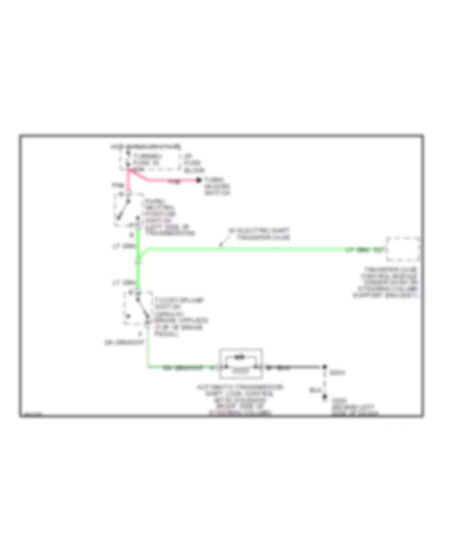
5.7L VIN R, Anti-lock Brake Wiring Diagrams for GMC CHD 2000 3500
List of elements for 5.7L VIN R, Anti-lock Brake Wiring Diagrams for GMC CHD 2000 3500:
- (engine harn, near ebcm breakout) s111
- (selectable 4wd harn, near breakout to transfer case relay)
- 4wd sw input
- Abs fuse 60a
- Abs ind
- Abs ind ground
- Battery
- Brake fuse 18 10a
- Brake ind
- Brake ind input
- Brake lamp ind out
- Brake pressure warning switch (underside of ebcm)
- Brake sw input
- Brake sw output
- Data link connector (dlc) (left of steering column)
- Daytime running lamp (drl) module (behind left side of dash)
- Ebcm ground
- Electronic brake control module (left side of engine compt)
- Electronic variable orifice (evo)/ passlock control module (under center of dash)
- Engine controls system
- Front axle actuator (on right rear of front drive axle)
- Fuse/relay block (left rear of engine compt)
- G119 (right front of eng block)
- Gauges fuse 4 10a
- Hot at all times
- Hot in run
- Hot in run or start
- I/p fuse block (under left side of dash)
- Ignition
- Instrument cluster
- Left front wheel speed sensor
- M/t
- Pnk
- Pump motor ground
- Red
- Right front wheel speed sensor
- S107
- S147
- S150 (engine harn, approx 13 cm from ebcm breakout)
- S151
- S152
- S213
- S280 (i/p harn, approx 5 cm from dlc breakout)
- S314
- Sensor high
- Sensor low
- Serial data
- Serial data line
- Stoplamp switch (top of brake pedal)
- Tan
- Transfer case control module (on steering column support bracket)
- Transmissions system
- Vehicle control module (vcm) (left side of engine compt)
- Vehicle speed sensor (vss) (left side of transmission/ transfer case)
- Vehicle speed sig
- Vss (+)
- Vss (-)
- Vss sig
6.5L
6.5L VIN F, Anti-lock Brake Wiring Diagrams for GMC CHD 2000 3500
List of elements for 6.5L VIN F, Anti-lock Brake Wiring Diagrams for GMC CHD 2000 3500:
- (behind right side of dash) vehicle speed sensor buffer
- 4wd sw input
- Abs fuse 60a
- Abs ind
- Abs ind ground
- Battery
- Brake fuse 18 10a
- Brake ind
- Brake ind input
- Brake lamp ind out
- Brake pressure warning switch (underside of ebcm)
- Brake sw input
- Data link connector (dlc) (left of steering column)
- Daytime running lamp (drl) module (behind left side of dash)
- Ebcm ground
- Electronic brake control module (left side of engine compt)
- Electronic variable orifice (evo)/ passlock control module (under center of dash)
- Engine controls system
- Front axle actuator (on right rear of front drive axle)
- Fuse/relay block (left rear of engine compt)
- G119 (right front of eng block)
- Gauges fuse 4 10a
- Hot at all times
- Hot in run
- Hot in run or start
- I/p fuse block (under left side of dash)
- Ignition
- Instrument cluster
- Left front wheel speed sensor
- M/t
- Pnk
- Powertrain control module (pcm) (behind right side of dash)
- Pump motor ground
- Red
- Right front wheel speed sensor
- S107
- S150 (engine harn, approx 13 cm from ebcm breakout)
- S151
- S152
- S213
- S280 (i/p harn, approx 5 cm from dlc breakout)
- S314 (selectable 4wd harn, near breakout to transfer case relay)
- Sensor high
- Sensor low
- Serial data
- Serial data line
- Stoplamp switch (top of brake pedal)
- Tan
- Transfer case control module (on steering column support bracket)
- Transmissions system
- Vss out
- Vss sig
7.4L
7.4L VIN J, Anti-lock Brake Wiring Diagrams for GMC CHD 2000 3500
List of elements for 7.4L VIN J, Anti-lock Brake Wiring Diagrams for GMC CHD 2000 3500:
- (engine harn, near ebcm breakout) s111
- (selectable 4wd harn, near breakout to transfer case relay)
- 4wd sw input
- Abs fuse 60a
- Abs ind
- Abs ind ground
- Battery
- Brake fuse 18 10a
- Brake ind
- Brake ind input
- Brake lamp ind out
- Brake pressure warning switch (underside of ebcm)
- Brake sw input
- Brake sw output
- Data link connector (dlc) (left of steering column)
- Daytime running lamp (drl) module (behind left side of dash)
- Ebcm ground
- Electronic brake control module (left side of engine compt)
- Electronic variable orifice (evo)/ passlock control module (under center of dash)
- Engine controls system
- Front axle actuator (on right rear of front drive axle)
- Fuse/relay block (left rear of engine compt)
- G119 (right front of eng block)
- Gauges fuse 4 10a
- Hot at all times
- Hot in run
- Hot in run or start
- I/p fuse block (under left side of dash)
- Ignition
- Instrument cluster
- Left front wheel speed sensor
- M/t
- Pnk
- Pump motor ground
- Red
- Right front wheel speed sensor
- S107
- S147
- S150 (engine harn, approx 13 cm from ebcm breakout)
- S151
- S152
- S213
- S280 (i/p harn, approx 5 cm from dlc breakout)
- S314
- Sensor high
- Sensor low
- Serial data
- Serial data line
- Stoplamp switch (top of brake pedal)
- Tan
- Transfer case control module (on steering column support bracket)
- Transmissions system
- Vehicle control module (vcm) (left side of engine compt)
- Vehicle speed sensor (vss) (left side of transmission/ transfer case)
- Vehicle speed sig
- Vss (+)
- Vss (-)
- Vss sig
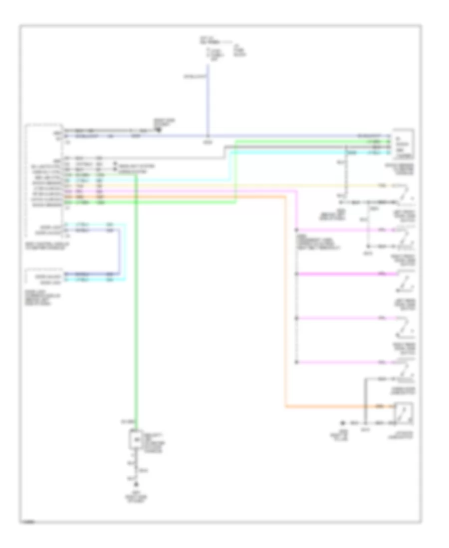
ANTI-THEFT
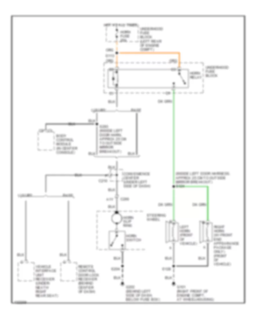
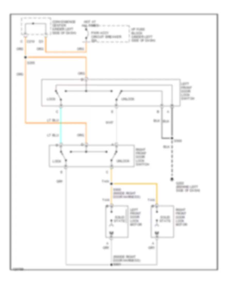
Forced Entry Wiring Diagram for GMC CHD 2000 3500
List of elements for Forced Entry Wiring Diagram for GMC CHD 2000 3500:
- (right side of dash) g201
- Body control module (in center console)
- C16
- Cargo door jamb switch
- Ctsy fuse 3 20a
- D11
- D12
- D13
- D14
- Door lock
- Door lock inversion module (behind left side of dash)
- Door unlock
- Ex lights ctrl
- G201 (right side of dash)
- G202 (behind left side of dash)
- G305 (right "b" pillar)
- Grd
- Hatch ajar sw
- Headlight system
- Horn rly ctrl
- Horns system
- Hot at all times
- I/p fuse block
- Left front door jamb switch
- Left rear door jamb switch
- Lf dr ajar sw
- Liftgate jamb switch
- Rf dr ajar sw
- Right front door jamb switch
- Right rear door jamb switch
- S204
- S218
- S262 (crossbody harn, approx 22 cm from seat belt breakout)
- S330
- S335
- S336
- S410
- Sec led ctrl
- Security led (in center of floor console)
- Shock
- Shock sensor
- Shock sensor (in center console)
- Tamper
- Tan
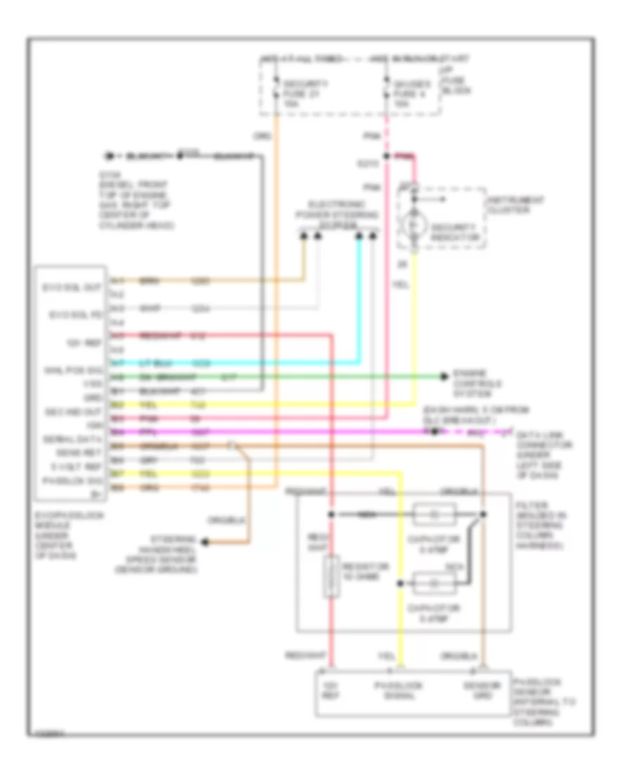
Pass-Key Wiring Diagram for GMC CHD 2000 3500
List of elements for Pass-Key Wiring Diagram for GMC CHD 2000 3500:
- (dash harn, 5 cm from dlc breakout) s280
- 12v ref
- 5 volt ref
- Capacitor 0.47mf
- Data link connector (under left side of dash)
- Electronic power steering system
- Engine controls system
- Evo sol fd
- Evo sol out
- Evo/passlock module (under center of dash)
- Filter (molded in steering column harness)
- G134 (diesel: front top of engine, gas: right top center of cylinder head)
- Gauges fuse 4 10a
- Grd
- Hot at all times
- Hot in run or start
- I/p fuse block
- Ign
- Instrument cluster
- Nca
- Passlck sig
- Passlock sensor (internal to steering column)
- Passlock signal
- Pnk
- Resistor 10 ohms
- S213
- S215
- Sec ind out
- Security fuse 21 10a
- Security indicator
- Sens ret
- Sensor grd
- Serial data
- Steering handwheel speed sensor (sensor ground)
- Vss
- Whl pos sig
COMPUTER DATA LINES
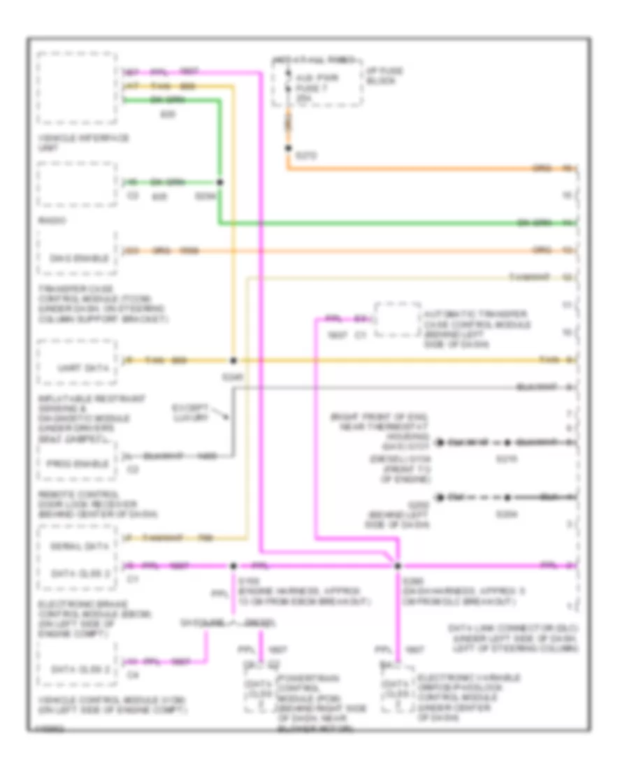
Computer Data Lines for GMC CHD 2000 3500
List of elements for Computer Data Lines for GMC CHD 2000 3500:
- (diesel) g134 (front to of engine)
- (right front of eng, near thermostat housing) (gas) g131
- 13 cm from ebcm breakout)
- Automatic transfer case control module (behind left side of dash)
- Aux pwr fuse 7 25a
- Data clss
- Data clss 2
- Data link connector (dlc) (under left side of dash, left of steering column)
- Diag enable
- Diesel
- Electronic brake control module (ebcm) (on left side of engine compt)
- Electronic variable orifice/passlock control module (under center of dash)
- Except luxury
- G202 (behind left side of dash)
- Gasoline
- Hot at all times
- I/p fuse block
- Inflatable restraint sensing & diagnostic module (under driver's seat carpet)
- Powertrain control module (pcm) (behind right side of dash, near blower motor)
- Prog enable
- Radio
- Remote control door lock receiver (behind center of dash)
- S204
- S215
- S245
- S272
- S280 (dash harness, approx 5 cm from dlc breakout)
- S294
- Serial data
- Tan
- Transfer case control module (tccm) (under dash, on steering column support bracket)
- Uart data
- Vehicle control module (vcm) (on left side of engine compt)
- Vehicle interface unit
COOLING FAN
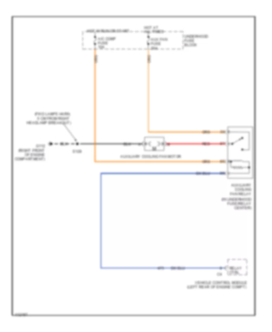
Cooling Fan Wiring Diagram for GMC CHD 2000 3500
List of elements for Cooling Fan Wiring Diagram for GMC CHD 2000 3500:
- (fwd lamps harn, 5 cm from right headlamp breakout)
- (in underhood fuse/relay center)
- A/c comp fuse 10a
- Aux fan fuse 30a
- Auxiliary cooling fan motor
- Auxiliary cooling fan relay
- G112 (right front of engine compartment)
- Hot at all times
- Hot in run or start
- Red
- Relay ctrl
- S128
- Underhood fuse block
- Vehicle control module (left rear of engine compt)
CRUISE CONTROL
5.7L
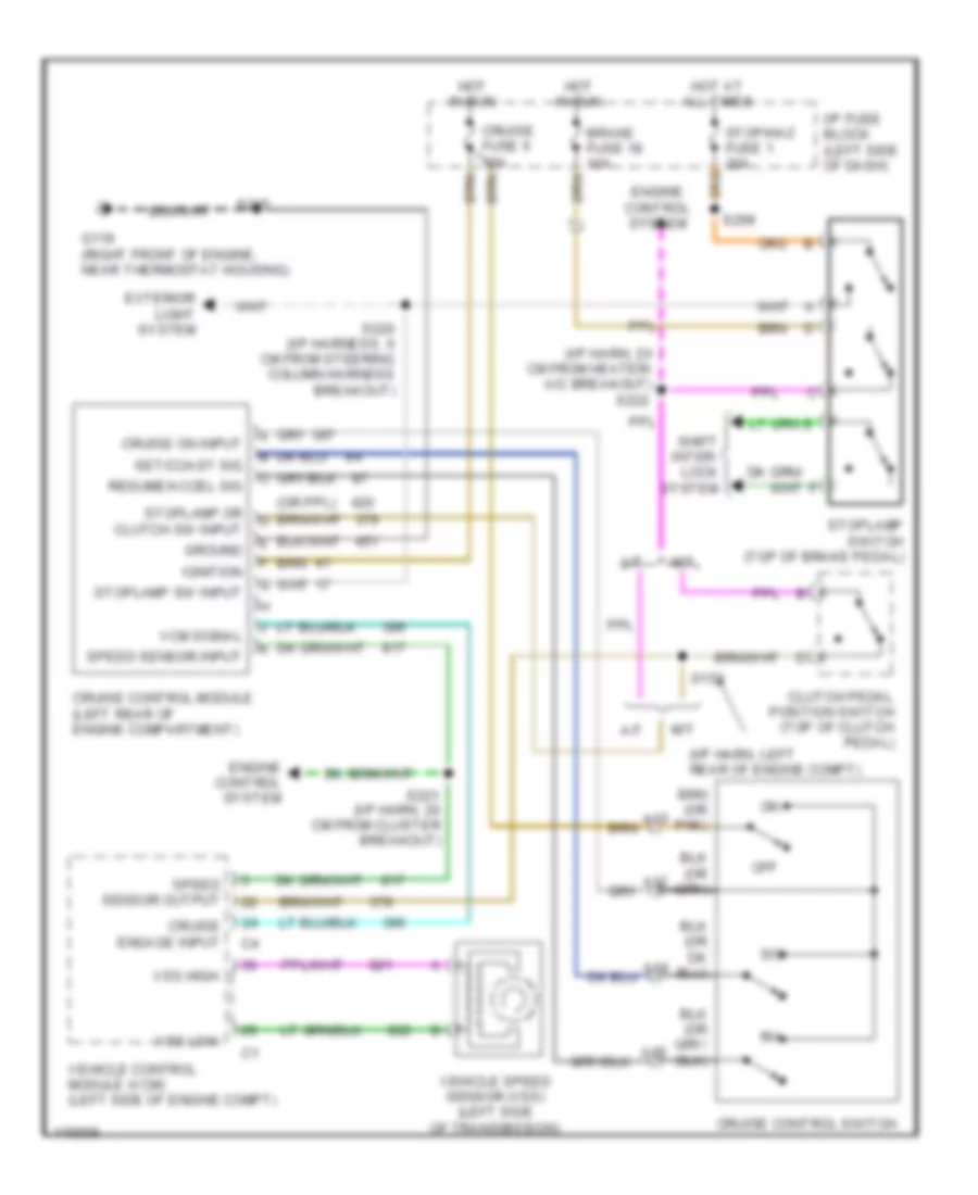
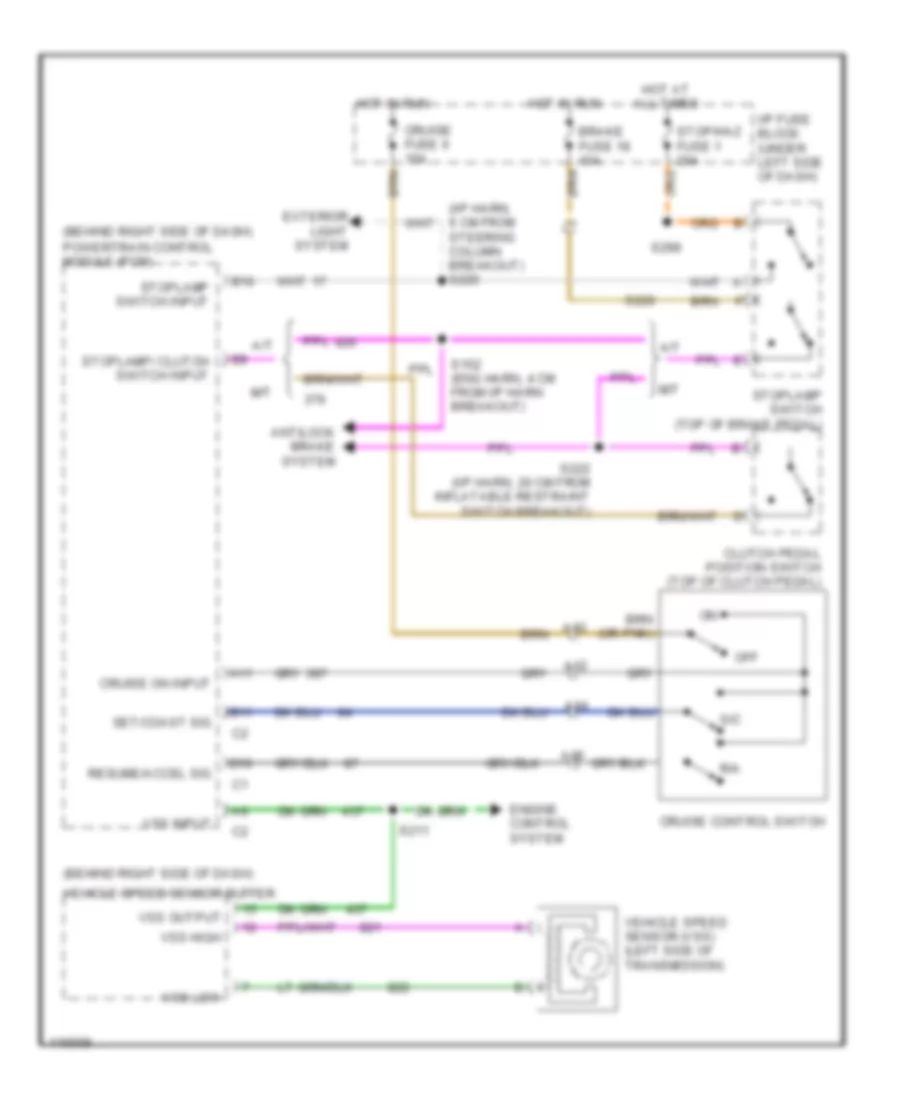
5.7L VIN R, Cruise Control Wiring Diagram for GMC CHD 2000 3500
List of elements for 5.7L VIN R, Cruise Control Wiring Diagram for GMC CHD 2000 3500:
- (i/p harn, 20 cm from heater/ a/c breakout) s222
- (i/p harn, left rear of engine compt)
- A/t
- A12
- A13
- A14
- A15
- Brake fuse 18 10a
- Clutch pedal position switch (top of clutch pedal)
- Cruise control module (left rear of engine compartment)
- Cruise control switch
- Cruise engage input
- Cruise fuse 6 10a
- Cruise on input
- Engine control system
- Exterior light system
- G119 (right front of engine, near thermostat housing)
- Ground
- Hot at all times
- Hot in run
- I/p fuse block (left side of dash)
- Ignition
- M/t
- Off
- R/a
- Resume/accel sig
- S/c
- S153
- S215
- S220 (i/p harness, 6 cm from steering column harness breakout)
- S221 (i/p harn, 20 cm from cluster breakout)
- S299
- Set/coast sig
- Shift inter- lock system
- Speed sensor input
- Speed sensor output
- Stop/haz fuse 1 20a
- Stoplamp or clutch sw input
- Stoplamp sw input
- Stoplamp switch (top of brake pedal)
- Vcm signal
- Vehicle control module (vcm) (left side of engine compt)
- Vehicle speed sensor (vss) (left side of transmission)
- Vss high
- Vss low
6.5L
6.5L VIN F, Cruise Control Wiring Diagram for GMC CHD 2000 3500
List of elements for 6.5L VIN F, Cruise Control Wiring Diagram for GMC CHD 2000 3500:
- (behind right side of dash)
- (behind right side of dash) powertrain control module (pcm)
- (i/p harn, 6 cm from steering column breakout) s220
- A/t
- A11
- A12
- A13
- A14
- A15
- Antilock brake system
- B10
- B11
- Brake fuse 18 10a
- Clutch pedal position switch (top of clutch pedal)
- Cruise control switch
- Cruise fuse 6 10a
- Cruise on input
- D10
- Engine control system
- Exterior light system
- Hot at all times
- Hot in run
- I/p fuse block (under left side of dash)
- M/t
- Off
- R/a
- Resume/accel sig
- S/c
- S152 (eng harn, 4 cm from i/p harn breakout)
- S211
- S220
- S222 (i/p harn, 20 cm from inflatable restraint switch breakout)
- S299
- Set/coast sig
- Stop/haz fuse 1 20a
- Stoplamp switch (top of brake pedal)
- Stoplamp switch input
- Stoplamp/ clutch switch input
- Vehicle speed sensor (vss) (left side of transmission)
- Vehicle speed sensor buffer
- Vss high
- Vss input
- Vss low
- Vss output
7.4L
7.4L VIN J, Cruise Control Wiring Diagram for GMC CHD 2000 3500
List of elements for 7.4L VIN J, Cruise Control Wiring Diagram for GMC CHD 2000 3500:
- (i/p harn, 20 cm from heater/ a/c breakout) s222
- (i/p harn, left rear of engine compt)
- A/t
- A12
- A13
- A14
- A15
- Brake fuse 18 10a
- Clutch pedal position switch (top of clutch pedal)
- Cruise control module (left rear of engine compartment)
- Cruise control switch
- Cruise engage input
- Cruise fuse 6 10a
- Cruise on input
- Engine control system
- Exterior light system
- G119 (right front of engine, near thermostat housing)
- Ground
- Hot at all times
- Hot in run
- I/p fuse block (left side of dash)
- Ignition
- M/t
- Off
- R/a
- Resume/accel sig
- S/c
- S153
- S215
- S220 (i/p harness, 6 cm from steering column harness breakout)
- S221 (i/p harn, 20 cm from cluster breakout)
- S299
- Set/coast sig
- Shift inter- lock system
- Speed sensor input
- Speed sensor output
- Stop/haz fuse 1 20a
- Stoplamp or clutch sw input
- Stoplamp sw input
- Stoplamp switch (top of brake pedal)
- Vcm signal
- Vehicle control module (vcm) (left side of engine compt)
- Vehicle speed sensor (vss) (left side of transmission)
- Vss high
- Vss low
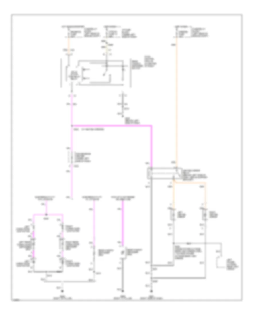
DEFOGGERS
Defogger Wiring Diagram for GMC CHD 2000 3500
List of elements for Defogger Wiring Diagram for GMC CHD 2000 3500:
- (w/ heated mirrors)
- C222
- Convenience center (under left side of dash)
- Fuse/relay block (left rear of engine compt)
- G201 (right side of dash)
- G202 (behind left side of dash)
- G305 (right "b" pillar)
- G905 (right "c" pillar)
- Heated mirror relay (behind left side of dash, above support bracket)
- Hot in run
- Hot in run or start
- Htr-a/c fuse 12 25a
- Hvac control module (in center of dash)
- I/p fuse block (under left side of dash)
- Left cargo door contactor
- Left heated mirror
- Left power outside rear view mirror
- Left rear cargo door defogger grid
- Mirrors fuse 10a
- Pick-up w/ extended or crew cab
- Rear window defogger grid
- Rear window defogger switch
- Right cargo door contactor
- Right heated mirror
- Right rear cargo door defogger grid
- Rr-defog fuse 30a
- S218
- S223
- S251
- S259
- S268
- S410
- S425
- S506 (inside power outside rear view mirror harn., 7 cm from power outside rear view mirror)
- Solid state time delay relay
- Suburban/utility w/ liftgate
- Suburban/utility w/o liftgate
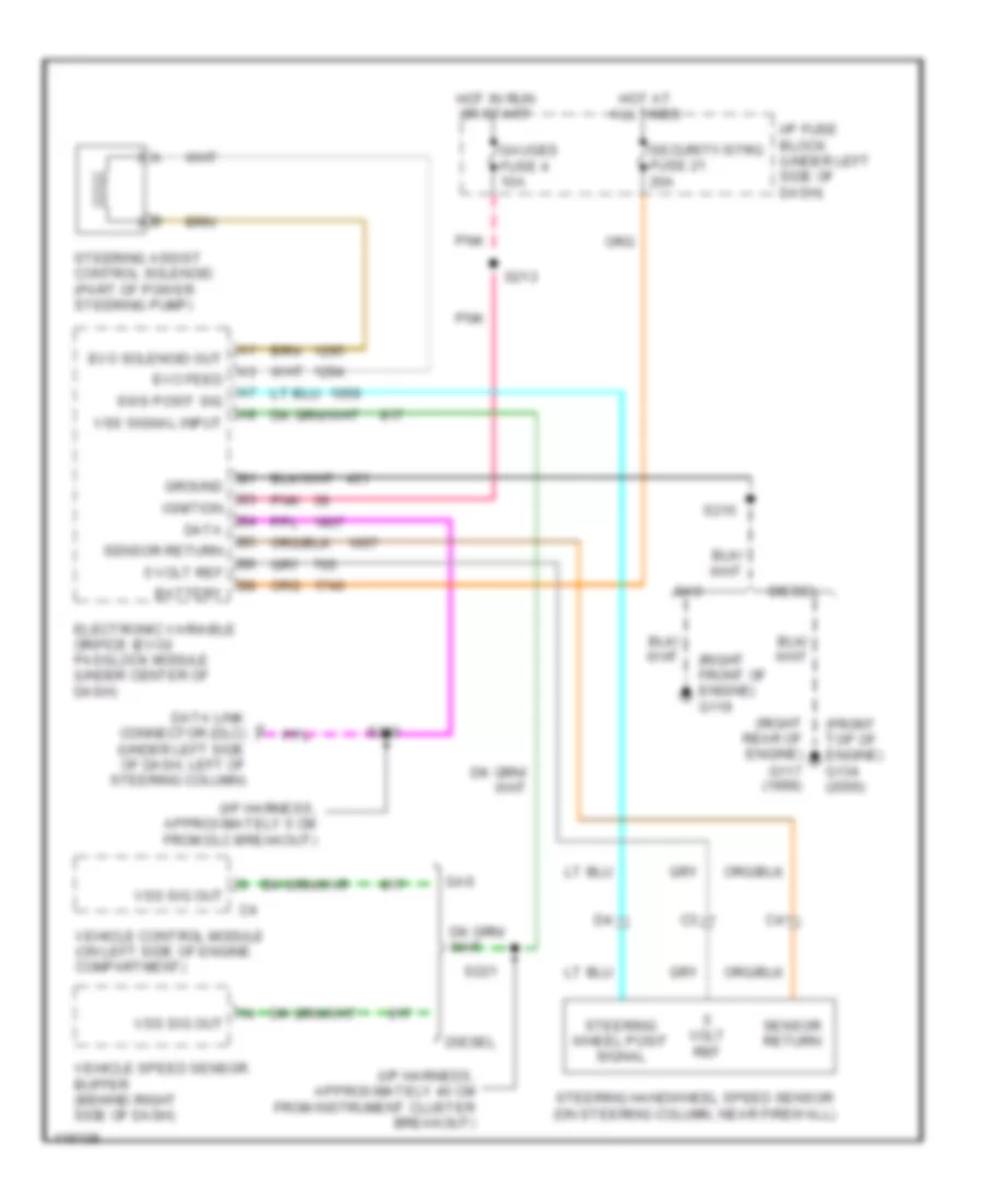
ELECTRONIC POWER STEERING
Electronic Power Steering Wiring Diagram for GMC CHD 2000 3500
List of elements for Electronic Power Steering Wiring Diagram for GMC CHD 2000 3500:
- (front top of engine) g134 (2000)
- (i/p harness, approximately 40 cm from instrument cluster breakout)
- (i/p harness, approximately 5 cm from dlc breakout)
- (right front of engine) g119
- (right rear of engine)
- 5 volt ref
- Battery
- Data
- Data link connector (dlc) (under left side of dash, left of steering column)
- Diesel
- Electronic variable orifice (evo)/ passlock module (under center of dash)
- Evo feed
- Evo solenoid out
- G117 (1999)
- Gas
- Gauges fuse 4 10a
- Ground
- Hot at all times
- Hot in run or start
- I/p fuse block (under left side of dash)
- Ignition
- Pnk
- S213
- S215
- S221
- S280
- Security/strg fuse 21 20a
- Sensor return
- Steering assist control solenoid (part of power steering pump)
- Steering handwheel speed sensor (on steering column, near firewall)
- Steering wheel posit signal
- Sws posit sig
- Vehicle control module (on left side of engine compartment)
- Vehicle speed sensor buffer (behind right side of dash)
- Volt ref
- Vss sig out
- Vss signal input
ENGINE PERFORMANCE
5.7L
5.7L VIN K, Engine Performance Wiring Diagrams (1 of 6) for GMC CHD 2000 3500
List of elements for 5.7L VIN K, Engine Performance Wiring Diagrams (1 of 6) for GMC CHD 2000 3500:
- (attached to right rear of throttle body) idle air control (iac) valve
- (bottom front of engine near, crank pulley) crankshaft position sensor
- (eng harn, 13 cm from fuse/relay center)
- (eng harn, 13 cm from starter solenoid breakout)
- (eng harn, 20 cm from fuse/relay center)
- (eng harn, 6.5 cm from cps breakout)
- (eng harn, 6.5 cm from starter solenoid breakout)
- (engine harn, 17 cm from under- hood fuse/relay center nreakout)
- (top right side of engine) evaporative emission canister purge solenoid valve
- 1-2 shift sol ctrl
- 2-3 shift sol ctrl
- 3-2 shift sol ctrl
- A/t w/ 4wd
- Air pump rel ctrl
- Cam posit sens sig
- Camshaft position sensor (inside distributor)
- Crank posit sens sig
- Ect sens sig
- Egr posit sig
- Fuel gauge lvl
- Fuel tank press sens
- G119 (right front of engine block)
- Heated oxygen sensor (bank 1 sensor 1) (in left exhaust pipe, in front of catalytic converter)
- Heated oxygen sensor (bank 2 sensor 1) (in right exhaust pipe, in front of catalytic converter)
- Heated oxygen sensor (below 8600 gvw: bank 1 sensor 2) (left exhaust pipe, behind catalytic converter (over 8600 gvw: bank 2 sensor 2) (right exhaust pipe, behind catalytic converter)
- Ho2s low
- Ho2s sig
- Iat sens sig
- Idle air ctrl (iac) a hi
- Idle air ctrl (iac) b lo
- Ign feed
- Inj 1 ctrl
- Inj 2 ctrl
- Inj 3 ctrl
- Inj 4 ctrl
- Inj 5 ctrl
- Inj 6 ctrl
- Inj 7 ctrl
- Inj 8 ctrl
- Inline gender adapter a
- Knock sens sig
- Knock sensor (ks) (right side of engine block, below exhaust manifold, forward of starter)
- Low ref
- Map sens input
- Mass air flow sens sig
- Nca
- Others
- Pnk
- Pnk c ignition feed
- S012
- S013
- S016
- S021
- S022
- S031
- S148
- S149
- S162
- Sens rtn
- Sens sig
- Sensor return
- Tan
- Tcc pwm sol ctrl
- Tcc sol ctrl
- Temp sens input
- Throttle posit sens
- Vehicle control module (vcm) (left side of engine compt)
- Vehicle speed sensor (left side of transmission, left side of transfer case w/ 4wd)
- Vent ctlr
- Vss sig
- Vss signal
5.7L VIN K, Engine Performance Wiring Diagrams (2 of 6) for GMC CHD 2000 3500
List of elements for 5.7L VIN K, Engine Performance Wiring Diagrams (2 of 6) for GMC CHD 2000 3500:
- (eng harn, 14 cm from thermostat ground stud breakout)
- (left front corner of eng compt) g100
- A 2-3 shift red
- A 3-2 shift solenoid
- A nca
- Air injection reaction pump motor (left front of eng compt)
- Air injection reaction pump relay (california) (underhood fuse/ relay center)
- Automatic transmission
- Automatic transmission fluid pressure (tfp) manual valve position switch
- Aux-b fuse 30a stud-b
- Ecm1 fuse 20a
- Eng1 k7
- Evaporative emissions (evap) canister vent valve (left side of engine compt)
- Exhaust gas recirculation (egr) valve (front of engine near thermostat housing)
- Fuel inj 1
- Fuel inj 2
- Fuel inj 3
- Fuel inj 4
- Fuel inj 5
- Fuel inj 6
- Fuel inj 7
- Fuel inj 8
- Fuse 20a l8
- Heated oxygen sensor (below 8600 gvw: bank 2 sensor 2) (right exhaust pipe, behind catalytic converter) (over 8600 gvw: bank 1 sensor 2) (left exhaust pipe behind catalytic converter)
- Hot at all times
- Hot in run & start
- Nca
- Pnk
- Pnk a
- Pressure control solenoid valve
- Red
- S018
- S104 pnk a
- S108
- S161
- S166 (eng harn, 18 cm from ebcm breakout)
- S167
- Solenoid
- Solenoid check valve
- Tan
- Tcc solenoid
- Torque converter red clutch pulse width modulation solenoid
- Trans fluid temperature sensor
- Under hood fuse/relay center
5.7L VIN K, Engine Performance Wiring Diagrams (3 of 6) for GMC CHD 2000 3500
List of elements for 5.7L VIN K, Engine Performance Wiring Diagrams (3 of 6) for GMC CHD 2000 3500:
- (af harness, 10 cm from hpl conn)
- (eng harn, 10 cm from thermostat ground stud breakout)
- (eng harn, 13 cm from cps breakout)
- (eng harn, 4 cm from fuse/relay center)
- (eng harn, near underhood lamp conn breakout)
- (produc- tion use)
- +5v ref
- 1x cam sens
- 4x crank in
- Actual gas
- Af ecu bat
- Af ecu gnd
- Af ecu ign
- Alternative fuel engine control unit (left side of engine compt)
- C001
- C002
- Class 2 data
- Cng fuse 20a
- Ect input
- Egr sens
- F pmp rly
- Fps +5v
- Fps sig
- Fps/fts gnd
- Fts sig
- Fuel lev out
- Fuel pressure sensor (end of cng fuel tank)
- Fuel temperature sensor (end of cng fuel tank)
- G119 (right front of engine)
- Gas flow out
- Gauge sel sw
- Hi pres lo
- Ho2s in
- Hot at all times
- Hot in run, bulb test and start
- Iat input
- Ign e fuse 10a
- Ind ctrl
- Low pres lo
- Maf input
- Map input
- Mil ctrl
- Mil out
- Ngo enable
- Pnk
- Red
- Relay ctrl
- S001
- S002
- S009
- S014
- S015
- S017
- S019
- S020
- S399
- Sensor gnd
- Serial data
- Tan
- Tp sensor
- Under hood fuse/relay center
- Vss input
5.7L VIN K, Engine Performance Wiring Diagrams (4 of 6) for GMC CHD 2000 3500
List of elements for 5.7L VIN K, Engine Performance Wiring Diagrams (4 of 6) for GMC CHD 2000 3500:
- (af harn, 32.5 cm from relay breakout)
- (af harn, near lpl breakout)
- Af d1 (af harn 10 cm from hpl conn)
- Af d2 (af harn 10 cm from lpl conn)
- Af fuel pump relay (left of engine compt)
- Fuel gauge relay (left of engine compt)
- Fuel gauge select switch
- G119 (right front of engine)
- Gas mass sensor (right front of engine)
- High pressure lock-off solenoid (end of cng fuel tank)
- Ignition relay (left of engine compt)
- Interior lights system
- Lock-off relay (left of engine compt)
- Low pressure lock-off solenoid (right middle of engine)
- Mixture control valve motor (right front of engine)
- Nca
- Pnk
- Red
- S003 (af harn, 22.5 cm from relay breakout)
- S004
- S005 (af harn, 13 cm from conn breakout)
- S009
- S010
- S011
- S398 (af harn, near breakout to hpl conn)
- S399
- Tan
5.7L VIN K, Engine Performance Wiring Diagrams (5 of 6) for GMC CHD 2000 3500
List of elements for 5.7L VIN K, Engine Performance Wiring Diagrams (5 of 6) for GMC CHD 2000 3500:
- (eng harn, approx 17 cm from breakout to egr valve) s106
- (eng harn, hd: 10 cm from egr valve breakout, ld: 27 cm from egr valve breakout)
- (engine harn, approx 16 cm from breakout to egr valve)
- (inside left frame rail, near rear crossmember)
- (right rear of cylinder head) g117
- (taillamp extension harn, 6 cm from the fuel pump harn breakout)
- Automatic transmission input shaft speed sensor (left side of transmission)
- C100
- C223
- Convenience center (under left side of dash)
- Engine coolant temperature sensor (top right front of engine, near thermostat housing)
- Fuel gauge input
- Fuel pump & sender (in fuel tank)
- Fuel tank pressure sensor (in fuel tank)
- G415
- Gauges fuse 4 10a
- Grd
- Hot in off, run or start
- Hot in run or start
- I/p fuse block
- Ign
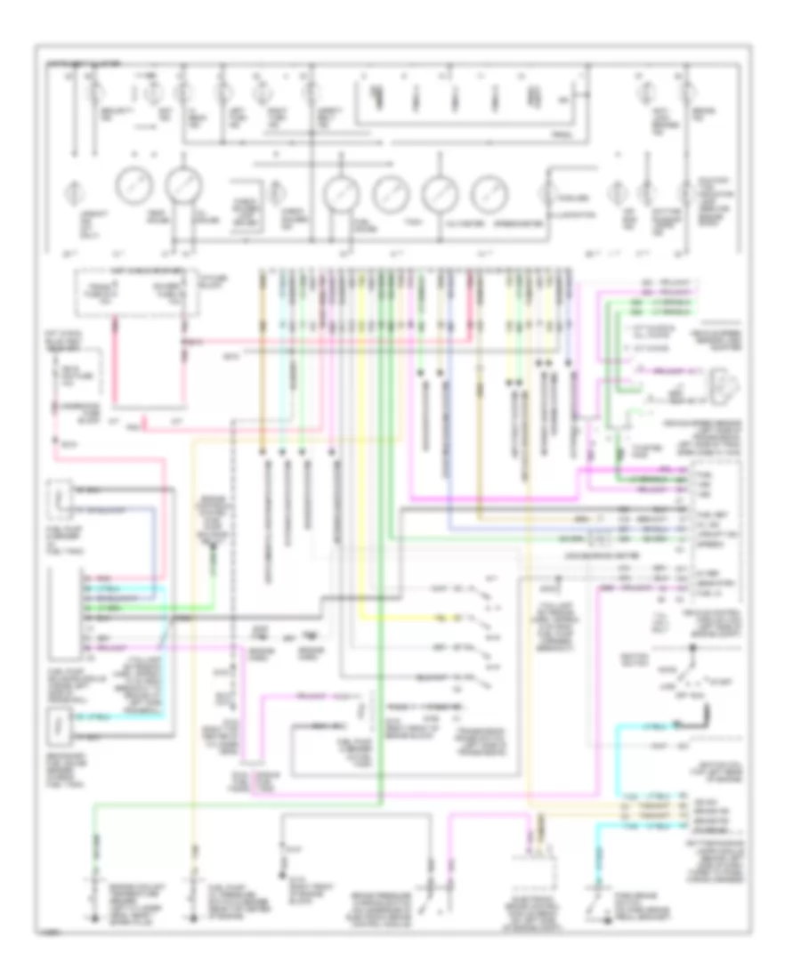
- Instrument cluster
- Intake air temperature sensor (in air intake duct)
- M/t only
- Manifold absolute pressure (map) sensor (top right of engine, near fuel injectors)
- Mass airflow sensor (in air intake duct)
- Pnk
- Red
- S103
- S131
- S213
- S231
- S232
- S430
- Service engine soon indicator
- Sig
- Speedometer input
- Tachometer input
- Tan
- Tan a
- Throttle position sensor (on throttle body assembly)
- Trans fuse 20 10a
- Upshift lamp
- W/o dual fuel tank
5.7L VIN K, Engine Performance Wiring Diagrams (6 of 6) for GMC CHD 2000 3500
List of elements for 5.7L VIN K, Engine Performance Wiring Diagrams (6 of 6) for GMC CHD 2000 3500:
- (engine harness, approx 13 cm from ebcm breakout) s150
- (engine harness, approx 7 cm from ebcm breakout)
- (i/p harn, 20 cm from inflatable restraint switch breakout)
- (i/p harn, harness, 13 cm from left engine grommet)
- (i/p harness, approx 40 cm from instrument cluster breakout)
- (or
- (right rear of cylinder head) g120
- 4wd input
- 5v ref voltage
- 87a
- A pnk
- A/c comp enable rel
- A/c request signal
- A/t
- Air conditioning system
- Air inlet vlv mtr ctlr
- Automatic 4wd
- Automatic transfer case shift controller
- Aux fan relay
- Brake sw input
- Brake switch input
- Check eng lp ctrl
- Clutch pedal position (cpp) switch (at top of clutch pedal bracket)
- Cooling fans system
- Cpp sw input
- Cruise control module (left rear of engine compt, on firewall)
- Cruise ctrl sig eng
- Data link connector (under left side of dash, left side of steering column)
- Distributor
- Egr vlv feed
- Egr vlv ground
- Electronic brake control module (ebcm) (on left side of engine compt)
- Electronic variable orifice/ passlock control module (center of dash)
- Est output sig
- Evap can purge vlv
- F11 ecmb fuse 20a
- Force motor feed
- Force motor return
- Four whl dr sig
- Four whl dr sig lo
- Fuel level input
- Fuel pump a prime connector (left rear of eng compt)
- Fuel pump relay
- Fuel pump rly ctrl
- G117 (right rear of cylinder head)
- G12
- Ground
- High voltage coil wire
- Hot at all times
- Hot in run
- I/p fuse block
- Ign coil out
- Ign input
- Ign timing sig.
- Ignition
- Ignition coil (top right rear of engine)
- Ignition control module (right side rear of engine)
- Ignition feed
- M/t
- M4 brake fuse 18 10a n3
- Manual or selectable 4wd
- Ngo input
- Pnk
- Pressure switch input
- Radio
- Red
- S101
- S103
- S111 (engine harness, approx 10 cm from ebcm breakout)
- S151
- S152
- S153
- S221
- Sensor ground
- Sensor return
- Serial data sig
- Shift ind lp out
- Speed sensor
- Speed sensor input
- Stoplamp switch (top of brake pedal)
- Stoplamp/ clutch switch input
- Switch signal
- Trans input speed rtn
- Trans input speed sig
- Transfer case control module (under dash, on steering column support bracket)
- Transfer case switch (left top of transfer case)
- Transmissions system
- Underhood fuse/ relay center
- Vcm sig
- Vehicle control module (vcm) (left side of engine compt)
- Vss input
- Vss sig out
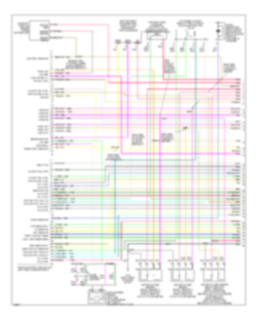
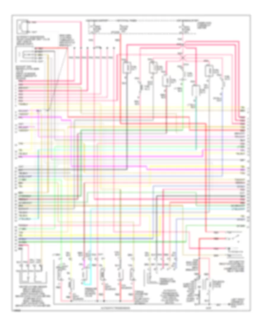
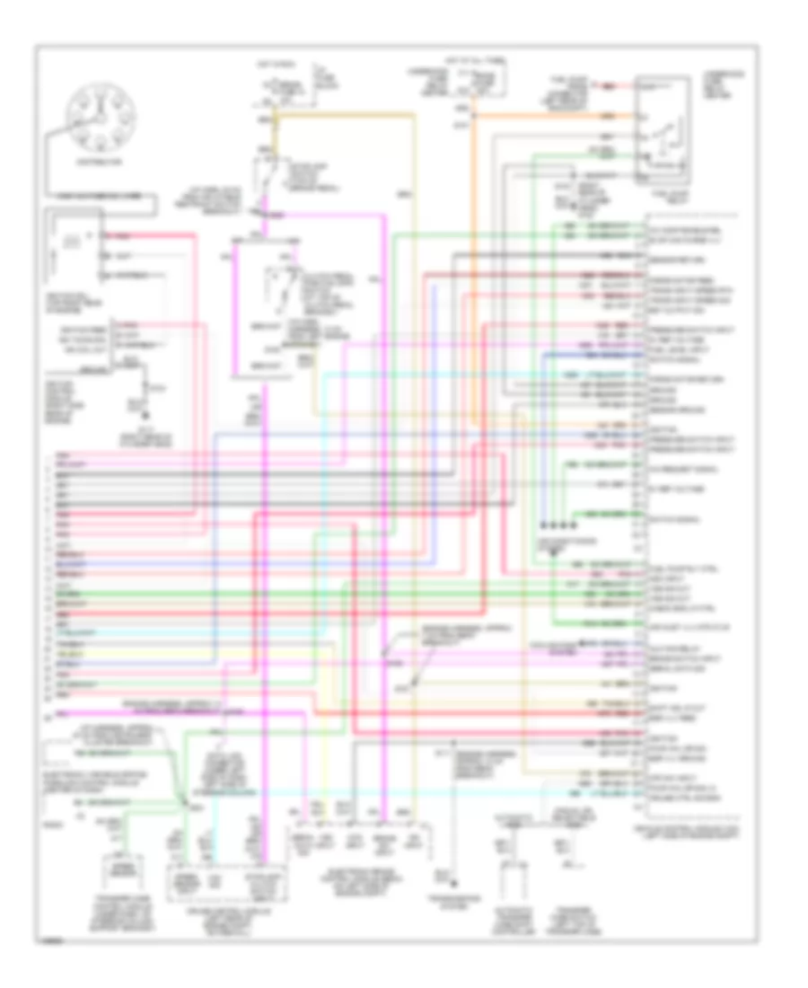
5.7L VIN R, Engine Performance Wiring Diagrams (1 of 4) for GMC CHD 2000 3500
List of elements for 5.7L VIN R, Engine Performance Wiring Diagrams (1 of 4) for GMC CHD 2000 3500:
- (attached to right rear of throttle body) idle air control (iac) valve
- (bottom front of engine near, crank pulley) crankshaft position sensor
- (top right side of engine) evaporative emission canister purge solenoid valve
- 1-2 shift sol ctrl
- 2-3 shift sol ctrl
- 3-2 shift sol ctrl
- A/t w/ 4wd
- Air pump rel ctrl
- Cam posit sens sig
- Camshaft position sensor (inside distributor)
- Crank posit sens sig
- Ect sens sig
- Egr posit sig
- Fuel gauge lvl
- Fuel tank press sens
- G119 (right front of engine block)
- Heated oxygen sensor (bank 1 sensor 1) (in left exhaust pipe, in front of catalytic converter)
- Heated oxygen sensor (bank 2 sensor 1) (in right exhaust pipe, in front of catalytic converter)
- Heated oxygen sensor (below 8600 gvw: bank 1 sensor 2) (left exhaust pipe, behind catalytic converter (over 8600 gvw: bank 2 sensor 2) (right exhaust pipe, behind catalytic converter)
- Ho2s low
- Ho2s sig
- Iat sens sig
- Idle air ctrl (iac) a hi
- Idle air ctrl (iac) b lo
- Ign feed
- Inj 1 ctrl
- Inj 2 ctrl
- Inj 3 ctrl
- Inj 4 ctrl
- Inj 5 ctrl
- Inj 6 ctrl
- Inj 7 ctrl
- Inj 8 ctrl
- Inline gender adapter a
- Knock sens sig
- Knock sensor (ks) (right side of engine block, below exhaust manifold, forward of starter)
- Low ref
- Map sens input
- Mass air flow sens sig
- Nca
- Others
- Pnk
- Pnk c ignition feed
- Pnk pnk
- S148
- S149
- S162
- Sens rtn
- Sens sig
- Sensor return
- Tan
- Tcc pwm sol ctrl
- Tcc sol ctrl
- Temp sens input
- Throttle posit sens
- Vehicle control module (vcm) (left side of engine compt)
- Vehicle speed sensor (left side of transmission, left side of transfer case w/ 4wd)
- Vent ctlr
- Vss sig
- Vss signal
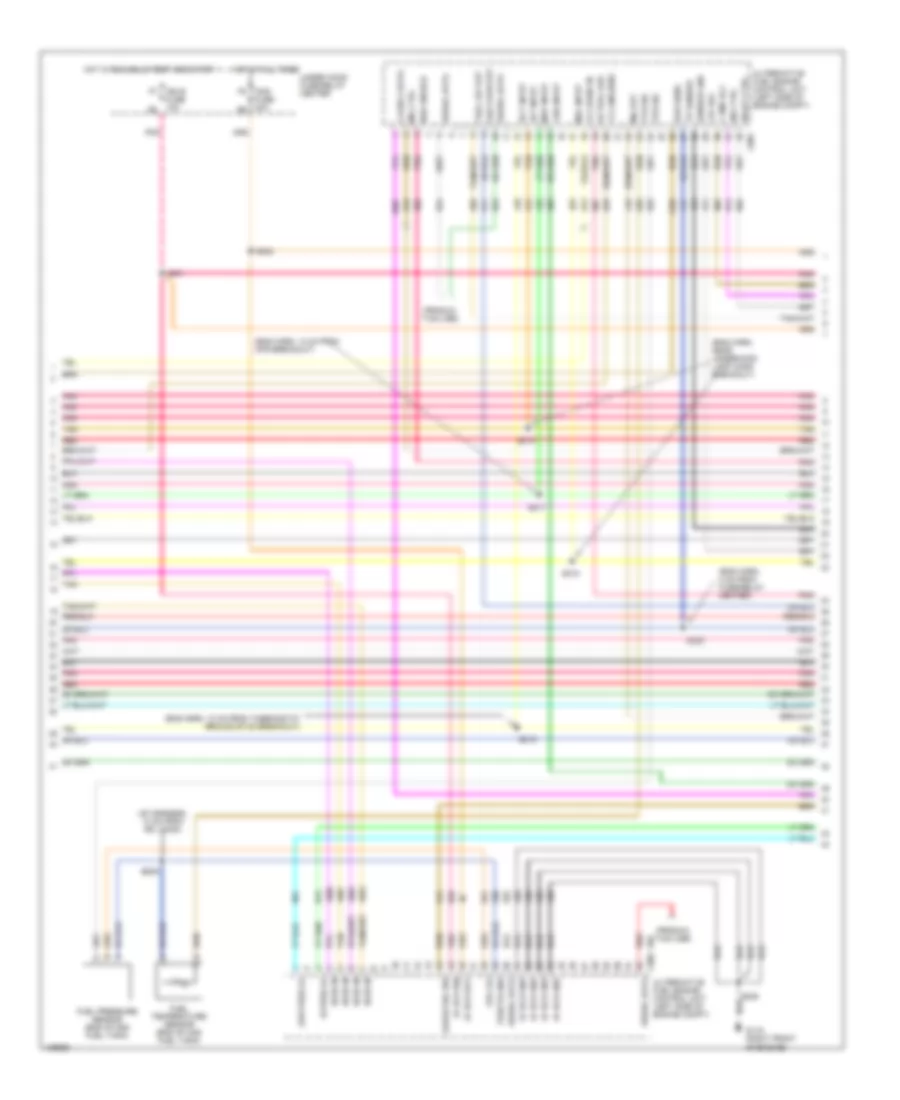
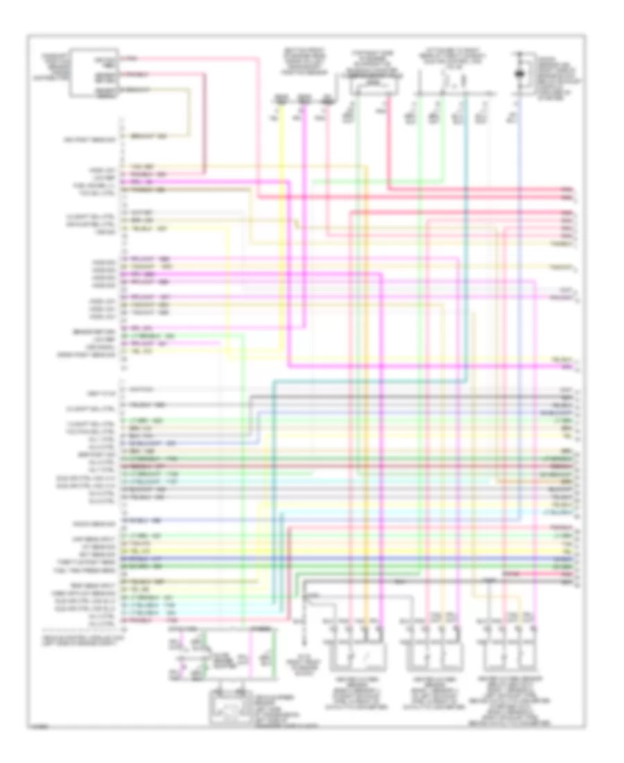
5.7L VIN R, Engine Performance Wiring Diagrams (2 of 4) for GMC CHD 2000 3500
List of elements for 5.7L VIN R, Engine Performance Wiring Diagrams (2 of 4) for GMC CHD 2000 3500:
- (left front corner of eng compt) g100
- A 2-3 shift red
- A 3-2 shift solenoid
- A nca
- Air injection reaction pump motor (left front of eng compt)
- Air injection reaction pump relay (california) (underhood fuse/ relay center)
- Automatic transmission
- Automatic transmission fluid pressure (tfp) manual valve position switch
- Aux-b fuse 30a stud-b
- Ecm1 fuse 20a
- Eng1 k7
- Evaporative emissions (evap) canister vent valve (left side of engine compt)
- Exhaust gas recirculation (egr) valve (front of engine near thermostat housing)
- Fuel inj 1
- Fuel inj 2
- Fuel inj 3
- Fuel inj 4
- Fuel inj 5
- Fuel inj 6
- Fuel inj 7
- Fuel inj 8
- Fuse 20a l8
- Heated oxygen sensor (below 8600 gvw: bank 2 sensor 2) (right exhaust pipe, behind catalytic converter) (over 8600 gvw: bank 1 sensor 2) (left exhaust pipe behind catalytic converter)
- Hot at all times
- Hot in run & start
- Nca
- Pnk
- Pnk pnk pnk tan red
- Pressure control solenoid valve
- Red
- S104
- S108
- S161
- S166 (eng harn, 18 cm from ebcm breakout)
- S167
- Solenoid
- Solenoid check valve
- Tan
- Tcc solenoid
- Torque converter red clutch pulse width modulation solenoid
- Trans fluid temperature sensor
- Under hood fuse/relay center
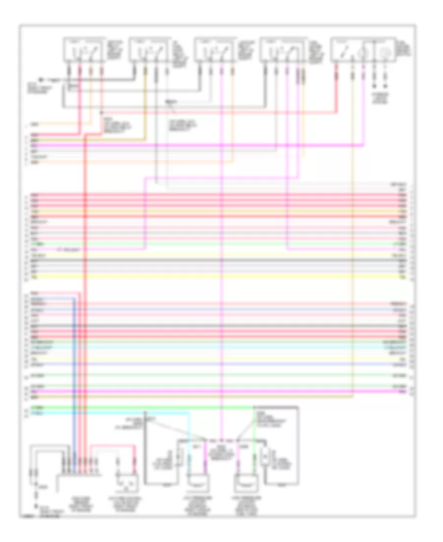
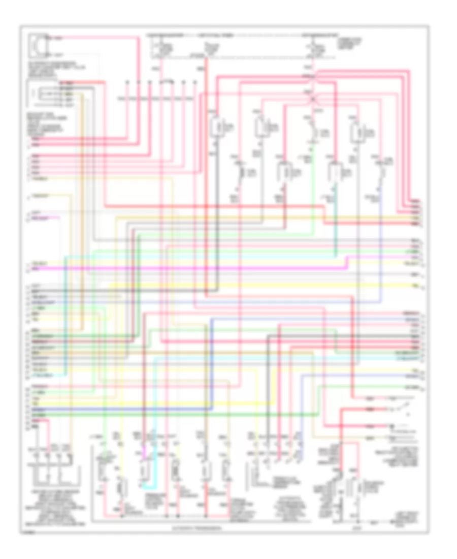
5.7L VIN R, Engine Performance Wiring Diagrams (3 of 4) for GMC CHD 2000 3500
List of elements for 5.7L VIN R, Engine Performance Wiring Diagrams (3 of 4) for GMC CHD 2000 3500:
- (eng harn, approx 17 cm from breakout to egr valve) s106
- (eng harn, hd: 10 cm from egr valve breakout, ld: 27 cm from egr valve breakout)
- (engine harn, approx 16 cm from breakout to egr valve)
- (inside left frame rail, near rear crossmember)
- (right rear of cylinder head) g117
- (taillamp extension harn, 6 cm from the fuel pump harn breakout)
- Automatic transmission input shaft speed sensor (left side of transmission)
- C100
- C223
- Convenience center (under left side of dash)
- Engine coolant temperature sensor (top right front of engine, near thermostat housing)
- Fuel gauge input
- Fuel pump & sender (in fuel tank)
- Fuel tank pressure sensor (in fuel tank)
- G415
- Gauges fuse 4 10a
- Grd
- Hot in off, run or start
- Hot in run or start
- I/p fuse block
- Ign
- Input
- Instrument cluster
- Intake air temperature sensor (in air intake duct)
- M/t only
- Manifold absolute pressure (map) sensor (top right of engine, near fuel injectors)
- Mass airflow sensor (in air intake duct)
- Pnk
- Pnk pnk tan red
- S103
- S213
- S231
- S232
- S430
- Service engine soon indicator
- Sig
- Speedometer input
- Tachometer
- Tan a
- Throttle position sensor (on throttle body assembly)
- Trans fuse 20 10a
- Upshift lamp
- W/o dual fuel tank
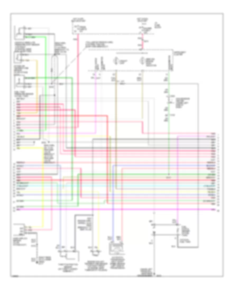
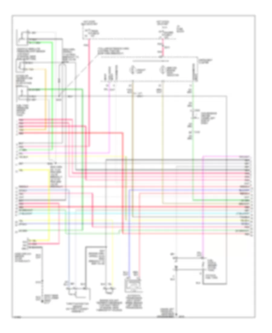
5.7L VIN R, Engine Performance Wiring Diagrams (4 of 4) for GMC CHD 2000 3500
List of elements for 5.7L VIN R, Engine Performance Wiring Diagrams (4 of 4) for GMC CHD 2000 3500:
- (engine harness, approx 13 cm from s150
- (engine harness, approx 7 cm from ebcm breakout)
- (i/p harn, 20 cm from inflatable restraint switch breakout)
- (i/p harn, harness, 13 cm from left engine grommet)
- (i/p harness, approx 40 cm from instrument cluster breakout)
- (or
- (right rear of cylinder head) g120
- 4wd input
- 5v ref voltage
- 87a
- A pnk
- A/c comp enable rel
- A/c request signal
- A/t
- Air conditioning system
- Air inlet vlv mtr ctlr
- Automatic 4wd
- Automatic transfer case shift controller
- Aux fan relay
- Brake sw input
- Brake switch input
- Check eng lp ctrl
- Clutch pedal position (cpp) switch (at top of clutch pedal bracket)
- Cooling fans system
- Cpp sw input
- Cruise control module (left rear of engine compt, on firewall)
- Cruise ctrl sig eng
- Data link connector (under left side of dash, left side of steering column)
- Distributor
- Ebcm breakout)
- Egr vlv feed
- Egr vlv ground
- Electronic brake control module (ebcm) (on left side of engine compt)
- Electronic variable orifice/ passlock control module (center of dash)
- Est output sig
- Evap can purge vlv
- F11 ecmb fuse 20a
- Force motor feed
- Force motor return
- Four whl dr sig
- Four whl dr sig lo
- Fuel level input
- Fuel pump a prime connector (left rear of eng compt)
- Fuel pump relay
- Fuel pump rly ctrl
- G117 (right rear of cylinder head)
- G12
- Ground
- High voltage coil wire
- Hot at all times
- Hot in run
- I/p fuse block
- Ign coil out
- Ign input
- Ign timing sig.
- Ignition
- Ignition coil (top right rear of engine)
- Ignition control module (right side rear of engine)
- Ignition feed
- M/t
- M4 brake fuse 18 10a n3
- Manual or selectable 4wd
- Pnk
- Pressure switch input
- Radio
- Red
- S101
- S103
- S111 (engine harness, approx 10 cm from ebcm breakout)
- S151
- S152
- S153
- S221
- Sensor ground
- Sensor return
- Serial data sig
- Shift ind lp out
- Speed sensor
- Speed sensor input
- Stoplamp switch (top of brake pedal)
- Stoplamp/ clutch switch input
- Switch signal
- Trans input speed rtn
- Trans input speed sig
- Transfer case control module (under dash, on steering column support bracket)
- Transfer case switch (left top of transfer case)
- Transmissions system
- Underhood fuse/ relay center
- Vcm sig
- Vehicle control module (vcm) (left side of engine compt)
- Vss input
- Vss sig out
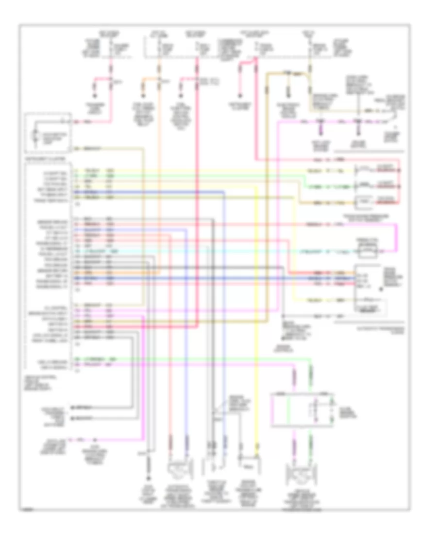
6.5L
6.5L VIN F, Engine Performance Wiring Diagrams (1 of 4) for GMC CHD 2000 3500
List of elements for 6.5L VIN F, Engine Performance Wiring Diagrams (1 of 4) for GMC CHD 2000 3500:
- (bottom front of engine, near crank pulley) crankshaft position (ckp) sensor
- (engine harn, 31 cm from taillamp harn breakout)
- (i/p harn, approx 16 cm into i/p cluster breakout)
- (top center of engine) boost pressure sensor
- (top of engine, near
- (top rear of right cylinder head) g117
- (top right front of engine, near thermostat housing) engine coolant temperature (ect) sensor
- 4wd signal
- 5 volt ref
- 5 vref
- 5v ref volt
- A 1-2 red shift sol
- A 2-3 red shift sol
- A torque red converter clutch pulse wdth mod sol
- A/c request sig
- A/c system
- A/t fluid pressure (tfp) manual valve position switch
- A/t w/ 4wd
- A10
- A11 3 mode cruise a12
- Anti-lock brakes system
- App 1 sig
- App 2 sig
- App 3 sig
- Automatic transmission
- Automatic transmission input shaft speed (a/t iss) sensor (left side of transmission)
- B10
- B11
- B12
- Brake sw in
- Brake switch input
- C10
- C11
- C12
- C13
- C14
- C15
- C16
- Cam posit sens sig rtn
- Camshaft posit sens
- Closure gnd
- Cruise control system
- Cruise ctrl sw engage
- Cruise eng sw retard
- D10
- D11
- D12
- D13
- D14
- D15
- D16
- Ect temp sens in
- Engine crank sens input
- Force mtr hi
- Force mtr low
- Fuel pump input
- Fuel pump rly ctrl
- Fuel sol closure (5v sig)
- Fuel temp sens (5v sig)
- Glow plug "wait" lp out
- Glow plug relay
- Ground
- Ign
- Inline gender adapter
- Intake air temperature (iat) sensor
- Intake man air temp sens
- Intake manifold
- Map sens input
- Nca
- Opening)
- Others
- Pnk
- Powertrain control module (pcm) (behind right side of dash, near blower motor)
- Pressure control solenoid valve
- Radio, evo/ passlock control module, transfer case control module
- Range mode sel a
- Range mode sel b
- Range mode sel c
- Red
- S140
- S170
- S199
- S211
- S215
- Sensor gnd
- Tan
- Timing stepper mtr (high)
- Timing stepper mtr (low)
- Transmission speed input
- Transmission temp input
- Transmission temperature sensor
- Transmissions system
- Vehicle speed input
- Vehicle speed sensor (left side of transmission)
- Vehicle speed sensor buffer (behind right side of dash)
- Vss hi
- Vss lo
- Vss output
- Vss rtn
- Vss sig
6.5L VIN F, Engine Performance Wiring Diagrams (2 of 4) for GMC CHD 2000 3500
List of elements for 6.5L VIN F, Engine Performance Wiring Diagrams (2 of 4) for GMC CHD 2000 3500:
- (a/t: eng harn, approx 4 cm from i/p harness breakout, m/t: i/p harn, 20 cm from inflatable restraint i/p module switch breakout)
- (on inj pump)
- 5 volt ref
- Accelerator pedal position (app) module (part of accelerator pedal)
- Clutch pedal position (cpp) switch (m/t only) (top of clutch pedal bracket)
- Cmp sig
- D2 trans fuse 20 20a e1
- D8 stop/haz fuse 1 20a c7
- Ecm-1 h7
- Electronic brake control module (on left side of engine compt)
- Engine shutoff solenoid (top of fuel injection pump)
- Fuel solenoid (rear of fuel injection pump)
- Fuel solenoid driver (left side of fuel injection pump)
- Fuse 20a
- High res sig
- Hot at all times
- Hot in run
- Hot in run or start
- I/p fuse block
- Injection timing stepper motor (top right front of engine)
- M4 brake fuse 18 10a n3
- Nca
- Optical fuel temperature sensor (on top of fuel injection pump)
- Pnk
- Pnk pnk
- Power distribution system
- Red
- S166
- S190
- S198
- S220 (i/p harness, approx 6 cm from steering column breakout)
- S222 (m/t) s152 (a/t)
- S299
- Sens grd
- Stop- lamp switch (on top of brake pedal)
- Tan d
- Underhood fuse/relay center
6.5L VIN F, Engine Performance Wiring Diagrams (3 of 4) for GMC CHD 2000 3500
List of elements for 6.5L VIN F, Engine Performance Wiring Diagrams (3 of 4) for GMC CHD 2000 3500:
- (inside left frame rail, below driver's door)
- (m/t: engine harness, approx 37 cm from breakout to ebcm, a/t: engine harness, approx 31 cm from taillamp harn breakout) s100
- (taillamp ext harn, 10 cm from fuel pump balance mod breakout)
- (top rear of right cylinder head)
- (top rear of right cylinder head) g117
- Auxiliary tank fuel level sensor
- Ecm-b fuse 20a
- F11
- Fuel balance pump
- Fuel gauge
- Fuel lift pump
- Fuel pump balance module (inside left side frame rail)
- Fuel pump balance relay (on fuel pump balance module)
- Fuel pump prime connector (left side of eng compt)
- Fuel pump relay (in under fuse- relay center)
- Fuel pump/oil pressure switch
- G117
- G12
- G415 (inside left frame rail, near rear crossmember)
- Gauges fuse 4 10a
- Hot at all times
- Hot in run or start
- I/p fuse block
- Ign--e fuse 10a
- Instrument cluster
- Instrument cluster system
- Nca
- Pnk
- Primary tank fuel level sensor
- Red
- S101
- S103
- S147
- S213
- S315
- S317
- S318
- S319
- Service engine soon indicator
- Service throttle soon indicator
- Tan
- Underhood fuse/relay center
- Vehicle speed input
- W/ dual tanks
- W/o dual tank
- Wait to start "glow plugs" indicator
- Water in fuel indicator
- Water in-fuel sensor (on fuel filter/ manager)
6.5L VIN F, Engine Performance Wiring Diagrams (4 of 4) for GMC CHD 2000 3500
List of elements for 6.5L VIN F, Engine Performance Wiring Diagrams (4 of 4) for GMC CHD 2000 3500:
- "serv eng soon" ind
- "serv throttle soon" ind
- (engine harness, approx 13 cm into ebcm breakout)
- (on fuel manager/filter) fuel heater
- 12v battery (fused)
- 12v battery fused
- 3/2 ctrl out
- A/c enable
- A/c system
- C10
- C11
- C12
- C13
- C14
- C15
- C16
- D10
- D11
- D12
- D13
- D14
- D15
- D16
- Data link connector (dlc) (under left side of dash, left of steering column)
- Eng-i k7
- Engine shutoff sol out
- Fuel sol module (5 vref)
- Fuel sol module feed
- Fuse 20a
- Fusible link
- G117 (top rear of right cylinder head)
- Glow plug 1
- Glow plug 2
- Glow plug 3
- Glow plug 4
- Glow plug 5
- Glow plug 6
- Glow plug 7
- Glow plug 8
- Glow plug output
- Glow plug relay (top left rear of engine)
- Grd
- Hot at all times
- Hot in run or start
- Ign
- Ignition
- Nca
- Pcm gnd
- Pnk
- Powertrain control module (pcm) (behind right side of dash, near blower motor)
- Red
- Relay ctrl
- S103
- S108
- S137
- S138
- S147
- S150
- S191
- S269
- Serial data sig
- Shift sol a input
- Shift sol b input
- Tan
- Tps 2 ref voltage
- Underhood fuse/relay center
- Wait to start ind
- Wastegate sol
- Wastegate solenoid (top left rear of engine)
7.4L
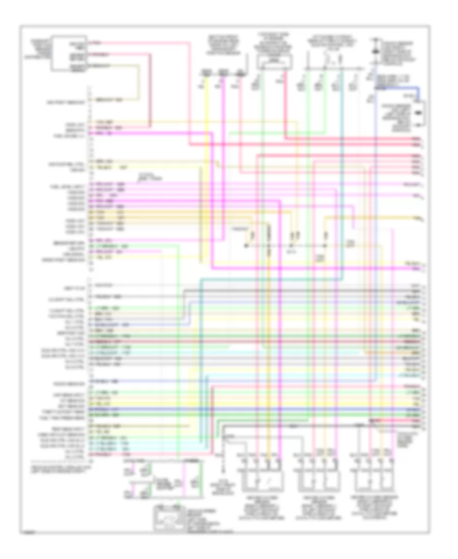
7.4L VIN J, Engine Performance Wiring Diagrams (1 of 4) for GMC CHD 2000 3500
List of elements for 7.4L VIN J, Engine Performance Wiring Diagrams (1 of 4) for GMC CHD 2000 3500:
- (19 cm into oxygen sensor harn)
- (attached to right rear of throttle body) idle air control (iac) valve
- (bottom front of engine near, crank pulley) crankshaft position sensor
- (top right side of engine) evaporative emission canister purge solenoid valve
- 1-2 shift sol ctrl
- 2-3 shift sol ctrl
- A/t w/ 4wd
- Air pump rel ctrl
- Cam posit sens sig
- Camshaft position sensor (inside distributor)
- Crank posit sens sig
- Ect sens sig
- Egr posit sig
- Fuel gauge lvl
- Fuel level input
- Fuel tank press sens
- G119 (right front side of eng block)
- Heated oxygen sensor (bank 1 sensor 1) (in left exhaust pipe in front of catalytic converter)
- Heated oxygen sensor (bank 2 sensor 1) (in right exhaust pipe in front of catalytic converter)
- Heated oxygen sensor (bank 2 sensor 2) (in right exhaust pipe in back of catalytic converter) (california)
- Ho2s low
- Ho2s sig
- Iat sens sig
- Idle air ctrl (iac) a hi
- Idle air ctrl (iac) b lo
- Ign feed
- Inj 1 ctrl
- Inj 2 ctrl
- Inj 3 ctrl
- Inj 4 ctrl
- Inj 5 ctrl
- Inj 6 ctrl
- Inj 7 ctrl
- Inj 8 ctrl
- Inline gender adapter
- Knock sens sig
- Knock sensor (ks) (left) (left side of engine block, below exhaust manifold)
- Knock sensor (ks) (right) (right side of engine block, below exhaust manifold)
- Map sens input
- Mass air flow sens sig
- Nca
- Others
- Pnk
- Pnk c ignition feed
- Pnk pnk
- Pnk pnk pnk pnk
- S114
- S148
- S149
- S162
- Sens rtn
- Sens sig
- Sensor return
- Tan
- Tcc pwm sol ctrl
- Temp sens input
- Throttle posit sens
- Vehicle control module (vcm) (left side of engine compt)
- Vehicle speed sensor (left side of transmission, left side of transfer case w/ 4wd)
- Vent ctlr
- Vss rtn
- Vss sig
- Vss signal
- W/ dual fuel tanks
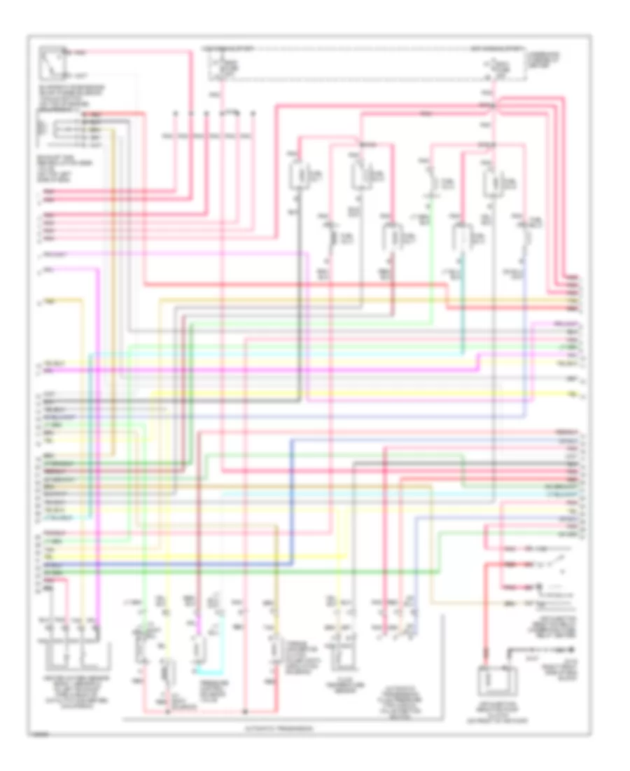
7.4L VIN J, Engine Performance Wiring Diagrams (2 of 4) for GMC CHD 2000 3500
List of elements for 7.4L VIN J, Engine Performance Wiring Diagrams (2 of 4) for GMC CHD 2000 3500:
- 2-3 shift red
- Air injection reaction pump clutch (on front of air pump)
- Air injection reaction relay (underhood fuse/ relay center)
- Automatic transmission
- Automatic transmission fluid pressure (tfp) manual valve position switch
- Ecm1 fuse 20a
- Eng1 k7
- Evaporative emissions (evap) purge solenoid vacuum switch (on top of engine) (california)
- Exhaust gas recirculation (egr) valve (on top left side of eng)
- Fluid temperature sensor
- Fuel inj 1
- Fuel inj 2
- Fuel inj 3
- Fuel inj 4
- Fuel inj 5
- Fuel inj 6
- Fuel inj 7
- Fuel inj 8
- Fuse 20a l8
- G119 (right front side of eng block)
- Heated oxygen sensor (bank 1 sensor 2) (in left exhaust pipe in back of catalytic converter) (california)
- Hot in run & start
- Nca
- Pnk
- Pnk pnk pnk pnk
- Pnk pnk pnk tan red
- Pressure control solenoid valve
- Red
- S104
- S108
- S147
- S154
- S155
- Solenoid
- Tan
- Torque convertor clutch pulse width modulation solenoid
- Underhood fuse/relay center
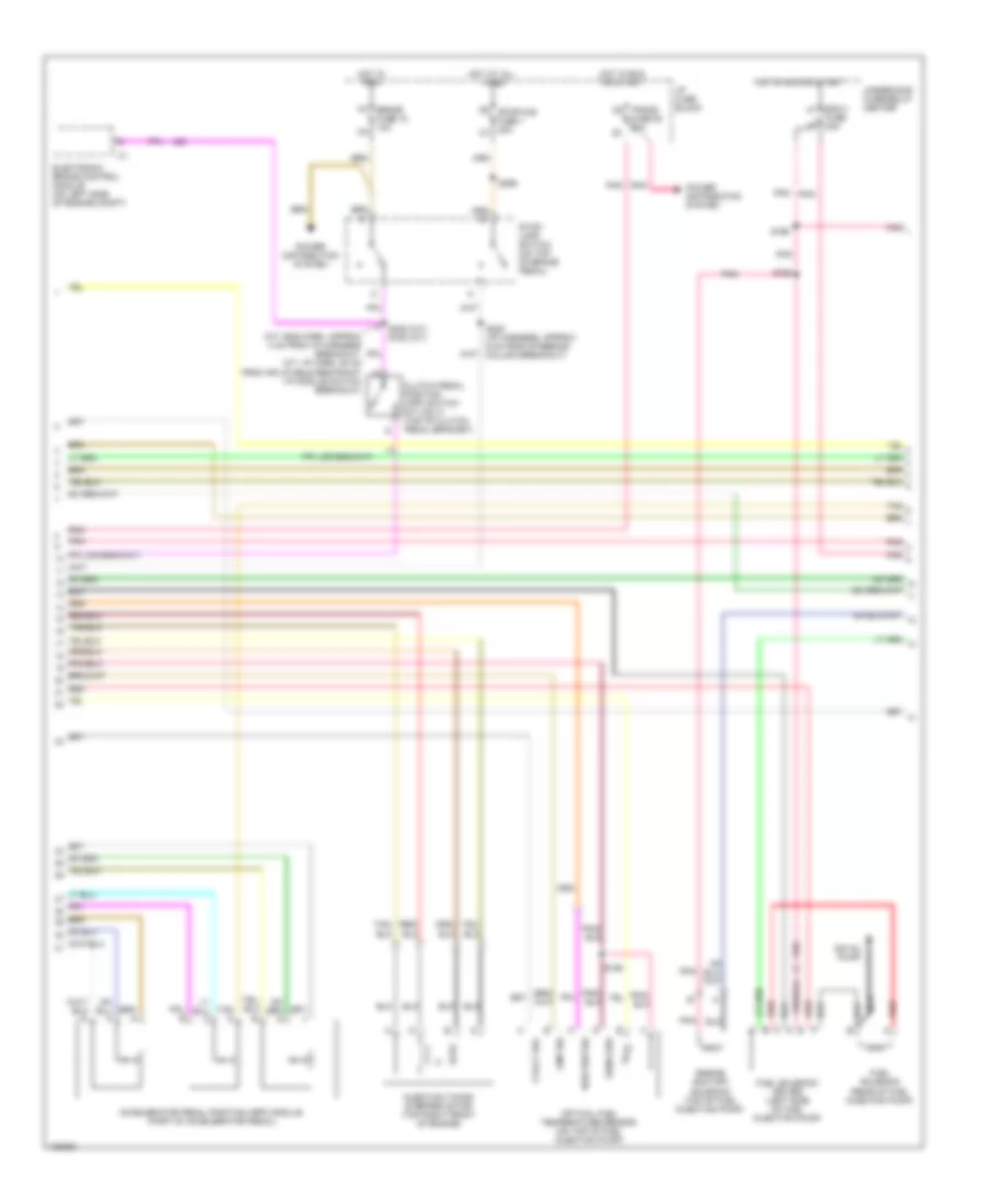
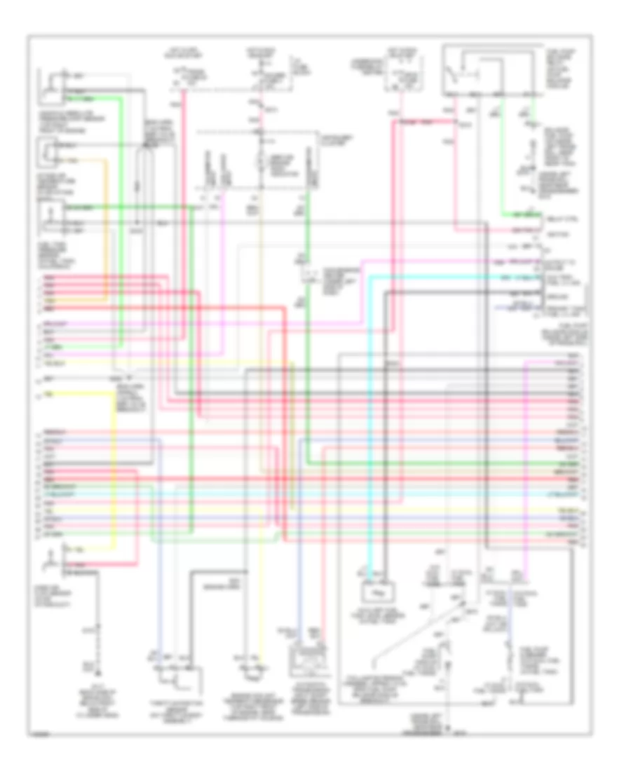
7.4L VIN J, Engine Performance Wiring Diagrams (3 of 4) for GMC CHD 2000 3500
List of elements for 7.4L VIN J, Engine Performance Wiring Diagrams (3 of 4) for GMC CHD 2000 3500:
- (eng harn,
- (eng harn, approx 4 cm from egr valve breakout)
- (engine harn)
- (inside left frame rail, near rear crossmember)
- (inside left frame rail, near rear crossmember) g415
- (taillamp extension harness, approx 10 cm from fuel pump balance module breakout)
- 7 cm from egr valve breakout) s106
- Automatic transmission input shaft speed sensor (left side of transmission)
- Aux tank fuel lvl sig
- Auxiliary fuel tank level sensor (in fuel tank)
- Balance fuel pump (on inside left frame rail, near front of rear tank)
- Convenience center (under left side of dash)
- D w/ dual fuel tanks
- Engine coolant temperature sensor (top right front of engine, near thermostat housing)
- F7 ign e fuse 10a g8
- Fuel gauge input
- Fuel pump & sender (w/o dual fuel tanks) (in fuel tank)
- Fuel pump balance module (inside left side of frame rail)
- Fuel pump balance relay (on fuel pump balance module)
- Fuel pump module (w/ dual fuel tanks)
- Fuel tank pressure sensor (in fuel tank) (california)
- Fuel tanks
- G117 (back side of eng block, below right side of cylinder head)
- G415
- Gauges fuse 4 10a
- Ground
- Hot in off, run or start
- Hot in run or start
- I/p fuse block
- Ignition
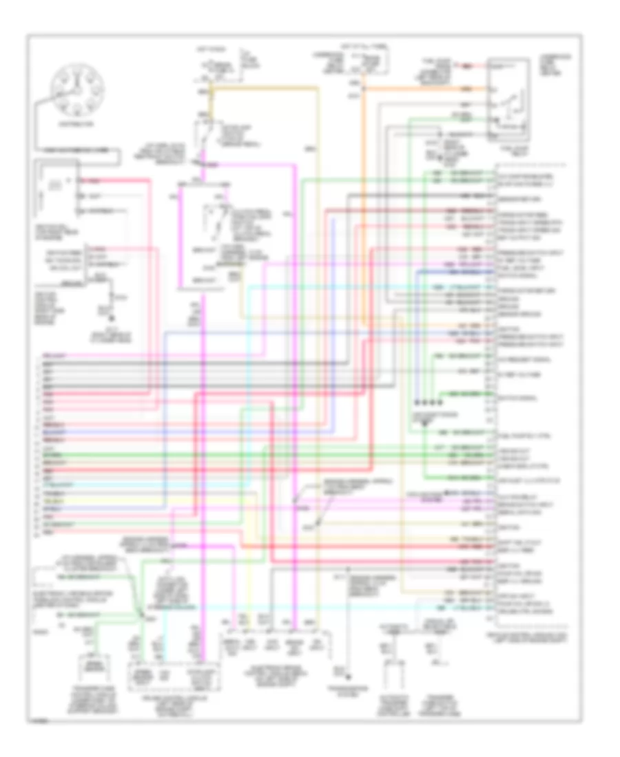
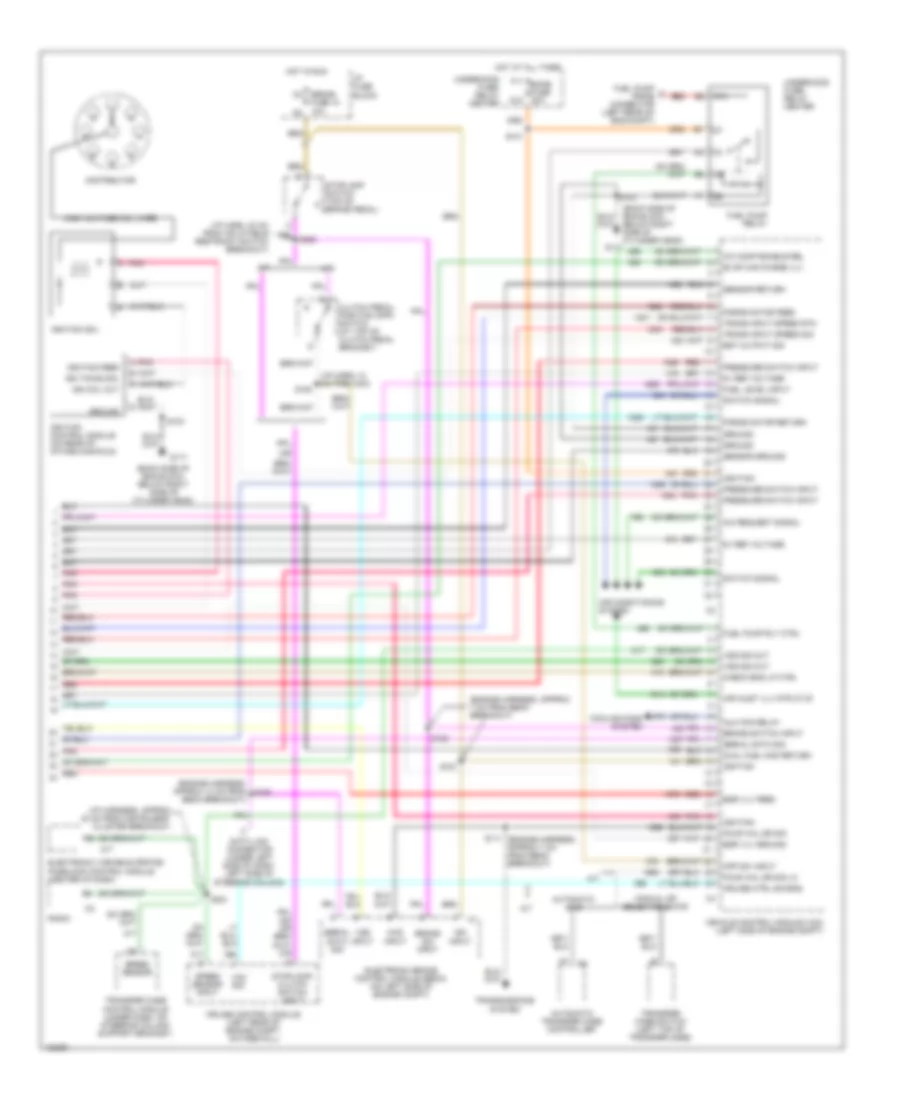
- Instrument cluster
- Intake air temperature sensor (in air intake duct)
- Manifold absolute pressure (map) sensor (top right front of engine)
- Mass air- flow sensor (in air intake duct)
- Output to gauge c2
- Pnk
- Pnk a
- Pnk pnk tan red
- Primary tank fuel lvl sig
- Relay ctrl
- S103
- S146
- S213
- S231
- S232
- S315
- S318
- S319
- S324
- S430
- Service engine soon indicator
- Speedometer input
- Tachometer input
- Tan a
- Throttle position sensor (on throttle body assembly)
- Trans fuse 20 10a
- Underhood fuse/relay center
- W/ dual fuel tank
- W/ dual w/o dual fuel tank
- W/o dual fuel tank
- W/o dual fuel tanks
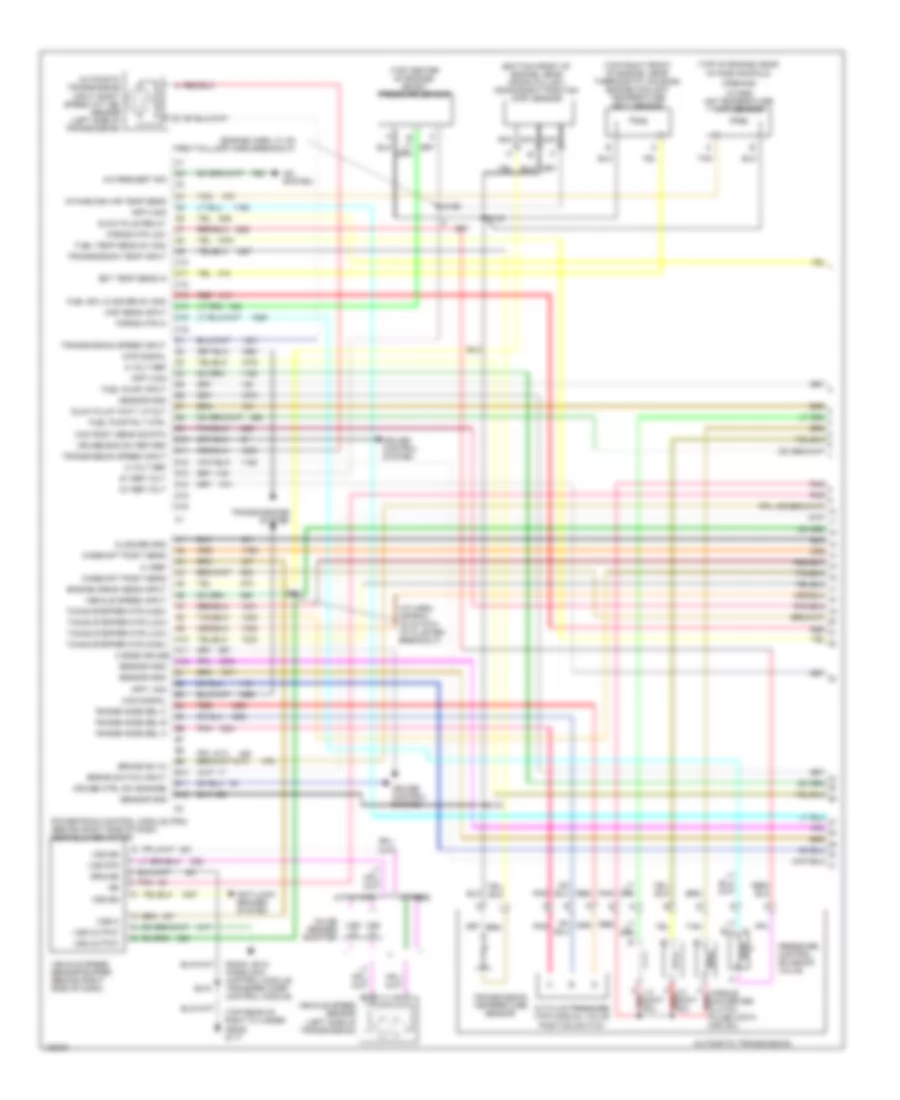
7.4L VIN J, Engine Performance Wiring Diagrams (4 of 4) for GMC CHD 2000 3500
List of elements for 7.4L VIN J, Engine Performance Wiring Diagrams (4 of 4) for GMC CHD 2000 3500:
- (back side of eng block, below right side of cylinder head)
- (engine harness, approx 13 cm from s150
- (engine harness, approx 7 cm from ebcm breakout)
- (i/p harn, 13 cm from ccm)
- (i/p harn, 20 cm from inflatable restraint switch breakout)
- (i/p harness, approx 40 cm from instrument cluster breakout)
- (or
- 4wd input
- 5v ref voltage
- 87a
- A/c comp enable rel
- A/c request signal
- A/t
- Air conditioning system
- Air inlet vlv mtr ctlr
- Automatic 4wd
- Automatic transfer case controller
- Aux fan relay
- Brake sw input
- Brake switch input
- Check eng lp ctrl
- Clutch pedal position (cpp) switch (at top of clutch pedal bracket)
- Cooling fans system
- Cpp sw input
- Cruise control module (left rear of engine compt, on firewall)
- Cruise ctrl sig eng
- Data link connector (under left side of dash, left side of steering column)
- Distributor
- Dual fuel mod return
- Ebcm breakout)
- Egr vlv feed
- Egr vlv ground
- Electronic brake control module (ebcm) (on left side of engine compt)
- Electronic variable orifice/ passlock control module (center of dash)
- Est output sig
- Evap can purge vlv
- F11 ecmb fuse 20a
- Force motor feed
- Force motor return
- Four whl dr sig
- Four whl dr sig lo
- Fuel level input
- Fuel pump a prime connector (left rear of eng compt)
- Fuel pump relay
- Fuel pump rly ctrl
- G117
- G12
- Ground
- High voltage coil wire
- Hot at all times
- Hot in run
- I/p fuse block
- Ign coil out
- Ign input
- Ign timing sig.
- Ignition
- Ignition coil
- Ignition control module (on rear of intake manifold)
- Ignition feed
- M/t
- M4 brake fuse 18 10a n3
- Manual or selectable 4wd
- Pnk
- Pnk a
- Pressure switch input
- Radio
- Red
- S101
- S103
- S111 (engine harness, approx 7 cm from ebcm breakout)
- S151
- S152
- S153
- S221
- Sensor ground
- Sensor return
- Serial data sig
- Speed sensor
- Speed sensor input
- Stoplamp switch (top of brake pedal)
- Stoplamp/ clutch switch input
- Switch signal
- Trans input speed rtn
- Trans input speed sig
- Transfer case control module (under dash, on steering column support bracket)
- Transfer case switch (left top of transfer case)
- Transmissions system
- Underhood fuse/ relay center
- Vcm sig
- Vehicle control module (vcm) (left side of engine compt)
- Vss input
- Vss sig out
EXTERIOR LIGHTS
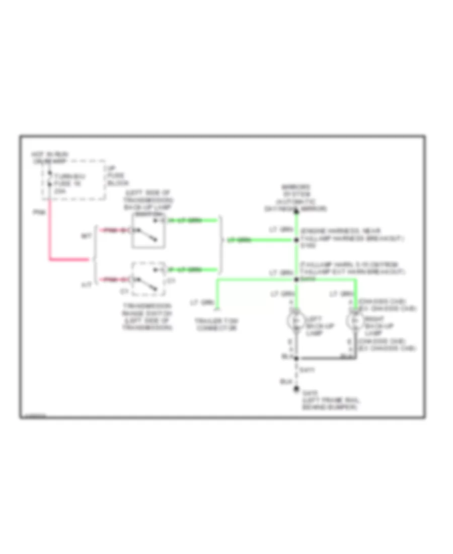
Back-up Lamps Wiring Diagram for GMC CHD 2000 3500
List of elements for Back-up Lamps Wiring Diagram for GMC CHD 2000 3500:
- (chassis cab) a c
- (ex chassis cab)
- (left side of transmission) back-up lamp switch
- A c
- A/t
- G415 (left frame rail, behind bumper)
- Hot in run or start
- I/p fuse block
- Left back-up lamp
- M/t
- Mirrors system (automatic day/night mirror)
- Pnk
- Right back-up lamp
- S411
- S414
- Trailer tow connector
- Transmission range switch (left side of transmission)
- Turn b/u fuse 16 20a
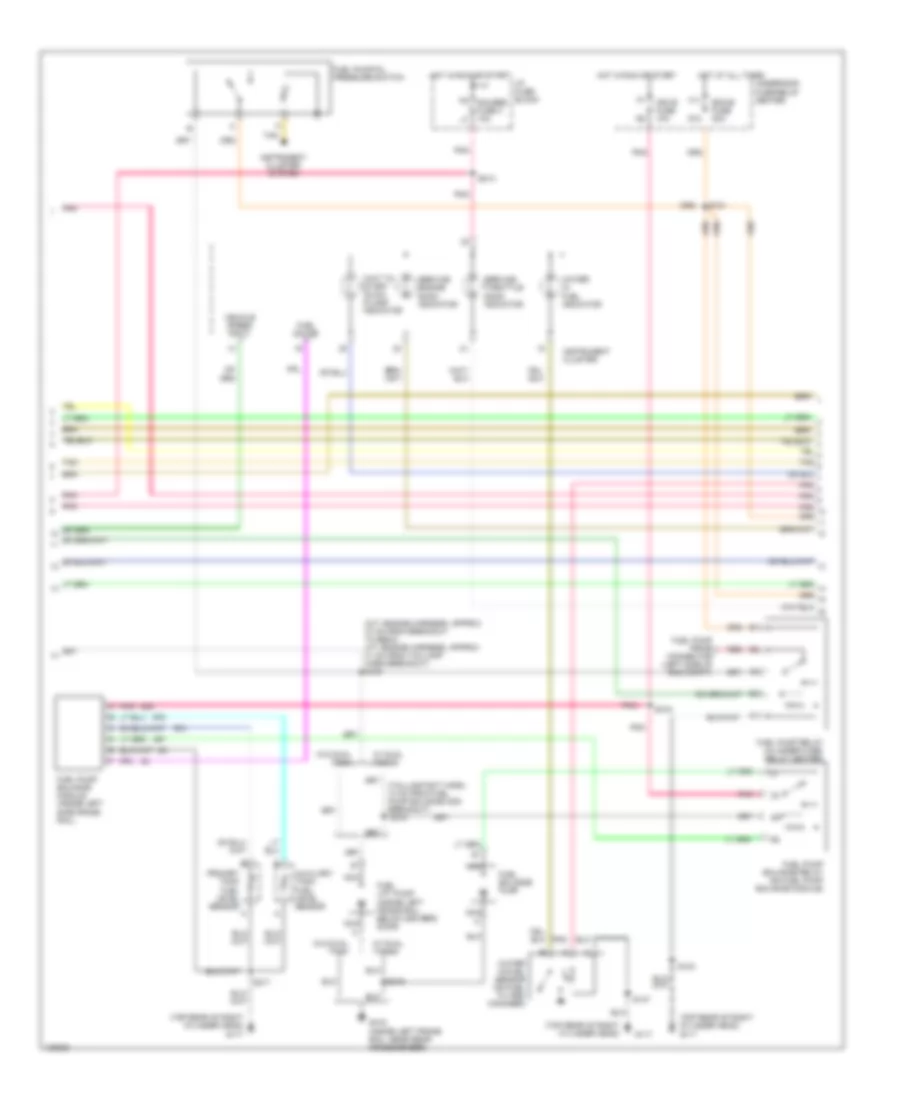
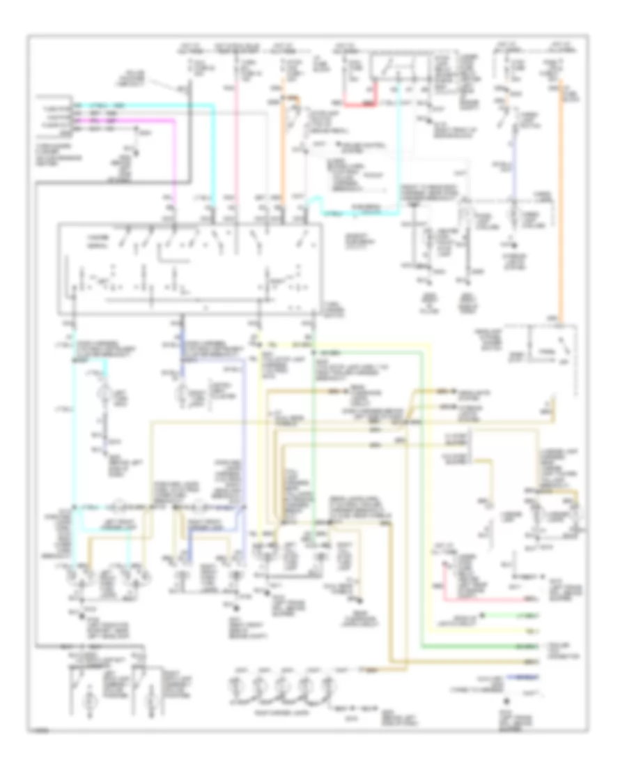
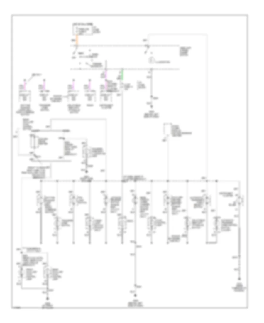
Exterior Lamps Wiring Diagram for GMC CHD 2000 3500
List of elements for Exterior Lamps Wiring Diagram for GMC CHD 2000 3500:
- (dash harness behind left side of dash) s210
- (execpt suburban/ utility)
- (forward lamps harn, 35 cm from wiper harn breakout) s122
- (forward lamps harness, 5 cm from right headlamp breakout) s127
- (front to rear body harness, near chmsl harness breakout)
- (license lamp harness, near license lamp toward taillamp breakout) s415
- (rear lamps harn, 27 cm from trailer harness breakout) (w/ duel rear wheels) s413
- (tail- lamp harness, near taillamps extension harness break- out) s412
- Aux fuse 22 20a
- Auxiliary lead (taped to harness)
- Back-up lights circuit
- Cargo lamp
- Cargo lamp (2 bulbs)
- Cargo lamp switch
- Center high mount stop lamp
- Chmsl lamp (2 bulbs)
- Cruise control system
- Ctsy fuse 20a
- Fuse block
- G108 (left radiator support, near left headlamp)
- G119 (right front of engine block)
- G1o1 (right front side of engine compt)
- G201 (right side of dash)
- G202 (behind left side of dash)
- G305 (right "b" pillar)
- G415 (left frame rail, behind bumper)
- H9 turn pwr h8 haz pwr h7 flshr out g8 gnd
- Hazard
- Headlamp & panel dimmer switch
- Headlights system
- Hot at all times
- Hot in run, bulb test or start
- I/p fuse block
- Instru- ment cluster
- Interior lights system
- Left
- Left front marker lamp
- Left front park/ turn lamps
- Left spotlamp assembly (police package)
- Left tail/ stop/ turn lamp
- Left turn indic
- License lamp
- License lamps
- Maxi fuse 30a
- Nca
- Normal
- Off
- Park
- Park lps fuse 9 20a
- Pickup
- Pnk
- Police package (1999 only)
- Rear clearance lamps circuit
- Red
- Rheo- stat
- Right
- Right front marker lamp
- Right front park/ turn lamps
- Right spotlamp assembly (police package)
- Right tail/ stop/ turn lamp
- Right turn indic
- Roof marker lamps
- S107
- S119 (forward lamps harn, 16 cm from wiper harn breakout)
- S123
- S128
- S204
- S215
- S220 (dash harn, 6 cm from column harness breakout)
- S242
- S259
- S283 (spotlamp ext harness)
- S299
- S316
- S411
- S416
- S419
- S421 (tail/stop lamp harness, 7 cm from g415)
- S422 (tail/stop lamp harn, 7 cm from trailer harness breakout)
- S424
- Stop- lamp relay (except subur- ban/ utility)
- Stop/ haz fuse 1 20a
- Stoplamp switch (top of brake pedal)
- Suburban/ utility
- Trailer tow connector
- Turn- b/u fuse 16 15a
- Turn/ hazard switch
- Turn/hazard flasher (on convenience center)
- Under- hood fuse relay center (left rear of engine compt)
- Under- hood fuse- relay center (left rear of engine compt)
- W/ dual rear wheels
- W/ step bumper
- W/o step bumper
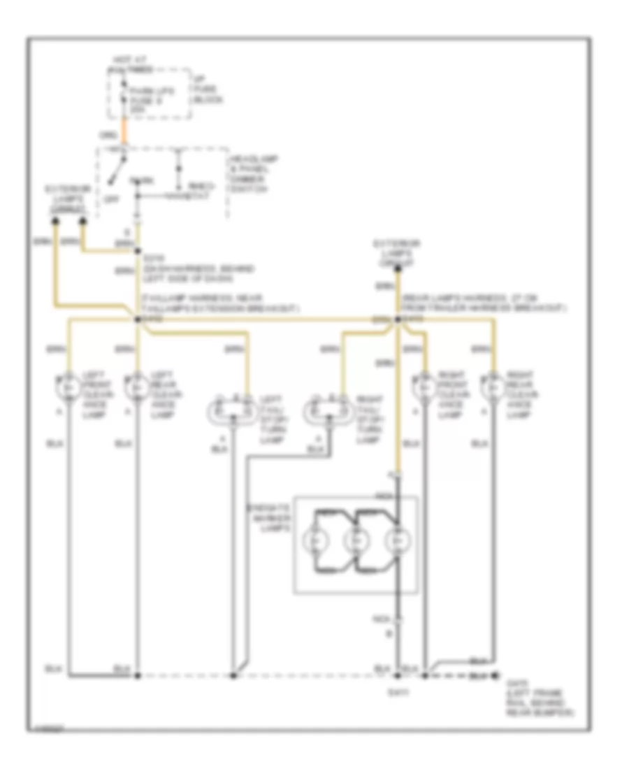
Rear Clearance Lamps Wiring Diagram for GMC CHD 2000 3500
List of elements for Rear Clearance Lamps Wiring Diagram for GMC CHD 2000 3500:
- (rear lamps harness, 27 cm from trailer harness breakout) s413
- (taillamp harness, near taillamps extension breakout) s412
- Endgate marker lamps
- Exterior lamps circuit
- G415 (left frame rail, behind rear bumper)
- Headlamp & panel dimmer switch
- Hot at all times
- I/p fuse block
- Left front clear- ance lamp
- Left rear clear- ance lamp
- Left tail/ stop/ turn lamp
- Nca
- Off
- Park
- Park lps fuse 9 20a
- Rheo- stat
- Right front clear- ance lamp
- Right rear clear- ance lamp
- Right tail/ stop/ turn lamp
- S210 (dash harness, behind left side of dash)
- S411
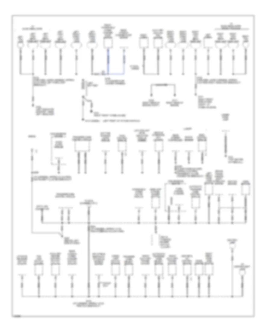
GROUND DISTRIBUTION
Ground Distribution Wiring Diagram (1 of 4) for GMC CHD 2000 3500
List of elements for Ground Distribution Wiring Diagram (1 of 4) for GMC CHD 2000 3500:
- (i/p harness, approx 24 cm from instrument cluster breakout)
- (left front of intake manifold)
- A16
- Ashtray lamp
- Audio alarm module
- Automatic transfer case control module
- Automatic transfer case select switch
- Auxiliary cooling fan motor
- Auxiliary heater control switch (utility)
- Body control module
- Brake trans- mission shift interlock switch
- C10
- Cargo lamp switch (pickup)
- Cigar lighter
- Convenience center
- D10
- D12
- D13
- Data link connector
- Daytime running lamps module
- Fog lamp switch (luxury)
- Front auxiliary power outlet
- Front windshield wiper/ washer pump motor
- G101 (right front side of eng compt, at wheelhousing)
- G101 (right front wheelhouse)
- G105 (right rear of engine compt)
- G108 (left radiator support, near left headlamp)
- G110 (diesel)
- G117 (right rear of engine)
- G121 (top center of firewall)
- G202 (behind left side of dash)
- Ground strap
- Headlamp & panel dimmer switch
- Heater & a/c control switch
- Horn switch
- Hvac control module
- I/p compartment lamp
- Ignition switch
- Inflatable restraint i/p module enable switch
- Key-in warning buzzer switch (luxury)
- Left battery
- Left fog lamp
- Left front door jamb switch
- Left front park/ turn lamp
- Left high beam headlamp
- Left high/ low beam headlamp
- Left horn
- Left low beam headlamp
- Liftgate release switch (utility)
- Low coolant level indicator module (diesel)
- Luxury
- Pickup only
- Radio
- Rear stereo controller
- Rear window washer pump motor
- Rear window wiper/ washer switch (utility)
- Right fog lamp
- Right front door jamb switch
- Right front park/ turn lamp
- Right high beam headlamp
- Right high/ low beam headlamp
- Right horn
- Right low beam headlamp
- S123 (forward lamps harness, approx 23 cm from left park/lamp breakout)
- S128 (forward lamps harness, approx 5 cm from right headlamp breakout)
- S158 (in washer pump jumper harness)
- S204 (i/p harness, approx 10 cm from steering column harn)
- S218 (i/p harness, aprrox 16 cm from dlc breakout)
- S298
- S336 (floor console harn, approx 5 cm from crossbody in-line connector breakout)
- Shock sensor
- Spare
- To s316 (diagram 2 of 4)
- Transfer case control module
- Transfer case select switch
- Turn/ hazard flasher
- Uncoated
- Under- hood lamp
- Vehicle interface unit (luxury)
- W/ dual horns
- W/ quad headlamps
- W/ quad headlamps/ sport package
- Windshield wiper motor module
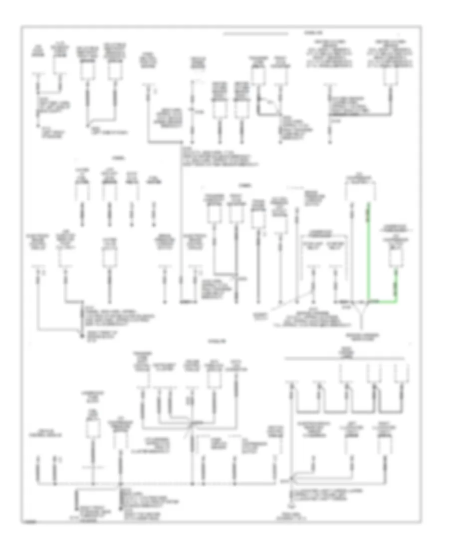
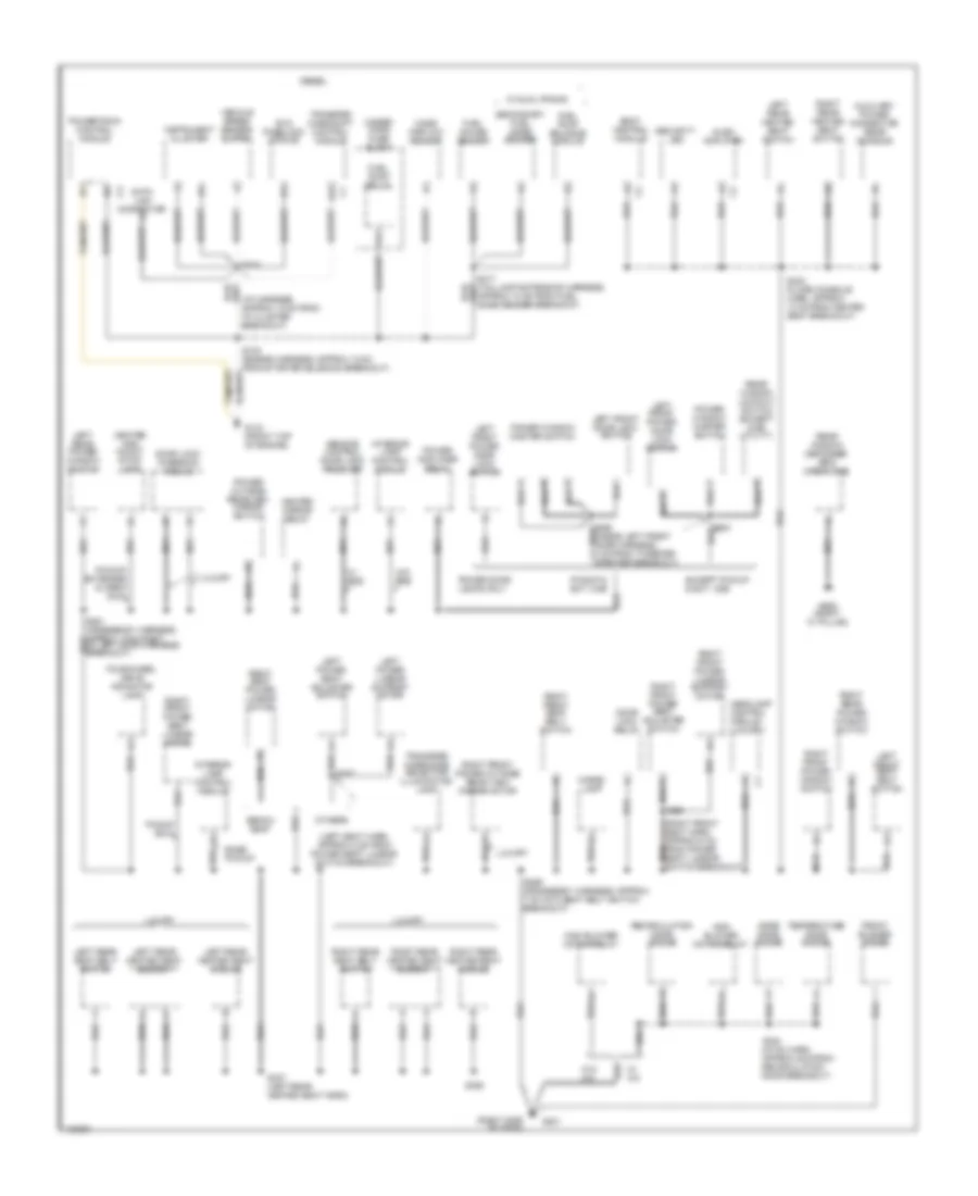
Ground Distribution Wiring Diagram (2 of 4) for GMC CHD 2000 3500
List of elements for Ground Distribution Wiring Diagram (2 of 4) for GMC CHD 2000 3500:
- (4wd harn, approx 10 cm from transfer case relay breakout)
- (eng harn, approx 16 cm into vehicle speed sensor breakout)
- (engine harness, near diode)
- (i/p harness, approx 8 cm from i/p cluster breakout)
- (illuminated vanity mirror jumper, approx 11 cm toward left illuminated vanity mirror)
- (oxygen sensor jumper harn, approx 7 cm from right bank oxygen sensor harn)
- (right front of engine block) g119
- (right front of engine, near thermostat housing)
- 87a
- A.i.r. solenoid check valve
- A/c com- pressor low cutout switch
- A/c compressor clutch
- A/c compressor clutch relay
- A/c compressor cycling switch
- A/c compressor pressure switch
- Air injection reactor pump (7.4l only)
- Air pump motor
- Brake pressure warning switch
- Cruise control module
- Data link connector
- Diesel
- E16
- Electrochromic rearview mirror w/ compass
- Electronic brake control module
- Evo passlock module
- Except utility
- From s204 (diagram 1 of 4)
- Front axle actuator
- Fuel heater
- Fuel pump relay
- G110 (left front of engine)
- G119
- G134 (right top center of cylinder head)
- G202 (left side of dash)
- Gasoline
- Glow plug relay
- Heated oxygen sensor (5.0l: bank 1 sensor 2, 5.7l w/ below 8600 gvw: bank 2 sensor 2, 5.7l w/ over 8600b gvw & 7.4l: bank 1 sensor 2)
- Heated oxygen sensor (5.0l: bank 1 sensor 3, 5.7l w/ below 8600 gvw: bank 1 sensor 2, 5.7l w/ over 8600b gvw & 7.4l: bank 2 sensor 2)
- Heated oxygen sensor bank 1 sensor 1
- Heated oxygen sensor bank 1 sensor 2
- Ignition control module
- Inflatable restraint front end sensor
- Inflatable restraint sensing & diagnostic module
- Instrument cluster
- Left illuminated vanity mirror
- Low coolant level sensor
- Mass airflow sensor
- Park/ neutral position switch
- Right illuminated vanity mirror
- Roof marker lamps
- S103 (eng harn, 5.0l/5.7l: 8 cm from egr, 6.5l/7.4l: 12 cm from starter solenoid breakout)
- S107 (engine harness, 5.0l/5.7l: approx 20 cm egr, 6.5l: approx 40 cm from ebcm, 7.4l: approx 18 cm from ebcm breakout)
- S147 (diesel: eng harn, approx 4 cm from starter motor solenoid, gas: eng harn, approx 5 cm from egr valve breakout)
- S149
- S156
- S162 (5.0l/5.77l: eng harn, 17 cm from starter solenoid breakout, 7.4l: eng harn, approx 15 cm from right bank oxygen sensor breakout)
- S167 (battery harn, at left side of eng compt)
- S185
- S186
- S215
- S302
- S302 (4wd harn, approx 10 cm from transfer case relay breakout)
- S316
- Starter relay
- Stoplamp relay
- Trans range switch
- Transfer case relay
- Transfer case shift control module
- Transfer case shift switch
- Underhood fuse block
- Vehicle control module
- Vehicle speed sensor
- Water in fuel filter
- Water valve (utility)
Ground Distribution Wiring Diagram (3 of 4) for GMC CHD 2000 3500
List of elements for Ground Distribution Wiring Diagram (3 of 4) for GMC CHD 2000 3500:
- (i/p harness, approx 12 cm from i/p cluster breakout)
- (left seat harn, approx 5 cm from power seat lumbar switch breakout)
- (right front seat harn, approx 5 cm from power seat lumbar switch breakout)
- (right side of dash)
- Audio amplifier
- Auxiliary power connector rear console
- Base pickup
- Bench seat
- Body control module
- Cargo lamp
- Center high mount stop- lamp
- Data link connector
- Diesel
- Door lock inversion module
- Door lock relay
- E16
- Evo passlock module
- Except pickup & ext. cab
- Four-wheel drive indicator lamp
- Front blower motor
- Fuel gauge sender
- Fuel pump balance module
- Fuel pump relay
- G134 (front top of engine)
- G201
- G905 (right "c" pillar)
- Headlamp control module (luxury)
- Heated mirror relay
- High blower motor relay
- Instrument cluster
- Interior lamp control module
- Left front door lock switch
- Left front power door lock switch
- Left front seat belt switch
- Left power lumbar support motor
- Left power seat adjuster switch
- Left rear heated seat element
- Left rear heated seat module
- Left rear heated seat switch
- Left rear power window switch
- Left rear seat belt switch
- Luxury
- Mass airflow sensor
- Mode door motor
- Others
- Pickup & ext. cab
- Pickup only
- Pickup/ extended & crew only
- Power amplifier relay
- Power door locks only
- Power outside rearview mirror switch
- Power window master switch
- Powertrain control module
- Rear window defogger grid (crew cab)
- Rear window lockout switch (except 2-dr utility)
- Recirculation door motor
- Remote control door lock receiver
- Right front power lumbar support motor
- Right front power outside rear view mirror motor
- Right front power seat adjuster switch
- Right front power seat lumbar motor
- Right front power window switch
- Right front seat belt switch
- Right rear heated seat element
- Right rear heated seat module
- Right rear heated seat switch
- Right rear power window switch
- Right rear seat belt switch
- Right seat power lumbar motor
- S103 (engine harness, approx 12 cm from starter solenoid breakout)
- S215
- S227
- S228
- S244 (hvac harn, approx 8cm from recirculation door breakout)
- S251 (crossbody harness, approx 13cm right of left door harness breakout)
- S259 (crossbody harness, approx 7 cm into seat belt switch breakout)
- S317 (taillamp extension harness, approx 10 cm from fuel gage sender breakout)
- S330 (floor console harn, approx 13 cm from heated seat breakout)
- S337 (left rear heated seat harn)
- S358
- S500
- S500 (inside left front door harness, 8 cm from tweeter speaker breakout)
- Secondary fuel gage sender
- Security led
- Temperature door motor
- Transfer case mode selector illumination lamp
- Transfer case shift control module
- Under- hood fuse block
- Vehicle speed sensor buffer
- W/ a/c
- W/ dual tanks
- W/ rke
- W/o a/c
- W/o rke
Ground Distribution Wiring Diagram (4 of 4) for GMC CHD 2000 3500
List of elements for Ground Distribution Wiring Diagram (4 of 4) for GMC CHD 2000 3500:
- (auxiliary hvac harn, approx 7 cm from blower motor resistor breakout)
- (diesel)
- (front- to-rear body harn, appr0x 8 cm from chmsl breakout)
- (gas)
- (license lamps harness, approx 8 cm from tail- lamp harness breakout)
- (rear lamps harness, 17-33 cm from taillamps extension breakout)
- (right front seat harn, approx 5 cm from power seat lumbar switch breakout) s321
- Auxiliary blower motor
- Auxiliary heater- a/c logic module
- Auxiliary mode door motor
- Auxiliary temp door motor
- Cargo door lock relay
- Cargo doors
- Center high mount stoplamp
- Chassis cab & heavy duty
- Door lock control module (w/ cargo doors)
- Endgate marker lamps
- Except chassis cab & heavy duty
- Front auxiliary heater-a/c control module
- Front dome lamp
- Fuel pump & sender (primary)
- Fuel pump & sender (secondary)
- G305 (right 'b' pillar)
- G415 (left frame rail, behind bumper)
- G416 (inside left framerail, near rear crossmember)
- Garage door opener
- In-line resistor
- Left cargo door defogger grid
- Left door contact button
- Left front clearance lamp
- Left license lamp
- Left rear clearance lamp
- Left rear tail, stop, license, turn & back-up lamps
- Left rear tail, stop, turn & backup lamps
- Left tail, stop, turn & backup lamps
- Lift gate
- Liftgate release relay
- Liftgate window defogger grid
- Luxury
- Nca
- Pickup w/ dual rear wheels
- Reading lamp overhead console
- Rear auxiliary heater-a/c control module
- Rear auxiliary power connector
- Rear dome lamp
- Rear door jamb switch
- Rear wiper motor module
- Right cargo door defogger grid
- Right door contact button
- Right front clearance lamp
- Right license lamp
- Right rear clearance lamp
- Right rear tail, stop, license, turn & back-up lamps
- Right rear tail, stop, turn & back-up lamps
- Right tail, stop, turn & backup lamps
- S307 (rear hvac control harness, approx 10 cm from hvac logic module breakout)
- S319 (taillamp extension harn, approx 7cm from fuel pump and sender breakout)
- S403
- S410 (front to rear lamps harness, 1213 cm from right rear door speaker breakout)
- S411
- S411 (rear lamps harness, 17-33 cm from taillamps extension breakout)
- S416
- S419
- S424
- Trailer ground (taped back)
- Utility
- W/ dual tanks
HEADLIGHTS
Headlight Wiring Diagram, with Quad Headlamps for GMC CHD 2000 3500
List of elements for Headlight Wiring Diagram, with Quad Headlamps for GMC CHD 2000 3500:
- (except gas: i/p harn, near strng col harn breakout) (gas: i/p harn, near auxiliary power outlet)
- (forward lamps harn, approx 12 cm from left headlamp breakout toward windshield washer pump)
- Acc
- Brake ind ctrl
- Brake warn in
- Bulb test
- Convenience center (under left side of dash)
- Daytime running lamp module (behind left side of dash)
- Daytime running lamps relay
- Diode 203
- Drl indicator
- Drl relay ctrl
- Drl-fog fuse 15 20a
- Exterior lights system
- Fog lamp relay
- Fog lamp switch
- G101 (right front side of engine compartment)
- G108 (left radiator support)
- G134 (right top center of cylinder head)
- G202 (behind left side of dash)
- Gauges fuse 4 10a
- Ground
- Head
- Head- lamp dimmer switch
- Headlamp & panel dimmer switch
- High beam indicator
- Hot at all times
- Hot in run, bulb test or start
- I/p fuse block (left side of dash)
- Ignition
- Ignition switch
- Illum lamp
- Ind bulb chk
- Instrument cluster
- Instrument cluster system (brake warning indicator)
- Interior lights system
- Lamp feed
- Left fog lamp
- Left high beam head- lamp
- Left low beam head- lamp
- Lighting fuse 8 50a
- Lock
- Nca
- Off
- On indicator
- Park
- Park brake sig
- Park brake warning switch
- Pk lps fuse 9 20a
- Pnk
- Red
- Red c
- Right fog lamp
- Right high beam head- lamp
- Right low beam head- lamp
- Run
- S120 (forward lamps harn, near windshield washer pump breakout, toward left hdlp)
- S121
- S123
- S126
- S128
- S204
- S205
- S210
- S213
- S215
- S218
- S225 (i/p harn, approx 12 cm from radio harn breakout)
- S298
- Start
- Tan
- Underhood fuse block (left rear of engine compt)
- W/ fog lamps
Headlight Wiring Diagram, with Sealed Beam Headlamps for GMC CHD 2000 3500
List of elements for Headlight Wiring Diagram, with Sealed Beam Headlamps for GMC CHD 2000 3500:
- (except gas: i/p harn, near strng col harn breakout) (gas: i/p harn, near auxiliary power outlet)
- (forward lamps harn, approx 12 cm from left headlamp breakout toward windshield washer pump)
- (high)
- (low)
- A (high)
- A (low)
- Acc
- Brake ind ctrl
- Brake warn in
- Bulb test
- Convenience center (under left side of dash)
- Daytime running lamp module (behind left side of dash)
- Daytime running lamps relay
- Diode 203
- Drl indicator
- Drl relay ctrl
- Drl-fog fuse 15 20a
- Exterior lights system
- Fog lamp relay
- Fog lamp switch
- G101 (right front side of engine compartment)
- G108 (left radiator support)
- G134 (right top center of cylinder head)
- G202 (behind left side of dash)
- Gauges fuse 4 10a
- Ground
- Head
- Head- lamp dimmer switch
- Headlamp & panel dimmer switch
- High beam indicator
- Hot at all times
- Hot in run, bulb test or start
- I/p fuse block (left side of dash)
- Ignition
- Ignition switch
- Illum lamp
- Ind bulb chk
- Instrument cluster
- Instrument cluster system (brake warning indicator)
- Interior lights system
- Lamp feed
- Left fog lamp
- Left head- lamp
- Lighting fuse 8 50a
- Lock
- Nca
- Off
- On indicator
- Park
- Park brake sig
- Park brake warning switch
- Pk lps fuse 9 20a
- Pnk
- Red
- Red c
- Right fog lamp
- Right head- lamp
- Run
- S120 (forward lamps harn, near windshield washer pump breakout toward left headlamp)
- S121
- S123
- S126
- S128
- S204
- S205
- S210
- S213
- S215
- S218
- S225 (i/p harn, approx 12 cm from radio harn breakout)
- S298
- Start
- Tan
- Tan c
- Underhood fuse block (left rear of engine compt)
- W/ fog lamps
HORN
Horn Wiring Diagram for GMC CHD 2000 3500
List of elements for Horn Wiring Diagram for GMC CHD 2000 3500:
- (inside left door harness, approx 25 cm to outside mirror breakout) s124
- A11
- Base
- Body control module (in center console)
- C1 c9
- C210
- C266
- Convenience center (under left side of dash)
- G101 (right front of engine compt, at wheelhousing)
- G202 (behind left side of dash, below fuse box)
- Horn fuse 20a
- Horn relay
- Horn slip ring
- Horn switch
- Hot at all times
- Left horn (front of vehicle)
- Luxury
- Remote control door lock receiver (behind center of dash)
- Right horn (w/ front end appearance package only) (front of vehicle)
- S113
- S128
- S204
- Steering wheel
- Underhood fuse block
- Underhood fuse block (left rear of engine compt)
- Vehicle interface unit receiver (under- neath right rear seat)
INSTRUMENT CLUSTER
5.7L
5.7L VIN R, Instrument Cluster Wiring Diagram for GMC CHD 2000 3500
List of elements for 5.7L VIN R, Instrument Cluster Wiring Diagram for GMC CHD 2000 3500:
- (6 bulbs)
- (engine harn)
- (taillamp extension harn, approx 10 cm from breakout to ground at left side framerail)
- (taillamp extension harn, approx 6 cm from fuel pump harness breakout)
- 39 (or 1020)
- 5v ref
- 7.4l vin j only
- A/t
- A/t w/4wd
- Accy
- Air bag ind
- Anti- lock brakes ind
- Anti-lock brakes system
- Anti-theft system
- Bat ind
- Brake ind
- Brake pressure warning switch (on underside of electronic brake control module)
- Brake psi
- Check gauges ind
- Check gauges lamp driver
- Convenience center
- Daytime running lamps ind
- Daytime running lamps module (behind left side of dash, taped to panel wiring harness)
- Electronic brake control module (ebcm) (on left side of engine compt)
- Engine controls system (fuel pump balance relay)
- Engine coolant temperature sender (left cylinder head, near 1 spark plug)
- Exterior lights system
- Fuel
- Fuel gauge
- Fuel in
- Fuel pump & sender (in fuel tank)
- Fuel pump balance module (inside left side of frame rail)
- Fuel pump/ oil pressure switch & sender (rear top center of engine)
- Fuel ret
- Fuel tank
- G119 (right front of engine block)
- G134 (right top center of cylinder head)
- Gauges fuse 4 10a
- Headlights system
- Hi beam ind
- Hot in run or start
- Hot in run, bulb test or start
- I/p fuse block
- Ign
- Ign e mini fuse 10a
- Ign sw
- Ignition coil (top left rear of engine)
- Ignition switch
- Illumination
- Instrument cluster
- Interior lights system
- Led dimming
- Left turn ind
- Lock
- M/t
- M/t w/4wd & all w/2wd
- Malfunc- tion indicator lamp (service engine soon)
- Mil ind
- Nca
- Off
- Oil gauge
- Parity prndl
- Park brake switch (on park brake pedal bracket)
- Pk brake
- Pnk
- Prndl
- Prndl a
- Prndl b
- Prndl c
- Right turn ind
- Run
- S103
- S147
- S162
- S213
- S215
- S232
- S315
- S324
- S325 (cali)
- S430
- Safety belt ind
- Secondary fuel gauge sender (in rear fuel tank)
- Security ind
- Sens rtrn
- Single dual fuel tanks
- Speedo
- Speedometer
- Start
- Starting/charging system
- Tach
- Tan
- Temp gauge
- Trans fuse 20 10a
- Transmission range switch (left side of transmission)
- Twisted pair
- Underhood fuse block
- Upshift ind
- Upshift ind (m/t only)
- Vehicle control module (vcm) (left side of engine compt)
- Vehicle speed sensor (left side of transmission, left side of tran- sfer case w/ 4wd)
- Vehicle speed sensor (vss) adapter
- Voltmeter
- Vss
- Warning systems
6.5L
6.5L VIN F, Instrument Cluster Wiring Diagram (1 of 2) for GMC CHD 2000 3500
List of elements for 6.5L VIN F, Instrument Cluster Wiring Diagram (1 of 2) for GMC CHD 2000 3500:
- (6 bulbs)
- 39 (or 1020)
- Air bag ind
- Anti- lock brakes ind
- Anti-lock brakes system
- Anti-theft system
- Bat ind
- Brake ind
- Check gauges ind
- Check gauges lamp driver
- Daytime running lamps ind
- Dimming led
- Engine controls system
- Engine coolant temperature sensor (on top right front of engine, near thermostat housing)
- Exterior lights system
- Fuel gauge
- Fuel pump/ oil pressure switch & sender (under intake manifold, center of engine)
- G119 (right front of engine block)
- G134 (front top of engine)
- G202 (behind left side of dash)
- Generator
- Gnd
- Headlights system
- Hi beam ind
- Ign
- Illumination
- Instrument cluster
- Interior lights system
- Left turn ind
- Low coolant ind
- Low coolant level indicator module (behind center of dash)
- Low coolant level switch (in coolant reservoir, right side of engine compt)
- Oil press
- Pnk
- Prndl
- Prndl a
- Prndl b
- Prndl c
- Prndl parity
- Right turn ind
- S107
- S147
- S215
- S298
- Safety belt ind
- Security ind
- Service engine soon ind
- Service throttle soon ind
- Solid state
- Speed- ometer
- Starting/charging system
- Tach
- Tan
- Temp gauge
- Transmission range switch (left side of transmission)
- Volt- meter
- Wait to start ind
- Warning systems
- Water in fuel ind
- Water-in fuel sensor (on fuel filter/ manager)
6.5L VIN F, Instrument Cluster Wiring Diagram (2 of 2) for GMC CHD 2000 3500
List of elements for 6.5L VIN F, Instrument Cluster Wiring Diagram (2 of 2) for GMC CHD 2000 3500:
- (i/p harn, 16 cm into cluster breakout)
- 4wd a/t
- 4wd m/t & all 2wd
- A/t
- Accy
- Anti-lock brakes system
- Brake ind
- Brake pressure warning switch (on rear of ebcm casting)
- Brake psi
- Daytime running lamps module (behind left side of dash, taped to panel wiring harness)
- Dual fuel tanks
- Electronic brake control module (ebcm) (on left side of engine compt)
- Eng 1 mini fuse 20a
- Engine controls system
- Engine controls system (fuel pump balance relay)
- Fuel gauge sender (in front fuel tank)
- Fuel pump & sender
- Fuel pump balance module (inside left side of frame rail)
- Fuse/relay block (left rear of engine compt)
- G119 (right front of engine block)
- G134 (front top of engine)
- Gauges fuse 4 10a
- Hot in run or start
- Hot in run, bulb test or start
- I/p fuse block (under left side of dash)
- Ign e mini fuse 10a
- Ign sw
- Ignition switch
- Lock
- M/t
- Nca
- Off
- Park brake switch (on park brake pedal bracket)
- Pk brake
- Pnk
- Radio
- Run
- S103
- S107
- S108
- S211
- S213
- S215
- S315
- S317
- Secondary fuel gauge sender (in rear fuel tank)
- Single fuel tank
- Start
- Trans fuse 20 10a
- Twisted pair
- Vehicle speed sensor (left side of transmission, left side of transfer case w/ 4wd)
- Vehicle speed sensor (vss) adapter
- Vehicle speed sensor buffer (behind right side of dash)
7.4L
7.4L VIN J, Instrument Cluster Wiring Diagram for GMC CHD 2000 3500
List of elements for 7.4L VIN J, Instrument Cluster Wiring Diagram for GMC CHD 2000 3500:
- (6 bulbs)
- (engine harn)
- (taillamp extension harn, approx 10 cm from breakout to ground at left side framerail)
- (taillamp extension harn, approx 6 cm from fuel pump harness breakout)
- 39 (or 1020)
- 5v ref
- 7.4l vin j only
- A/t
- A/t w/4wd
- Accy
- Air bag ind
- Anti- lock brakes ind
- Anti-lock brakes system
- Anti-theft system
- Bat ind
- Brake ind
- Brake pressure warning switch (on underside of electronic brake control module)
- Brake psi
- Check gauges ind
- Check gauges lamp driver
- Convenience center
- Daytime running lamps ind
- Daytime running lamps module (behind left side of dash, taped to panel wiring harness)
- Electronic brake control module (ebcm) (on left side of engine compt)
- Engine controls system (fuel pump balance relay)
- Engine coolant temperature sender (left cylinder head, near 1 spark plug)
- Exterior lights system
- Fuel
- Fuel gauge
- Fuel in
- Fuel pump & sender (in fuel tank)
- Fuel pump balance module (inside left side of frame rail)
- Fuel pump/ oil pressure switch & sender (rear top center of engine)
- Fuel ret
- Fuel tank
- G119 (right front of engine block)
- G134 (right top center of cylinder head)
- Gauges fuse 4 10a
- Headlights system
- Hi beam ind
- Hot in run or start
- Hot in run, bulb test or start
- I/p fuse block
- Ign
- Ign e mini fuse 10a
- Ign sw
- Ignition coil (top left rear of engine)
- Ignition switch
- Illumination
- Instrument cluster
- Interior lights system
- Led dimming
- Left turn ind
- Lock
- M/t
- M/t w/4wd & all w/2wd
- Malfunc- tion indicator lamp (service engine soon)
- Mil ind
- Nca
- Off
- Oil gauge
- Parity prndl
- Park brake switch (on park brake pedal bracket)
- Pk brake
- Pnk
- Prndl
- Prndl a
- Prndl b
- Prndl c
- Right turn ind
- Run
- S103
- S147
- S162
- S213
- S215
- S232
- S315
- S324
- S325 (cali)
- S430
- Safety belt ind
- Secondary fuel gauge sender (in rear fuel tank)
- Security ind
- Sens rtrn
- Single dual fuel tanks
- Speedo
- Speedometer
- Start
- Starting/charging system
- Tach
- Tan
- Temp gauge
- Trans fuse 20 10a
- Transmission range switch (left side of transmission)
- Twisted pair
- Underhood fuse block
- Upshift ind
- Upshift ind (m/t only)
- Vehicle control module (vcm) (left side of engine compt)
- Vehicle speed sensor (left side of transmission, left side of tran- sfer case w/ 4wd)
- Vehicle speed sensor (vss) adapter
- Voltmeter
- Vss
- Warning systems
INTERIOR LIGHTS
Courtesy Lamps Wiring Diagram, Old Style for GMC CHD 2000 3500
List of elements for Courtesy Lamps Wiring Diagram, Old Style for GMC CHD 2000 3500:
- (crossbody harn, approx 22 cm from left door harn breakout)
- (i/p harn, approx 6 cm from i/p compt box lamp breakout) s208
- (w/ rke)
- Bat
- Braided ground strap
- Cargo door jamb switch (suburban/ utility only)
- Courtesy lamps
- Ctrl
- Ctsy fuse 3 20a
- Dome defeat
- Dome lamp defeat
- Door jamb
- Door lock control module (in front of left rear wheelwell)
- Front dome/ reading lamps
- G201 (right side of dash)
- G202 (behind left side of dash)
- G305 (right "b" pillar)
- Gages fuse 4 10a
- Gnd
- Headlamp & panel dimmer switch
- Horn fuse 20a
- Hot at all times
- Hot in run, bulb test or start
- I/p compart- ment box lamp
- I/p fuse block
- Ign sw
- Interior lamp control module (under center of dash)
- Lamp out
- Left
- Left front door courtesy lamp (if equipped)
- Left front door jamb switch
- Left i/p courtesy lamp
- Left illuminated vanity mirror
- Left rear door courtesy lamp (if equipped)
- Mirrors system
- Nca
- Overhead console lamps circuit
- Pnk
- Pnk a
- Pnk j
- Rear dome/ reading lamps (if equipped)
- Rear door jamb switch (if equipped)
- Remote control door lock receiver (behind center of dash)
- Right
- Right front door courtesy lamp (if equipped)
- Right front door jamb switch
- Right i/p courtesy lamp
- Right illuminated vanity mirror
- Right rear door courtesy lamp (if equipped)
- S113
- S204
- S209 (i/p harn, approx 13 cm from i/p compt box lamp breakout)
- S213
- S218
- S242
- S246
- S248
- S251
- S262 (crossbody harn, approx 19-25 cm from seat belt switch breakout)
- S312
- S316
- S410
- S417 (4 door) (2 door) (front to rear (front to body harn, rear body approx 20 cm harn, approx into crossbody 34 cm from front harn dome lamp breakout) breakout)
- S426
- Underhood fuse/relay center
- Underhood lamp
- W/ overhead console
- W/ rke
- W/o overhead console
- W/o rke
Instrument Illumination Wiring Diagram, Old Style (1 of 2) for GMC CHD 2000 3500
List of elements for Instrument Illumination Wiring Diagram, Old Style (1 of 2) for GMC CHD 2000 3500:
- (behind left side of dash)
- (crossbody harn, approx 6 cm in left door harn breakout)
- (floor console harn, 12 cm from cd player harn breakout) s333
- (right side of dash)
- Ash tray lamp
- Body control module (in center console)
- Exterior lights system
- G201
- G202
- G305 (right "b" pillar)
- Garage door opener lamp
- Headlamp & panel dimmer switch
- Hot at all times
- I/p fuse block
- Left front power window switch
- Left rear heated seat switch
- Left rear power window switch
- Off
- Parade mode sw
- Park
- Park lps fuse 9 20a
- Power outside rearview mirror switch
- Rear stereo controller
- Rear window lockout switch
- Rheo- stat
- Right front power window switch
- Right rear heated seat switch
- Right rear power window switch
- S210 (i/p harn, approx 12 cm from steering column harn breakout)
- S218
- S247
- S251
- S259
- S321
- S330
- S336
- S500
- S502 (left front door harn, near tweeter)
Instrument Illumination Wiring Diagram, Old Style (2 of 2) for GMC CHD 2000 3500
List of elements for Instrument Illumination Wiring Diagram, Old Style (2 of 2) for GMC CHD 2000 3500:
- (6) bulbs
- (behind left side of dash)
- (front to rear body harn, 5 cm from auxiliary hvac fan switch breakout)
- (i/p harn, near i/p cluster breakout) s217
- Audio alarm module (on convenience center)
- Automatic transfer case control switch (luxury) c1
- Automatic transfer cash select switch
- Auxiliary heater control switch (subur- ban/ utilitiy only)
- Base
- Cargo lamp switch (pickup only)
- Conven- ience center
- Daytime running lamp (drl)/ radio override switch
- Daytime running lamps (drl)/ radio override switch
- Display dim sig
- Fog lamp switch
- Front auxiliary hvac control lamp
- G131 (near thermostat housing)
- G201 (right side of dash)
- G202
- G305 (at right "b" pillar)
- Headlamp & panel dimmer switch
- Hot at all times
- Hvac control lamp
- I/p fuse block
- Illum fuse 14 10a
- Illumination
- Inflatable restaint i/p module switch
- Instrument cluster
- Liftgate release switch (subur- ban/ utilitiy only)
- Luxury
- Off
- Parade mode sw
- Park
- Park lps fuse 9 20a
- Pickup/ extended cab only
- Radio
- Rear auxiliary hvac control lamp
- Rear auxiliary hvac control switch
- Rear window wiper/ washer switch (subur- ban/ utilitiy only)
- Rheo- stat
- S204
- S215
- S216 (i/p harn, near i/p cluster breakout)
- S218
- S253 (cross- body harn, near i/p harn breakout)
- S259
- S307
- S310
- Suburban & utility only
- Transfer case shift illumination lamp
- Transfer case switch
- Z56 only
Overhead Console Lamps Wiring Diagram, Old Style Base for GMC CHD 2000 3500
List of elements for Overhead Console Lamps Wiring Diagram, Old Style Base for GMC CHD 2000 3500:
- (front to rear body harn, approx 34 cm from front dome lamp breakout) (2 door) s417
- (under center of dash) (w/o rke) interior lamp control module
- Courtesy lamps
- Courtesy lamps circuit
- Ctsy fuse 3 20a
- Front dome/ reading lamps
- G202 (behind left side of dash)
- G305 (right "b" pillar)
- Headlamp & panel dimmer switch
- Hot at all times
- I/p fuse block
- Int lamp output
- Int lamp output c1
- Overhead console reading lamps
- Rear dome/ reading lamps
- Remote control door lock receiver (w/rke) (behind center of dash)
- S204
- S209 (i/p harn, approx 13 cm from i/p compt lamp breakout)
- S246 (crossbody harn, approx 22 cm from left door harn breakout)
- S320
- S321
- S410
- S426
POWER DISTRIBUTION
Power Distribution Wiring Diagram (1 of 5) for GMC CHD 2000 3500
List of elements for Power Distribution Wiring Diagram (1 of 5) for GMC CHD 2000 3500:
- (crossbody harn, approx 22 cm from left door harness breakout)
- (diesel-eng harn, 6.5cm from ebcm breakout gasoline-eng harn, 12cm from ebcm breakout)
- (eng harn, approx 19cm from electronic brake control module breakout) s113
- (i/p harn, near steering column harness breakout) s205
- (overhead console harn, between garage door opener & reading lamp)
- (stud a)
- (stud b)
- (vanity mirror jumper harn, approx 4 cm from inside rearview mirror)
- 175a
- 7.4l
- A nca
- A/c comp fuse 10a
- A/c compressor clutch relay
- Abs fuse 4 60a
- Aux fan fuse 30a
- Aux pwr auto headlap fuse 22 20a
- Auxiliary cooling fan relay
- Blower fuse 3 50a
- Body control module (bcm)
- Brake lamp relay
- C13
- Camp/trail fuse 30a
- Cargo lamp switch
- Convenience center
- Ctsy fuse 3 20a
- D13
- Daytime running lamps relay
- Diode
- Drl/fog fuse 15 20a
- Dual battery
- Ecm-b fuse 20a
- Electronic brake control module
- Evo/ passlock module
- Front dome lamp
- Front dome lamps
- Fuel pump oil pressure switch
- Fuel pump relay
- Fusible link (5 ga-rust)
- Garage door opener
- Generator (base)
- Generator (uplevel)
- Headlamp & panel dimmer switch
- Headlamp and panel dimmer switch
- Headlamp control module
- Heater mirror relay
- High blower motor relay
- Horn fuse 20a
- Horn relay
- Htd mir fuse 10a
- Hvac control module
- I/p compartment box lamp
- I/p fuse block
- Interior lamp control module
- Left battery (diesel)
- Left courtesy lamp
- Left front door courtesy lamp
- Left rear door courtesy lamp
- Left vanity mirror
- Lighting fuse 8 50a
- Luxury only
- Mega fuse block
- Overhead console reading lamps
- Pickup only
- Pk lps fuse 9 20a
- Power outside rearview mirror switch
- Powertrain control module (diesel)
- Rear dome lamps
- Red
- Remote battery stud
- Right battery
- Right courtesy lamp
- Right front door courtesy lamp
- Right rear door courtesy lamp
- Right vanity mirror
- Rr defog fuse 30a
- S101
- S242 (i/p harn, 12cm from inflatable restraint switch breakout)
- S248 (crossbody harn, approx 35 cm from left front door harn breakout)
- S312 s312
- S325
- S426
- S443
- Security/ strg fuse 21 10a
- Seo fuse 30a
- Single battery (base)
- Single battery (uplevel)
- Spare power source
- Starter motor solenoid
- Stop fuse 2 50a
- To fusible link (diagram 5 of 5)
- To underhood fuse block (diagram 2 of 5)
- Underhood fuse block
- Underhood lamp
- Vehicle control module (gasoline)
- W/o rear auxiliary heater or a/c
- W/o rke
Power Distribution Wiring Diagram (2 of 5) for GMC CHD 2000 3500
List of elements for Power Distribution Wiring Diagram (2 of 5) for GMC CHD 2000 3500:
- (2dr w/ rke & 4dr)
- (crossbody harn, 20 cm from convenience center breakout) s255
- (crossbody harn, approx 19 cm from conenience center)
- (front-to-rear body harn, approx 6 cm from convenience center breakout)
- (i/p harn, 12cm from steering column harness breakout) s200
- (i/p harn, 4cm from auxiliary power outlet breakout)
- (i/p harn, 4cm from steering column harness breakout)
- (i/p harn, approx 10 cm into steering column harn breakout)
- (i/p harn, left rear of engine compartment)
- (luxury only)
- (power lumbar seat jumper harn, approx 13 cm from right power seat breakout)
- (utility only)
- 30a (others)
- 8cm from i/p cluster breakout) s264
- Audio alarm module
- Audio amplifier
- Automatic
- Automatic transfer case
- Automatic transfer case control module
- Aux/pwr fuse 7 25a
- Base
- Base cargo door
- Base cargo doors/upper level liftgate
- Base liftgate/ upper level cargo doors
- Battery fuse 7 50a
- Cargo door lock relay
- Cig ltr fuse 13 20a
- Cigar lighter
- Convenience center
- D14
- D15
- Data link connector
- Door lock control module
- Door lock relay
- Electric
- From underhood fuse block (diagram 1 of 5)
- Front auxiliary power connector
- G202 (left side of dash)
- I/p fuse block
- Left front door lock switch
- Left front power lumbar seat switch
- Left power seat adjuster switch
- Liftgate release relay
- Liftgate release switch
- Luxury level
- Luxury only
- Non- base
- Others
- Pickup
- Pickups w/o rke
- Power amplifier relay (suburban)
- Pwr-accy circuit breaker a (regular 20a cab/extended cab/luxury)
- Radio
- Radio batt fuse 19 10a
- Rear auxiliary power connector (luxury)
- Rear console auxiliary power connector (luxury)
- Rear door lock switch
- Red
- Remote control door lock receiver
- Remote control door lock receiver (uplevel speakers)
- Right front door lock switch
- Right front power lumbar seat switch
- Right front power seat lumbar switch
- Right lumbar power seat switch
- Right power seat adjuster switch
- S212
- S218
- S236
- S237
- S255
- S256
- S272
- S299
- S300
- S434
- Stop lamp switch
- Stop/haz fuse 1 20a
- Suburban/ utility
- T case fuse 2 20a
- To underhood fuse block (diagram 3 of 5)
- Transfer case control module
- Turn/ hazard switch
- Underhood fuse block
- Vehicle interface unit
- W/ rke
- W/bench seat
Power Distribution Wiring Diagram (3 of 5) for GMC CHD 2000 3500
List of elements for Power Distribution Wiring Diagram (3 of 5) for GMC CHD 2000 3500:
- (a/t)
- (battery harn, red
- (cross body harn, 8cm from convenience center breakout)
- (floor console harn, 33 cm heated seat switch breakout)
- (gas) (diesel)
- (i/p harn, 12cm from steering column harn breakout) pnk
- (i/p harn, 22 cm before radio harn breakout) s292
- (i/p harn, 4 cm from steering column harn breakout) s213
- (i/p harn, 8 cm from automatic transfer case module breakout)
- (i/p harn, approx 8 cm from steering column harn breakout) s201
- (inside left front door harn at breakout to window motor regulator)
- (m/t)
- (w/o rke) (w/ rke)
- A j
- A/t
- Acc
- Air bag fuse 10 10a
- At left side of eng compt) s167
- Audio alarm module
- Automatic transmission controls
- Back-up lamp switch
- Body control module
- C210
- Clutch pedal position switch
- Convenience center
- Crank fuse 8 10a
- Daytime running lamps module
- Daytime running lamps relay
- Electrochromic rearview mirror w/ compass
- Evo/ passlock module
- From ignition switch (diagram 3 of 5)
- From underhood o
- Fuse block (diagram 2 0f 5)
- Gauges fuse 4 10a
- Headlamp control module
- Headlamp/ panel dimmer switch
- I/p fuse block
- Ign a fuse 6 40a 50a
- Ign b fuse 5 50a
- Ignition switch
- Inflatable restraint i/p module switch (pickup)
- Inflatable restraint sensing & diagnostic module
- Instrument cluster
- Interior lamp control module or remote control door lock receiver
- Lock
- Low coolant level indicator module (diesel)
- Luxury
- Luxury only
- M/t
- Off
- Others
- Park/neutral position switch
- Pnk
- Pnk k
- Pnk s207
- Power window master switch
- Pwr wdo circuit breaker 30a
- Radio
- Radio batt fuse 17 10a
- Rear stereo controller
- Rear window lockout switch (4-dr)
- Rear window wiper/washer switch (suburban/utility)
- Red
- Right front power window switch (2 dr & utility)
- Rr wiper fuse 23 25a
- Run
- S266
- S290
- S501
- Start
- Starter relay
- To s206 (diagram 5 of 5)
- To s207 (diagram 3 of 5)
- To underhood fuse block (diagram 4 of 5)
- To underhood fuse block (diagram 5 of 5)
- Trans fuse 20 10a
- Transfer case control module (selectable 4wd electric shift)
- Transfer case select switch
- Turn b/u fuse 16 20a
- Turn signal/ hazard switch
- Underhood fuse block
- Vehicle interface unit
- Vehicle speed sensor buffer (diesel)
- Windshield wiper motor module
- Windshield wiper/ washer switch
- Wiper fuse 11 25a
Power Distribution Wiring Diagram (4 of 5) for GMC CHD 2000 3500
List of elements for Power Distribution Wiring Diagram (4 of 5) for GMC CHD 2000 3500:
- (eng harn, 12 cm from fuel injector breakout)
- (eng harn, 30cm from ebcm breakout)
- (eng harn, approx 4 cm from i/p harn breakout) s166
- (eng harn, approx 5 cm from back-up lamp switch harn breakout)
- (eng harn, approx 8 cm from egr breakout)
- (eng harn, s146
- (in injector harn jumper)
- (taillamp extension harn, approx 17 cm from fuel pump
- 26 cm from ebcm breakout)
- 5.0l, 5.7l
- 6.5l pnk
- 7.4l
- 7.4l w/ california emissions
- A/c clutch relay
- A/c compressor clutch relay
- Air relay
- Balance module breakout) s315
- C11
- C12
- Crank- shaft position sensor
- Diesel
- Ecm 1 fuse 20a
- Egr linear pwm valve solenoid
- Egr solenoid
- Eng-1 fuse 20a
- Engine shutoff solenoid
- From splice s207 k (diagram 3 of 5)
- Fuel heater
- Fuel injector
- Fuel pump balance module
- Fuel pump balance relay
- Fuel solenoid driver
- Glow plug relay
- Ign e fuse 10a
- Ignition coil
- Ignition control module
- Mass airflow sensor
- Others
- Pnk
- Powertrain control module
- S104
- S108
- S154
- S155
- S161
- S190
- Underhood fuse block
- Vehicle control module
- Waste gate solenoid
- Water-in- fuel sensor
Power Distribution Wiring Diagram (5 of 5) for GMC CHD 2000 3500
List of elements for Power Distribution Wiring Diagram (5 of 5) for GMC CHD 2000 3500:
- (auxiliary a/c harn, 17cm from blower motor relays)
- (crossbody harn, 20 cm from sdm breakout)
- (crossbody harn, 27 cm from left rear heated seat breakout)
- (crossbody harn, approx 25 cm from sdm breakout)
- (eng harn, 7cm from ebcm) breakout)
- (floor console harn, approx 28 cm from left heated switch breakout) s332
- (hvac harn, approx 4 cm from recirculation door breakout)
- (i/p harn, 6cm from steering column harness breakout)
- (i/p harn, approx 7cm from inflatable restraint switch breakout) s268
- (i/p harn, approx 8 cm from steering column breakout)
- (luxury)
- (others)
- (rear hvac control harn, approx 5 cm from hvac logic module breakout) s308
- (tailamp extension harn, appr0x 10 cm from breakout to ground at left side frame rail, near crossmember)
- 4wd fuse 24 20a
- A13
- Automatic transfer case control module
- Automatic transfer case only
- Automatic transfer case select switch
- Auxiliary battery
- Auxiliary battery relay (left rear of engine compt)
- Auxiliary heater & a/c control logic module
- Auxiliary heater & a/c control module (front)
- Auxiliary heater & a/c control module (rear)
- Auxiliary high blower motor relay
- Auxiliary low blower motor relay
- Auxiliary medium blower motor relay
- Auxiliary mode door motor
- Auxiliary temperature door motor
- Brake fuse 18 10a
- Convenience center
- Cruise control module (gas only)
- Cruise control switch
- Cruise fuse 6 10a
- Diesel
- E10
- Electronic brake control module
- From ignition switch (diagram 3 of 5)
- From underhood e fuse block (diagram 3 of 5)
- From underhood fuse block (diagram 1 of 5)
- Front axle actuator
- Front heated seats fuse 20a
- Fusible link
- G100 (left front fender)
- Gas, base models
- Gas, except base models
- Htr-a/c fuse 12 25a
- Hvac control module
- I/p fuse block
- Left front heated seat module
- Left front heated seat switch
- Left rear heated seat module
- Left rear heated seat switch
- Luxury level
- Luxury models
- Mode door motor
- Rear heated seats fuse 20a
- Rear heater only
- Rear heater w/ cargo doors
- Rear heater w/ lift- gate
- Recirculation door motor
- Red
- Right front heated seat module
- Right front heated seat switch
- Right rear heated seat module
- Right rear heated seat switch
- Rr hvac fuse 5 10a
- S151
- S206
- S233
- S235
- S238
- S243
- S281
- S324
- S326
- S400
- Seats fuse 40a
- Spare power source
- Stop lamp switch
- Suburban utility only
- Temperature door motor
- Transfer case switch (k3500)
- Underhood fuse block
- Vehicle control module (gas only)
- W/ rear defrost
POWER DOOR LOCKS
Door Lock Wiring Diagram, with Crew Cab for GMC CHD 2000 3500
List of elements for Door Lock Wiring Diagram, with Crew Cab for GMC CHD 2000 3500:
- (crossbody harn, near seat belt switch breakout) s262
- (crossbody harn, under left side of dash) s258
- (crossbody harness, near door lock relay breakout) s256
- (front to rear harness, near dome lamp harn breakout) s434
- (front to rear harness, near rear window harn breakout) s431
- (i/p harn, 6 cm from glove box lamp breakout)
- 2 door 4 door
- 4 door
- Batt (b+)
- C210
- Cig ltr fuse 13 20a
- Convenience center (left side of dash)
- Door jamb sw
- Door lock control module (front of left rear wheelhouse)
- Door lock relay (under center of dash)
- G201 (right side of dash)
- G202 (behind left side of dash)
- G305 (right "b" pillar)
- Ground
- Hot at all times
- I/p fuse block (left side of dash)
- Left front door jamb switch
- Left front door lock actuator
- Left front door lock switch
- Left rear door jamb switch
- Left rear door lock actuator
- Lock
- Lock sig
- Pwr accy circuit breaker 30a
- Rear cargo door lock actuator (cargo doors)
- Rear door jamb switch
- Rear door lock switch (cargo doors)
- Right front door jamb switch
- Right front door lock actuator
- Right front door lock switch
- Right rear cargo door contactor (right rear door jamb)
- Right rear door jamb switch
- Right rear door lock actuator
- Rr door sw
- S204
- S208
- S218
- S255
- S257 (crossbody harness, near door lock relay harness breakout)
- S259
- S260 (crossbody harness, 6 cm from seat belt switch breakout)
- S261 (crossbody harness, 12 cm from seat belt switch breakout)
- S264
- S296
- S410
- S432 (front to rear harness, near left rear speaker harness breakout)
- Tan
- Unlock
- Unlock sig
Door Lock Wiring Diagram, without Crew Cab for GMC CHD 2000 3500
List of elements for Door Lock Wiring Diagram, without Crew Cab for GMC CHD 2000 3500:
- (inside right door harness) s601
- C210
- Convenience center (under left side of dash)
- G202 (behind left side of dash)
- Hot at all times
- I/p fuse block (under left side of dash)
- Left front door lock motor
- Left front door lock switch
- Lock
- Pwr accy circuit breaker 20a
- Right front door lock motor
- Right front door lock switch
- S255
- S500
- S600 (inside right door harness)
- Solid state
- Tan
- Unlock
Keyless Entry Wiring Diagram for GMC CHD 2000 3500
List of elements for Keyless Entry Wiring Diagram for GMC CHD 2000 3500:
- (cross body harness, 6cm from seat belt switch breakout)
- (crossbody harn, near seat belt switch breakout) s262
- (crossbody harn, under left side of dash) s258
- (front to rear harness, near rear window harn breakout) s431
- (i/p harn, 6 cm from glove box lamp breakout)
- (regular/extended cab) (except regular/extended cab)
- (utility w/ cargo doors)
- 1576 (or 56)
- 2 door
- 4 door
- 640 (or 540)
- Batt (b+)
- C210
- Cargo door jamb switch
- Cargo door lock switch (w/ cargo doors)
- Cig ltr fuse 13 20a
- Convenience center (left side of dash)
- Data link connector (under left side of dash)
- Dome lamps
- Dome lmp off
- Door jamb sw
- Door lock control module (front of left rear wheelwell)
- Door lock relay (under center of dash, near remote control door lock receiver)
- Driver dr unlk
- G201 (behind right side of dash)
- G201 (right side of dash)
- G305 (right "b" pillar)
- Gauges fuse 4 10a
- Ground
- Horn ctrl
- Horns system
- Hot at all times
- Hot in run, bulb test or start
- I/p fuse block (left side of dash)
- Ignition
- Interior lamps system
- Left front door jamb switch
- Left front door lock actuator
- Left front door lock switch
- Left rear door jamb switch
- Left rear door lock actuator
- Lock
- Lock out
- Lock sig
- Pass drs unlk
- Pnk
- Program sig
- Pwr accy circuit breaker 20a 30a
- Rear cargo door lock actuator (cargo doors)
- Remote control door lock receiver (behind center of dash)
- Right front door jamb switch
- Right front door lock actuator
- Right front door lock switch
- Right rear cargo door contactor (right rear door jamb)
- Right rear door jamb switch
- Right rear door lock actuator
- Rr door sw
- Rr lftgte unlk
- S204
- S208
- S213
- S218
- S251
- S255
- S256
- S257 (crossbody harness, near door lock relay harness breakout)
- S259
- S261 (crossbody harness, 7 cm from seat belt switch harn breakout)
- S264 (suburban/ utility)
- S296 (luxury)
- S410
- S432 (front to rear harness, near left rear speaker harness breakout)
- S434
- Tan
- Trunk, tail- gate, fuel doors system
- Unlock
- Unlock out
- Unlock sig
- Utility w/ rear cargo doors
- Utility w/ rear liftgate
- W/ cargo doors
- W/ liftgate
- W/ power windows
- W/o power windows
POWER MIRRORS
Electrochromic Mirror Wiring Diagram for GMC CHD 2000 3500
List of elements for Electrochromic Mirror Wiring Diagram for GMC CHD 2000 3500:
- (behind left side of dash) g202
- (eng harn, near breakout to ebcm)
- (luxury)
- A/t
- Ambient sensor (windshield side)
- Back-up lamp switch (on left side of trans- mission)
- Back-up lamp switch (part of park/neutral position switch) (on left side center of transmission)
- C/m
- C1 f
- Exterior lights system
- Gauges fuse 4 10a
- Ground
- Headlamp sensor (mirror side)
- Headlight control module signal
- Headlights system
- Hot in run or start
- I/p fuse block (under left side of dash)
- Inside automatic day-night mirror
- Left outside automatic day-night mirror (luxury)
- M/t
- Mirror input
- Mirrors switch
- Nca
- Off
- On indicator control
- Pnk
- Power distribution system
- Reset to daytime high reflectivity in reverse
- Right outside automatic day-night mirror (luxury)
- S160
- S213
- S279 (crossbody harness, approx 38 cm from convenience center pnk breakout)
- S316
- Solid state
- Switch breakout) s278
- T/m
- Temperature sensor (behind center grille)
- Turn b/u fuse 16 20a
Power Mirror Wiring Diagram for GMC CHD 2000 3500
List of elements for Power Mirror Wiring Diagram for GMC CHD 2000 3500:
- (except upper level)
- (inside left front door harness)
- (inside right front door harness)
- (right side of dash) g201
- (upper level)
- Automatic day-night sensor (upper level)
- C a
- Ctsy fuse 3 20a
- D d
- Defogger system (heated mirror)
- Down
- E c
- Electro- chromic mirror circuit
- F b
- Heating element (upper level)
- Hot at all times
- I/p fuse block
- Interior lights system
- Left
- Left power outside rearview mirror
- Left/ right motor
- Pnk
- Power outside rearview mirror switch
- Right
- Right power outside rearview mirror
- S248
- S251
- S503
- Up/ down motor
POWER SEATS
6-Way Power Seat Wiring Diagram for GMC CHD 2000 3500
List of elements for 6-Way Power Seat Wiring Diagram for GMC CHD 2000 3500:
- (regular/extended cab) (except regular extended cab)
- (right side of dash)
- Back
- Forward/ rearward motor
- Front dn
- Front tilt motor
- Front up
- Fwd
- G201
- Hot at all times
- I/p fuse block
- Left power seat adjuster switch
- Pwr-accy circuit breaker 20a 30a
- Rear dn
- Rear tilt motor
- Rear up
- Right power seat adjuster switch
- S227
- S228
- S255
- Tan
Front Seat Heater Wiring Diagram for GMC CHD 2000 3500
List of elements for Front Seat Heater Wiring Diagram for GMC CHD 2000 3500:
- (cross body harn, left side of dash, near convenience center)
- (left heated seat harn, near heated seat control module breakout)
- (not used)
- Batt
- C236
- Convenience center
- Front heated seats fuse 20a
- G201 (right side of dash)
- Gnd
- Heated seat sw sig
- High/low sig
- Hot at all time
- Hot in run
- I/p fuse block
- Indicator lmp feed
- Left front heated seat module (under left front power seat)
- Left front heated seat switch
- Left front seat back element
- Left front seat cushion
- Left front seat cushion element
- Left front seat temper- ature sensor
- Off
- Right front heated seat module (under right front power seat)
- Right front heated seat switch
- Right front seat back element
- Right front seat bealt switch
- Right front seat cushion
- Right front seat cushion element
- Right front seat temper- ature sensor
- Rr hvac fuse 5 10a
- S227
- S233
- S238
- S259
- S273
- S274
- S277
- S278
- Sig enable
- Underhood fuse/relay center
Lumbar Wiring Diagram, with Bucket Seat for GMC CHD 2000 3500
List of elements for Lumbar Wiring Diagram, with Bucket Seat for GMC CHD 2000 3500:
- (w/ regular/extended cab) (except regular extended cab)
- C210 c
- Convenience center
- G201 (right side of dash)
- Hot at all times
- I/p fuse block
- Left front power lumbar seat switch
- Left front power lumbar support motor
- Left lumbar solenoid
- Pwr-accy circuit breaker 20a 30a
- Right front power lumbar seat switch
- Right front power lumbar support motor
- Right lumbar solenoid
- S227
- S228
- S237
- S241
- S259
- Tan
Lumbar Wiring Diagram, without Bucket Seat for GMC CHD 2000 3500
List of elements for Lumbar Wiring Diagram, without Bucket Seat for GMC CHD 2000 3500:
- C210 b
- Cig ltr fuse 13 20a
- Convenience center
- G201 (right side of dash)
- Hot at all times
- I/p fuse block
- Left front power lumbar seat switch
- Left front power lumbar support motor
- Left lumbar solenoid
- Red
- Right front power lumbar seat switch
- Right front power lumbar support motor
- Right lumbar solenoid
- S227
- S228
- S256
- S259
- S264 (suburban utility only)
- Tan
- W/ split bench seat
- W/o split bench seat
POWER WINDOWS
Power Window Wiring Diagram, 2 Door for GMC CHD 2000 3500
List of elements for Power Window Wiring Diagram, 2 Door for GMC CHD 2000 3500:
- Auto window down module
- Convenience center (under left side of dash)
- Down
- G201 (right side of dash)
- Hot in run
- I/p fuse block (under left side of dash)
- Interior lights system
- Left front
- Left front window motor
- Left power window master switch
- Pwr wdo circuit breaker 30a
- Right front
- Right front window motor
- Right front window switch
- S251
- S259
- S266
- S500
- S501
- Solid state
- Tan
Power Window Wiring Diagram, 4 Door for GMC CHD 2000 3500
List of elements for Power Window Wiring Diagram, 4 Door for GMC CHD 2000 3500:
- Convenience center (under left side of dash)
- Down
- G201 (right side of dash)
- Headlamp & panel dimmer switch
- Hot at all times
- Hot in run
- I/p fuse block (under left side of dash)
- Left front
- Left front power window master switch
- Left front window motor
- Left rear
- Left rear window motor
- Left rear window switch
- Pk lps fuse 20a
- Pwr wdo circuit breaker 30a
- Right front
- Right front window motor
- Right front window switch
- Right rear
- Right rear window motor
- Right rear window switch
- S247 (crossbody harn, approx 6 cm into left door harn breakout)
- S251
- S259
- S263
- S500
- S501
- S502 (inside left front door harness, approx 4 cm from tweeter breakout)
- Solid state
- Tan
- Window lockout switch
RADIO
Radio Wiring Diagrams, with Amplifier for GMC CHD 2000 3500
List of elements for Radio Wiring Diagrams, with Amplifier for GMC CHD 2000 3500:
- (left side of dash) data link connector
- (lf door harn, near window reg breakout)
- (rf door harn, near door lock motor breakout)
- Amp feed
- Antenna
- Audio rtn
- Bare
- Battery
- Cig ltr fuse 13 20a
- Diesel
- Dim
- Dim feed
- Display dim
- Drain rtn
- E&c diag
- Fuse out
- G201 (right side of dash)
- G202 (left side of dash)
- Gas
- Ground
- Hot at all times
- Hot in acc or run
- I/p fuse block
- Interior lights system
- Left front speaker
- Left front tweeter
- Left rear door speaker
- Left rear speaker
- Lf +
- Lf -
- Lr +
- Lr dr +
- Lr dr -
- Lr _
- Lr+
- Lr-
- Lt audio
- Lt remote
- Nca
- Pnk
- Power amplifier (under left side of dash)
- Power amplifier relay (under left side of dash)
- Radio
- Radio batt fuse 19 10a
- Radio fuse 17 10a
- Red
- Remote audio player
- Remote rtn
- Rf +
- Rf -
- Right front speaker
- Right front tweeter
- Right rear door speaker
- Right rear speaker
- Rly sig
- Rr +
- Rr -
- Rr dr +
- Rr dr -
- Rr+
- Rr-
- Rt audio
- Rt remote
- S221
- S249
- S250
- S251
- S252
- S254
- S256
- S259
- S298
- S504
- S505
- S603
- S604
- Serial data
- Tan
- Tape ctrl
- Vehicle control module (left side of engine compartment)
- Vehicle speed sensor buffer (behind right side of dash)
- Vss signal
Radio Wiring Diagrams, without Amplifier for GMC CHD 2000 3500
List of elements for Radio Wiring Diagrams, without Amplifier for GMC CHD 2000 3500:
- (left side of dash) data link connector
- (lf door harn, near window reg breakout)
- (rf door harn, near door lock motor breakout)
- Amp feed
- Antenna
- Audio rtn
- Bare
- Battery
- Diesel
- Dim
- Dim feed
- Display dim
- Drain rtn
- E&c diag
- Fuse out
- G202 (left side of dash)
- Gas
- Ground
- Hot at all times
- Hot in acc or run
- I/p fuse block
- Interior lights system
- Left front speaker
- Left front tweeter
- Left rear speaker
- Lf +
- Lf -
- Lr +
- Lr _
- Lt audio
- Lt remote
- Nca
- Pnk
- Radio
- Radio batt fuse 19 10a
- Radio fuse 17 10a
- Remote audio player
- Remote rtn
- Rf +
- Rf -
- Right front speaker
- Right front tweeter
- Right rear speaker
- Rr +
- Rr -
- Rt audio
- Rt remote
- S221
- S298
- S504
- S505
- S603
- S604
- Serial data
- Tan
- Tape ctrl
- Vehicle control module (left side of engine compartment)
- Vehicle speed sensor buffer (behind right side of dash)
- Vss signal
SHIFT INTERLOCKS
Shift Interlock Wiring Diagram for GMC CHD 2000 3500
List of elements for Shift Interlock Wiring Diagram for GMC CHD 2000 3500:
- Automatic transmission shift lock control (btsi) solenoid (right side of steering column)
- G202 (behind left side of dash)
- Hot in run or start
- I/p fuse block
- Park/ neutral position switch (left side of transmission)
- Pnk
- S204
- Transfer case control module (under dash on steering column support bracket)
- Turn/ hazard switch
- Turn/bu fuse 16 20a
- W/ electric shift transfer case
STARTING/CHARGING
5.7L
5.7L VIN R, Charging Wiring Diagram for GMC CHD 2000 3500
List of elements for 5.7L VIN R, Charging Wiring Diagram for GMC CHD 2000 3500:
- (dash harness, approximately 4 cm (1.5 in) from steering pnk
- (on right front of engine block) g119
- (right front wheelhouse) g101
- 175a
- All others
- Battery
- Charge warning indicator
- Column harness breakout, towards data link connector) s213
- Fusible link
- Gauges fuse 4 20a
- Generator
- Hot in run & start
- I/p fuse block (under left side of dash)
- Instrument cluster
- Mega fuse block (on right front of engine compartment, near battery)
- Pnk
- Power distribution system
- Red
- Uplevel/ enhanced
5.7L VIN R, Starting Wiring Diagram for GMC CHD 2000 3500
List of elements for 5.7L VIN R, Starting Wiring Diagram for GMC CHD 2000 3500:
- (on left rear of engine compartment) fuse/relay block
- 175a
- A/t
- Acc
- Battery
- Bulb test
- Clutch pedal position switch (on top of clutch pedal bracket)
- Crank fuse 8 10a
- G101 (right front wheel house)
- G119 (on right front of engine block)
- I/p fuse block (under left side of dash)
- Ign a fuse 6 40a
- Ignition switch
- Lock
- M/t
- Mega fuse block (on right front of engine compartment, near battery)
- Off
- Park/ neutral position switch (on left side, center of transmission)
- Red
- Remote battery stud
- Run
- S107
- Start
- Starter motor
- Starter relay
- Starter solenoid
6.5L
6.5L VIN F, Charging Wiring Diagram for GMC CHD 2000 3500
List of elements for 6.5L VIN F, Charging Wiring Diagram for GMC CHD 2000 3500:
- (alternator jumper harness, approximately 18 cm (7 in) from right generator)
- 100a b
- 100a/105a b
- 124a l
- 175a
- All others
- Charge warning indicator
- Fusible link
- G101 (right front wheelhouse)
- G110 (left front of intake manifold)
- G117 (right rear of cylinder head)
- Gauges fuse 4 10a
- Generator
- Generator (w/ dual generators)
- Hot in run & start
- I/p fuse block (under left side of dash)
- Instrument cluster
- Left battery
- Mega fuse block (right front of engine compt, near battery)
- Nca
- Pnk
- Power distribution system
- Red
- Right battery
- S213
- Uplevel/ enhanced
6.5L VIN F, Starting Wiring Diagram for GMC CHD 2000 3500
List of elements for 6.5L VIN F, Starting Wiring Diagram for GMC CHD 2000 3500:
- A/t
- Acc
- Bulb test
- Clutch pedal position switch (on top of clutch pedal bracket)
- Crank fuse 8 10a
- Fuse/relay block (on left rear of engine compartment)
- G101 (right front wheel- house)
- G110 (left front of intake manifold)
- G117 (right rear of cylinder head)
- I/p fuse block (under left side of dash)
- Ign a fuse 6 40a
- Ignition switch
- Left battery
- Lock
- M/t
- Off
- Park/ neutral position switch (on left side, center of transmission)
- Red
- Remote battery stud
- Right battery
- Run
- S107
- Start
- Starter motor
- Starter relay
- Starter solenoid
7.4L
7.4L VIN J, Charging Wiring Diagram for GMC CHD 2000 3500
List of elements for 7.4L VIN J, Charging Wiring Diagram for GMC CHD 2000 3500:
- (dash harness, approximately 4 cm (1.5 in) from steering pnk
- (on right front of engine block) g119
- (right front wheelhouse) g101
- 175a
- All others
- Battery
- Charge warning indicator
- Column harness breakout, towards data link connector) s213
- Fusible link
- Gauges fuse 4 20a
- Generator
- Hot in run & start
- I/p fuse block (under left side of dash)
- Instrument cluster
- Mega fuse block (on right front of engine compartment, near battery)
- Pnk
- Power distribution system
- Red
- Uplevel/ enhanced
7.4L VIN J, Starting Wiring Diagram for GMC CHD 2000 3500
List of elements for 7.4L VIN J, Starting Wiring Diagram for GMC CHD 2000 3500:
- (on left rear of engine compartment) fuse/relay block
- 175a
- A/t
- Acc
- Battery
- Bulb test
- Clutch pedal position switch (on top of clutch pedal bracket)
- Crank fuse 8 10a
- G101 (right front wheel house)
- G119 (on right front of engine block)
- I/p fuse block (under left side of dash)
- Ign a fuse 6 40a
- Ignition switch
- Lock
- M/t
- Mega fuse block (on right front of engine compartment, near battery)
- Off
- Park/ neutral position switch (on left side, center of transmission)
- Red
- Remote battery stud
- Run
- S107
- Start
- Starter motor
- Starter relay
- Starter solenoid
SUPPLEMENTAL RESTRAINTS
Supplemental Restraint Wiring Diagram for GMC CHD 2000 3500
List of elements for Supplemental Restraint Wiring Diagram for GMC CHD 2000 3500:
- (behind left kick panel) g200
- (behind left kick panel) g202
- (behind left side of dash) g202
- (crossbody harness, approximately 7 cm (2.5 inches) into seat belt switch) s259
- (i/p harness, approximately 16 cm (6 inches) from instrument cluster harness, breakout, towards cigar lighter harness breakout) s218
- (i/p harness, approximately 4 cm (1.5 inches) from steering column harness breakout, towards data link connector (dlc)) s213
- (sir harness, 35 cm (13.5 inches) before inflatable restraint sensing & diagnostic module (sdm) s276
- (sir harness, 35 cm (13.5 inches) before mobile communications, system wire breakout, towards inflatable restraint sensing & diagnostic module (sdm))
- Air bag fuse 10 10a
- Air bag indicator
- Air bag indicator ctrl
- Audio alarm module
- Convenience center (under left side of dash)
- Data link connector (dlc) (partial) (under left side of dash, left of steering column)
- Disc sensor input
- Driver seat belt
- Driver side high
- Driver side low
- Gauges fuse 4 10a
- Ground
- Hot in run & start
- I/p fuse block (under left side of dash)
- Ignition
- Inflatable restraint front end discriminating sensor (under front outside center of radiator)
- Inflatable restraint ip module
- Inflatable restraint ip module switch (pick up only)
- Inflatable restraint sensing & diagnostic module (sdm) (under driver's seat carpet)
- Inflatable restraint steering wheel module
- Inflatable restraint steering wheel module coil
- Instrument cluster
- Interior lights system
- Off
- Ohms
- Pass airbag disable
- Pass airbag enable
- Pass side high
- Pass side low
- Pnk
- S282
- Seat belt switch (closed w/seat belt unbuckled) (on driver's seat belt buckle)
- Serial data (uart)
- Shorting bar
- Tan
- W/luxury package
- W/o luxury package
TRANSMISSION
5.7L
5.7L VIN K, A/T Wiring Diagram, 4L60-E for GMC CHD 2000 3500
List of elements for 5.7L VIN K, A/T Wiring Diagram, 4L60-E for GMC CHD 2000 3500:
- (dash harn, 20 cm from breakout to inflatable restraint sw)
- (engine harn, 16 cm from egr breakout)
- (engine harn, 6.5 cm from breakout to ebcm)
- (on brake pedal bracket) stoplamp switch
- 1-2 shift sol
- 1-2 shift solenoid
- 2-3 shift sol
- 2-3 shift solenoid
- 2wd
- 3-2 ctrl solenoid
- 3-2 downshift sol
- 4wd
- 4wd circuit (transfer case & axle switches)
- 4wd low signal in
- 5v reference
- Anti-lock brakes system
- Automatic transmission (4l60-e)
- Battery in
- Brake fuse 18 10a
- Brake switch input
- Breakout to egr valve)
- Cruise control
- D3, d2
- D4, d2
- Data class ii
- Data link connector (under left side of dash)
- Ecm 1 fuse 20a
- Ecm b fuse 20a
- Ect sens input
- Electronic brake control module
- Engine controls
- Engine coolant temperature sensor (top right front of engine)
- Fluid temp sensor
- Front wheel lock
- Fuel injectors, ignition control moudule & ignition coil
- Fuel pump & oil press switch/ sender & fuel pump relay
- G120 (right rear of cylinder head)
- Gauges fuse 4 10a
- Hot at all times
- Hot in off, run or start
- Hot in run
- Hot in run or start
- I/p fuse block (under left side of dash)
- Ignition in
- Inline gender adaptor
- Instrument cluster
- Malfunction indicator lamp
- Mil control
- Pcm ground
- Pcs sol hi out
- Pcs sol lo out
- Pnk
- Press ctrl solenoid
- Range signal "a"
- Range signal "b"
- Range signal "c"
- Red
- Rev, lo
- S101
- S103
- S150 (engine harn, 13 cm from breakout to ebcm)
- S151
- S152
- S161
- S213
- S222
- S231
- Sensor ground
- Sensor return
- Tan
- Tcc pwm sol
- Tcc pwm solenoid
- Tcc sol
- Tcc solenoid
- Tcc/abs/ cruise switch
- Throttle position sensor (mounted to side of throttle body)
- Tp sens input
- Trans fuse 20 10a
- Trans range pressure switch assembly
- Trans temp sig in
- Transfer case circuit
- Underhood fuse/relay center (left rear of engine compt)
- Vehicle control module (left side of engine compt)
- Vehicle speed sensor (left side of transmission-2wd) (left side of transfer case-4wd)
- Vss hi (signal)
- Vss lo (ground)
5.7L VIN R, A/T Wiring Diagram, 4L60-E for GMC CHD 2000 3500
List of elements for 5.7L VIN R, A/T Wiring Diagram, 4L60-E for GMC CHD 2000 3500:
- (dash harn, 20 cm from breakout to inflatable restraint sw)
- (engine harn, 16 cm from egr breakout)
- (engine harn, 6.5 cm from breakout to ebcm)
- (on brake pedal bracket) stoplamp switch
- 1-2 shift sol
- 1-2 shift solenoid
- 2-3 shift sol
- 2-3 shift solenoid
- 2wd
- 3-2 ctrl solenoid
- 3-2 downshift sol
- 4wd
- 4wd circuit (transfer case & axle switches)
- 4wd low signal in
- 5v reference
- Anti-lock brakes system
- Automatic transmission (4l60-e)
- Battery in
- Brake fuse 18 10a
- Brake switch input
- Breakout to egr valve)
- Cruise control
- D3, d2
- D4, d2
- Data class ii
- Data link connector (under left side of dash)
- Ecm 1 fuse 20a
- Ecm b fuse 20a
- Ect sens input
- Electronic brake control module
- Engine controls
- Engine coolant temperature sensor (top right front of engine)
- Fluid temp sensor
- Front wheel lock
- Fuel injectors, ignition control moudule & ignition coil
- Fuel pump & oil press switch/ sender & fuel pump relay
- G120 (right rear of cylinder head)
- Gauges fuse 4 10a
- Hot at all times
- Hot in off, run or start
- Hot in run
- Hot in run or start
- I/p fuse block (under left side of dash)
- Ignition in
- Inline gender adaptor
- Instrument cluster
- Malfunction indicator lamp
- Mil control
- Pcm ground
- Pcs sol hi out
- Pcs sol lo out
- Pnk
- Press ctrl solenoid
- Range signal "a"
- Range signal "b"
- Range signal "c"
- Red
- Rev, lo
- S101
- S103
- S150 (engine harn, 13 cm from breakout to ebcm)
- S151
- S152
- S161
- S213
- S222
- S231
- Sensor ground
- Sensor return
- Tan
- Tcc pwm sol
- Tcc pwm solenoid
- Tcc sol
- Tcc solenoid
- Tcc/abs/ cruise switch
- Throttle position sensor (mounted to side of throttle body)
- Tp sens input
- Trans fuse 20 10a
- Trans range pressure switch assembly
- Trans temp sig in
- Transfer case circuit
- Underhood fuse/relay center (left rear of engine compt)
- Vehicle control module (left side of engine compt)
- Vehicle speed sensor (left side of transmission-2wd) (left side of transfer case-4wd)
- Vss hi (signal)
- Vss lo (ground)
6.5L
6.5L VIN F, A/T Wiring Diagram, 4L80-E for GMC CHD 2000 3500
List of elements for 6.5L VIN F, A/T Wiring Diagram, 4L80-E for GMC CHD 2000 3500:
- (dash harn, 16 cm from cluster breakout)
- (engine harn, 4 cm fromt breakout to cluster)
- (on brake pedal bracket) stoplamp switch
- (top rear of right cyl head)
- 1-2 shift sol
- 1-2 shift solenoid
- 2-3 shift sol
- 2-3 shift solenoid
- 2wd
- 4wd
- 4wd sig
- A/t iss sens hi
- A/t iss sens in
- A/t iss sens lo
- A/t iss sensor
- A12
- Accelerator pedal position module (part of accelerator pedal)
- App 1 5v ref
- App 1 signal in
- App 2 5v ref
- App 2 signal in
- App 3 5v ref
- App 3 signal in
- Automatic transmission (4l80-e)
- Automatic transmission input shaft speed sensor (left front of transmission)
- B10
- B12
- Battery in
- Brake fuse 18 10a
- Brake switch in
- C11
- C12
- C13
- C14
- C15
- Class ii data
- D11
- D12
- D13
- D3, d2
- D4, d2
- Data link connector (under left side of dash)
- Ecm 1 fuse 20a
- Ecm b fuse 20a
- Ect sensor in
- Electronic brake control module
- Engine controls system
- Engine coolant temperature sensor (near thermostat housing)
- Engine shutoff solenoid, fuel solenoid
- Exterior lights
- From breakout to steering column)
- Fuel pump & oil press switch/ sender & fuel pump relay
- G117
- Gauges fuse 4 10a
- Ground
- Hot at all times
- Hot in run
- Hot in run or start
- I/p fuse block (under left side of dash)
- Ignition in
- Inline gender adaptor
- Instrument cluster
- Malfunction indicator lamp
- Mil control
- Pcm ground
- Pcs sol hi out
- Pcs sol lo out
- Pnk
- Power
- Powertrain control module (right side of dash near blower motor)
- Press ctrl solenoid
- Red
- Rev, lo
- S101
- S103
- S140
- S150 (engine harn, 13 cm from breakout to ebcm)
- S152
- S166
- S170
- S211
- S213
- S215
- S299
- Sensor ground
- Stop/haz fuse 1 20a
- Stoplamp switch
- Tan
- Tcc pwm sol
- Tcc pwm solenoid
- Tft sensor in
- Trans fluid temp sensor
- Trans fuse 20 20a
- Trans range
- Trans range "a"
- Trans range "b"
- Trans range "c"
- Trans range pressure switch assembly
- Transfer case circuit
- Turn/ hazard switch & chime module
- Underhood fuse/relay center (left rear of engine compt)
- Vehicle speed sensor (left side of transmission-2wd left side of transfer case-4wd)
- Vehicle speed sensor buffer (right side of dash)
- Vss hi (signal)
- Vss in
- Vss lo (ground)
- Vss out
7.4L
7.4L VIN J, A/T Wiring Diagram, 4L80-E for GMC CHD 2000 3500
List of elements for 7.4L VIN J, A/T Wiring Diagram, 4L80-E for GMC CHD 2000 3500:
- (5.7l) (7.4l)
- (dash harn, 20 cm from breakout to inflatable restraint sw)
- (engine harn, 16 cm from egr breakout)
- (engine harn, 6.5 cm from breakout to ebcm)
- (on brake pedal bracket) stoplamp switch
- 1-2 shift sol
- 1-2 shift solenoid
- 2-3 shift sol
- 2-3 shift solenoid
- 2wd
- 4wd
- 4wd circuit (transfer case & axle switches)
- 4wd low signal in
- 5v reference
- A/t iss hi in
- A/t iss lo in
- Anti-lock brakes system
- Automatic transmission (4l80-e)
- Automatic transmission input shaft speed sensor (if equipped) (on transmission)
- Battery in
- Brake fuse 18 10a
- Brake switch input
- Breakout to egr valve)
- Cruise control
- D3, d2
- D4, d2
- Data class ii
- Data link connector (under left side of dash)
- Ecm 1 fuse 20a
- Ecm b fuse 20a
- Ect sens input
- Electronic brake control module
- Engine controls
- Engine coolant temperature sensor (top right front of engine)
- Fluid temp sensor
- Front wheel lock
- Fuel injectors, ignition control moudule & ignition coil
- Fuel pump & oil press switch/ sender & fuel pump relay
- G120 (top of right cylinder head)
- Gauges fuse 4 10a
- Hot at all times
- Hot in off, run or start
- Hot in run
- Hot in run or start
- I/p fuse block (under left side of dash)
- I/p fuse block (under left side of dsah)
- Ignition in
- Inline gender adaptor
- Instrument cluster
- Malfunction indicator lamp
- Mil control
- Pcm ground
- Pcs sol hi out
- Pcs sol lo out
- Pnk
- Press ctrl solenoid
- Range signal "a"
- Range signal "b"
- Range signal "c"
- Red
- Rev, lo
- S101
- S103
- S150 (engine harn, 13 cm from breakout to ebcm)
- S151
- S152
- S161 s104
- S213
- S222
- S231
- Sensor ground
- Sensor return
- Tan
- Tcc pwm sol
- Tcc pwm solenoid
- Tcc/abs/ cruise switch
- Throttle position sensor (mounted to side of throttle body)
- Tp sens input
- Trans fuse 20 10a
- Trans range pressure switch assembly
- Trans temp sig in
- Transfer case circuit
- Underhood fuse/relay center (left rear of engine compt)
- Vehicle control module (left side of engine compt)
- Vehicle speed sensor (left side of transmission-2wd) (left side of transfer case-4wd)
- Vss hi (signal)
- Vss lo (ground)
WARNING SYSTEMS
Warning System Wiring Diagrams, Base for GMC CHD 2000 3500
List of elements for Warning System Wiring Diagrams, Base for GMC CHD 2000 3500:
- (behind left side of dash)
- (near thermostat housing)
- (opens with belt buckled)
- Audio alarm module (on convenience center)
- Diesel
- Fasten belts out
- G119
- G134 (front top of engine)
- G134 (right top center of cylinder head)
- G201 (right side of dash)
- G202
- Gas
- Gauges fuse 4 10a
- Ground
- Hot at all times
- Hot in park or headlight
- Hot in run, bulb test, or start
- I/p fuse block (under left side of dash)
- Ignition on input
- Illum fuse 14 10a
- Instru- ment cluster
- Key-in warning
- Key-in warning buzzer switch (left side of steering column)
- Left front door jamb switch
- Lights on input
- Pnk
- Power input
- S103
- S204
- S213
- S215
- S217
- S259
- S298
- S299
- Safety belts indicator
- Seat belt input
- Seat belt switch (on driver's seat belt buckle)
- Stop/haz fuse 1 20a
- Tan
Warning System Wiring Diagrams, Luxury & Performance for GMC CHD 2000 3500
List of elements for Warning System Wiring Diagrams, Luxury & Performance for GMC CHD 2000 3500:
- (behind left side of dash)
- (near thermostat housing)
- (opens with belt buckled)
- B tan
- Battery input
- Body control module (in center console)
- C13
- C14
- Ctsy fuse 3 20a
- D11
- D15
- Distribution
- Drvr dr ajar sw
- Fasten belts out
- G119
- G134 (right top center of cylinder head)
- G201 (right side of dash)
- G202
- Gauges fuse 4 10a
- Ground
- Headlamp & panel dimmer switch
- Hot at all times
- Hot in run, or start
- I/p fuse block (under left side of dash)
- Instru- ment cluster
- Key-in warning
- Key-in warning buzzer switch (left side of steering column)
- Left door jamb switch
- Park lamp input
- Pklps fuse 9 20a
- Pnk
- Power
- S103
- S204
- S210 (near convenience center)
- S213
- S215
- S259
- S335
- S336
- Safety belts indicator
- Seat belt input
- Seat belt switch (on driver's seat belt buckle)
- Switched ignition
- System
- Tan
WIPER/WASHER
Wiper/Washer Wiring Diagram for GMC CHD 2000 3500
List of elements for Wiper/Washer Wiring Diagram for GMC CHD 2000 3500:
- (left radiator support, near left headlamp) g108
- Delay
- Front windshield washer pump (in washer fluid reservoir)
- Front wiper motor module (on center of firewall)
- G202 (behind left side of dash)
- High
- Hot in accy & run
- I/p fuse block (under left side of dash)
- Inst wipe
- Low
- Mist
- Nca
- Off
- Red
- Red a
- S204
- Solid state
- Wash
- Windshield wiper/ washer switch
- Wiper control
- Wiper fuse 25a

 Čeština
 Dansk
Dansk Deutsch
 Ελληνικά
 English
 English
 Suomi
Suomi Français
 Français
 עברית
עברית Hrvatski
 Magyar
 Italiano
 日本語
日本語 한국어
한국어 Nederlands
 Polski
 Português
 Português
 Română
 Русский
 Slovenčina
 Slovenščina
 Svenska
 Türkçe
 中文 (中国)