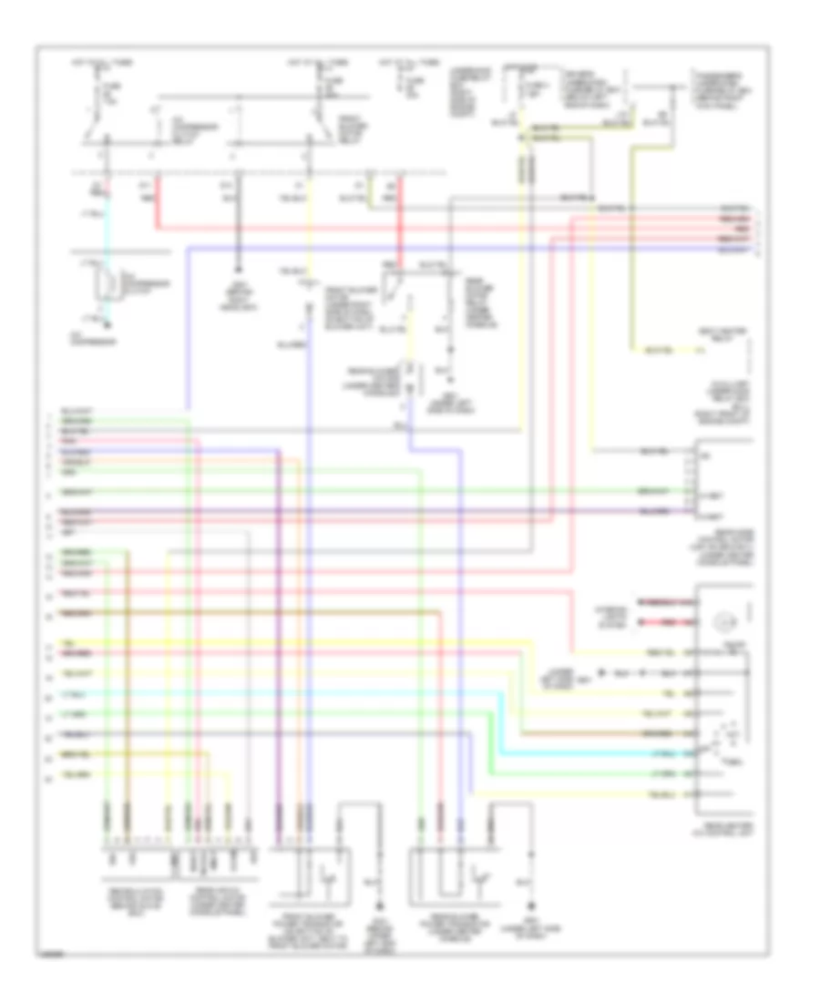
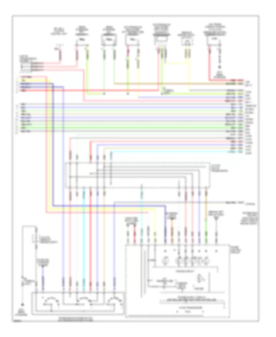
AIR CONDITIONING
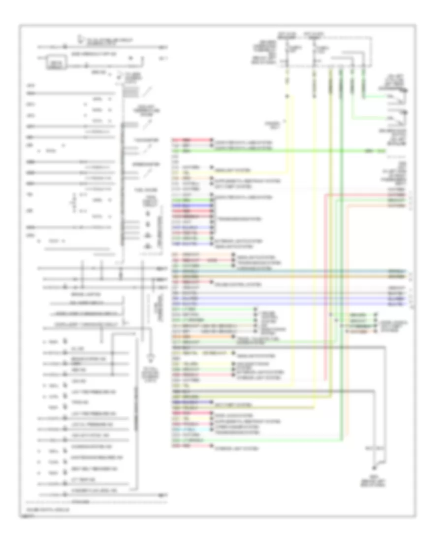
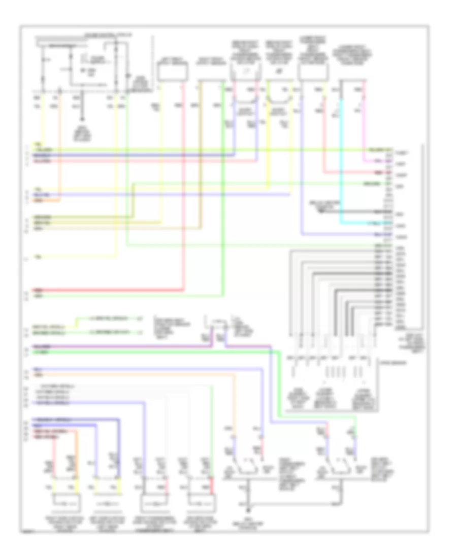
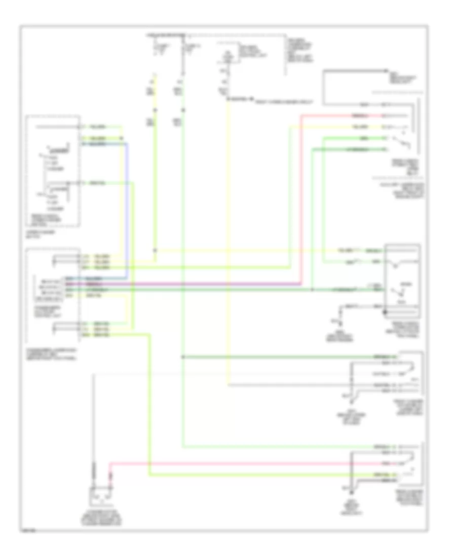
Automatic A/C Wiring Diagram (1 of 3) for Honda Pilot SE 2008
 https://portal-diagnostov.com/license.html
Automotive Electricians Portal FZCO
Automotive Electricians Portal FZCO
https://portal-diagnostov.com/license.html
https://portal-diagnostov.com/license.html
Automotive Electricians Portal FZCO
Automotive Electricians Portal FZCO
List of elements for Automatic A/C Wiring Diagram (1 of 3) for Honda Pilot SE 2008:
- A/c pressure sw
- A10
- A11
- A12
- A13
- A14
- A15
- A16
- A17
- A18
- A19
- A20
- Ac-clk
- Ac-si
- Ac-so
- Air mix cool
- Air mix hot
- Air mix potential
- Amd-p
- B10
- B11
- B12
- B13
- B14
- B15
- B16
- B17
- B18
- B19
- B20
- B21
- B22
- B23
- B24
- B25
- B26
- B27
- B28
- B29
- B30
- Blower feed back
- Blower feedback
- Climate control unit (usa: ex;se & ex-l)
- Defogger system
- Ect sens
- Evap temp sens
- Evaporator temperature sensor (behind glove box)
- Fresh
- Front air mix control motor (on bottom of hvac assembly)
- Front mode control motor (on left end of hvac assembly)
- G401 (behind upper left end of dash)
- Gauge control module
- Gnd
- Ig2
- Illumi (+)
- Illumi (-)
- In-car temp sens
- In-car temperature sensor (lower left center of dash)
- Interior lights system
- M-cool
- M-def
- M-hot
- M-vent
- Mode 1
- Mode 2
- Mode 3
- Mode 4
- Mode def
- Mode vent
- Navigation unit (ex-l; navigation) (under right front seat)
- Out air temp sens
- Outside air temperature sensor (back of front bumper beam)
- Pnk
- Potential +5v
- R. air mix potential
- Rear air mix cool
- Rear air mix hot
- Rear c1
- Rear c2
- Rear c3
- Rear h1
- Rear h2
- Rear h3
- Rear indicator
- Rear mode heat
- Rear mode vent
- Recirculate
- Red
- Relay ctrl
- S-com
- S5v
- Sens comm gnd
- Sunlight sens
- Sunlight sensor (top center of dash)
- Transistor base
- Vss
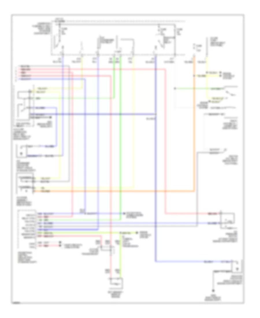
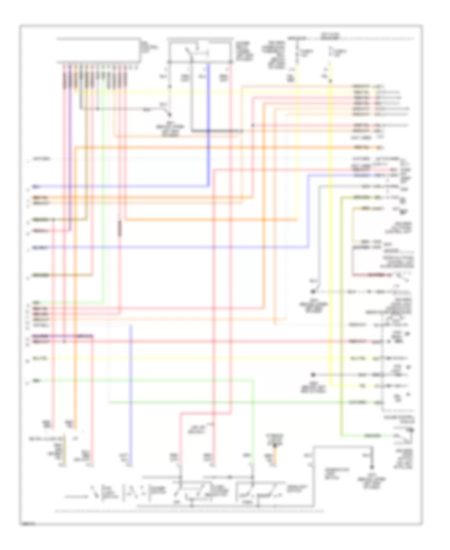
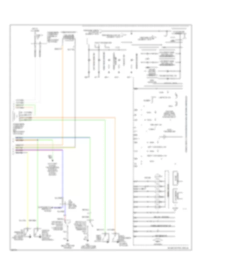
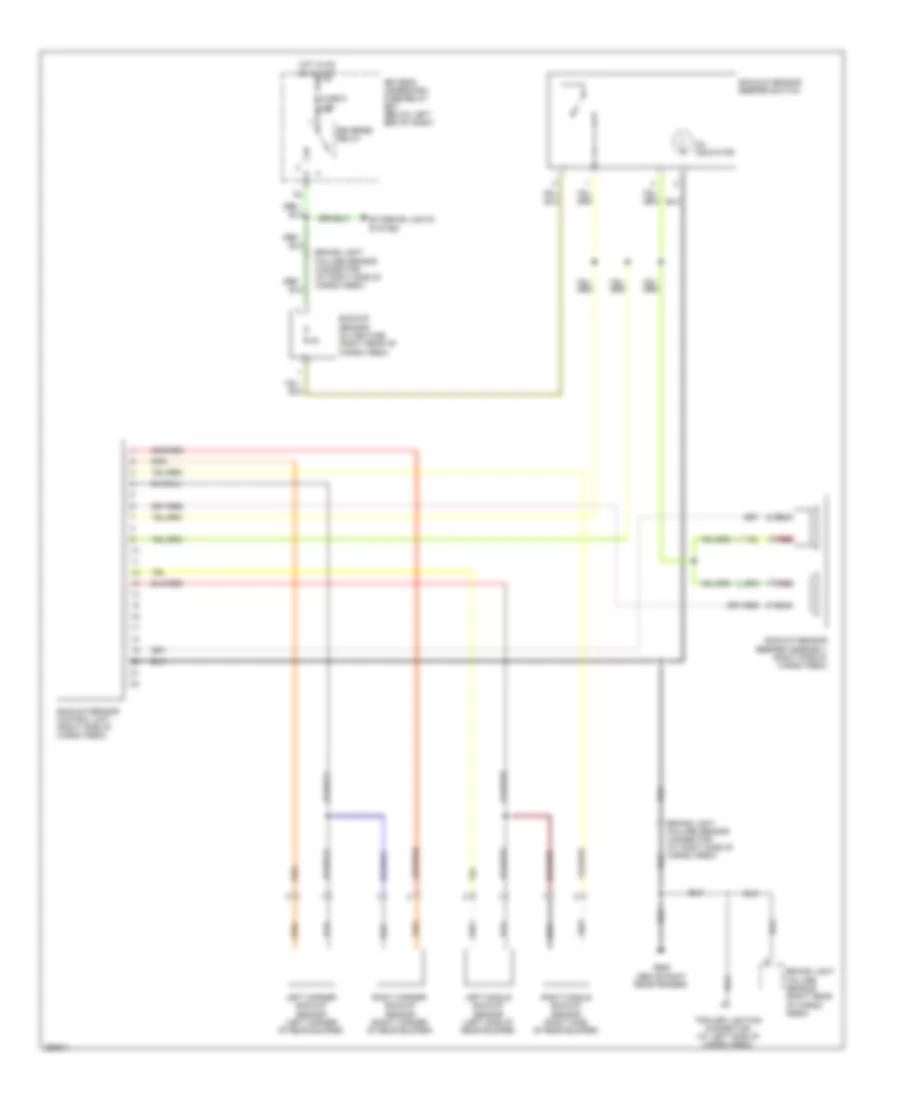
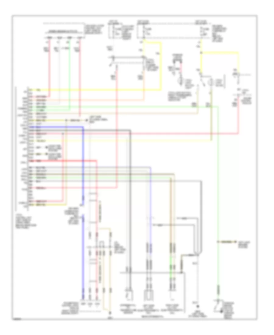
Automatic A/C Wiring Diagram (2 of 3) for Honda Pilot SE 2008
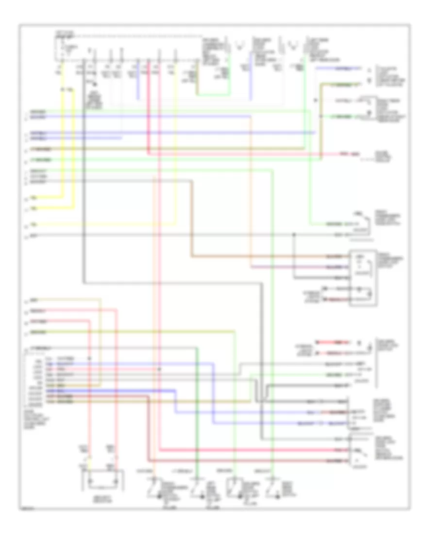
List of elements for Automatic A/C Wiring Diagram (2 of 3) for Honda Pilot SE 2008:
- (under left side of dash)
- A/c compressor
- A/c compressor clutch
- A/c compressor clutch relay
- A10
- Amd-p
- Auxilliary under-hood relay box (ex-l) (right front of engine compt)
- Cool
- D11
- D14
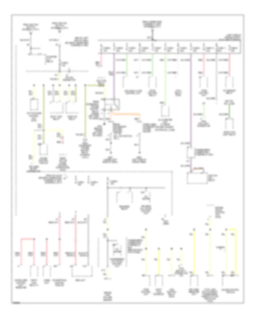
- Driver's under-dash fuse/relay box (below left end of dash)
- Front blower motor (under right side of dash, on bottom of blower unit)
- Front blower motor relay
- Front blower power transistor (on bottom of blower unit, next to front blower motor)
- Frs
- Fuse 3 7.5a
- Fuse 30a
- Fuse 40a
- Fuse 7.5a
- G201 (behind right headlight)
- G401 (behind upper left end of dash)
- G501
- G501 (under left side of dash)
- Hot
- Hot at all times
- Hot in on
- Ig2
- Interior lights system
- J15
- M-cool
- M-heat
- M-hot
- M-vent
- Off
- On ind
- Passenger's under-dash fuse/relay box (behind right kick panel)
- Pnk
- Rear air mix control motor (under center console panel)
- Rear blower motor (under center console)
- Rear blower motor relay (under center console)
- Rear blower power transistor (under center console)
- Rear heater- a/c control unit
- Rear mode control motor (usa: ex;se & ex-l) (under center console panel)
- Rec
- Recirculation control motor (behind glove box)
- Red
- S-com
- S5v
- Seat heater relay
- Underhood fuse/relay box (right side of engine compt)
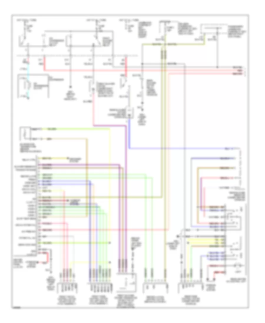
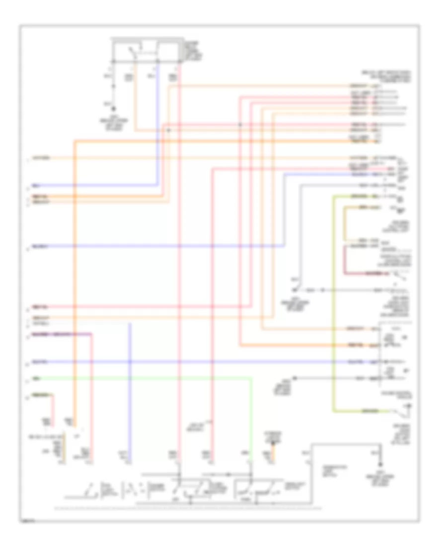
Automatic A/C Wiring Diagram (3 of 3) for Honda Pilot SE 2008
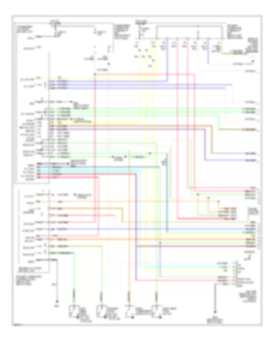
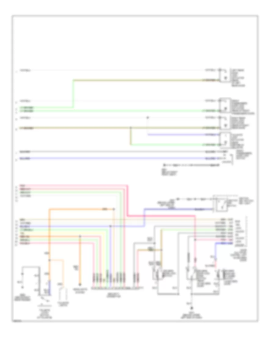
List of elements for Automatic A/C Wiring Diagram (3 of 3) for Honda Pilot SE 2008:
- (at right side of engine compartment)
- A/c condenser fan motor (front middle of engine compt)
- A/c condenser fan relay
- A/c diode a
- A/c diode assembly (behind right side of dash)
- A/c diode b
- A/c on in
- A/c pressure switch
- A14 red
- A17
- Auxiliary under-hood relay box (right front of engine compt)
- Canh
- Canl
- Computer data lines system
- D12
- D15
- D16
- Ect sensor 1 (rear of engine)
- Engine controls system
- Fan control relay
- Fan ctrl
- Fuse 15a
- Fuse 30a
- Fuse 7.5a
- G201 (behind right headlight)
- G202 (right side of engine compt)
- High
- Hot at all times
- Ignition coil relay (behind right kick panel)
- In-line fuse 1 (behind right kick panel)
- J/c c105 (top of transmission)
- Low
- Navigation & wiper/washer systems
- Pgm-f1 main relay 1 (under left side of dash)
- Powertrain control module (pcm) (right side of engine compt)
- Radiator fan motor (front middle of engine compartment)
- Radiator fan relay
- Red
- Red a1
- Relay ctrl
- S1 (thermal joint) (top of transmission)
- Sensor gnd
- Sensor in
- Underhood fuse/relay box (right side of engine compartment)
- Vss out
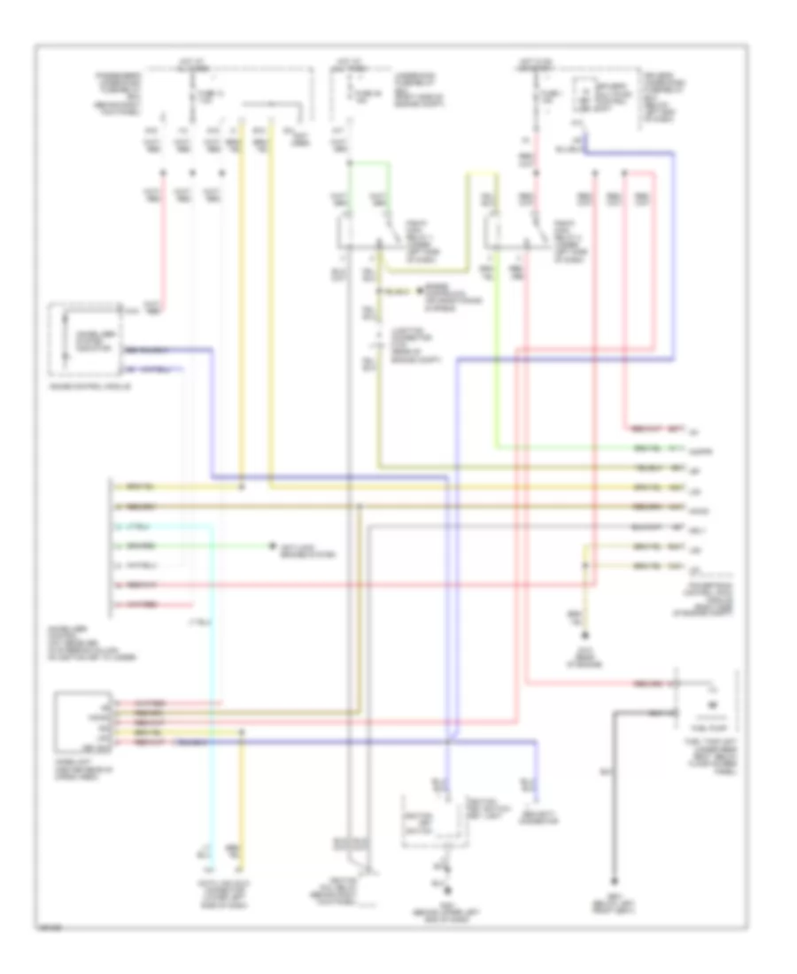
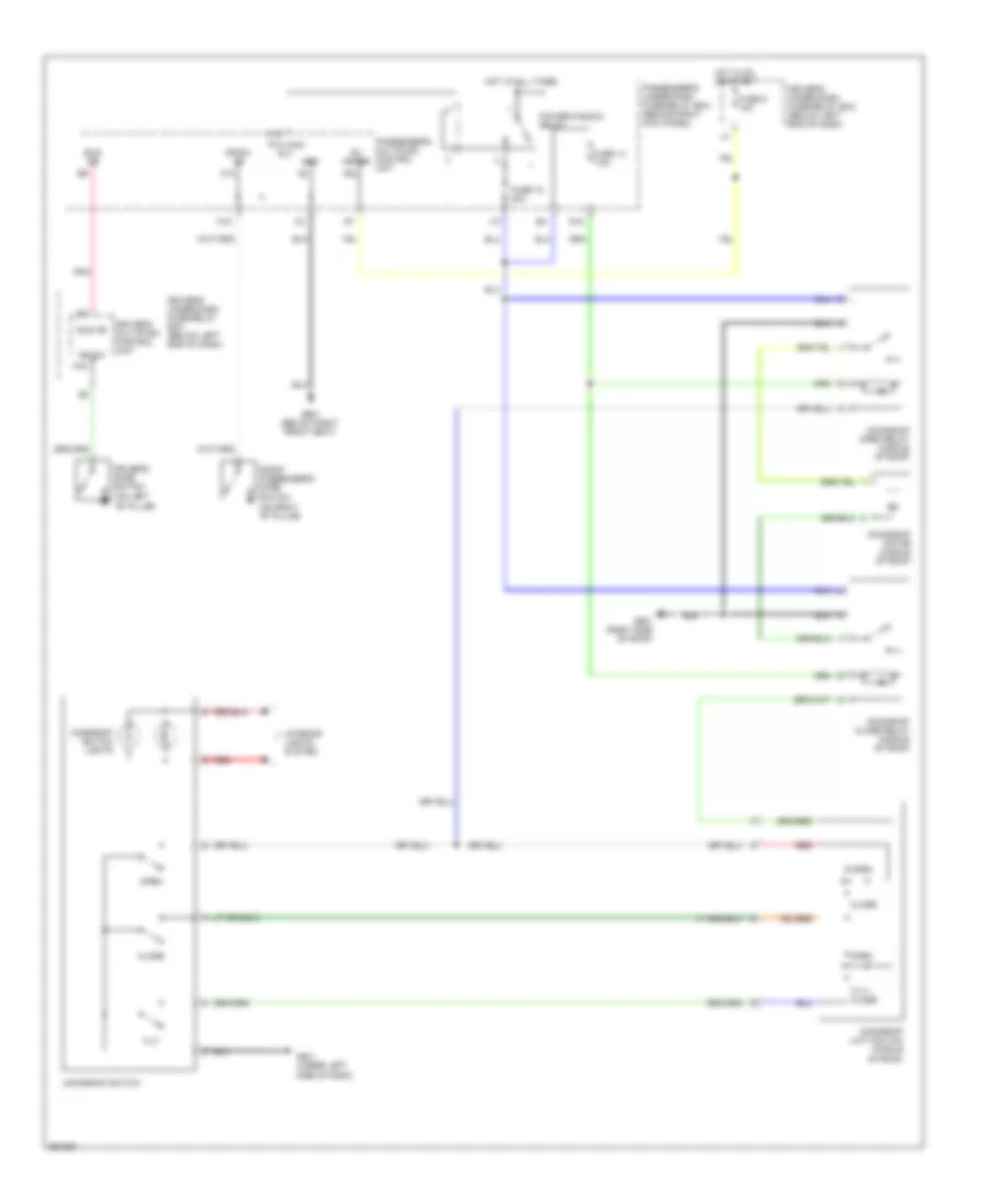
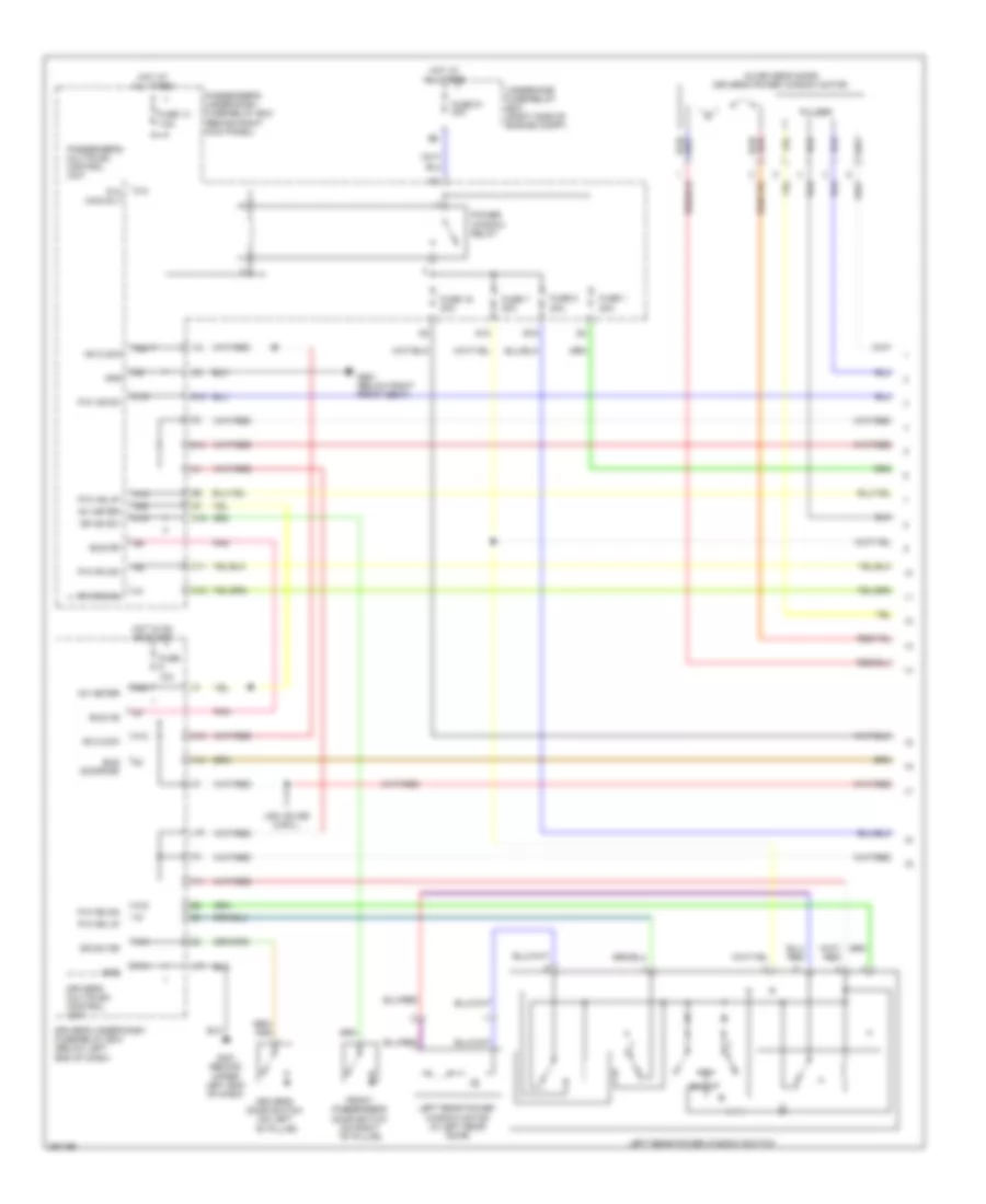
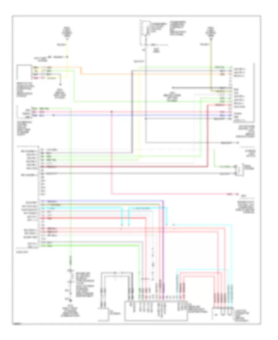
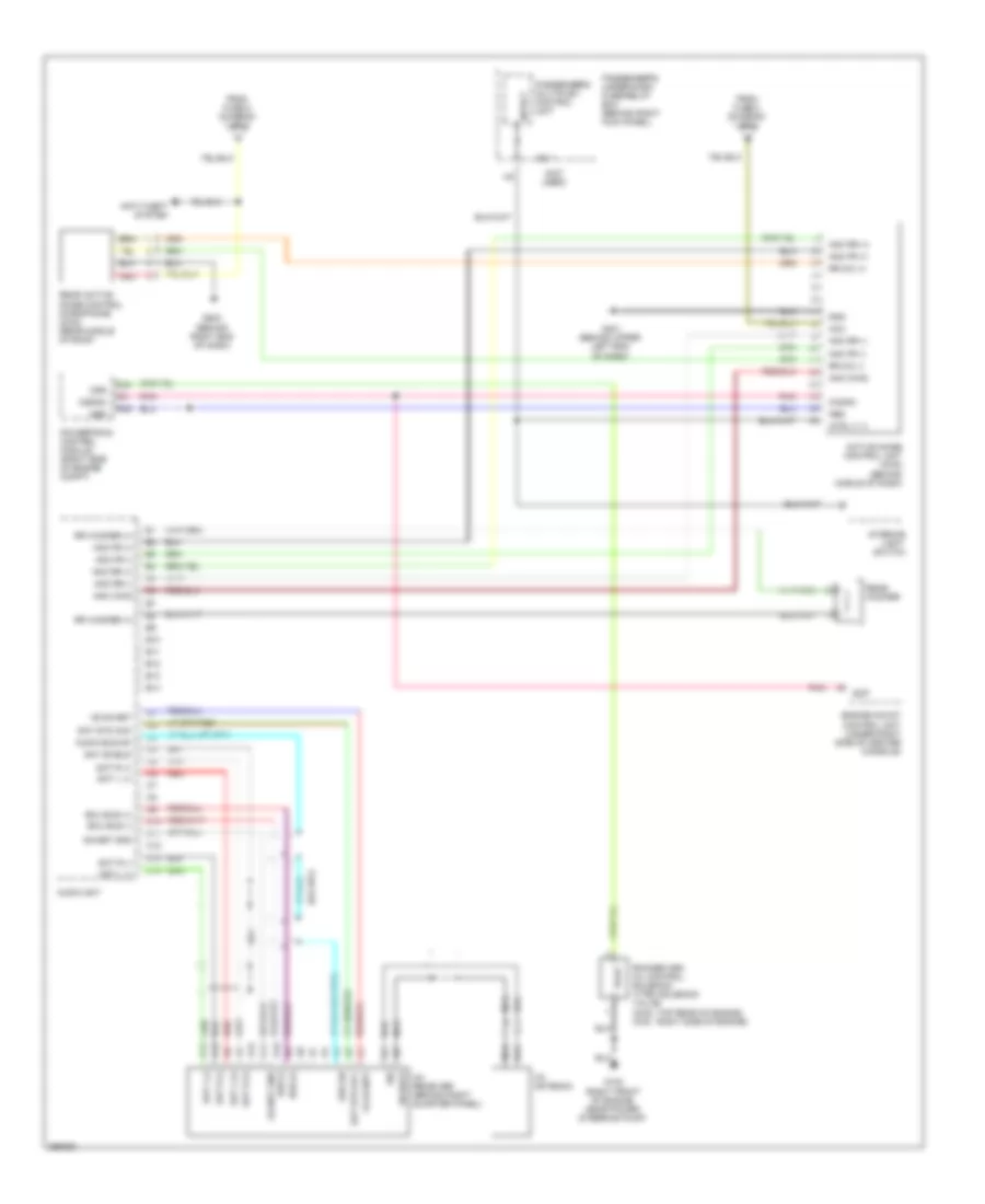
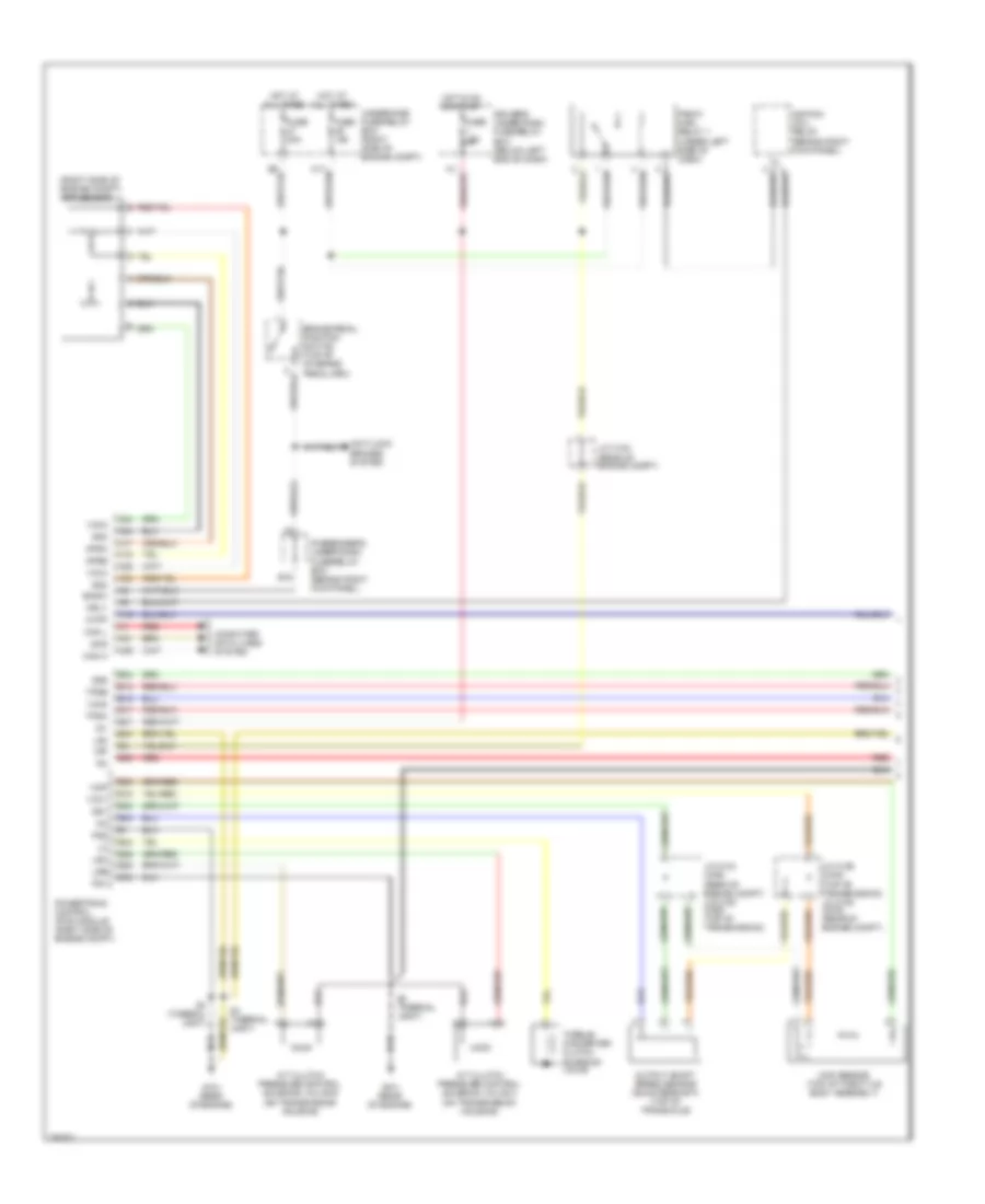
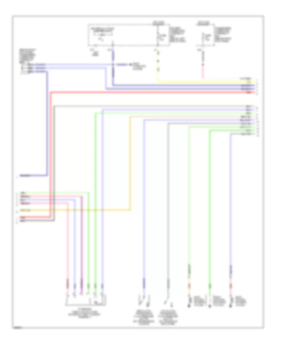
Manual A/C Wiring Diagram (1 of 2) for Honda Pilot SE 2008
List of elements for Manual A/C Wiring Diagram (1 of 2) for Honda Pilot SE 2008:
- (behind upper left end of dash) g401
- (under left side of dash)
- A/c compressor
- A/c compressor clutch
- A/c compressor clutch relay
- A/c pres sw
- A10
- Air mix cool
- Air mix hot
- Air mix potential
- Amd-p
- Blower feedback
- Cool
- D11
- D14
- Defogger system
- Driver's underdash fuse/relay box (below left end of dash)
- Evap temp sens
- Evaporator temperature sensor (behind glove box)
- Fresh
- Front air mix control motor (on bottom of hvac assembly)
- Front blower motor (under right side of dash, on bottom of blower unit)
- Front blower motor relay
- Front blower power transistor (on bottom of blower unit, next to front blower motor)
- Front mode control motor (on left end of hvac assembly)
- Frs
- Fuse 3 7.5a
- Fuse 30a
- Fuse 40a
- Fuse 7.5a
- G201 (behind right headlight)
- G401 (behind upper left end of dash)
- G501
- G501 (under left side of dash)
- Gnd
- Heater control panel (lx & vp)
- Hot
- Hot at all times
- Hot in on
- Ig2
- Illumi (+)
- Illumi (-)
- Interior lights system
- J15
- Light
- M-cool
- M-def
- M-hot
- M-vent
- Mode 1
- Mode 2
- Mode 3
- Mode 4
- Mode def
- Mode vent
- Passenger's underdash fuse/relay box (behind right kick panel)
- Potential +5v
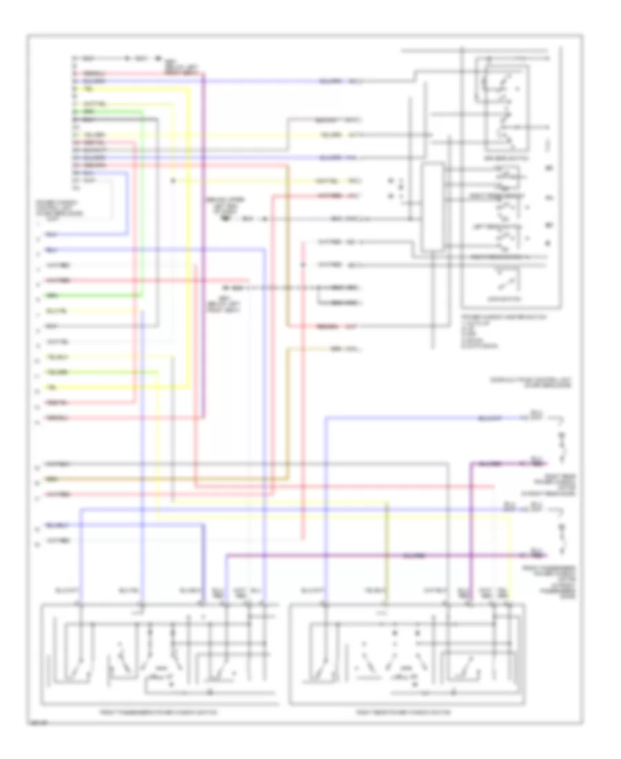
- Rear blower motor (under center console)
- Rear blower motor relay (under center console)
- Rear blower resistor (under center console)
- Rear heater a/c control unit
- Rear mode control motor (under center console)
- Rec
- Recirculate
- Recirculation control motor (behind glove box)
- Red
- Relay ctrl
- S-com
- S5v
- Sens comm gnd
- Transistor base
- Underhood fuse/relay box (right side of engine compt)
- Vent
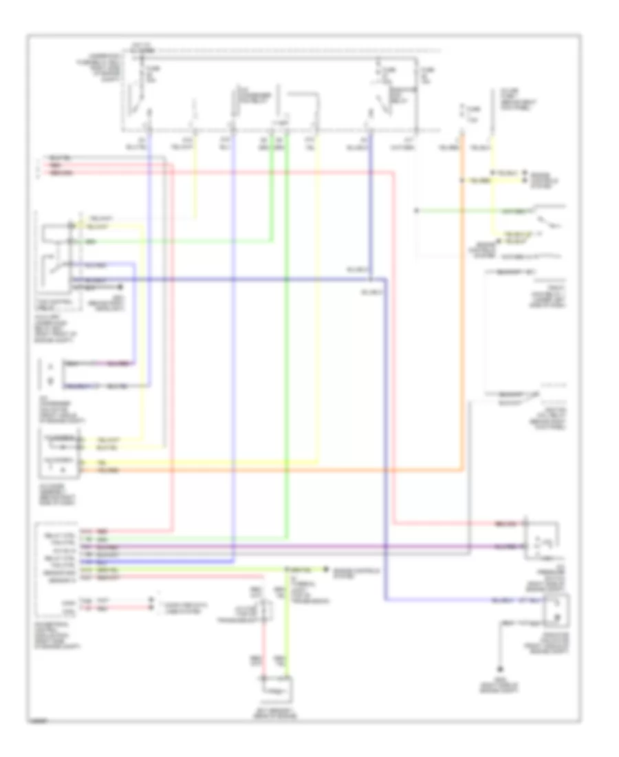
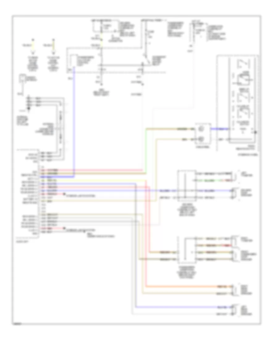
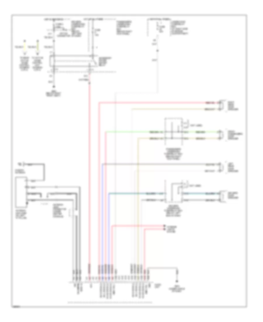
Manual A/C Wiring Diagram (2 of 2) for Honda Pilot SE 2008
List of elements for Manual A/C Wiring Diagram (2 of 2) for Honda Pilot SE 2008:
- A/c condenser fan motor (front middle of engine compt)
- A/c condenser fan relay
- A/c diode a
- A/c diode assembly (behind right side of dash)
- A/c diode b
- A/c on in
- A/c pressure switch (right side of engine compt)
- A14 red
- A17
- Auxiliary under-hood relay box (right front of engine compt)
- Canh
- Canl
- Computer data lines system
- D12
- D15
- D16
- Ect sensor 1 (rear of engine)
- Engine controls system
- Fan control relay
- Fan ctrl
- Fuse 15a
- Fuse 30a
- Fuse 7.5a
- G201 (behind right headlight)
- G202 (right side of engine compt)
- High
- Hot at all times
- Ignition coil relay (behind right kick panel)
- In-line fuse 1 (behind right kick panel)
- J/c c105 (top of transmission)
- Low
- Pgm-f1 main relay 1 (under left side of dash)
- Powertrain control module (pcm) (right side of engine compt)
- Radiator fan motor (front middle of engine compt)
- Radiator fan relay
- Red
- Red a1
- Relay ctrl
- S1 (thermal joint) (top of transmission)
- Sensor gnd
- Sensor in
- Underhood fuse/relay box (right side of engine compt)
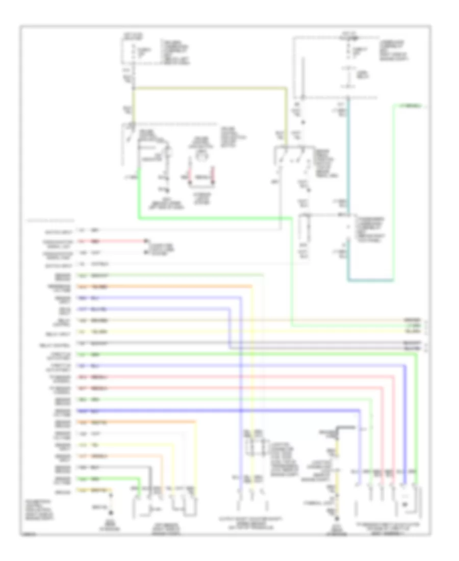
ANTI-LOCK BRAKES
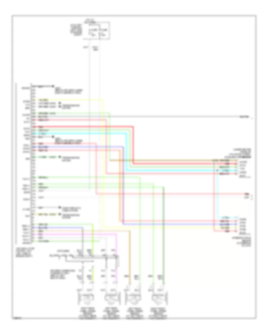
Anti-lock Brakes Wiring Diagram (1 of 2) for Honda Pilot SE 2008
List of elements for Anti-lock Brakes Wiring Diagram (1 of 2) for Honda Pilot SE 2008:
- (4wd)
- (left side of engine compt)
- (not used)
- (under center console) yaw rate-lateral acceleration sensor
- +b-fsr
- +b-mr
- Auxiliary fuse box (left side of engine compt)
- Can-h
- Can-l
- Computer data lines system
- Driver's under-dash fuse/relay box (below left end of dash)
- F13
- F14
- Flp
- Fls (+)
- Fls (-)
- Frp
- Frs (+)
- Frs (-)
- Fuse 30a
- Fuse 40a
- G302 (below driver's under- dash fuse/relay box)
- Glat
- Glong
- Gnd
- Hot at all times
- Ig1
- J17
- K-line
- Left front wheel speed sensor (at left front hub assembly)
- Left rear wheel speed sensor (at left rear hub assembly)
- M10
- Mr-gnd
- Red
- Right front wheel speed sensor (at right front hub assembly)
- Right rear wheel speed sensor (at right rear hub assembly)
- Rlp
- Rls (+)
- Rls (-)
- Rrp
- Rrs (+)
- Rrs (-)
- S-gnd
- Sgnd
- Steering angle sensor (in steering column)
- Str-a
- Str-b
- Str-d
- Stra
- Strb
- Strz
- Svcc
- Transmissions system
- Vsa modulator control unit
- Yaw
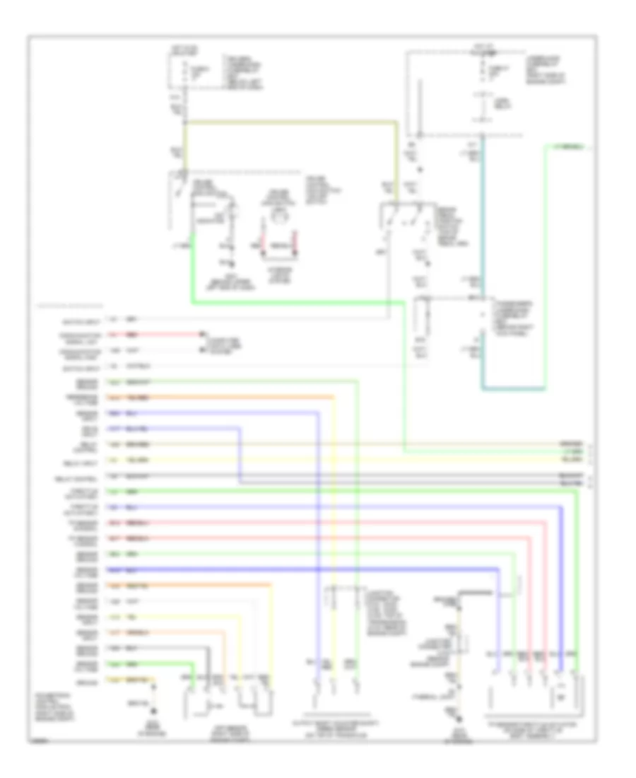
Anti-lock Brakes Wiring Diagram (2 of 2) for Honda Pilot SE 2008
List of elements for Anti-lock Brakes Wiring Diagram (2 of 2) for Honda Pilot SE 2008:
- A11
- A36
- Abs indicator
- B15
- Bkswnc
- Brake fluid level switch (integral to brake fluid reservoir cap)
- Brake pedal position switch (top of brake pedal arm)
- Brake system indicator (usa)
- Canada
- Canh
- Canl
- Compulsory turn on circuit
- Cruise control main switch/ vsa off switch
- D13
- Driver's multiplex control unit
- Driver's under-dash fuse/relay box (below left end of dash)
- Drl control unit
- F-can trans
- Fail safe circuit
- Fuse 10a
- Fuse 15a
- G301 (left front side of engine compt)
- G501 (under left side of dash)
- Gauge control module
- Hot in on or start
- Immobilizer control unit receiver (in steering column, on ignition key cylinder)
- J/c c306 (behind left side of dash)
- M14
- P/ brk sw
- Parking brake switch (top of parking brake pedal)
- Powertrain control module (pcm) (right side of engine compt)
- Red
- Usa
- Vsa activation indicator
- Vsa indicator
- Vtm-4 control unit (4wd) (left side of cargo area, behind rear side trim panel)
- Warning drive circuit
ANTI-THEFT
Forced Entry Wiring Diagram, EX, EX-L, SE (1 of 2) for Honda Pilot SE 2008
List of elements for Forced Entry Wiring Diagram, EX, EX-L, SE (1 of 2) for Honda Pilot SE 2008:
- (below right front seat) g651
- (not used)
- +b clock
- +b d/l
- A10
- A11
- A12
- A13
- A14
- A15
- A16
- A17
- A21
- A22
- A23
- A24
- Antenna
- B11
- B14
- B21
- B22
- Bus (door/dr)
- Bus as
- Bus dr
- C14
- C16
- C20
- D/l lock
- D/l unlck dr
- D/l unlock
- Door lock
- Door unlock
- Dr sw as
- Dr sw dr
- Dr sw ra
- Dr sw rd
- Driver's multiplex control unit
- Driver's under-dash fuse/relay box (below left end of dash)
- E10
- E15
- E17
- Front passenger's door lock actuator (rear of front passenger's door)
- Fuse 12 20a
- Fuse 13 7.5a
- G15
- G201 (behind right headlight)
- G401 (behind upper left end of dash)
- G501
- G503 (behind right end of dash)
- G601 (below left front seat)
- G651 (below right front seat)
- G652 (above right rear fender)
- Gnd
- H/l rly+
- H14
- Headlights system
- Hood sw
- Horn rly
- Horns system
- Hot at all times
- I12
- I14
- Ig key sw
- Ig1
- Ig1 meter
- Ignition key switch
- Ignition key switch/ key light
- Instrument cluster system
- Interior lights system
- Intrlt
- K/c as lock
- K/c as unlock
- K/l lock
- K/l panic
- K/l unlock
- Keyless receiver unit (behind right side of glove box)
- Left rear door lock knob switch (rear of left rear door)
- M19
- Nca
- Panic
- Passenger's multiplex control unit
- Passenger's under-dash fuse/relay box (behind right kick panel)
- Pnk
- Radio sw
- Rem as lock
- Rem as unlock
- Right rear door lock knob switch
- Scty in
- Security hood switch (center front of engine compt)
- Sgnd
- Sil as unlock
- Sil ra unlock
- Sil rd unlock
- Sound systems
- T/g sw
- Tailgate latch switch (in tailgate)
- Tailgate lights
Forced Entry Wiring Diagram, EX, EX-L, SE (2 of 2) for Honda Pilot SE 2008
List of elements for Forced Entry Wiring Diagram, EX, EX-L, SE (2 of 2) for Honda Pilot SE 2008:
- A12
- A15
- A16
- A17
- A18
- B30
- Door multiplex control unit (in driver's door)
- Driver's door key cylinder switch (in driver's door)
- Driver's door lock actuator (rear of driver's door)
- Driver's door lock knob switch (rear of driver's door)
- Driver's door lock switch
- Driver's door switch (on left ``b" pillar)
- Driver's underdash fuse/relay box (below left end of dash)
- Front passenger's door lock knob switch
- Front passenger's door lock switch
- Front passenger's door switch (on right ``b" pillar)
- Fuse 9 10a
- G401 (behind upper left end of dash)
- Gauge control module
- H16
- Hot in on or start
- Interior lights system
- K13
- L13
- Left rear door lock actuator (rear of left rear door)
- Left rear door switch (on left ``c" pillar)
- Lock
- Mpx-dr
- Pnk
- Red
- Right rear door lock actuator (rear of right rear door)
- Right rear door switch
- Security indicator
- Tailgate lock actuator (near center of tailgate)
- Unlock
- Vbu
Forced Entry Wiring Diagram, VP for Honda Pilot SE 2008
List of elements for Forced Entry Wiring Diagram, VP for Honda Pilot SE 2008:
- +b clock
- +b d/l
- A11
- A13
- A14
- A15
- A16
- A17
- A23
- A24
- B14
- B16
- B17
- B27
- B28
- B34
- B35
- C14
- C16
- Dr lk
- Dr sw as
- Dr sw dr
- Dr sw ra
- Dr sw rd
- Dr unlk
- Driver's door switch (on left ``b" pillar)
- Driver's multiplex control unit
- Driver's under-dash fuse/relay box (below left end of dash)
- Driver's underdash fuse/relay box (below left end of dash)
- E10
- Exterior lights system
- Front passenger's door switch
- Fuse 12 20a
- Fuse 13 7.5a
- Fuse 9 10a
- G401 (behind upper left end of dash)
- G652 (above right rear fender)
- Gauge control module
- H16
- Headlights system
- Horn relay
- Horn rly
- Horns system
- Hot at all times
- Hot in on or start
- I12
- Ig key sw
- Ignition key switch
- Ignition key switch/ key light
- Interior lights system
- J14
- J15
- K/l lock
- K/l unlock
- Keyless receiver unit (behind right side of glove box)
- Left rear door switch (on left "c" pillar)
- Microphone
- Microphone jack
- Nca
- Passenger's multiplex control unit
- Passenger's under-dash fuse/relay box (behind right kick panel)
- Right rear door switch
- Security connector
- Security control unit
- Security diode 1
- Security diode 2
- Security led
- T/g sw
- Tailgate latch switch (in tailgate)
- Underhood fuse/relay box (right side of engine compt)
Immobilizer Wiring Diagram for Honda Pilot SE 2008
List of elements for Immobilizer Wiring Diagram for Honda Pilot SE 2008:
- A11
- A13
- A17
- A1o
- A22
- A44
- Anti-lock brakes system
- B18
- B28
- B37
- B43
- C40
- Data link (dlc) connector (lower left side of dash)
- Driver's multiplex control unit
- Driver's under-dash fuse/relay box (below left end of dash)
- Engine controls & air conditioning systems
- Fuel pump
- Fuel tank unit (under rear seat, below floor access panel)
- Fuse 1 15a
- Fuse 13 7.5a
- Fuse 46 15a
- G101 (rear of engine)
- G14 (not used)
- G15
- G16
- G401 (behind upper left end of dash)
- G601 (below left front seat)
- Gauge control module
- Hot at all times
- Hot in on or start
- I12
- Ig1
- Ig2
- Ignition coil relay (behind right kick panel)
- Ignition key switch
- Ignition key switch/ key light
- Igp
- Immobilizer control unit receiver (in steering column, on ignition key cylinder)
- Immobilizer system indicator
- Imocd
- Imoes unit (center rear of cargo area)
- Imofpr
- Junction connector c103 (rear of engine compt)
- Key sw
- Lg1
- Lg2
- Lg3
- Mrly
- Passenger's under-dash fuse/relay box (behind right kick panel)
- Pgm-fi main relay 1 (under left side of dash)
- Pgm-fi main relay 2 (under left side of dash)
- Powertrain control (pcm) module (right side of engine compt)
- Security connector
- Underhood fuse/relay box (right side of engine compt)
BODY CONTROL MODULES
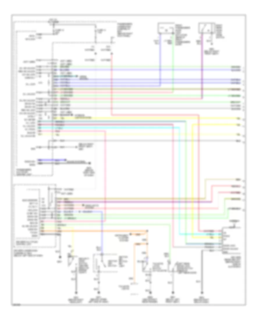
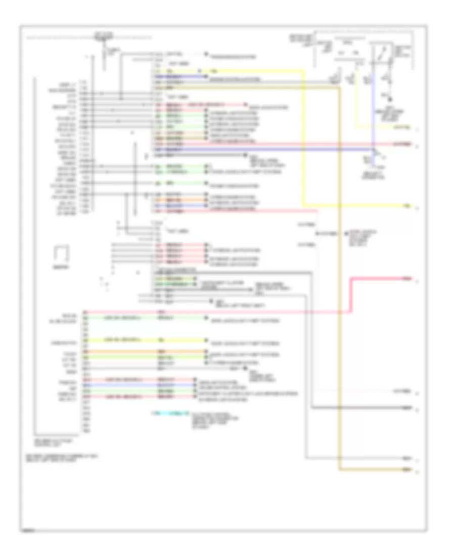
Body Control Modules Wiring Diagram (1 of 2) for Honda Pilot SE 2008
List of elements for Body Control Modules Wiring Diagram (1 of 2) for Honda Pilot SE 2008:
- (behind upper left end of dash) g401
- (not used)
- (usa: ex, se & ex-l)
- +b clock
- A10
- A11
- A12
- A13
- A14
- A15
- A16
- A17
- A18
- A19
- A20
- A21
- A22
- A23
- A24
- At-p
- At-s
- B10
- B11
- B12
- B13
- B14
- B15
- B16
- B17
- B18
- B19
- B20
- B21
- B22
- Beeper
- Bus (door/dr)
- Bus as
- C324
- Check
- Cruise control system
- D12
- D15
- D17
- D18
- D19
- D2o
- Door locks & anti-theft systems
- Door locks & anti-theft systems (ex, ex-l)
- Door locks system
- Dr sw dr
- Dr sw rd
- Driver's multiplex control unit
- Driver's underdash fuse/relay box (below left end of dash)
- E10
- Engine controls system
- Exterior lights system
- F10
- Fr int sw
- Fr wash sw
- Fr wip as
- Fr wip rly
- Fuse 9 10a
- G401 (behind upper left end of dash)
- G401 (behind upper left end of dash)
- G501 (under left side of dash)
- G601 (below left front seat)
- Ground
- H/l rly+
- H14
- H16
- Headlights system
- Hood switch
- Hot in on or start
- Ig1 meter
- Igkey lt
- Igkey sw
- Ignition key light
- Ignition key switch
- Ignition key switch/key light
- Ill+
- Instrument cluster & anti-lock brakes systems
- Instrument cluster system
- Int vr+
- Int vr-
- Interior lights system
- J13
- J14
- J15
- K10
- K16
- L15
- L18
- M12
- M19
- M20
- Multiplex control inspection connector (behind left side of dash)
- P/brk sw
- P/w rd down
- P/w rd up
- Pass sw
- Pnk
- Power windows system
- Security connector
- Security in
- Sgnd
- Sil rd unlock
- Sml rly+
- Sml rly-
- Stop sw
- T option connector
- T/g sw
- Transmissions system
- Vsp
- Wiper/washer system
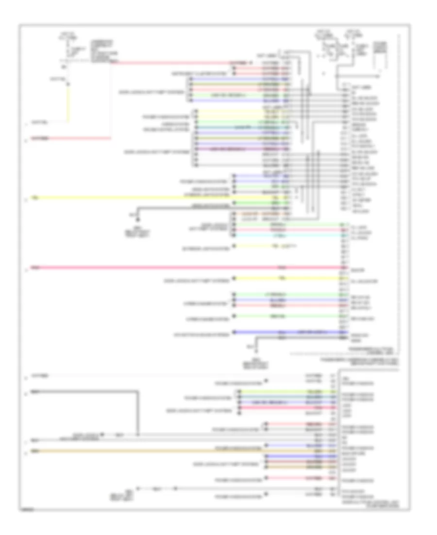
Body Control Modules Wiring Diagram (2 of 2) for Honda Pilot SE 2008
List of elements for Body Control Modules Wiring Diagram (2 of 2) for Honda Pilot SE 2008:
- (lx & vp)
- (not used)
- (usa: ex, & ex-l)
- (usa: ex, se & ex-l)
- +b clock
- +b d/l
- A10
- A11
- A12
- A13
- A14
- A15
- A16
- A17
- A18
- A19
- A20
- A21
- A22
- A23
- A24
- B10
- B11
- B12
- B13
- B14
- B15
- B16
- B17
- B18
- B19
- B20
- B21
- B22
- Bus (mpx-dr)
- Bus dr
- C11
- C12
- C13
- C14
- C16
- C20
- Cruise control system
- D/l lock
- D/l unlock
- D/l unlock dr
- Door locks & anti-theft systems
- Door multiplex control unit (in driver's door)
- Dr sw as
- Dr sw ra
- E15
- E17
- E18
- Exterior lights system
- Fuse 20a
- Fuse 47 20a
- Fuse 5 (not used)
- Fuse 7.5a
- G15
- G16
- G503 (behind right end of dash)
- G601 (below left front seat)
- G651 (below right front seat)
- Ground
- H/l rly-
- H16
- Headlights system
- Horn rly
- Horns system
- Hot at all times
- I12
- I14
- Ig1 meter
- Instrument cluster system
- Interior lights system
- Intrlt
- K/c as lock
- K/c as unlock
- K/l lock
- K/l panic
- K/l unlock
- Lock
- Navigation & sound systems
- P/w as down
- P/w as up
- P/w main rly
- P/w main sw
- P/w ra down
- Passenger's multiplex control unit
- Passenger's underdash fuse/relay box (behind right kick panel)
- Pnk
- Power window relay
- Power windows
- Power windows system
- Radio sw
- Rem as lock
- Rem as unlock
- Rr int sw
- Rr wash sw
- Rr wip as
- Rr wip rly
- Sgnd
- Sil as unlock
- Sil ra unlock
- Underhood fuse/relay box (at right side of engine compartment)
- Unlock
- Vbu
- Wiper/washer system
COMPUTER DATA LINES
Computer Data Lines Wiring Diagram for Honda Pilot SE 2008
List of elements for Computer Data Lines Wiring Diagram for Honda Pilot SE 2008:
- (at right side of engine compt)
- (behind left side of dash) junction connector c306
- (not used)
- (under left side of dash)
- (under right side of center console) engine mount control unit
- (w/ 4wd)
- 2wd red
- 4wd
- A11
- A15
- A17
- A18
- A20
- A22
- A24
- A31
- A36
- A42
- A43
- B10
- B18
- B19
- Chk
- Data link connector (dlc) (lower left side of dash)
- Diag +
- Diag -
- Diag-h
- Driver's multiplex control unit
- Driver's underdash fuse/relay box (below left end of dash)
- F-can hi
- F-can lo
- Fuse 15a
- G14
- G401 (behind upper left end of dash)
- G501 (under left side of dash)
- Gauge control module
- Hot at all times
- Immobilizer control unit receiver (in steering column, on ignition key cylinder)
- K-line
- K14
- Lg3
- Mes connector
- Multiplex control inspection connector (behind left side of dash)
- Navigation service check connector (under right front seat)
- Navigation unit (under right front seat)
- Passenger's underdash fuse/relay box (behind right kick panel)
- Powertrain control (pcm) module) (right side of engine compt)
- Red
- Scs
- Srs unit (behind lower center of dash)
- Tpms receiver unit (under left side of dash)
- Underhood fuse/relay box
- Vsa modulator control unit (left side of engine compt)
- Vtm-4 control unit (at left side of cargo area, behind rear side trim panel)
- Wen
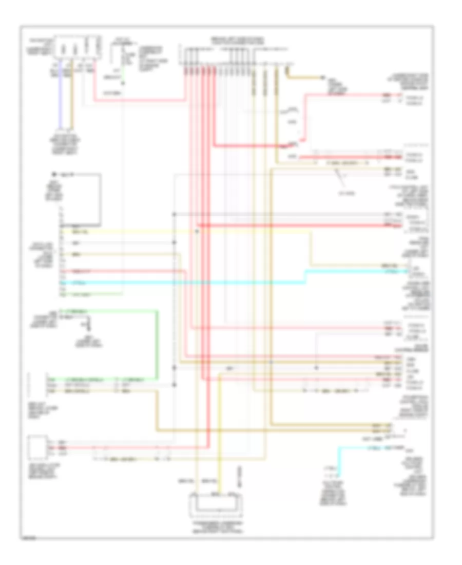
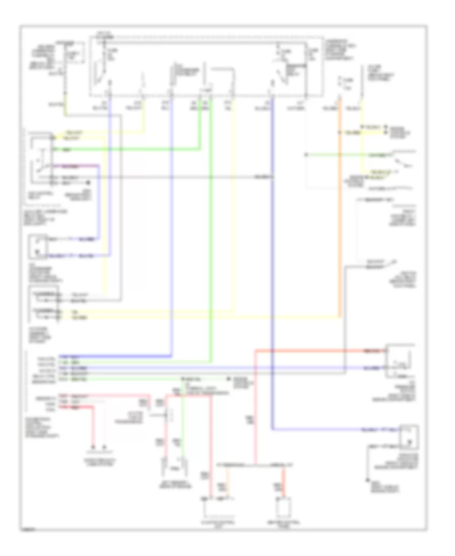
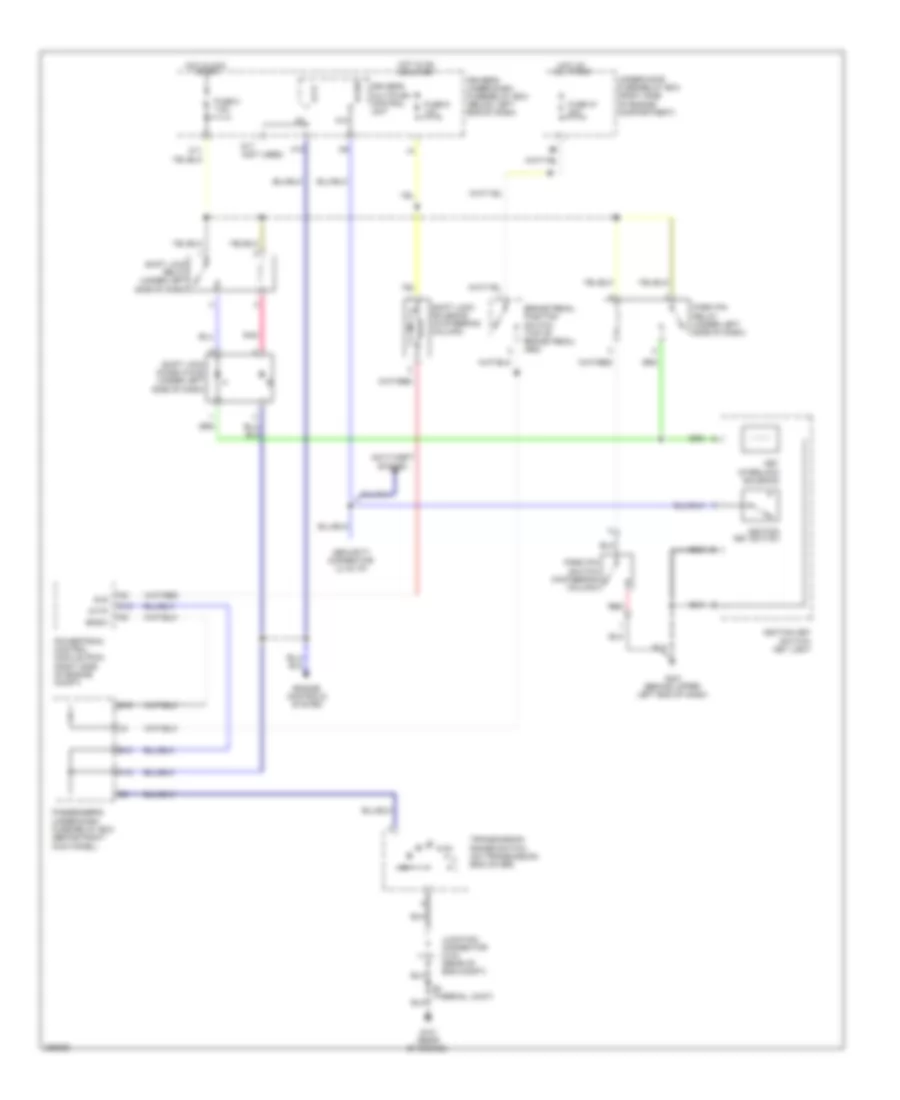
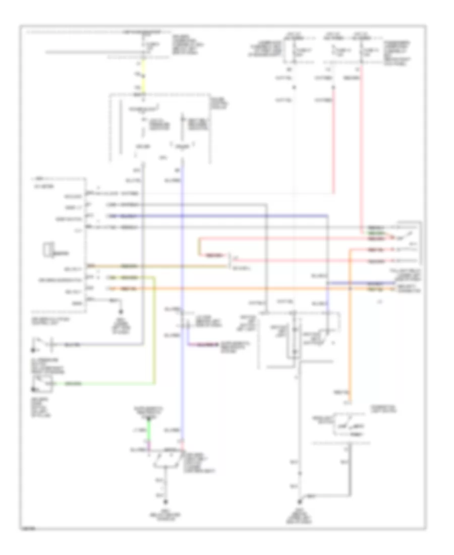
COOLING FAN
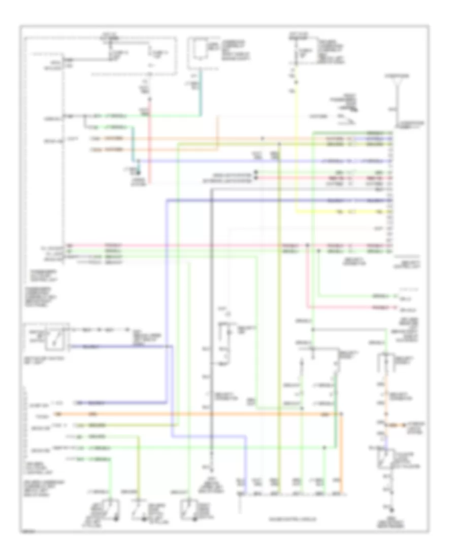
Cooling Fan Wiring Diagram for Honda Pilot SE 2008
List of elements for Cooling Fan Wiring Diagram for Honda Pilot SE 2008:
- (top of transmission)
- A/c condenser fan motor (front middle of engine compt)
- A/c condenser fan relay
- A/c diode a
- A/c diode assembly (right side of dash)
- A/c diode b
- A/c on in
- A/c pressure switch (right side of engine compartment)
- A1 red
- A17
- Automatic a/c
- Auxiliary under-hood relay box (right front of eng compt)
- B22
- B27
- Canh
- Canl
- Climate control unit
- Computer data lines system
- D12
- D15
- D16
- Ect sensor 1 (rear of engine)
- Engine controls system
- Fan control relay
- Fan ctrl
- Fuse 15a
- Fuse 3 7.5a
- Fuse 30a
- Fuse 7.5a
- G201 (behind right headlight)
- G202 (right side of engine compt)
- Heater control panel
- High
- Hot at all times
- Hot in on driver's underdash fuse/relay box (below left end of dash)
- Ignition coil relay (behind right kick panel)
- In-line fuse 1 (behind right kick panel)
- J/c c105 (top of transmission)
- Low
- Manual a/c
- Pgm-f1 main relay 1 (under left side of dash)
- Powertrain control module (pcm) (right side of engine compt)
- Radiator fan motor (front middle of engine compartment)
- Radiator radiator fan relay
- Relay ctrl
- Sensor gnd
- Sensor in
- Underhood fuse/relay box (right side of engine compartment)
CRUISE CONTROL
Cruise Control Wiring Diagram, with Navigation (1 of 2) for Honda Pilot SE 2008
List of elements for Cruise Control Wiring Diagram, with Navigation (1 of 2) for Honda Pilot SE 2008:
- "on" indicator
- (2wd) (4wd)
- A11
- A17
- A18
- A20
- A24
- A25
- A34
- A35
- A36
- App sensor (right side of engine compt)
- B12
- B14
- B16
- B17
- B18
- B19
- B33
- B34
- B40
- Braided wire
- Brake pedal position switch (top of brake pedal arm)
- C17
- C40
- Communication
- Computer data lines system
- Cruise control main switch
- Cruise control main switch light
- Cruise control main switch/ vsa off switch
- Drive input
- Driver's under-dash fuse/relay box (below left end of dash)
- Fuse 47 20a
- Fuse 6 15a
- G101 (rear of engine)
- G401 (behind upper left end of dash)
- Ground
- Horn relay
- Hot at all times
- Hot in on or start
- Interior lights system
- Junction connector c104 (rear of engine compt)
- Junction connector c104 c105 (c105: top of transmission, (c104: rear of engine compt)
- M14
- Output shaft (counter shaft) speed sensor (on top of transaxle)
- Passenger's under-dash fuse/relay box (behind right kick panel)
- Powertrain control module (pcm) (right side of engine compt)
- Red
- Reference voltage
- Relay control
- Relay input
- S4 (thermal joint)
- Sensor ground
- Sensor input
- Sensor voltage
- Signal high
- Signal low
- Switch input
- Throttle actuator(+)
- Throttle actuator(-)
- Tp sensor a signal
- Tp sensor b signal
- Tp sensor/throttle actuator (on side of throttle body assembly)
- Under-hood fuse/relay box right side of engine compt)
Cruise Control Wiring Diagram, with Navigation (2 of 2) for Honda Pilot SE 2008
List of elements for Cruise Control Wiring Diagram, with Navigation (2 of 2) for Honda Pilot SE 2008:
- A11
- A17
- Auxiliary fuse box (left side of engine compt)
- B11
- B12
- B13
- B25
- Cable reel (inside steering wheel)
- Cancel switch
- Computer data lines system
- Cruise control dimming circuit
- Cruise control indicator
- Cruise control set/ resume/ cancel switch
- Driver's under-dash fuse/relay box (below left end of dash)
- Engine controls
- Etcs control relay (behind right kick panel)
- F-can transceiver
- Fuse 46 15a
- Fuse 7 15a
- Fuse 9 10a
- G101 (rear of engine)
- Gauge control module
- Horn switch
- Hot at all times
- Hot in on or start
- Ignition coil relay (behind right kick panel)
- Junction connector c104 (rear of engine compt)
- Pgm-fi main relay 1 (under left side of dash)
- Red
- Resume switch
- Set switch
- Steering wheel
- System
- Transmission range switch (on transmission end cover)
- Under hood fuse/relay box (right side of engine compt)
Cruise Control Wiring Diagram, without Navigation (1 of 2) for Honda Pilot SE 2008
List of elements for Cruise Control Wiring Diagram, without Navigation (1 of 2) for Honda Pilot SE 2008:
- "on" indicator
- (2wd) (4wd)
- A11
- A17
- A18
- A20
- A24
- A25
- A34
- A35
- A36
- App sensor (right side of engine compt)
- B12
- B14
- B16
- B17
- B18
- B19
- B33
- B34
- B40
- Braided wire
- Brake pedal position switch (top of brake pedal arm)
- C17
- C40
- Communication
- Computer data lines system
- Cruise control main switch
- Cruise control main switch light
- Cruise control main switch/ vsa off switch
- Drive input
- Driver's under-dash fuse/relay box (below left end of dash)
- Fuse 47 20a
- Fuse 6 15a
- G101 (rear of engine)
- G401 (behind upper left end of dash)
- Ground
- Horn relay
- Hot at all times
- Hot in on or start
- Interior lights system
- Junction connector c104 (rear of engine compt)
- Junction connector c104 c105 (c105: top of transmission, (c104: rear of engine compt)
- M14
- Output shaft (counter shaft) speed sensor (on top of transaxle)
- Passenger's under-dash fuse/relay box (behind right kick panel)
- Powertrain control module (pcm) (right side of engine compt)
- Red
- Reference voltage
- Relay control
- Relay input
- S4 (thermal joint)
- Sensor ground
- Sensor input
- Sensor voltage
- Signal high
- Signal low
- Switch input
- Throttle actuator(+)
- Throttle actuator(-)
- Tp sensor a signal
- Tp sensor b signal
- Tp sensor/throttle actuator (on side of throttle body assembly)
- Under-hood fuse/relay box (right side of engine compt)
Cruise Control Wiring Diagram, without Navigation (2 of 2) for Honda Pilot SE 2008
List of elements for Cruise Control Wiring Diagram, without Navigation (2 of 2) for Honda Pilot SE 2008:
- A11
- A17
- Auxiliary fuse box (left side of engine compt)
- B11
- B12
- B13
- B25
- Cable reel (inside steering wheel)
- Cancel switch
- Computer data lines system
- Cruise control dimming circuit
- Cruise control indicator
- Cruise control set/ resume/ cancel switch
- Driver's under-dash fuse/relay box (below left end of dash)
- Engine controls
- Etcs control relay (behind right kick panel)
- F-can transceiver
- Fuse 46 15a
- Fuse 7 15a
- Fuse 9 10a
- G101 (rear of engine)
- Gauge control module
- Horn switch
- Hot at all times
- Hot in on or start
- Ignition coil relay (behind right kick panel)
- Junction connector c104 (rear of engine compt)
- Lx, vp
- Pgm-fi main relay 1 (under left side of dash)
- Red
- Resume switch
- S2 (thermal joint)
- Security connector
- Set switch
- Steering wheel
- System
- Transmission range switch (on transmission end cover)
- Under hood fuse/relay box (right side of engine compt)
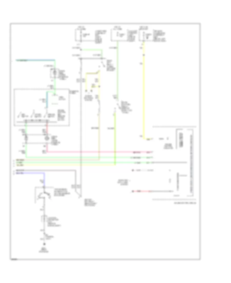
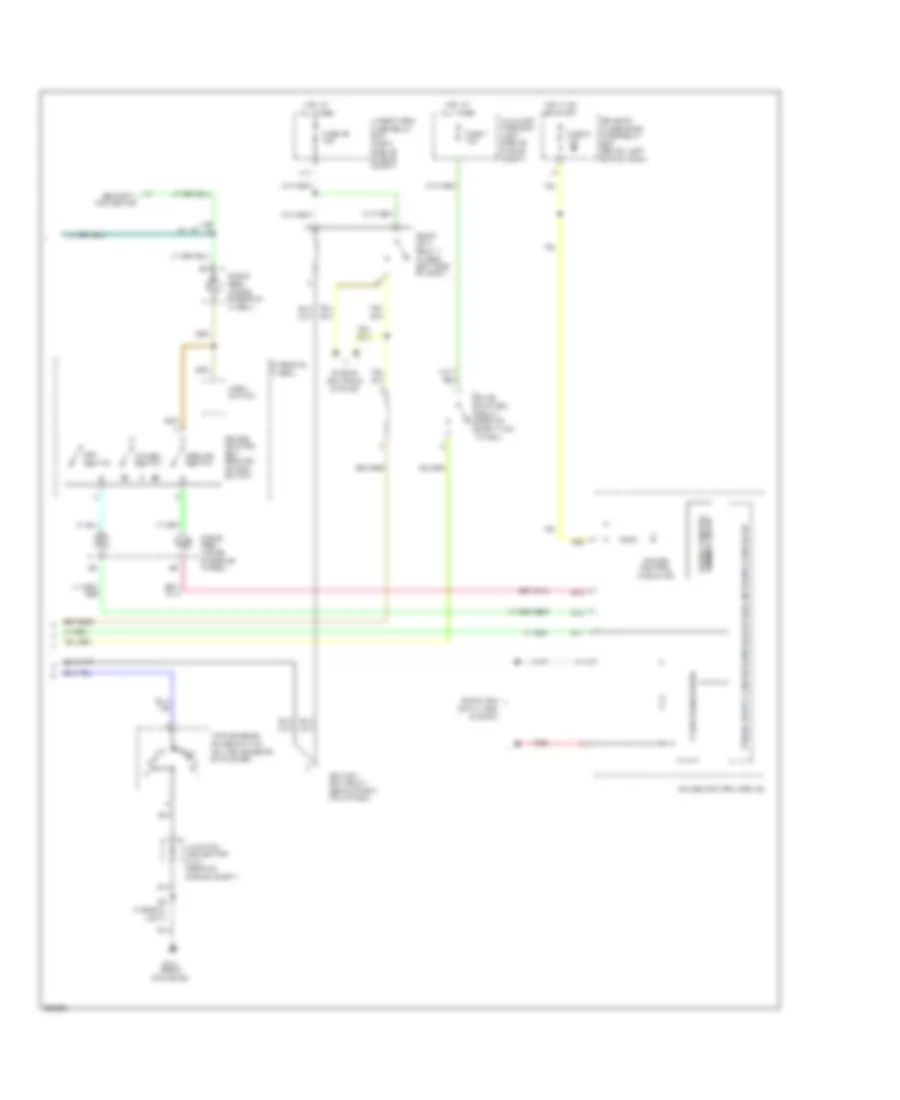
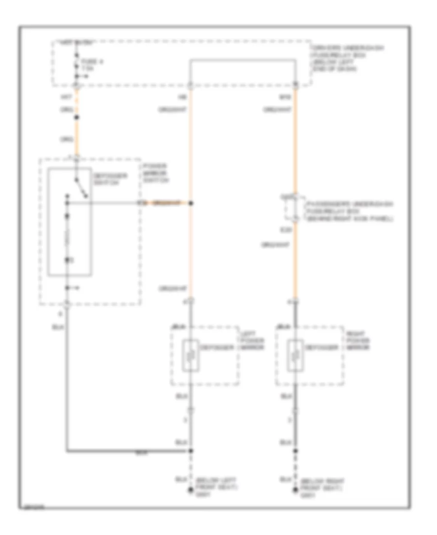
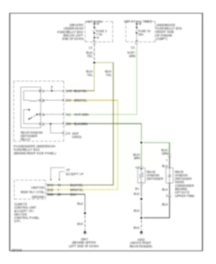
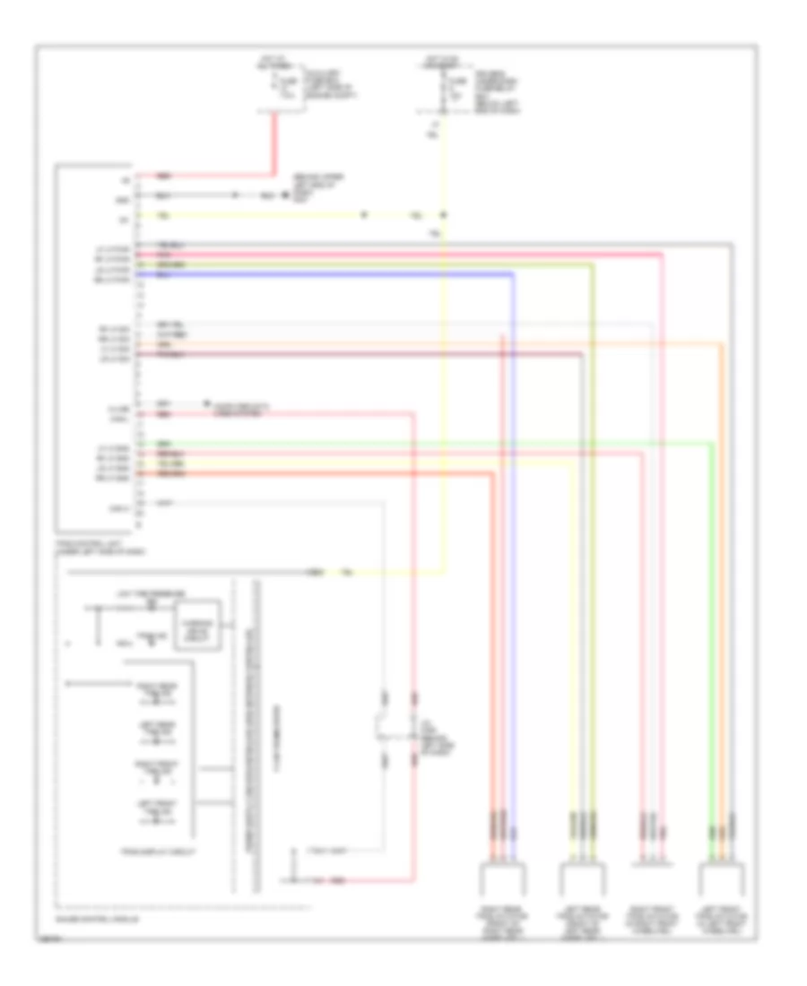
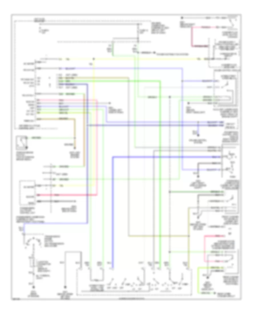
DEFOGGERS
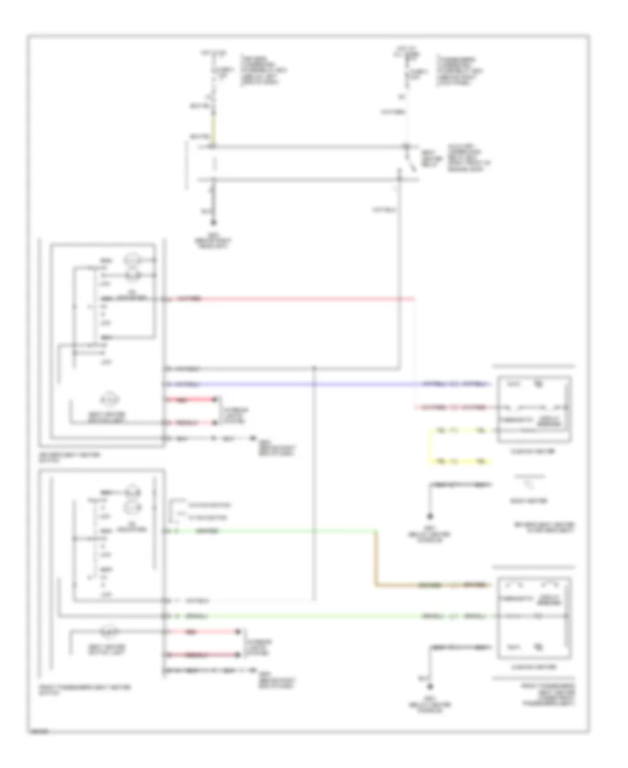
Heated Mirrors Wiring Diagram, USA Except VP & Canada for Honda Pilot SE 2008
List of elements for Heated Mirrors Wiring Diagram, USA Except VP & Canada for Honda Pilot SE 2008:
- (below left front seat) g601
- (below right front seat) g651
- Defogger
- Defogger switch
- Driver's under-dash fuse/relay box (below left end of dash)
- E20
- Fuse 4 7.5a
- G12
- H17
- Hot in on
- Left power mirror
- M18
- Passenger's under-dash fuse/relay box (behind right kick panel)
- Power mirror switch
- Right power mirror
Rear Defogger Wiring Diagram for Honda Pilot SE 2008
List of elements for Rear Defogger Wiring Diagram for Honda Pilot SE 2008:
- (not used)
- B13
- B28
- B29
- Climate control unit (except vp) heater control panel (vp)
- Driver's under-dash fuse/relay box (below left end of dash)
- Except vp
- Fuse 3 7.5a
- Fuse 53 30a
- G401 (behind upper left end of dash)
- G652 (above right rear fender)
- Ground
- Hot at all times
- Hot in on
- I15
- Ignition
- J15
- Passenger's underdash fuse/relay box (behind right kick panel)
- Rdef rly ctrl
- Rear window defogger
- Rear window defogger noise condenser (behind liftgate upper trim)
- Rear window defogger relay
- Underhood fuse/relay box (right side of engine compt)
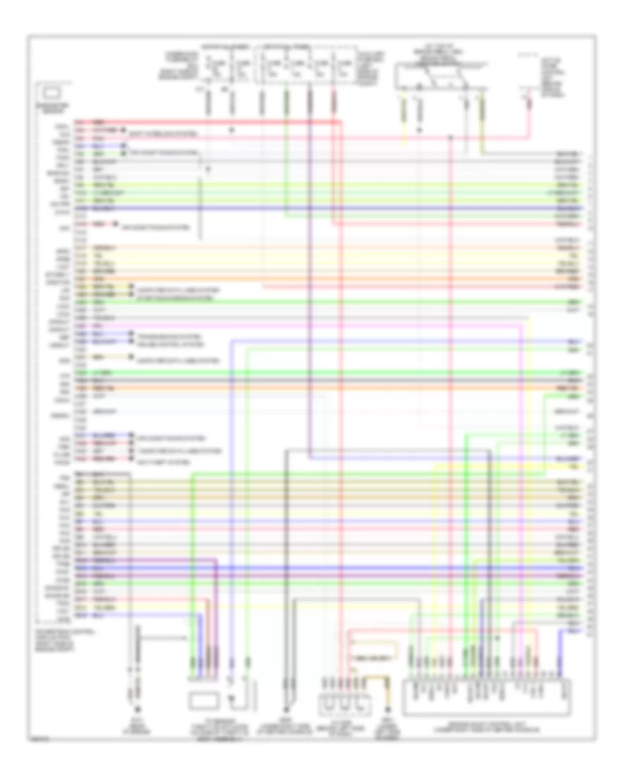
ENGINE PERFORMANCE
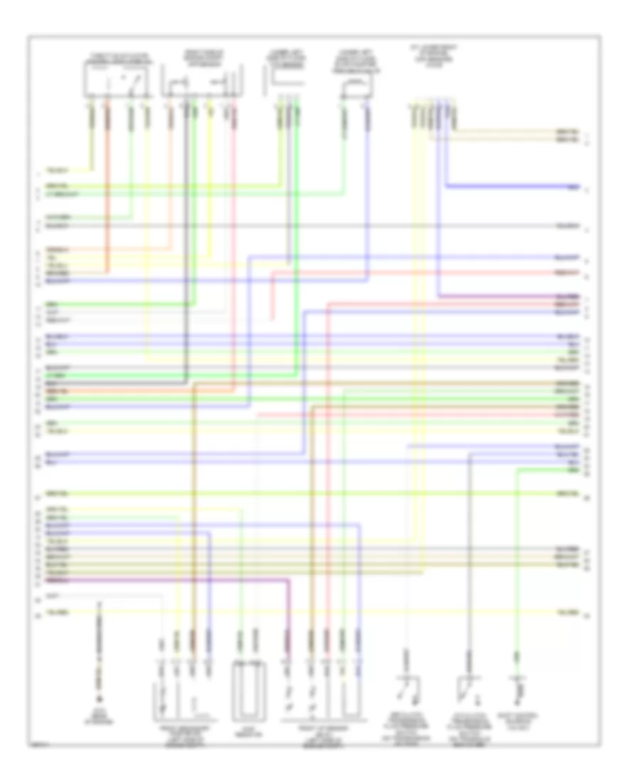
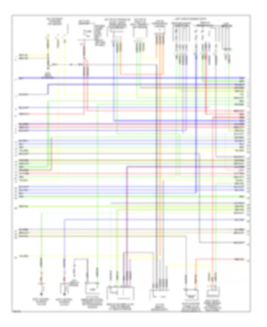
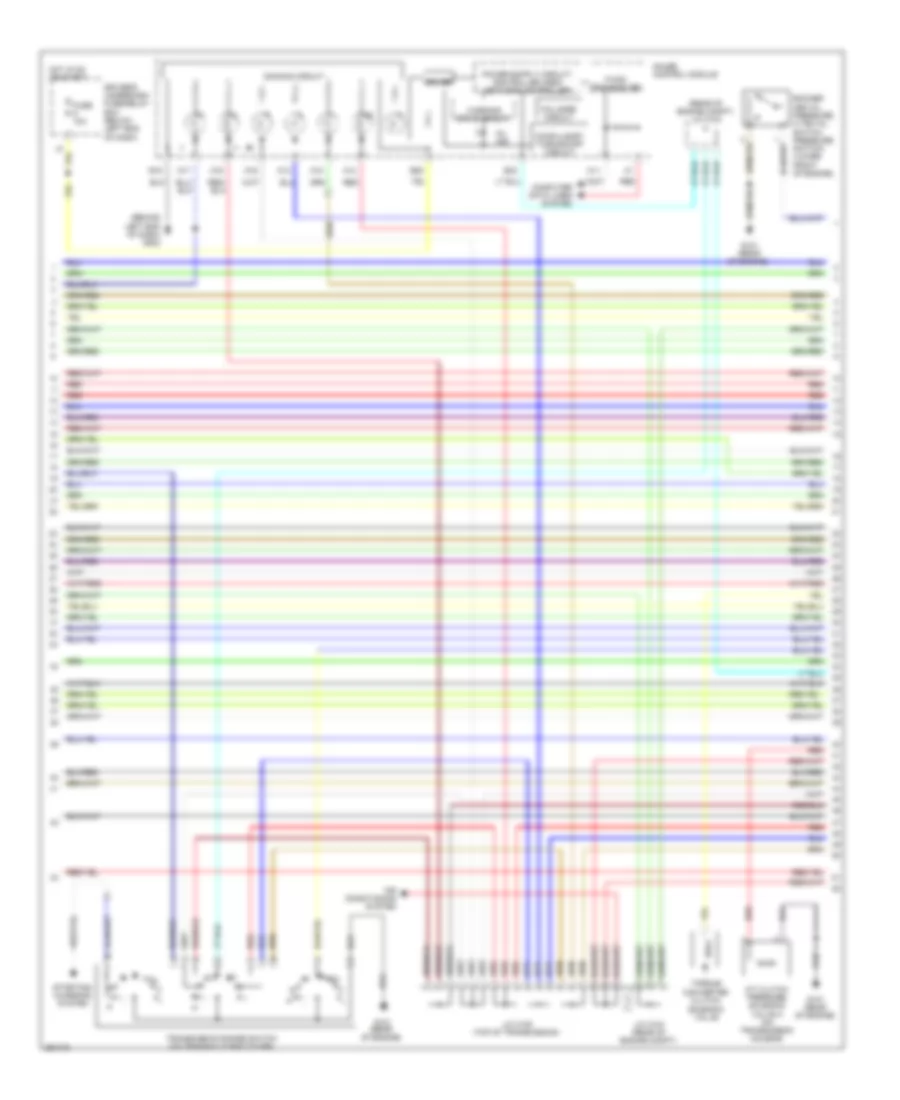
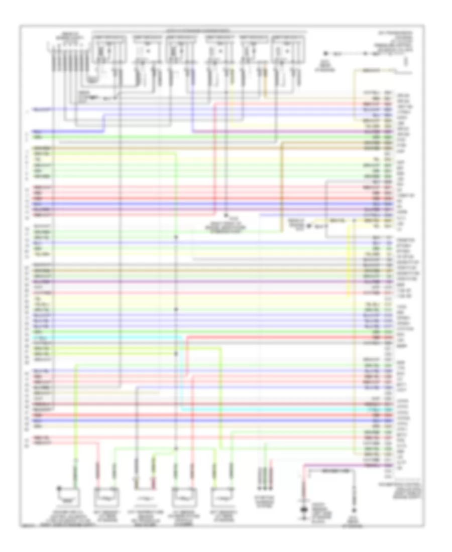
3.5L
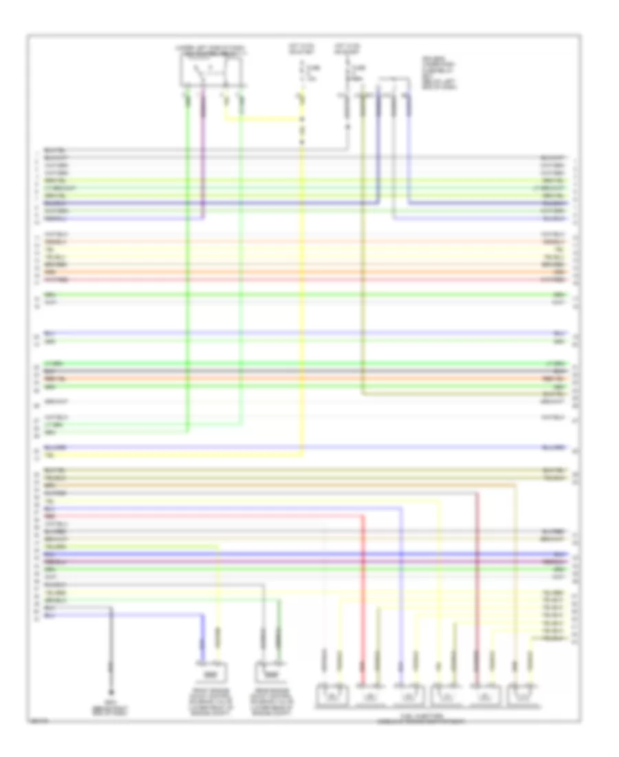
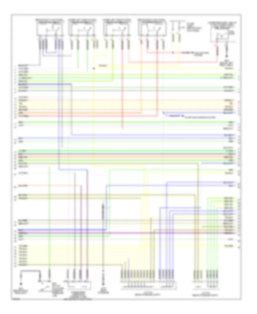
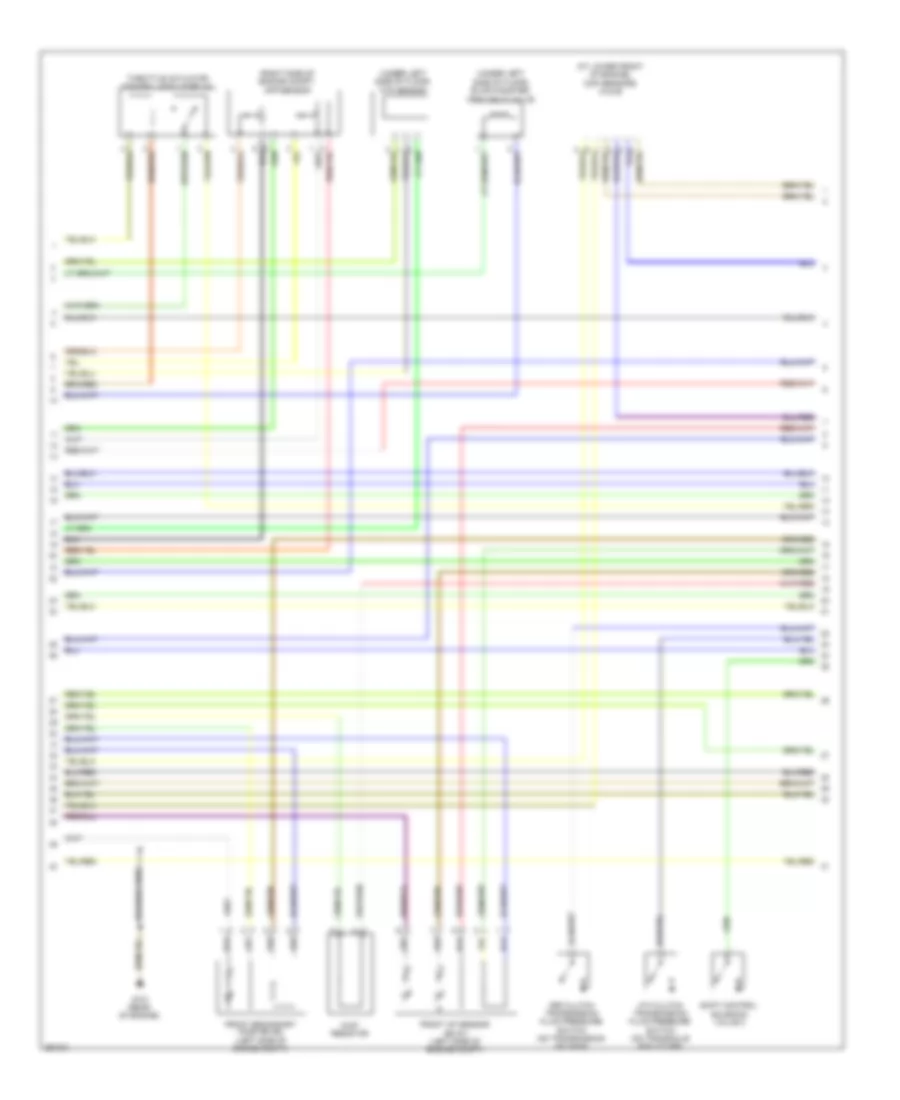
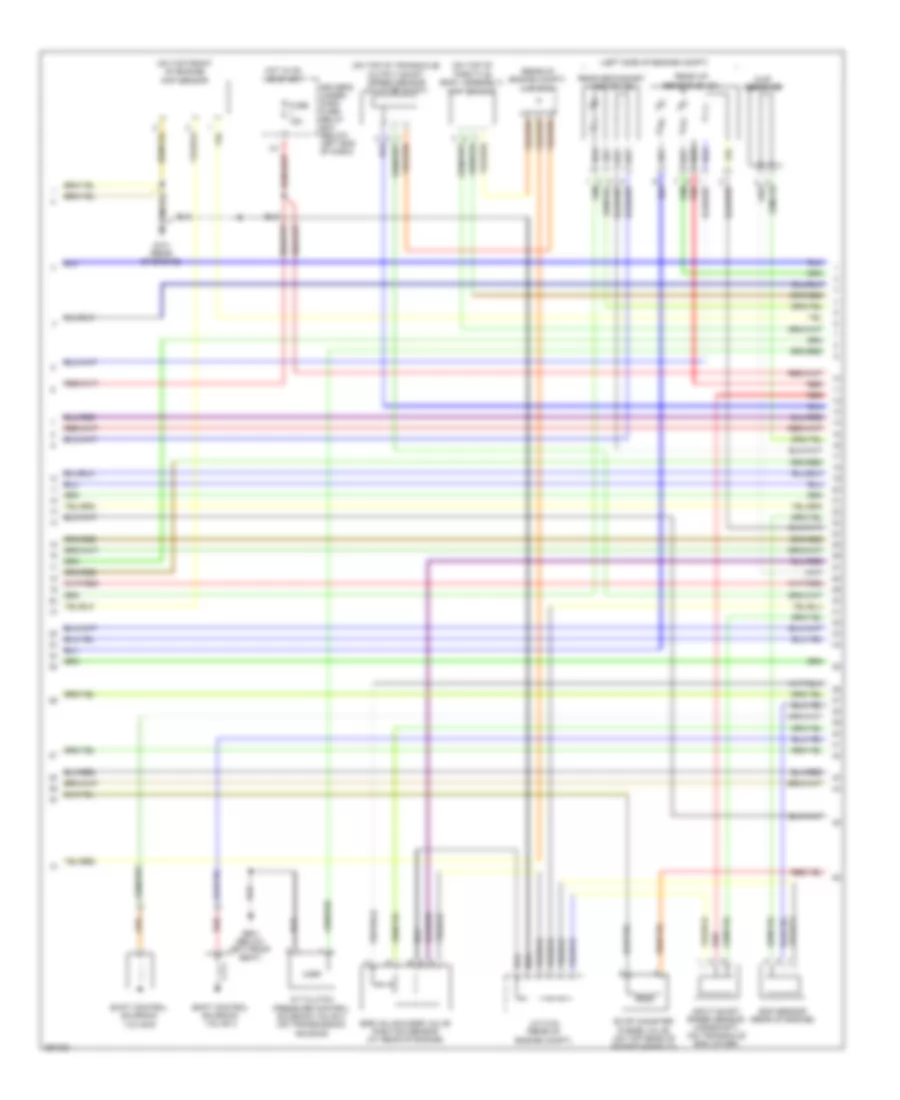
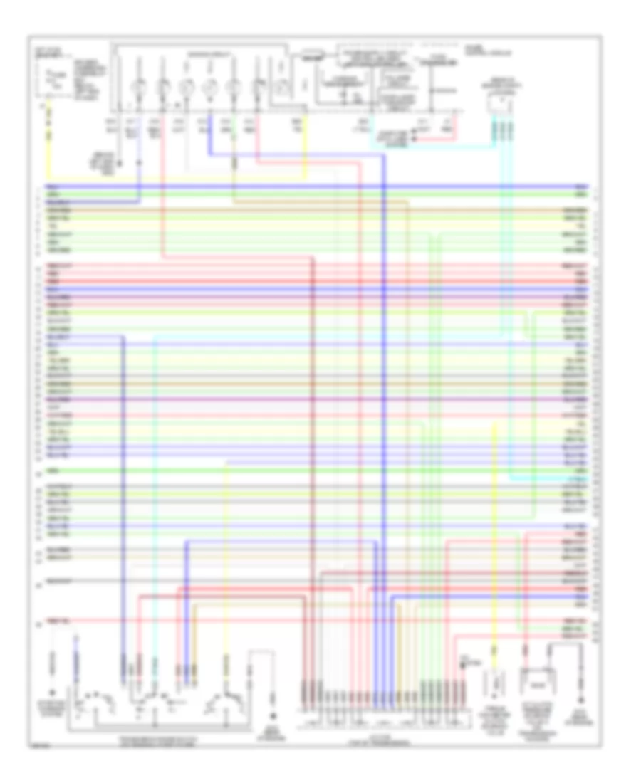
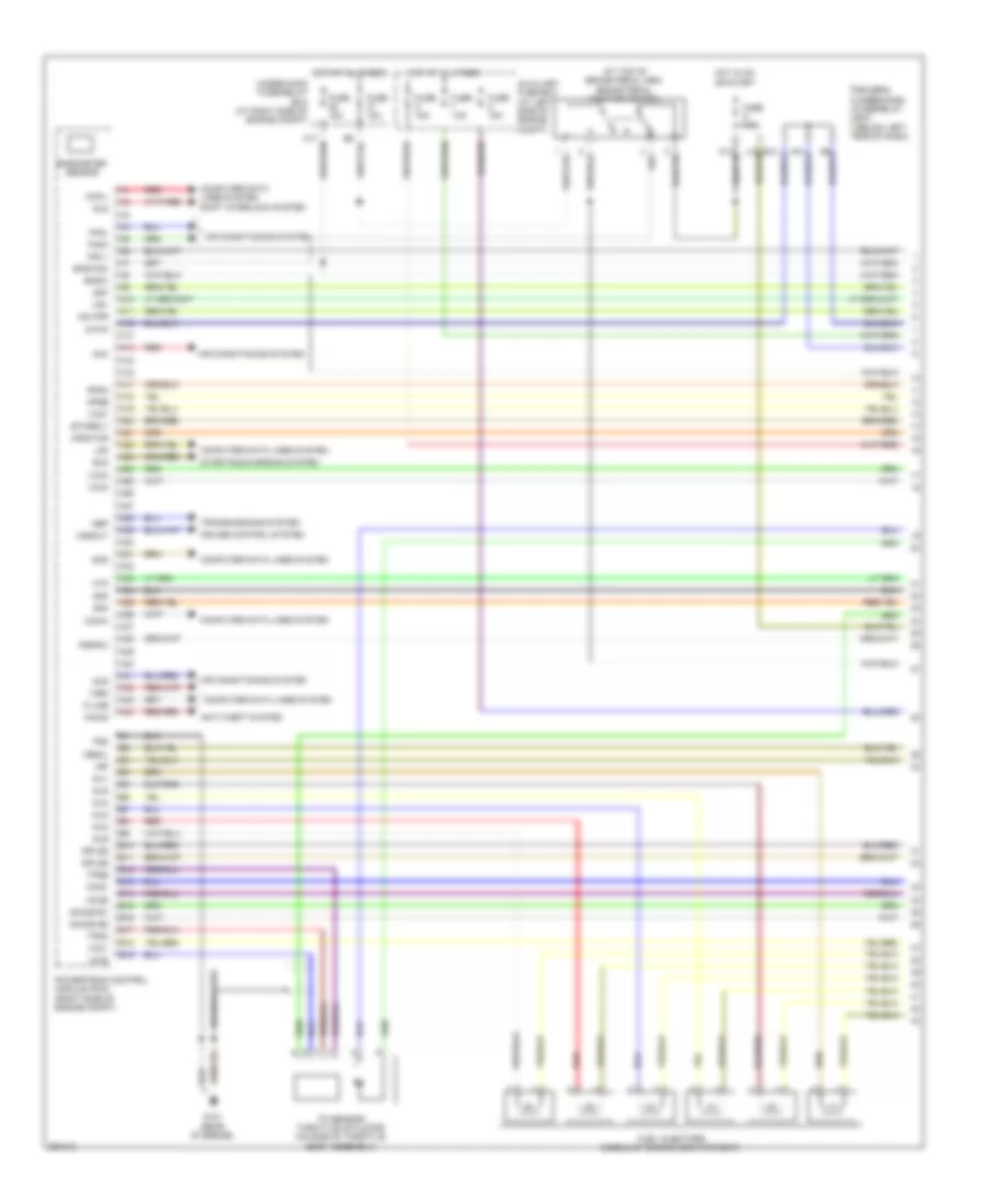
3.5L, Engine Performance Wiring Diagram, 2WD (1 of 7) for Honda Pilot SE 2008
List of elements for 3.5L, Engine Performance Wiring Diagram, 2WD (1 of 7) for Honda Pilot SE 2008:
- (at top of brake pedal arm) brake pedal position switch
- A10
- A11
- A12
- A13
- A14
- A15
- A16
- A17
- A18
- A19
- A20
- A21
- A22
- A23
- A24
- A25
- A26
- A27
- A28
- A29
- A30
- A31
- A32
- A33
- A34
- A35
- A36
- A37
- A38
- A39
- A40
- A41
- A42
- A43
- A44
- Acc
- Acs
- Active noise control unit (behind middle of dash)
- Afshtcr
- Air conditioning system
- Anti-theft system
- Apsa
- Apsb
- Atp-p
- Auxiliary fuse box (left side of engine compt)
- B10
- B11
- B12
- B13
- B14
- B15
- B16
- B17
- B18
- B19
- Barometer sensor
- Bksw
- Bkswnc
- Braided wire
- Can-h
- Can-l
- Ckpout
- Cmpout
- Computer data lines system
- Crk 1
- Cruise control system
- Cssam
- Cyl
- Eld
- Engine mount control unit (under right side of center console)
- Etcsrly
- Fanh
- Fanl
- Ftp
- Fuse 10a
- Fuse 15a
- G101 (rear of engine)
- G501 (under left side of dash)
- G505 (under right side of center console)
- Hot at all times
- Ig1
- Igp
- Igpls5
- Igpls6
- Igsol1
- Igsol2
- Imo fpr
- Imocd
- Inj1
- Inj2
- Inj3
- Inj4
- Inj5
- Inj6
- J/c c306 (behind left side of dash)
- K-line
- Lg3
- Mrly
- Nep
- Pg1
- Pg2
- Pnk
- Powertrain control module (pcm) (right side of engine compt)
- Pspsw
- Red
- Scp
- Scs
- Sg3
- Sg4
- Sg7
- Shift interlock system
- Sho2s b1
- Sho2s b2
- Sls
- Solfm
- Solfp
- Solrly
- Solrm
- Solrp
- Starting/charging system
- Tp sensor/ throttle actuator (on side of throttle body assembly)
- Tpsa
- Tpsb
- Transmissions system
- Under-hood fuse/relay box (right side of engine compt)
- Vbsol
- Vcc1
- Vcc3
- Vcc4
- Vcc5
- Vcc7
- Vs b1
- Vs b2
- Vssout
- Vsv
- Wen
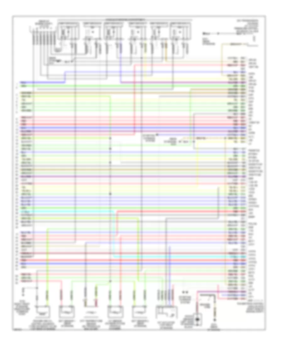
3.5L, Engine Performance Wiring Diagram, 2WD (2 of 7) for Honda Pilot SE 2008
List of elements for 3.5L, Engine Performance Wiring Diagram, 2WD (2 of 7) for Honda Pilot SE 2008:
- (under left side of dash) acm control relay
- Driver's under-dash fuse/relay box (below left end of dash)
- Front engine mount control solenoid valve (lower front of engine compt)
- Fuel injectors (middle of engine compartment)
- Fuse 10a
- Fuse 15a
- G503 (behind right end of dash)
- Hot in on or start
- M14
- Rear engine mount control solenoid valve (lower rear of engine compt)
- Red
3.5L, Engine Performance Wiring Diagram, 2WD (3 of 7) for Honda Pilot SE 2008
List of elements for 3.5L, Engine Performance Wiring Diagram, 2WD (3 of 7) for Honda Pilot SE 2008:
- (behind right kick panel) a/f sensor relay
- (behind right kick panel) ignition coil relay
- (under left side of dash) pgm-fi main relay 1
- (under left side of dash) pgm-fi main relay 2
- (under rear seat, below floor access panel) fuel tank unit
- 7.5a
- Braided wire
- Cooling fans system
- Fuel pump
- G101 (rear of engine)
- G201 (behind right headlight)
- G601 (below left front seat)
- In-line fuse 1 (behind right kick panel)
- J/c c103 (rear of engine compt)
- J/c c104 (rear of engine compt)
- Passenger's under-dash fuse/relay box (behind right kick panel)
- Psp switch (on power steering pressure line)
- Starting/charging system
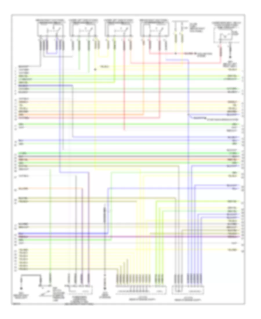
3.5L, Engine Performance Wiring Diagram, 2WD (4 of 7) for Honda Pilot SE 2008
List of elements for 3.5L, Engine Performance Wiring Diagram, 2WD (4 of 7) for Honda Pilot SE 2008:
- (at lower front of engine) ckp sensors (a & b)
- (right side of engine compt) app sensor
- (under left side of floor) evap canister vent shut valve
- (under left side of floor) ftp sensor
- 3rd clutch transmission fluid pressure switch (on transmission housing)
- 4th clutch transmission fluid pressure switch (on transaxle end cover)
- Braided wire
- Chip resistor
- Front a/f sensor (b2 s1) (left side of engine compt)
- Front secondary ho2s (b2 s2) (left side of engine compt)
- G101 (rear of engine)
- Shift control solenoid valve c
- Throttle actuator control module relay
3.5L, Engine Performance Wiring Diagram, 2WD (5 of 7) for Honda Pilot SE 2008
List of elements for 3.5L, Engine Performance Wiring Diagram, 2WD (5 of 7) for Honda Pilot SE 2008:
- (left side of engine compt)
- (on top front of engine) cmp sensor
- (on top of throttle body assembly) map sensor
- (on top of transaxle) output shaft speed sensor (counter shaft)
- (rear of engine compt) j/c c104
- A/t clutch pressure control solenoid valve c (on transmission housing)
- Chip resistor
- Driver's under- dash fuse/ relay box (below left end of dash)
- Egr valve & egr valve position sensor (at rear of engine)
- Eop sensor (rear of engine)
- Evap canister purge valve (on top rear of intake manifold)
- Fuse 15a
- G101 (rear of engine)
- G601 (below left front seat)
- Hot in on or start
- Input shaft speed sensor (mainshaft) (on transaxle end cover)
- J/c c104 (rear of engine compt)
- Rear a/f sensor (b1 s1)
- Rear secondary ho2s (b1 s2)
- Red
- Shift control solenoid valve a
- Shift control solenoid valve b
3.5L, Engine Performance Wiring Diagram, 2WD (6 of 7) for Honda Pilot SE 2008
List of elements for 3.5L, Engine Performance Wiring Diagram, 2WD (6 of 7) for Honda Pilot SE 2008:
- (behind left end of dash) g502
- (rear of engine compt) j/c c104
- A/c system
- A/t clutch pressure solenoid valve a (on transmission housing)
- A11
- A12
- A13
- A14
- A15
- A16
- A17
- B18
- B25
- B33
- Compulsory turning-off circuit
- Computer data lines system
- Dimming circuit
- Driver
- Driver's underdash fuse/relay box (below left end of dash)
- F-can transceiver
- Fail-safe circuit
- Fuse 10a
- G101 (rear of engine)
- Gauge control module
- Hot in on or start
- J/c c105 (top of transmission)
- Mil ind
- Red
- Starting/ charging system
- Torque converter clutch solenoid valve
- Transmission range switch (on transaxle end cover)
- Warning drive circuit
3.5L, Engine Performance Wiring Diagram, 2WD (7 of 7) for Honda Pilot SE 2008
List of elements for 3.5L, Engine Performance Wiring Diagram, 2WD (7 of 7) for Honda Pilot SE 2008:
- (middle of engine compartment)
- (on transmission housing) a/t clutch pressure control solenoid valve b
- (rear of engine compt) j/c c103
- (rear of engine) g101
- Afshtc b1
- Afshtc b2
- Altc
- Altf
- Altl
- Atf temperature sensor (on transaxle end cover)
- Atft
- Atp fwd
- Atp-1
- Atp-2
- Atp-d
- Atp-d3
- Atp-n
- Atp-r
- B20
- B21
- B22
- B23
- B24
- B25
- B26
- B27
- B28
- B29
- B30
- B31
- B32
- B33
- B34
- B35
- B36
- B37
- B38
- B39
- B40
- B41
- B42
- B43
- B44
- Braided wire
- C10
- C11
- C12
- C13
- C14
- C15
- C16
- C17
- C18
- C19
- C20
- C21
- C22
- C23
- C24
- C25
- C26
- C27
- C28
- C29
- C30
- C31
- C32
- C33
- C34
- C35
- C36
- C37
- C38
- C39
- C40
- C41
- C42
- C43
- C44
- Ckpa
- Ckpb
- Cmp
- Ect sensor 1 (rear of engine)
- Ect sensor 2 (rear of engine)
- Ect1
- Ect2
- Egr
- Egrp
- Etcsm+
- Etcsm-
- G101 (rear of engine)
- G102 (right front of engine, near power steering pump)
- Iat
- Iat sensor (on rear intake manifold chamber)
- Icm
- Ig1
- Ig1 etcs
- Ignition coil 1
- Ignition coil 2
- Ignition coil 3
- Ignition coil 4
- Ignition coil 5
- Ignition coil 6
- Igpls1
- Igpls2
- Igpls3
- Igpls4
- Imt actuator (top front of engine)
- Imt+
- Imt-
- Imtm
- Ip b1
- Ip b2
- Knock sensor (left side of engine block)
- Lg1
- Lg2
- Lsa
- Lsb
- Lsc
- Map
- Op3sw
- Op4sw
- Pcs
- Pg1
- Pgmetcs
- Pnk
- Poilcs
- Powertrain control module (pcm) (right side of engine compt)
- Red
- Rocker arm oil control solenoid (vtec solenoid valve) (top rear of engine)
- Sg1
- Sg2
- Sg5
- Sg6
- Sha
- Shb
- Shc
- So2shtc b1
- So2shtc b2
- Starting/ charging system
- Vcc2
- Vcc6
- Vcent b1
- Vect b2
- Vlbl b1
- Vlbl b2
- Vts
3.5L, Engine Performance Wiring Diagram, 4WD (1 of 6) for Honda Pilot SE 2008
List of elements for 3.5L, Engine Performance Wiring Diagram, 4WD (1 of 6) for Honda Pilot SE 2008:
- (at top of brake pedal arm) brake pedal position switch
- A10
- A11
- A12
- A13
- A14
- A15
- A16
- A17
- A18
- A19
- A20
- A21
- A22
- A23
- A24
- A25
- A26
- A27
- A28
- A29
- A30
- A31
- A32
- A33
- A34
- A35
- A36
- A37
- A38
- A39
- A40
- A41
- A42
- A43
- A44
- Acc
- Acs
- Afshtcr
- Air conditioning system
- Anti-theft system
- Apsa
- Apsb
- Atp-p
- Auxiliary fuse box (at left side of engine compt)
- B10
- B11
- B12
- B13
- B14
- B15
- B16
- B17
- B18
- B19
- Barometer sensor
- Bksw
- Bkswnc
- Braided wire
- Can-h
- Can-l
- Computer data lines system
- Cruise control system
- Driver's under-dash fuse/relay box (below left end of dash)
- Eld
- Etcsrly
- Fanh
- Fanl
- Ftp
- Fuel injectors (middle of engine compartment)
- Fuse 15a
- G101 (rear of engine)
- Hot at all times
- Hot in on or start
- Igp
- Igpls5
- Igpls6
- Imo fpr
- Imocd
- Inj1
- Inj2
- Inj3
- Inj4
- Inj5
- Inj6
- K-line
- Lg3
- Mrly
- Nep
- Pg2
- Powertrain control module (pcm) (right side of engine compt)
- Pspsw
- Red
- Scs
- Sg3
- Sg4
- Sg7
- Shift interlock system
- Sho2s b1
- Sho2s b2
- Sls
- Starting/charging system
- Tp sensor/ throttle actuator (on side of throttle body assembly)
- Tpsa
- Tpsb
- Transmissions system
- Under-hood fuse/relay box (at right side of engine compt)
- Vbsol
- Vcc1
- Vcc3
- Vcc4
- Vcc5
- Vcc7
- Vs b1
- Vs b2
- Vssout
- Vsv
- Wen
3.5L, Engine Performance Wiring Diagram, 4WD (2 of 6) for Honda Pilot SE 2008
List of elements for 3.5L, Engine Performance Wiring Diagram, 4WD (2 of 6) for Honda Pilot SE 2008:
- (behind right kick panel) a/f sensor relay
- (behind right kick panel) ignition coil relay
- (under left side of dash) pgm-fi main relay 1
- (under left side of dash) pgm-fi main relay 2
- (under rear seat, below floor access panel) fuel tank unit
- 7.5a
- Braided wire
- Cooling fans system
- Fuel pump
- G101 (rear of engine)
- G201 (behind right headlight)
- G601 (below left front seat)
- In-line fuse 1 (behind right kick panel)
- J/c c103 (rear of engine compt)
- J/c c104 (rear of engine compt)
- Passenger's under-dash fuse/relay box (behind right kick panel)
- Psp switch (on power steering pressure line)
- Starting/charging system
3.5L, Engine Performance Wiring Diagram, 4WD (3 of 6) for Honda Pilot SE 2008
List of elements for 3.5L, Engine Performance Wiring Diagram, 4WD (3 of 6) for Honda Pilot SE 2008:
- (at lower front of engine) ckp sensors (a & b)
- (right side of engine compt) app sensor
- (under left side of floor) evap canister vent shut valve
- (under left side of floor) ftp sensor
- 3rd clutch transmission fluid pressure switch (on transmission housing)
- 4th clutch transmission fluid pressure switch (on transaxle end cover)
- Braided wire
- Chip resistor
- Front a/f sensor (b2 s1) (left side of engine compt)
- Front secondary ho2s (b2 s2) (left side of engine compt)
- G101 (rear of engine)
- Shift control solenoid valve c
- Throttle actuator control module relay
3.5L, Engine Performance Wiring Diagram, 4WD (4 of 6) for Honda Pilot SE 2008
List of elements for 3.5L, Engine Performance Wiring Diagram, 4WD (4 of 6) for Honda Pilot SE 2008:
- (left side of engine compt)
- (on top front of engine) cmp sensor
- (on top of throttle body assembly) map sensor
- (on top of transaxle) output shaft speed sensor (counter shaft)
- (top of transmission) j/c c105
- A/t clutch pressure control solenoid valve c (on transmission housing)
- Chip resistor
- Driver's under- dash fuse/ relay box (below left end of dash)
- Egr valve & egr valve position sensor (at rear of engine)
- Evap canister purge valve (on top rear of intake manifold)
- Fuse 15a
- G101 (rear of engine)
- Hot in on or start
- Input shaft speed sensor (mainshaft) (on transaxle end cover)
- J/c c104 (rear of engine compt)
- Rear a/f sensor (b1 s1)
- Rear secondary ho2s (b1 s2)
- Red
- Shift control solenoid valve a
- Shift control solenoid valve b
3.5L, Engine Performance Wiring Diagram, 4WD (5 of 6) for Honda Pilot SE 2008
List of elements for 3.5L, Engine Performance Wiring Diagram, 4WD (5 of 6) for Honda Pilot SE 2008:
- (behind left end of dash) g502
- (rear of engine compt) j/c c104
- A/t clutch pressure solenoid valve a (on transmission housing)
- A11
- A12
- A13
- A14
- A15
- A16
- A17
- Air conditioning system
- B18
- B25
- B33
- Compulsory turning-off circuit
- Computer data lines system
- Dimming circuit
- Driver
- Driver's underdash fuse/relay box (below left end of dash)
- F-can transceiver
- Fail-safe circuit
- Fuse 10a
- G101 (rear of engine)
- Gauge control module
- Hot in on or start
- J/c c104 (rear of engine compt)
- J/c c105 (top of transmission)
- Mil ind
- Red
- Rocker arm oil pressure (vtec oil switch pressure switch) (lower front of engine)
- Starting/ charging system
- Torque converter clutch solenoid valve
- Transmission range switch (on transaxle end cover)
- Warning drive circuit
3.5L, Engine Performance Wiring Diagram, 4WD (6 of 6) for Honda Pilot SE 2008
List of elements for 3.5L, Engine Performance Wiring Diagram, 4WD (6 of 6) for Honda Pilot SE 2008:
- (middle of engine compartment)
- (on transmission housing) a/t clutch pressure control solenoid valve b
- (rear of engine compt) j/c c103
- (rear of engine) g101
- (right front of engine, near power steering pump)
- Afshtc b1
- Afshtc b2
- Altc
- Altf
- Altl
- Atf temperature sensor (on transaxle end cover)
- Atft
- Atp fwd
- Atp-1
- Atp-2
- Atp-d
- Atp-d3
- Atp-n
- Atp-r
- B20
- B21
- B22
- B23
- B24
- B25
- B26
- B27
- B28
- B29
- B30
- B31
- B32
- B33
- B34
- B35
- B36
- B37
- B38
- B39
- B40
- B41
- B42
- B43
- B44
- Braided wire
- C10
- C11
- C12
- C13
- C14
- C15
- C16
- C17
- C18
- C19
- C20
- C21
- C22
- C23
- C24
- C25
- C26
- C27
- C28
- C29
- C30
- C31
- C32
- C33
- C34
- C35
- C36
- C37
- C38
- C39
- C40
- C41
- C42
- C43
- C44
- Ckpa
- Ckpb
- Cmp
- Ect sensor 1 (at rear of engine)
- Ect sensor 2 (at rear of engine)
- Ect1
- Ect2
- Egr
- Egrp
- Etcsm+
- Etcsm-
- G101 (rear of engine)
- G102
- Iat
- Iat sensor (on rear intake manifold chamber)
- Icm
- Ig1
- Ig1 etcs
- Ignition coil 1
- Ignition coil 2
- Ignition coil 3
- Ignition coil 4
- Ignition coil 5
- Ignition coil 6
- Igpls1
- Igpls2
- Igpls3
- Igpls4
- Ip b1
- Ip b2
- Knock sensor (left side of engine block)
- Lg1
- Lg2
- Lsa
- Lsb
- Lsc
- Map
- Op3sw
- Op4sw
- Pcs
- Pg1
- Pgmetcs
- Pnk
- Powertrain control module (pcm) (right side of engine compt)
- Red
- Rocker arm oil control solenoid (vtec solenoid valve) (right side of engine compt)
- Sg1
- Sg2
- Sg5
- Sg6
- Sha
- Shb
- Shc
- So2shtc b1
- So2shtc b2
- Starting/ charging system
- Vcc2
- Vcent b1
- Vect b2
- Vlbl b1
- Vlbl b2
- Vtpsw
- Vts
EXTERIOR LIGHTS
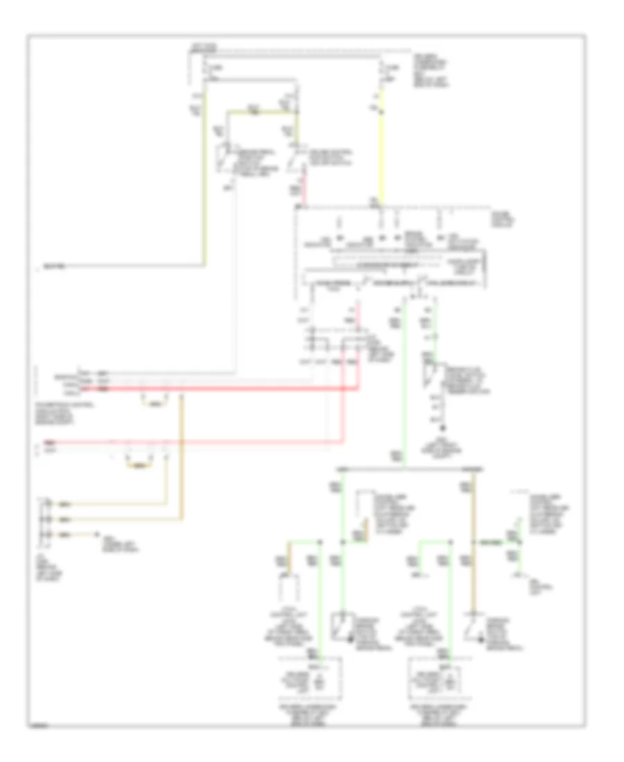
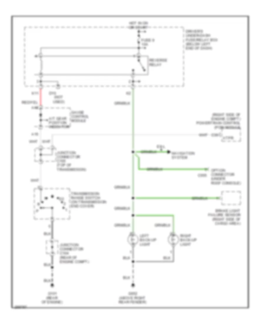
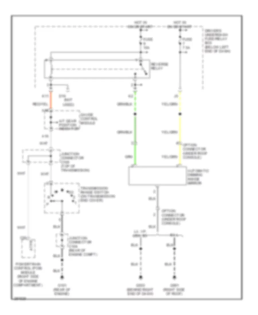
Back-up Lamps Wiring Diagram for Honda Pilot SE 2008
List of elements for Back-up Lamps Wiring Diagram for Honda Pilot SE 2008:
- (not
- (right side of engine compt) powertrain control (pcm) module
- (under roof console)
- A/t gear position indicator
- A16
- A18
- Atpr
- Brake light failure sensor (right side of cargo area)
- C30
- D10
- Driver's under-dash fuse/relay box (below left end of dash)
- Ex-l
- Fuse 9 10a
- G101 (rear of engine)
- G652 (above right rear fender)
- Gauge control module
- Hot in on or start
- Junction connector c104 (rear of engine compt)
- Junction connector c105 (top of transmission)
- K11
- Left back-up light
- Navigation system
- Option connector c555
- Reverse relay
- Right back-up light
- Transmission range switch (on transmission end cover)
- Used)
Exterior Lamps Wiring Diagram (1 of 2) for Honda Pilot SE 2008
List of elements for Exterior Lamps Wiring Diagram (1 of 2) for Honda Pilot SE 2008:
- (below left end of dash) driver's under-dash fuse/relay box
- A22
- B16
- B17
- Back-up lamps circuit
- Brake light failure sensor (right side of cargo area)
- Brake light/ taillight
- Brake pedal position switch (top of brake pedal arm)
- C13
- C18
- Driver's multiplex control unit
- Fuse 10a
- Fuse 15a
- Fuse 20a
- Fuse 7.5a
- G401 (behind upper left end of dash)
- G652 (above right rear fender)
- H15
- High mount brake light
- Hot at all times
- Hot in on or start
- Interior lights systems
- J/c c207 (behind glove box)
- J16
- L15
- L21
- Left taillight assembly
- License plate light
- Lx & vp
- M20
- Passenger's under-dash fuse/relay box (behind right kick panel)
- Rear side marker light
- Right taillight assembly
- Security connector (lx)
- Sml rly+
- Sml rly-
- Stop sw
- Taillight relay (under left side of dash)
- Turn signal light/ taillight
- Turn signal/ hazard relay
- Underhood fuse/relay box (right side of engine compt)
- Usa: ex, se & ex-l
Exterior Lamps Wiring Diagram (2 of 2) for Honda Pilot SE 2008
List of elements for Exterior Lamps Wiring Diagram (2 of 2) for Honda Pilot SE 2008:
- (behind left end of dash) g502
- (behind upper left end of dash) g401
- (not used)
- 7.5a
- A19
- B22
- B26
- Combination light switch
- D18
- Driver's under-dash fuse/relay box (below left end of dash)
- Fuse 20a
- G201 (behind right headlight)
- G301 (left front side of engine compt)
- G401 (behind upper left end of dash)
- G503 (behind right end of dash)
- G652 (above right rear fender)
- Gauge control module
- Hazard warning switch
- Hazard warning switch light
- Head
- Headlight switch
- Hot at all times
- Interior lights system
- J13
- L17
- Left front parking light
- Left front side marker light
- Left front turn signal light
- Left side turn signal light
- Left turn signal ind
- Off
- Park
- Red
- Right front parking light
- Right front side marker light
- Right front turn signal light
- Right side turn signal light
- Right turn signal ind
- Safety indicator
- Trailer connector
- Trailer lighting connector (left side of cargo area)
- Trailer lighting control unit
- Trailer lighting in-line fuse 1
- Trailer lighting in-line fuse 2
- Turn signal light switch
- Underhood fuse/relay box (right side of engine compt)
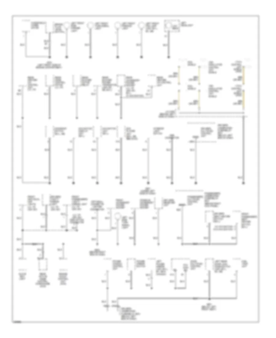
GROUND DISTRIBUTION
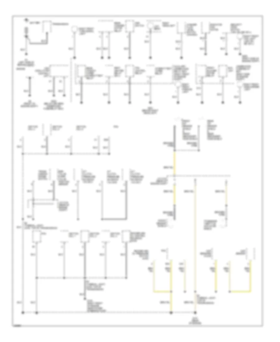
Ground Distribution Wiring Diagram (1 of 4) for Honda Pilot SE 2008
List of elements for Ground Distribution Wiring Diagram (1 of 4) for Honda Pilot SE 2008:
- A/t clutch pressure solenoid valve a
- A/t clutch pressure solenoid valve b
- A/t clutch pressure solenoid valve c
- Auxiliary under-hood relay box (right front of engine compt)
- B36
- B43
- Battery
- Braided wire
- C40
- Ckp sensors (a & b)
- Cmp sensor
- D14
- Egr valve & egr valve position sensor
- Eld unit
- Engine
- Fan control relay
- Front a/f sensor shield & front secondary ho2s shield
- Front blower motor relay
- G1 (left side of engine compt)
- G101 (rear of engine)
- G102 (right front of engine, near power steering pump)
- G2 (front of engine compt)
- G201 (behind right headlight)
- G202 (right side of engine compt)
- G302 (below driver's under-dash fuse/relay box)
- Ignition coil 1
- Ignition coil 2
- Ignition coil 3
- Ignition coil 4
- Ignition coil 5
- Ignition coil 6
- Intermittent wiper relay
- J/c c104 (rear of engine comp)
- J/c c104 (rear of engine compt)
- Knock sensor shield
- Low beam
- Pcm
- Psp switch
- Radiator fan motor
- Rear a/f sensor shield & rear secondary ho2s shield
- Rear washer motor relay
- Rear window wiper intermittent relay
- Right front fog light (usa: ex, se, ex-l)
- Right front parking light
- Right front side marker light
- Right front turn signal light
- Right headlight
- Rocker arm oil control solenoid (2wd)
- Rocker arm oil pressure switch (4wd)
- S2 (thermal joint) (4wd: top of transmission)
- S3 (thermal joint) (4wd: top of transmission)
- S4 (thermal joint) (top of transmission)
- Seat heater relay (ex-l)
- Security hood switch (usa: ex, se, ex-l)
- Tp sensor/ throttle actuator shield
- Trans- mission range switch
- Transmission
- Under-hood fuse/relay box (right side of engine compt)
- Vsa modulator control unit
- Washer fluid level switch (canada)
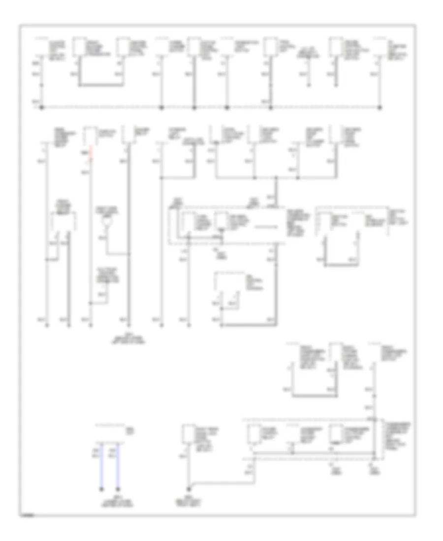
Ground Distribution Wiring Diagram (2 of 4) for Honda Pilot SE 2008
List of elements for Ground Distribution Wiring Diagram (2 of 4) for Honda Pilot SE 2008:
- (lx, vp, usa: ex)
- (lx, vp, usa: ex) c555 option connector
- (optional) cigarette lighter connector
- (w/ navigation)
- (w/o navigation)
- A12
- A13
- B11
- B22
- Brake fluid level switch
- Console accessory power socket
- Door multiplex control unit
- Driver's multiplex control unit
- Driver's seat heater switch (ex-l)
- Driver's under-dash fuse/relay box (below left end of dash)
- Driver's vanity mirror light
- Dvd player unit (ex-l, se, res (dvd))
- Engine mount control unit (2wd)
- F10
- Front accessory power socket
- Front individual map lights
- Front passenger's seat heater switch (ex-l)
- Front passenger's vanity mirror light (lx, vp, usa: ex)
- Fuel tank unit
- G301 (left front side of engine compartment)
- G501 (under left side of dash)
- G503 (behind right end of dash)
- G601 (below left front seat)
- Glove box light
- Interior light switch
- J/c c306 (behind left side of dash)
- Keyless receiver unit
- Left front fog lamp (usa: ex-l, ex, se)
- Left front parking light
- Left front side marker light
- Left front turn signal light
- Left headlight
- Left power mirror (usa: ex-l, ex, se & canada)
- Left rear door lock knob switch (usa: ex-l, ex, se)
- Left side turn signal light
- Low beam
- Mes connector
- Moonroof switch (ex-l, se)
- Navigation display unit (ex-l)
- Navigation unit (ex-l)
- P/w main sw
- Passenger's multiplex control unit
- Passenger's under-dash fuse/relay box (behind right kick panel)
- Pcm shield
- Power mirror switch
- Power window control unit
- Rear accessory power socket (lx, vp, usa: ex, ex-l, w/ navigation)
- Rear active noise control microphone (2wd)
- Rear blower motor relay
- Rear blower power transistor (usa: ex, se, ex-l)
- Rear heater- a/c control unit
- Rear heater- a/c control unit (lx, vp)
- Rear mode control motor (lx, vp)
- Sgnd
- Vsa modulator control unit shield
- Vtm-4 control unit shield (4wd)
- Windshield wiper motor
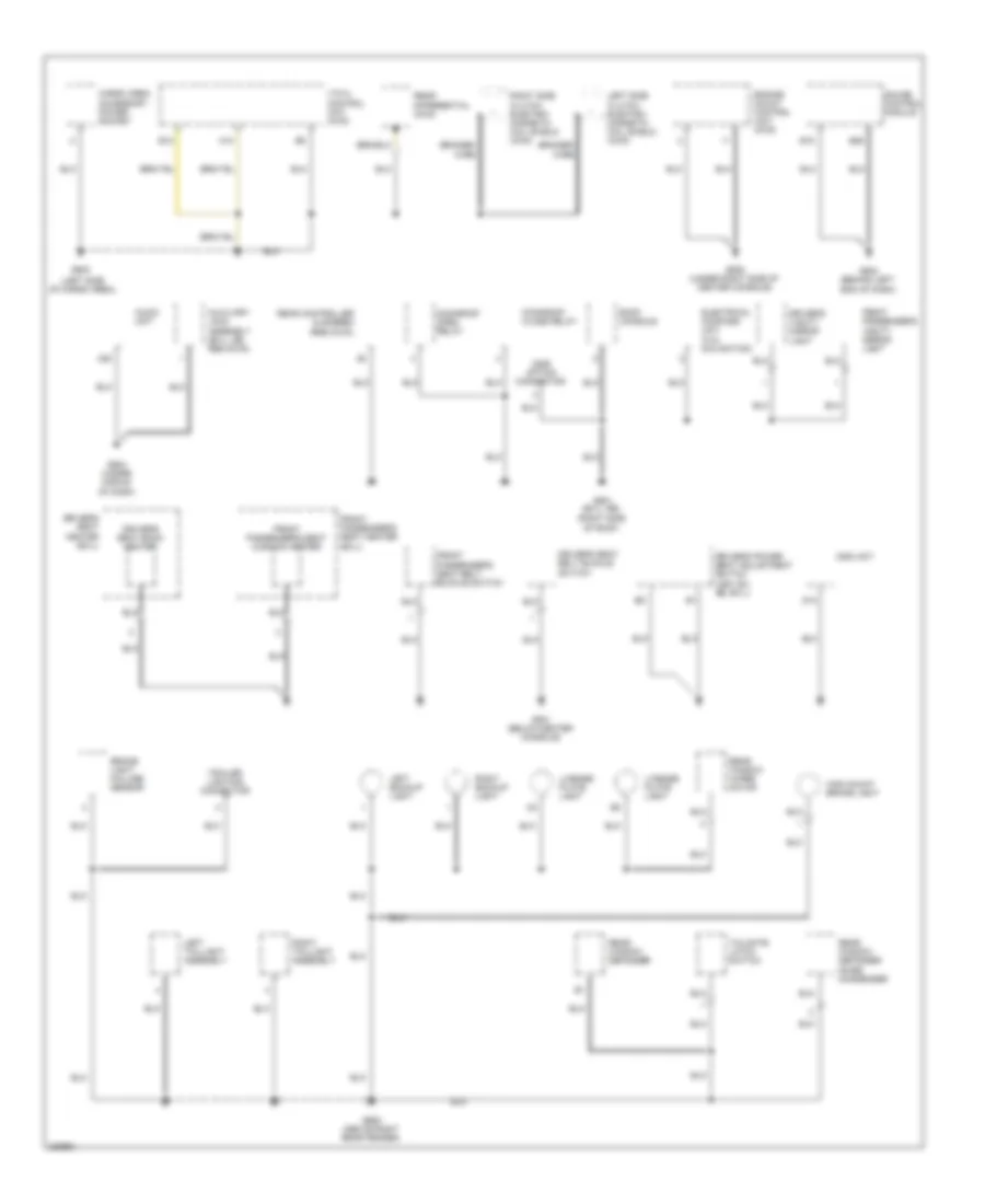
Ground Distribution Wiring Diagram (3 of 4) for Honda Pilot SE 2008
List of elements for Ground Distribution Wiring Diagram (3 of 4) for Honda Pilot SE 2008:
- (lx, vp) security connector
- (not used)
- A12
- A14
- A22
- A23
- Ac inverter unit (res (dvd), se, ex-l)
- Accessory power socket relay
- Active noise control unit (2wd)
- B29
- Climate control unit (usa: ex, se, ex-l)
- Combination light switch
- Cruise control main switch/ vsa off switch
- Data link connector
- Dimmer relay
- Door multiplex control unit
- Driver's door key cylinder switch
- Driver's door lock knob switch
- Driver's door lock switch
- Driver's multiplex control unit
- Driver's under-dash fuse/relay box box (behind left end of dash)
- Drl control unit (canada)
- Front blower power transistor
- Front passenger's door lock knob switch (usa: ex, se, ex-l)
- Front passenger's door lock switch
- Front washer motor relay
- G401 (behind upper left end of dash)
- G651 (below right front seat)
- G802 (under lower center of dash)
- Gnd
- H16
- Heater control panel (lx, vp)
- Ignition key switch
- Ignition key switch/ key light
- Interior light relay
- Key interlock solenoid
- L15
- Multiplex control inspection connextor
- Park pin switch
- Passenger's multiplex control unit
- Passenger's under-dash fuse/relay box (behind right kick panel)
- Power window relay
- Rear accessory power socket relay
- Red
- Right power mirror (usa: ex, se, ex-l & canada)
- Right rear door lock knob switch (usa: ex, se, ex-l)
- Right side turn signal light
- Srs unit
- Tpms control unit
- Turn signal/ hazard relay
- Wiper/ washer switch
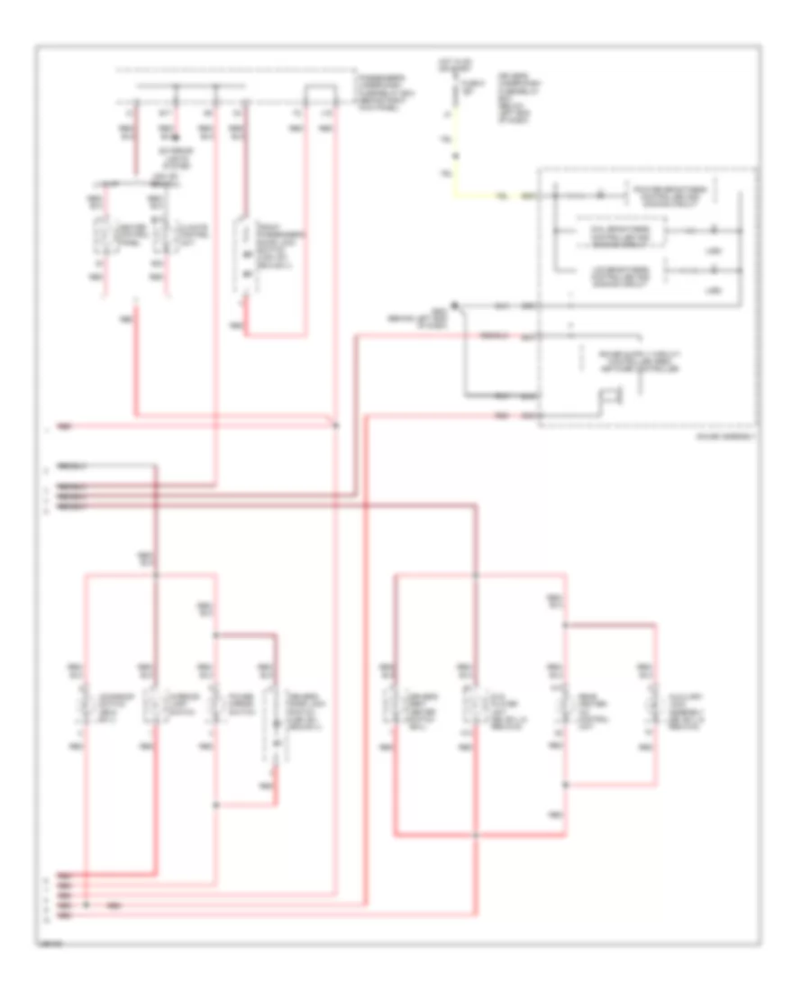
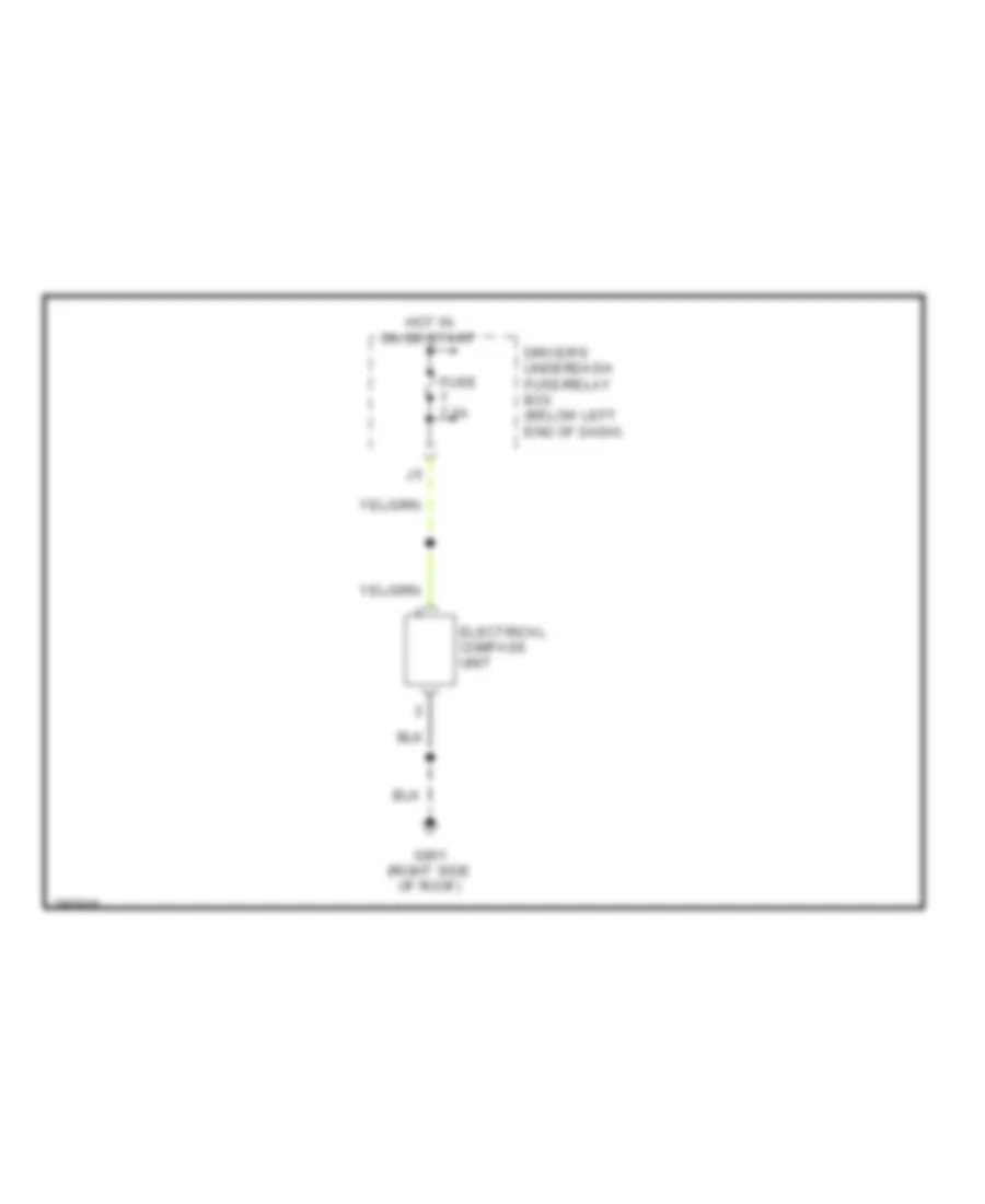
Ground Distribution Wiring Diagram (4 of 4) for Honda Pilot SE 2008
List of elements for Ground Distribution Wiring Diagram (4 of 4) for Honda Pilot SE 2008:
- (left side of cargo area)
- (right side of roof)
- A10
- A20
- Audio unit
- Auxiliary jack assembly (ex-l, se, res (dvd))
- B12
- B18
- B26
- Braided
- Brake light failure sensor
- C555 option connector
- Cargo area accessory power socket
- D12
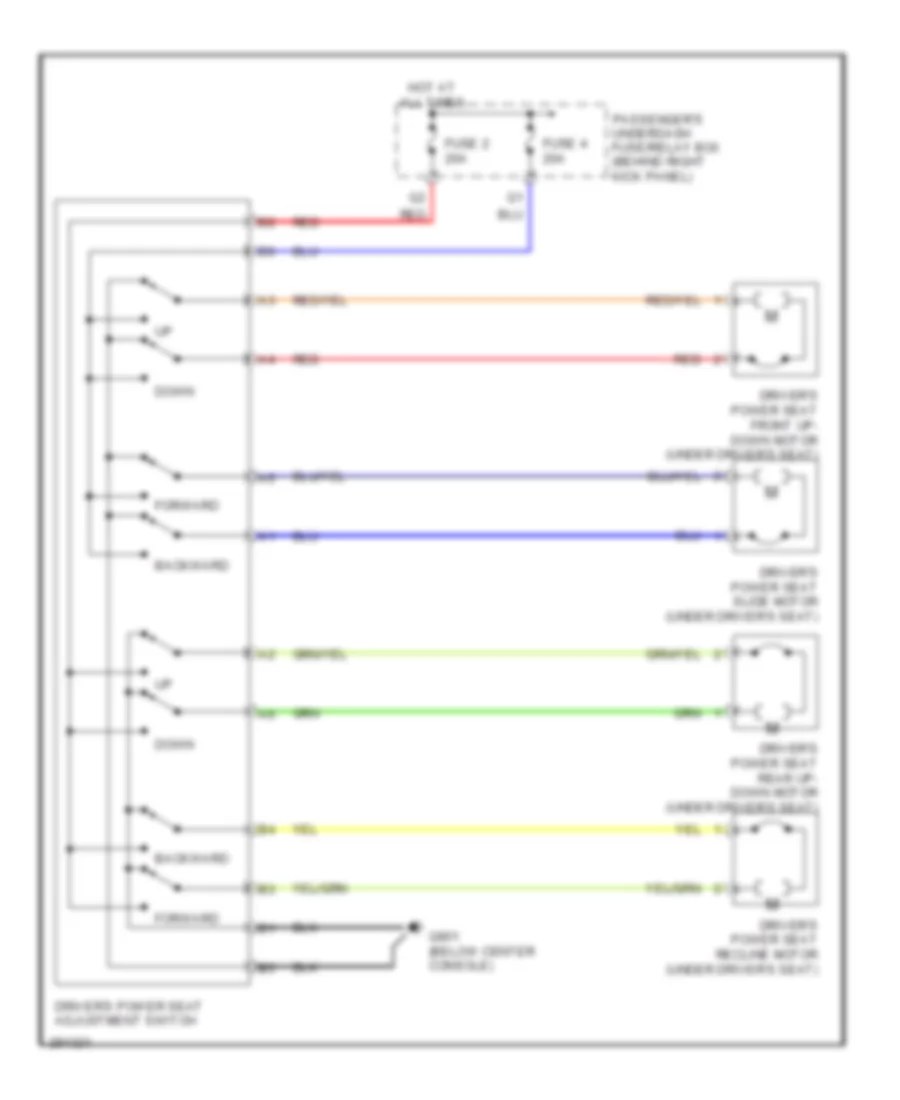
- Driver's power seat adjustment switch (usa: ex, se, ex-l)
- Driver's seat back heater
- Driver's seat belt buckle switch
- Driver's seat heater (ex-l)
- Driver's vanity mirror light
- Electrical compass unit (w/o navigation)
- Engine mount control unit (2wd)
- Front passenger's seat belt buckle switch
- Front passenger's seat cushion heater
- Front passenger's seat heater (ex-l)
- Front passenger's vanity mirror light
- G502 (behind left end of dash)
- G504 (under middle of dash)
- G505 (under right side of center console)
- G602
- G652 (above right rear fender)
- G801 (below center console)
- G901 (ex-l, se)
- Gauge control module
- High mount brake light
- Left backup light
- Left side clutch electro- magnetic coil shield (4wd)
- Left taillight assembly
- License plate light
- Moonroof close relay
- Moonroof open relay
- Ods unit
- Rear controller & screen (res (dvd))
- Rear differential (4wd)
- Rear window defogger
- Rear window defogger noise condenser
- Rear window wiper motor
- Right backup light
- Right side clutch electro- magnetic coil shield (4wd)
- Right taillight assembly
- Roof console
- Tailgate latch switch
- Trailer lighting connector
- Vtm-4 control unit (4wd)
- Wire
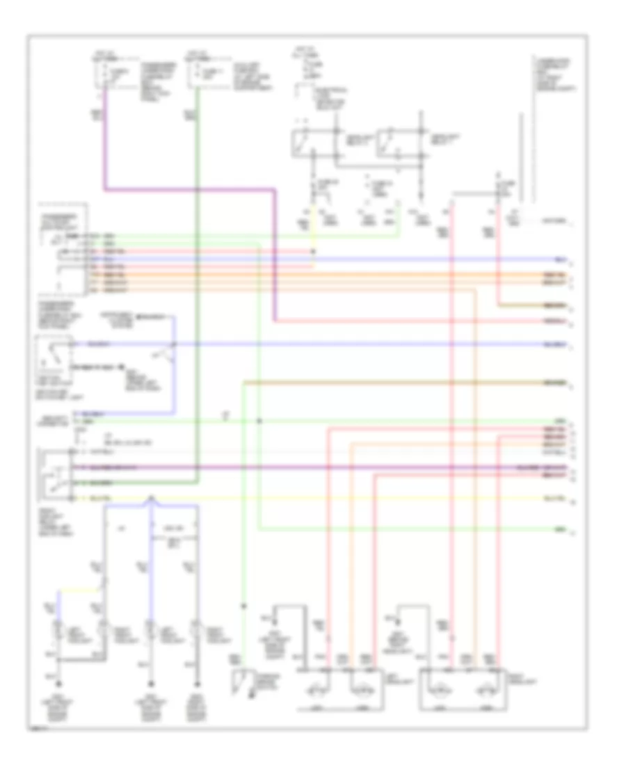
HEADLIGHTS
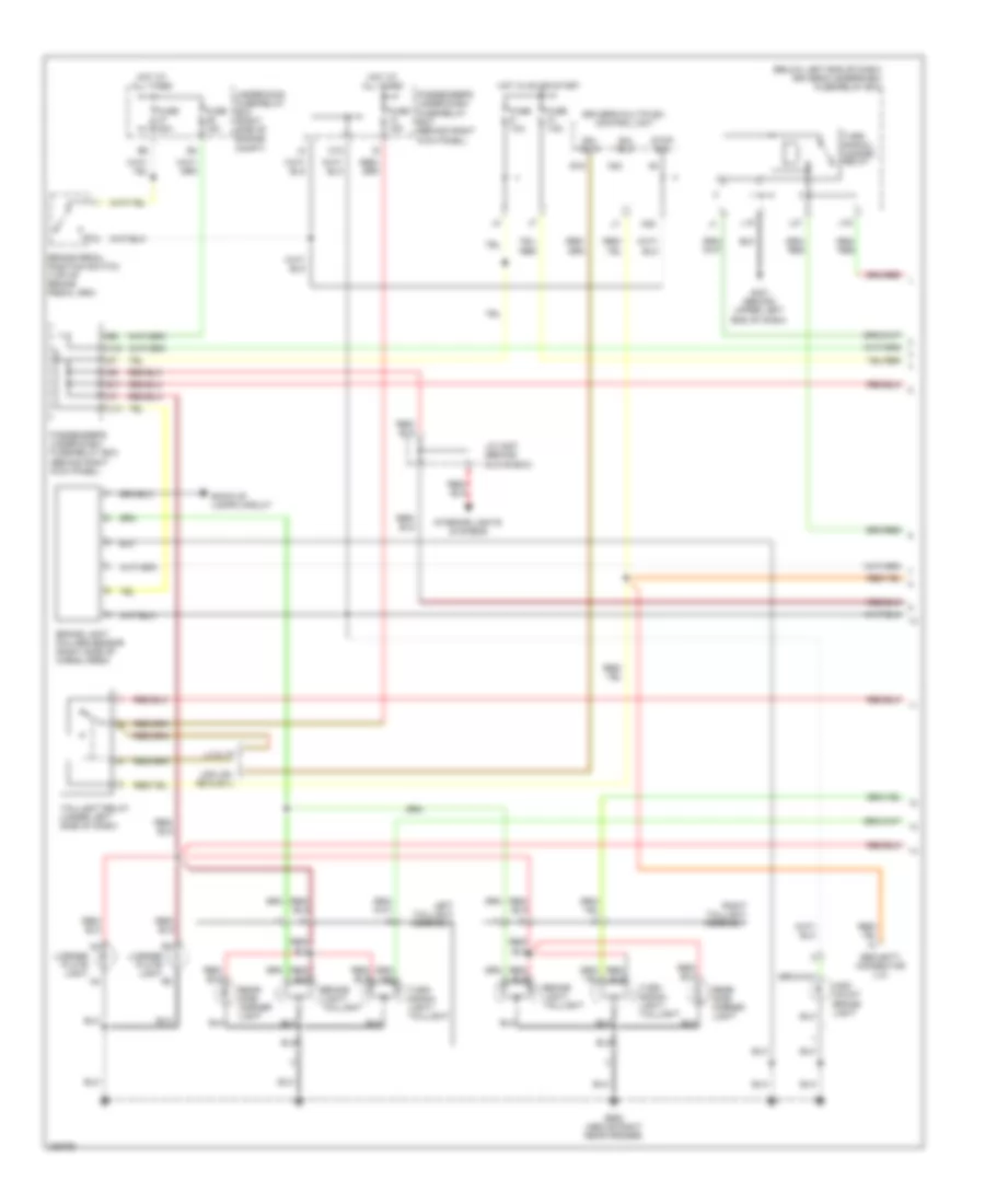
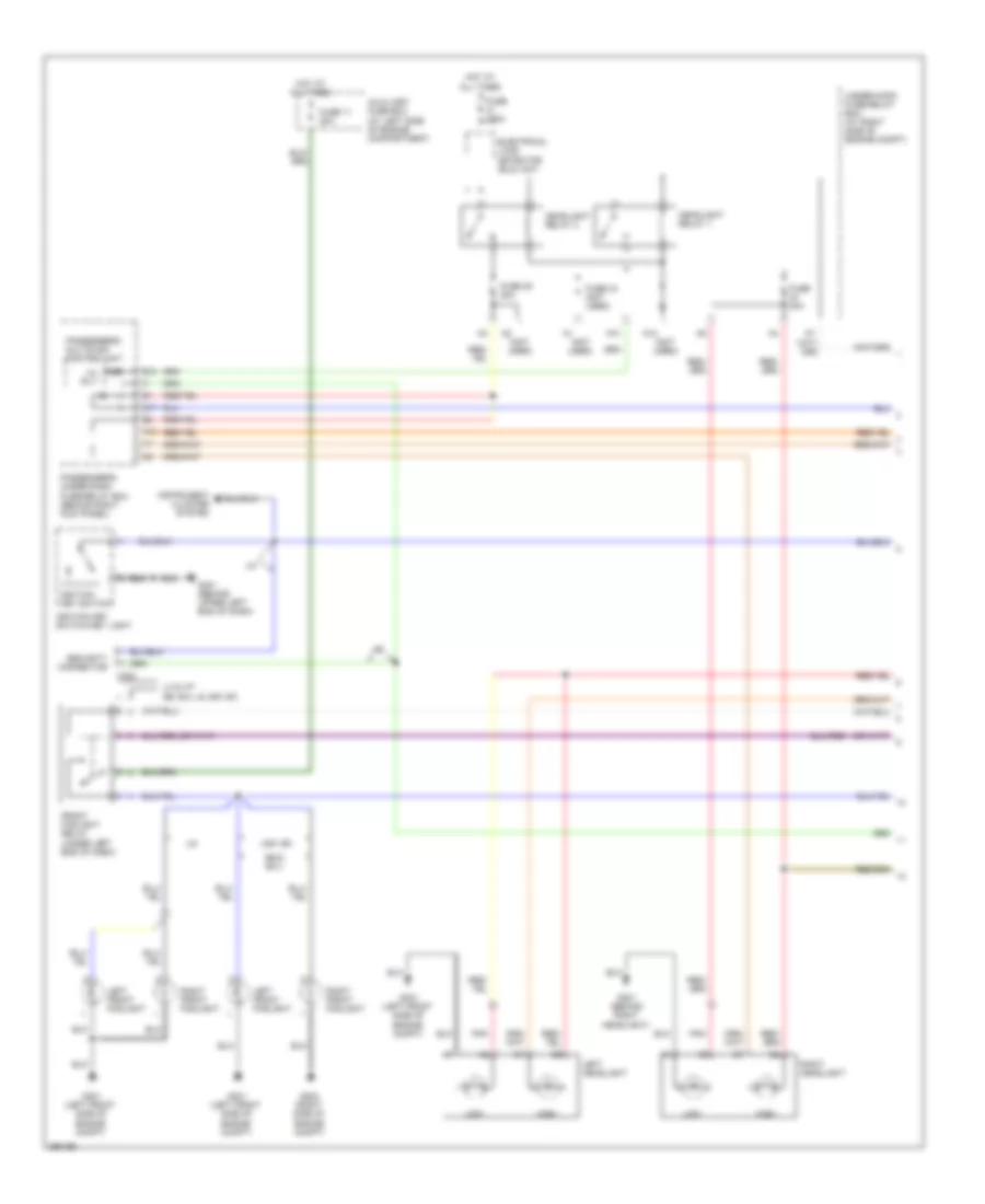
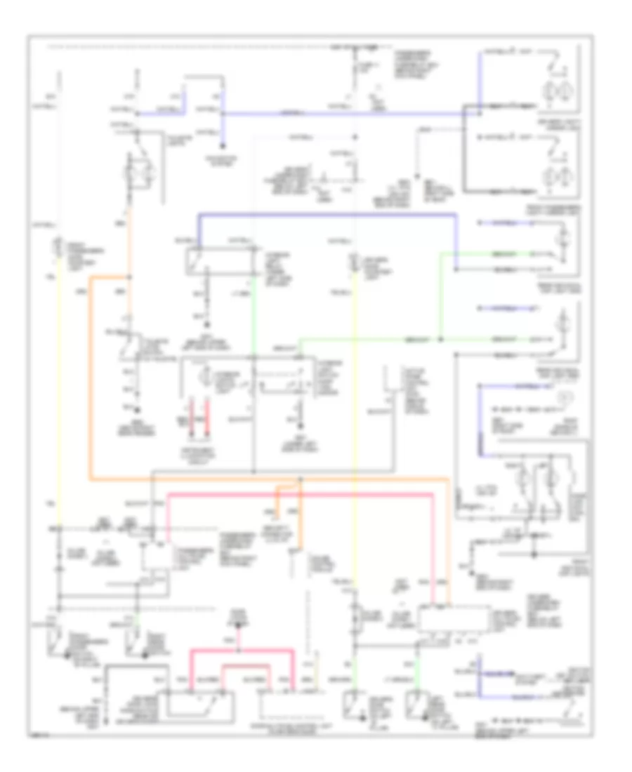
Headlights Wiring Diagram, with DRL (1 of 2) for Honda Pilot SE 2008
List of elements for Headlights Wiring Diagram, with DRL (1 of 2) for Honda Pilot SE 2008:
- (not used)
- A12
- A13
- A20 h/l rly-
- Auxiliary fuse box (at left side of engine compartment)
- B13
- C324
- Electrical load detector (eld) unit
- Front foglight relay (under left end of dash)
- Fuse 11 20a
- Fuse 120a
- Fuse 20a
- Fuse 44 (not used)
- Fuse 45 20a
- Fuse 6 10a
- G17
- G201 (behind right headlight)
- G202 (right side of engine compt)
- G301 (left front side of engine compt)
- G401 (behind upper left end of dash)
- H13
- Headlight relay 1
- Headlight relay 2
- High
- Hot at all times
- I11
- Ignition key switch
- Ignition key switch/key light
- Instrument cluster system
- Left front foglight
- Left headlight
- Low
- Parking brake switch
- Passenger's multiplex control unit
- Passenger's under-dash fuse/relay box (behind right kick panel)
- Passenger's under-dash fuse/relay box) (behind right kick panel)
- Pnk
- Right front foglight
- Right headlight
- Se & ex-l
- Se, ex-l & usa: ex
- Security connector
- Under-hood fuse/relay box (at right side of engine compt)
- Usa: ex
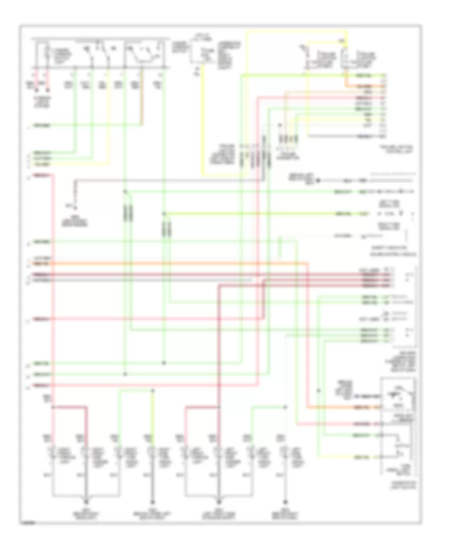
Headlights Wiring Diagram, with DRL (2 of 2) for Honda Pilot SE 2008
List of elements for Headlights Wiring Diagram, with DRL (2 of 2) for Honda Pilot SE 2008:
- (not used)
- A10 h/l rly+
- A14
- A15
- A16 dr sw
- A17
- A2 bus dr
- A20
- B19
- B26
- Bus
- Combination light switch
- D19
- Dim
- Dimmer relay (under left end of dash)
- Dimmer switch
- Door multiplex control unit (in driver's door)
- Driver's door lock knob switch (rear of driver's door)
- Driver's door switch (on left ``b" pillar)
- Driver's multiplex control unit
- Driver's under-dash fuse/relay box (below left end of dash)
- Drl control unit
- Drl ind
- Flash- to-pass switch
- Fog light ind
- Fog light switch
- Fuse 5 10a
- Fuse 9 10a
- G401 (behind upper left end of dash)
- G502 (behind left end of dash)
- Gauge control module
- Gnd
- H14
- Head
- Headlight switch
- High beam ind
- Hot in on
- Hot in on or start
- Igkey sw
- Interior lights system
- J18
- L12
- L14
- L15
- L20
- Off
- Park
- Pass b13
- Se, ex-l & usa: ex
- Sw a13
- Unlock
- Usa: ex se & ex-l
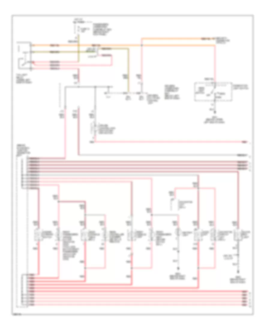
Headlights Wiring Diagram, without DRL (1 of 2) for Honda Pilot SE 2008
List of elements for Headlights Wiring Diagram, without DRL (1 of 2) for Honda Pilot SE 2008:
- (not used)
- A12
- A13
- A20 h/l rly-
- Auxiliary fuse box (at left side of engine compartment)
- B13
- C324
- Electrical load detector (eld) unit
- Front foglight relay (under left end of dash)
- Fuse 11 20a
- Fuse 120a
- Fuse 20a
- Fuse 44 (not used)
- Fuse 45 20a
- G17
- G201 (behind right headlight)
- G202 (right side of engine compt)
- G301 (left front side of engine compt)
- G401 (behind upper left end of dash)
- H13
- Headlight relay 1
- Headlight relay 2
- High
- Hot at all times
- I11
- Ignition key switch
- Ignition key switch/key light
- Instrument cluster system
- Left front foglight
- Left headlight
- Low
- Lx & vp
- Passenger's multiplex control unit
- Passenger's under-dash fuse/relay box (behind right kick panel)
- Pnk
- Right front foglight
- Right headlight
- Se & ex-l
- Se, ex-l & usa: ex
- Security connector
- Under-hood fuse/relay box (at right side of engine compt)
- Usa: ex;
Headlights Wiring Diagram, without DRL (2 of 2) for Honda Pilot SE 2008
List of elements for Headlights Wiring Diagram, without DRL (2 of 2) for Honda Pilot SE 2008:
- (below left end of dash) driver's under-dash fuse/relay box
- (not used)
- (or)
- A10 h/l rly+
- A14
- A15
- A16 dr sw
- A17
- A2 bus dr
- A20
- B19
- B26
- Bus
- Combination light switch
- D19
- Dimmer relay (under left end of dash)
- Dimmer switch
- Door multiplex control unit (in driver's door)
- Driver's door lock knob switch (rear of driver's door)
- Driver's door switch (on left ``b" pillar)
- Driver's multiplex control unit
- Flash- to-pass switch
- Fog light ind
- Fog light switch
- G401 (behind upper left end of dash)
- G502 (behind left end of dash)
- Gauge control module
- Gnd
- H14
- Head
- Headlight switch
- High beam ind
- Igkey sw
- Interior lights system
- J18
- L12
- L15
- L20
- Off
- Park
- Pass b13
- Se, ex-l & usa: ex
- Sw a13
- Unlock
- Usa: ex se & ex-l
HORN
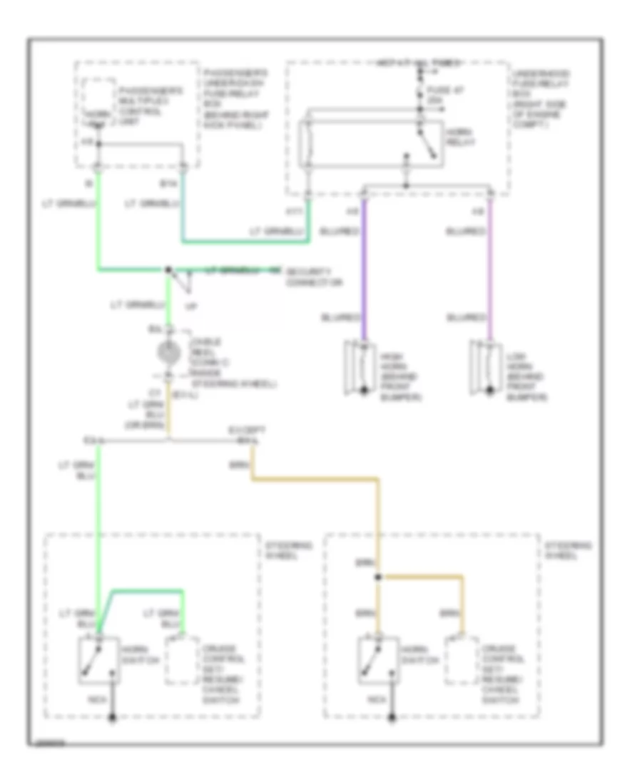
Horn Wiring Diagram for Honda Pilot SE 2008
List of elements for Horn Wiring Diagram for Honda Pilot SE 2008:
- (behind right kick panel)
- (ex-l)
- A11
- B14
- Cable reel (conn c: inside steering wheel)
- Cruise control set/ resume/ cancel switch
- Ex-l
- Except ex-l
- Fuse 47 20a
- High horn (behind front bumper)
- Horn relay
- Horn rly
- Horn switch
- Hot at all times
- Low horn (behind front bumper)
- Nca
- Passenger's multiplex control unit
- Passenger's under-dash fuse/relay box
- Security connector
- Steering wheel
- Underhood fuse/relay box (right side of engine compt)
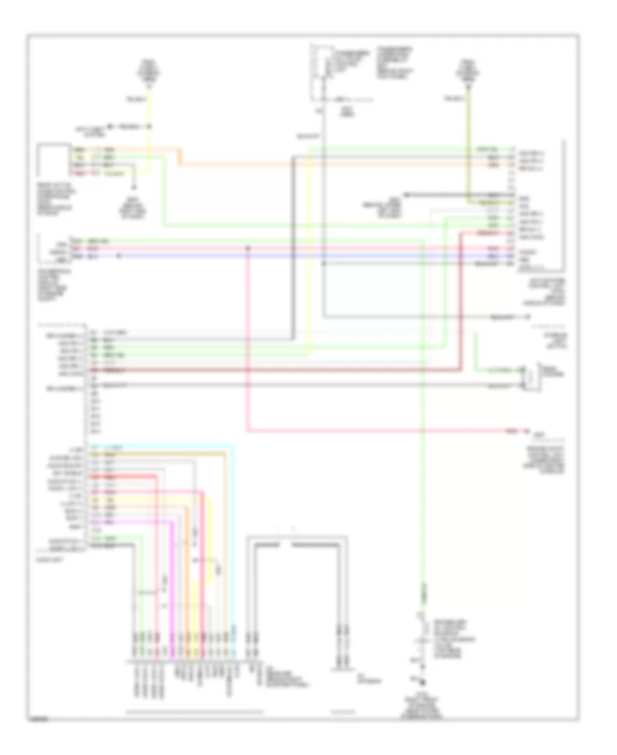
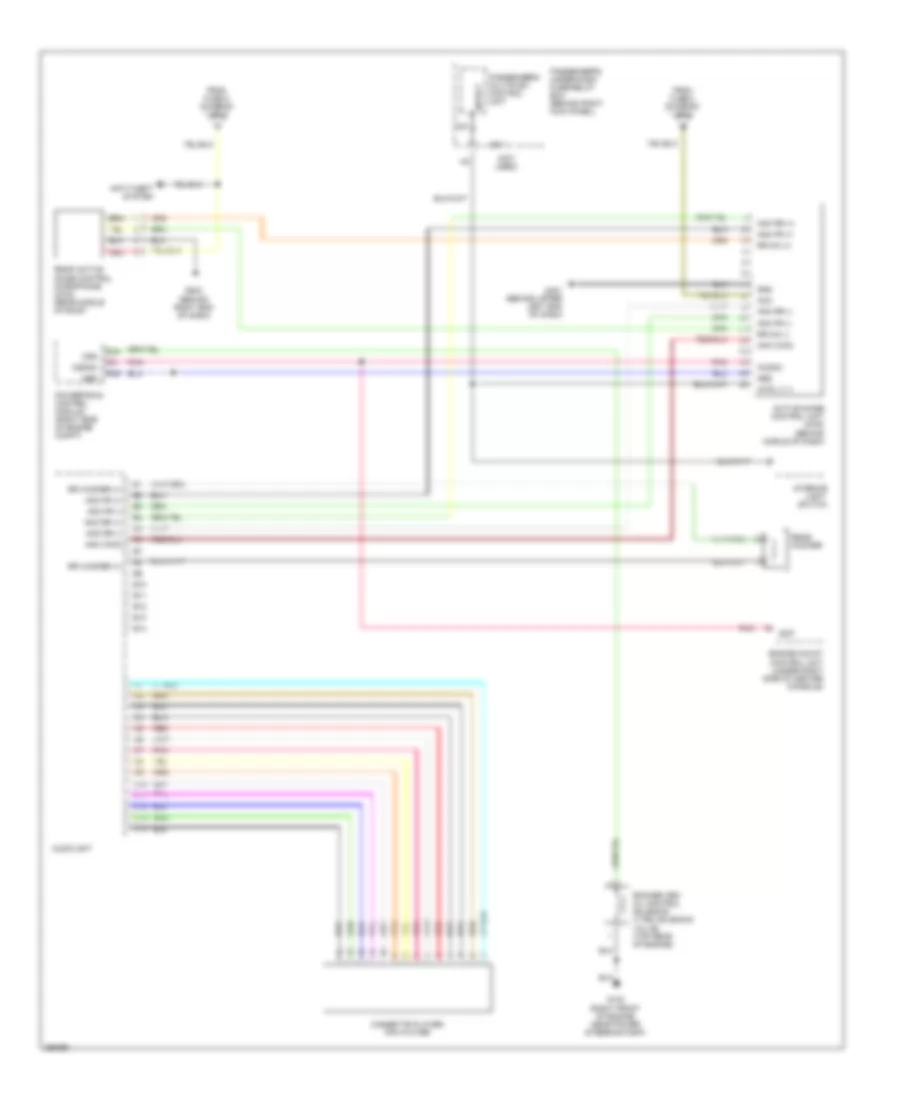
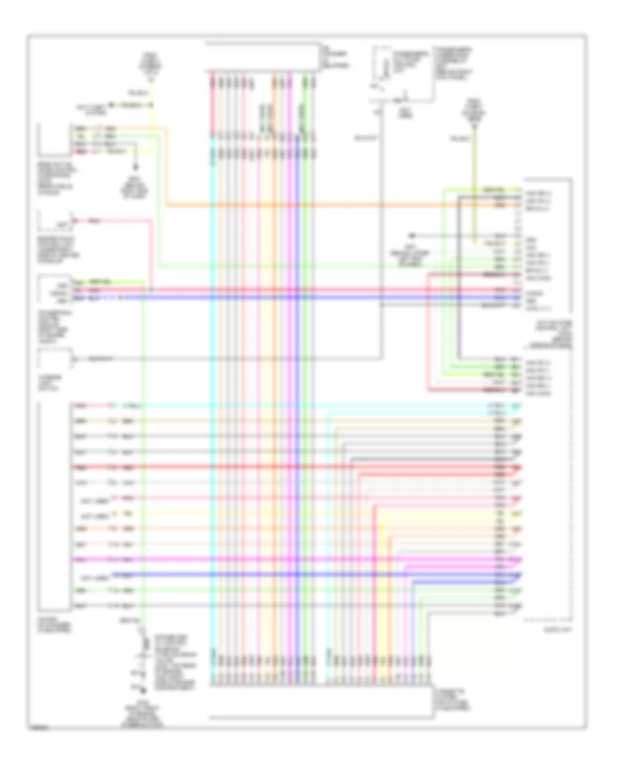
INSTRUMENT CLUSTER
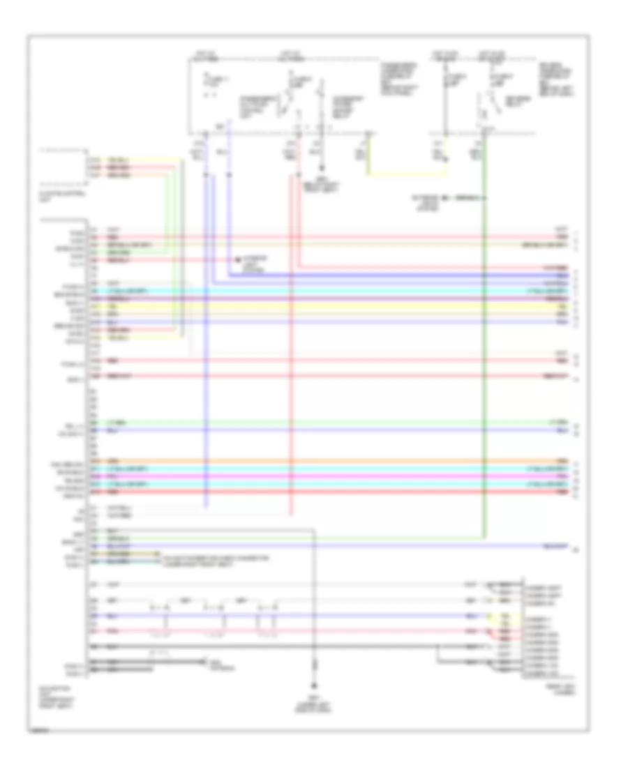
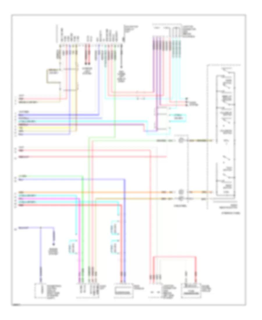
Instrument Cluster Wiring Diagram (1 of 2) for Honda Pilot SE 2008
List of elements for Instrument Cluster Wiring Diagram (1 of 2) for Honda Pilot SE 2008:
- (4wd)
- (on left "c" pillar) left rear door switch
- (usa: ex, se & ex-l)
- A/t temp ind
- A10
- A11
- A12
- A13
- A14
- A15
- A16
- A17
- A18
- A19
- A20
- Abs ind
- Air conditioning system exterior lights system
- Anti-theft system
- B10
- B11
- B12
- B13
- B14
- B15
- B16
- B17
- B18
- B19
- B20
- B21
- B22
- B23
- B24
- B25
- B26
- B27
- B28
- B29
- B30
- B31
- B32
- B33
- B34
- B35
- B36
- Brake lamp ind
- Brake system ind (usa)
- Canada only
- Charging system ind
- Compulsory turning-off circuit
- Compulsory turning-on circuit
- Computer data lines system
- Coolant temperature gauge
- Cruise control system
- Cruise control system air conditioning system
- D18
- Door locks & anti-theft systems
- Door locks system
- Drive circuit
- Driver's door switch (on left "b" pillar)
- Driver's under-dash fuse/relay box (below left end of dash)
- Exterior lights system
- Fail-safe circuit
- Fuel gauge
- Fuse 8 7.5a
- Fuse 9 10a
- G502 (behind left end of dash)
- Gauge contol module
- Headlight system
- Headlights system
- Hot in acc or on
- Hot in on or start
- Interior light system
- Low oil pressure ind
- Low tire pressure ind
- M11
- Maintenance required ind
- Mil ind
- Ods unit (in left side of front passenger's seat)
- Pnk
- Red
- Seat belt reminder ind
- Side airbag cut-off ind
- Speedometer
- Srs ind
- Tachometer
- Tire indicators
- To 10v stabilize circuit (diagram 2 of 2)
- To leds (diagram 2 of 2)
- To tail- gate ind (diagram 2 of 2)
- Tpms display circuit
- Tpms ind
- Transceiver f-can
- Transmissions system
- Trunk, tailgate, fuel doors system
- Vsa activation ind
- Vsa ind
- Vtm-4 ind
- Warning drive circuit
- Warnings system
- Washer fluid level ind
- Wiper/washer system
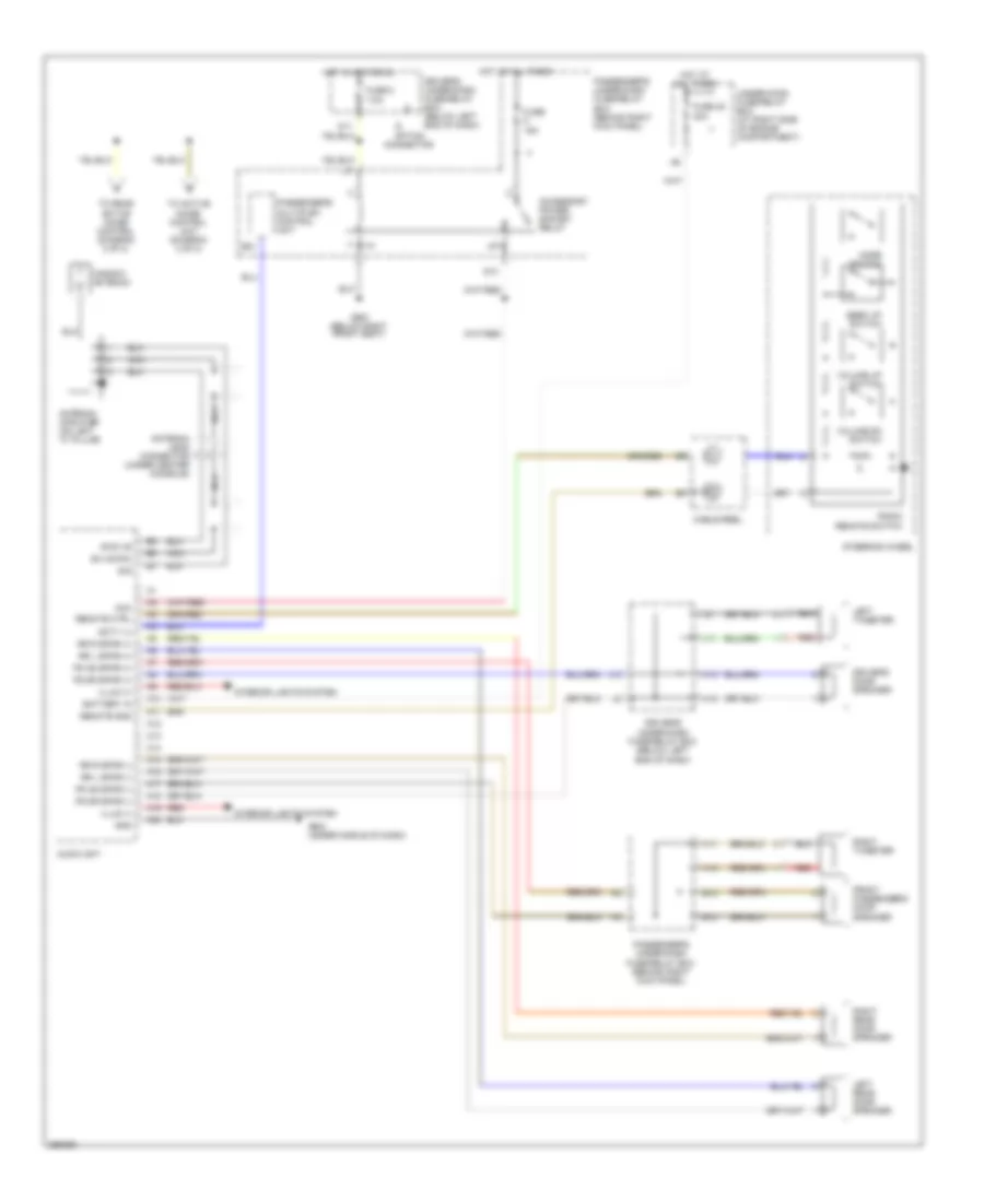
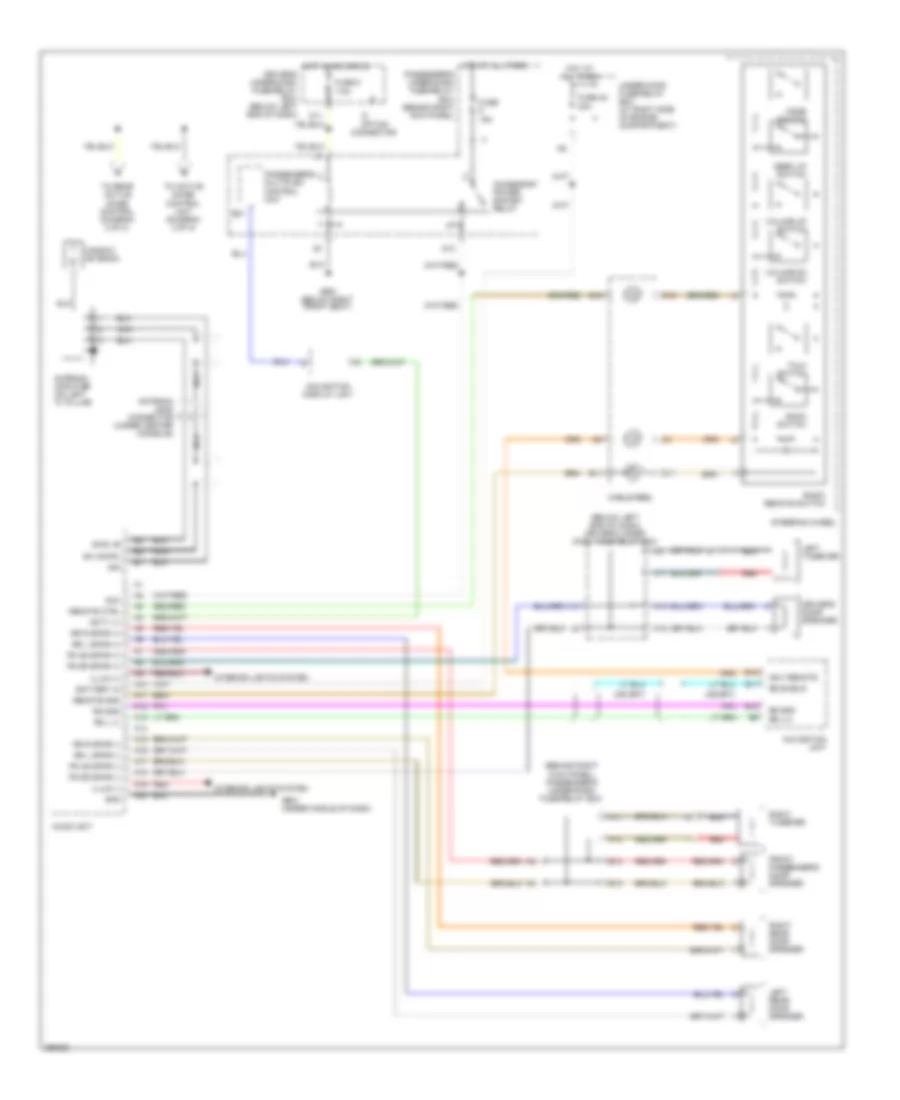
Instrument Cluster Wiring Diagram (2 of 2) for Honda Pilot SE 2008
List of elements for Instrument Cluster Wiring Diagram (2 of 2) for Honda Pilot SE 2008:
- (2wd)
- (canada)
- (diagram 1 of 2)
- (led)
- (left front side of engine compt)
- 10v stabilize circuit
- 5 v control
- A10
- A11
- A12
- A13
- A14
- A15
- A16
- A17
- A18
- A19
- A20
- Anti-theft system, transmissions system & headlights system (canada)
- B16
- B17
- B18
- B19
- B22
- B23
- B26
- B27
- B29
- B33
- B34
- B35
- B36
- Brake fluid level switch (integral to brake fluid reservoir cap)
- Buzzer
- C14
- C16
- Circuit
- Cruise control dimming circuit
- Cruise control ind
- Dial brightness control and dimming circuit
- Dim
- Dimming circuit
- Driver
- Driver seat belt buckle switch 1) unbuckled 2) buckled
- Driver's door ind
- Drl ind
- Eco ind
- Eco indicator
- F-can transceiver
- Fog light ind
- From brake lamp ind c (diagram 1 of 2)
- From side airbag cut-off ind a
- From srs ind b (diagram 1 of 2)
- Front passenger's door ind
- Front passenger's door switch (on right "b" pillar)
- Fuel gauge sending unit
- Fuel tank unit
- Fuse 13 7.5a
- G15
- G16
- G301
- G801 (below center console)
- Gauge control module
- H16
- High beam ind
- Hot at all times
- Immobilizer system ind
- J/c c306 (behind left side of dash)
- K-line transceiver
- Lcd
- Lcd brightness control and dimming circuit
- Left rear door ind
- Left turn signal ind
- Lights on ind
- Oil pressure switch (on lower right front of engine)
- On/off 5v
- Parking brake switch (on top of parking brake pedal)
- Passenger's under-dash fuse/relay box (behind right kick panel)
- Pointer brightness control and dimming circuit
- Right rear door ind
- Right rear door switch
- Right turn signal ind
- Tailgate ind
INTERIOR LIGHTS
Courtesy Lamps Wiring Diagram for Honda Pilot SE 2008
List of elements for Courtesy Lamps Wiring Diagram for Honda Pilot SE 2008:
- (behind upper left end of dash) g401
- (not
- (not used)
- 0=off 1=on 2=door
- A13
- A14
- A15
- A16
- A17
- A21
- Active noise control unit (2wd) (behind middle of dash)
- Anti-theft system
- B16
- C10
- C14
- C15
- C16
- C19
- D3 (not
- Door locks system
- Door multiplex control unit (in driver's door)
- Driver's door courtesy light
- Driver's door lock knob switch (rear of driver's door)
- Driver's door switch (on left ``b" pillar)
- Driver's multiplex control unit
- Driver's under-dash fuse/relay box (below left end of dash)
- Driver's vanity mirror light
- E10
- F12
- Front individual map lights
- Front passenger's door courtesy light
- Front passenger's door switch (on right ``b" pillar)
- Front passenger's vanity mirror light
- Fuse 11 10a
- G401 (behind upper left end of dash)
- G501 (under left side of dash)
- G503 (behind right end of dash)
- G503 (lx, vp & usa; ex) (behind right end of dash)
- G652 (above right rear fender)
- G901 (right side of roof)
- G901 (se & ex-l) (right side of roof)
- Gauge control module
- H10
- H14
- H18
- Home link unit (usa; ex)
- Hot at all times
- Ignition key switch
- Ignition key switch/ key light
- In-line diode 1
- In-line diode 2
- In-line diode 3 (not used)
- In-line diode 4
- Instrument illumination circuit
- Interior light relay (under left side of dash)
- Interior light switch
- Interior lights switch light
- Left
- Left rear door switch (on left ``c" pillar)
- Lx, vp & usa: ex
- Lx, vp usa; ex
- Navigation system
- Passenger's multiplex control unit
- Passenger's under-dash fuse/relay box (behind right kick panel)
- Pnk
- Rear individual map light (2nd)
- Rear individual map light (3rd)
- Red
- Right
- Right rear door switch
- Roof console (se & ex-l)
- Se & ex-l
- Se; ex-l
- Security connector (lx & vp)
- Tailgate latch switch (in tailgate)
- Tailgate lights
- Used)
Instrument Illumination Wiring Diagram (1 of 2) for Honda Pilot SE 2008
List of elements for Instrument Illumination Wiring Diagram (1 of 2) for Honda Pilot SE 2008:
- (behind glove box) junction connector c207
- A19
- A22
- Ashtray light
- Audio unit
- B16
- Combination light switch
- Connector (vp & lx)
- Cruise control main switch/vsa off switch
- Driver's multiplex control unit
- Driver's under-dash fuse/relay box (below left end of dash)
- Front console light
- Front passenger's air bag cut-off indicator (2wd) vtm-4 lock switch/front passengers air cut-off indicator (4wd)
- Front passenger's seat heater switch (ex-l)
- Fuse 10 15a
- G401 (behind upper left end of dash)
- G503 (behind right end of dash)
- Glove box light
- Hazard warning switch
- Head
- Head light switch
- Hot at all times
- Ill+
- J13
- K16
- Lx & vp
- Navigation display unit (ex-l)
- Navigation unit (ex-l)
- Off
- Park
- Passenger's under-dash fuse/relay box (behind right kick panel)
- Rear controller & screen (se, ex-l & res dvd)
- Red
- Roof console (se & ex-l)
- Security
- Sml rly+
- Sml rly-
- Taillight relay (under left side of dash)
- Usa: ex, lx & vp
- Usa; ex, se & ex-l
Instrument Illumination Wiring Diagram (2 of 2) for Honda Pilot SE 2008
List of elements for Instrument Illumination Wiring Diagram (2 of 2) for Honda Pilot SE 2008:
- (led)
- A10
- A13
- Auxiliary jack assembly (se, ex-l & res dvd)
- B14
- B17
- B18
- B23
- B25
- B26
- B30
- B36
- Climate control unit
- Dial brightness controller and dimming circuit
- Driver's door lock switch (usa; ex, se & ex-l)
- Driver's seat heater switch (ex-l)
- Driver's under-dash fuse/relay box (below left end of dash)
- Dvd player unit (se, ex-l & res dvd)
- Exterior lights system
- Front passenger's door lock switch (usa; ex, se & ex-l)
- Fuse 9 10a
- G502 (behind left end of dash)
- Gauge assembly
- Heater control panel
- Hot in on or start
- Interior light switch
- J16
- Lcd brightness controller and dimming circuit
- Lx & vp
- Moonroof switch (se & ex-l)
- Passenger's under-dash fuse/relay box (behind right kick panel)
- Pointer brightness controller and dimming circuit
- Power mirror switch
- Rear heater- a/c control unit
- Red
- Se & ex-l
- Usa; ex
NAVIGATION
Compass Wiring Diagram for Honda Pilot SE 2008
List of elements for Compass Wiring Diagram for Honda Pilot SE 2008:
- Driver's underdash fuse/relay box (below left end of dash)
- Electrical compass unit
- Fuse 7.5a
- G901 (right side of roof)
- Hot in on or start
Navigation Wiring Diagram (1 of 2) for Honda Pilot SE 2008
List of elements for Navigation Wiring Diagram (1 of 2) for Honda Pilot SE 2008:
- (under left side of dash)
- A10
- A11
- A12
- A13
- A14
- A15
- A16
- A17
- A18
- A19
- A20
- Ac-clk
- Ac-si
- Ac-so
- Acc
- Accessory power socket relay
- B sig
- B10
- B11
- B12
- B13
- B14
- B21
- Back lt
- Bus (+)
- Bus (-)
- Bus shield
- C sig
- C19
- Camera adpt
- Camera gnd
- Camera sh
- Camera v
- Camera vcc
- Climate control unit
- Diag (+)
- Diag (-)
- Driver's under-dash fuse/relay box (behind left end of dash)
- Exterior lights system
- F-can hi
- F-can lo
- Fuse 11 10a
- Fuse 8 7.5a
- Fuse 9 10a
- Fuse 9 15a
- G sig
- G13
- G501
- G651 (below right front seat)
- Gnd
- Gnd mic
- Gps antenna
- Ground sig
- Hot at all times
- Hot in on or acc
- Hot in on or start
- Ill (+)
- Interior light system
- M11
- Mic shield
- Mic sig (+)
- Navi rem sw
- Navigation service check connector (under right front seat)
- Navigation unit (under right front seat)
- Nca
- Passenger's multiplex control unit
- Passenger's under-dash fuse/relay box (behind right kick panel)
- Pnk
- R sig
- Rear view camera
- Red
- Reverse relay
- Rg gnd
- Rg l (+)
- Rg shield
- Shield sig
- Vsp
Navigation Wiring Diagram (2 of 2) for Honda Pilot SE 2008
List of elements for Navigation Wiring Diagram (2 of 2) for Honda Pilot SE 2008:
- A11
- A12
- A13
- A29
- Acc
- Audio system
- Audio unit
- B sig
- B11
- B12
- Back switch
- Bus (+)
- Bus sh gnd
- C sig
- C11
- C12
- Cable reel
- Ecu bus (-)
- Engine control system
- F-can transceiver
- G sig
- G501 (under left side of dash)
- Gauge control module
- Gnd
- Gnd sig
- Ill (+)
- Ill (-)
- Interior light system
- Junction connector c208 (behind glove box)
- Junction connector c306 (behind left side of dash)
- Microphone
- Mode switch
- Navi scty
- Navigation display unit
- Powertrain control module (right side of engine compt)
- R sig
- Radio remote switch
- Red
- Rem ctrl
- Rem gnd
- Rg gnd
- Rg l (+)
- Roof console
- Scty (+)
- Security
- Seek up switch
- Sig 1 sh gnd
- Steering wheel
- Talk switch
- Volume dn switch
- Volume up switch
- Vssout
Parking Assistant Wiring Diagram for Honda Pilot SE 2008
List of elements for Parking Assistant Wiring Diagram for Honda Pilot SE 2008:
- Backup sensor beeper assembly (right side of cargo area)
- Backup sensor beeper switch
- Backup sensor control unit (right side of cargo area)
- Backup sensor in-line fuse (right rear of cargo area)
- Brake light failure sensor (right rear of cargo area)
- Brake light failure sensor connector (at right side of cargo area)
- Driver's underdash fuse/relay box (below left end of dash)
- Exterior lights system
- Fuse 9 10a
- G652 (above right rear fender)
- Hot in on or start
- Left corner backup sensor (left corner of rear bumper)
- Left middle backup sensor (left side of rear bumper)
- On indicator
- Red
- Reverse relay
- Right corner backup sensor (right corner of rear bumper)
- Right middle backup sensor (right side of rear bumper)
- Trailer lighting connector (at left side of cargo area)
POWER DISTRIBUTION
Power Distribution Wiring Diagram (1 of 4) for Honda Pilot SE 2008
List of elements for Power Distribution Wiring Diagram (1 of 4) for Honda Pilot SE 2008:
- (behind right kick panel) passenger's under-dash fuse/relay box
- (not used)
- (option connector)
- (right side of engine compartment) under-hood fuse/relay box
- A/c compressor clutch relay
- A/c condenser fan relay
- A12
- A17
- Acc
- Alternator
- Battery
- D10
- Data link connector (dlc)
- Door multiplex control unit
- Driver's power seat adjustment switch (usa: ex, ex-l & se)
- Driver's under-dash fuse/relay box (below left end of dash)
- Drl control unit (canada)
- E16
- Electrical load detector (eld) unit
- Ex-l & se
- Front blower motor relay
- Front passenger's power window switch
- Fuse 1 20a
- Fuse 14 7.5a
- Fuse 15 20a
- Fuse 16 20a
- Fuse 2 20a
- Fuse 3 20a
- Fuse 4 20a
- Fuse 41 120a
- Fuse 42 50a
- Fuse 46 15a
- Fuse 5 (not used)
- Fuse 51 40a
- Fuse 52 40a
- Fuse 53 30a
- Fuse 55 30a
- Fuse 56 40a
- Fuse 57 30a
- Fuse 58 30a
- Fuse 59 7.5a
- Fuse 6 10a
- Fuse 7 20a
- Fuse 8 20a
- G10
- G18
- G651 (below right front seat)
- H18
- I10
- Ignition switch
- Left rear power window switch
- Lock
- Moonroof close relay
- Moonroof open relay
- P/w main rly
- Passenger's multiplex control unit
- Pgm-fi main relay 1
- Power window control unit
- Power window relay
- Radiator fan relay
- Rear blower motor relay
- Rear window defogger relay
- Red
- Right rear power window switch
- Run
- Seat heater relay (ex-l)
- Start
- Starter
- Starter solenoid
- T101
- To auxiliary fuse box (diagram 4 of 4)
- To fuse 4 (diagram 2 of 4)
- To fuse 47 (diagram 3 of 4)
- To fuse 54 (diagram 3 of 4)
- To fuse 6 (diagram 2 of 4)
- To fuse 8 (diagram 4 of 4)
- To starter cut relay (diagram 4 of 4)
Power Distribution Wiring Diagram (2 of 4) for Honda Pilot SE 2008
List of elements for Power Distribution Wiring Diagram (2 of 4) for Honda Pilot SE 2008:
- (below left end of dash) driver's under-dash fuse/relay box
- (ex, ex-l)
- (ex-l)
- (not used)
- (right front of engine compt)
- (vp)
- A/c compressor clutch relay
- A/c condenser fan relay
- A/c diode assembly
- A/c diode b
- Ac inverter unit (res (dvd): se & ex-l)
- Alternator
- Auxiliary under-hood relay box
- Auxiliary under-hood relay box (right front of engine compt)
- B11
- B13
- Brake pedal position switch
- C17
- C555 option connector
- Climate control unit (usa: ex, ex-l & se)
- Cruise control main switch/vsa off switch
- D11
- D13
- D16
- Drl control unit (canada)
- Electrical compass unit (ex-l w/o navigation)
- Evap canister purge valve
- Fan control relay
- From ignition switch (diagram 1 of 4)
- Front blower motor relay
- Front passenger's airbag cut-off indicator (2wd)
- Front passenger's airbag cut-off indicator/ vtm-4 lock switch (4wd)
- Front washer motor relay
- Fuse 10 7.5a
- Fuse 11 7.5a
- Fuse 12 30a
- Fuse 3 7.5a
- Fuse 4 7.5a
- Fuse 5 10a
- Fuse 6 15a
- Fuse 7 7.5a
- H17
- Hazard warning switch
- Heater control panel (vp)
- Intermittent wiper relay
- J10
- J12
- J15
- Junction connector c104 (rear of engine compt)
- L14
- M13
- M14
- M15
- Ods unit
- Option connector
- Passenger's under-dash fuse/relay box
- Passenger's under-dash fuse/relay box (behind right kick panel)
- Power mirror switch
- Powertrain control module
- Rear blower motor relay
- Rear mode control motor (ex, ex-l, vp & se)
- Rear washer motor relay
- Rear window defogger relay
- Rear window intermittent wiper relay
- Rear window wiper motor
- Recirculation control motor
- Seat heater relay
- To fuse 1 (diagram 4 of 4)
- Under-hood fuse/relay box (right side of engine compt)
- Vsa modulator control unit
- Vtm-4 control unit (4wd)
- Vtm-4 relay (4wd)
- Wind- shield wiper motor
- Wiper/ washer switch
- Wiper/washer switch
Power Distribution Wiring Diagram (3 of 4) for Honda Pilot SE 2008
List of elements for Power Distribution Wiring Diagram (3 of 4) for Honda Pilot SE 2008:
- (behind right kick panel) passenger's under-dash fuse/relay box
- (below left end of dash) driver's under-dash fuse/relay box
- (not used)
- (w/ rear entertainment system (ex-l) & se)
- +b clock
- +b d/l
- A10
- A12
- A23
- A24
- Accessory power socket relay
- Audio unit
- B15
- B24
- Brake pedal position switch
- C10
- C19
- C324 security connector (vp)
- Cigarette lighter (accessory installed)
- Cigarette lighter connector (optional)
- Console accessory power socket
- Door multiplex control unit
- Driver's door courtesy light
- Driver's multiplex control unit
- Driver's vanity mirror light
- Dvd player unit
- E10
- Ex-l
- F12
- From fuse 41 & battery (diagram 1 of 4)
- From fuse 59 (diagram 1 of 4)
- Front accessory power socket
- Front individual map lights
- Front passenger's door courtesy light
- Front passenger's vanity mirror light
- Fuse 10 15a
- Fuse 11 10a
- Fuse 12 20a
- Fuse 13 7.5a
- Fuse 47 20a
- Fuse 48 20a
- Fuse 49 15a
- Fuse 50 20a
- Fuse 54 40a
- Fuse 9 15a
- G11
- G13
- G15
- G16
- G503 (behind right end of dash)
- G651 (below right front seat)
- Gauge control module
- H15
- H18
- Hazard warning switch
- Headlight relay 1
- Headlight relay 2
- Horn relay
- I12
- I16
- Ignition key light
- Ignition key switch/key light
- Immobilizer control unit- receiver
- Imoes unit
- Interior light relay
- Interior lights system
- J11
- Keyless receiver unit
- M19
- Navi- gation unit
- Navigation display unit
- Navigation display unit (ex-l)
- Navigation unit (ex-l)
- Passenger's multiplex control unit
- Passenger's under-dash fuse/relay box (behind right kick panel)
- Rear controller & screen
- Rear individual map lights (2nd)
- Rear individual map lights (3rd)
- Roof console (ex-l & se)
- Security indicator (usa: ex, ex-l & se)
- Tailgate lights
- Taillight relay
- To fuse 8 (diagram 4 of 4)
- Trailer lighting connector
- Under-hood fuse/relay box (right side of engine compartment)
- Vbu
- W/ rear entertainment system ex-l & se
Power Distribution Wiring Diagram (4 of 4) for Honda Pilot SE 2008
List of elements for Power Distribution Wiring Diagram (4 of 4) for Honda Pilot SE 2008:
- (below left end of dash) driver's under-dash fuse/relay box
- (left side of engine compt) auxiliary fuse box
- (not used)
- A/f sensor relay
- A17
- A18
- A22
- A24
- Ac inverter unit (w/ rear
- Acm control relay (2wd)
- Acm ctrl relay (2wd)
- Active noise control unit (2wd)
- B25
- B29
- B37
- Brake light failure sensor
- C13
- C320 fog light connector
- C324 security connector (vp)
- Canada
- Cargo area accessory power socket
- Driver's multiplex control unit
- Engine mount control unit (2wd)
- Entertainment
- Etcs control relay
- From accessory power socket relay (diagram 3 of 4)
- From ignition switch (diagram 1 of 4)
- From pin a5 of driver's under-dash h
- From under-hood fuse/relay box (diagram 1 of 4)
- Front fog light relay
- Fuse 1 15a
- Fuse 1 20a
- Fuse 10 7.5a
- Fuse 11 20a
- Fuse 2 10a
- Fuse 2 40a
- Fuse 3 30a
- Fuse 4 20a
- Fuse 5 10a
- Fuse 6 15a
- Fuse 7 15a
- Fuse 8 15a
- Fuse 8 7.5a
- Fuse 9 10a
- Fuse 9 15a
- Fuse/relay box (diagram 2 of 4)
- G401 (behind upper left end of dash)
- G501 (under left side of dash)
- G602 (left side of cargo area)
- Gauge control module
- Ig1 meter
- Ignition coil relay
- Immobilizer control unit- receiver
- Imoes unit
- Keyless entry connector
- Keyless receiver unit
- M11
- Option connector
- Park pin relay
- Passenger's multiplex control unit
- Passenger's under-dash fuse/relay box
- Passenger's under-dash fuse/relay box (behind right kick panel)
- Pgm-fi main relay 2
- Powertrain control module
- Rear accessory power socket (vp, ex, ex-l navigation, ex-l)
- Rear accessory power socket relay (under left side of dash)
- Rear active noise control microphone (2wd)
- Red
- Reverse relay
- Shift lock relay
- Shift lock solenoid
- Srs unit
- Starter cut relay
- System ex-l & se)
- Tpms control unit
- Usa: ex, ex-l & se
- Vsa modulator control unit
- Vtm-4 lock switch/front passenger's airbag cut-off indicator (4wd)
- Vtm-4 relay (4wd)
POWER DOOR LOCKS
Power Door Locks Wiring Diagram, EX, EX-L, SE (1 of 2) for Honda Pilot SE 2008
List of elements for Power Door Locks Wiring Diagram, EX, EX-L, SE (1 of 2) for Honda Pilot SE 2008:
- (below right front seat) g651
- (not used)
- +b clock
- +b d/l
- A10
- A11
- A12
- A13
- A14
- A15
- A16
- A17
- A21
- A22
- A23
- A24
- Antenna
- B11
- B14
- B21
- B22
- Bus (door/dr)
- Bus as
- Bus dr
- C14
- C16
- C20
- D/l lock
- D/l unlck dr
- D/l unlock
- Door lock
- Door unlock
- Dr sw as
- Dr sw dr
- Dr sw ra
- Dr sw rd
- Driver's multiplex control unit
- Driver's under-dash fuse/relay box (below left end of dash)
- E10
- E15
- E17
- Front passenger's door lock actuator (rear of front passenger's door)
- Fuse 12 20a
- Fuse 13 7.5a
- G15
- G201 (behind right headlight)
- G401 (behind upper left end of dash)
- G501
- G503 (behind right end of dash)
- G601 (below left front seat)
- G651 (below right front seat)
- G652 (above right rear fender)
- Gnd
- H/l rly+
- H14
- Headlights system
- Hood sw
- Horn rly
- Horns system
- Hot at all times
- I12
- I14
- Ig key sw
- Ig1
- Ig1 meter
- Ignition key switch
- Ignition key switch/ key light
- Instrument cluster system
- Interior lights system
- Intrlt
- K/c as lock
- K/c as unlock
- K/l lock
- K/l panic
- K/l unlock
- Keyless receiver unit (behind right side of glove box)
- Left rear door lock knob switch (rear of left rear door)
- M19
- Nca
- Panic
- Passenger's multiplex control unit
- Passenger's under-dash fuse/relay box (behind right kick panel)
- Pnk
- Radio sw
- Rem as lock
- Rem as unlock
- Right rear door lock knob switch
- Scty in
- Security hood switch (center front of engine compt)
- Sgnd
- Sil as unlock
- Sil ra unlock
- Sil rd unlock
- Sound systems
- T/g sw
- Tailgate latch switch (in tailgate)
- Tailgate lights
Power Door Locks Wiring Diagram, EX, EX-L, SE (2 of 2) for Honda Pilot SE 2008
List of elements for Power Door Locks Wiring Diagram, EX, EX-L, SE (2 of 2) for Honda Pilot SE 2008:
- A12
- A15
- A16
- A17
- A18
- B30
- Door multiplex control unit (in driver's door)
- Driver's door key cylinder switch (in driver's door)
- Driver's door lock actuator (rear of driver's door)
- Driver's door lock knob switch (rear of driver's door)
- Driver's door lock switch
- Driver's door switch (on left ``b" pillar)
- Driver's underdash fuse/relay box (below left end of dash)
- Front passenger's door lock knob switch
- Front passenger's door lock switch
- Front passenger's door switch (on right ``b" pillar)
- Fuse 9 10a
- G401 (behind upper left end of dash)
- Gauge control module
- H16
- Hot in on or start
- Interior lights system
- K13
- L13
- Left rear door lock actuator (rear of left rear door)
- Left rear door switch (on left ``c" pillar)
- Lock
- Mpx-dr
- Pnk
- Red
- Right rear door lock actuator (rear of right rear door)
- Right rear door switch
- Security indicator
- Tailgate lock actuator (near center of tailgate)
- Unlock
- Vbu
Power Door Locks Wiring Diagram, VP (1 of 2) for Honda Pilot SE 2008
List of elements for Power Door Locks Wiring Diagram, VP (1 of 2) for Honda Pilot SE 2008:
- (behind right end of dash) g503
- (not used)
- (rear of driver's door) driver's door lock actuator
- +b clock
- +b d/l
- A10
- A11
- A12
- A13
- A14
- A15
- A16
- A17
- A21
- A22
- A23
- A24
- Antenna
- B11
- B14
- B16
- B17
- B22
- B30
- B34
- Bus (door/dr)
- Bus as
- Bus dr
- C14
- C16
- C20
- D/l lock
- D/l unlk dr
- D/l unlock
- Door lock
- Door unlock
- Dr sw as
- Dr sw ra
- Dr sw rd
- Driver's door switch (on left ``b" pillar)
- Driver's multiplex control unit
- Driver's under-dash fuse/relay box (below left end of dash)
- E10
- E15
- E17
- Front passenger's door switch
- Fuse 12 20a
- Fuse 13 7.5a
- Fuse 9 10a
- G501
- G503 (behind right end of dash)
- G651 (below right front seat)
- Gauge control module
- Gnd
- H/l rly+
- H14
- H16
- Headlights system
- Horn rly
- Horns system
- Hot at all times
- Hot in on or start
- I14
- Ig key sw
- Ig1
- Ig1 meter
- Interior lights system
- Intrlt
- K/c as lock
- K/c as unlock
- K/l lock
- K/l panic
- K/l unlock
- K13
- Keyless receiver unit (behind right side of glove box)
- L13
- Left rear door switch (on left "c" pillar)
- M19
- Nca
- Panic
- Passenger's multiplex control unit
- Passenger's under-dash fuse/relay box (behind right kick panel)
- Pnk
- Rem as
- Rem as lock
- Right rear door switch
- Sgnd
- Sml rly
- T/g sw
Power Door Locks Wiring Diagram, VP (2 of 2) for Honda Pilot SE 2008
List of elements for Power Door Locks Wiring Diagram, VP (2 of 2) for Honda Pilot SE 2008:
- (behind upper
- A12
- A15
- A16
- A17
- A18
- Bus
- C324
- C710
- Dash)
- Door multiplex control unit (in driver's door)
- Driver's door key cylinder switch (in driver's door)
- Driver's door lock knob switch (rear of driver's door)
- Driver's door lock switch
- Front passenger's door lock actuator (rear of front passenger's door)
- Front passenger's door lock switch
- G401
- G401 (behind upper left end of dash)
- G651 (below right front seat)
- G652 (above right rear fender)
- Headlights
- Ignition
- Ignition key switch/ key light
- Key
- Left end of
- Left rear door lock actuator (rear of left rear door)
- Lock
- Pnk
- Right rear door lock actuator (rear of right rear door)
- Security connector
- Switch
- System
- Tailgate latch switch (in tailgate)
- Tailgate lights
- Tailgate lock actuator (near center of tailgate)
- Unlk
- Unlock
- Vbu
POWER MIRRORS
Automatic Day/Night Mirror Wiring Diagram for Honda Pilot SE 2008
List of elements for Automatic Day/Night Mirror Wiring Diagram for Honda Pilot SE 2008:
- (not
- A/t gear position indicator
- A16
- A18
- Atpr
- Automatic dimming inside mirror
- C30
- D10
- Driver's underdash fuse/relay box (below left end of dash)
- Ex-l
- Fuse 10a
- Fuse 7.5a
- G101 (rear of engine)
- G503 (behind right end of dash)
- G901 (right side of roof)
- Gauge control module
- Hot in on or start
- Junction connector c104 (rear of engine compt)
- Junction connector c105 (top of transmission)
- K11
- Lx, vp, usa: ex
- Option connector (under roof console)
- Powertrain control (pcm) module (right side of engine compartment)
- Reverse relay
- Transmission range switch (on transmission end cover)
- Used)
Power Mirrors Wiring Diagram for Honda Pilot SE 2008
List of elements for Power Mirrors Wiring Diagram for Honda Pilot SE 2008:
- (not used) f2
- Defogger (usa: ex, se, ex-l; canada)
- Down
- Driver's underdash fuse/relay box (below left end of dash)
- E11
- E19
- E20
- Fuse 4 7.5a
- G12
- G601 (below left front seat)
- G651 (below right front seat)
- H11
- H15
- H17
- Hot in on
- Interior lights system
- Internal switch positions
- J12
- J13
- Left
- Left power mirror
- Left/right motor
- M16
- M17
- M18
- Mirror defogger switch (usa: ex, se, ex-l; canada)
- Mirror direction selected
- Passenger's underdash fuse/relay box (behind right kick panel)
- Pnk
- Power mirror switch
- Power mirror switch light
- Red
- Right
- Right power mirror
- Switch 1
- Switch 2
- Switch 3
- Up/down motor
POWER SEATS
Heated Seats Wiring Diagram for Honda Pilot SE 2008
List of elements for Heated Seats Wiring Diagram for Honda Pilot SE 2008:
- Auxiliary under-hood relay box (right front of engine comp)
- Back heater
- Circuit breaker
- Cushion heater
- Driver's seat heater (in driver's seat)
- Driver's seat heater switch
- Driver's underdash fuse/relay box (below left end of dash)
- Front passenger's seat heater (under front passenger's seat)
- Front passenger's seat heater switch
- Fuse 3 20a
- Fuse 3 7.5a
- G201 (behind right headlight)
- G503 (behind right end of dash)
- G801 (below center console)
- High
- Hot at all times
- Hot in on
- Interior lights system
- Low
- On indicators
- Passenger's underdash fuse/relay box (behind right kick panel)
- Red
- Seat heater relay
- Seat heater switch light
- Thermostat
- W/ navigation
- W/o navigation
Power Seat Wiring Diagram for Honda Pilot SE 2008
List of elements for Power Seat Wiring Diagram for Honda Pilot SE 2008:
- Backward
- Down
- Driver's power seat adjustment switch
- Driver's power seat front up- down motor (under driver's seat)
- Driver's power seat rear up- down motor (under driver's seat)
- Driver's power seat recline motor (under driver's seat)
- Driver's power seat slide motor (under driver's seat)
- Forward
- Fuse 2 20a
- Fuse 4 20a
- G801 (below center console)
- Hot at all times
- Passenger's underdash fuse/relay box (behind right kick panel)
- Red
POWER TOP/SUNROOF
Power Top/Sunroof Wiring Diagram for Honda Pilot SE 2008
List of elements for Power Top/Sunroof Wiring Diagram for Honda Pilot SE 2008:
- (on left "b" pillar)
- (on right "b" pillar)
- A12
- A15
- A16
- A22
- Bus as
- Bus dr
- C16
- Close
- Dr sw
- Dr sw as
- Driver's door switch
- Driver's multiplex control unit
- Driver's under-dash fuse/relay box (below left end of dash)
- Front passenger's door switch
- Fuse 14 7.5a
- Fuse 15 20a
- Fuse 9 10a
- G18
- G501 (under left side of dash)
- G651 (below right front seat)
- G901 (right side of roof)
- Gnd
- Hot at all times
- Hot in on or start
- I10
- Ig1 meter
- Interior lights system
- Moonroof close relay (middle of roof)
- Moonroof limit switch (middle of roof)
- Moonroof motor (middle of roof)
- Moonroof open relay (middle of roof)
- Moonroof switch
- Moonroof switch lights
- Open
- P/w main rly
- Passenger's multiplex control unit
- Passenger's under-dash fuse/relay box (behind right kick panel)
- Pnk
- Power window relay
- Red
- Tilt
- Tilt/ close
POWER WINDOWS
Power Windows Wiring Diagram (1 of 2) for Honda Pilot SE 2008
List of elements for Power Windows Wiring Diagram (1 of 2) for Honda Pilot SE 2008:
- (in driver's door) driver's power window motor
- +b clock
- 7.5a
- A12
- A14
- A15
- A16
- A18
- A19
- A22
- A24
- Bus (door/dr)
- Bus as
- Bus dr
- C11
- C12
- C16
- Dr as sw
- Dr sw dr
- Driver's door switch (on left ``b" pillar)
- Driver's multiplex control unit
- Driver's under-dash fuse/relay box (below left end of dash)
- E14
- E16
- E18
- F11
- Front passenger's door switch (on right ``b" pillar)
- Fuse 1 20a
- Fuse 10a
- Fuse 13
- Fuse 16 20a
- Fuse 51 40a
- Fuse 7 20a
- Fuse 8 20a
- G10
- G401 (behind upper left end of dash)
- G651 (below right front seat)
- Gnd
- H14
- Hot at all times
- Hot in on or start
- I12
- Ig1 meter
- L15
- L16
- Left rear power window motor (in left rear door)
- Left rear power window switch
- M19
- P/w as dn
- P/w as up
- P/w main rly
- P/w ra dn
- P/w rd dn
- P/w rd up
- Passenger's multiplex control unit
- Passenger's under-dash fuse/relay box (behind right kick panel)
- Pnk
- Power window relay
- Pulser
- Underhood fuse/relay box (right side of engine compt)
- Usa: ex,se & ex-l
Power Windows Wiring Diagram (2 of 2) for Honda Pilot SE 2008
List of elements for Power Windows Wiring Diagram (2 of 2) for Honda Pilot SE 2008:
- (behind upper left end of dash) g401
- A10
- A11
- A12
- A13
- A14
- A15
- A20
- Door multiplex control unit (in driver's door)
- Driver's switch
- Front passenger's power window motor (in front passenger's door)
- Front passenger's power window switch
- G601 (below left front seat)
- Left rear switch
- Main switch
- Power window control unit (in driver's door)
- Power window master switch 1) auto up 2) up 3) off 4) down 5) auto down
- Right front switch
- Right rear power window motor (in right rear door)
- Right rear power window switch
- Right rear switch
RADIO
Radio Wiring Diagram, EX with XM Radio (1 of 2) for Honda Pilot SE 2008
List of elements for Radio Wiring Diagram, EX with XM Radio (1 of 2) for Honda Pilot SE 2008:
- (not used)
- 20a
- A10
- A11
- A12
- A13
- A14
- A15
- A16
- A17
- A18
- A19
- A20
- Acc
- Accessory power socket relay
- Antenna amplifier
- Antenna amplifier (on left "c" pillar)
- Antenna lead connector (under center console)
- Audio unit
- Audio unit connector
- Battery in
- Driver's door speaker
- Driver's under-dash fuse/relay box (below left end of dash)
- E12
- E13
- Fr as spkr (+)
- Fr as spkr (-)
- Fr dr spkr (+)
- Fr dr spkr (-)
- Front passenger's door speaker
- Fuse 15a
- Fuse 48
- Fuse 8 7.5a
- G13
- G504 (under middle of dash)
- G651 (below right front seat)
- Gnd
- H10
- H11
- H12
- H13
- Hot at all times
- Hot in acc or on
- Illum (+)
- Illum (-)
- Interior lights system
- J10
- J11
- Left rear door speaker
- M11
- Mute
- Nca
- Option connector
- Passenger's under-dash fuse/relay box (behind right kick panel)
- Red
- Remote ctrl
- Remote gnd
- Rg gnd
- Rg l (+)
- Right rear door speaker
- Rr l spkr (+)
- Rr l spkr (-)
- Rr r spkr (+)
- Rr r spkr (-)
- Scty +
- Sh (am/fm)
- Sig
- Swd +b
- To active noise control unit (diagram 2 of 2)
- To rear active noise control (diagram 2 of 2)
- Under-hood fuse/relay box (at right side of engine compartment)
- Window antenna
Radio Wiring Diagram, EX with XM Radio (2 of 2) for Honda Pilot SE 2008
List of elements for Radio Wiring Diagram, EX with XM Radio (2 of 2) for Honda Pilot SE 2008:
- (+) b1
- (+) b2
- (not used)
- A10
- A11
- A12
- A13
- A14
- A28
- Acc
- Active noise control unit (2wd) (behind middle of dash)
- Anc chk2
- Anc fr (+)
- Anc fr (-)
- Anc rr (+)
- Anc rr (-)
- Anti-theft system
- Audio bus sh
- Audio l (ch +)
- Audio l (ch -)
- Audio r (ch +)
- Audio r (ch -)
- Audio unit
- B10
- B11
- B12
- B13
- B14
- Bus (+)
- Bus (-)
- C10
- C11
- C12
- C13
- C14
- C24
- Ccsam
- Css
- Cssam
- Engine mount control unit (under right side of center console)
- From fuse 8 (diagram 1 of 2)
- G102 (right front of engine, near power steering pump)
- G401 (behind upper left end of dash)
- G503 (behind right end of dash)
- Gnd
- Gnd1
- Gnd2
- Illumi (+)
- Interior
- Intr lt (-)
- Intrlt
- Light
- Nca
- Ned
- Nep
- Passenger's multiplex control unit
- Passenger's under-dash fuse/relay box (behind right kick panel)
- Pnk
- Powertrain control module (right side of engine compt)
- Rear active noise control microphone (2wd) (rear middle of roof)
- Rear woofer
- Red
- Rocker arm oil control solenoid (vtec solenoid valve) (top rear of engine)
- Rr mic (+)
- Rr mic (-)
- Rr woofer (+)
- Sat shield
- Scp
- Sh (sat)
- Shld
- Sig
- Switch
- System acc
- Xm antenna
- Xm receiver (behind right quarter panel)
Radio Wiring Diagram, EX without XM Radio (1 of 2) for Honda Pilot SE 2008
List of elements for Radio Wiring Diagram, EX without XM Radio (1 of 2) for Honda Pilot SE 2008:
- 20a
- A10
- A11
- A12
- A13
- A14
- A15
- A16
- A17
- A18
- A19
- A20
- Acc
- Accessory power socket relay
- Antenna amplifier (on left "c" pillar)
- Antenna lead connector (under center console)
- Audio unit
- B21
- Battery in
- Cable reel
- Driver's door speaker
- Driver's under-dash fuse/relay box (below left end of dash)
- E12
- E13
- Fr as spkr (+)
- Fr as spkr (-)
- Fr dr spkr (+)
- Fr dr spkr (-)
- Front passenger's door speaker
- Fuse 15a
- Fuse 48
- Fuse 8 7.5a
- G13
- G504 (under middle of dash)
- G651 (below right front seat)
- Gnd
- H10
- H11
- H12
- H13
- Hot at all times
- Hot in acc or on
- Illum (+)
- Illum (-)
- Interior lights system
- J10
- J11
- Left rear door speaker
- Left tweeter
- M11
- Mode switch
- Nca
- Option connector
- Passenger's multiplex control unit
- Passenger's under-dash fuse/relay box (behind right kick panel)
- Radio remote switch
- Red
- Remote ctrl
- Remote gnd
- Right rear door speaker
- Right tweeter
- Rr l spkr (+)
- Rr l spkr (-)
- Rr r spkr (+)
- Rr r spkr (-)
- Scty (+)
- Seek up switch
- Sh (am/fm)
- Sig
- Steering wheel
- Swd +b
- To active noise control unit (diagram 2 of 2)
- To rear active noise control (diagram 2 of 2)
- Under-hood fuse/relay box (at right side of engine compartment)
- Volume dn switch
- Volume up switch
- Window antenna
Radio Wiring Diagram, EX without XM Radio (2 of 2) for Honda Pilot SE 2008
List of elements for Radio Wiring Diagram, EX without XM Radio (2 of 2) for Honda Pilot SE 2008:
- (not used)
- A21
- A28
- Acc
- Active noise control unit (2wd) (behind middle of dash)
- Anc chk2
- Anc fr (+)
- Anc fr (-)
- Anc rr (+)
- Anc rr (-)
- Anti-theft system
- Audio unit
- B10
- B11
- B12
- B13
- B14
- C10
- C11
- C12
- C13
- C14
- C24
- Cassette player/ mp3 player
- Ccsam
- Css
- Cssam
- Engine mount control unit (under right side of center console)
- From fuse 8 (diagram 1 of 2)
- G102 (right front of engine, near power steering pump)
- G401 (behind upper left end of dash)
- G503 (behind right end of dash)
- Gnd
- Interior
- Intr lt (-)
- Intrlt
- Light
- Ned
- Nep
- Passenger's multiplex control unit
- Passenger's under-dash fuse/relay box (behind right kick panel)
- Pnk
- Powertrain control module (right side of engine compt)
- Rear active noise control microphone (2wd) (rear middle of roof)
- Rear woofer
- Red
- Rocker arm oil control solenoid (vtec solenoid valve) (top rear of engine)
- Rr mic (+)
- Rr mic (-)
- Rr woofer (+)
- Scp
- Switch
Radio Wiring Diagram, EX-L with Navigation (1 of 2) for Honda Pilot SE 2008
List of elements for Radio Wiring Diagram, EX-L with Navigation (1 of 2) for Honda Pilot SE 2008:
- (behind right kick panel) passenger's under-dash fuse/relay box
- (below left end of dash) driver's under dash fuse/relay box
- 20a
- A10
- A11
- A12
- A13
- A14
- A15
- A16
- A17
- A18
- A19
- A20
- Acc
- Accessory power socket relay
- Antenna amplifier (on left "c" pillar)
- Antenna lead connector (under center console)
- Audio unit
- B10
- B11
- B12
- B21
- Back switch
- Battery in
- C11
- C12
- Cable reel
- Driver's door speaker
- Driver's under-dash fuse/relay box (below left end of dash)
- E12
- E13
- Fr as spkr (+)
- Fr as spkr (-)
- Fr dr spkr (+)
- Fr dr spkr (-)
- Front passenger's door speaker
- Fuse 15a
- Fuse 48
- Fuse 8 7.5a
- G13
- G504 (under middle of dash)
- G651 (below right front seat)
- Gnd
- H10
- H11
- H12
- H13
- Hot at all times
- Hot in acc or on
- Illum (+)
- Illum (-)
- Interior lights system
- J10
- J11
- Left rear door speaker
- Left tweeter
- M11
- Mode switch
- Navi remote
- Navigation display unit
- Navigation unit
- Nca
- Option connector
- Passenger's multiplex control unit
- Passenger's under-dash fuse/relay box (behind right kick panel)
- Radio remote switch
- Red
- Remote ctrl
- Remote gnd
- Rg gnd
- Rg l (+)
- Rg l(+)
- Rg shield
- Right rear door speaker
- Right tweeter
- Rr l spkr (+)
- Rr l spkr (-)
- Rr r spkr (+)
- Rr r spkr (-)
- Scty (+)
- Seek up switch
- Sh (am/fm)
- Sig
- Steering wheel
- Swd +b
- Talk switch
- To active noise control unit (diagram 2 of 2)
- To rear active noise control (diagram 2 of 2)
- Under-hood fuse/relay box (at right side of engine compartment)
- Volume dn switch
- Volume up switch
- Window antenna
Radio Wiring Diagram, EX-L with Navigation (2 of 2) for Honda Pilot SE 2008
List of elements for Radio Wiring Diagram, EX-L with Navigation (2 of 2) for Honda Pilot SE 2008:
- (not used)
- +b ga-net
- A10
- A11
- A12
- A13
- A14
- A28
- Acc
- Active noise control unit (2wd) (behind middle of dash)
- Anc chk2
- Anc fr (+)
- Anc fr (-)
- Anc rr (+)
- Anc rr (-)
- Anti-theft system
- Audio bus sh
- Audio unit
- B10
- B11
- B12
- B13
- B14
- Bus (+)
- Bus (-)
- Bus sh
- C10
- C11
- C12
- C13
- C14
- C24
- Ccsam
- Css
- Cssam
- Ecu bus (+)
- Ecu bus (-)
- Engine mount control unit (under right side of center console)
- From fuse 8 (diagram 1 of 2)
- G102 (right front of engine, near power steering pump)
- G401 (behind upper left end of dash)
- G503 (behind right end of dash)
- Ga-net gnd
- Gnd
- Interior
- Intr lt (-)
- Intrlt
- Junction connector c208 (behind glove box)
- Light
- Nca
- Ned
- Nep
- Passenger's multiplex control unit
- Passenger's under-dash fuse/relay box (behind right kick panel)
- Pnk
- Powertrain control module (right side of engine compt)
- Rear active noise control microphone (2wd) (rear middle of roof)
- Rear woofer
- Red
- Rocker arm oil control solenoid (vtec solenoid valve) (2wd: top rear of engine, 4wd: right side of engine compartment)
- Rr mic (+)
- Rr mic (-)
- Rr woofer (+)
- Sat l (+)
- Sat l (-)
- Sat r (+)
- Sat r (-)
- Sat shield
- Sat sys acc
- Scp
- Sh (sat)
- Sig
- Switch
- Xm antenna
- Xm receiver (behind right quarter panel)
Radio Wiring Diagram, EX-L without Navigation (1 of 2) for Honda Pilot SE 2008
List of elements for Radio Wiring Diagram, EX-L without Navigation (1 of 2) for Honda Pilot SE 2008:
- 20a
- A10
- A11
- A12
- A13
- A14
- A15
- A16
- A17
- A18
- A19
- A20
- Acc
- Accessory power socket relay
- Antenna amplifier (on left "c" pillar)
- Antenna lead connector (under center console)
- Audio unit
- B21
- Battery in
- Cable reel
- Driver's door speaker
- Driver's under-dash fuse/relay box (below left end of dash)
- E12
- E13
- Fr as spkr (+)
- Fr as spkr (-)
- Fr dr spkr (+)
- Fr dr spkr (-)
- Front passenger's door speaker
- Fuse 15a
- Fuse 48
- Fuse 8 7.5a
- G13
- G504 (under middle of dash)
- G651 (below right front seat)
- Gnd
- H10
- H11
- H12
- H13
- Hot at all times
- Hot in acc or on
- Illum (+)
- Illum (-)
- Interior lights system
- J10
- J11
- Left rear door speaker
- Left tweeter
- M11
- Mode switch
- Nca
- Option connector
- Passenger's multiplex control unit
- Passenger's under-dash fuse/relay box (behind right kick panel)
- Radio remote switch
- Red
- Remote ctrl
- Remote gnd
- Right rear door speaker
- Right tweeter
- Rr l spkr (+)
- Rr l spkr (-)
- Rr r spkr (+)
- Rr r spkr (-)
- Scty (+)
- Seek up switch
- Sh (am/fm)
- Sig
- Steering wheel
- Swd +b
- To active noise control unit (diagram 2 of 2)
- To rear active noise control (diagram 2 of 2)
- Under-hood fuse/relay box (at right side of engine compartment)
- Volume dn switch
- Volume up switch
- Window antenna
Radio Wiring Diagram, EX-L without Navigation (2 of 2) for Honda Pilot SE 2008
List of elements for Radio Wiring Diagram, EX-L without Navigation (2 of 2) for Honda Pilot SE 2008:
- (not used)
- +b ga-net
- A10
- A11
- A12
- A13
- A14
- A28
- Acc
- Active noise control unit (2wd) (behind middle of dash)
- Anc chk2
- Anc fr (+)
- Anc fr (-)
- Anc rr (+)
- Anc rr (-)
- Anti-theft system
- Audio bus sh
- Audio unit
- B10
- B11
- B12
- B13
- B14
- Bus (+)
- Bus (-)
- Bus sh
- C10
- C11
- C12
- C13
- C14
- C24
- Ccsam
- Css
- Cssam
- Ecu bus (+)
- Ecu bus (-)
- Engine mount control unit (under right side of center console)
- From fuse 8 (diagram 1 of 2)
- G102 (right front of engine, near power steering pump)
- G401 (behind upper left end of dash)
- G503 (behind right end of dash)
- Ga-net gnd
- Gnd
- Interior
- Intr lt (-)
- Intrlt
- Light
- Nca
- Ned
- Nep
- Passenger's multiplex control unit
- Passenger's under-dash fuse/relay box (behind right kick panel)
- Pnk
- Powertrain control module (right side of engine compt)
- Rear active noise control microphone (2wd) (rear middle of roof)
- Rear woofer
- Red
- Rocker arm oil control solenoid (vtec solenoid valve) (2wd: top rear of engine; 4wd: right side of engine)
- Rr mic (+)
- Rr mic (-)
- Rr woofer (+)
- Sat l (+)
- Sat l (-)
- Sat r (+)
- Sat r (-)
- Sat shield
- Sat sys acc
- Scp
- Sh (sat)
- Sig
- Switch
- Xm antenna
- Xm receiver (behind right quarter panel)
Radio Wiring Diagram, LX without Satellite Radio (1 of 2) for Honda Pilot SE 2008
List of elements for Radio Wiring Diagram, LX without Satellite Radio (1 of 2) for Honda Pilot SE 2008:
- (not used)
- A10
- A11
- A12
- A13
- A14
- A15
- A16
- A17
- A18
- A19
- A20
- Acc
- Accessory power socket relay
- Antenna amplifier (on left "c" pillar)
- Antenna lead connector (under center console)
- Audio unit
- Dim ctrl +
- Dim ctrl -
- Driver's door speaker
- Driver's under-dash fuse/relay box (below left end of dash)
- Driver's underdash fuse/relay box (below left end of dash)
- E12
- E13
- Fr as spkr (+)
- Fr as spkr (-)
- Fr dr spkr (+)
- Fr dr spkr (-)
- Front passenger's door speaker
- Fuse 15a
- Fuse 20a
- Fuse 8 7.5a
- G13
- G504 (under middle of dash)
- G651 (below right front seat)
- Gnd
- H10
- H11
- H12
- H13
- Hot at all times
- Hot in acc or on
- Interior lights system
- J10
- J11
- Left rear door speaker
- M11
- Nca
- Option connector
- Passenger's under-dash fuse/relay box (behind right kick panel)
- Passenger's underdash fuse/relay box (behind right kick panel)
- Red
- Right rear door speaker
- Rr l spkr (+)
- Rr l spkr (-)
- Rr r spkr (+)
- Rr r spkr (-)
- Sh (am/fm)
- Sig
- Swd +b
- To active noise control unit (diagram 2 of 2)
- To rear active noise control (diagram 2 of 2)
- Under-hood fuse/relay box (at right side of engine compartment)
- Window antenna
Radio Wiring Diagram, LX without Satellite Radio (2 of 2) for Honda Pilot SE 2008
List of elements for Radio Wiring Diagram, LX without Satellite Radio (2 of 2) for Honda Pilot SE 2008:
- (not used)
- A21
- A28
- Acc
- Active noise control unit (2wd) (behind middle of dash)
- Anc chk2
- Anc fr (+)
- Anc fr (-)
- Anc rr (+)
- Anc rr (-)
- Anti-theft system
- Audio unit
- C10
- C11
- C12
- C13
- C14
- C24
- Cassette player/ mp3 player (if equipped)
- Ccsam
- Cd changer (if equipped)
- Css
- Cssam
- Engine mount control unit (under right side of center console)
- From fuse 8 (diagram 1 of 2)
- G102 (right front of engine, near power steering pump)
- G401 (behind upper left end of dash)
- G503 (behind right end of dash)
- Gnd
- In-dash cd changer (if equipped)
- Interior light switch
- Intr lt (-)
- Intrlt
- Ned
- Nep
- Passenger's multiplex control unit
- Passenger's under-dash fuse/relay box (behind right kick panel)
- Pnk
- Powertrain control module (right side of engine compt)
- Rear active noise control microphone (2wd) (rear middle of roof)
- Red
- Rocker arm oil control solenoid (vtec solenoid valve) (2wd: top rear of engine, 4wd: right side of engine compartment)
- Rr mic (+)
- Rr mic (-)
- Scp
Rear Seat Entertainment Wiring Diagram, EX-L (1 of 2) for Honda Pilot SE 2008
List of elements for Rear Seat Entertainment Wiring Diagram, EX-L (1 of 2) for Honda Pilot SE 2008:
- (behind right kick panel) passenger's under-dash fuse/relay box
- A10
- A11
- A12
- A13
- A14
- A15
- A16
- A17
- A18
- A19
- A20
- Acc
- Accessory power socket relay
- Antenna amplifier (on left "c" pillar)
- Antenna lead connector (under center console)
- Audio unit
- B21
- Battery in
- Cable reel
- Driver's door speaker
- Driver's under-dash fuse/relay box (below left end of dash)
- E12
- E13
- Fr as spkr (+)
- Fr as spkr (-)
- Fr dr spkr (+)
- Fr dr spkr (-)
- Front passenger's door speaker
- Front seat)
- Fuse 15a
- Fuse 7.5a
- G13
- G504 (under middle of dash)
- G651 (below right
- Gnd
- H10
- H11
- H12
- H13
- Hot at all times
- Hot in acc or on
- Illum (+)
- Illum (-)
- Interior lights system
- J10
- J11
- Left rear door speaker
- Left tweeter
- M11
- Mode switch
- Nca
- Option connector
- Passenger's multiplex control radio unit
- Passenger's under-dash fuse/relay box (behind right kick panel)
- Radio remote switch
- Rear woofer
- Red
- Remote ctrl
- Remote gnd
- Right rear door speaker
- Right tweeter
- Rr l spkr (+)
- Rr l spkr (-)
- Rr r spkr (+)
- Rr r spkr (-)
- Rr woofer (+)
- Rr woofer (-)
- Scty (+)
- Seek up switch
- Sh (am/fm)
- Sig
- Steering wheel
- Swd +b
- Volume dn switch
- Volume up switch
- Window antenna
Rear Seat Entertainment Wiring Diagram, EX-L (2 of 2) for Honda Pilot SE 2008
List of elements for Rear Seat Entertainment Wiring Diagram, EX-L (2 of 2) for Honda Pilot SE 2008:
- A10
- A11
- A12
- A13
- A14
- A15
- A16
- A17
- A18
- A19
- A20
- A21
- A22
- Acc
- Audio unit
- Auxiliary jack assembly
- Conn check
- Conn chk
- D10
- D11
- D12
- D13
- D14
- D15
- D16
- D17
- D18
- D19
- D20
- D21
- D22
- D23
- D24
- D25
- D26
- D27
- D28
- D29
- D30
- D31
- D32
- D33
- D34
- D35
- D36
- D37
- D38
- D39
- D40
- Digital shield
- Digital sig
- Dvd
- Dvd comm gnd
- Dvd comm shd
- Dvd comm shld
- Dvd comm1
- Dvd comm2
- Dvd gnd
- Dvd player unit
- Dvd shield
- Fuse 20a
- G501 (under left side of dash)
- G504 (under middle of dash)
- G901 (right side of roof)
- Gnd
- Ground
- Hot at all times
- Hp l
- Hp l out
- Hp r
- Hp r out
- Hp r/l gnd
- Hp r/l out gnd
- Hp r/l out sh
- Hp r/l sh
- Hp r/l shield
- Ill (+)
- Ill (-)
- Interior lights system
- L ch
- L ch (video 1)
- Nca
- Pnk
- R ch
- R ch (video 1)
- R/l gnd
- R/l gnd (video 1)
- R/l sh (video 1)
- R/l shield
- Rear controller and screen
- Red
- Rr bus (+)
- Rr bus (-)
- Rr bus sh
- Rr bus shield
- Rr ntsc
- Rr ntsc gnd
- Rr ntsc sh
- Rr ntsc shield
- Rr sys acc
- Scty dvd
- Scty in
- Scty rr disp
- Under hood fuse/relay box (at right side of engine compartment)
- Video 1
- Video 1 gnd
- Video 1 sh
- Video 1 shield
Rear Seat Entertainment Wiring Diagram, LX for Honda Pilot SE 2008
List of elements for Rear Seat Entertainment Wiring Diagram, LX for Honda Pilot SE 2008:
- (not used)
- 0=off 1=on 2=door
- A10
- A11
- A12
- A13
- A14
- A15
- A16
- A17
- A18
- A19
- A2 audio unit connector
- A20
- Acc
- Accessory power socket relay
- Antenna amplifier (on left "c" pillar)
- Antenna lead connector (under center console)
- Audio unit
- Audio unit connector
- C10
- C19
- Dim ctrl +
- Dim ctrl -
- Din cable a
- Din cable b
- Driver's door speaker
- Driver's under-dash fuse/relay box (below left end of dash)
- Driver's underdash fuse/relay box (below left end of dash)
- Dvd player unit
- E12
- E13
- Fr as spkr (+)
- Fr as spkr (-)
- Fr dr spkr (+)
- Fr dr spkr (-)
- Frequency modulator unit
- Front passenger's door speaker
- Fuse 11 10a
- Fuse 48 20a
- Fuse 8 7.5a
- Fuse 9 15a
- G13
- G501 (under left side of dash)
- G504 (under middle of dash)
- G651 (below right front seat)
- Gnd
- H10
- H11
- H12
- H13
- Hot at all times
- Hot in acc or on
- Interior light switch
- Interior lights system
- J10
- J11
- Left rear door speaker
- M11
- Monitor console terminal connector
- Nca
- Option connector
- Passenger's under-dash fuse/relay box (behind right kick panel)
- Rear individual map lights (2nd)
- Rear individual map lights (2nd) connector
- Red
- Right rear door speaker
- Rr l spkr (+)
- Rr l spkr (-)
- Rr r spkr (+)
- Rr r spkr (-)
- Sh (am/fm)
- Sig
- Swd +b
- Under-hood fuse/relay box (at right side of engine compartment)
- Video monitor console
- Window antenna
SHIFT INTERLOCK
Shift Interlock Wiring Diagram for Honda Pilot SE 2008
List of elements for Shift Interlock Wiring Diagram for Honda Pilot SE 2008:
- (not used)
- A12
- A13
- Anti-theft system
- At-p
- Attp
- B10
- B16
- Bksw
- Brake pedal position switch (top of brake pedal arm)
- D17
- Driver's multiplex control unit
- Driver's under-dash fuse/relay box (below left end of dash)
- Engine controls system
- Fuse 47 20a
- Fuse 8 7.5a
- Fuse 9 10a
- G101 (rear of engine)
- G401 (behind upper left end of dash)
- H12
- Hot at all times
- Hot in acc or on
- Hot in on or start
- Ig sw
- Ignition key switch
- Ignition key switch/ key light
- Jucntion connector c104 (rear of eng compt)
- K10
- Key interlock solenoid
- Park pin relay (under left side of dash)
- Park pin switch (in steering column)
- Passenger's under-dash fuse/relay box (behind right kick panel)
- Pnk
- Powertrain control module (pcm) (right side of engine compt)
- Red
- S2 (thermal joint)
- Security connector (lx & vp)
- Shift lock diode (a & b) (under left side of dash)
- Shift lock relay (under left side of dash)
- Shift lock solenoid (in steering column)
- Sls
- Transmission range switch (on transmission end cover)
- Under-hood fuse/relay box (right side of engine compartment)
STARTING/CHARGING
Charging Wiring Diagram for Honda Pilot SE 2008
List of elements for Charging Wiring Diagram for Honda Pilot SE 2008:
- 7.5a
- A/f sensor relay (behind right kick panel)
- A11
- A17
- A21
- A23
- A36
- Afshtcr
- Alt c sig
- Alt fr sig
- Alt l sig
- Alternator
- Auxiliary fuse box (left side of engine compt)
- B25
- B42
- Battery
- C38
- C41
- Can h
- Can l
- Charging system indicator
- Cooling fans system
- Driver's under-dash fuse/relay box (below left end of dash)
- Eld in- put
- Eld unit
- Engine controls system
- Fast controller area network transceiver
- Fuse 15a
- Fuse 41 120a
- Fuse 6 15a
- Fuse 9 10a
- Fuse 9 15a
- G1 (left side of engine compt)
- G201 (behind right headlight)
- G501 (under left side of dash)
- Gauge control module
- Hot at all times
- Hot in on or start
- Ignition coil relay (behind right kick panel)
- In-line fuse 1 (behind right kick panel)
- J/c c104 (rear of engine compt)
- J/c c306 (behind left side of dash)
- J12
- Mrly
- Pgm-fi main relay 1 (under left side of dash)
- Power distribution system
- Powertrain control (pcm) module (right side of engine compt)
- Red
- Starting circuit
- T101
- Transmission
- Under-hood fuse/relay box (right side of engine compt)
- Warning drive circuit
Starting Wiring Diagram for Honda Pilot SE 2008
List of elements for Starting Wiring Diagram for Honda Pilot SE 2008:
- Acc
- Battery
- Driver's under-dash fuse/relay box (below left end of dash)
- Eld unit
- Fuse 41 120a
- Fuse 42 50a
- G1 (left side of engine compartment)
- G101 (rear of engine)
- Ignition switch
- J/c c104 (rear of engine compt)
- Lock
- M12
- Power distribu- tion system
- S2 (thermal joint)
- Start
- Starter
- Starter cut relay
- Starter motor
- Starter solenoid
- Transmission
- Transmission range switch (on transmission end cover)
- Under- hood fuse/ relay box (right side of engine compt)
SUPPLEMENTAL RESTRAINTS
Supplemental Restraints Wiring Diagram (1 of 2) for Honda Pilot SE 2008
List of elements for Supplemental Restraints Wiring Diagram (1 of 2) for Honda Pilot SE 2008:
- "b" pillar)
- (or
- (pins b17 to b28 not used)
- (pins b7 to b10 not used)
- (pins c21 to c28 not used)
- A10
- A11
- A12
- A13
- A14
- A15
- A16
- A17
- A18
- A19
- A20
- A21
- A22
- A23
- A24
- A25
- A26
- A27
- A28
- B11
- B12
- B13
- B14
- B15
- B16
- Built-in short contact
- C10
- C11
- C12
- C13
- C14
- C15
- C16
- C17
- C18
- C19
- C20
- Cable reel
- Cds
- Cut off ind
- Dlc (lower left side of dash)
- Driver's air bag first inflator
- Driver's air bag second inflator
- Driver's seat belt tensioner (base of left
- Driver's under-dash fuse/relay box (below left end of dash)
- Front passenger's airbag cut-off indicator (2wd) vtm-4 lock switch/front passenger's airbag cut-off indicator (4wd)
- Front passenger's seat belt tensioner (base of right "b" pillar)
- Fuse 10a
- Fuse 10a
- Fuse 15a
- Fuse 7.5a
- G501
- G802 (under lower center of dash)
- Gnd a
- Gnd b
- Hot in on or start
- Ign input
- K14
- La1+
- La1-
- La2+
- La2-
- Lbsc
- Lbsi+
- Lbsi-
- Lbso
- Lca+
- Lca-
- Lcsi+
- Lcsi-
- Left side impact sensor (1st) (base of left "b" pillar)
- Left side impact sensor (2nd) (base of left "c" pillar)
- Lfs+
- Lfs-
- Lrp+
- Lrp-
- Lsa+
- Lsa-
- Mes
- Mes connector
- Ods
- Ptt
- Ra1+
- Ra1-
- Ra2+
- Ra2-
- Rbsc
- Rbsi+
- Rbsi-
- Rbso
- Rca+
- Rca-
- Rcsi+
- Rcsi-
- Rear safing sensor (under carpet, in middle of cargo area)
- Red
- Red
- Rfs+
- Rfs-
- Right side impact sensor (1st) (base of right "b" pillar)
- Right side impact sensor (2nd) (base of right "c" pillar)
- Roll rate sensor (under center console)
- Rrp+
- Rrp-
- Rrs+
- Rrs-
- Rsa+
- Rsa-
- Scs
- Short contact
- Srs ind
- Srs unit (behind lower center of dash)
- Ss+
- Ss-
- Sss+
- Sss-
- Steering wheel
- Terminal has
Supplemental Restraints Wiring Diagram (2 of 2) for Honda Pilot SE 2008
List of elements for Supplemental Restraints Wiring Diagram (2 of 2) for Honda Pilot SE 2008:
- (behind right side of dash) front passenger's air bag first inflator
- (behind right side of dash) front passenger's air bag second inflator
- (below center console)
- (or
- (under front passenger's seat) front passenger's weight sensor (inner side)
- (under front passenger's seat) front passenger's weight sensor (outer side)
- B25
- B26
- B31
- Buck- led
- D10
- D11
- D12
- D13
- D14
- D15
- D16
- D17
- D18
- Drive circuit
- Driver's seat belt switch (in driver's seat belt buckle)
- Driver's seat position sensor (under driver's seat)
- Driver's side air bag inflator (in driver's seat)
- Front passenger's seat belt switch (in front passenger's seat belt buckle)
- Front passenger's side air bag inflator (in front passenger's seat)
- Fuse 7
- G502 (behind left end of dash)
- G801
- G801 (below center console)
- Gauge control module
- Gnd
- J/c c306 (behind left side of dash)
- Left front impact sensor
- Left side curtain air bag inflator (left rear of roof)
- Lower element (lower 4 sensors in seat back)
- Nca
- Ods
- Ods unit (in left side
- Of front passenger's
- Opds sensor
- Os1l
- Os1s
- Os2l
- Os2s
- Os3l
- Os3s
- Os4l
- Os4s
- Os5l
- Os5s
- Os6l
- Os6s
- Os7l
- Os7s
- Red
- Right front impact sensor
- Right side curtain air bag inflator (right rear of roof)
- Seat)
- Short contact
- Side air bag cut-off indicator
- Side element (right side of seat back)
- Srs ind
- Un-
- Upper element (upper two sensors in seat back)
- Wrn
- Wsig
- Wsip
- Wsog
- Wsop
TRANSMISSION
4WD Wiring Diagram for Honda Pilot SE 2008
List of elements for 4WD Wiring Diagram for Honda Pilot SE 2008:
- (left side of cargo area) g602
- A10
- A11
- A12
- A13
- A14
- A15
- A16
- A17
- A18
- A19
- A20
- A21
- A22
- A28
- A36
- Anti-lock brakes system
- Auxiliary fuse box (left side of engine compt)
- B10
- B11
- B12
- B25
- Can h
- Can l
- Computer data lines system
- Differential oil temperature sensor
- Driver's under-dash fuse/relay box (below left end of dash)
- Flp
- Frp
- Fsr
- Fuse 10a
- Fuse 20a
- Fuse 7.5a
- G501
- G602 (left side of cargo area)
- Gauge control module
- Hot at all times
- Hot in on or start
- Ig1
- Interior lights system
- J/c c306 (behind left side of dash)
- Lcoh
- Lcol
- Left side clutch electromagnetic coil
- Let
- Lg1
- Lg2
- Lock l
- Lock sw
- Nca
- Nep
- Parbrk
- Parking brake switch (top of parking brake pedal)
- Powertrain control (pcm) module (right side of engine compt)
- Pwr
- Rcoh
- Rcol
- Rear differential
- Red
- Right side clutch electromagnetic coil
- Rlp
- Rrp
- Scs
- Speed sensor outputs
- Tch
- Tcl
- Vsa modulator control unit (left side of engine compt)
- Vtm-4 control unit (left side of cargo area, behind rear side trim panel)
- Vtm-4 ind
- Vtm-4 lock on ind
- Vtm-4 lock switch light
- Vtm-4 lock switch/ front passenger's airbag cut-off indicator
- Vtm-4 relay (under left side of dash)
- Warn 1
- Warn 2
A/T Wiring Diagram (1 of 3) for Honda Pilot SE 2008
List of elements for A/T Wiring Diagram (1 of 3) for Honda Pilot SE 2008:
- (right side of engine compt) app sensor
- A/t clutch pressure control solenoid valve b (on transmission housing)
- A/t clutch pressure control solenoid valve c (on transmission housing)
- A12
- A17
- A18
- A24
- A25
- A31
- A34
- A35
- A36
- Anti-lock brakes system
- Apsa
- Apsb
- Atpp
- B12
- B16
- B17
- B18
- B19
- B25
- B30
- B33
- B34
- B35
- B36
- B37
- B39
- B40
- B43
- B44
- Bksw
- Brake pedal position switch (top of of brake pedal arm)
- Can h
- Can l
- Computer data lines system
- Driver's under-dash fuse/relay box (below left end of dash)
- Fuse 15a
- Fuse 20a
- G101 (rear of engine)
- Hot at all times
- Hot in on or start
- Ig1
- Igntion coil relay (behind right kick panel)
- Igp
- J/c c103 (rear of engine compt)
- J/c c104 (4wd) (rear of engine compt) j/c c105 (2wd) (top of transmission)
- J/c c105 (4wd) (top of transmission) j/c c104 (2wd) (rear of engine compt)
- Lg2
- Lsb
- Lsc
- Map
- Map sensor (top of throttle body assembly)
- Mrly
- Output shaft speed sensor (countershaft) (top of transaxle)
- Passenger's under-dash fuse/relay box (behind right kick panel)
- Pg1
- Pg2
- Pgm-fi main relay 1 (under left side of dash)
- Powertrain control (pcm) module (right side of engine compt)
- Red
- S2 (thermal joint)
- S3 (thermal joint)
- S4 (thermal joint)
- Scs
- Sg1
- Sg3
- Sg4
- Sg5
- Torque converter clutch solenoid valve
- Tpsa
- Tpsb
- Underhood fuse/relay box (right side of engine compt)
- Vcc1
- Vcc3
- Vcc4
- Vcc5
A/T Wiring Diagram (2 of 3) for Honda Pilot SE 2008
List of elements for A/T Wiring Diagram (2 of 3) for Honda Pilot SE 2008:
- (behind right kick panel) passenger's under-dash fuse/relay box
- (not used)
- 3rd clutch transmission fluid pressure switch (on transmission housing)
- 4th clutch transmission fluid pressure switch (on transaxle end cover)
- At-p
- B10
- D17
- Driver's multiplex control unit
- Driver's under-dash fuse/relay box (below left end of dash)
- Fuse 10a
- Fuse 7.5a
- H12
- Hot in on or start
- Passenger's under-dash fuse/relay box (behind right kick panel)
- Red
- Shift control solenoid valve a
- Shift control solenoid valve b
- Shift control solenoid valve c
- Shift interlock system
- Tp sensor/ throttle actuator (on side of throttle body assembly)
A/T Wiring Diagram (3 of 3) for Honda Pilot SE 2008
List of elements for A/T Wiring Diagram (3 of 3) for Honda Pilot SE 2008:
- (behind left
- (ex, ex-l) climate control unit
- (on trans- mission housing)
- (on transaxle end cover) atf temperature sensor
- (on transaxle end cover) input shaft (mainshaft) speed sensor
- (rear of engine compt) j/c c104
- (rear of engine) ect sensor 1
- (rear of engine) ect sensor 2
- (top of transmission) j/c c105
- A/t clutch pressure control solenoid valve a
- A/t temperature ind
- A11
- A12
- A13
- A14
- A15
- A16
- A17
- A18
- Atdp
- Atdp3
- Atft
- Atp1
- Atp2
- Atpfwd
- Atpn
- Atpr
- B18
- B24
- B25
- B33
- C13
- C14
- C15
- C16
- C17
- C18
- C19
- C23
- C25
- C27
- C28
- C30
- C31
- C32
- C33
- C34
- C35
- C36
- C40
- Computer data lines system
- Dimming circuit
- Driver
- Ect 1
- Ect 2
- End of dash) g502
- Etcsm+
- Etcsm-
- Exterior lights system
- F-can transciever
- G101 (rear of engine)
- Gauge control module
- J/c c104 (rear of engine compt)
- J/c c105 (top of transmission)
- Lg1
- Lsa
- Op3sw
- Op4sw
- Pgmetcs
- Pnk
- Powertrain control (pcm) module (right side of engine compt)
- Red
- S1 (thermal joint)
- S2 (thermal joint)
- Sbh
- Sg2
- Sha
- Shc
- Starting/ charging system
- Transmission range switch (on transmission end cover)
- Vcc2
- Warning drive circuit
WARNING SYSTEMS
Chime Wiring Diagram for Honda Pilot SE 2008
List of elements for Chime Wiring Diagram for Honda Pilot SE 2008:
- +b clock
- 15a
- 20a
- 7.5a
- A12
- A13
- A16
- A22
- A24
- B10
- B11
- B16
- B25
- Beeper
- Combination light switch
- Cpu
- Driver
- Driver's door switch
- Driver's door switch (on left "b" pillar)
- Driver's multiplex control unit
- Driver's seat belt switch (under driver's seat)
- Driver's under-dash fuse/relay box (below left end of dash)
- Ex & ex-l
- Fuse 10
- Fuse 13
- Fuse 47
- Fuse 9 10a
- G401 (behind upper left end of dash)
- G501 (under left side of dash)
- G801 (below center console)
- Gauge control module
- Head
- Headlight switch
- Hot at all times
- Hot in on or start
- I12
- Ig1 meter
- Igkey lt
- Igkey switch
- Ignition key light
- Ignition key switch
- Ignition key switch/ key light
- Ill+
- J/c c306 (behind left side of dash)
- Low oil pressure indicator
- M19
- Off
- Oil pressure switch (on lower right front of engine)
- Park
- Passenger's under-dash fuse/relay box (behind right kick panel)
- Power block
- Seat belt reminder indicator
- Security connector
- Sgnd
- Sml rly+
- Sml rly-
- Taillight relay (under left side of dash)
- Under-hood fuse/relay box (at right side of engine compt)
Tire Pressure Monitoring Wiring Diagram for Honda Pilot SE 2008
List of elements for Tire Pressure Monitoring Wiring Diagram for Honda Pilot SE 2008:
- (behind upper left end of dash) g401
- A11
- Auxiliary fuse box (left side of engine compt)
- B25
- Can h
- Can-l
- Computer data lines system
- Driver's under-dash fuse/relay box (below left end of dash)
- F can transceiver
- Fuse 10a
- Fuse 7.5a
- Gauge control module
- Gnd
- Hot at all times
- Hot in on or start
- Ig1
- J/c c306 (behind left side of dash)
- K-line
- Left front tire ind
- Left front tpms initiator (in left front wheelwel)
- Left rear tire ind
- Left rear tpms initiator (front of left rear wheelwell)
- Lf lf gnd
- Lf lf pwr
- Lf lf sig
- Low tire pressure ind
- Lr lf gnd
- Lr lf pwr
- Lr lf sig
- Pnk
- Red
- Rf lf gnd
- Rf lf pwr
- Rf lf sig
- Right front tire ind
- Right front tpms initiator (in right front wheelwel)
- Right rear tire ind
- Right rear tpms initiator (front of right rear wheelwell)
- Rr lf gnd
- Rr lf pwr
- Rr lf sig
- Tpms control unit (under left side of dash)
- Tpms display circuit
- Tpms ind
- Warning drive circuit
WIPER/WASHER
Front Wiper/Washer Wiring Diagram for Honda Pilot SE 2008
List of elements for Front Wiper/Washer Wiring Diagram for Honda Pilot SE 2008:
- (behind right headlight)
- (not used)
- (thermal
- A11
- A12
- A21
- A22
- A23
- A24
- A29
- Anti-lock brakes system
- At-p
- Auxiliary under-hood fuse/relay box (right front of engine compt)
- B10
- B11
- B14
- B15
- B22
- B25
- B32
- Bus as
- Bus dr
- Cruise control system
- D17
- D20
- Drive in
- Driver's multiplex control unit
- Driver's under-dash fuse/relay box (below left end of dash)
- Fr int sw
- Fr wash sw
- Fr wip as
- Fr wip rly
- Front washer motor relay (under left side of dash)
- Fuse 12 30a
- Fuse 9 10a
- G101 (rear of engine)
- G201
- G201 (behind right headlight)
- G301 (left front side of engine compt)
- G401 (behind upper left end of dash)
- G501 (under left side of dash)
- G503 (behind right end of dash)
- Gauge control module
- High
- Hot in on or start
- Ig1 meter
- Int
- Int vr+
- Int vr-
- Intermittent dwell time controller
- Intermittent wiper relay
- Jucntion connector c104 (rear of eng compt)
- K10
- L18
- Low
- Mist
- Off
- P/brk sw
- Park
- Parking brake switch (top of parking brake pedal)
- Passenger's multiplex control unit
- Passenger's under-dash fuse/relay box (behind right kick panel)
- Pnk
- Power distribution system
- Powertrain control (pcm) module (right side of engine compt)
- Rear washer motor relay (behind right kick panel)
- Rear wiper/ washer circuit
- Run
- S2 joint)
- Sgnd
- Transmission range switch (on transmission end cover)
- Vsp
- Vss out
- Warning drive circuit
- Wash
- Washer fluid level ind
- Washer fluid level switch (canada)
- Washer motor (behind right side of front bumper, on washer reservoir)
- Windshield wiper motor (under left side of cowl cover)
- Wiper/washer switch
Rear Wiper/Washer Wiring Diagram for Honda Pilot SE 2008
List of elements for Rear Wiper/Washer Wiring Diagram for Honda Pilot SE 2008:
- A21
- Auxiliary under-hood relay box) (right front of engine compt)
- B11
- B12
- B14
- B15
- B16
- B18
- C17
- Driver's multiplex control unit
- Driver's under-dash fuse/relay box (below left end of dash)
- Fr wash sw
- Front washer motor relay (under left side of dash)
- Front wiper/washer circuit
- Fuse 12 30a
- Fuse 7 7.5a
- G201 (behind right headlight)
- G401 (behind upper left end of dash)
- G652 (above right rear fender)
- Hot in on or start
- I13
- J10
- Off
- Park
- Passenger's multiplex control unit
- Passenger's under-dash fuse/relay box (behind right kick panel)
- Pnk
- Rear washer motor relay (behind right kick panel)
- Rear window intermittent wiper relay
- Rear window wiper motor (behind liftgate trim panel)
- Rear window wiper/washer switch
- Rr int sw
- Rr wash sw
- Rr wip as
- Rr wip rly
- Run
- Washer
- Washer motor (behind right side of front bumper, on washer reservoir)
- Wiper/washer switch

 Čeština
 Dansk
Dansk Deutsch
 Ελληνικά
 English
 English
 Suomi
Suomi Français
 Français
 עברית
עברית Hrvatski
 Magyar
 Italiano
 日本語
日本語 한국어
한국어 Nederlands
 Polski
 Português
 Português
 Română
 Русский
 Slovenčina
 Slovenščina
 Svenska
 Türkçe
 中文 (中国)