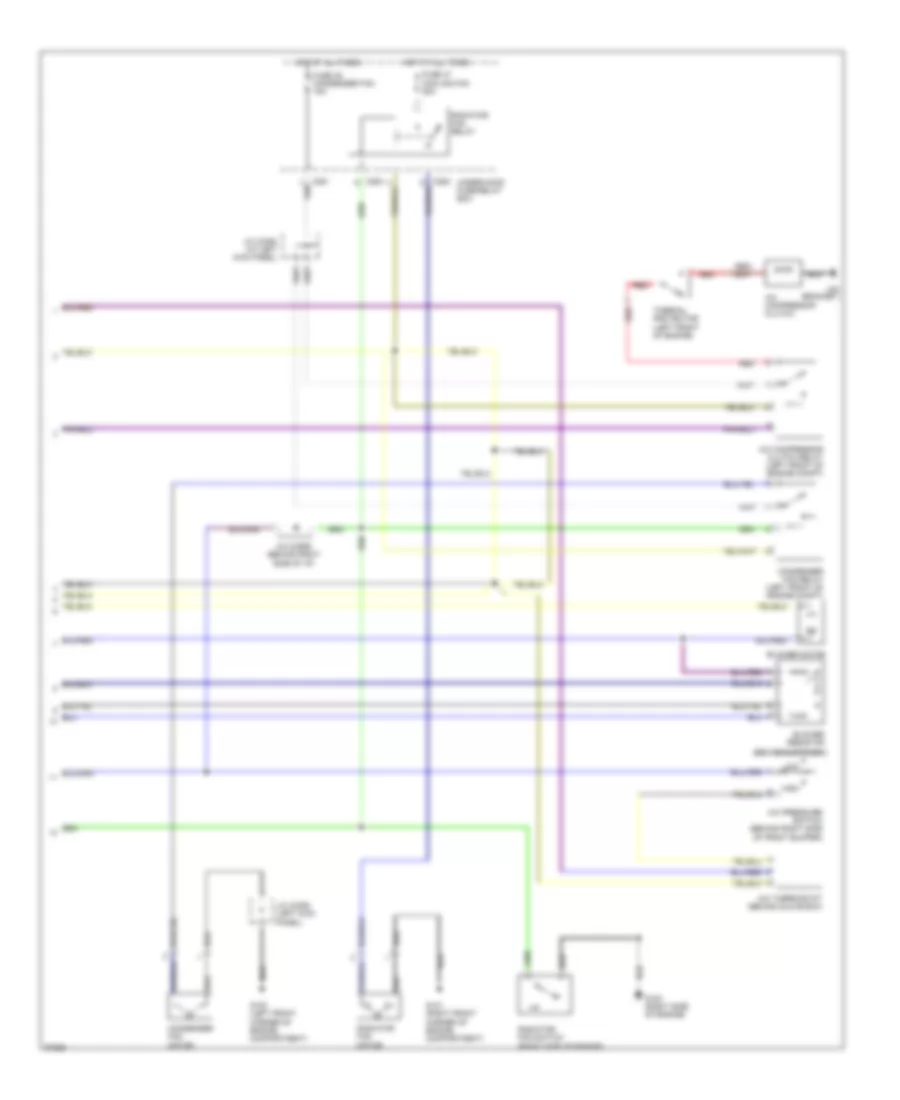
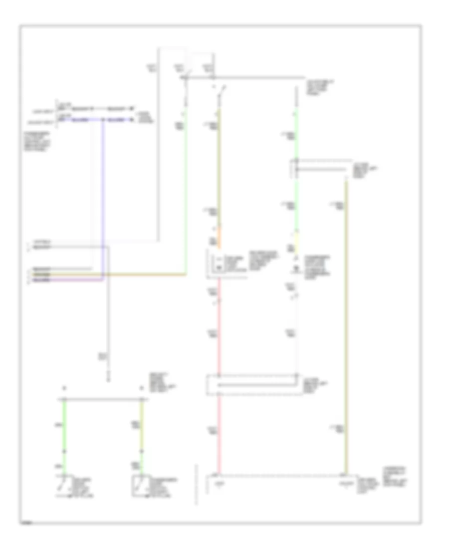
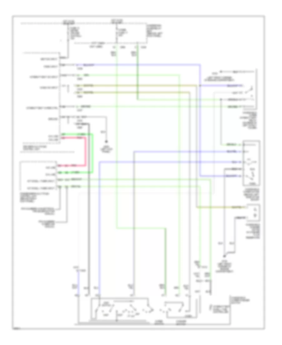
AIR CONDITIONING
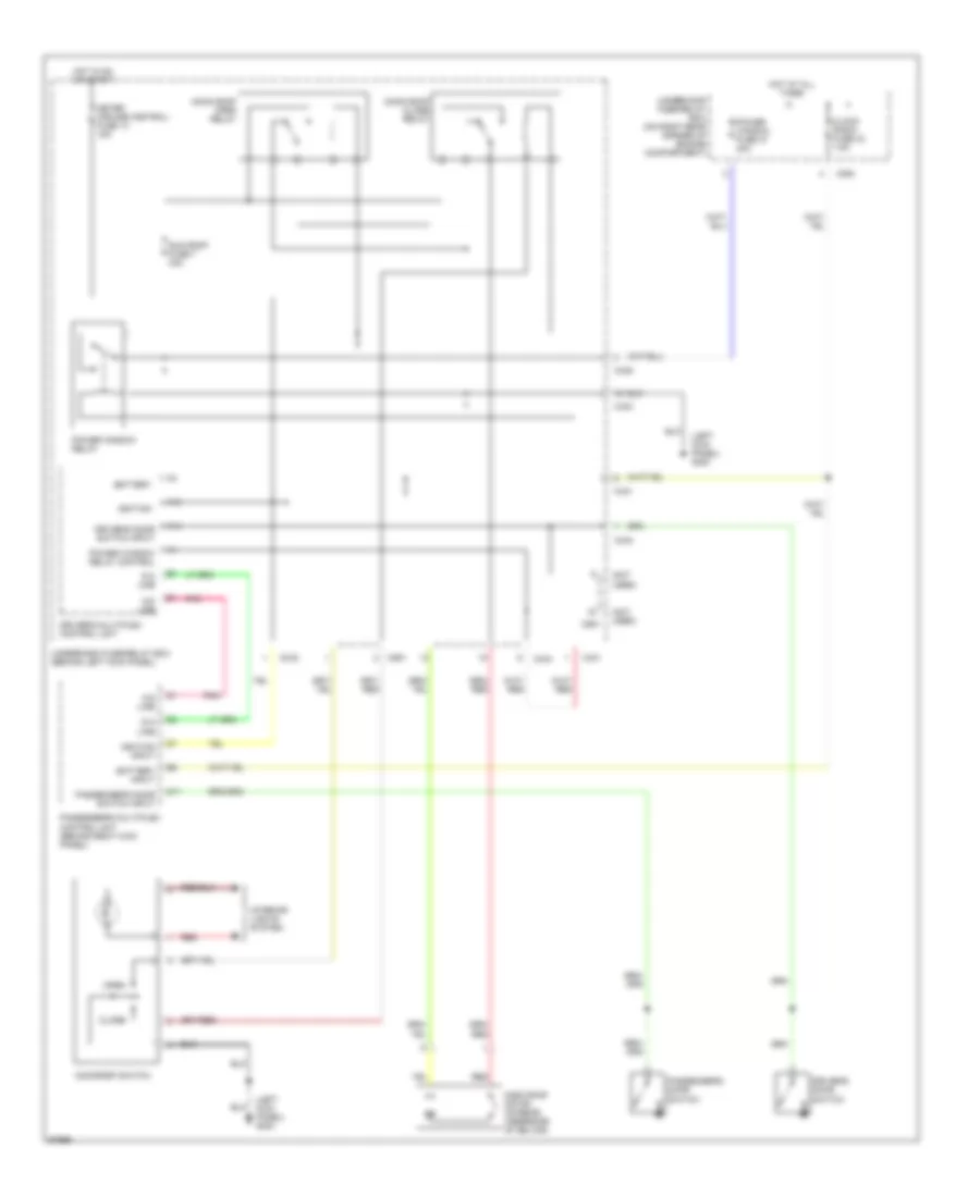
Air Conditioning Wiring Diagrams (1 of 2) for Honda Prelude 1997
 https://portal-diagnostov.com/license.html
Automotive Electricians Portal FZCO
Automotive Electricians Portal FZCO
https://portal-diagnostov.com/license.html
https://portal-diagnostov.com/license.html
Automotive Electricians Portal FZCO
Automotive Electricians Portal FZCO
List of elements for Air Conditioning Wiring Diagrams (1 of 2) for Honda Prelude 1997:
- (behind glove box)
- (behind right side of dash)
- (behind right side of i/p) g201
- A/c on
- A17
- A27
- Bi-lev switch
- Blower motor relay
- C253
- C254
- C432
- C433
- C436
- Defrost switch
- Dimming circuit
- Driving circuit
- Engine control module (right front floor, under carpet)
- Fresh
- Fresh/recirc and a/c switch
- Fuse 35 heater motor 40a
- Fuse 43 clock radio 7.5a
- Fuse 9 7.5a
- G200 (left kick panel)
- G201
- Heat switch
- Heat/def switch
- Heater control panel
- Heater fan switch
- Hot at all times
- Hot in on
- Ind
- Interior lights system
- Mode control motor (below i/p, right of steering column)
- Off
- Recirc
- Recirculation control motor
- Red
- Under-dash fuse/relay box
- Under-hood fuse/relay box
- Vent switch
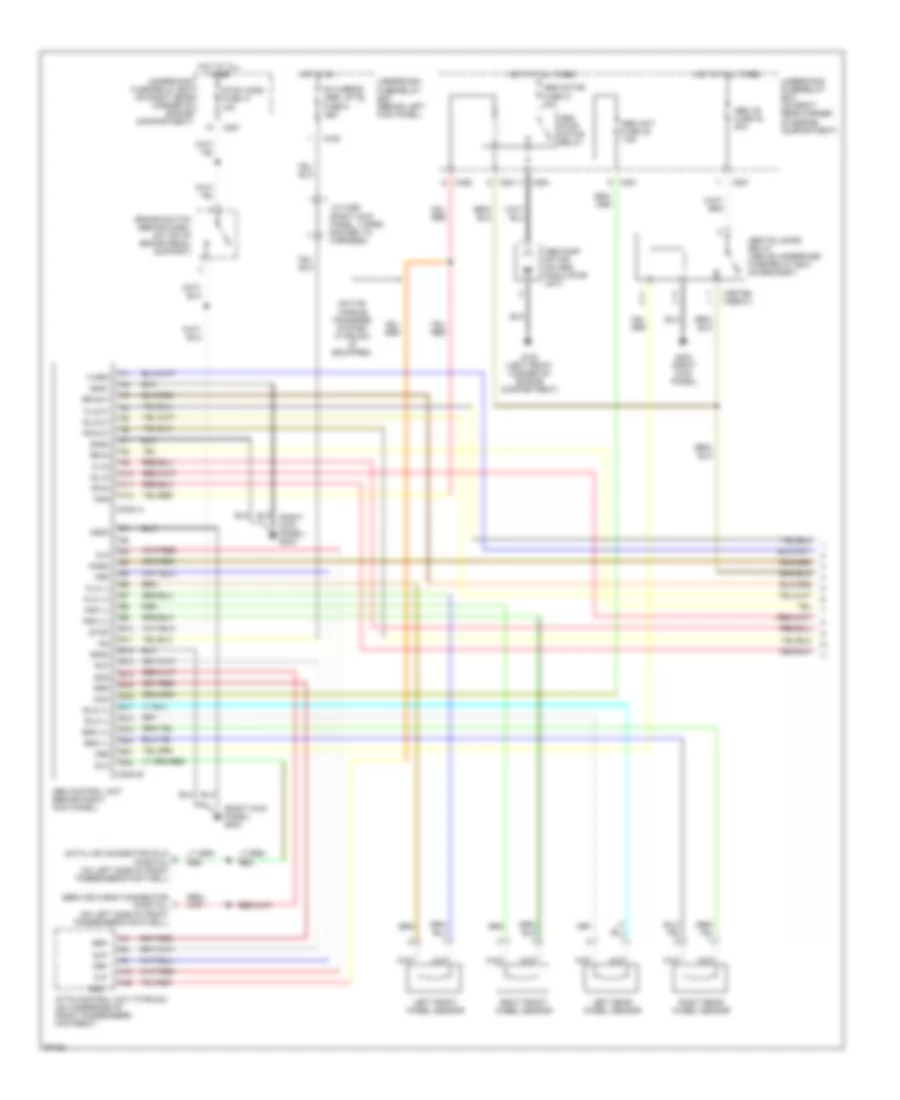
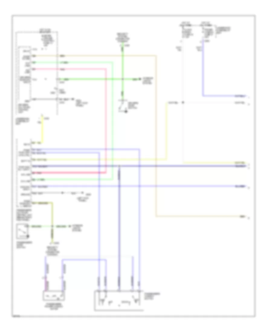
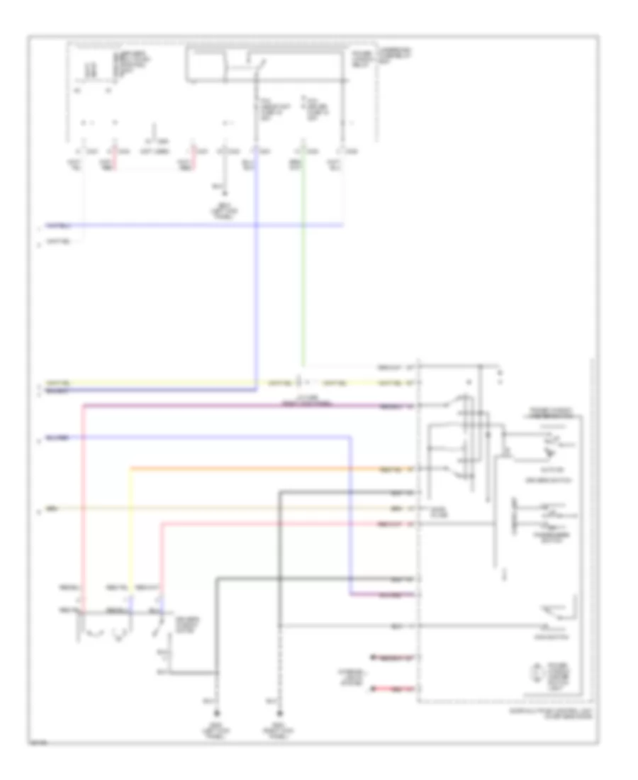
Air Conditioning Wiring Diagrams (2 of 2) for Honda Prelude 1997
List of elements for Air Conditioning Wiring Diagrams (2 of 2) for Honda Prelude 1997:
- (behind glove box)
- (on bracket)
- A/c compressor clutch
- A/c compressor clutch relay (left front of engine compt)
- A/c diode (behind right side of i/p)
- A/c pressure switch (behind right side of front bumper)
- A/c thermostat (behind glove box)
- Blower motor
- Blower resistor
- C251
- C252
- C254
- Condenser fan motor
- Condenser fan relay (left front of engine compt)
- Cooling fan 20a
- Fuse 45 condenser fan 15a
- Fuse 47
- G100 (left front corner of engine compartment)
- G101 (right front corner of engine compartment)
- G120 (right side of engine)
- High
- Hot at all times
- J/c (c306) (at left kick panel)
- J/c (c306) (left kick panel)
- Low
- Radiator fan motor
- Radiator fan relay
- Radiator fan switch (right side of engine)
- Red
- Thermal protector (left front of engine)
- Under-hood fuse/relay box
ANTI-LOCK BRAKES
Anti-lock Brake Wiring Diagrams (1 of 2) for Honda Prelude 1997
List of elements for Anti-lock Brake Wiring Diagrams (1 of 2) for Honda Prelude 1997:
- (1997-98) (1999-01)
- (right kick panel) g203
- A10
- A11
- A12
- A22
- A4
- Abs +b fuse 40 20a
- Abs control unit (behind right kick panel)
- Abs fail-safe relay (above underdash fuse/relay box, on bracket)
- Abs motor fuse 31 30a
- Abs pump motor (on abs modulator unit)
- Abs pump motor relay
- Abs unit fuse 48 7.5a
- Absy
- Active torque transfer system (type sh) (if equipped)
- Atts control unit (type sh) (on underside of front passenger's footrest)
- B10
- B11
- B12
- B13
- B14
- B15
- B16
- B17
- B18
- B19
- B20
- B21
- B22
- Brake switch (behind dash, on top of brake pedal support)
- C251
- C252
- C254
- C438
- Conn a
- Conn b
- Data link connector (dlc) (partial) (on left side of front passenger's footwell)
- Dlc
- Fl-in
- Fl-out
- Flp
- Flw (+)
- Flw (-)
- Fr-in
- Fr-out
- Frp
- Frw (+)
- Frw (-)
- Fsr
- G100 (left front corner of engine compartment)
- G203 (right kick panel)
- Gnd1
- Gnd2
- Gnd3
- Gnd4
- Hot at all times
- Hot in on
- Ig2
- J/c c456 (right kick panel, taped backed to harness)
- Left front wheel sensor
- Left rear wheel sensor
- Mck
- Park
- Pmr
- R/c mirror (abs, atts) fuse 9 7.5a
- Right front wheel sensor
- Right rear wheel sensor
- Rl-in
- Rl-out
- Rlp
- Rlw (+)
- Rlw (-)
- Rr-in
- Rr-out
- Rrp
- Rrw (+)
- Rrw (-)
- Scs
- Service check connector (partial) (on left side of front passenger's footwell)
- Stop
- Stop horn fuse 41 15a
- Underdash fuse/relay box (behind left kick panel)
- Underhood fuse/relay box (on right rear corner of engine compartment)
- Warn
Anti-lock Brake Wiring Diagrams (2 of 2) for Honda Prelude 1997
List of elements for Anti-lock Brake Wiring Diagrams (2 of 2) for Honda Prelude 1997:
- (left front corner of engine compartment)
- (left kick panel) g200
- Abs indicator circuit
- Abs indicator light
- Abs modulator unit (in left front of engine compartment)
- Brake fluid level switch (in brake fluid reservoir cap)
- Brake ind out
- C551
- Canadian models
- Daytime running lights (drl) control unit (behind dash, above accelerator pedal)
- G100
- Gauge assembly
- Hot in on or start
- J/c c306 (left kick panel)
- J/c c456 (right kick panel, taped back to harness)
- J/c c559 (behind gauge assembly)
- Left front abs solenoid (in)
- Left front abs solenoid (out)
- Left rear abs solenoid (in)
- Left rear abs solenoid (out)
- Meter cruise control fuse 13 15a
- Park brake sw in
- Parking brake switch (at base of park brake lever)
- Right front abs solenoid (in)
- Right front abs solenoid (out)
- Right rear abs solenoid (in)
- Right rear abs solenoid (out)
- Underdash fuse/relay box (behind left kick panel)
- Us models
ANTI-THEFT
Anti-theft Wiring Diagram (1 of 2) for Honda Prelude 1997
List of elements for Anti-theft Wiring Diagram (1 of 2) for Honda Prelude 1997:
- (left front corner of engine compartment) g100
- (left kick panel) g200
- (right kick panel) g203
- (right rear of trunk) g405
- 15a
- 7.5a
- Antenna
- Antenna input
- Battery
- C251
- C254
- C551
- Clock radio fuse 43 7.5a
- Disarm/ valet switch (on lower left dash panel)
- Disarm/valet sw in
- Door open input
- Dr unlck rly ctrl
- Ecu eat ecu fuse 14 15a
- Exterior & interior light systems
- Glass breakage microphone
- Ground
- Hood sw input
- Hood switch (on front of engine compartment, next to hood latch)
- Horn ctrl
- Horns system
- Hot at all times
- Hot in on or start
- Ign key sw input
- Ignition
- Ignition key switch
- Light flash ctrl
- Light flasher relay (on back of lower left dash panel)
- Lock output
- Nca
- Optional
- Power distribution system
- Red
- Sec ind ctrl
- Security control unit (behind dash, above accelerator pedal)
- Security in-line fuse holder 1 (behind dash, above left kick panel)
- Security in-line fuse holder 2 (behind lower dash panel, left of steering column, taped to harness)
- Security in-line fuse holder 3 (behind lower dash panel, left of steering column, taped to harness)
- Security indicator
- Siren (behind left side of front bumper) (optional)
- Siren ctrl
- Small light fuse 42 20a
- Steering lock
- Trunk latch switch (on center of trunk lid, at latch assembly)
- Trunk open input
- Underdash fuse/relay box (behind left kick panel)
- Underhood fuse/relay box (on right rear corner of engine compartment)
- Unlock output
- Warning systems
Anti-theft Wiring Diagram (2 of 2) for Honda Prelude 1997
List of elements for Anti-theft Wiring Diagram (2 of 2) for Honda Prelude 1997:
- (d4 or b4)
- (d5 or b5)
- Door locks system
- Driver's door lock actuator
- Driver's door lock assembly (in rear of driver's door)
- Driver's door switch (in left "b" pillar)
- Driver's multiplex control unit
- J/c c406 (behind left side of dash)
- Lock +
- Lock input
- Passenger's door lock actuator (in rear of passenger's door)
- Passenger's door switch (in right "b" pillar)
- Passenger's multiplex control unit (behind right kick panel)
- Security diodes (behind driver's left air vent)
- Underdash fuse/relay box (behind left kick panel)
- Unlock +
- Unlock input
- Unlock relay (on lower left dash panel)
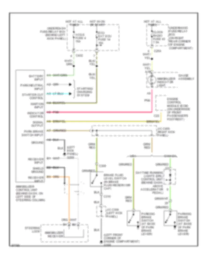
Immobilizer Wiring Diagram for Honda Prelude 1997
List of elements for Immobilizer Wiring Diagram for Honda Prelude 1997:
- (left front corner of engine compartment) g100
- (left kick panel) g200
- A1 battery input
- A10
- A2 park/neutral input
- A3 starter cut control
- A4 ignition input
- A5 indicator control
- A6 signal output
- A7 park brake switch input
- Acg-s fuse 4 15a
- B1 receiver input
- B2 shield ground
- B3 receiver input
- Brake fluid level switch (in brake fluid reservoir cap)
- C22
- C254
- C309
- C310
- C432
- Canada
- Clock radio fuse 43 7.5a
- Daytime running lights (drl) control unit (behind dash, above accelerator pedal)
- Ecu eat ecu fuse 14 15a
- Engine control module (ecm) (on underside of front passenger's footrest)
- Gauge assembly
- Ground
- Hot at all times
- Hot in on or start
- Immobilizer control unit (behind dash, on left side of steering column)
- Immobilizer indicator light
- Immobilizer receiver
- J/c c306 (left kick panel)
- J/c c456 (right kick panel)
- Parking brake switch (at base of park brake lever)
- Pnk
- Starting/ charging system
- Steering lock
- Underdash fuse/relay box (behind left kick panel)
- Underhood fuse/relay box (on right rear corner of engine compartment)
- Usa
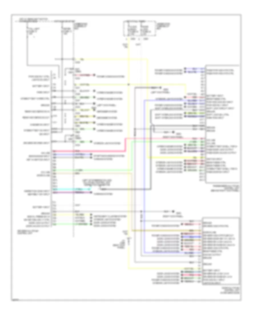
BODY COMPUTER
Multiplex Control Wiring Diagram for Honda Prelude 1997
List of elements for Multiplex Control Wiring Diagram for Honda Prelude 1997:
- (left kick panel)
- (left of steering column) multiplex control unit inspection connector
- (not used) c551
- (right kick panel)
- A-d line
- A10
- A11
- A12
- A13
- A14
- A15
- A16
- A17
- A18
- A19
- A20
- B10
- B11
- B12
- B13
- B14
- Battery input
- Brightness ctrl
- C254
- C431
- C432
- C433
- C434
- C436
- C437
- C980
- Clock radio fuse 43 7.5a
- D-a line
- Defogger system
- Door d-line
- Door lock fuse 44 10a
- Door lock output
- Door locks system
- Door multiplex control unit (in driver's door)
- Door unlock output
- Driver's door key cyl sw in
- Driver's dr knob sw lk in
- Driver's dr knob sw unlk in
- Driver's dr lk sw lk in
- Driver's dr lk sw unlk in
- Driver's dr open input
- Driver's multiplex control unit
- Driver's wdo mtr ctrl
- Driver's wdo mtr plsr out
- Eng oil press sw in
- Eng running input
- G200
- G203
- Ground
- Hot at all times
- Hot in on or start
- Hot w/ headlight switch in park or head
- Ign input
- Ign key/ceiling lt ctrl
- Ignition input
- Inspection conn input
- Instrument cluster system
- Interior lights system
- Intermittent dwell tmr in
- Intermittent on input
- Intermittent wiper ctrl
- J/c c456 (right kick panel)
- Key in ignition input
- Lights on input
- Main sw output
- Meter fuse 13 15a
- Park input
- Park pos input
- Pass door lock output
- Pass door sw input
- Pass door unlock output
- Pass pwr wdo mtr ctrl
- Passenger's multiplex control unit (behind right kick panel)
- Pnk
- Power windows system
- Pwr wdo main sw input
- Pwr wdo rly ctrl
- Pwr wdo rly input
- Rear wdo defog on in
- Rear wdo defog on out
- Red
- Seatbelt sw input
- Shift interlock system
- Shift lock circuit input
- Shift lock sol ctrl
- Starting/charging system
- Tail light fuse 10 15a
- Under-dash fuse/relay box
- Under-hood fuse/relay box
- Warning system
- Washer on input
- Wiper/washer system
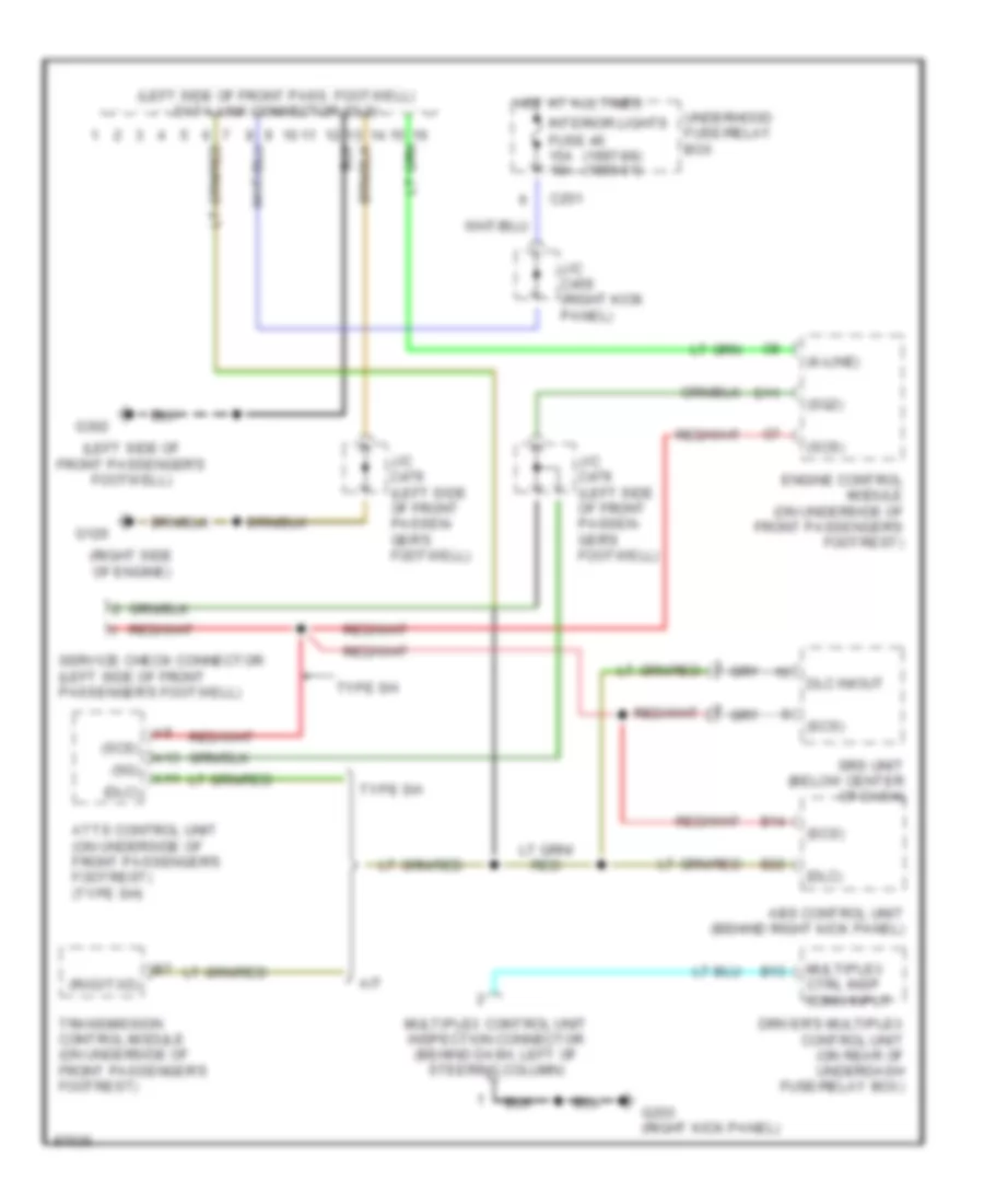
COMPUTER DATA LINES
Computer Data Lines for Honda Prelude 1997
List of elements for Computer Data Lines for Honda Prelude 1997:
- (1997-98) (1999-01)
- (dlc)
- (k-line)
- (left side of front pass. footwell) data link connector (dlc)
- (left side of front passenger's footwell)
- (right side of engine)
- (rxd/txd)
- (scs)
- (sg)
- (sg2)
- A/t
- A11
- A13
- Abs control unit (behind right kick panel)
- Atts control unit (on underside of front passenger's footrest) (type sh)
- B13
- B14
- B22
- C251
- D11
- Dlc in/out
- Driver's multiplex control unit (on rear of underdash fuse/relay box)
- Engine control module (on underside of front passenger's footrest)
- Fuse 46 15a 10a
- G120
- G203 (right kick panel)
- G302
- Hot at all times
- Interior lights
- J/c c456 (right kick panel)
- J/c c479 (left side of front passen- ger's footwell)
- Multiplex control unit inspection connector (behind dash, left of steering column)
- Multiplex ctrl insp conn input
- Service check connector (left side of front passenger's footwell)
- Srs unit (below center of dash)
- Transmission control module (on underside of front passenger's footrest)
- Type sh
- Underhood fuse/relay box
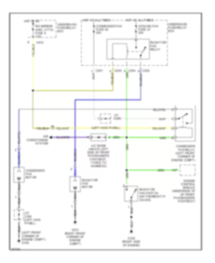
COOLING FAN
Cooling Fan Wiring Diagram for Honda Prelude 1997
List of elements for Cooling Fan Wiring Diagram for Honda Prelude 1997:
- (left front corner of engine compt) g100
- (left kick panel)
- A/c diode (above left side of front passenger's footrest, taped to harness)
- A27
- Air conditioning system
- C251
- C252
- C254
- C432
- Condenser fan fuse 45 20a
- Condenser fan motor
- Condenser fan relay (left front corner of engine compt)
- Cooling fan fuse 47 20a
- Engine control module (underside of of front passenger's footrest)
- G101 (right front corner of engine compt)
- G120 (right side of engine)
- Hot at all times
- Hot in on
- J/c c306
- J/c c306 (left kick panel)
- R/c mirror (abs, atts) fuse 9 7.5a
- Radiator fan motor
- Radiator fan relay
- Radiator fan switch (on thermostat cover)
- Underdash fuse/relay box
- Underhood fuse/relay box
CRUISE CONTROL
Cruise Control Wiring Diagram for Honda Prelude 1997
List of elements for Cruise Control Wiring Diagram for Honda Prelude 1997:
- "on" indicator
- (1997-98) (1999-01)
- (left kick panel) g200
- (left side of front passenger's footwell) g302
- A/t
- A/t gear position switch (on lower rear of transaxle)
- A11
- Actuator ctrl
- Brake switch (on top of brake pedal support)
- Brake switch input
- C251
- C433
- C551
- Cable reel (on top of steering column, below steering wheel)
- Canada
- Clutch switch (on top of clutch pedal support)
- Cruise control actuator (on right rear of engine compartment)
- Cruise control indicator light
- Cruise control main switch
- Cruise control main switch light
- Cruise control set/ resume switch
- Cruise control unit (behind dash, above accelerator pedal)
- Cruise ind lt ctrl
- Dimming circuit
- Disengage input
- Gauge assembly
- Ground
- Horn relay (above underdash fuse/relay box, on bracket)
- Horns system
- Hot at all times
- Hot in on or start
- Interior lights system
- J/c c479 (left side of passengers, footwell, taped to harness)
- J/c c559 (behind gauge assembly)
- M/t
- Meter (cruise control) fuse 13 15a
- Off
- Pnk
- Power input
- Red
- Resume/ accel switch
- Resume/accel sig in
- Safety solenoid
- Set/ decel switch
- Set/decel sig input
- Steering wheel
- Stop horn fuse 41 15a
- U.s.
- Underdash fuse/relay box (behind left kick panel)
- Underhood fuse/relay box (on right rear corner of engine compartment)
- Vacuum solenoid
- Vehicle speed senser (vss) (on top left of transaxle)
- Vent solenoid
- Vss input
- Vss output
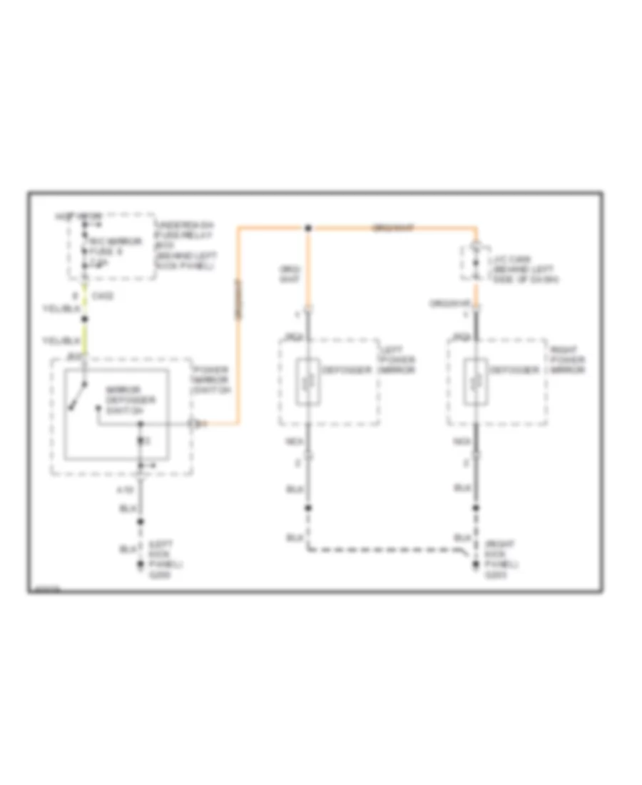
DEFOGGERS
Heated Mirrors Wiring Diagram for Honda Prelude 1997
List of elements for Heated Mirrors Wiring Diagram for Honda Prelude 1997:
- (left kick panel) g200
- (right kick panel) g203
- A10
- C432
- Defogger
- Hot in on
- J/c c406 (behind left side of dash)
- Left power mirror
- Mirror defogger switch
- Nca
- Power mirror switch
- R/c mirror fuse 9 7.5a
- Right power mirror
- Underdash fuse/relay box (behind left kick panel)
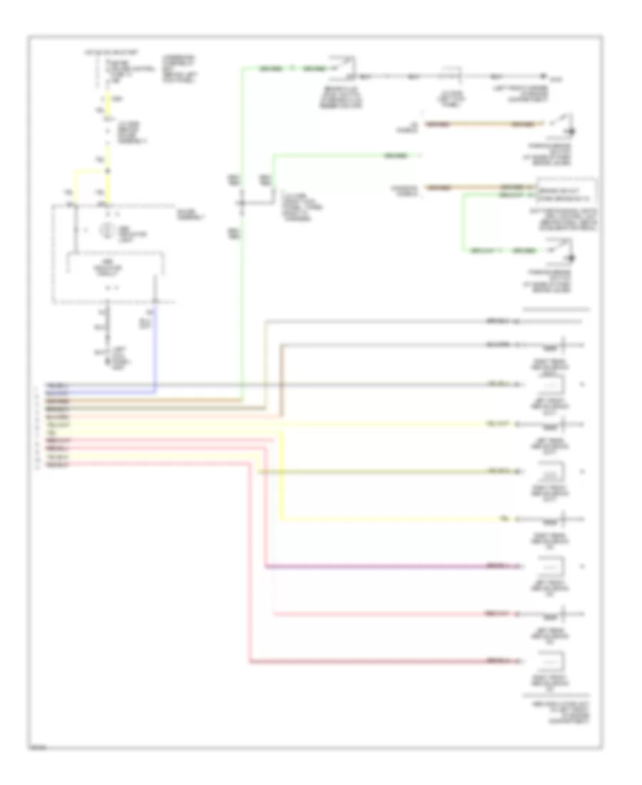
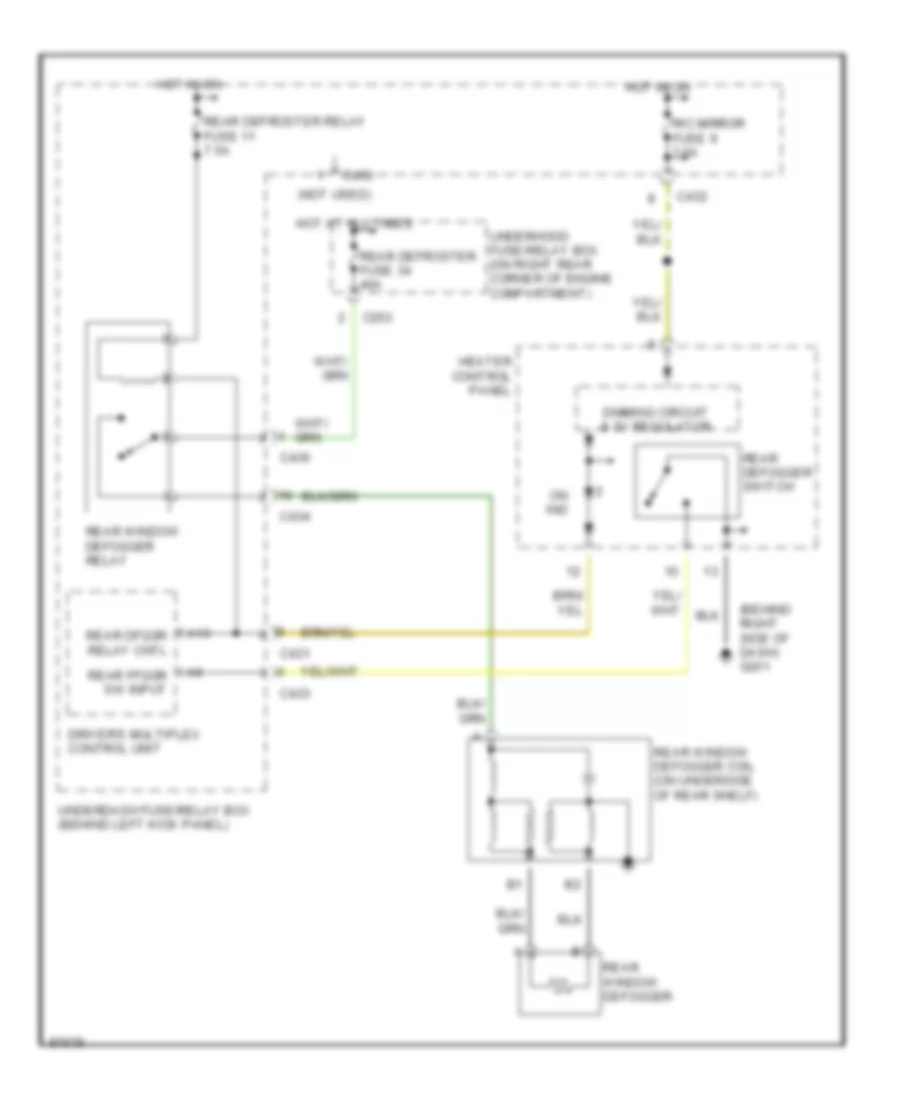
Rear Defogger Wiring Diagram for Honda Prelude 1997
List of elements for Rear Defogger Wiring Diagram for Honda Prelude 1997:
- (behind right side of dash) g201
- (not used)
- A10
- C253
- C431
- C432
- C433
- C434
- C436
- Dimming circuit & 5v regulator
- Driver's multiplex control unit
- Heater control panel
- Hot at all times
- Hot in on
- On ind
- R/c mirror fuse 9 7.5a
- Rear defogger switch
- Rear defroster fuse 34 40a
- Rear defroster relay fuse 11 7.5a
- Rear dfggr relay cntl
- Rear ffggr sw input
- Rear window defogger
- Rear window defogger coil (on underside of rear shelf)
- Rear window defogger relay
- Underdash fuse/relay box (behind left kick panel)
- Underhood fuse/relay box (on right rear corner of engine compartment)
ENGINE PERFORMANCE
2.2L
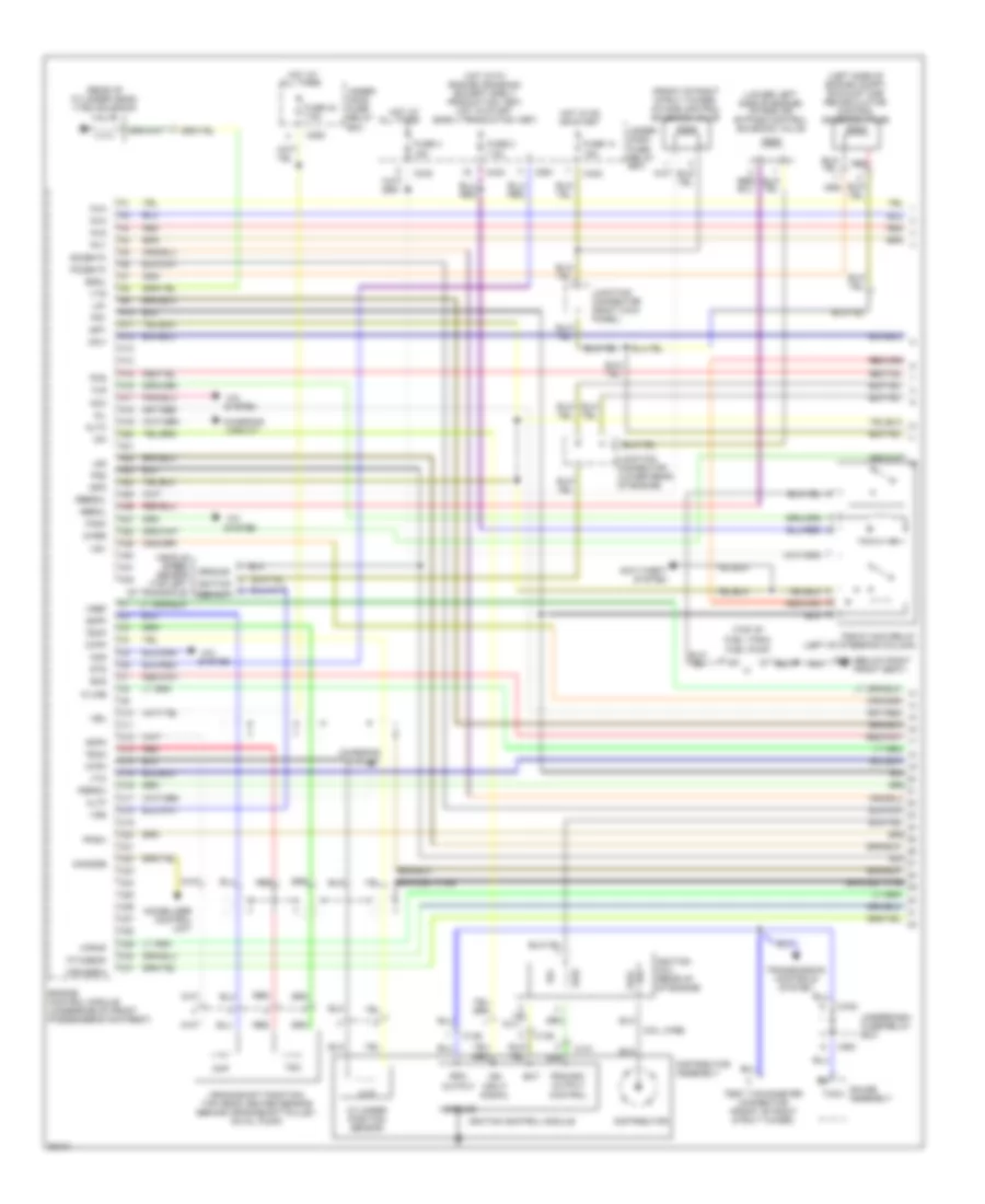
2.2L, Engine Performance Wiring Diagrams (1 of 3) for Honda Prelude 1997
List of elements for 2.2L, Engine Performance Wiring Diagrams (1 of 3) for Honda Prelude 1997:
- (below right g301 front seat)
- (front of right strut tower) intake control solenoid valve
- (left side of engine compt) exhaust gas recirculation control solenoid valve
- (lower left side of engine) intake air bypass control solenoid valve
- (rear of cylinder head) vtec solenoid valve
- (top of fuel tank)
- 2wbs
- A/c
- A10
- A11
- A12
- A13
- A14
- A15
- A16
- A17
- A18
- A19
- A20
- A21
- A22
- A23
- A24
- A25
- A26
- A27
- A28
- A29
- A30
- A31
- A32
- Acc
- Acs
- All times
- Altc
- Altf
- Anti-theft system
- Atpnp
- Bat
- Box
- Braided wire
- C10
- C11
- C12
- C13
- C131
- C136
- C14
- C15
- C16
- C17
- C18
- C19
- C20
- C21
- C22
- C23
- C24
- C25
- C254
- C26
- C27
- C28
- C29
- C30
- C31
- C432
- C433
- C551
- Charging circuit
- Ckp
- Ckpm
- Ckpp
- Coil wire
- Crankshaft position/ top dead center sensor (behind crankshaft pulley, on oil pump)
- Cylinder position sensor
- Cyp
- Cypm
- Cypp
- Distributor
- Distributor assembly
- Engine control module (underside of front passenger's footrest)
- Esol
- Fanc
- Firx/sefa
- Fitx/seaf
- Flr
- Fuel pump
- Fuse 14 15a
- Fuse 2 7.5a
- Fuse 4 15a
- Fuse 43 7.5a
- Gauge assembly
- Ground
- Hot at
- Hot at all times
- Hot in on or start
- Hot with engine cranking (except early production 1997) hot in start (early production 1997)
- Iabsol
- Iacv
- Icm
- Ign input signal
- Ignition coil (rear of of engine)
- Ignition control module
- Igp1
- Igp2
- Immobilizer control unit
- Imocode
- Inj1
- Inj2
- Inj3
- Inj4
- Junction connector (lower rear of engine)
- Junction connector (right kick panel)
- K-line
- Lg1
- Lg2
- Mil
- Of transaxle) vss out
- Pcs
- Pfsw
- Pg1
- Pg2
- Pgm-fi main relay (left of steering column)
- Po2shtc
- Pri
- Primary output control
- Pspsw
- Red
- Ressol
- Rpm output
- Scs
- Sec
- So2shtc
- Sts
- System
- Tach
- Tdc
- Tdcm
- Tdcp
- Test tachometer connector (front of right strut tower)
- Transmission controls system
- Under- dash fuse/ relay box
- Under- hood fuse/ relay
- Underdash fuse/relay box
- Vbu
- Vehicle speed sensor (top left ignition
- Vref
- Vss
- Vsv
- Vtm
- Vts
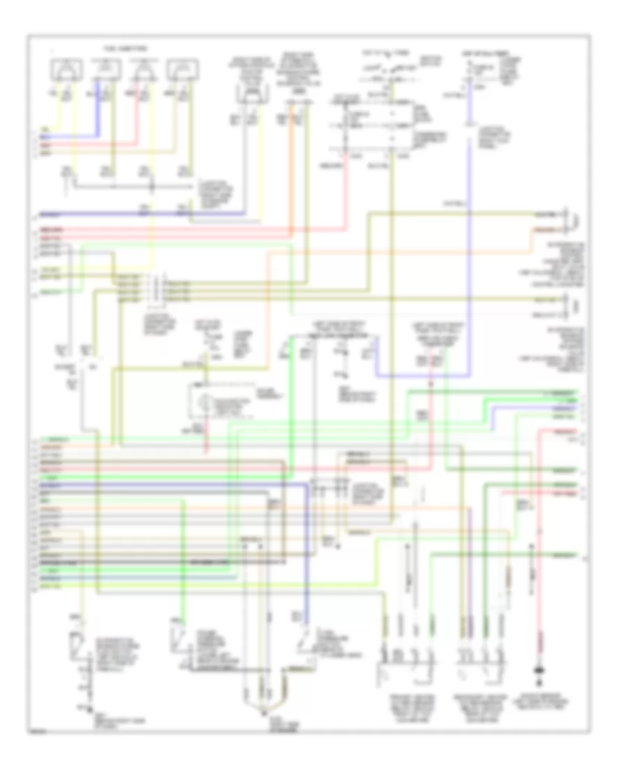
2.2L, Engine Performance Wiring Diagrams (2 of 3) for Honda Prelude 1997
List of elements for 2.2L, Engine Performance Wiring Diagrams (2 of 3) for Honda Prelude 1997:
- (left side of front pass. footwell)
- (left side of front pass. footwell) data link connector
- (right side of firewall) evaporative emission purge control solenoid valve
- (right side of intake manifold)
- Acc
- B16
- Braided wire
- C251
- C433
- C435
- C551
- C974
- C976
- Compartment)
- Evaporative emission bypass solenoid valve (1997 california, 1998-01) (right side of firewall)
- Evaporative emission control canister vent shut valve (1997 california, 1998-01) (top of evap control canister)
- Evaporative emission purge flow switch (1997 non-calif) (right side of firewall)
- Except sh
- Fuel injectors
- Fuse 15a
- Fuse 23 15a
- Fuse 46 15a
- G120 (right side of engine)
- G201 (behind right side of dash)
- Gauge assembly
- Hot at all times
- Hot in on or start
- Idle air control valve
- Ignition switch
- Junction connector (right kick panel)
- Junction connector (right side of dash)
- Junction connector (right side of engine compt)
- Knock sensor (left side of engine, above oil filter)
- Lock
- Malfunction indicator light (mil)
- Nca
- Power steering pressure switch (lower left rear of engine
- Primary heated oxygen sensor (below vehicle, front of twc converter)
- Red
- Secondary heated oxygen sensor (below vehicle, rear of twc converter)
- Service check connector
- Srs fuse block
- Start
- Under- dash fuse/ relay box
- Under- hood fuse/ relay box
- Underdash fuse/relay box
- Vtec pressure switch (rear of cylinder head)
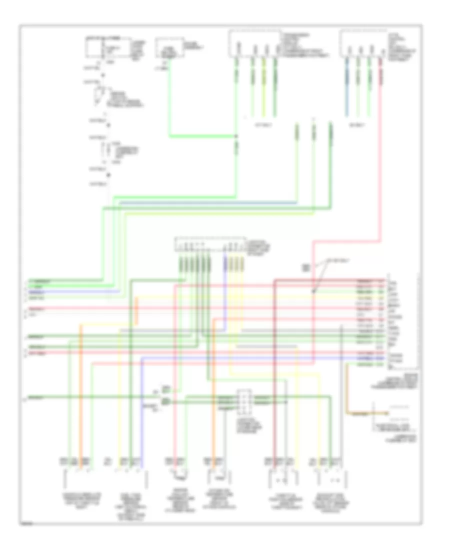
2.2L, Engine Performance Wiring Diagrams (3 of 3) for Honda Prelude 1997
List of elements for 2.2L, Engine Performance Wiring Diagrams (3 of 3) for Honda Prelude 1997:
- A/t only
- A10
- Atpnp
- Atts control unit (sh only) (underside of front pass. footrest)
- B17
- B18
- B19
- B20
- Bksw
- Brake switch (top of brake pedal support)
- C251
- C432
- C438
- D10
- D11
- D12
- D13
- D14
- D15
- D16
- Ect
- Egrl
- Electrical load detector unit
- Engine control module (underside of front passenger's footrest)
- Engine coolant temperature sensor (rear of cylinder head)
- Except sh
- Exhaust gas recirculation valve lift sensor (rear of intake manifold)
- Firx
- Fitx
- Fuel tank pressure sensor (1997 california, 1998-01) (on right side of firewall)
- Fuse 41 15a
- Gauge assembly
- Hot at all times
- Iat
- Intake air temperature sensor (front of intake manifold)
- Junction connector (lower rear of engine)
- Junction connector (right side of dash)
- Manifold absolute pressure sensor (top of throttle body)
- Map
- Park/ neutral output
- Pho2s
- Ptank
- Seaf
- Sefa
- Sg1
- Sg2
- Sh only
- Sho2s
- Throttle position sensor (side of throttle body)
- Tps
- Transmission control module (a/t only) (underside of front passenger's footrest)
- Under- hood fuse/ relay box
- Underdash fuse/relay box
- Underhood fuse/relay box
- Vcc1
- Vcc2
- Vref
- W/ sh only
EXTERIOR LIGHTS
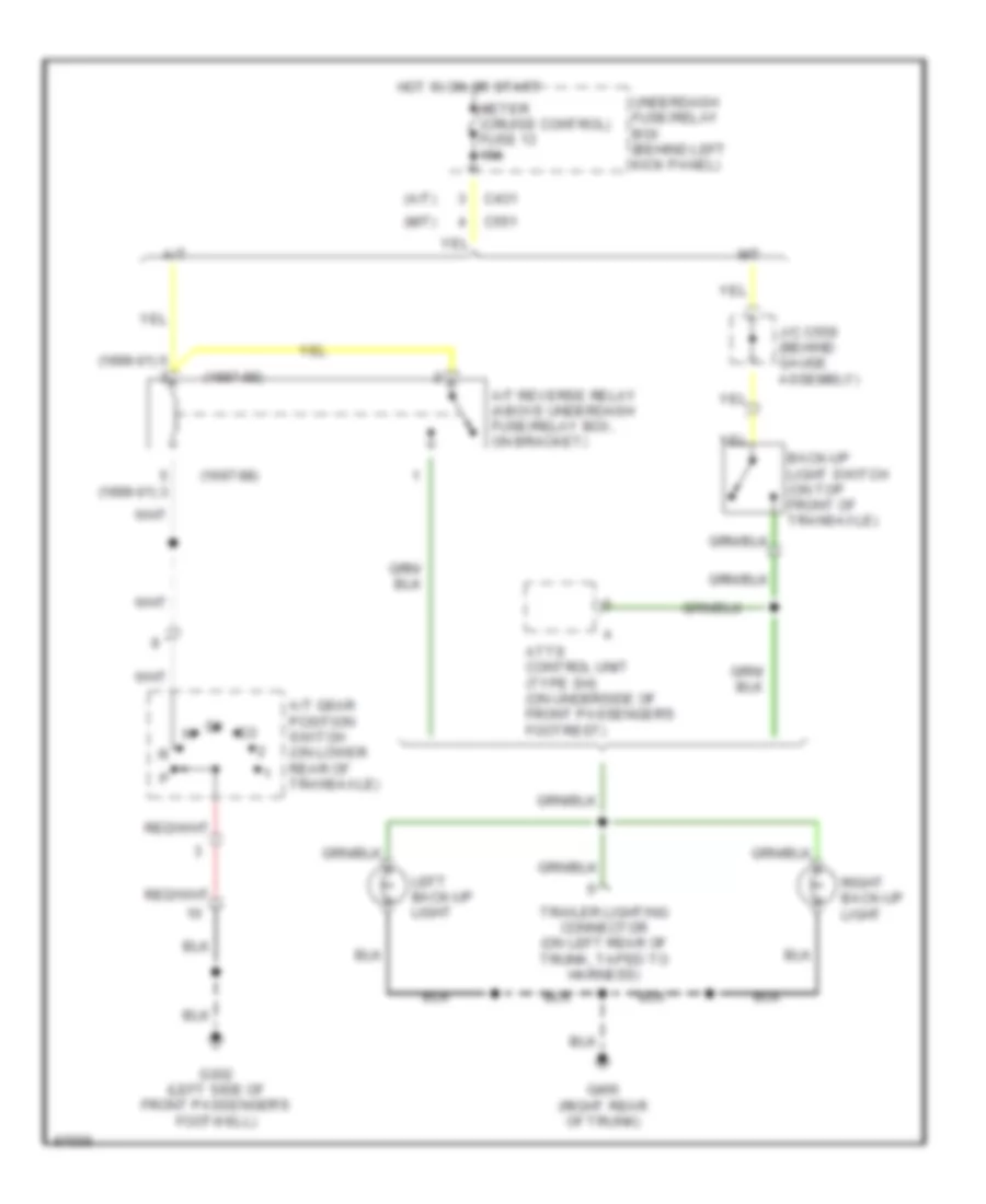
Back-up Lamps Wiring Diagram for Honda Prelude 1997
List of elements for Back-up Lamps Wiring Diagram for Honda Prelude 1997:
- (1997-98)
- (1999-01)
- (a/t)
- (m/t)
- A/t
- A/t gear position switch (on lower rear of transaxle)
- A/t reverse relay (above underdash fuse/relay box, on bracket)
- Atts control unit (type sh) (on underside of front passenger's footrest)
- Back-up light switch (on top front of transaxle)
- C431
- C551
- G302 (left side of front passenger's footwell)
- G405 (right rear of trunk)
- Hot in on or start
- J/c c559 (behind gauge assembly)
- Left back-up light
- M/t
- Meter (cruise control) fuse 13 15a
- Right back-up light
- Trailer lighting connector (on left rear of trunk, taped to harness)
- Underdash fuse/relay box (behind left kick panel)
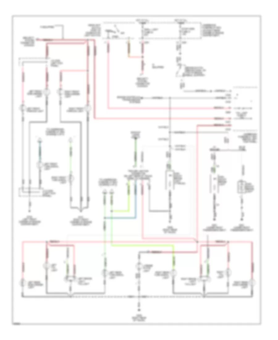
Exterior Lamps Wiring Diagram (1 of 2) for Honda Prelude 1997
List of elements for Exterior Lamps Wiring Diagram (1 of 2) for Honda Prelude 1997:
- Backup lamps circuit
- Brake switch (behind dash, on top of brake pedal support)
- Bulb type
- C251
- C431
- C432
- C434
- C438
- C980
- Engine controls & transmissions systems
- G100 (left front corner of engine compartment)
- G101 (right front corner of engine compartment)
- G301 (under front passenger's seat)
- G405 (right rear of trunk)
- Head
- Headlight switch (part of combination light switch)
- High mount brake light
- High mount brake light (type sh)
- Hot at all times
- If equipped
- J/c c306 (left kick panel)
- Left brake light/ taillight
- Left front parking light
- Left front side marker light
- Left front turn signal light
- Left rear side marker light
- Left rear turn signal light
- Left tail light
- License plate light
- Off
- Park
- Right brake light/ taillight
- Right front parking light
- Right front side marker light
- Right front turn signal light
- Right rear side marker light
- Right rear turn signal light
- Right tail light
- Security system connector (canada)
- Small light fuse 42 20a
- Stop horn fuse 41 15a
- Tail light fuse 10 15a
- To underdash fuse/relay box (diagram 2 of 2)
- Trailer lighting connector (on left rear of trunk, taped to harness)
- Underdash fuse/relay box (behind left kick panel)
- Underhood fuse/relay box (on right rear corner of engine compartment)
- W/ spoiler
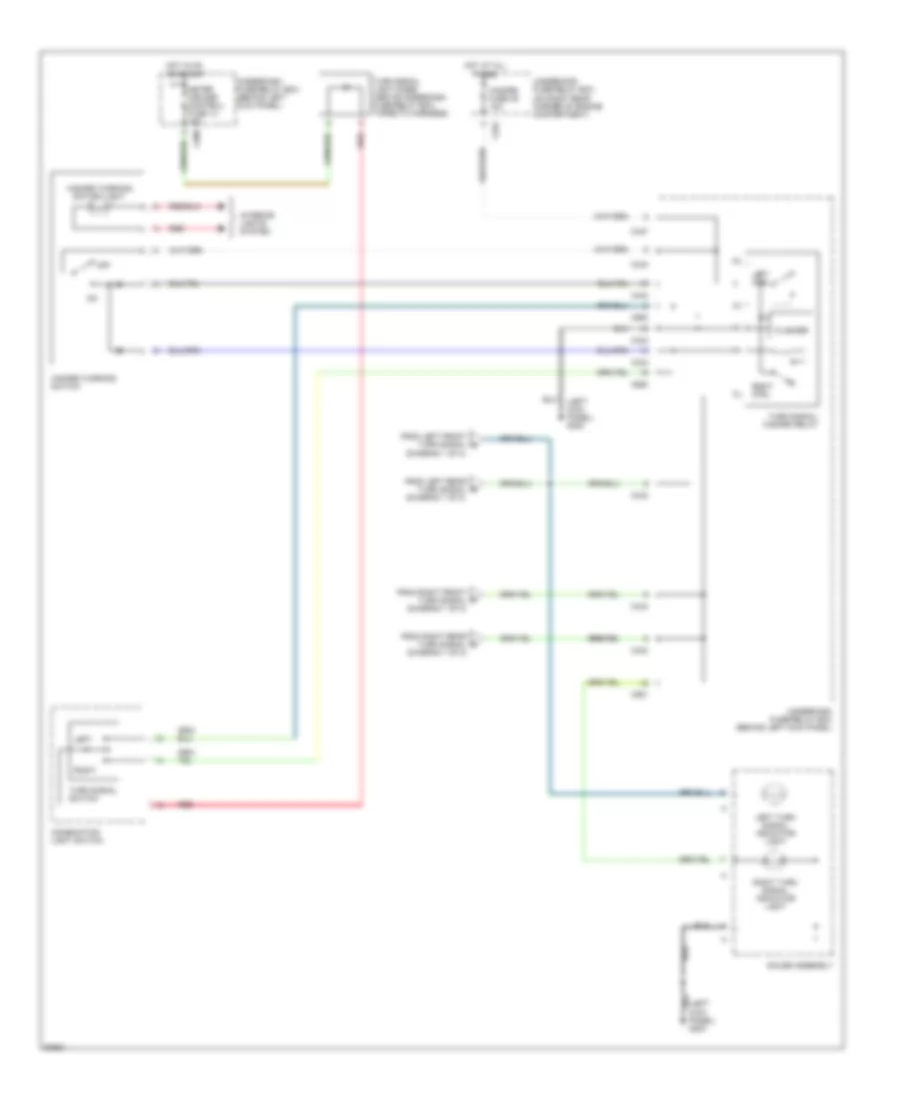
Exterior Lamps Wiring Diagram (2 of 2) for Honda Prelude 1997
List of elements for Exterior Lamps Wiring Diagram (2 of 2) for Honda Prelude 1997:
- (left kick panel) g200
- C252
- C433
- C434
- C437
- C551
- C980
- Combination light switch
- Flasher
- From left front turn signal (diagram 1 of 2)
- From left rear turn signal (diagram 1 of 2)
- From right front turn signal (diagram 1 of 2)
- From right rear turn signal (diagram 1 of 2)
- Gauge assembly
- Hazard fuse 39 10a
- Hazard warning switch
- Hazard warning switch light
- Hot at all times
- Hot in on or start
- Interior lights system
- Left
- Left ctrl
- Left turn signal indicator light
- Meter (cruise control) fuse 13 15a
- Off
- Red
- Right
- Right ctrl
- Right turn signal indicator light
- Turn signal light diode (above underdash fuse/relay box, taped to harness)
- Turn signal switch
- Turn signal/ hazard relay
- Underdash fuse/relay box (behind left kick panel)
- Underhood fuse/relay box (on right rear corner of engine compartment)
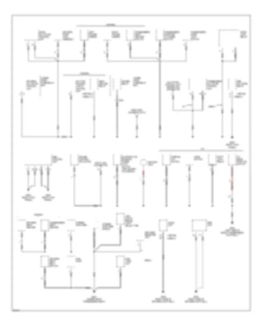
GROUND DISTRIBUTION
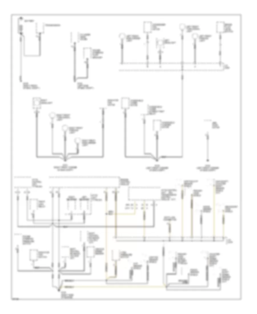
Ground Distribution Wiring Diagram (1 of 4) for Honda Prelude 1997
List of elements for Ground Distribution Wiring Diagram (1 of 4) for Honda Prelude 1997:
- (a/t)
- (sh)
- Abs pump motor
- Atts control unit (type sh)
- Atts control unit transmission control module
- Atts unit (type sh)
- Battery
- Braided
- Braided wire
- Brake fluid level switch
- Ckp/tdc sensor shield
- Ckp/tdc/cyp sensor shield
- Condenser fan motor
- Counter- shaft speed sensor shield (a/t)
- Cylinder head cover
- Cyp sensor shield wire
- Data link connector
- Engine control module
- G100 (left front corner of eng compt)
- G101 (right front corner of eng compt)
- G102 (left side of eng. compt.)
- G109 (right front of eng. compt.)
- G120 (right side of engine)
- J/c c306
- J/c c479
- Knock sensor shield
- Left front parking light
- Left front side marker light
- Left front turn signal light
- Left headlight
- Left solenoid
- Main shaft speed sensor shield (a/t)
- Main shaft/ counter shaft sensor shield (a/t)
- Pgm-fi main relay
- Power steering pressure switch
- Power steering pump bracket
- Primary ho2s shield
- Primary ho2s shield (except type sh)
- Radiator fan motor
- Radiator fan switch
- Right headlight
- Right front parking light
- Right front side marker light
- Right front turn signal light
- Right solenoid
- Secondary ho2s shield
- Shift control solenoid valve b (a/t)
- Shift control solenoid valve c (a/t)
- Transmission
- Vehicle speed sensor
- Vtec pressure switch
- Windshield washer motor
- Windshield wiper intermittent relay
- Windshield wiper motor
Ground Distribution Wiring Diagram (2 of 4) for Honda Prelude 1997
List of elements for Ground Distribution Wiring Diagram (2 of 4) for Honda Prelude 1997:
- (not used)
- A/t
- Accessory power socket
- Accessory power socket relay
- Blower motor relay
- C405
- C410
- C432
- C433
- C434
- C551
- C980
- Ceiling light/ spotlights
- Clock
- Clutch interlock switch (m/t)
- Clutch switch (m/t)
- Coil
- Combination light switch
- Cruise control main switch
- Cruise control unit
- Door multiplex control unit
- Driver's door key cylinder switch
- Driver's door lock switch
- Driver's multiplex control unit
- Driver's seat heater switch (canada)
- Driver's window motor
- Electrical load detector unit
- G200 (left kick panel)
- Gauge assembly
- Ignition key switch
- Immobilizer control unit
- J/c c559
- Left horn
- Moon roof close relay
- Moon roof open relay
- Moon roof switch
- Passenger's multiplex control unit
- Power mirror switch
- Power window relay
- Right horn
- Security system control unit (canada)
- Steering lock
- To g203 (diagram 3 of 4)
- Turn signal/ hazard relay
- Underdash fuse/relay box
- Underhood fuse/relay box
- Windshield wiper/ washer switch
Ground Distribution Wiring Diagram (3 of 4) for Honda Prelude 1997
List of elements for Ground Distribution Wiring Diagram (3 of 4) for Honda Prelude 1997:
- (1997-98)
- (1999-01)
- 1999-01
- A/t
- A/t gear position switch
- Abs control unit
- Abs fail-safe relay
- Ashtray light
- Audio unit
- Braided wire
- Canada
- Coil
- Cruise control actuator
- Data link connector
- Daytime running lights control unit
- Dimmer relay
- Door lock relay
- Door multiplex control unit
- Driver's door lock assembly
- Driver's multiplex control unit
- Driver's seat belt switch
- Driver's seat heater
- Evaporative emission purge flow switch (1997 except california)
- From g200 (diagram 2 of 4)
- Fuel pump
- Fuel tank unit
- G203 (right kick panel)
- G301 (under front passenger's seat)
- G302 (left side of front passenger's footwell)
- G302 (right side of driver's footwell)
- High mount brake light (bulb type)
- Keyless receiver unit
- Left power mirror
- Mode switch
- Multiplex control unit inspection connector
- Parking pin switch
- Passenger's door key cylinder switch
- Passenger's door lock switch
- Passenger's multiplex control unit
- Passenger's seat heater
- Passenger's seat heater switch
- Red
- Right power mirror
- Seat heater relay
- Shift lock relay
- Srs unit
- Stereo amplifier
- Stereo amplifier shield
- Under- dash fuse/relay box
- Under- hood fuse/relay box
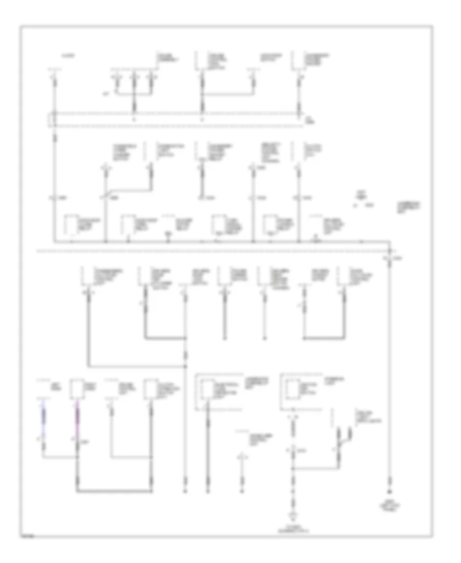
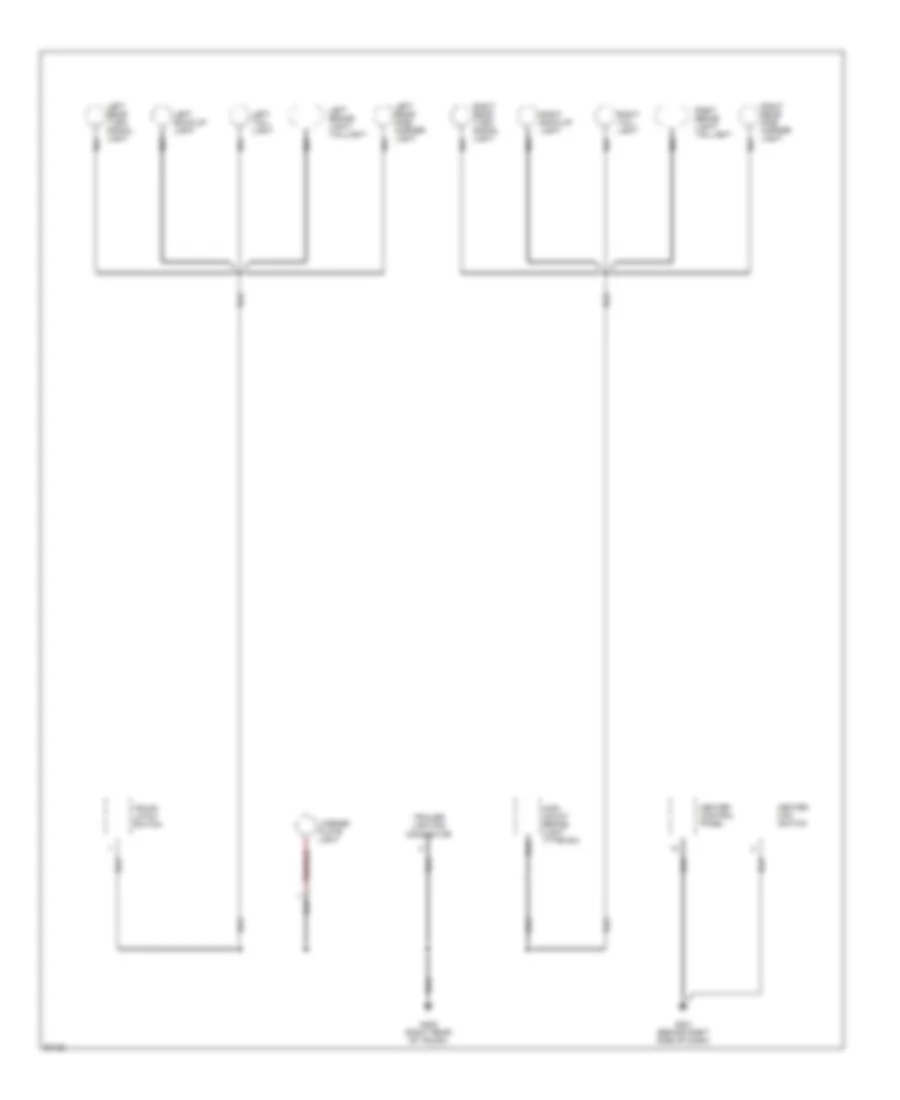
Ground Distribution Wiring Diagram (4 of 4) for Honda Prelude 1997
List of elements for Ground Distribution Wiring Diagram (4 of 4) for Honda Prelude 1997:
- G201 (behind right side of dash)
- G405 (right rear of trunk)
- Heater control panel
- Heater fan switch
- High mount brake light (type sh)
- Left back-up light
- Left brake light/ taillight
- Left rear side marker light
- Left rear turn signal light
- Left tail- light
- License plate light
- Right back-up light
- Right brake light/ taillight
- Right rear side marker light
- Right rear turn signal light
- Right tail- light
- Trailer lighting connector
- Trunk latch switch
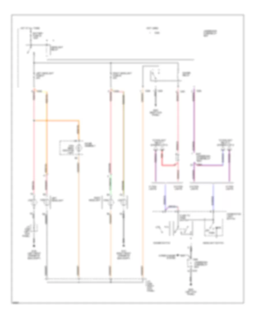
HEADLIGHTS
Headlight Wiring Diagram, with DRL (1 of 2) for Honda Prelude 1997
List of elements for Headlight Wiring Diagram, with DRL (1 of 2) for Honda Prelude 1997:
- (left front corner of eng compt)
- (left kick panel)
- (right front corner of eng compt)
- Battery fuse 32 100a
- Battery input
- Brake indicator control
- C251
- C252
- C254
- C431
- C433
- C437
- C551
- C980
- Combination light switch
- Day light fuse 8 10a
- Day light unit fuse 12 7.5a
- Daytime running lights control unit (above accelerator pedal)
- Dimmer relay
- Dimmer switch
- Drl ind
- Flash-to-pass switch
- G100
- G101
- G200 (left kick panel)
- G203 (right kick panel)
- Gauge assembly
- Ground
- Head
- Headlight relay
- Headlight switch
- High
- High beam indicator light
- High beam off input
- High beam request
- Hot at all times
- Hot in on
- Hot in on or start
- Ignition input
- Indicator control
- Instrument cluster system
- J/c c306
- J/c c456 (right kick panel)
- J/c c559 (behind gauge assembly)
- Left headlight
- Left headlight fuse 51 20a
- Left high beam control
- Left low beam input
- Lights-on request input
- Low
- Meter (cruise control) fuse 13 15a
- Off
- Park
- Parking brake input
- Parking brake switch
- Red
- Right headlight
- Right headlight fuse 50 20a
- Right high beam control
- Right low beam input
- To fog- light relay 2 (diagram 2 of 2)
- To foglight relay 1 (diagram 2 of 2)
- Underdash fuse/relay box
- Underhood fuse/relay box
- W/ fog- lights
- W/o fog- lights
- Wiper/washer system
Headlight Wiring Diagram, with DRL (2 of 2) for Honda Prelude 1997
List of elements for Headlight Wiring Diagram, with DRL (2 of 2) for Honda Prelude 1997:
- (behind center of front bumper)
- 15a
- C251
- C254
- C435
- Combination light switch
- Diode 1 (behind left side of dash)
- Diode 2 (behind left side of dash)
- Diode 3 (left kick panel)
- Fog- light switch
- Foglight in-line fuse holder (left kick panel)
- Foglight relay 1 (behind left side of dash)
- Foglight relay 2 (behind driver's left air vent)
- From combination light switch (diagram 1 of 2)
- From underdash fuse/relay box (diagram 1 of 2)
- Fuse box fuse 36 50a
- G200 (left kick panel)
- Head
- Headlight switch
- Hot at all times
- Left foglight
- Off
- Park
- Red
- Right foglight
- Small light fuse 42 20a
- Underdash fuse/relay box
- Underhood fuse/relay box
Headlight Wiring Diagram, without DRL (1 of 2) for Honda Prelude 1997
List of elements for Headlight Wiring Diagram, without DRL (1 of 2) for Honda Prelude 1997:
- (not used)
- Battery fuse 32 100a
- C251
- C252
- C254
- C433
- C437
- C980
- Combination light switch
- Dimmer relay
- Dimmer switch
- Flash to pass switch
- G100 (left front corner of eng compt)
- G101 (right front corner of eng compt)
- G200 (left kick panel)
- G203 (right kick panel)
- Gauge assembly
- Head
- Headlight relay
- Headlight switch
- High
- High beam indicator light
- Hot at all times
- J/c c306 (left kick panel)
- J/c c456 (right kick panel)
- Left headlight
- Left headlight fuse 51 20a
- Low
- Off
- Park
- Red
- Right headlight
- Right headlight fuse 50 20a
- To foglight relay 1 (diagram 2 of 2)
- To foglight relay 2 (diagram 2 of 2)
- Underdash fuse/relay box
- Underhood fuse/relay box
- W/ fog- lights
- W/o fog- lights
- Wiper/washer system
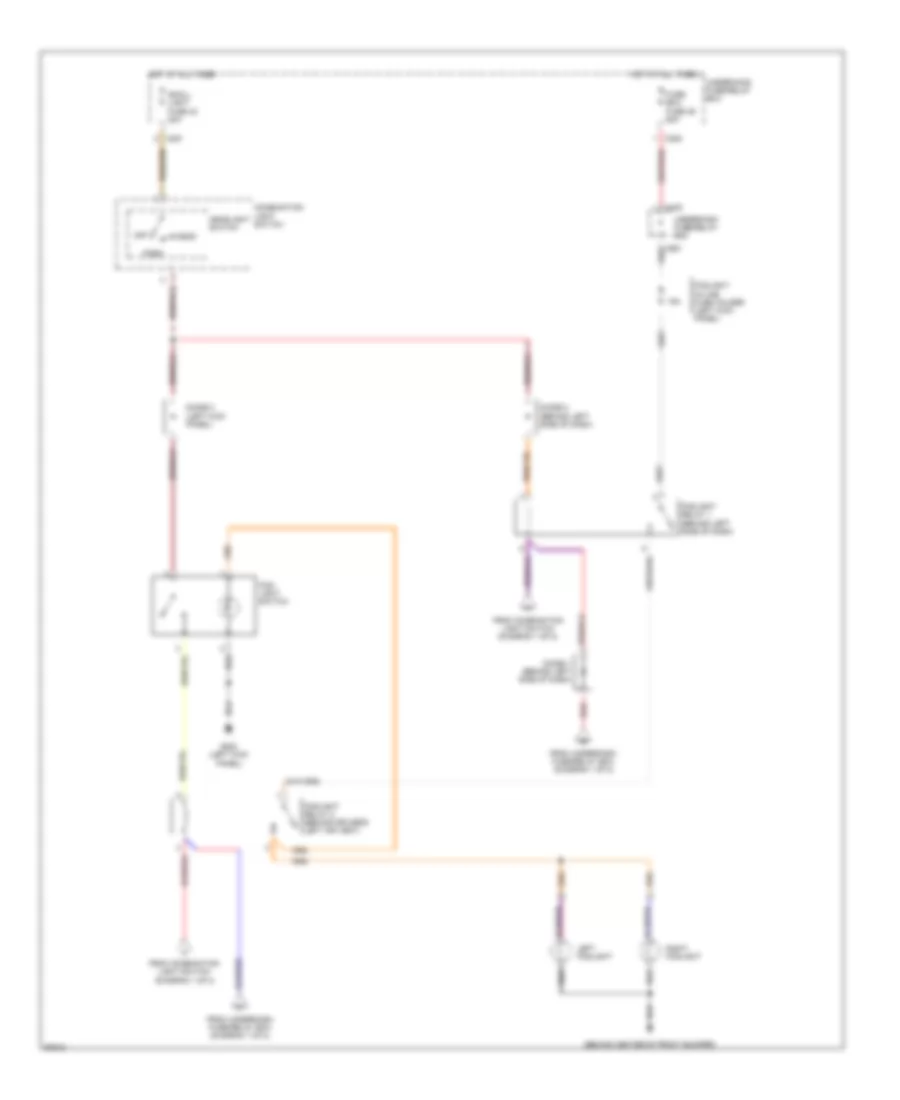
Headlight Wiring Diagram, without DRL (2 of 2) for Honda Prelude 1997
List of elements for Headlight Wiring Diagram, without DRL (2 of 2) for Honda Prelude 1997:
- (behind center of front bumper)
- 15a
- C251
- C254
- C435
- Combination light switch
- Diode 1 (behind left side of dash)
- Diode 2 (behind left side of dash)
- Diode 3 (left kick panel)
- Fog- light switch
- Foglight in-line fuse holder (left kick panel)
- Foglight relay 1 (behind left side of dash)
- Foglight relay 2 (behind driver's left air vent)
- From combination light switch (diagram 1 of 2)
- From underdash fuse/relay box (diagram 1 of 2)
- Fuse box fuse 36 50a
- G200 (left kick panel)
- Head
- Headlight switch
- Hot at all times
- Left foglight
- Off
- Park
- Red
- Right foglight
- Small light fuse 42 20a
- Underdash fuse/relay box
- Underhood fuse/relay box
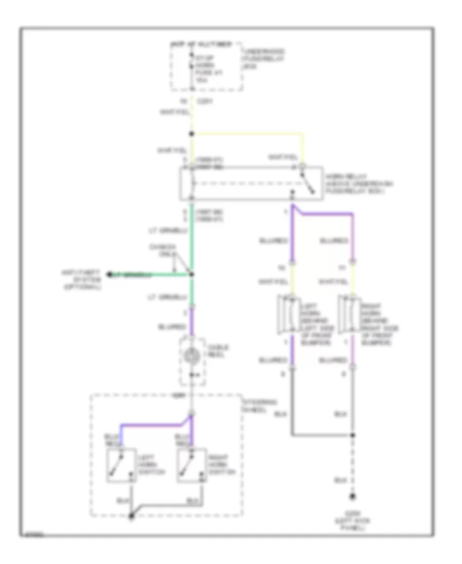
HORN
Horn Wiring Diagram for Honda Prelude 1997
List of elements for Horn Wiring Diagram for Honda Prelude 1997:
- (1997-98) (1999-01)
- (1999-01) (1997-98)
- Anti-theft system (optional)
- C251
- Cable reel
- Canada only
- G200 (left kick panel)
- Horn relay (above underdash fuse/relay box)
- Hot at all times
- Left horn (behind left side of front bumper)
- Left horn switch
- Right horn (behind right side of front bumper)
- Right horn switch
- Steering wheel
- Stop horn fuse 41 15a
- Underhood fuse/relay box
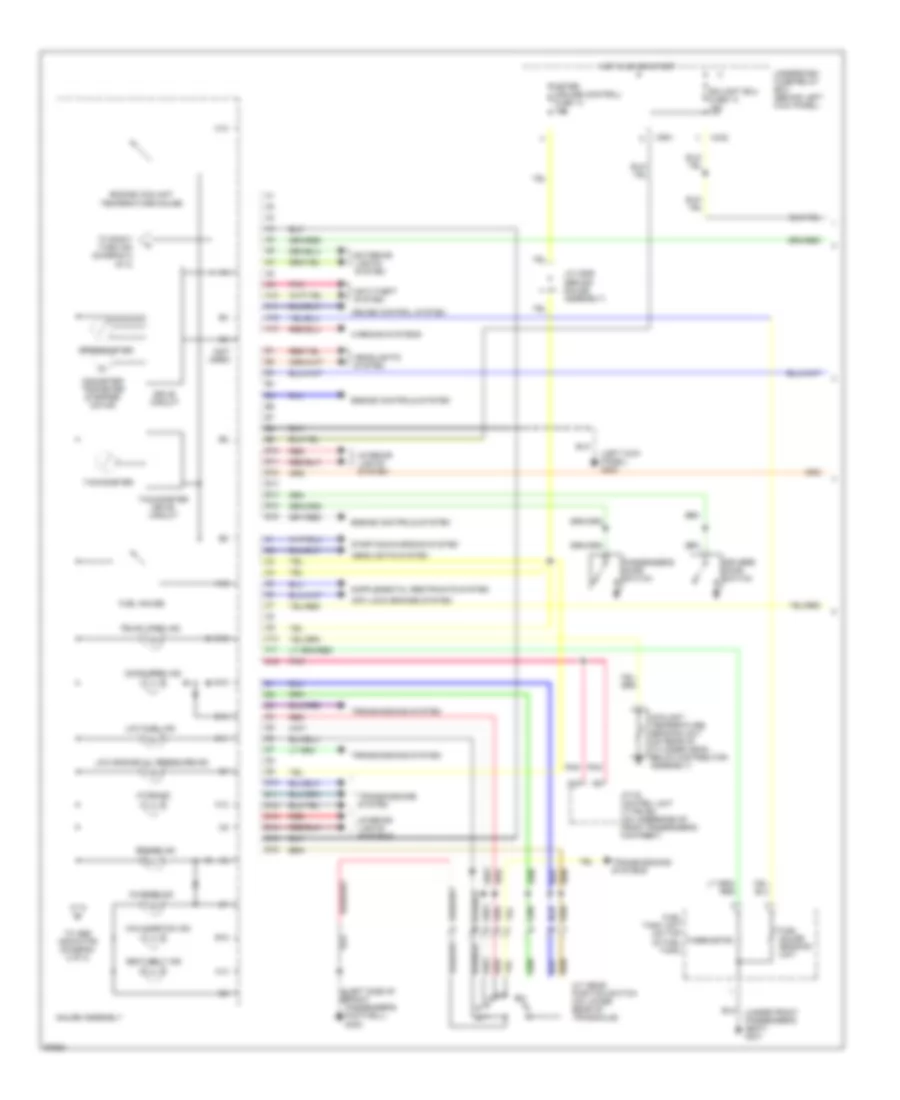
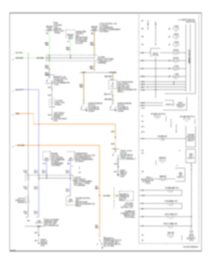
INSTRUMENT CLUSTER
Instrument Cluster Wiring Diagram (1 of 2) for Honda Prelude 1997
List of elements for Instrument Cluster Wiring Diagram (1 of 2) for Honda Prelude 1997:
- (left kick panel) g200
- (not used)
- (under front passenger's seat) g301
- A/t gear position switch (on lower rear of transaxle)
- A10
- A11
- A12
- A13
- A23
- Anti-lock brakes system
- Anti-theft system
- Atts control unit (type sh) (on underside of front passenger's footrest)
- Atts ind
- B10
- B11
- B12
- B13
- B14
- B15
- B16
- Brake ind
- C10
- C11
- C12
- C432
- C551
- Charge ind
- Coolant temperature sending unit (on rear of cylinder head, below distributor assembly)
- Cruise control system
- D10
- D11
- D12
- D13
- D14
- D15
- D16
- Door open ind
- Drive circuit
- Driver's door switch
- Ecu eat ecu fuse 14 15a
- Engine controls system
- Engine coolant temperature gauge
- Exterior lights system
- Footwell) g302
- Fuel gauge
- Fuel gauge sending unit
- Fuel tank unit (on top of fuel tank)
- Gauge assembly
- Headlights system
- Hot in on or start
- Interior lights system
- Interior lights systems
- J/c c559 (behind gauge assembly)
- Low engine oil pressure ind
- Low fuel ind
- Malfunction ind
- Meter (cruise control) fuse 13 15a
- Odometer/ tripmeter stepper motor
- Passenger's door switch
- Pnk
- Red
- Seat belt ind
- Speedometer
- Starting/charging system
- Tachometer
- Tachometer drive circuit
- Thermistor
- To abs indicator (diagram 2 of 2)
- To right turn ind (diagram 2 of 2)
- Transmissions system
- Transmissions systems
- Trunk open ind
- Underdash fuse/relay box (behind left kick panel)
- Warning systems
Instrument Cluster Wiring Diagram (2 of 2) for Honda Prelude 1997
List of elements for Instrument Cluster Wiring Diagram (2 of 2) for Honda Prelude 1997:
- (left front corner of engine compartment) g100
- (right rear of trunk) g405
- (right side of engine) g120
- 1 ind
- 2 ind
- A/t
- A/t gear position indicator
- A10
- A11
- Abs control unit (behind right kick panel)
- Abs ind
- Abs ind circuit
- Atts control unit (type sh) (on underside of front passenger's footrest)
- B10
- B11
- Brake fluid level switch (in brake fluid reservoir cap)
- Brake/ park input
- C18
- Canada
- Cruise control dimming circuit
- Cruise control unit (behind dash, above accelerator pedal)
- Cruise ind
- D10
- D11
- D12
- D13
- D14
- D15
- D16
- D3 ind
- D4 ind
- Daytime running lights (drl) control unit (behind dash, above accelerator pedal)
- Dimming circuit
- Display
- Driver's multiplex control unit
- Drl ind
- Engine control module (ecm) (on underside of front passenger's footrest)
- Engine oil pressure switch (on lower left of engine, below oil filter)
- Engine oil pressure switch input
- From brake ind b (diagram 1 of 2)
- From pin a4 (diagram 1 of 2)
- Gauge assembly
- Gauge lights (2)
- Gnd
- High beam ind
- Ign
- Immobilizer control unit (behind dash, on left side of steering column)
- Immobilizer ind
- J/c c117 (middle of engine)
- J/c c306 (left kick panel)
- J/c c456 (right kick panel, taped back to harness)
- J/c c479 (left side of front passenger's footwell, taped to harness)
- Left turn ind
- N ind
- P ind
- Parking brake switch (at base of park brake lever)
- R ind
- Right turn ind
- Shift indicator circuit
- Solid state
- Srs ind
- Srs ind circuit
- Transmission control module (tcm) (on underside of front passenger's footrest)
- Trunk latch switch (on center of trunk lid, at latch assembly)
- Underdash fuse/relay box (behind left kick panel)
- Usa
- Vehicle speed sensor (vss) (on top left of transaxle)
- Vss input
- Vss output
INTERIOR LIGHTS
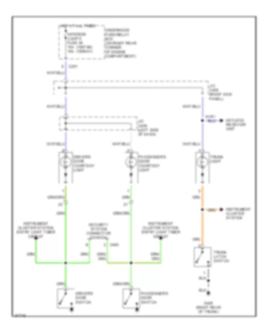
Courtesy Lamps Wiring Diagram for Honda Prelude 1997
List of elements for Courtesy Lamps Wiring Diagram for Honda Prelude 1997:
- (1997-98) (1999-01)
- C251
- C405
- Driver's door courtesy light
- Driver's door switch
- G405 (right rear of trunk)
- Hot at all times
- Instrument cluster system
- Instrument cluster system, entry light timer circuit
- Interior lights fuse 46 15a 10a
- J/c c406 (left side of dash)
- J/c c456 (right kick panel)
- Keyless receiver unit
- Passenger's door courtesy light
- Passenger's door switch
- Security system connector (canada)
- Trunk latch switch
- Trunk light
- Underhood fuse/relay box (on right rear corner of engine compartment)
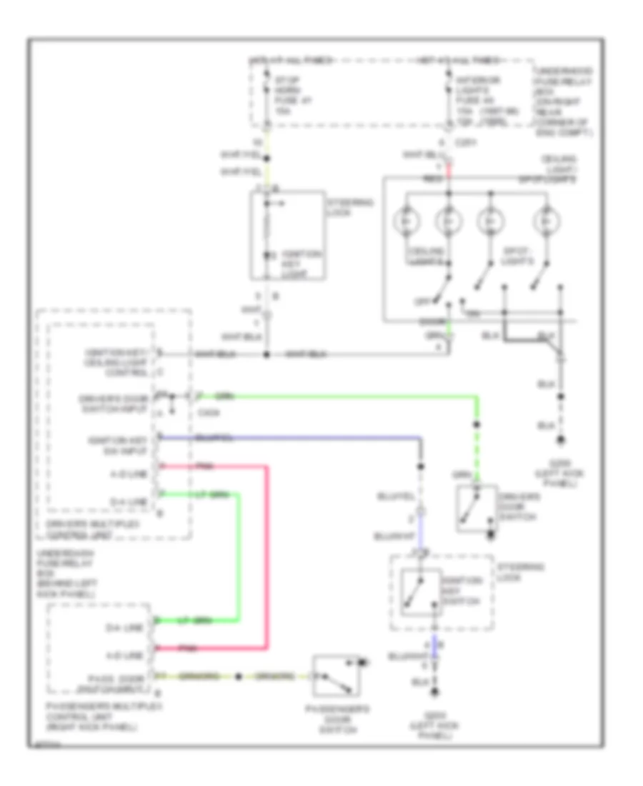
Entry Light Timer Wiring Diagram for Honda Prelude 1997
List of elements for Entry Light Timer Wiring Diagram for Honda Prelude 1997:
- (1997-98) (1999)
- A-d line
- C251
- C434
- Ceiling light/ spotlights
- Ceiling lights
- D-a line
- Door
- Driver's door switch
- Driver's door switch input a
- Driver's multiplex control unit
- G200 (left kick panel)
- Hot at all times
- Ignition key light
- Ignition key sw input
- Ignition key switch
- Ignition key/ ceiling light control
- Interior lights fuse 46 15a 10a
- Off
- Pass. door switch input
- Passenger's door switch
- Passenger's multiplex control unit (right kick panel)
- Pnk
- Red
- Spot- lights
- Steering lock
- Stop horn fuse 41 15a
- Underdash fuse/relay box (behind left kick panel)
- Underhood fuse/relay box (on right rear corner of eng compt)
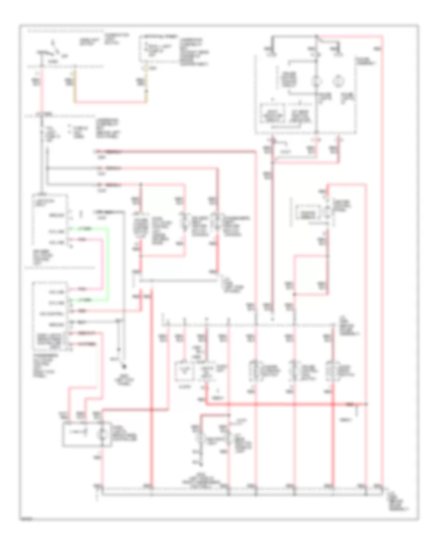
Instrument Illumination Wiring Diagram for Honda Prelude 1997
List of elements for Instrument Illumination Wiring Diagram for Honda Prelude 1997:
- (1997- 98)
- (1999-
- 01)
- 1999-01
- A-d line
- A/t gear position console light
- A/t gear position indicator
- Ashtray light
- Audio unit
- C251
- C431
- C433
- C434
- C551
- C980
- Clock
- Combination light switch
- Cruise control dimming circuit
- Cruise control main switch
- D-a line
- Dash lights brightness controller
- Dash lights brightness controller input
- Dim control
- Dimming circuit
- Door multiplex control unit (inside driver's door)
- Driver's multiplex control unit
- Driver's seat heater switch (canada)
- Fuse 20 (not used)
- G200 (left kick panel)
- G302 (left side of front passenger's footwell)
- Gauge assembly
- Gauge lights (2)
- Ground
- Hazard warning switch
- Head
- Headlight switch
- Heater control panel
- Hot at all times
- Illum in
- J/c c406 (left side of dash)
- J/c c559 (behind gauge assembly)
- Lights on input
- Lights on input
- Moon- roof switch
- Off
- Park
- Passenger's multiplex control unit (right kick panel)
- Passenger's seat heater switch (canada)
- Pnk
- Power window master switch illum
- Red
- Shift indicator circuit
- Small light fuse 42 20a
- Tail light fuse 10 15a
- Underdash fuse/relay box (behind left kick panel)
- Underhood fuse/relay box (on right rear corner of engine compartment)
- W/a/t
POWER DISTRIBUTION
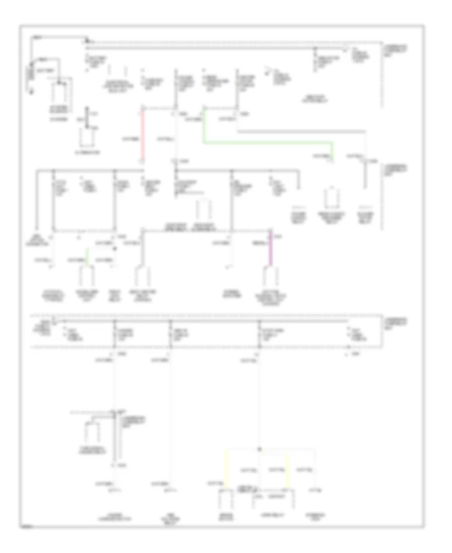
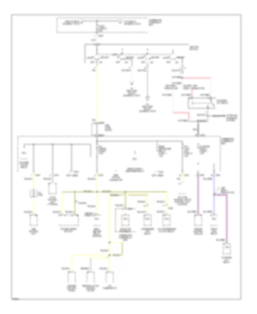
Power Distribution Wiring Diagram (1 of 5) for Honda Prelude 1997
List of elements for Power Distribution Wiring Diagram (1 of 5) for Honda Prelude 1997:
- (1997-98) (1999-01)
- (not used) fuse 3
- (not used) fuse 38
- (not used) fuse 49
- Abs +b fuse 40 20a
- Abs fail-safe relay
- Abs motor fuse 31 30a
- Abs pump motor relay
- Acg-s fuse 4 10a
- Alternator
- Atts fail- safe relay (type sh)
- Atts unit fuse 1 10a
- Battery
- Battery fuse 32 100a
- Blower motor relay
- Brake switch
- C251
- C252
- C253
- C254
- C431
- C432
- C434
- C435
- C436
- C437
- C981 option connector
- Coil contact
- Day light fuse 8 7.5a
- Daytime running lights control unit (canada)
- Electrical load detector (eld) unit
- From a fuse 31 (diagram 1 of 5)
- Fuse box fuse 36 50a
- Hazard fuse 39 10a
- Hazard warning switch
- Heated seat fuse 6 15a
- Heater motor fuse 35 40a
- Horn relay
- Immobilizer control unit
- Moon roof close relay
- Moon roof open relay
- Pgm-fi main relay
- Power window fuse 37 40a
- Power window relay
- Rear defroster fuse 34 40a
- Rear window defogger relay
- Rr speaker fuse 5 10a
- Seat heater relay (canada)
- Starter
- Starter solenoid
- Steering lock
- Stereo amplifier
- Stop horn fuse 41 15a
- Sun roof fuse 7 30a
- T101
- T102
- To fuse 33 (diagram 2 of 5)
- To fuse 38 (diagram 1 of 5)
- Turn signal/ hazard relay
- Underdash fuse/relay box
- Underhood fuse/relay box
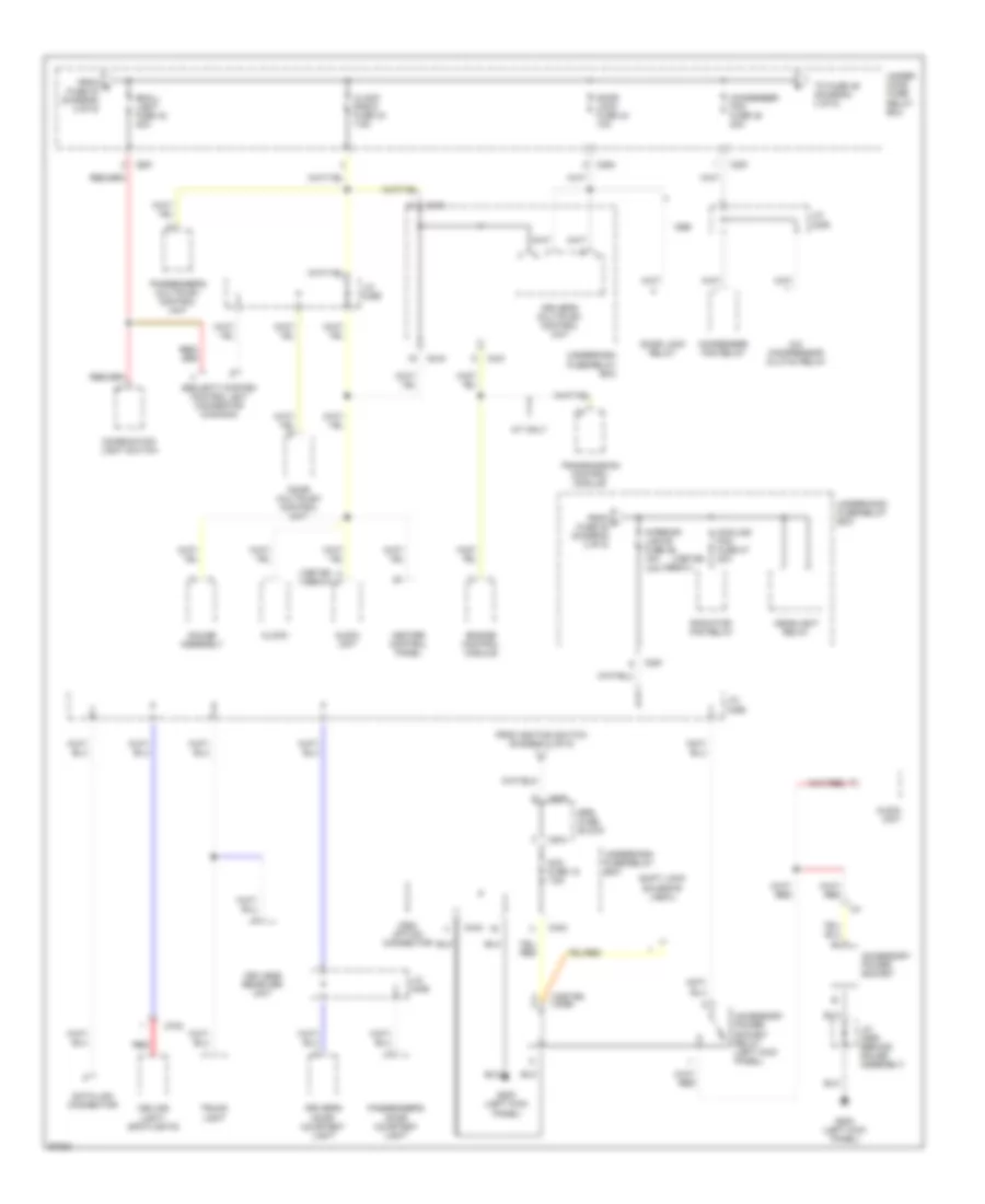
Power Distribution Wiring Diagram (2 of 5) for Honda Prelude 1997
List of elements for Power Distribution Wiring Diagram (2 of 5) for Honda Prelude 1997:
- (1997-98) (1999-01)
- (not used)
- 1997 early production
- A/c compressor clutch relay
- A/c thermostat
- Abs control unit
- Acc
- Atts control unit (type sh)
- Blower motor relay
- C252
- C253
- C302
- C432
- C433
- C434
- C437
- C438
- C551
- C974
- C976
- C982 option connector
- Canada
- Coil
- Condenser fan relay
- Day light unit fuse 12 7.5a
- Daytime running lights control unit (canada)
- Early production
- Engine control module
- Except 1997 early production
- From fuse 35 b (diagram 1 of 5)
- Heater control panel
- Ig sw fuse 33 50a
- Ignition switch
- J/c c456
- Lock
- Nca
- Pgm-fi main relay
- Power mirror switch
- R/c mirror fuse 9 7.5a
- Radiator fan relay
- Rear defroster relay fuse 11 7.5a
- Rear window defogger relay
- Recirculation control motor
- Seat heater relay (canada)
- Srs fuse block
- Start
- Starter cut relay
- Starter signal fuse 2 7.5a
- Starting/ charging system
- To fuse 42 (diagram 3 0f 5)
- To srs fuse block (diagram 3 of 5)
- To srs fuse block (diagram 4 of 5)
- Underdash fuse/relay box
- Underhood fuse/relay box
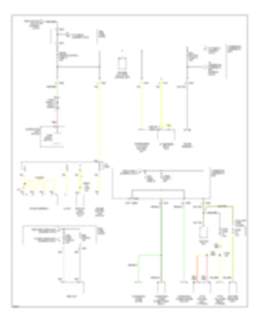
Power Distribution Wiring Diagram (3 of 5) for Honda Prelude 1997
List of elements for Power Distribution Wiring Diagram (3 of 5) for Honda Prelude 1997:
- (1997-98)
- (1997-98) (1999)
- (1997-98) (1999-01)
- (1999-01)
- A/c compressor clutch relay
- A/t only
- Acc fuse 18 7.5a
- Accessory power socket
- Accessory power socket relay (left kick panel)
- Audio unit
- C251
- C254
- C431
- C433
- C434
- C702
- C974
- C976
- C984 option connector
- Ceiling light/ spotlights
- Clock
- Clock radio fuse 43 7.5a
- Combination light switch
- Condenser fan fuse 45 20a
- Condenser fan relay
- Cooling fan fuse 47 20a
- Data link connector
- Door lock fuse 44 10a
- Door lock relay
- Door multiplex control unit
- Driver's door courtesy light
- Driver's multiplex control unit
- Engine control module
- From e fuse 33 (diagram 2 of 5)
- From f fuse 45 (diagram 3 of 5)
- From ignition switch (diagram 2 of 5)
- G200 (left kick panel)
- Gauge assembly
- Headlight relay
- Heater control panel
- Interior lights fuse 46 15a 10a
- J/c c306
- J/c c406
- J/c c456
- J/c c559 (behind gauge assembly)
- Keyless receiver unit
- Passenger's door courtesy light
- Passenger's multiplex control unit
- Radiator fan relay
- Red
- Security system control unit connector (canada)
- Shift lock solenoid (a/t)
- Small light fuse 42 20a
- Srs fuse block
- To fuse 46 (diagram 3 of 5)
- Transmission control module
- Trunk light
- Under- hood fuse/ relay box
- Underdash fuse/relay box
- Underhood fuse/relay box
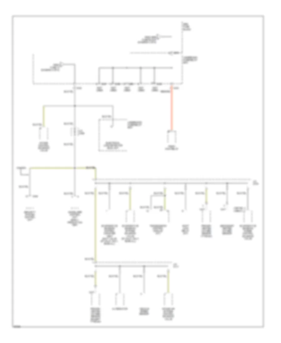
Power Distribution Wiring Diagram (4 of 5) for Honda Prelude 1997
List of elements for Power Distribution Wiring Diagram (4 of 5) for Honda Prelude 1997:
- from ignition switch (diagram 2 of 5)
- (1997-98) (1999-01)
- (not used)
- (not used) fuse 19
- 1999-01 & type sh
- A/t
- A/t reverse relay (a/t)
- Atts control unit (type sh)
- Atts fail-safe relay (type sh)
- Atts fuse 7.5a
- Auxiliary fuse holder
- Back-up light switch (m/t)
- C431
- C432
- C434
- C435
- C436
- C551
- C801
- C974
- C976
- C980
- Canada
- Clock
- Combination light switch
- Cruise control main switch
- Driver's multiplex control unit
- Ecu eat ecu fuse 14 15a
- From fuse 14 h (diagram 4 of 5)
- From srs fuse block g (diagram 4 of 5)
- Fuel pump fuse 23 15a
- Fuse 10a
- Gauge assembly
- Ignition coil
- J/c c559
- Keyless receiver unit
- Meter (cruise control) fuse 13 15a
- Passenger's multiplex control unit
- Red
- Srs fuse 24 10a
- Srs fuse block
- Srs unit
- To fuse 19 (diagram 4 of 5)
- To fuse 23 (diagram 4 of 5)
- To srs fuse block (diagram 5 of 5)
- To underdash fuse/relay box (diagram 5 of 5)
- Turn signal light diode
- Turn signal switch
- Type sh
- Underdash fuse/relay box
- Windshield wiper intermittent relay
- Windshield wiper motor
- Windshield wiper/washer switch
- Wiper fuse 17 30a
Power Distribution Wiring Diagram (5 of 5) for Honda Prelude 1997
List of elements for Power Distribution Wiring Diagram (5 of 5) for Honda Prelude 1997:
- (1997-98) (1999-01)
- (not used)
- Alternator
- C405
- C432
- C433
- C437
- C438
- C551
- C974
- Canada
- Electrical load detector (eld) unit
- Evaporative emission bypass solenoid valve (97 calif. only, 98-99 all)
- Evaporative emission control canister vent shut valve (97 calif. only, 98-99 all)
- Evaporative emission purge control solenoid valve
- From i fuse 14 (diagram 4 of 5)
- From srs j fuse block (diagram 4 of 5)
- Immobilizer control unit (early production 1997)
- Intake air bypass control solenoid valve
- Intake control solenoid valve
- J/c c117
- J/c c456
- J/c c479
- Pgm-fi main relay
- Primary heated oxygen sensor (except type sh)
- Primary heated oxygen sensor (type sh)
- Secondary heated oxygen sensor
- Security system control unit
- Shift lock relay (a/t)
- Srs fuse block
- Transmission control module (a/t)
- Underdash fuse/relay box
- Underhood fuse/relay box
- Vehicle speed sensor
POWER DOOR LOCKS
Power Door Lock Wiring Diagram for Honda Prelude 1997
List of elements for Power Door Lock Wiring Diagram for Honda Prelude 1997:
- (canada)
- A-d line
- Battery input
- Battery input (door lock)
- C405 c407
- Clock radio fuse 43 7.5a
- D-a line
- Door d-line
- Door lock fuse 44 10a
- Door multiplex control unit (in driver's door)
- Driver's door key cyl sw input
- Driver's door key cylinder switch
- Driver's door lock actuator
- Driver's door lock assembly
- Driver's door lock knob sw lock input
- Driver's door lock knob sw unlock input
- Driver's door lock sw lock input
- Driver's door lock sw unlock input
- Driver's door lock switch
- Driver's multiplex control unit
- G200 (left kick panel)
- G203 (right kick panel)
- Ground (door lock)
- Hot at all times
- J/c c406 (behind left side of dash)
- J/c c456 (right kick panel)
- Knob switch
- Lock
- Passenger's door key cylinder switch
- Passenger's door lock actuator
- Passenger's door lock switch
- Passenger's multiplex control unit (behind right kick panel)
- Pnk
- Security system connector (option)
- Under-dash fuse/relay box
- Under-hood fuse/relay box
- Unlock
POWER MIRRORS
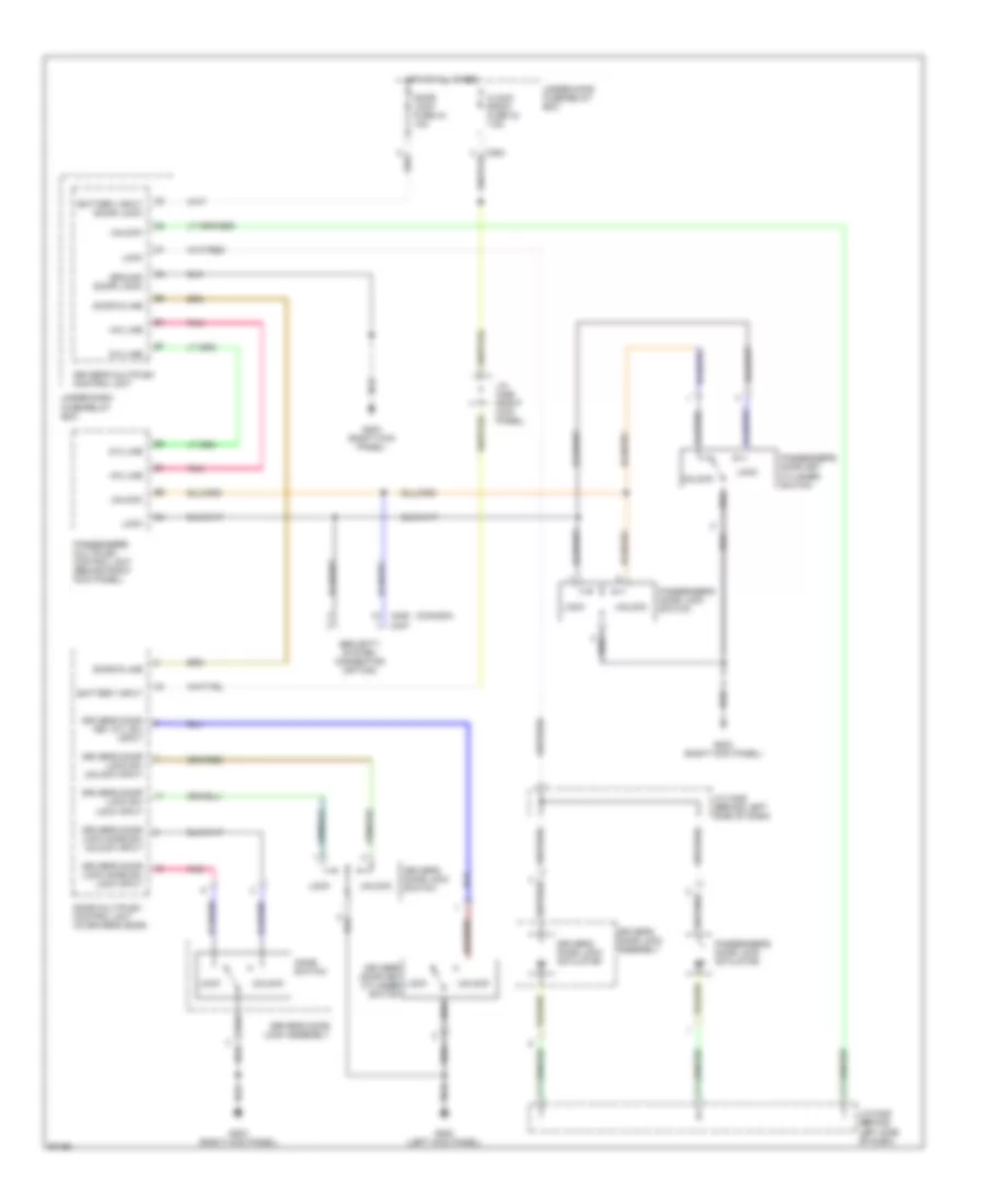
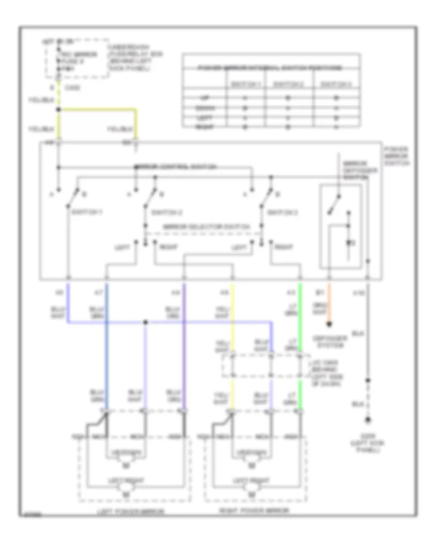
Power Mirror Wiring Diagram, Canada for Honda Prelude 1997
List of elements for Power Mirror Wiring Diagram, Canada for Honda Prelude 1997:
- A10
- C432
- Defogger system
- Down
- G200 (left kick panel)
- Hot in on
- J/c c406 (behind left side of dash)
- Left
- Left power mirror
- Left/right
- Mirror control switch
- Mirror defogger switch
- Mirror selector switch
- Nca
- Power mirror internal switch positions
- Power mirror switch
- R/c mirror fuse 9 7.5a
- Right
- Right power mirror
- Switch 1
- Switch 2
- Switch 3
- Underdash fuse/relay box (behind left kick panel)
- Up/down
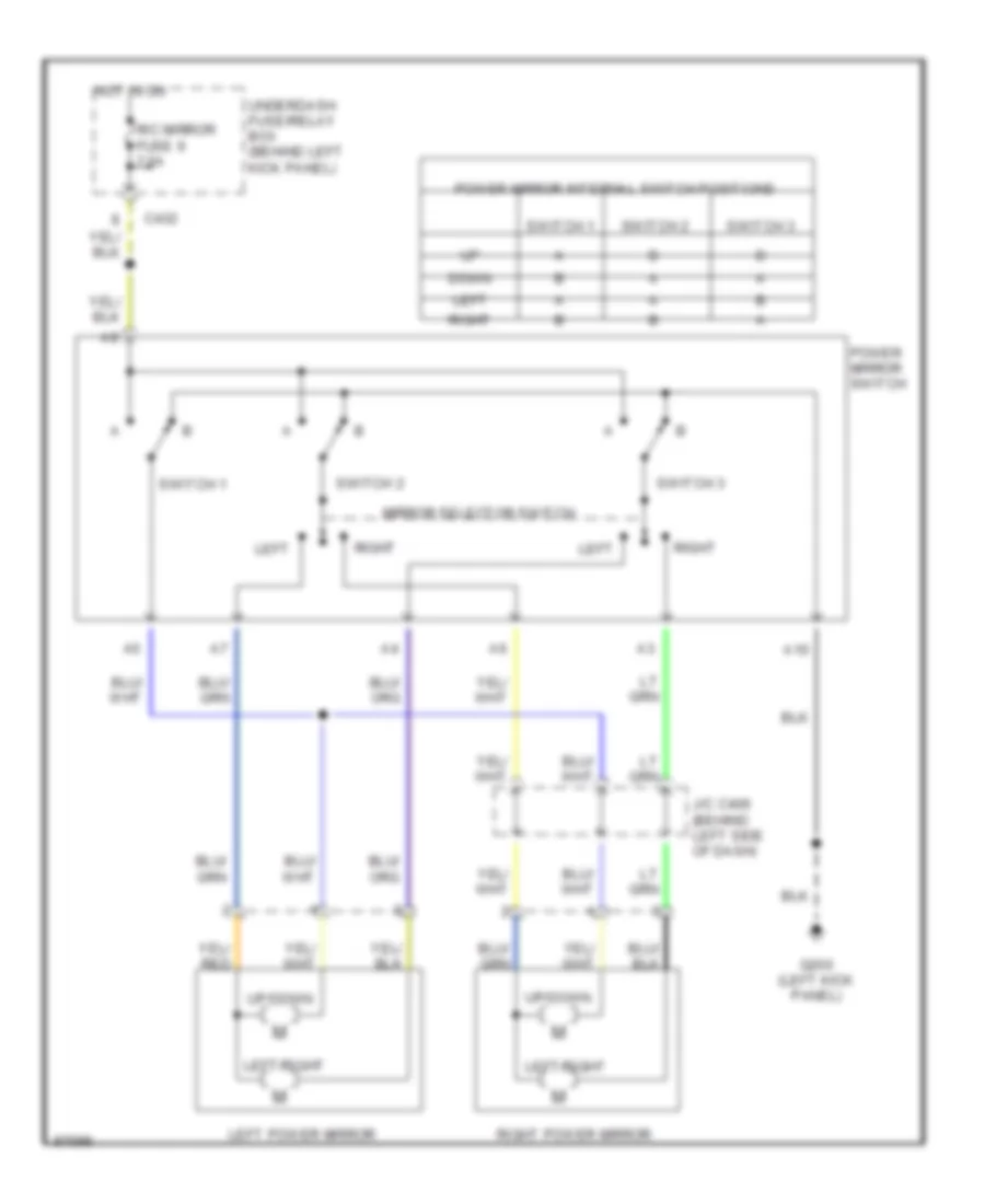
Power Mirror Wiring Diagram, USA for Honda Prelude 1997
List of elements for Power Mirror Wiring Diagram, USA for Honda Prelude 1997:
- A10
- C432
- Down
- G200 (left kick panel)
- Hot in on
- J/c c406 (behind left side of dash)
- Left
- Left power mirror
- Left/right
- Mirror selector switch
- Power mirror internal switch positions
- Power mirror switch
- R/c mirror fuse 9 7.5a
- Right
- Right power mirror
- Switch 1
- Switch 2
- Switch 3
- Underdash fuse/relay box (behind left kick panel)
- Up/down
POWER SEATS
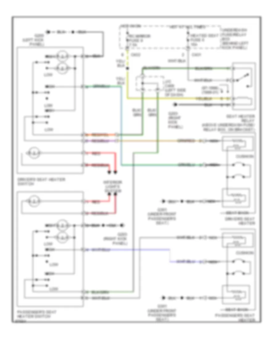
Heated Seats Wiring Diagram for Honda Prelude 1997
List of elements for Heated Seats Wiring Diagram for Honda Prelude 1997:
- (97-1998) (1999-01)
- C431
- C432
- Cushion
- Driver's seat heater
- Driver's seat heater switch
- G200 (left kick panel)
- G203 (right kick panel)
- G301 (under front passenger's seat)
- Heated seat fuse 6 15a
- High
- Hot at all times
- Hot in on
- Interior lights system
- J/c c406 (left side of dash)
- Low
- Nca
- Passenger's seat heater
- Passenger's seat heater switch
- Rc mirror fuse 9 7.5a
- Red
- Seat heater relay (above underdash fuse/ relay box, on bracket)
- Seat-back
- Underdash fuse/relay box (behind left kick panel)
POWER TOP/SUNROOF
Moonroof Wiring Diagram for Honda Prelude 1997
List of elements for Moonroof Wiring Diagram for Honda Prelude 1997:
- (left kick panel) g200
- (not used)
- A-d line
- A13
- A14
- Battery
- Battery input
- C254
- C431
- C432
- C433
- C434
- C435
- C551
- Clock radio fuse 43 7.5a
- Close
- D-a line
- D11
- Driver's door switch
- Driver's door switch input
- Driver's multiplex control unit
- Hot at all times
- Hot in on or start
- Ignition
- Ignition input
- Interior lights system
- Meter (cruise control) fuse 13 15a
- Moon roof close relay
- Moon roof motor (on rear underside of ceiling)
- Moon roof open relay
- Moonroof switch
- Open
- Passenger's door switch
- Passenger's door switch input
- Passenger's multiplex control unit (behind right kick panel)
- Pnk
- Power window fuse 37 40a
- Power window relay
- Power window relay control
- Red
- Sun roof fuse 7 30a
- Underdash fuse/relay box (behind left kick panel)
- Underhood fuse/relay box (on right rear corner of engine compartment)
POWER WINDOWS
Power Window Wiring Diagram (1 of 2) for Honda Prelude 1997
List of elements for Power Window Wiring Diagram (1 of 2) for Honda Prelude 1997:
- (left kick panel)
- (not used)
- A-d line
- A11
- A12
- A13
- A14
- A20
- B11
- Batt in
- C254
- C405
- C432
- C433
- C434
- C551
- Clock radio fuse 43 7.5a
- D-a line
- Door d-line
- Down
- Driver's door sw input
- Driver's door switch
- Driver's multiplex control unit
- G200
- G200 (left kick panel)
- Grd
- Ground
- Hot at all times
- Hot in on or start
- Ign in
- Interior lights system
- Main sw input
- Meter (cruise control) fuse 13 15a
- Off
- Pass door sw input
- Pass pwr wdo mtr ctrl
- Passenger's door switch
- Passenger's multiplex control unit (behind right kick panel)
- Passenger's power window motor
- Passenger's window switch
- Pnk
- Power window fuse 37 40a
- Pwr wdo rly input
- Security system connector (canada)
- Underdash fuse/relay box
- Underhood fuse/relay box
Power Window Wiring Diagram (2 of 2) for Honda Prelude 1997
List of elements for Power Window Wiring Diagram (2 of 2) for Honda Prelude 1997:
- (not used)
- Auto dn
- Batt input
- C431
- C433
- C434
- C435
- C551
- Control unit
- Door d-line
- Door multiplex control unit (in driver's door)
- Driver's multiplex control unit
- Driver's switch
- Driver's window motor
- G200 (left kick panel)
- G203 (right kick panel)
- Interior lights system
- J/c c456 (right kick panel)
- Main switch
- P/w assistant fuse 16 20a
- P/w driver fuse 15 20a
- Passenger's switch
- Power window master switch
- Power window master switch light
- Power window relay
- Pwr wdo rly ctrl
- Red
- Underdash fuse/relay box
RADIO
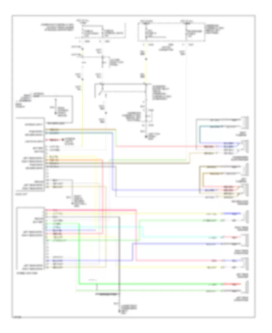
Radio Wiring Diagrams for Honda Prelude 1997
List of elements for Radio Wiring Diagrams for Honda Prelude 1997:
- (left kick panel) g200
- (option connector)
- (right side of driver's footwell) g202
- (under front passenger's seat) g301
- Acc fuse 18 7.5a
- Accessory socket relay (above underdash fuse/relay box, on bracket)
- Antenna input
- Antenna lead
- Audio unit
- Battery
- Braided wire
- C251
- C254
- C431
- C433
- C434
- C984
- Driver's door speaker
- Driver's spkr +
- Driver's spkr -
- Fuse 43 clock radio 7.5a
- Fuse 46 interior lights 15a
- Ground
- Hot at all times
- Hot in acc or on
- Ignition
- Interior lights system
- J/c c456 (right kick panel)
- Left rear microphone
- Left rear speaker
- Left rear spkr +
- Left rear spkr -
- Left tweeter
- Lights on input
- Nca
- Pass spkr +
- Pass spkr -
- Passenger's door speaker
- Pnk
- Radio antenna shield ground
- Rear window
- Rear window antenna
- Red
- Right rear microphone
- Right rear speaker
- Right rear spkr +
- Right rear spkr -
- Right tweeter
- Rr speaker fuse 5 10a
- Stereo amplifier
- Underdash fuse/relay box (behind left kick panel)
- Underhood fuse/relay box (on right rear corner of engine compartment)
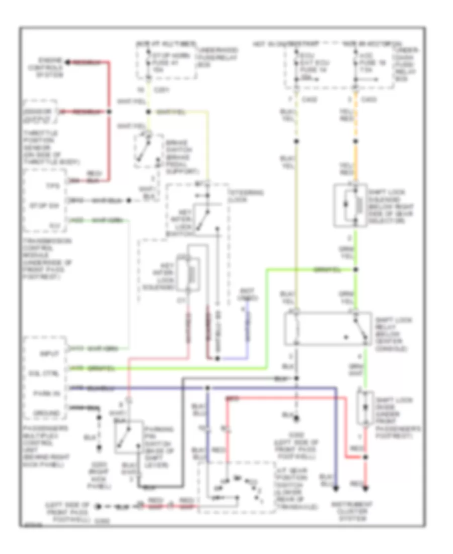
SHIFT INTERLOCKS
Shift Interlock Wiring Diagram for Honda Prelude 1997
List of elements for Shift Interlock Wiring Diagram for Honda Prelude 1997:
- (left side of front pass. footwell)
- (not used)
- A/t gear position switch (lower rear of transaxle)
- A13
- A14
- A15
- A16
- A22
- Acc fuse 18 7.5a
- B12
- Brake switch (brake pedal support)
- C251
- C432
- C433
- Ecu eat ecu fuse 14 15a
- Engine controls system
- G203 (right kick panel)
- G302
- G302 (left side of front pass. footwell)
- Ground
- Hot at all times
- Hot in acc or on
- Hot in on or start
- Ilu
- Input
- Instrument cluster system
- Key inter- lock solenoid
- Key inter- lock switch
- Park in
- Parking pin switch (base of shift lever)
- Passenger's multiplex control unit (behind right kick panel)
- Red
- Sensor output
- Shift lock diode (under front passenger's footrest)
- Shift lock relay (below center console)
- Shift lock solenoid (below right side of gear selector)
- Sol ctrl
- Steering lock
- Stop horn fuse 41 15a
- Stop sw
- Throttle position sensor (on side of throttle body)
- Tps
- Transmission control module (underside of front pass. footrest)
- Under- dash fuse/ relay box
- Underhood fuse/relay box
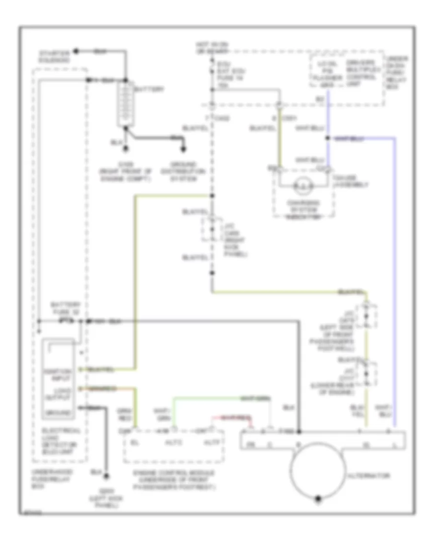
STARTING/CHARGING
Charging Wiring Diagram for Honda Prelude 1997
List of elements for Charging Wiring Diagram for Honda Prelude 1997:
- A19
- Altc
- Alternator
- Altf
- Battery
- Battery fuse 32 100a
- C17
- C432
- C551
- Charging system indicator
- D16
- Driver's multiplex control unit
- Ecu eat ecu fuse 14 15a
- Electrical load detector (eld) unit
- Engine control module (underside of front passenger's footrest)
- G109 (right front of engine compt)
- G200 (left kick panel)
- Gauge assembly
- Ground
- Ground distribution system
- Hot in on or start
- Ignition input
- J/c c117 (lower rear of engine)
- J/c c456 (right kick panel)
- J/c c479 (left side of front passenger's footwell)
- Lo oil psi flasher ckt
- Load output
- Starter solenoid
- T101
- T102
- Under dash- fuse/ relay box
- Under-hood fuse/relay box
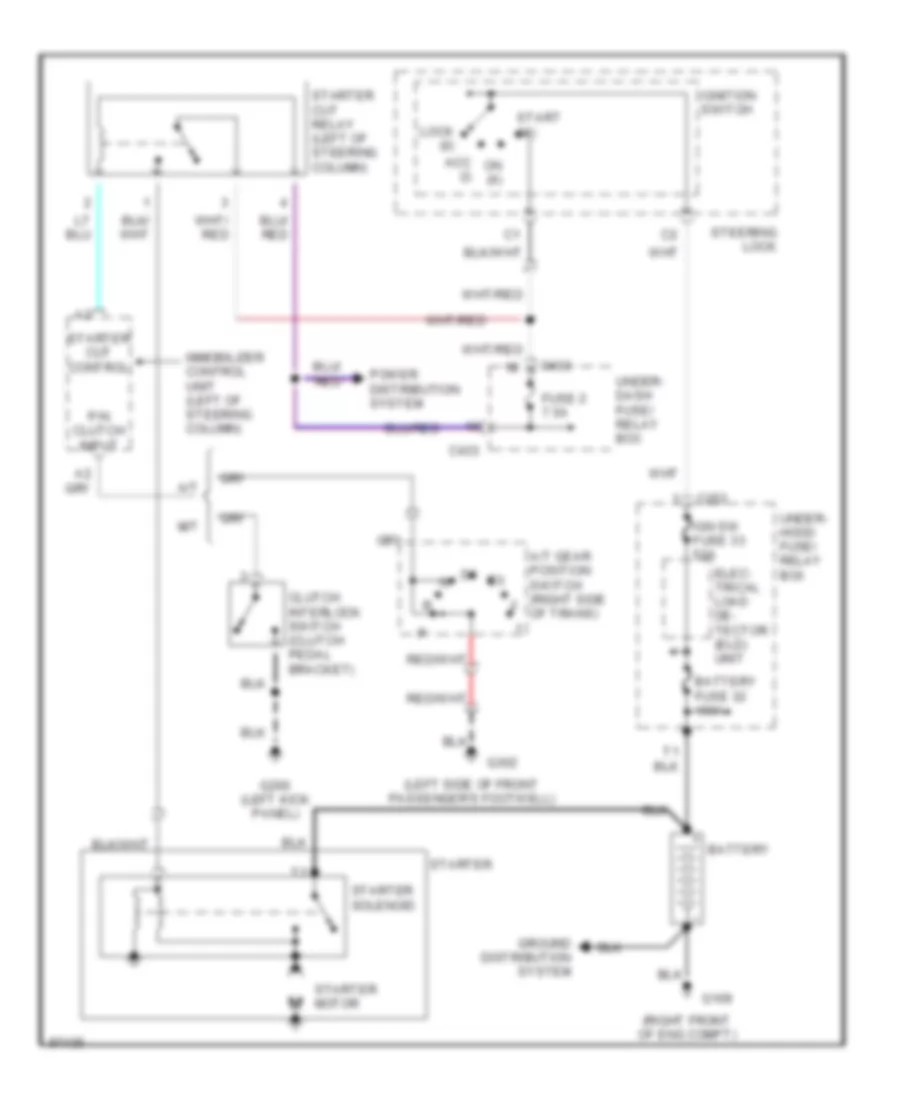
Starting Wiring Diagram, Early Production for Honda Prelude 1997
List of elements for Starting Wiring Diagram, Early Production for Honda Prelude 1997:
- (left side of front passenger's footwell)
- (right front of eng compt)
- A/t
- A/t gear position switch (right side of trans)
- Acc (i)
- Battery
- Battery fuse 32 100a
- C253
- C433
- Clutch interlock switch (clutch pedal bracket)
- Elec- trical load de- tector (eld) unit
- Fuse 2 7.5a
- G109
- G200 (left kick panel)
- G302
- Ground distribution system
- Ign sw fuse 33 50a
- Ignition switch
- Immobilizer control unit (left of steering column)
- Lock (0)
- M/t
- On (ii)
- P/n clutch input
- Power distribution system
- Start (iii)
- Starter
- Starter cut control
- Starter cut relay (left of steering column)
- Starter motor
- Starter solenoid
- Steering lock
- Under- dash fuse/ relay box
- Under- hood fuse/ relay box
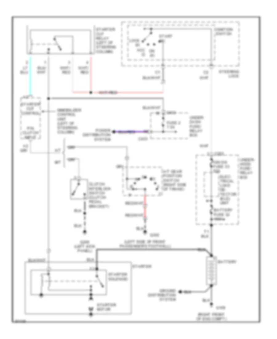
Starting Wiring Diagram, Late Production for Honda Prelude 1997
List of elements for Starting Wiring Diagram, Late Production for Honda Prelude 1997:
- (left side of front passenger's footwell)
- (right front of eng compt)
- A/t
- A/t gear position switch (right side of trans)
- Acc (i)
- Battery
- Battery fuse 32 100a
- C253
- C433
- Clutch interlock switch (clutch pedal bracket)
- Elec- trical load de- tector (eld) unit
- Fuse 2 7.5a
- G109
- G200 (left kick panel)
- G302
- Ground distribution system
- Ign sw fuse 33 50a
- Ignition switch
- Immobilizer control unit (left of steering column)
- Lock (0)
- M/t
- On (ii)
- P/n clutch input
- Power distribution system
- Start (iii)
- Starter
- Starter cut control
- Starter cut relay (left of steering column)
- Starter motor
- Starter solenoid
- Steering lock
- Under- dash fuse/ relay box
- Under- hood fuse/ relay box
SUPPLEMENTAL RESTRAINTS
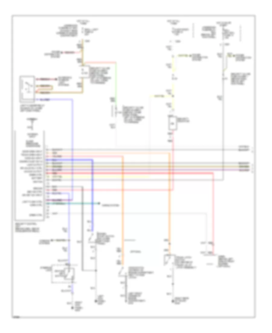
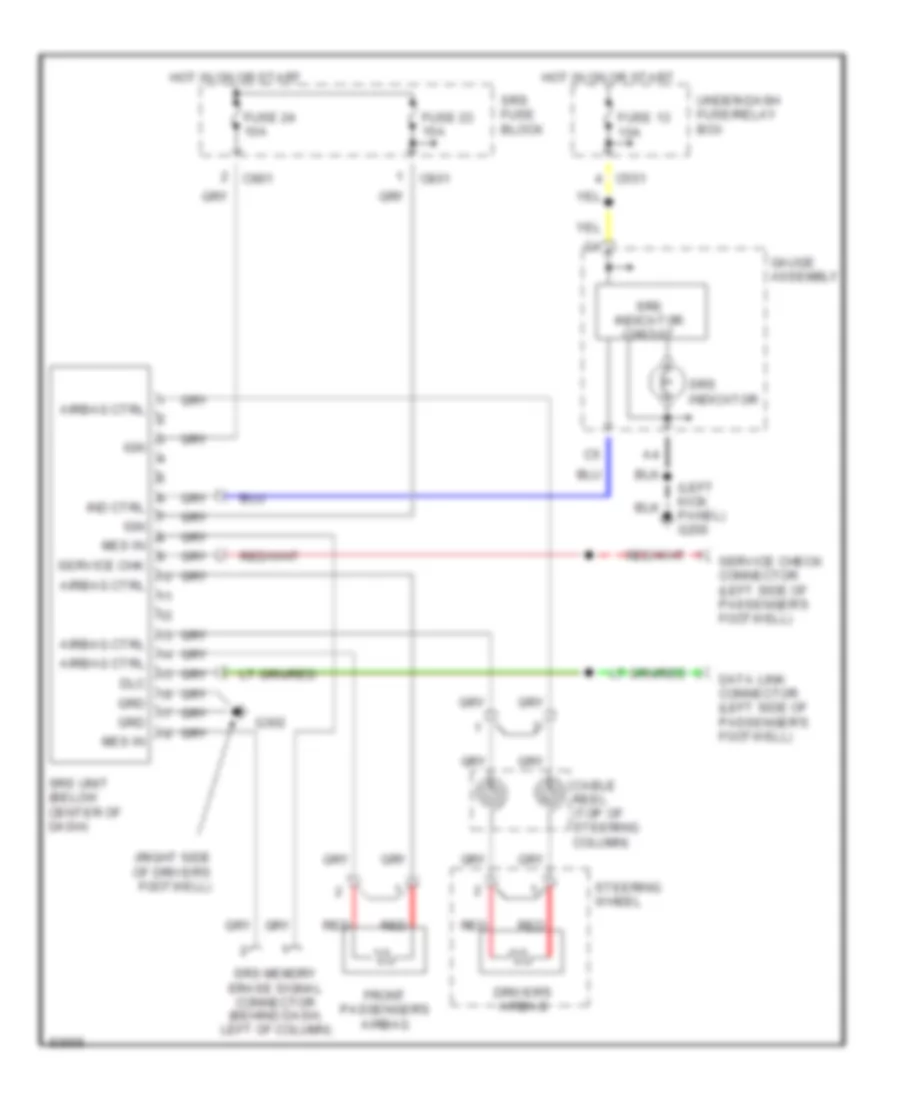
Supplemental Restraint Wiring Diagram for Honda Prelude 1997
List of elements for Supplemental Restraint Wiring Diagram for Honda Prelude 1997:
- (left kick panel) g200
- (right side of driver's footwell)
- Airbag ctrl
- C551
- C801
- Cable reel (top of steering column)
- Data link connector (left side of passenger's footwell)
- Dlc
- Driver's airbag
- Front passenger's airbag
- Fuse 13 10a
- Fuse 23 15a
- Fuse 24 10a
- G302
- Gauge assembly
- Grd
- Hot in on or start
- Ign
- Ind ctrl
- Mes in
- Red
- Service check connector (left side of passenger's footwell)
- Service chk
- Srs fuse block
- Srs indicator
- Srs indicator circuit
- Srs memory erase signal connector (behind dash, left of column)
- Srs unit (below center of dash)
- Steering wheel
- Under-dash fuse/relay box
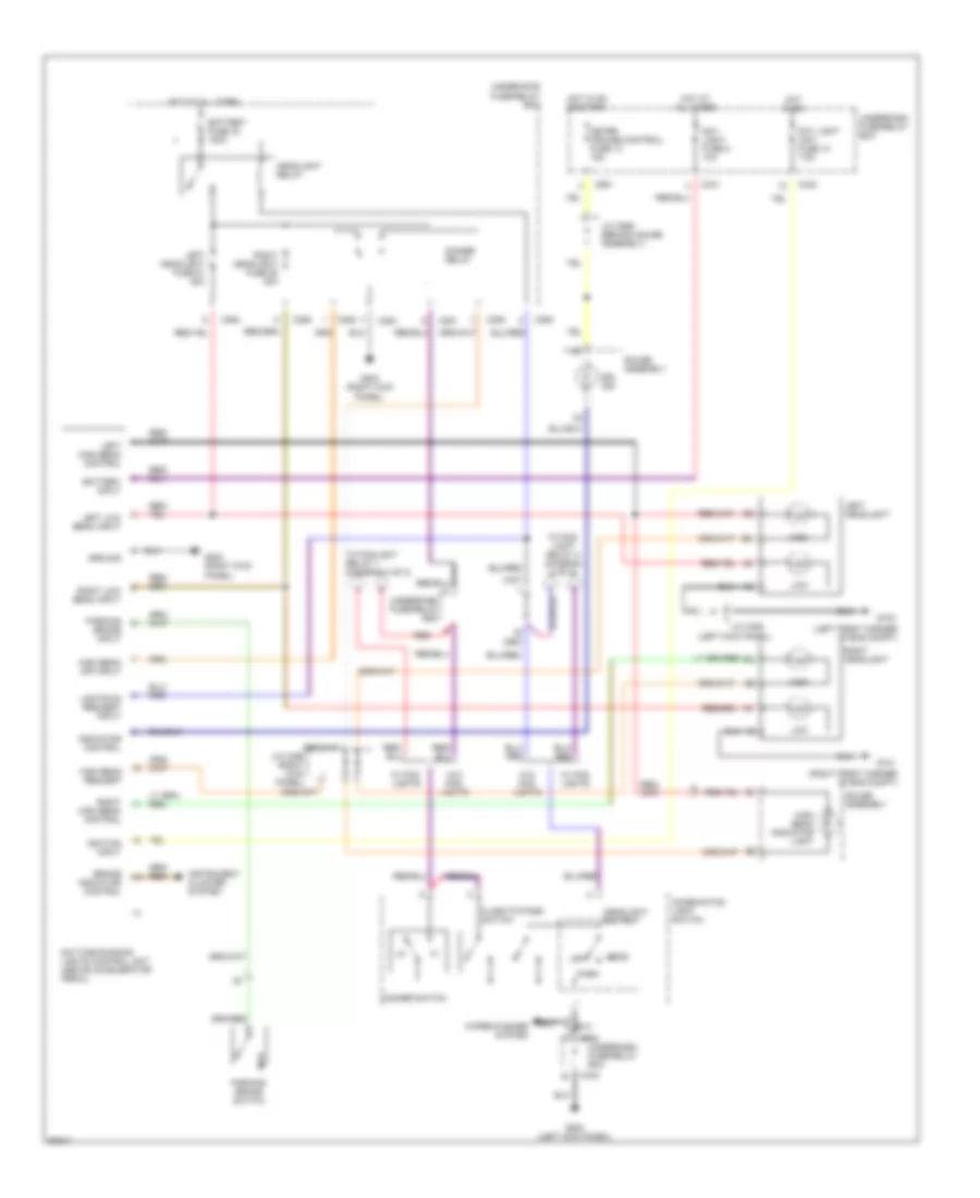
TRANSMISSION
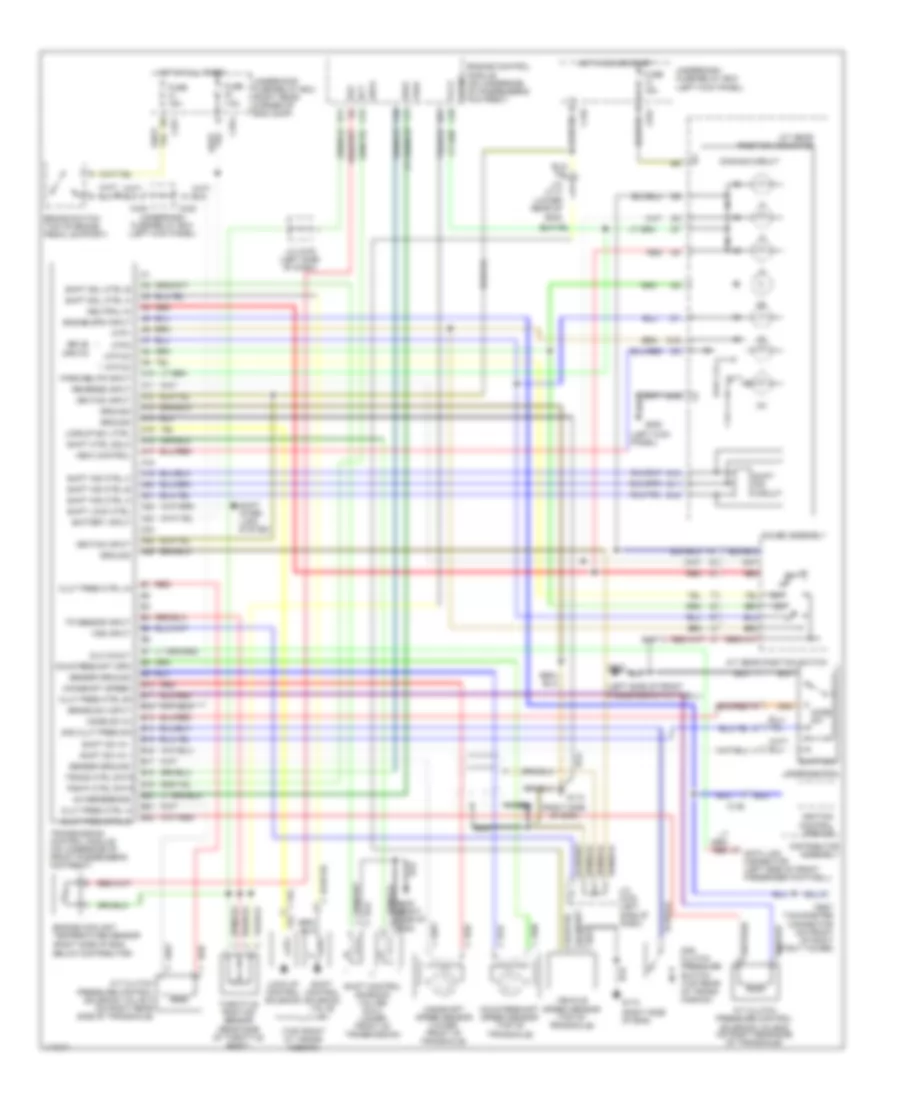
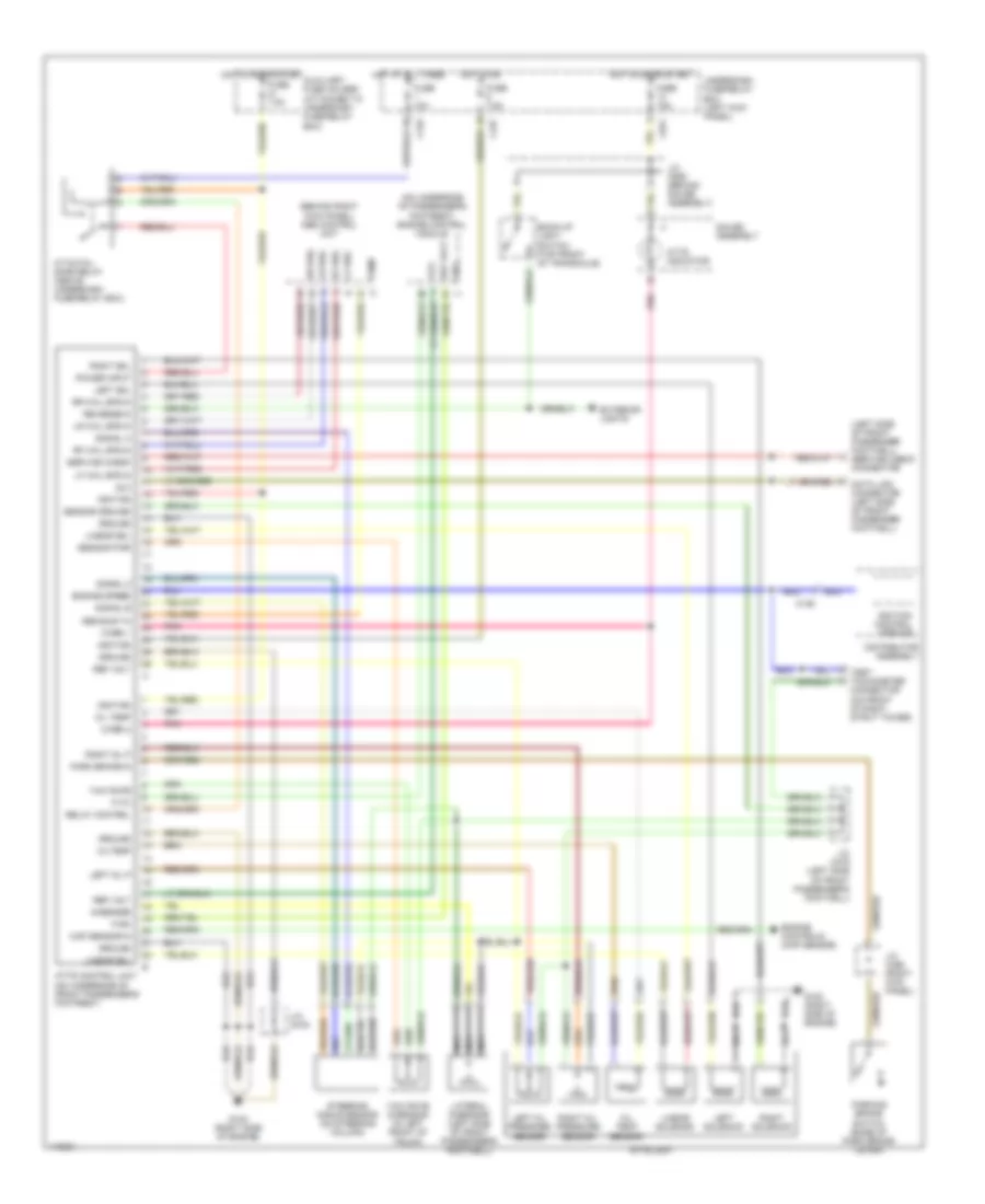
A/T Wiring Diagram for Honda Prelude 1997
List of elements for A/T Wiring Diagram for Honda Prelude 1997:
- (left kick panel)
- (left side of front passenger's footwell)
- (right side of eng)
- (top front ot trans- mission)
- +5v reference
- 2nd clut pres sw
- 2nd clutch pressure switch (top rear of trans- mission)
- A/t clutch pressure control solenoid valve a (on right rear side of transaxle)
- A/t clutch pressure control solenoid valve b (on right rear side of transaxle)
- A/t gear position indicator
- A/t gear position switch
- A10
- A11
- A12
- A13
- A14
- A15
- A16
- A17
- A18
- A19
- A20
- A21
- A22
- A23
- A24
- A25
- A26
- Atp d3
- Atp d4
- Atp1
- Atp2
- Atpnp
- B10
- B11
- B12
- B13
- B14
- B15
- B16
- B17
- B18
- B19
- B20
- B21
- B22
- Battery input
- Below distributor)
- Brake sw input
- Brake switch (top of brake pedal support)
- C136
- C251
- C254
- C29
- C30
- C31
- C432
- C438
- C551
- Clut pres ctrl a+
- Clut pres ctrl a-
- Clut pres ctrl b+
- Clut pres ctrl b-
- Countershaft spd
- Countershaft speed sensor (top of transaxle)
- D10
- D11
- D12
- D15
- D16
- D21
- Dimming circuit
- Distributor assembly
- Dlc in/out
- Drive inputs
- Ect
- Engine control module (on underside of passenger's footrest)
- Engine coolant temperature sensor (right side of eng,
- Engine spd input
- Fuse 15a
- Fuse 7.5a
- G112
- G200
- G302
- Gauge assembly
- Ground
- Hot at all times
- Hot in on or start
- Ignition control module
- Ignition input
- Indic control
- J/c c117 (lower rear of eng)
- J/c c479 (left side of dash)
- Lock-up control solenoid
- Lockup sol ctrl
- Mainshaft speed
- Mainshaft speed sensor (lower front of transaxle)
- Mode sw
- Mode sw in
- Mode switch
- Nca
- Neutral in
- Park/neutr input
- Pgm-fi ctrl data
- Red
- Reverse input
- Seaf
- Sefa
- Sensor ground
- Sg2
- Shift control solenoid valve a
- Shift control solenoid valves b & c (lower front of transmission)
- Shift ctrl solc
- Shift ind circuit
- Shift ind ctrl a
- Shift ind ctrl b
- Shift ind ctrl c
- Shift inter- lock system
- Shift lock ctrl
- Shift sol ctrl a
- Shift sol ctrl b
- Shift sw
- Shift sw in +
- Shift sw in -
- Test tachometer connector (on front of right strut tower)
- Throttle position sensor (rear side of throttle body)
- Tp sensor input
- Trans ctrl data
- Transmission control module (on underside of front passenger's footrest)
- Underdash fuse/relay box
- Underdash fuse/relay box (left kick panel)
- Underhood fuse/relay box (right rear corner of eng comp)
- Vcc2
- Vehicle speed sensor (top of transaxle)
- Vref
- Vss input
M/T Wiring Diagram, ATTS for Honda Prelude 1997
List of elements for M/T Wiring Diagram, ATTS for Honda Prelude 1997:
- (attached to underdash fuse/relay box)
- (behind right
- (left side of front passenger footwell) service check connector
- (on underside of passenger's
- Abs busy in
- Atts control unit (on underside of front passenger's footrest)
- Atts fail safe relay (above underdash fuse/relay box)
- Atts indicator
- Atts unit
- Auxiliary fuse holder
- Back-up light
- Box (left kick panel)
- C136
- C432
- C437
- C551
- Connector (on front of right strut tower)
- Distributor assembly
- Dlc
- Engine controls (map sensor)
- Engine speed
- Exterior lights
- Fi-rx
- Fi-tx
- Firx
- Fitx
- Footrest) engine control module
- Footwell)
- Fuse 10a
- Fuse 15a
- Fuse 7.5a
- G-sensor
- G120 (right side of engine)
- Gauge assembly
- Ground
- Hot at all times
- Hot in on
- Hot in on or start
- Ignition
- Ignition control module
- J/c c456 (right kick panel)
- J/c c479
- J/c c479 (left side of front passenger's footwell)
- J/c c559 (behind gauge assembly)
- Kick panel) abs control unit
- Lateral g-sensor (left side of front passenger's
- Left oil p
- Left oil pressure sensor
- Left sol
- Left solenoid
- Lf whl
- Lf whl spd in
- Linear sol
- Linear solenoid
- Lr whl
- Lr whl spd in
- Map sensor in
- Nca
- Oil temp
- Oil temp sensor
- Oiltemp
- Park brake in
- Parking brake
- Pnk
- Power input
- Pump
- Ref volt
- Relay control
- Reverse in
- Rf whl
- Rf whl spd in
- Right oil p
- Right oil pressure sensor
- Right sol
- Right solenoid
- Rr whl
- Rr whl spd in
- Sensor ground
- Sensor pwr
- Service check
- Signal a
- Signal b
- Signal z
- Steering angle sensor (on steering column)
- Switch (base of park brake lever)
- Switch (top front of transaxle)
- Test tachometer
- Underdash fuse/relay
- Warn 1
- Warn 2
- Yaw rate
- Yaw rate g-sensor (in left front of trunk)
WARNING SYSTEMS
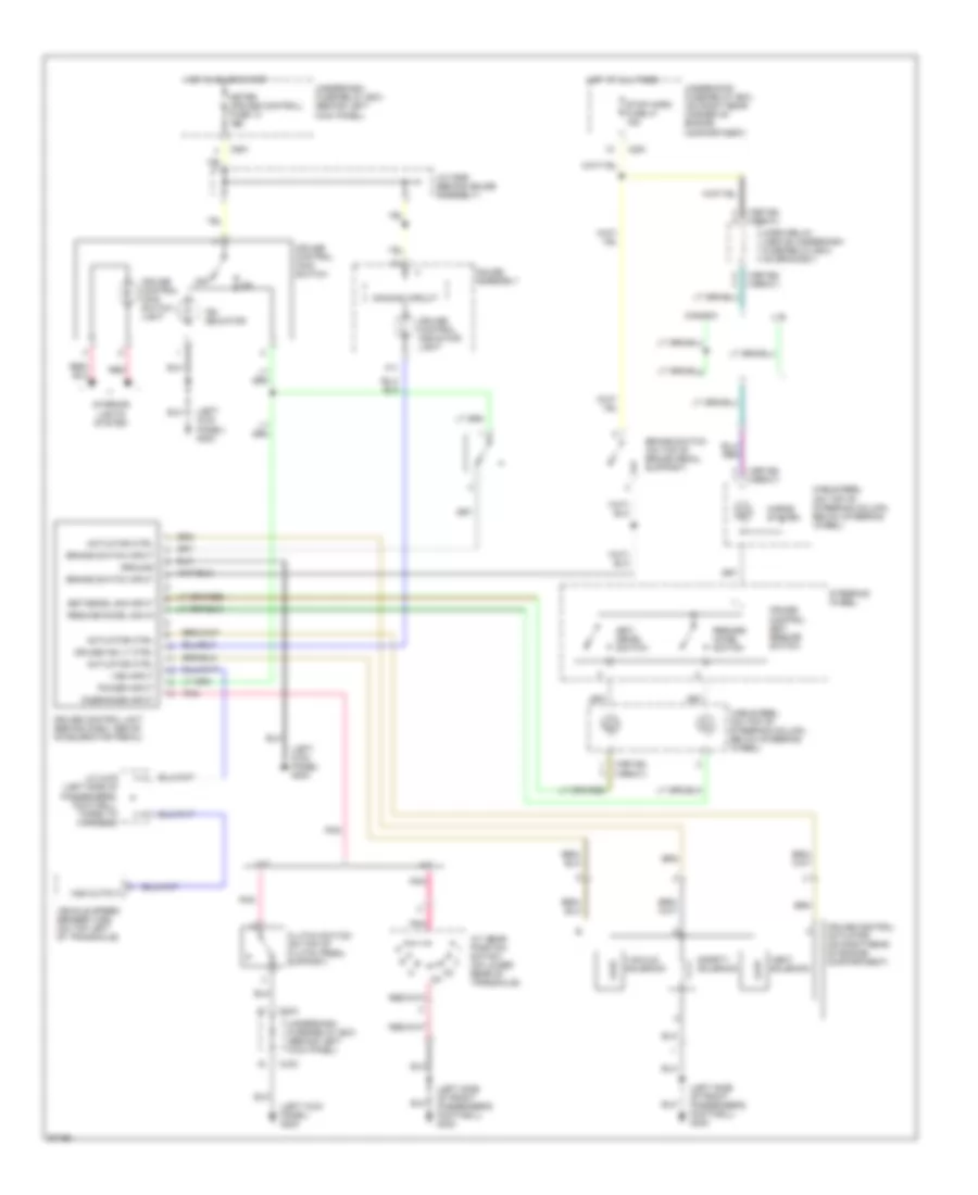
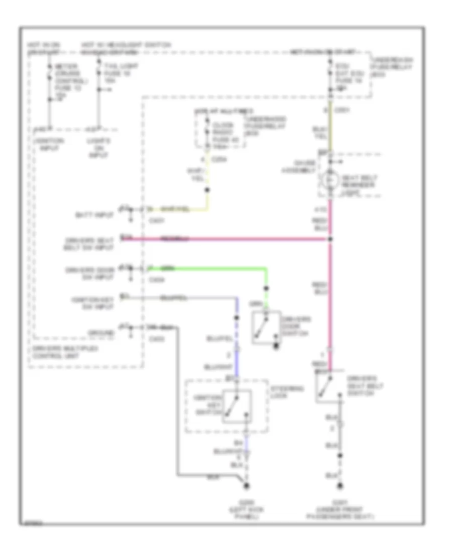
Warning System Wiring Diagrams for Honda Prelude 1997
List of elements for Warning System Wiring Diagrams for Honda Prelude 1997:
- A13
- A14 driver's door sw input
- B14 driver's seat belt sw input
- B3 ignition key sw input
- Batt input
- C254
- C431
- C433
- C434
- C551
- Clock radio fuse 43 7.5a
- Driver's door switch
- Driver's multiplex control unit
- Driver's seat belt switch
- Ecu eat ecu fuse 14 15a
- G200 (left kick panel)
- G301 (under front passenger's seat)
- Gauge assembly
- Ground
- Hot at all times
- Hot in on or start
- Hot w/ headlight switch in head or park
- Ignition input
- Ignition key switch
- Lights on input
- Meter (cruise control) fuse 13 15a
- Seat belt reminder light
- Steering lock
- Tail light fuse 10 15a
- Underdash fuse/relay box
- Underhood fuse/relay box
WIPER/WASHER
Wiper/Washer Wiring Diagram for Honda Prelude 1997
List of elements for Wiper/Washer Wiring Diagram for Honda Prelude 1997:
- (left front corner of engine compartment)
- (not used)
- (pin numbers in electrical troubleshooting manual)
- (pin numbers in service manual)
- A-d line
- A11
- A12
- A13
- B10
- C408
- C412
- C433
- C434
- C436
- C437
- C980
- D-a line
- D10
- Driver's multiplex control unit
- Fuse 13 meter (cruise control) 15a
- G100
- G100 (left front corner of engine compartment)
- G200 (left kick panel)
- Ground
- Hot in on or start
- Ignition input
- Int
- Int dwell timer input
- Intermittent dwell time controller
- Intermittent on input
- Intermittent wiper ctrl
- Mist
- Mist switch
- Off
- Park
- Park input
- Passenger's multiplex control unit (behind right kick panel)
- Pnk
- Run
- Underdash fuse/relay box (behind left kick panel)
- Wash
- Wash on input
- Washer switch
- Windshield washer motor (in washer fluid reservoir)
- Windshield wiper intermittent relay (on rear of left strut tower)
- Windshield wiper motor (behind left side of air scoop)
- Windshield wiper/washer switch
- Wiper fuse 17 30a
- Wiper switch

 Čeština
 Dansk
Dansk Deutsch
 Ελληνικά
 English
 English
 Suomi
Suomi Français
 Français
 עברית
עברית Hrvatski
 Magyar
 Italiano
 日本語
日本語 한국어
한국어 Nederlands
 Polski
 Português
 Português
 Română
 Русский
 Slovenčina
 Slovenščina
 Svenska
 Türkçe
 中文 (中国)