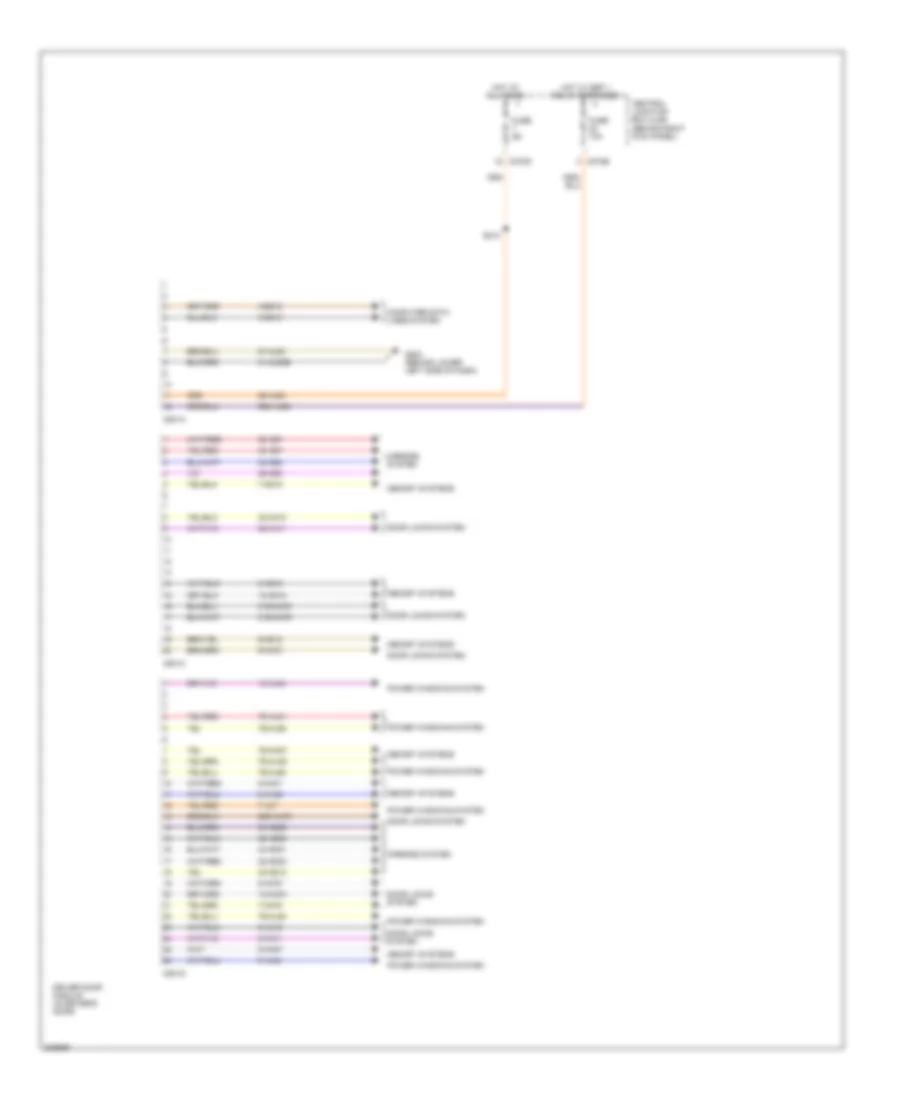
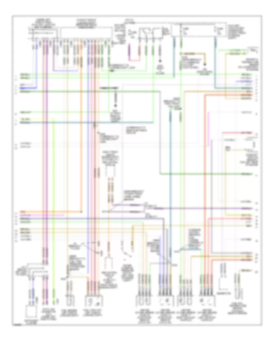
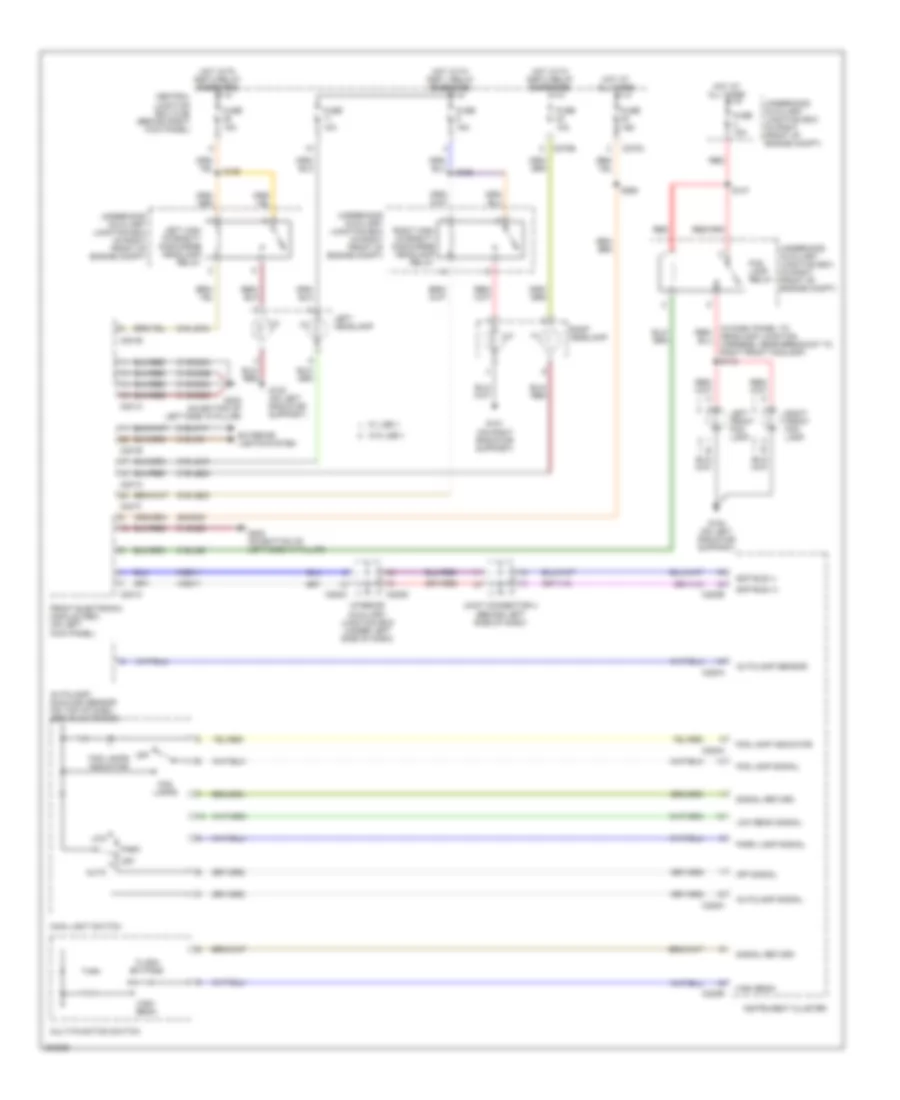
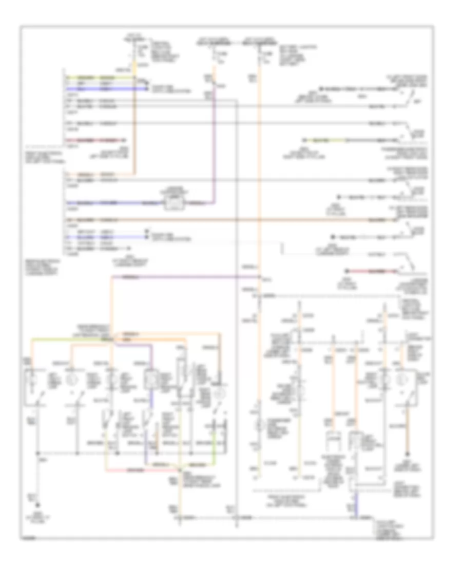
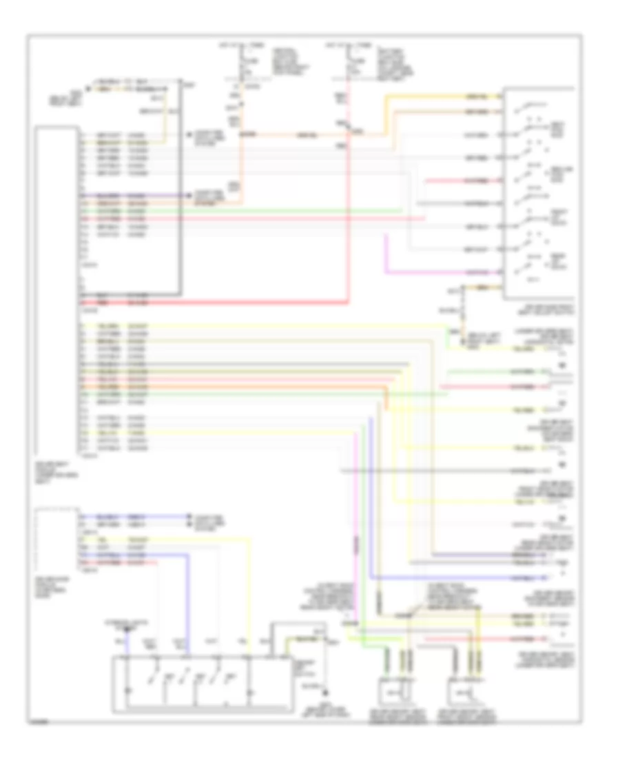
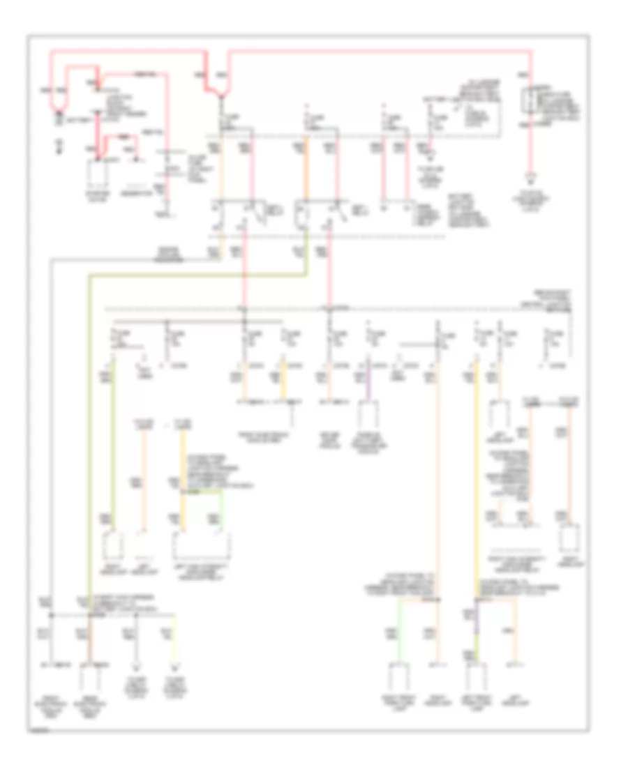
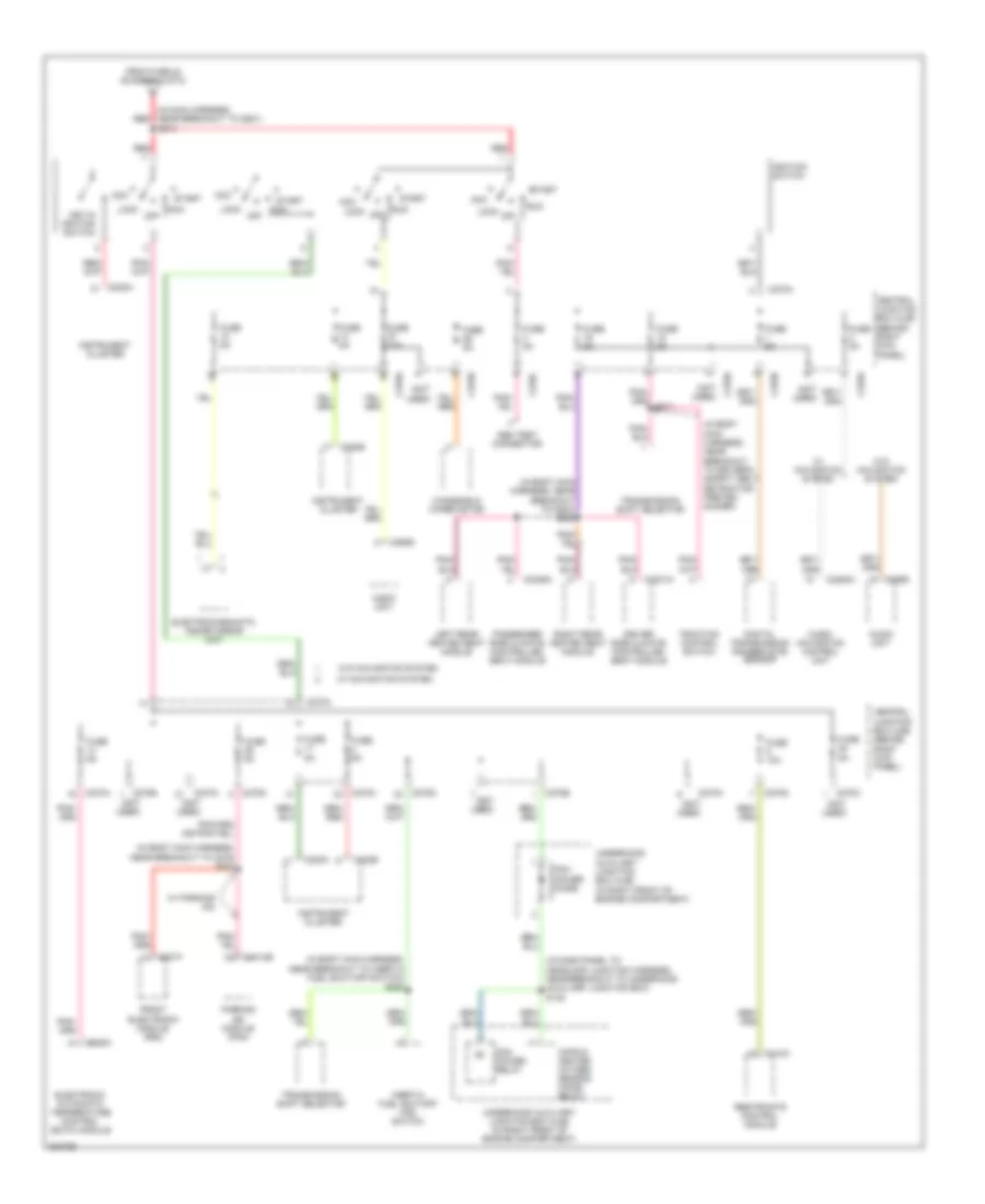
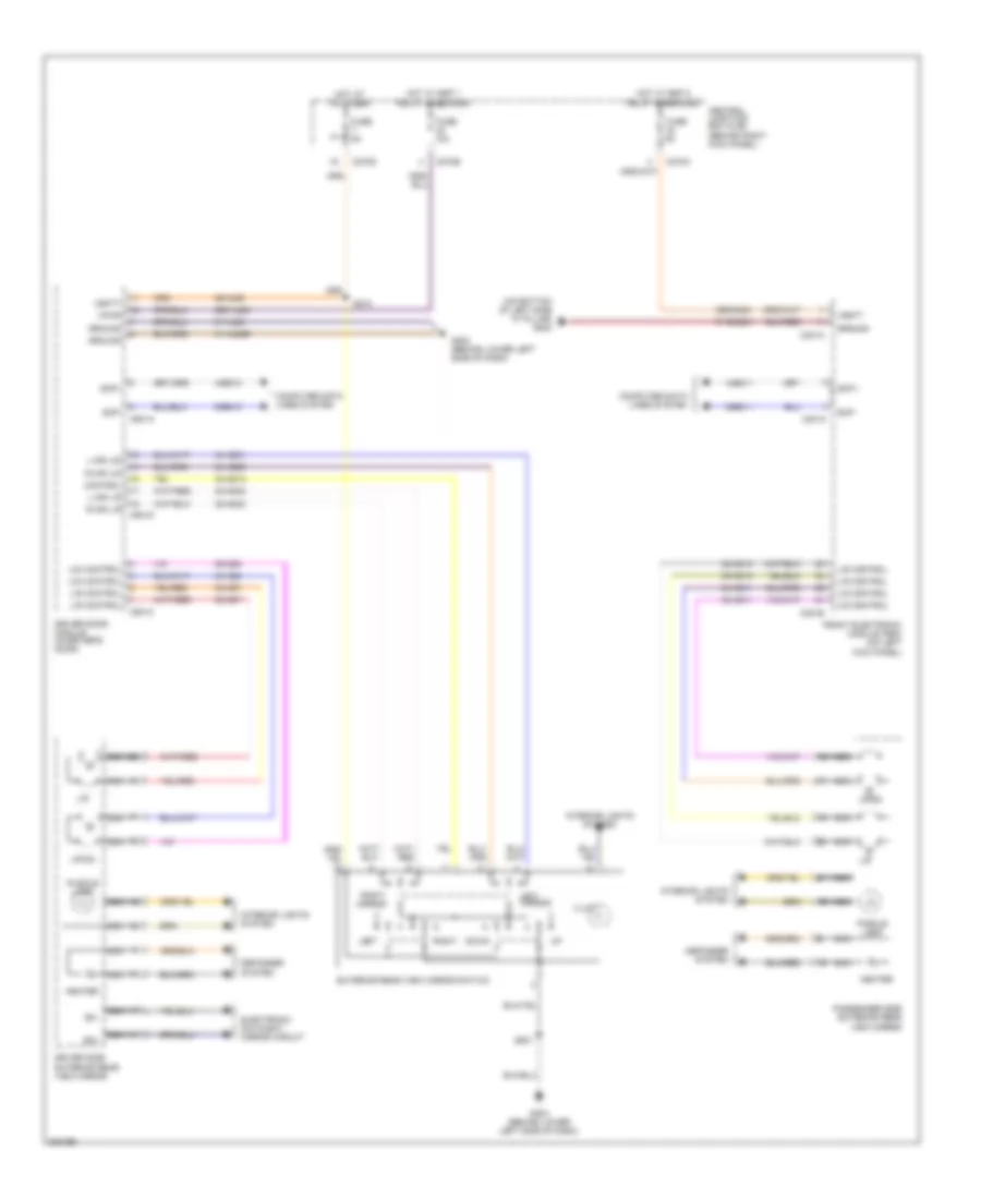
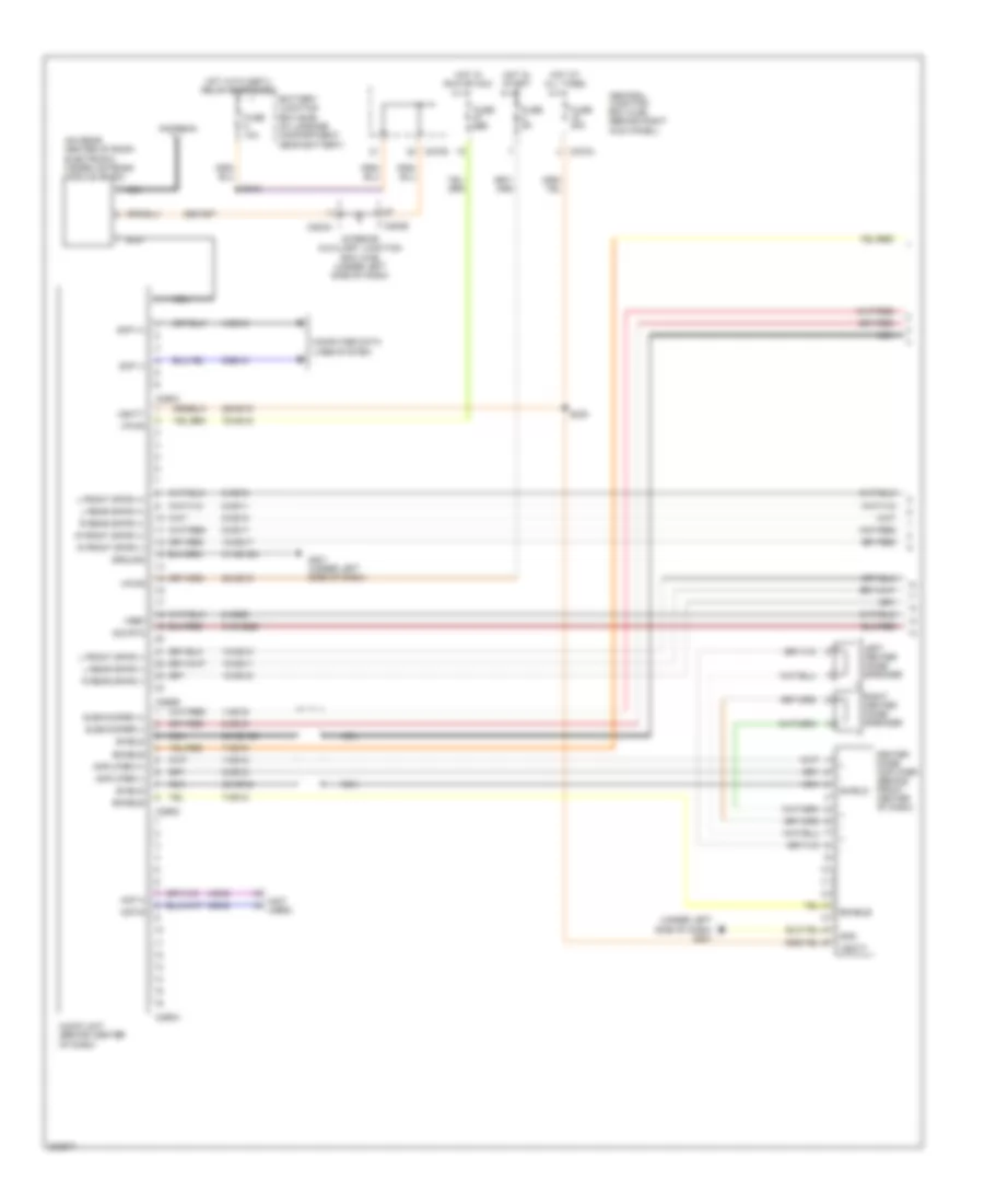
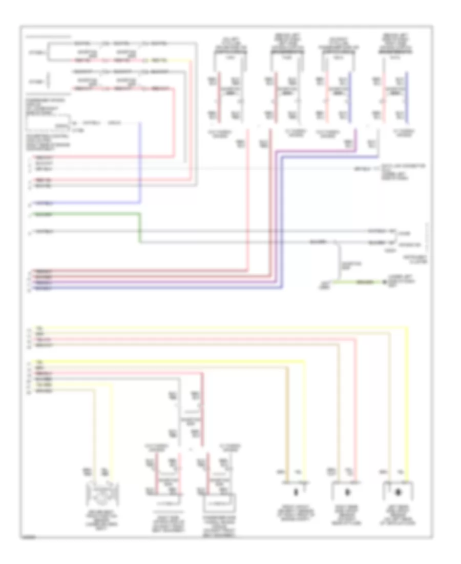
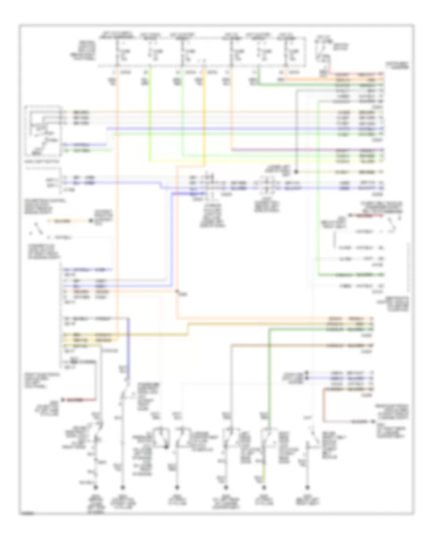
AIR CONDITIONING
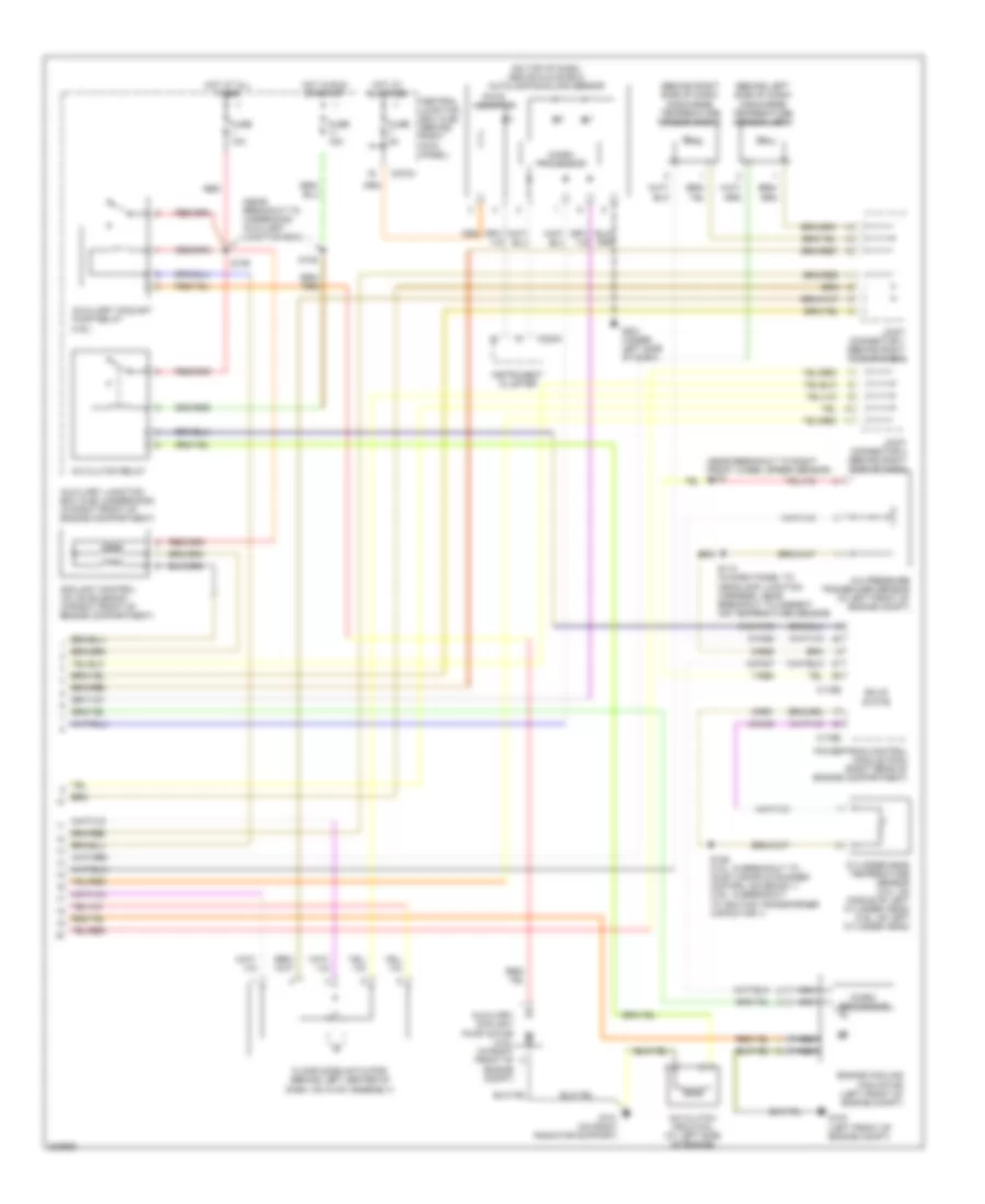
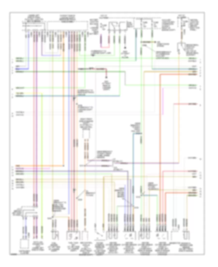
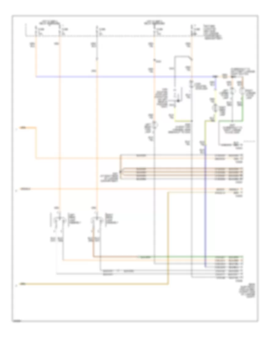
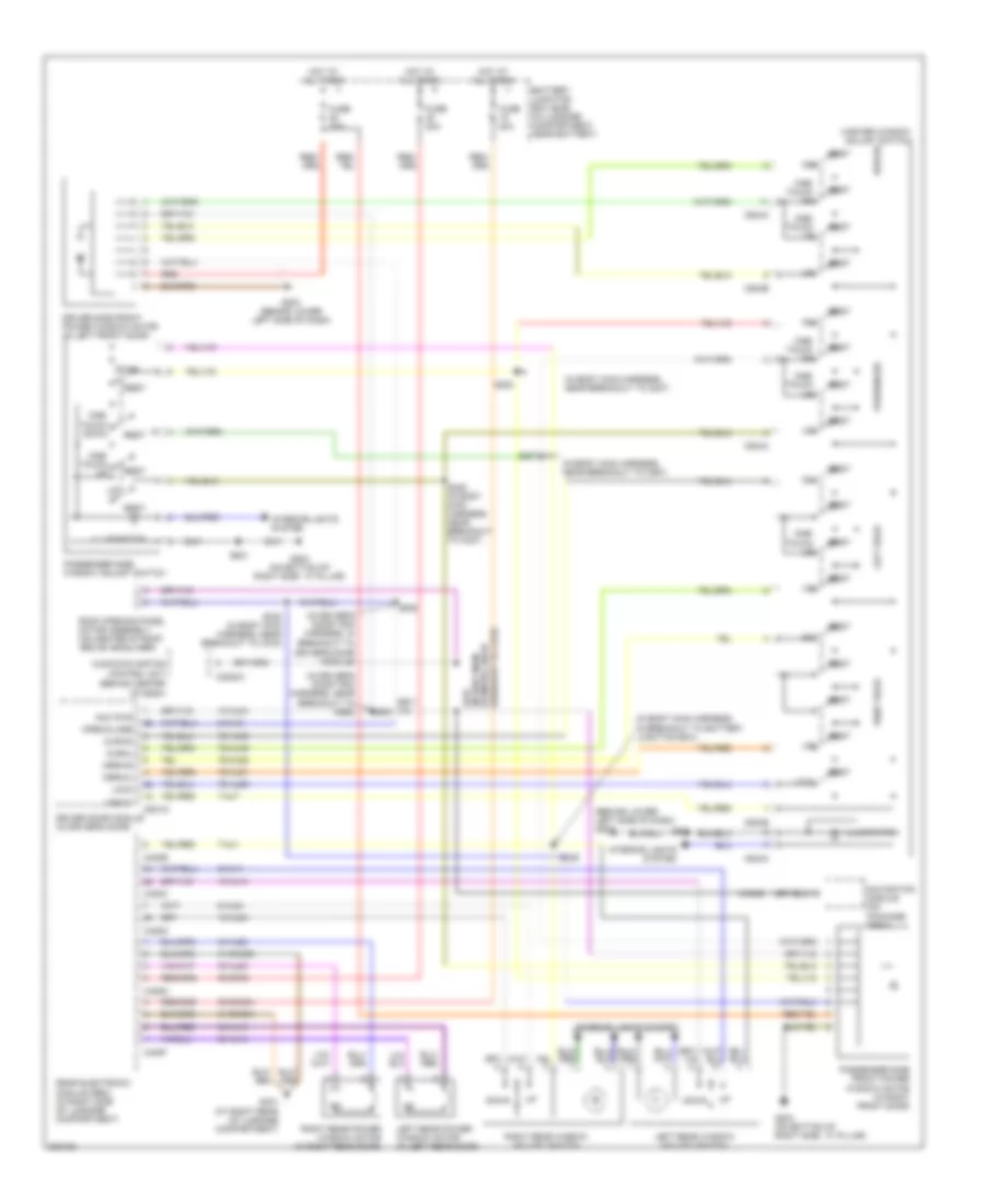
Automatic A/C Wiring Diagram (1 of 2) for Lincoln LS 2005
 https://portal-diagnostov.com/license.html
Automotive Electricians Portal FZCO
Automotive Electricians Portal FZCO
https://portal-diagnostov.com/license.html
https://portal-diagnostov.com/license.html
Automotive Electricians Portal FZCO
Automotive Electricians Portal FZCO
List of elements for Automatic A/C Wiring Diagram (1 of 2) for Lincoln LS 2005:
- (at right front of engine compt) ambient air temperature sensor
- (behind center of dash) evaporator discharge air temperature sensor
- (behind right side of dash) joint connector 1
- (in air conditioning harness, near breakout to heater blower motor) s214
- (in dash panel to headlamp junction harness, near breakout to right front foglamp) s104
- (on bottom of right side "a" pillar) g204
- 10-fa53
- 20-fa10
- 29-fa10
- 30s-fa45
- 31-fa10
- 31-fa45
- 31s-fa18
- 31s-fa23
- 32-fb5
- 32-fb6
- 32-fb7
- 32-fb8
- 33-fb5
- 33-fb6
- 33-fb7
- 33-fb8
- 4-fa1
- 4-fa10
- 5-fa10
- 60a
- 7-fa1
- 8-fa44
- 8-fa45
- 8-fa47
- 8-fa48
- 8-fa49
- 8-fa51
- 8-fa53
- 8-fb5
- 8-fb6
- 8-fb7
- 8-fb8
- 9-fa2
- 9-fa3
- 9-fa44
- 9-fa48
- 9-fa49
- 9-fb8
- 91s-fa76
- 91s-fb3
- 91s-fb4
- 91s-hb7
- Auxiliary junction box (ajb) (underhood) (in right front of engine compartment)
- Blower motor relay
- C228a
- C228b
- C270a
- Central junction box (cjb) (behind right kick panel)
- Data link connector (dlc) (under left side of dash)
- Defogger system
- Defrost mode actuator (behind right side of dash, on hvac assembly)
- Electronic automatic temperature control (eatc) module (behind center of dash)
- Fresh/recirculation door actuator (behind right side of dash, on hvac assembly)
- Fuse 10a
- Fuse 15a
- Fuse 30a
- Fuse 5a
- G201 (under left side of dash)
- Heater blower control module (behind right center of dash)
- Heater blower motor (behind right center of dash)
- Hot at all times
- Hot in run
- Hot in run or start
- In-line fuse (at right kick panel)
- In-vehicle temperature sensor (behind center of dash)
- Joint connector 4 (behind left
- Panel mode actuator (behind right side of dash, on hvac assembly)
- Side of dash)
- Solid state
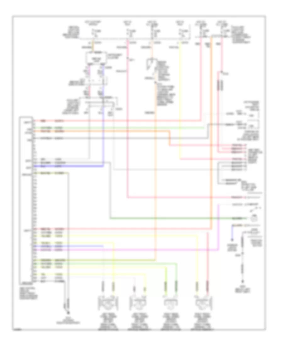
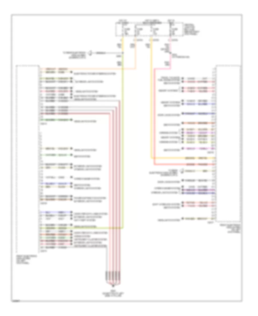
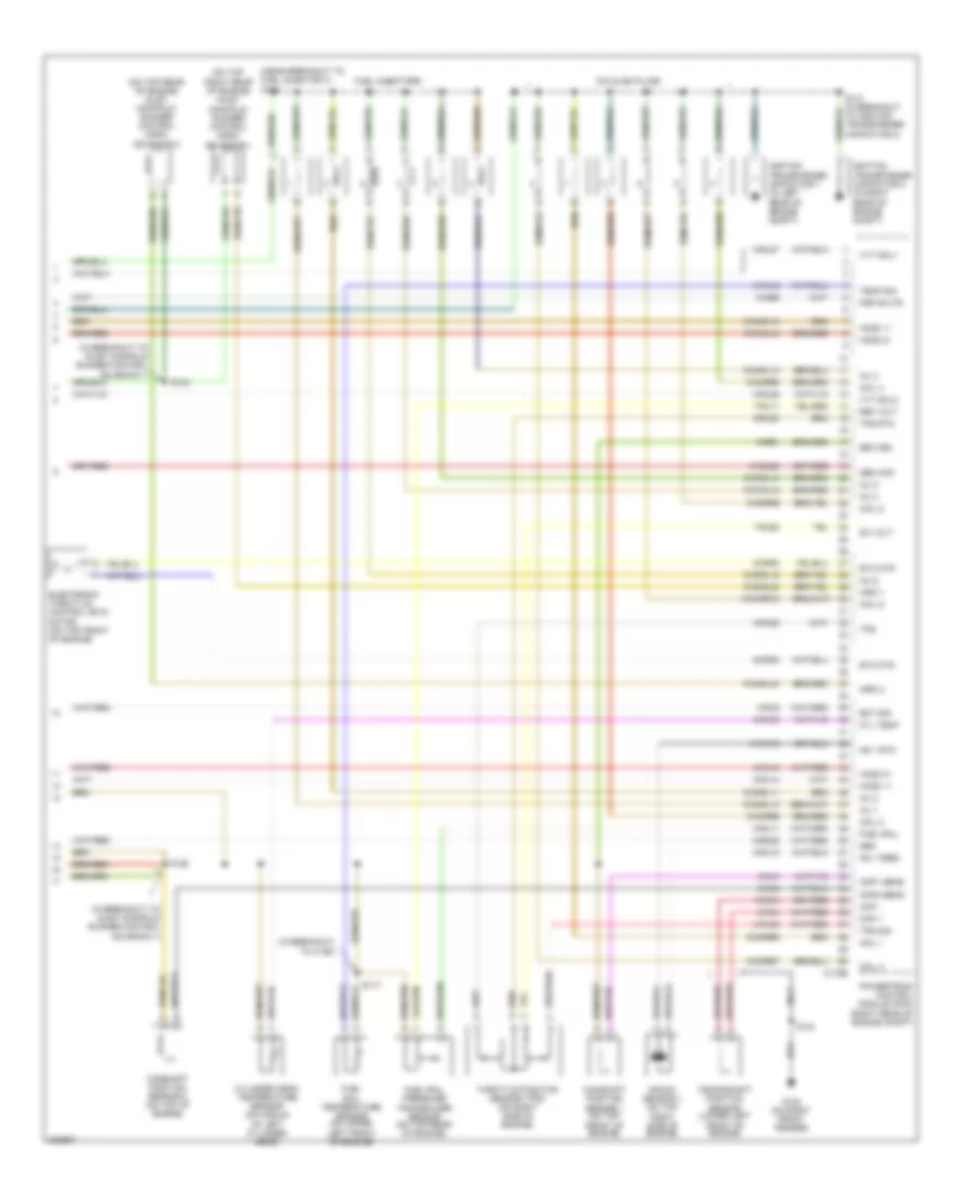
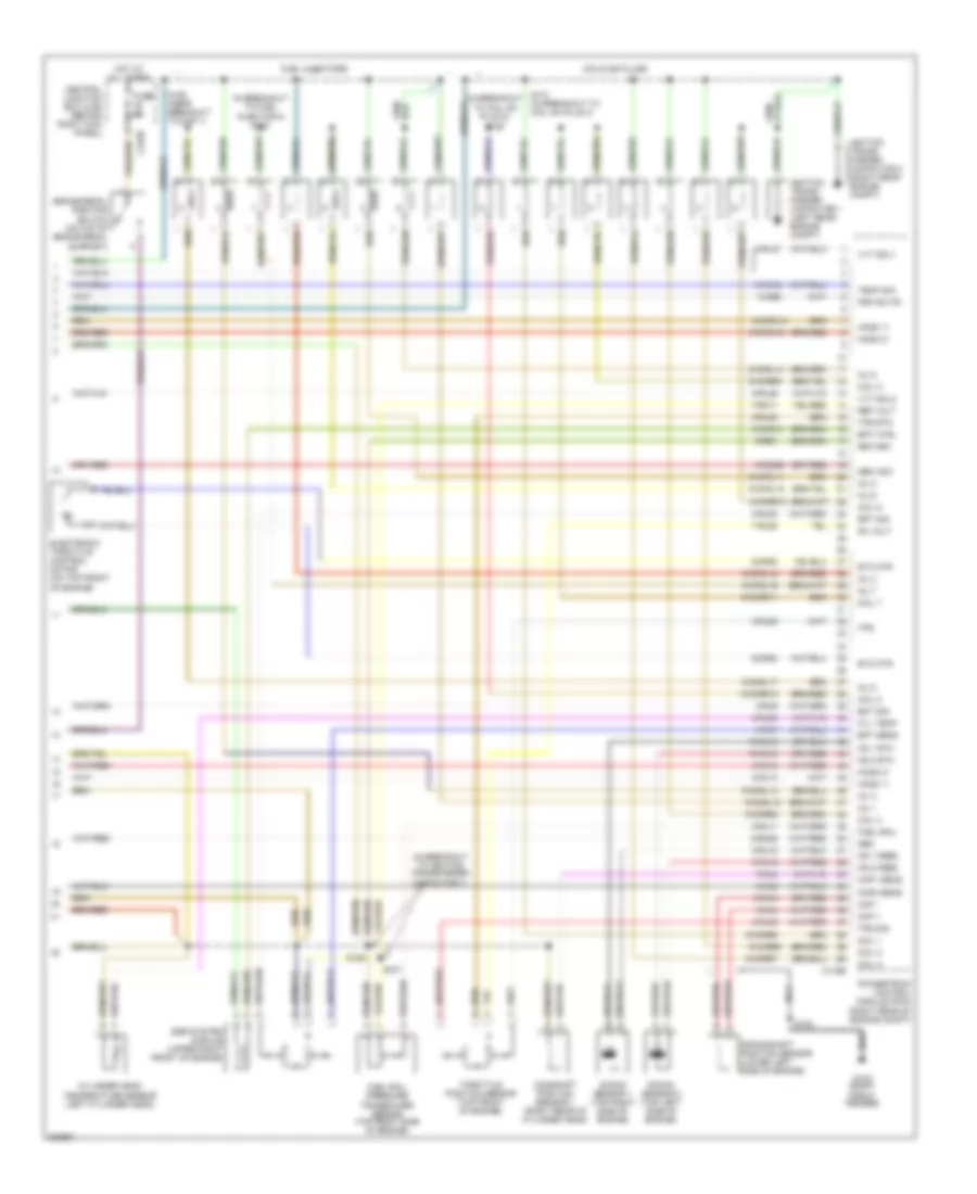
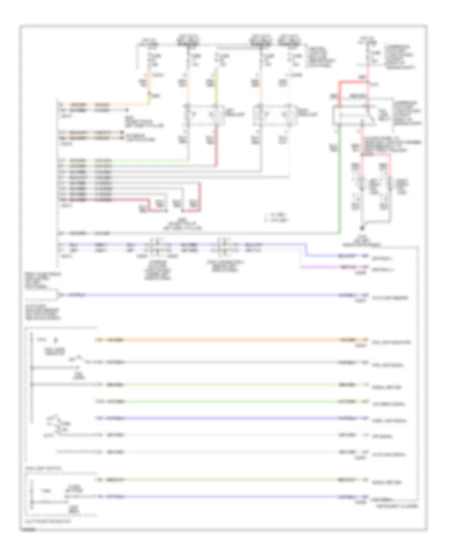
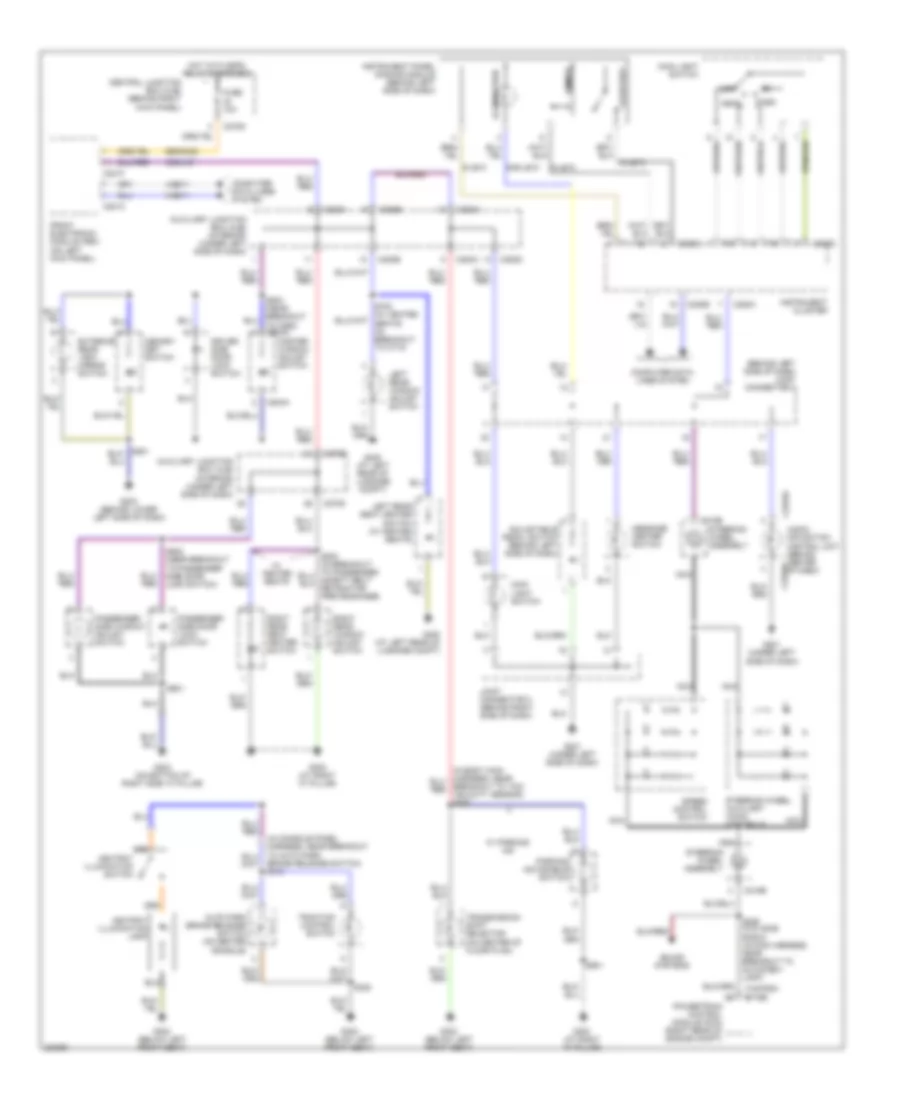
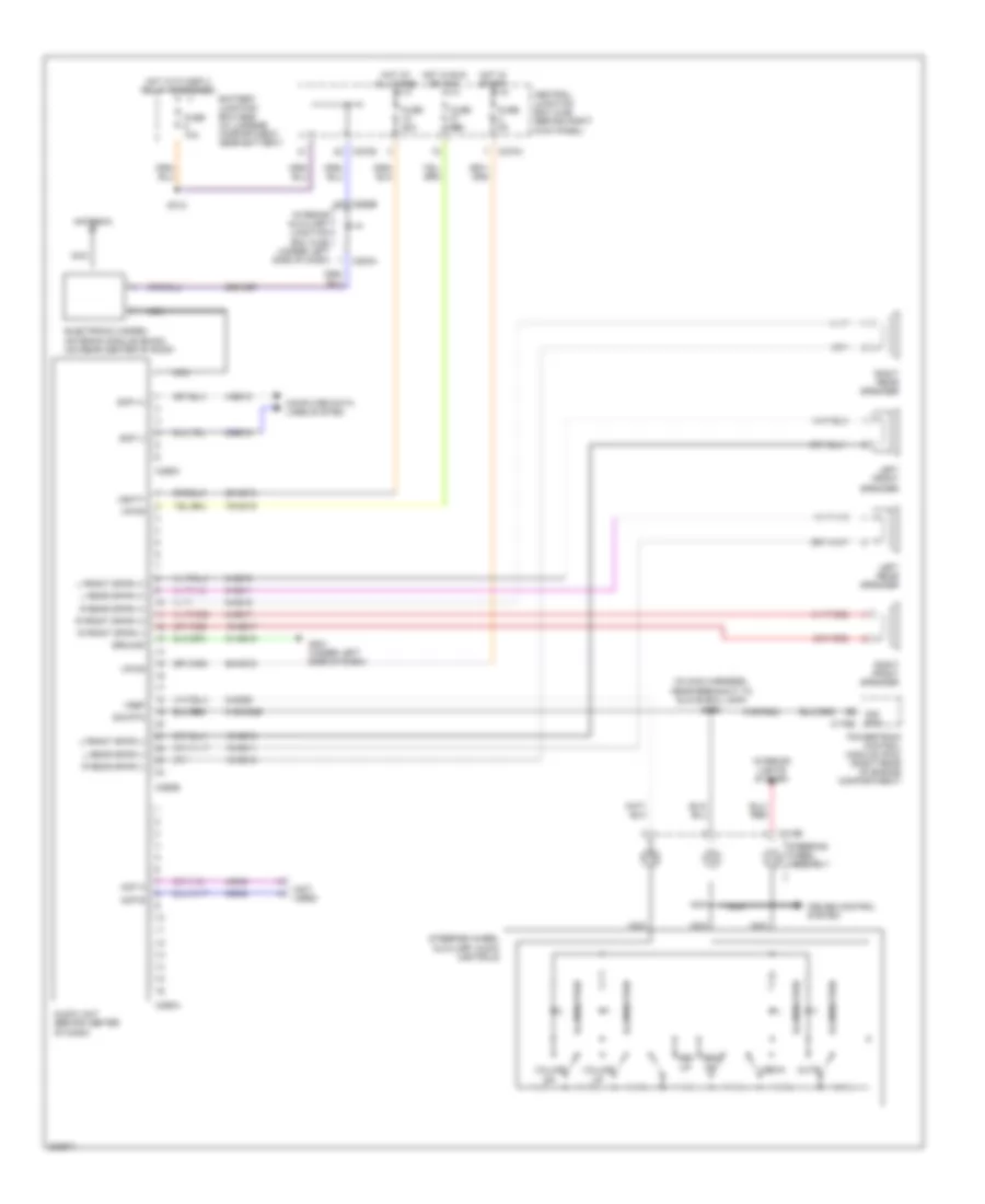
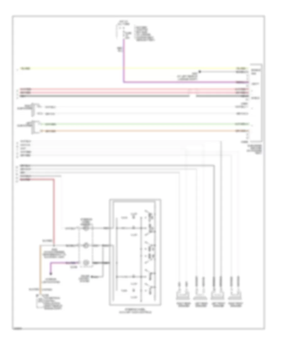
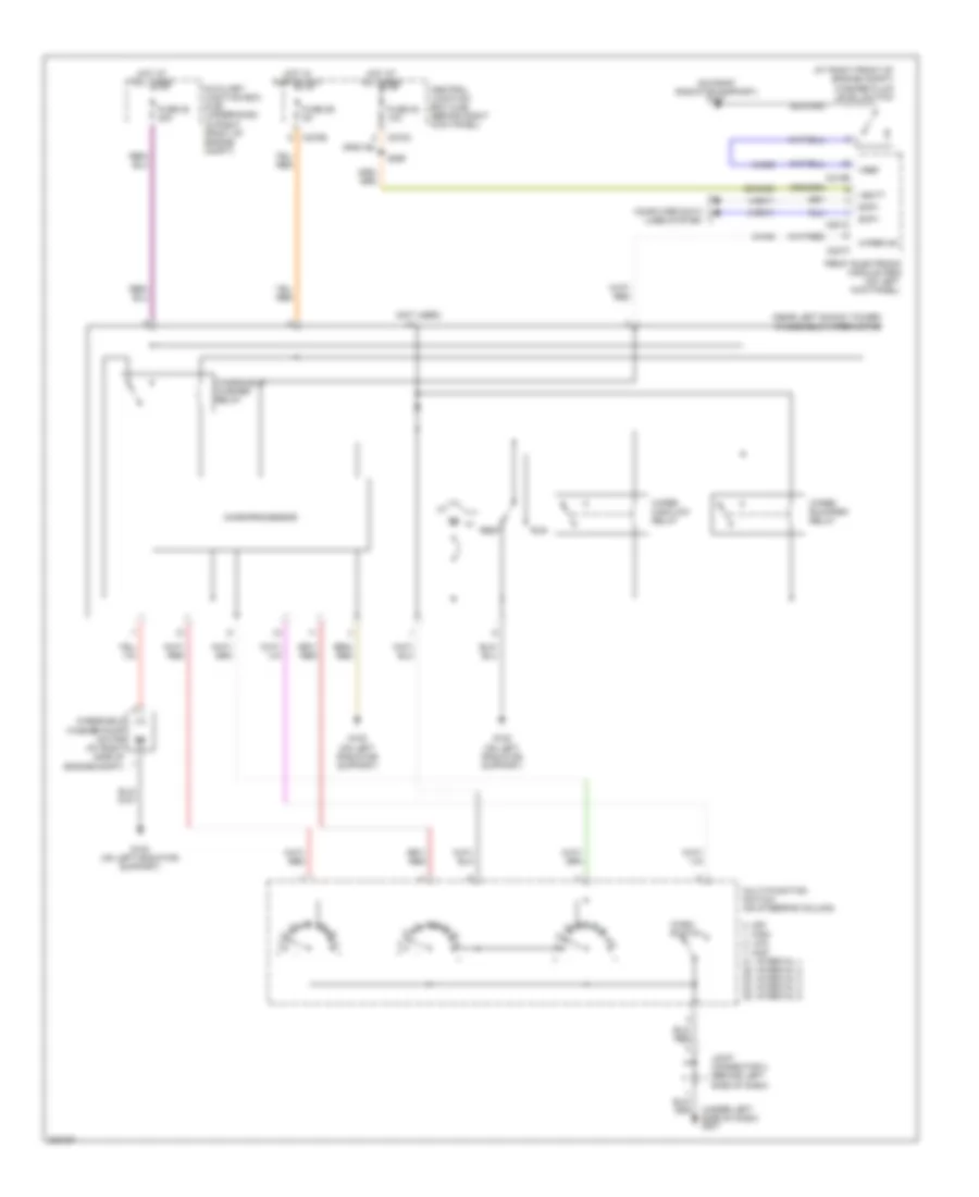
Automatic A/C Wiring Diagram (2 of 2) for Lincoln LS 2005
List of elements for Automatic A/C Wiring Diagram (2 of 2) for Lincoln LS 2005:
- (behind left side of dash) discharge temperature sensor (left)
- (behind right side of dash) discharge temperature sensor (right)
- (near breakout to underhood auxiliary junction box)
- (on top of dash, above glove box) autolamp/sunload sensor
- 7-re8
- 8-fa88
- 8-pa47
- 8-rj33
- 9-re1
- 9-re8
- 91s-fa79
- A/c clutch field coil (at left side of engine)
- A/c clutch relay
- A/c pressure transducer sensor (in left front of engine compt)
- Auxiliary coolant pump motor (3.9l) (in right front of engine compt)
- Auxiliary coolant pump relay (3.9l)
- Auxiliary junction box (ajb) (underhood) (in right front of engine compartment)
- C175b
- C175e
- C220a
- C270a
- Central junction box (cjb) (behind right kick panel)
- Coolant control valve solenoid (in right front of engine compartment)
- Cylinder-head temperature sensor (3.0l: on middle of left cylinder head) (3.9l: on left cylinder head)
- Engine cooling fan motor (left front of engine compt)
- Floor mode actuator (behind left center of dash, on hvac assembly)
- Fuse 10a
- Fuse 15a
- Fuse 5a
- G101 (on right radiator support)
- G103 (left front of engine compt)
- G201 (under left side of dash)
- Hot at all times
- Hot in run or start
- Instrument cluster
- Joint connector 1 (behind right side of dash)
- Joint connector 2 (behind right side of dash)
- Micro- processor
- Nca
- Pats indicator
- Powertrain control module (pcm) (right rear of engine compartment)
- Red
- S113 (in dash panel to headlamp junction harness, near breakout to ambient air temperature sensor)
- S126 (3.0l: in breakout to inlet manifold runner control solenoid 1) (3.9l: in breakout
- S135
- S136
- Solid state
- To ignition transformer capacitor 1)
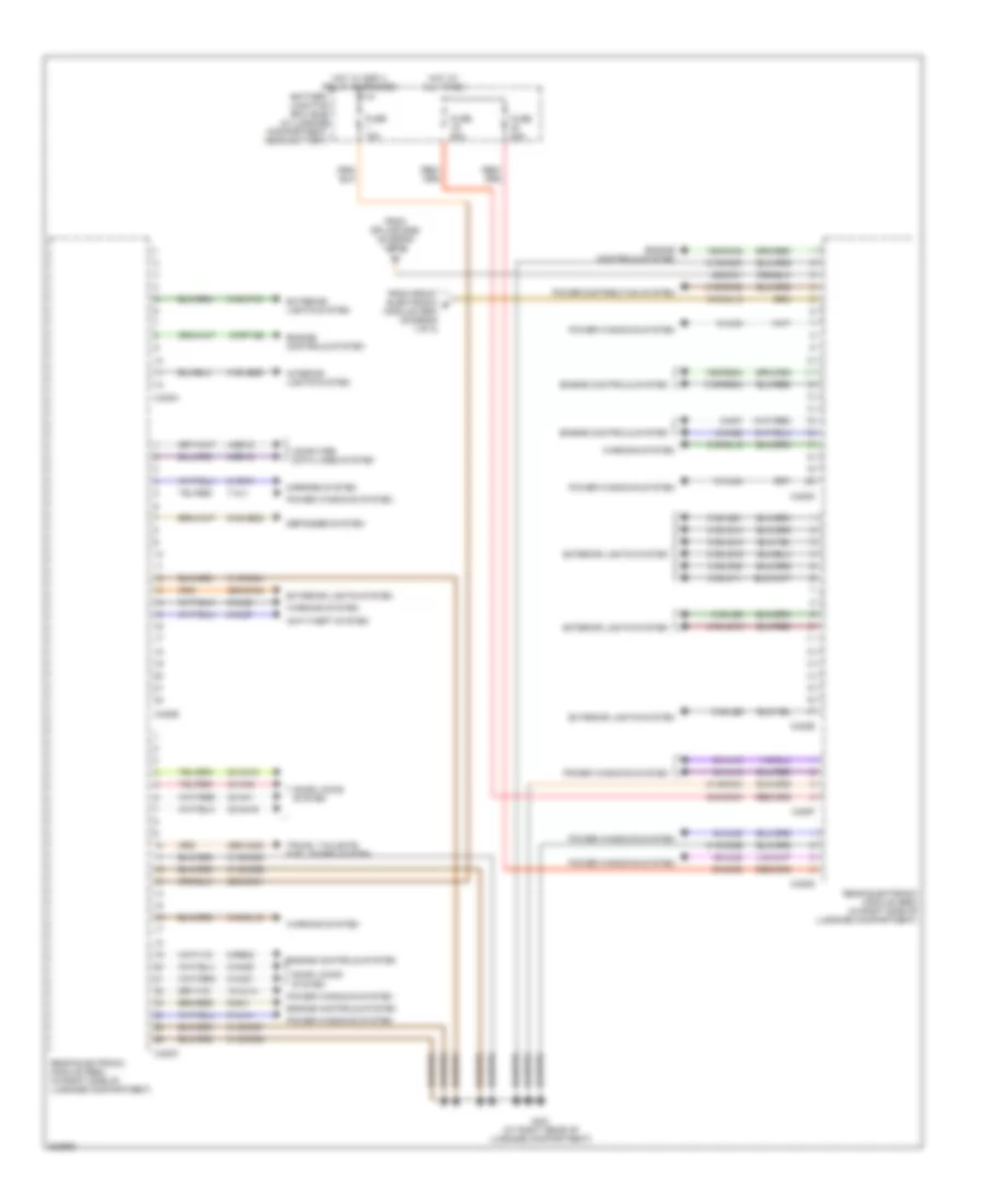
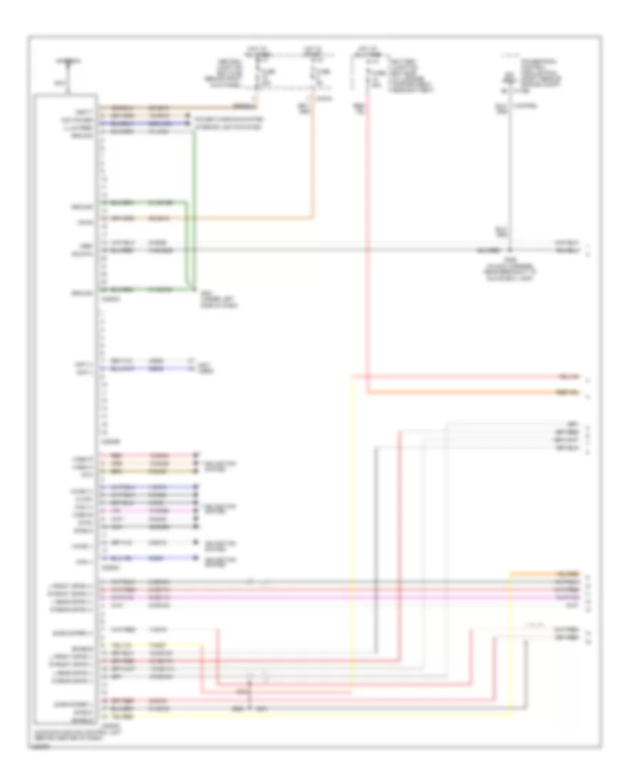
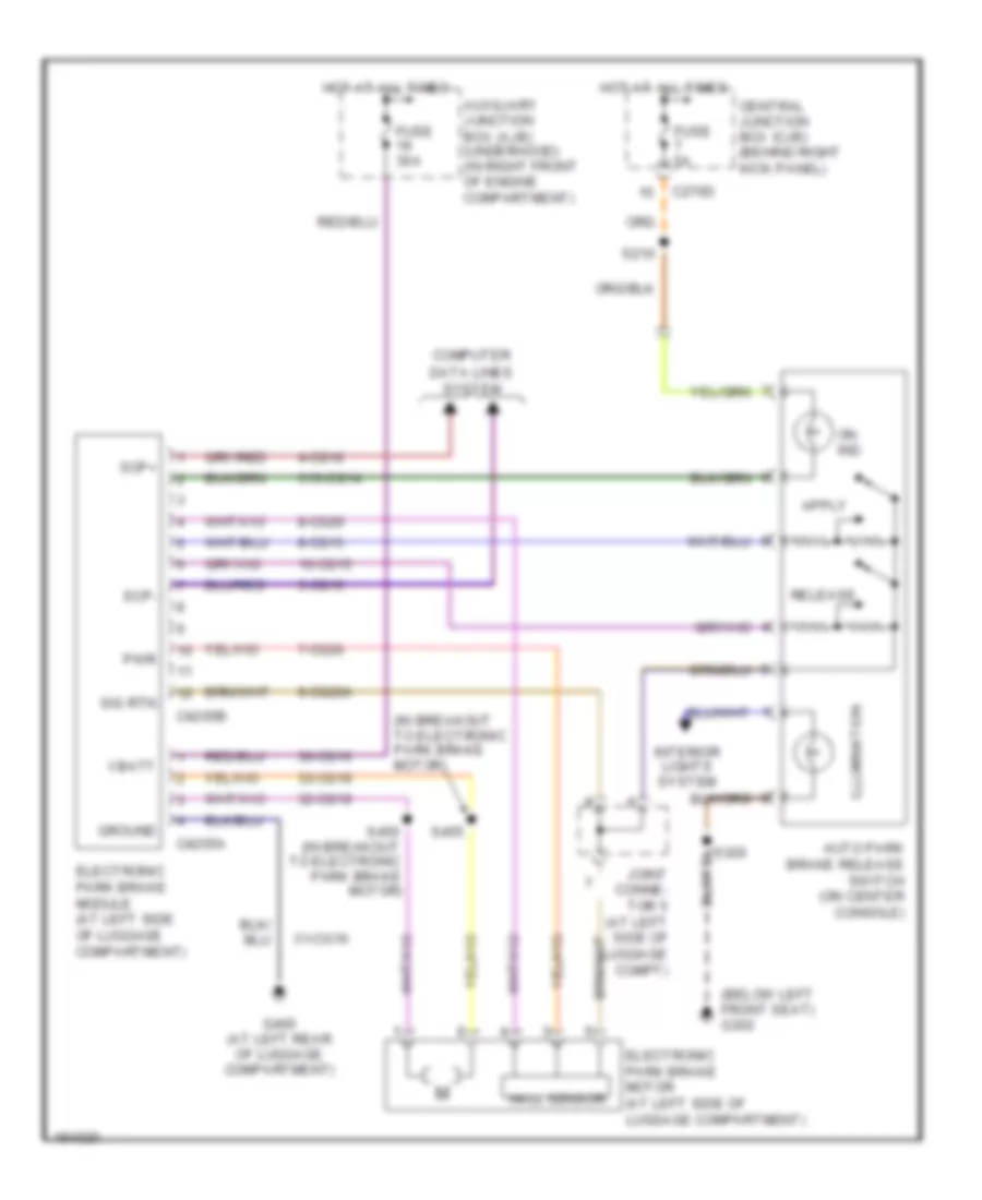
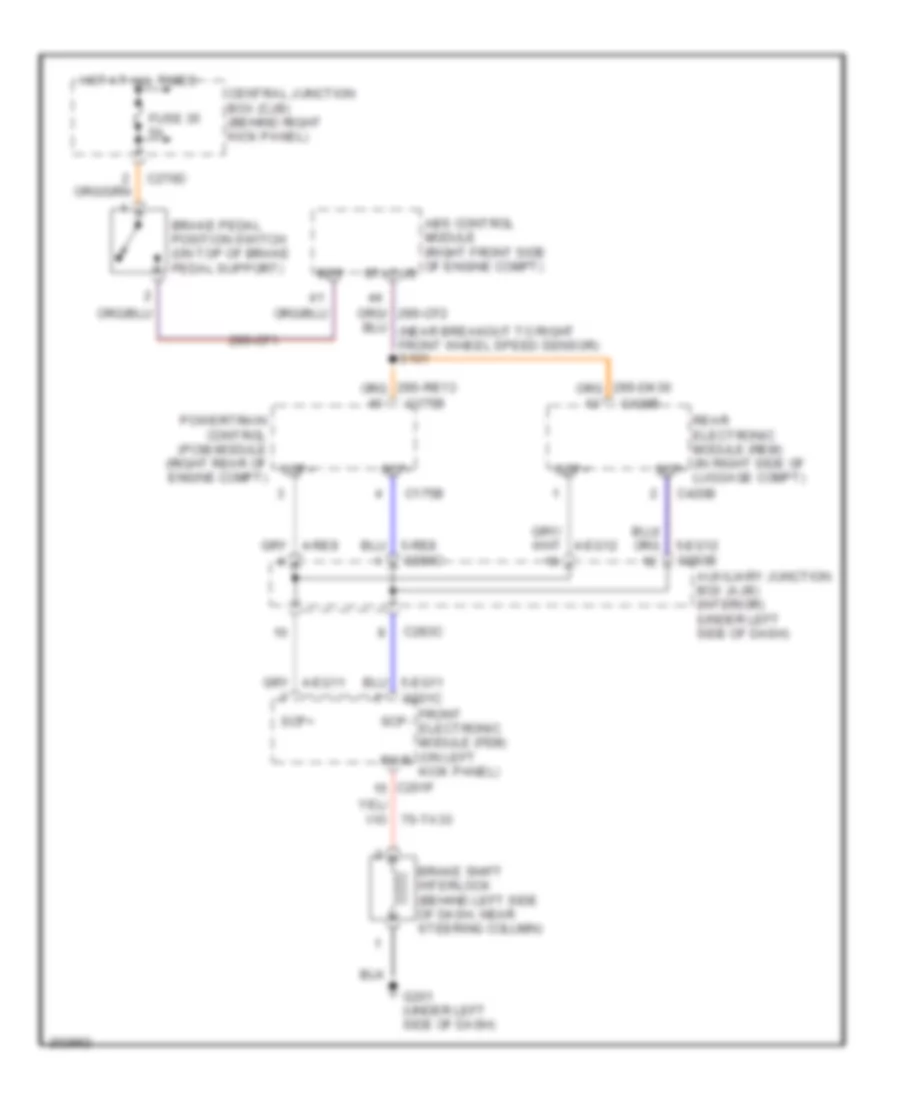
ANTI-LOCK BRAKES
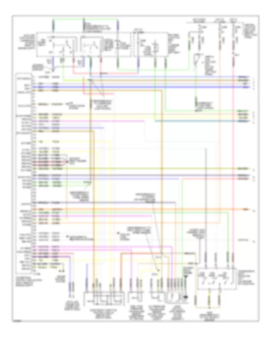
Anti-lock Brakes Wiring Diagram, with Stability Assist for Lincoln LS 2005
List of elements for Anti-lock Brakes Wiring Diagram, with Stability Assist for Lincoln LS 2005:
- (in dash panel to headlamp junction harness, near breakout to right front wheel speed sensor) s101
- (in dash pnl to headlamp junction harness, near breakout to left front wheel speed sensor)
- 10-cc17
- 10-cf51
- 20-cf6a
- 29s-cf1
- 29s-cf2
- 29s-dk30
- 29s-re13
- 30-cf13
- 30-cf6a
- 31-cf6a
- 31-cf6b
- 31s-cf45
- 4-cf6
- 4-cf66
- 5-cf6
- 5-cf66
- 7-cc1
- 7-cf32
- 7-cf34
- 7-cf38
- 7-cf40
- 7-cf64
- 7-cf65
- 8-cc18
- 8-cf32
- 8-cf34
- 8-cf38
- 8-cf40
- 8-cf51
- 8-cf54
- 8-cf63
- 8-cf64
- 8-cf65
- 8-cf68
- 8-gn14
- 9-cc1
- 9-cf51
- 9-cf64
- 9-cf65
- 9-cf68
- Abs control module (right front side of engine compartment)
- Abs ind lamp
- Abs test connector (in left
- Auxiliary junction box (ajb) (interior) (under left side of dash)
- Auxiliary junction box (ajb) (underhood) (in right front of engine compartment)
- Bpfs nc
- Bpfs no
- Bpfs sta
- Brake booster sensor (in left rear of engine compt)
- Brake pedal position sensor (at left shock tower)
- Brake pedal position switch (on top of brake pedal support)
- C175a
- C220b
- C270a
- C270c
- C270d
- C283c
- C283d
- C4014b
- C420b
- Can2+
- Can2-
- Central junction box (cjb) (behind right kick panel)
- Fuse 30a
- Fuse 40a
- Fuse 5a
- G101 (on right radiator support)
- G202 (on bottom of left side ``a" pillar)
- G302 (below left front seat)
- Gnd
- Ground
- Hot at all times
- Hot in run
- Hot in start or run
- Illum
- Ind
- Instrument cluster
- Interior lights system
- J/c 4 (behind left side of dash)
- Left front wheel speed sensor (on left front wheel assembly, on spindle assembly)
- Left rear wheel speed sensor (on left rear wheel assembly, on brake knuckle)
- Navigation module (on package tray)
- On/off
- Parking aid module (pam) (on left rear of package tray)
- Powertrain control module (pcm) (right rear of engine compt)
- Primary brake pressure sensor (in left rear of engine compt)
- Pwr
- Rear electronic module (rem) (in right side of luggage compt)
- Rear of engine compt)
- Red
- Right front wheel speed sensor (on right front wheel assembly, on spindle assembly)
- Right rear wheel speed sensor (on right rear wheel assembly, on brake knuckle)
- S122
- S140
- S146
- S211
- S320
- Scp+
- Scp-
- Sig rtn
- Steering position sensor (on steering column)
- Traction control switch
- Vbatt
- Vpwr
- Vref
- Vss
- Yaw velocity sensor (on center of floor pan)
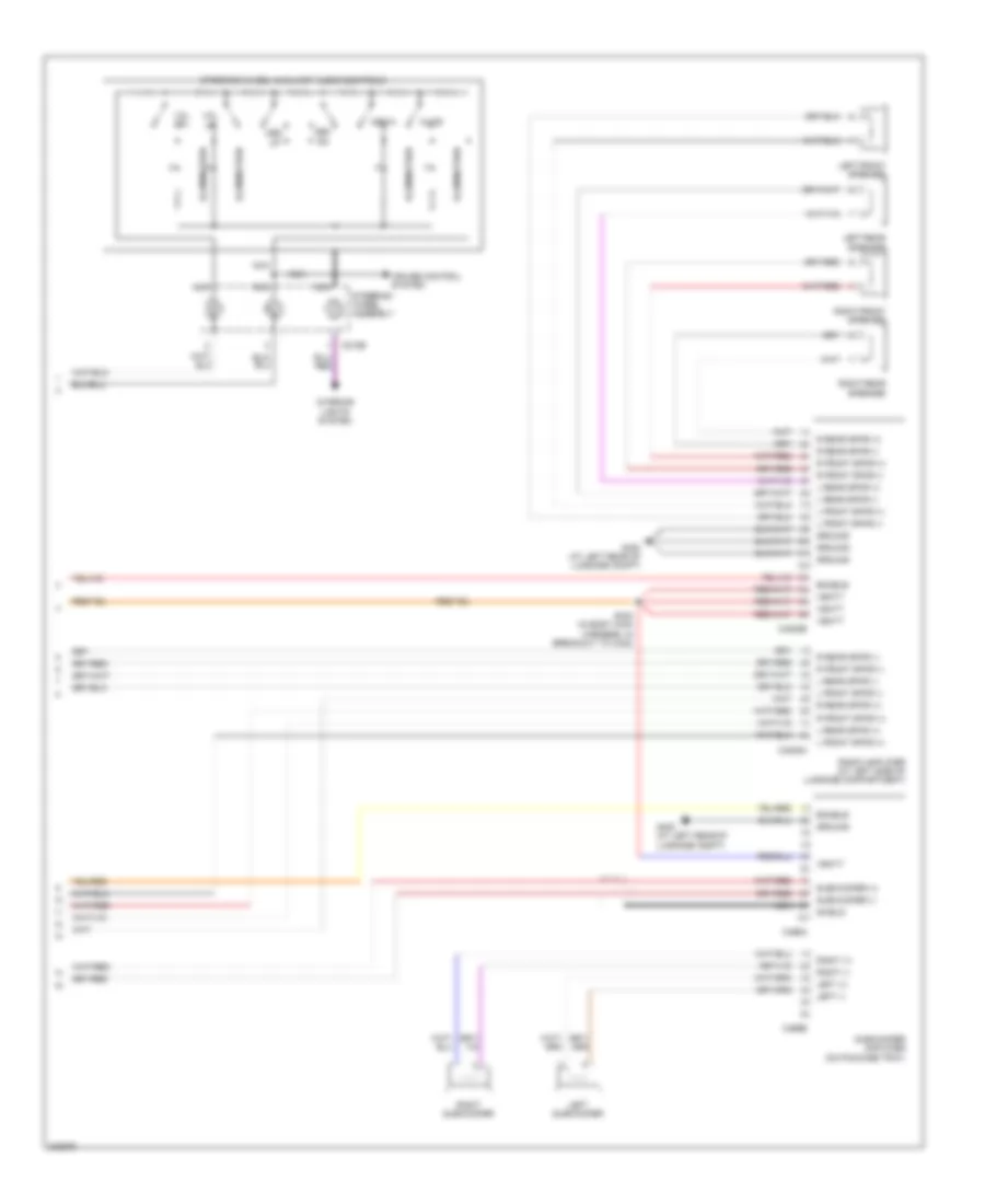
Anti-lock Brakes Wiring Diagram, without Stability Assist for Lincoln LS 2005
List of elements for Anti-lock Brakes Wiring Diagram, without Stability Assist for Lincoln LS 2005:
- (on package tray) navigation module
- 20-cf6a
- 29s-cf58
- 30-cf13
- 30-cf6a
- 31-cf6a
- 31-cf6b
- 31s-cf45
- 4-cf6
- 5-cf6
- 7-cf32
- 7-cf34
- 7-cf38
- 7-cf40
- 8-cf32
- 8-cf34
- 8-cf38
- 8-cf40
- 8-cf54
- 8-cf63
- 8-gn14
- Abs control module (right front side of engine compartment)
- Abs ind lamp
- Abs test connector (in left
- Auxiliary junction box (ajb) (interior) (under left side of dash)
- Auxiliary junction box (ajb) (underhood) (in right front of engine compartment)
- Brake pedal position switch (on top of brake pedal support)
- C220b
- C270a
- C270c
- C270d
- C283c
- C283d
- C4014b
- Central junction box (cjb) (behind right kick panel)
- Fuse 30a
- Fuse 40a
- Fuse 5a
- G101 (on right radiator support)
- G202 (on bottom of left side ``a" pillar)
- G302 (below left front seat)
- Ground
- Hot at all times
- Hot in run
- Hot in start or run
- Illum
- Ind
- Instrument cluster
- Interior lights system
- J/c 4 (behind left side of dash)
- Left front wheel speed sensor (on left front wheel assembly, on spindle assembly)
- Left rear wheel speed sensor (on left rear wheel assembly, on brake knuckle)
- On/off
- Parking aid module (pam) (on left rear of package tray)
- Rear of engine compt)
- Red
- Right front wheel speed sensor (on right front wheel assembly, on spindle assembly)
- Right rear wheel speed sensor (on right rear wheel assembly, on brake knuckle)
- S101 (in dash panel to headlamp junction harness, near breakout to right front wheel speed sensor)
- S122
- S211
- S320
- Scp+
- Scp-
- Traction control switch
- Vbatt
- Vpwr
- Vss
ANTI-THEFT
Forced Entry Wiring Diagram for Lincoln LS 2005
List of elements for Forced Entry Wiring Diagram for Lincoln LS 2005:
- 20-dk20
- 29-aj80
- 29s-aj86
- 29s-dk31
- 31s-aa78
- 31s-aa79
- 31s-gl12
- 31s-gl19
- 31s-gl46
- 31s-gl47
- 4-eg11
- 4-eg12
- 4-eg13
- 5-eg11
- 5-eg12
- 5-eg13
- 8-gl20
- 8-gl27
- 8-gl7
- 91-aj80
- 91s-gj7
- 91s-gl13
- Anti-theft hood switch (in top left front of engine compartment)
- Anti-theft luggage compartment switch (on right side of deck lid)
- Auxiliary junction box (ajb) (underhood) (in right front of engine compt)
- Battery junction box (bjb) (in luggage compt, near battery)
- C201c
- C201e
- C201f
- C270d
- C270e
- C420b
- C420c
- C420d
- C501a
- C501c
- Central junction box (behind right kick panel)
- Computer data lines system
- Door ajar
- Driver door module (in driver's door)
- Driver side front door lock unit (in left front door)
- Front electronic module (fem) (on left kick panel)
- Fuse 10a
- Fuse 15a
- Fuse 20a
- Fuse 5a
- G100 (on left radiator support)
- G203 (behind lower left side of dash)
- G204 (on bottom of right side "a" pillar)
- G300 (at right "c" pillar)
- G400 (at left rear of luggage compt)
- Gnd
- Horn
- Horn relay
- Hot at all times
- Hot in run
- Hot with ssp 1 relay energized
- Hot with ssp 4 relay energized
- Left rear door lock actuator (in left rear door)
- Luggage compartment lid ajar switch (in deck lid)
- Passenger side front door lock unit (in right front door)
- Rear electronic module (rem) (in right side of luggage compt)
- Reset
- Reset sig
- Right rear door lock actuator (in right rear door)
- Rly ctrl
- S139
- S210
- S233 (w/ parking aid)
- S504
- Scp +
- Scp -
- Security
- Set
- Set sig
- Sw sense
- Vbatt
- Vpwr
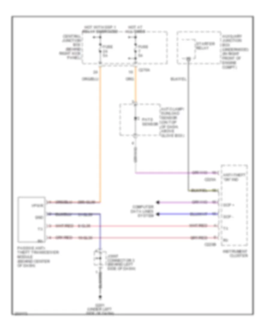
Passive Anti-theft Wiring Diagram for Lincoln LS 2005
List of elements for Passive Anti-theft Wiring Diagram for Lincoln LS 2005:
- 10-gl36
- 29s-gl36
- 31-gl36
- 8-gl36
- Anti-theft "on" ind
- Auto lamp/ sunload sensor (on top of dash, above glove box)
- Auxiliary junction box (underhood) (in right front of engine compt)
- C220a
- C220b
- C270a
- Central junction box (behind right kick panel)
- Computer data lines system
- Fuse 5a
- G201 (under left side of dash)
- Gnd
- Hot at all times
- Hot with ssp 1 relay energized
- Instrument cluster
- Joint connector 3 (behind left side of dash)
- Passive anti- theft transceiver module (behind center of dash)
- Pats sensor
- Scp +
- Scp -
- Starter relay
- Vpwr
BODY CONTROL MODULES
Door Module Wiring Diagram for Lincoln LS 2005
List of elements for Door Module Wiring Diagram for Lincoln LS 2005:
- 10-aa70
- 10-ad18
- 10-aj43
- 29-aj80
- 29s-aa70
- 29s-aj86
- 31-aj80b
- 31s-aa78
- 31s-aa79
- 32-aa11
- 32-ad30
- 32-ad32
- 32-ad7
- 33-aa10
- 33-ad12
- 33-ad7
- 34-ad29
- 34-ad31
- 34-ad8
- 35-ad8
- 4-eg13
- 5-eg13
- 7-aa70
- 7-ad18
- 7-aj7
- 7s-ah27
- 7s-aj20
- 7s-aj49
- 7s-aj50
- 7s-aj51
- 7s-aj52
- 8-aa10
- 8-aa11
- 8-aa70
- 8-ad18
- 8-ah27
- 8-ah31
- 8-ah32
- 8-aj43
- 9-aa70
- 9-ad18
- 91-aj80
- C270d
- C270e
- C501a
- C501c
- C501d
- Central junction box (cjb) (behind right kick panel)
- Computer data lines system
- Door locks system
- Driver door module (in driver's door)
- Fuse 10a
- Fuse 5a
- G203 (behind lower left side of dash)
- Hot at all times
- Hot w/ ssp 1 relay energized
- Memory systems
- Mirrors system
- Power windows system
- S210
Front & Rear Controller Wiring Diagram (1 of 2) for Lincoln LS 2005
List of elements for Front & Rear Controller Wiring Diagram (1 of 2) for Lincoln LS 2005:
- 10-ad19
- 20-dk20
- 29-dk20
- 29s-dk21
- 29s-dk22
- 31-dk20
- 31-dk20a
- 31-dk20b
- 31-dk20c
- 31-dk20d
- 31s-dk21
- 31s-gl46
- 31s-gl47
- 31s-lc3
- 31s-ld9
- 31s-le15
- 31s-le16
- 31s-le22
- 31s-le23
- 31s-lf16
- 31s-lf17
- 31s-lf7
- 31s-lf8
- 31s-lg11
- 31s-lg18
- 32-ad10
- 32-al19
- 33-ad10
- 34-ad11
- 34-al18
- 34-al19
- 35-ad11
- 35-al18
- 4-eg11
- 5-eg11
- 64s-lh5
- 7-ad19
- 7-al18
- 7s-ta33
- 8-aa30
- 8-ad19
- 8-al18
- 8-ce9
- 8-gc21
- 8-gc7
- 8-gc8
- 8-gl7
- 8-ka5
- 9-ad19
- 9-al18
- 9-ce9
- 9-lc34
- 9-lc36
- 91s-gj7
- 91s-gl13
- 91s-le16
- 91s-le23
- Anti-theft system
- C201a
- C201b
- C201c
- C201e
- C201f
- C270c
- C270d
- Central junction box (cjb) (behind right kick panel)
- Computer data lines system
- Door locks system
- Electronic power steering system
- Exterior lights system
- Front electronic module (fem) (on left kick panel)
- Fuse 10a
- Fuse 5a
- G202 (on bottom of left side "a" pillar)
- Headlights system
- Horns system
- Hot at all times
- Hot in run
- Hot w/ ssp 2 relay energized
- Instrument cluster system
- Interior lights system
- Memory systems
- Mirrors system
- Power distribution system
- S233 (w/ parking aid)
- S260
- Seats system
- Shift interlock system
- To rear electronic module (rem) (diagram 2 of 2)
- Trunk, tailgate, fuel doors system
- Wiper/washer system
Front & Rear Controller Wiring Diagram (2 of 2) for Lincoln LS 2005
List of elements for Front & Rear Controller Wiring Diagram (2 of 2) for Lincoln LS 2005:
- 10-aj14
- 10-aj24
- 15-rp12b
- 15s-dk32
- 15s-rg2a
- 29-dk31
- 29s-aa83
- 29s-dk30
- 29s-dk31
- 30-dk30
- 30-dk30a
- 31-dk30a
- 31-dk30b
- 31-dk30c
- 31-dk30d
- 31-dk30e
- 31-dk30f
- 31-dk30g
- 31-dk30h
- 31s-dk30
- 31s-gl12
- 31s-gl19
- 31s-lb25
- 31s-lf11
- 31s-lf12
- 31s-lf20
- 31s-lg12
- 31s-lg14
- 31s-lg16
- 31s-lg19
- 31s-lg21
- 31s-lg6
- 31s-lg9
- 31s-rg2a
- 32-aa1
- 32-aa16
- 33-aa15
- 33-aa2
- 34-aj13
- 34-aj23
- 35-aj13
- 35-aj23
- 4-eg12
- 5-eg12
- 7-aj1
- 8-aa20
- 8-aa21
- 8-ad15
- 8-aj14
- 8-aj24
- 8-ga25
- 8-ga7
- 8-gl20
- 8-gl27
- 8-re32
- 9-ga1
- 91s-gl13
- 91s-hb23
- Anti-theft system
- Battery junction box (bjb) (in luggage compartment, near battery)
- C420a
- C420b
- C420c
- C420d
- C420e
- C420f
- C420g
- Computer data lines system
- Defogger system
- Door locks system
- Engine controls system
- Exterior lights system
- From front electronic b module (fem) (diagram 1 of 2)
- From splice s260 (diagram 1 of 2)
- Fuse 15a
- Fuse 20a
- G401 (at right rear of luggage compartment)
- Hot at all times
- Hot w/ ssp 4 relay energized
- Interior lights system
- Mirrors system
- Power distribution system
- Power windows system
- Rear electronic module (rem) (in right side of luggage compartment)
- Trunk, tailgate, fuel doors system
- Warning system
COMPUTER DATA LINES
Computer Data Lines Wiring Diagram for Lincoln LS 2005
List of elements for Computer Data Lines Wiring Diagram for Lincoln LS 2005:
- (below left front seat) g302
- (not used)
- 4-ah80
- 4-cf6
- 4-cg16
- 4-ec7
- 4-ee1
- 4-eg11
- 4-eg12
- 4-eg13
- 4-eg17
- 4-fa1
- 4-fa10
- 4-gn10
- 4-hc21
- 4-hc22
- 4-re8
- 5-ah80
- 5-cf6
- 5-cg16
- 5-ec7
- 5-eg11
- 5-eg12
- 5-eg13
- 5-eg17
- 5-fa10
- 5-re8
- 7-re14
- Abs control module (right front side of engine compt)
- Abs test connector (in left rear of engine compt)
- Audio unit (behind center of dash)
- Auxiliary junction box (ajb) (interior) (under left side of dash)
- Breakout to g203)
- C175b
- C201c
- C220b
- C228a
- C270a
- C283a
- C283b
- C283c
- C283d
- C290c
- C3031a
- C3036a
- C310a
- C341c
- C4014b
- C4205b
- C420b
- C501a
- Can+
- Can-
- Central junction box (cjb) (behind right kick panel)
- Data link connector (dlc) (under left side of dash)
- Driver door module (in driver's door)
- Driver seat module (w/ memory) (under driver's seat)
- Driver side climate controlled seat module (under driver's seat)
- Electronic automatic temperature control module (eatc) (behind center of dash)
- Electronic park brake module (at left side of luggage compt)
- Feps
- Front electronic module (on left kick panel)
- Fuse 10a
- G201 (under left side of dash)
- Hot at all times
- Instrument cluster
- Iso
- Joint connector 1 (behind right side of dash)
- Joint connector 4 (behind left side of dash)
- Joint connector 5 (at left side of luggage compt)
- Navigation module (on package tray)
- Nca
- Parking aid module (pam) (on left rear of package tray)
- Passenger side climate controlled seat module (under right front seat)
- Powertrain control module (pcm) (right rear of engine compt)
- Rear electronic module (rem) (in right side of luggage compt)
- Restraints control module (on center floor pan)
- S209 (in body main harness, near
- S350
- Scp +
- Scp -
- Scp+
- Scp-
- System
- Ubp
- W/ navigation system
- W/o navigation
- W/o navigation system
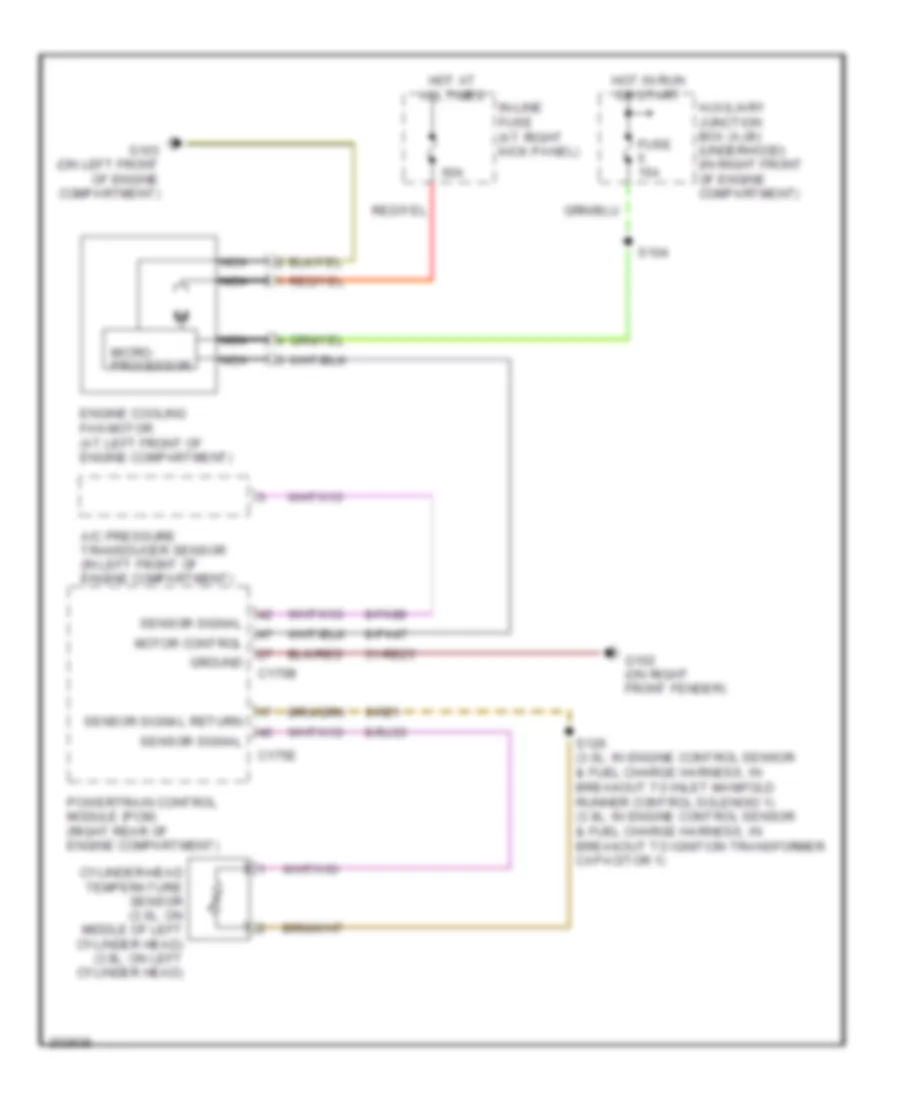
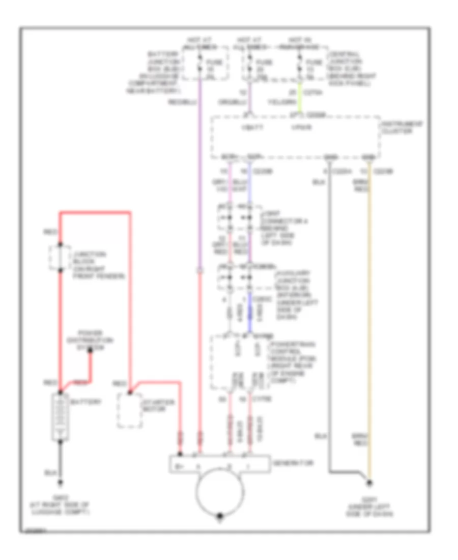
COOLING FAN
Cooling Fan Wiring Diagram for Lincoln LS 2005
List of elements for Cooling Fan Wiring Diagram for Lincoln LS 2005:
- 31-re25
- 60a
- 8-fa88
- 8-pa47
- 8-rj33
- 9-re1
- A/c pressure transducer sensor (in left front of engine compartment)
- Auxiliary junction box (ajb) (underhood) (in right front of engine compartment)
- C175b
- C175e
- Cylinder-head temperature sensor (3.0l: on middle of left cylinder head) (3.9l: on left cylinder head)
- Engine cooling fan motor (at left front of engine compartment)
- Fuse 15a
- G102 (on right front fender)
- G103 (on left front of engine compartment)
- Ground
- Hot at all times
- Hot in run or start
- In-line fuse (at right kick panel)
- Micro- processor
- Motor control
- Nca
- Powertrain control module (pcm) (right rear of engine compartment)
- S104
- S126 (3.0l: in engine control sensor & fuel charge harness, in breakout to inlet manifold runner control solenoid 1) (3.9l: in engine control sensor & fuel charge harness, in breakout to ignition transformer capacitor 1)
- Sensor signal
- Sensor signal return
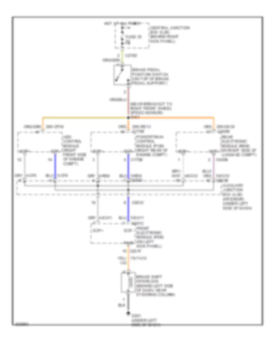
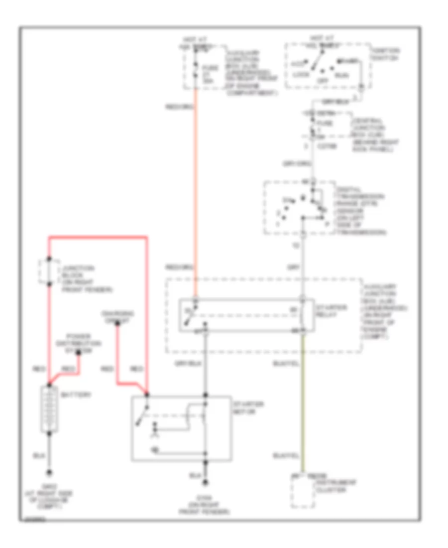
CRUISE CONTROL
Cruise Control Wiring Diagram for Lincoln LS 2005
List of elements for Cruise Control Wiring Diagram for Lincoln LS 2005:
- (near breakout to right front wheel speed sensor) s101
- (near breakout to turbine shaft speed sensor) s110
- 15s-re21
- 15s-re25
- 15s-re8
- 29-re8
- 29s-cf1
- 29s-cf2
- 29s-re13
- 31-re25
- 31s-pg24
- 32-rg3
- 33-rg3
- 7-pg24
- 7-rj28
- 8-rj28
- 8-rj39
- 8-ta51
- 9-rj28
- 9-ta1
- Abs control module (right front side of engine compt)
- Auxiliary junction box (ajb) (underhood) (in right front of engine compartment)
- Battery junction box (bjb) (in luggage compartment, near battery)
- Bpp sig
- Bps sig
- Brake pedal position switch (on top of brake pedal support)
- Brake pressure switch (on top of brake pedal support)
- C175b
- C175e
- C175t
- C218b
- C270c
- C270d
- Cancel
- Central junction box (cjb) (behind right kick panel)
- Electronic throttle control (etc) motor (on top front of engine)
- Engine controls system
- Etc+/-
- Fuse 15a
- Fuse 30a
- Fuse 5a
- G102 (on right front fender)
- Gnd
- Hot at all times
- Hot in start or run
- Interior lights system
- Nca
- Off
- Oss sig
- Output shaft speed (oss) sensor (on left side of transmission)
- Pcm power relay
- Powertrain control module (pcm) (right rear of engine compartment)
- Red
- Rest
- Resume
- S102 (in dash panel to headlamp junction harness, near breakout to right front wheel speed sensor)
- S111 (in dash panel to headlamp junction harness, near breakout to underhood auxiliary junction box)
- S112
- S204
- S226 (near breakout to glove box lamp)
- Set+
- Set-
- Sig rtn
- Sound systems
- Speed control switch
- Steering wheel assembly
- Throttle position sensor (tps) (3.0l: on right side of engine) (3.9l: on top front of engine)
- Vbatt
- Vpwr
- Vref
- W/ stability assist
- W/o stability assist
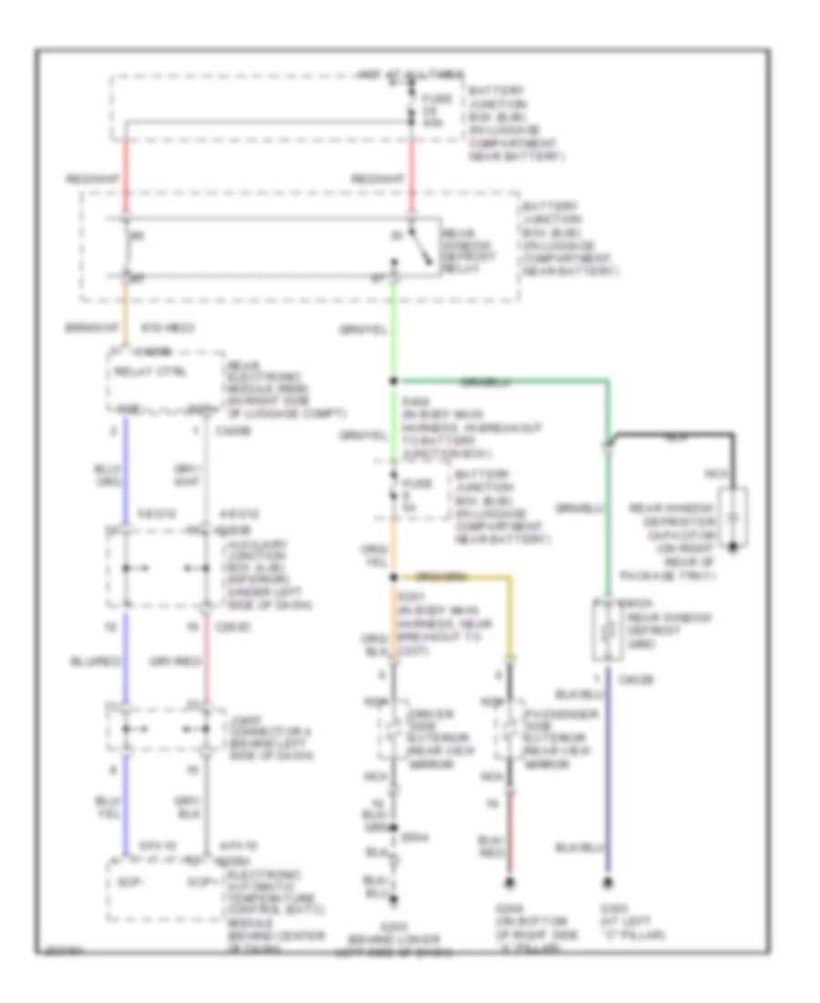
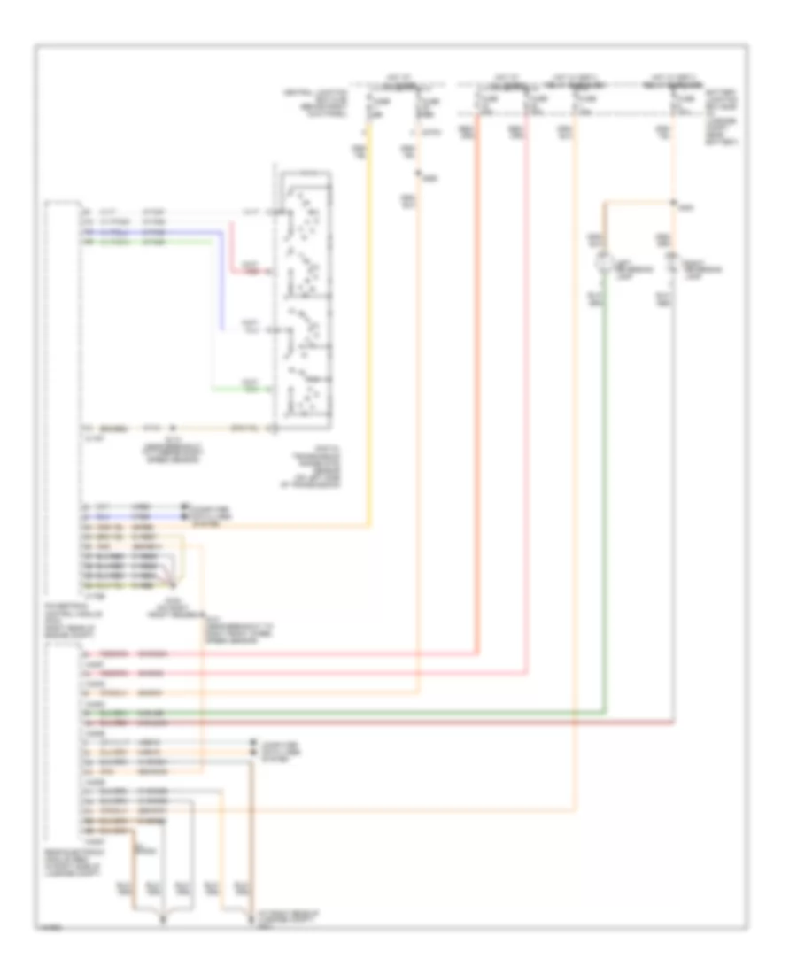
DEFOGGERS
Rear Defogger & Heated Mirrors Wiring Diagram for Lincoln LS 2005
List of elements for Rear Defogger & Heated Mirrors Wiring Diagram for Lincoln LS 2005:
- 4-eg12
- 4-fa10
- 5-eg12
- 5-fa10
- 91s-hb23
- Auxiliary junction box (ajb) (interior) (under left side of dash)
- Battery junction box (bjb) (in luggage compartment, near battery)
- C228a
- C237)
- C283b
- C283d
- C402a
- C402b
- C420b
- Driver side exterior rear view mirror
- Electronic automatic temperature control (eatc) module (behind center of dash)
- Fuse 40a
- Fuse 5a
- G203 (behind lower left side of dash)
- G204 (on bottom of right side ``a" pillar)
- G303 (at left ``c" pillar)
- Hot at all times
- Joint connector 4 (behind left side of dash)
- Nca
- Passenger side exterior rear view mirror
- Rear electronic module (rem) (in right side of luggage compt)
- Rear window defrost grid
- Rear window defrost relay
- Rear window defroster capacitor (on right rear of package tray)
- Relay ctrl
- S404 (in body main harness, in breakout to battery junction box)
- S504
- Scp+
- Scp-
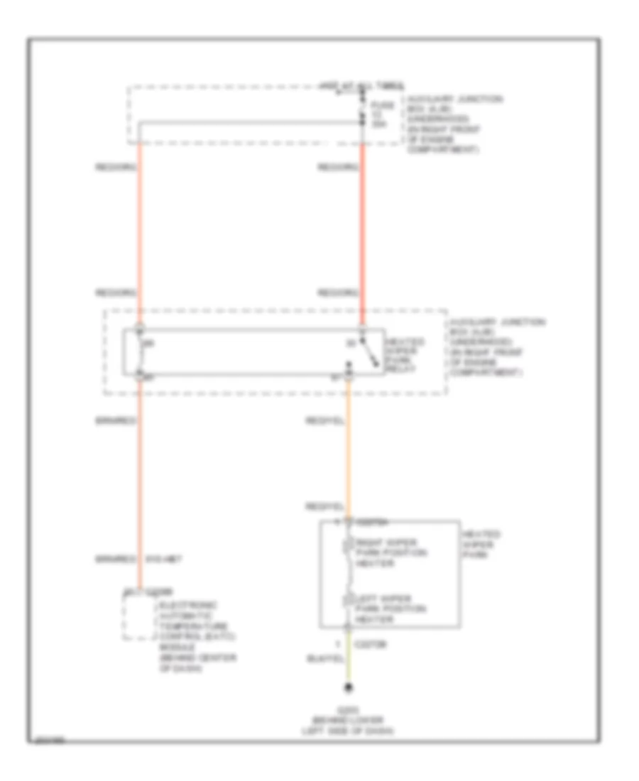
Wiper Deicer Wiring Diagram for Lincoln LS 2005
List of elements for Wiper Deicer Wiring Diagram for Lincoln LS 2005:
- Auxiliary junction box (ajb) (underhood) (in right front of engine compartment)
- C2272a
- C2272b
- C228b
- Electronic automatic temperature control (eatc) module (behind center of dash)
- Fuse 30a
- G203 (behind lower left side of dash)
- Heated wiper park
- Heated wiper park relay
- Hot at all times
- Left wiper park position heater
- Right wiper park position heater
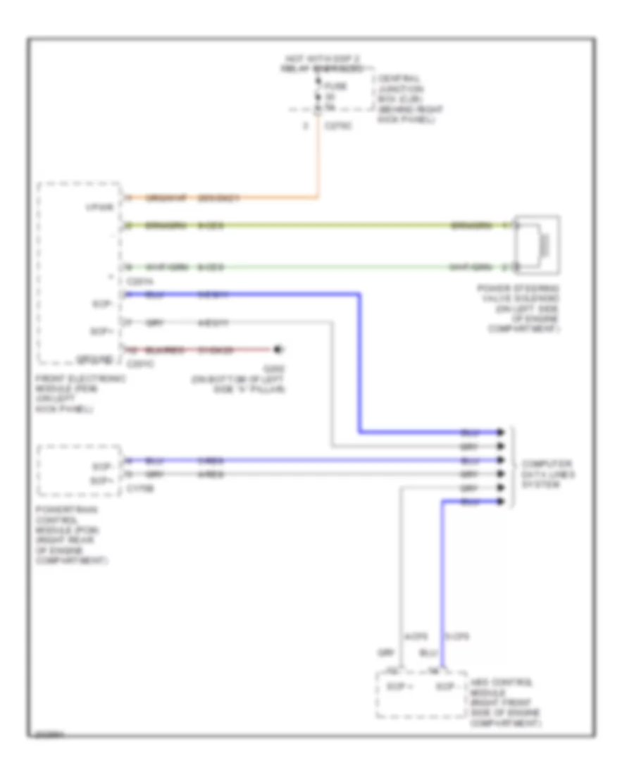
ELECTRONIC POWER STEERING
Electronic Power Steering Wiring Diagram for Lincoln LS 2005
List of elements for Electronic Power Steering Wiring Diagram for Lincoln LS 2005:
- 29s-dk21
- 31-dk20
- 4-cf6
- 4-eg11
- 4-re8
- 5-cf6
- 5-eg11
- 5-re8
- 8-ce9
- 9-ce9
- Abs control module (right front side of engine compartment)
- C175b
- C201a
- C201c
- C270c
- Central junction box (cjb) (behind right kick panel)
- Computer data lines system
- Front electronic module (fem) (on left kick panel)
- Fuse 5a
- G202 (on bottom of left side "a" pillar)
- Ground
- Hot with ssp 2 relay energized
- Power steering valve solenoid (on left side of engine compartment)
- Powertrain control module (pcm) (right rear of engine compartment)
- Scp +
- Scp -
- Scp+
- Scp-
- Vpwr
Power Steering Column Wiring Diagram for Lincoln LS 2005
List of elements for Power Steering Column Wiring Diagram for Lincoln LS 2005:
- 29-al12
- 31-al11
- 32-al6
- 33-al6
- 34-al7
- 35-al7
- 4-eg8
- 5-eg8
- 7-al17
- 8-al10
- 8-al16
- 8-al17
- 9-al10
- 9-al17
- C220a
- C220b
- C220c
- C270a
- Central junction box (cjb) (behind right kick panel)
- Computer data lines system
- Down
- Fuse 19 15a
- G201 (under left side of dash)
- Hot at all times
- In+ out-
- In- out+
- Instrument cluster
- Out
- Scp+
- Scp-
- Sig rtn
- Steering column position motor (on steering column)
- Steering column position sensor (on steering column)
- Steering column position switch (on steering column)
- Telescope
- Tilt
- Up+ down-
- Up- down+
- Vbatt
- Vref
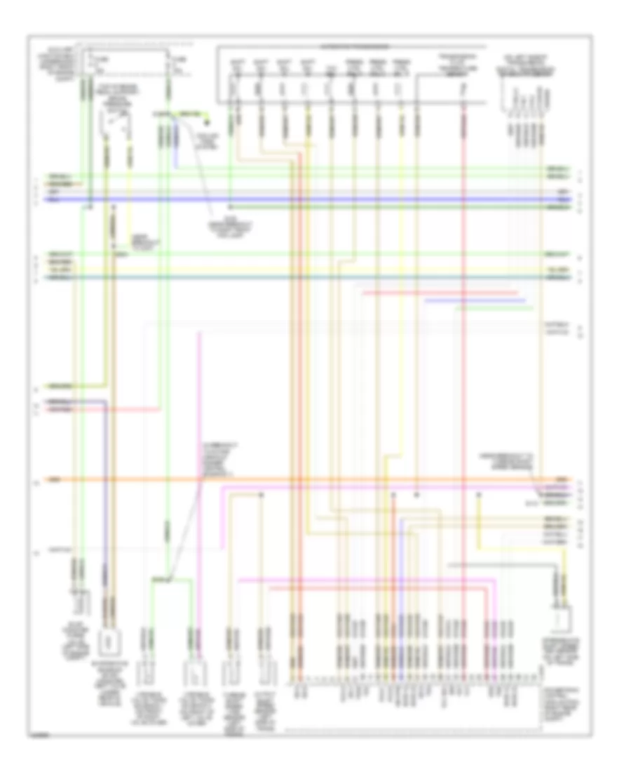
ENGINE PERFORMANCE
3.0L
3.0L, Engine Performance Wiring Diagram (1 of 4) for Lincoln LS 2005
List of elements for 3.0L, Engine Performance Wiring Diagram (1 of 4) for Lincoln LS 2005:
- (in body main harness, near breakout to c291)
- (in breakout to battery junction box) s403
- (near breakout to ambient air temperature sensor)
- (near breakout to right front wheel speed
- (near breakout to right front wheel speed sensor)
- (near breakout to underhood auxiliary junction box)
- (on right front fender) g102
- (on right radiator support) g101
- 15s-re21
- 15s-re25
- 15s-re8
- 29-re8
- 29s-re13
- 31-re21
- 31-re25
- 31-re26
- 31-re8
- 31s-pg24
- 4-ec7
- 4-re8
- 5-ec7
- 5-re8
- 7-pg24
- 7-re14
- 7-re8
- 7-rj30
- 7-rj35
- 8-fa88
- 8-pa47
- 8-re32
- 8-rj10
- 8-rj13
- 8-rj17
- 8-rj22
- 8-rj30
- 8-rj35
- 8-rj36
- 8-ta21
- 8-ta67
- 8-ta68
- 9-re8
- 9-rj22
- 9-rj30
- 91-re27
- 91s-fa79
- 91s-rl25
- 91s-rl3
- A/c pressure transducer sensor (in left front of engine compt)
- Ac clutch
- Ac press
- Air conditioning system
- Auxiliary junction box (underhood) (in right front of engine compt)
- Battery junction box (bjb) (in luggage compt, near battery)
- Brake in
- C175b
- C270b
- C270c
- C270d
- Can +
- Can -
- Central junction box (cjb) (behind right kick panel)
- Cooling fans system
- Cops & heated oxygen sensor relay
- Cruise control system
- Data link connector (under left side of dash)
- Electronic throttle control module (behind left side of dash)
- Etc ref
- Etc sig
- Etc sig rtn
- Etc signal
- Evap ctrl
- Evap purge
- Fan ctrl
- Fuel pump motor diode
- Fuel tank pressure transducer sensor (under rear of vehicle)
- Fuse 30a
- Fuse 5a
- G102 (on right front fender)
- Ground
- Hot at all times
- Hot in run
- Hot in run or start
- Iat sens
- Inertia fuel shut-off (ifs) switch (inside left kick panel)
- Maf rtn
- Maf sig
- Man mode (+)
- Man mode (-)
- Mass air flow (maf) sensor (on air intake assembly)
- Mt sw +
- Mt sw -
- O/d cancel sw
- Od off
- Pcm power diode
- Pcm power relay
- Power
- Powertrain control module (pcm) (right rear of engine compt)
- Prg sig
- Red
- Ref volt
- Rem sig
- Rest mod
- S102
- S103
- S111
- S112
- S113
- S138 (near breakout to underhood auxiliary junction box)
- S211
- S220
- S328 (near breakout to yaw velocity sensor)
- Scp +
- Scp -
- Sensor)
- Signal rtn
- Spd sw
- Tank press
- Transmission shift selector (a/t) (on center of floor pan)
- Voltage
3.0L, Engine Performance Wiring Diagram (2 of 4) for Lincoln LS 2005
List of elements for 3.0L, Engine Performance Wiring Diagram (2 of 4) for Lincoln LS 2005:
- (in breakout to intake manifold runner control solenoid 1)
- (near breakout to c237)
- (on left side of transmission) digital transmission range (dtr) sensor
- (on top of brake pedal support) brake pressure switch
- 8-rj25
- 8-rj26
- 8-ta26
- 8-ta27
- 8-ta37
- 8-ta38
- 8-ta39
- 8-ta40
- 8-ta51
- 8-ta74
- 9-ta1
- 91s-rj25
- 91s-rj26
- 91s-ta23
- 91s-ta24
- 91s-ta47
- 91s-ta63
- 91s-ta64
- 91s-ta65
- 91s-ta69
- 91s-ta70
- Automatic transmission
- Auxiliary junction box (underhood) (in right front of engine compt)
- C175t
- Cooling fans system
- Evap canister purge valve (in left side of engine compt)
- Evaporative emission (evap) canister vent valve (under rear of vehicle)
- Fuse 15a
- Ho2s 12
- Ho2s 22
- Intermediate shaft speed (iss) sensor (on left side of transmission)
- Iss
- Oss
- Output shaft speed (oss) sensor (on left side of trans)
- P,3/4,2,1
- P,n,1
- P,r,2
- P,r,n,3/4
- Pcs a
- Pcs b
- Pcs c
- Power
- Powertrain control module (pcm) (right rear of engine compt)
- Press ctrl sol a
- Press ctrl sol b
- Press ctrl sol c
- S104
- S105 (near breakout to right front fog lamp)
- S110 (near breakout to tss sensor)
- S125
- S204
- Shift sol a
- Shift sol b
- Shift sol c
- Shift sol d
- Sig rtn
- Ss a
- Ss b
- Ss c
- Ss d
- Tcc sol
- Tft
- Tr1
- Tr2
- Tr3a
- Tr4
- Transmission fluid temperature sensor
- Tss
- Turbine shaft speed (tss) sensor (on left side of trans)
- Variable valve timing solenoid 1 (on front of right valve cover)
- Variable valve timing solenoid 2 (on front of left valve cover)
3.0L, Engine Performance Wiring Diagram (3 of 4) for Lincoln LS 2005
List of elements for 3.0L, Engine Performance Wiring Diagram (3 of 4) for Lincoln LS 2005:
- "c" pillar)
- (in breakout to c432)
- (in breakout to luggage compt lamp) s434
- (in breakout to rear electronic module)
- (in right side of luggage compt) rear electronic module (rem)
- (near breakout heated oxygen sensor 12)
- (near breakout to fuel tank pressure transducer sensor)
- (near breakout to imrc solenoid 2)
- (near breakout to right front fog lamp) s106
- (near breakout to right front wheel speed sensor)
- (near breakout to underhood auxiliary junction box)
- (right front side of engine compt) (w/ stability) abs control module
- (under left side of dash) auxiliary junction box (interior)
- 15-rp12b
- 15s-dk32
- 15s-rg2a
- 29s-cf1
- 29s-cf2
- 29s-cf58
- 29s-dk30
- 31s-rg2a
- 4-eg12
- 5-eg12
- 8-ga25
- 8-ga7
- 8-re32
- 9-ga1
- Abs control module (w/o stability) (right front side of engine compt)
- Air conditioning system
- Auxiliary junction box (underhood) (in right front of engine compt)
- Battery junction box (bjb) (in luggage compt, near battery)
- Brake pedal position switch (on top of brake pedal support)
- C102a
- C220b
- C270d
- C283b
- C283c
- C283d
- C420a
- C420b
- C420c
- C420d
- Central junction box (cjb) (behind right kick panel)
- Data link connector (dlc) (under left side of dash)
- Engine oil temperature sensor (on left front side of engine)
- Fuel pump relay
- Fuel sender (at left side of luggage compt)
- Fuel tank unit (at left side of luggage compt)
- Fuse 15a
- Fuse 5a
- G300 (at right
- G401 (at right rear of luggage compt)
- Generator
- Heated oxygen sensor (ho2s) 11 (lower right rear of engine, in exhaust manifold)
- Heated oxygen sensor (ho2s) 12 (in exhaust, rear of catalyst)
- Heated oxygen sensor (ho2s) 21 (lower left rear of engine, in exhaust manifold)
- Heated oxygen sensor (ho2s) 22 (in exhaust, rear of catalyst)
- Hot at all times
- Instrument cluster
- J/c 4 (behind left side of dash)
- Nca
- Power steering pressure switch (in left side of engine compt)
- S101
- S109
- S132
- S135
- S402
- S435
- S436 (in breakout to luggage compt lamp)
- S437
- S438
- S439
- W/ stability
- W/o stability
3.0L, Engine Performance Wiring Diagram (4 of 4) for Lincoln LS 2005
List of elements for 3.0L, Engine Performance Wiring Diagram (4 of 4) for Lincoln LS 2005:
- (in breakout to c192)
- (in breakout to inlet manifold runner control solenoid 1)
- (near breakout to fuel injector 3) s128
- (on top rear of engine) inlet manifold runner control (imrc) solenoid 2
- (on top right rear of engine) inlet manifold runner control (imrc) solenoid 1
- 10-ba25
- 10-rj18
- 10-rj4
- 32-rg3
- 33-rg3
- 7-rj11
- 7-rj28
- 8-ba25
- 8-ce6
- 8-rj11
- 8-rj12
- 8-rj14
- 8-rj15
- 8-rj18
- 8-rj2
- 8-rj28
- 8-rj3
- 8-rj33
- 8-rj39
- 8-rj4
- 8-rj6
- 8-rl26
- 8-rl27
- 9-re1
- 9-rj28
- 91s-rj14
- 91s-rj15
- 91s-rl10
- 91s-rl11
- 91s-rl12
- 91s-rl13
- 91s-rl14
- 91s-rl15
- 91s-rl20
- 91s-rl40
- 91s-rr10
- 91s-rr5
- 91s-rr6
- 91s-rr7
- 91s-rr8
- 91s-rr9
- C175e
- Camshaft position sensor 1 (on top front of engine)
- Camshaft position sensor 2 (on top of engine)
- Ckp +
- Ckp -
- Cmp1 sens
- Cmp2 sens
- Coil 1
- Coil 2
- Coil 3
- Coil 4
- Coil 5
- Coil 6
- Coils on plugs
- Crankshaft position sensor (lower left front of engine)
- Cyl temp
- Cylinder head temperature sensor (on middle of left cylinder head)
- Dc volt
- Electronic throttle control (etc) motor (on top front of engine)
- Eot sig
- Etc mtr
- Fuel injectors
- Fuel rail
- Fuel rail pressure transducer sensor (on top rear of engine)
- Fuel rail temperature sensor (on upper left front of engine)
- G102 (on right front fender)
- Gen
- Gen com
- Ho2s 11
- Ho2s 21
- Ignition transformer capacitor 1 (in left rear of engine compt)
- Ignition transformer capacitor 2 (in right rear of engine compt)
- Imrc 1
- Imrc 2
- Inj 1
- Inj 2
- Inj 3
- Inj 4
- Inj 5
- Inj 6
- Knock sensor 1 (on top right side of engine)
- Ks 1 feed
- Ks 1 rtn
- Nca
- Powertrain control module (pcm) (right rear of engine compt)
- Psp sw fd
- Ref volt
- Return
- S117
- S124
- S126
- S131 (in breakout to ignition transformer capacitor 2)
- S134
- Temp sig
- Throttle position sensor (tps) (on right side of engine)
- Tps
- Tps rtn
- Tps sig
- Vvt sol1
- Vvt sol2
3.9L
3.9L, Engine Performance Wiring Diagram (1 of 4) for Lincoln LS 2005
List of elements for 3.9L, Engine Performance Wiring Diagram (1 of 4) for Lincoln LS 2005:
- (in body main harness, near breakout to c291)
- (in breakout to battery junction box) s403
- (near breakout to ambient air temperature sensor)
- (near breakout to right front wheel speed
- (near breakout to right front wheel speed sensor)
- (near breakout to underhood auxiliary junction box)
- (on right front fender)
- (on right front fender) g102
- (on right radiator support)
- 15s-re21
- 15s-re25
- 15s-re8
- 29-re8
- 29s-re13
- 31-re21
- 31-re25
- 31-re26
- 31-re8
- 31s-pg24
- 4-ec7
- 4-re8
- 5-ec7
- 5-re8
- 7-pg24
- 7-re14
- 7-re8
- 7-rj30
- 7-rj35
- 8-fa88
- 8-pa47
- 8-re32
- 8-rj10
- 8-rj13
- 8-rj17
- 8-rj22
- 8-rj30
- 8-rj35
- 8-rj36
- 8-ta21
- 8-ta67
- 8-ta68
- 9-re8
- 9-rj22
- 9-rj30
- 91-re27
- 91s-fa79
- 91s-rl25
- 91s-rl3
- A/c pressure transducer sensor (on left front of engine compt)
- Ac clutch
- Ac press
- Air conditioning system
- Auxiliary junction box (underhood) (in right front of engine compt)
- Battery junction box (in luggage compt, near battery)
- Brake in
- C175b
- C270b
- C270c
- C270d
- Can +
- Can -
- Central junction box (cjb) (behind right kick panel)
- Cooling fans system
- Cops & heated oxygen sensor relay
- Cruise control system
- Data link connector (under left side of dash)
- Electronic throttle control module (behind left side of dash)
- Etc ref
- Etc sig
- Etc sig rtn
- Etc signal
- Evap ctrl
- Evap purge
- Fan ctrl
- Fuel pump motor diode
- Fuel tank pressure transducer sensor (under rear of vehicle)
- Fuse 30a
- Fuse 5a
- G101
- G102
- Ground
- Hot at all times
- Hot in run
- Hot in run or start
- Iat sens
- Inertia fuel shut-off (ifs) switch (inside left kick panel)
- Maf rtn
- Maf sig
- Man mode (+)
- Man mode (-)
- Mass air flow (maf) sensor (on air intake assembly)
- Mt sw +
- Mt sw -
- O/d cancel sw
- Od off
- Pcm power diode
- Pcm power relay
- Power
- Powertrain control module (pcm) (right rear of engine compt)
- Prg sig
- Red
- Ref volt
- Rem sig
- Rest mod
- S102
- S103
- S111
- S112
- S113
- S138 (near breakout to underhood auxiliary junction box)
- S211
- S220
- S328 (near breakout to yaw velocity sensor)
- Scp +
- Scp -
- Sensor)
- Signal rtn
- Spd sw
- Tank press
- Transmission shift selector (a/t) (on center of floor pan)
- Voltage
3.9L, Engine Performance Wiring Diagram (2 of 4) for Lincoln LS 2005
List of elements for 3.9L, Engine Performance Wiring Diagram (2 of 4) for Lincoln LS 2005:
- (in breakout to intake manifold runner control solenoid 1)
- (near breakout to c237)
- (near breakout to turbine shaft speed sensor)
- (on left side of transmission) digital transmission range (dtr) sensor
- (top of brake pedal support) brake pressure switch
- 8-rj25
- 8-rj26
- 8-ta26
- 8-ta27
- 8-ta37
- 8-ta38
- 8-ta39
- 8-ta40
- 8-ta51
- 8-ta74
- 9-ta1
- 91s-rj25
- 91s-rj26
- 91s-ta23
- 91s-ta24
- 91s-ta47
- 91s-ta63
- 91s-ta64
- 91s-ta65
- 91s-ta69
- 91s-ta70
- Automatic transmission
- Auxiliary junction box (underhood) (right front of engine compt)
- C175t
- Cooling fans system
- Evap canister purge valve (left side of engine compt)
- Evaporative emission (evap) canister vent valve (under rear of vehicle)
- Fuse 15a
- Ho2s 12
- Ho2s 22
- Intermediate shaft speed (iss) sensor (on left side of trans)
- Iss
- Oss
- Output shaft speed sensor (left side of trans)
- P,3/4,2,1
- P,n,1
- P,r,2
- P,r,n,3/4
- Pcs a
- Pcs b
- Pcs c
- Power
- Powertrain control module (pcm) (right rear of engine compt)
- Press ctrl sol a
- Press ctrl sol b
- Press ctrl sol c
- S104
- S105 (near breakout to right front fog lamp)
- S110
- S125
- S204
- Shift sol a
- Shift sol b
- Shift sol c
- Shift sol d
- Sig rtn
- Ss a
- Ss b
- Ss c
- Ss d
- Tcc sol
- Tft
- Tr1
- Tr2
- Tr3a
- Tr4
- Transmission fluid temperature sensor
- Tss
- Turbine shaft speed (tss) sensor (left side of trans)
- Variable valve timing solenoid 1 (on front of right valve cover)
- Variable valve timing solenoid 2 (on front of left valve cover)
3.9L, Engine Performance Wiring Diagram (3 of 4) for Lincoln LS 2005
List of elements for 3.9L, Engine Performance Wiring Diagram (3 of 4) for Lincoln LS 2005:
- "c" pillar)
- (in breakout to c432)
- (in breakout to luggage compt lamp) s434
- (in breakout to rear electronic module)
- (in engine control sensor & fuel charge harness, in breakout to c140)
- (in right side of luggage compt) rear electronic module (rem)
- (near breakout to fuel tank pressure transducer sensor)
- (near breakout to heated oxygen sensor
- (near breakout to right front fog lamp) s106
- (near breakout to right front wheel speed
- (right front side of engine compt) (w/ stability) abs control module
- (under left side of dash) auxiliary junction box (interior)
- 12)
- 15-rp12b
- 15s-dk32
- 15s-rg2a
- 29s-cf1
- 29s-cf2
- 29s-dk30
- 31s-rg2a
- 4-eg12
- 5-eg12
- 8-ga25
- 8-ga7
- 8-re32
- 9-ga1
- Abs control module (w/o stability) (right front side of engine compt)
- Air conditioning system
- Auxiliary junction box (underhood) (in right front of engine compt)
- Battery junction box (bjb) (in luggage compt, near battery)
- C220b
- C251
- C283b
- C283c
- C283d
- C420a
- C420b
- C420c
- C420d
- Camshaft position sensor 2 (top left rear of engine)
- Data link connector (dlc) (under left side of dash)
- Engine oil temperature sensor (on lower front of engine)
- Fuel pump relay
- Fuel rail temperature sensor (top right rear of engine)
- Fuel sender (left side of luggage compt)
- Fuel tank unit (left side of luggage compt)
- Fuse 15a
- G300 (right
- G401 (at right rear of luggage compt)
- Generator
- Heated oxygen sensor (ho2s) 11 (right exhaust manifold)
- Heated oxygen sensor (ho2s) 12 (in exhaust, rear of catalyst)
- Heated oxygen sensor (ho2s) 21 (left exhaust manifold)
- Heated oxygen sensor (ho2s) 22 (in exhaust, rear of catalyst)
- Hot at all times
- Instrument cluster
- J/c 4 (behind left side of dash)
- Nca
- Power steering pressure switch (left side of engine compt)
- S101
- S109
- S132
- S135 (near breakout to underhood auxiliary junction box)
- S402
- S435
- S436 (in breakout to luggage compt lamp)
- S437
- S438
- S439
- Sensor)
- W/ stability
- W/o stability
3.9L, Engine Performance Wiring Diagram (4 of 4) for Lincoln LS 2005
List of elements for 3.9L, Engine Performance Wiring Diagram (4 of 4) for Lincoln LS 2005:
- (in breakout to coil on plug 8) s129
- (in breakout to fuel injector 8) s130
- (in breakout to ignition transformer
- 10-ba25
- 10-rj18
- 10-rj19
- 10-rj4
- 32-rg3
- 33-rg3
- 7-rj28
- 7-rn11
- 8-ba25
- 8-ce6
- 8-rj11
- 8-rj12
- 8-rj14
- 8-rj15
- 8-rj18
- 8-rj19
- 8-rj2
- 8-rj20
- 8-rj28
- 8-rj3
- 8-rj33
- 8-rj39
- 8-rj4
- 8-rj6
- 8-rj7
- 8-rl26
- 8-rl27
- 9-re1
- 9-rj28
- 91s-rj14
- 91s-rj15
- 91s-rl10
- 91s-rl11
- 91s-rl12
- 91s-rl13
- 91s-rl14
- 91s-rl15
- 91s-rl16
- 91s-rl17
- 91s-rl7
- 91s-rr10
- 91s-rr11
- 91s-rr12
- 91s-rr5
- 91s-rr6
- 91s-rr7
- 91s-rr8
- 91s-rr9
- Brake pedal position switch (on top of brake pedal support)
- C175e
- C270d
- Camshaft position sensor 1 (right rear of cylinder head)
- Capacitor 1)
- Central junction box (cjb) (behind right kick panel)
- Ckp +
- Ckp -
- Cmp1 sens
- Cmp2 sens
- Coil 1
- Coil 2
- Coil 3
- Coil 4
- Coil 5
- Coil 6
- Coil 7
- Coil 8
- Coils on plugs
- Crankshaft position sensor (lower left side of engine)
- Cyl temp
- Cylinder head temperature sensor (left cylinder head)
- Dc volt
- Egr system module (upper right front of engine)
- Electronic throttle control motor (on top front of engine)
- Eot sig
- Ept ctrl
- Ept sens
- Ept sig
- Etc mtr
- Fuel injectors
- Fuel rail
- Fuel rail pressure transducer sensor (top right side of engine)
- Fuse 5a
- G102 (right front fender)
- Gen
- Gen com
- Ho2s 11
- Ho2s 21
- Hot at all times
- Ignition trans- former capacitor 1 (left rear engine compt)
- Ignition trans- former capacitor 2 (right rear engine compt)
- Inj 1
- Inj 2
- Inj 3
- Inj 4
- Inj 5
- Inj 6
- Inj 7
- Inj 8
- Knock sensor 1 (top right side of engine)
- Knock sensor 2 (top left side of engine)
- Ks 1 feed
- Ks 1 rtn
- Ks 2 feed
- Ks 2 rtn
- Nca
- Powertrain control module (pcm) (right rear of engine compt)
- Psp sw fd
- Ref volt
- Return
- S124
- S126
- S127
- S131 (in breakout to coil on plug 3)
- S150 (near breakout to cmp 1)
- Temp sig
- Throttle position sensor (top front of engine)
- Tps
- Tps rtn
- Tps sig
- Vvt sol1
- Vvt sol2
EXTERIOR LIGHTS
Back-up Lamps Wiring Diagram for Lincoln LS 2005
List of elements for Back-up Lamps Wiring Diagram for Lincoln LS 2005:
- (at right rear of luggage compt) g401
- 29-dk31
- 29-re8
- 29s-dk30
- 29s-dk31
- 29s-re13
- 3/4
- 30-dk30
- 30-dk30a
- 31- dk30g
- 31-dk30d
- 31-dk30e
- 31-dk30f
- 31-dk30h
- 31-re21
- 31-re25
- 31-re26
- 31-re8
- 31s-lg16
- 31s-lg9
- 4-eg12
- 4-re8
- 5-eg12
- 5-re8
- 8-ta37
- 8-ta38
- 8-ta39
- 8-ta40
- 9-ta1
- 91-re27
- Battery junction box (bjb) (in luggage compt, near battery)
- C175b
- C175t
- C270c
- C420b
- C420c
- C420d
- C420e
- C420f
- C420g
- Central junction box (cjb) (behind right kick panel)
- Computer data lines system
- Digital transmission range (dtr) sensor (on left side of transmission)
- Fuse 10a
- Fuse 15a
- Fuse 20a
- Fuse 5a
- G102 (on right front fender)
- Hot at all times
- Hot w/ ssp 3 relay energized
- Hot w/ ssp 4 relay energized
- Left reversing lamp
- N n
- Powertrain control module (pcm) (right rear of engine compt)
- Rear electronic module (rem) (in right side of luggage compt)
- Right reversing lamp
- S101 (near breakout to right front wheel speed sensor)
- S110 (near breakout to turbine shaft speed sensor)
- S260
- S423
Exterior Lamps Wiring Diagram (1 of 2) for Lincoln LS 2005
List of elements for Exterior Lamps Wiring Diagram (1 of 2) for Lincoln LS 2005:
- 29-dk20
- 29s-cf2
- 31-dk20
- 31-dk20a
- 31-dk20b
- 31-dk20c
- 31-dk20d
- 31s-lf16
- 31s-lf17
- 31s-lf7
- 31s-lf8
- 31s-lg11
- 31s-lg18
- 4-eg11
- 5-eg11
- 91s-gl13
- Abs control module (right front side of engine compt)
- Auto
- Brake pedal position switch (on top of brake pedal support)
- C201a
- C201b
- C201c
- C201f
- C220b
- C220c
- C270b
- C270c
- C270d
- Central junction box (cjb) (behind right kick panel)
- Computer data lines system
- Engine control system
- Front electronic module (fem) (on left kick panel)
- Fuse 10a
- Fuse 5a
- G202 (on bottom of left
- Hazard
- Hot at all times
- Hot w/ ssp 1 relay energized
- Instrument cluster
- Left
- Left front park/ turn lamp
- Left head lamp
- Low
- Main light switch
- Multi-function switch (on steering column)
- Off
- Park
- Right
- Right front park/ turn lamp
- Right head lamp
- S101 (near breakout to right front wheel speed sensor)
- S108
- S114
- S260
- Side marker
- Side ``a" pillar)
- W/ stability assist
- W/o stability assist
Exterior Lamps Wiring Diagram (2 of 2) for Lincoln LS 2005
List of elements for Exterior Lamps Wiring Diagram (2 of 2) for Lincoln LS 2005:
- (in breakout to anti-theft luggage compt switch) s408
- 29-dk31
- 29s-dk30
- 31-dk30d
- 31-dk30e
- 31-dk30f
- 31-dk30g
- 31-dk30h
- 31s-lf11
- 31s-lf20
- 31s-lg12
- 31s-lg14
- 31s-lg19
- 31s-lg21
- 31s-lg6
- 91s-gl13
- Battery junction box (bjb) (in luggage compartment, near battery)
- C420a
- C420b
- C420c
- C420d
- C420e
- Fuse 10a
- Fuse 5a
- G401 (at right rear of luggage compartment)
- High mounted stoplamp
- High mounted stoplamp capacitor (on left rear of package tray)
- Hot w/ ssp 3 relay energized
- Hot w/ ssp 4 relay energized
- Left license plate lamp
- Left rear lamp assembly
- Left rear turn lamp
- Nca
- Rear electronic module (rem) (in right side of luggage compt)
- Right license plate lamp
- Right rear lamp assembly
- Right rear turn lamp
- S360 (in body main harness, near breakout to c340)
- S407 (in breakout to right license plate lamp)
- S422
- S423
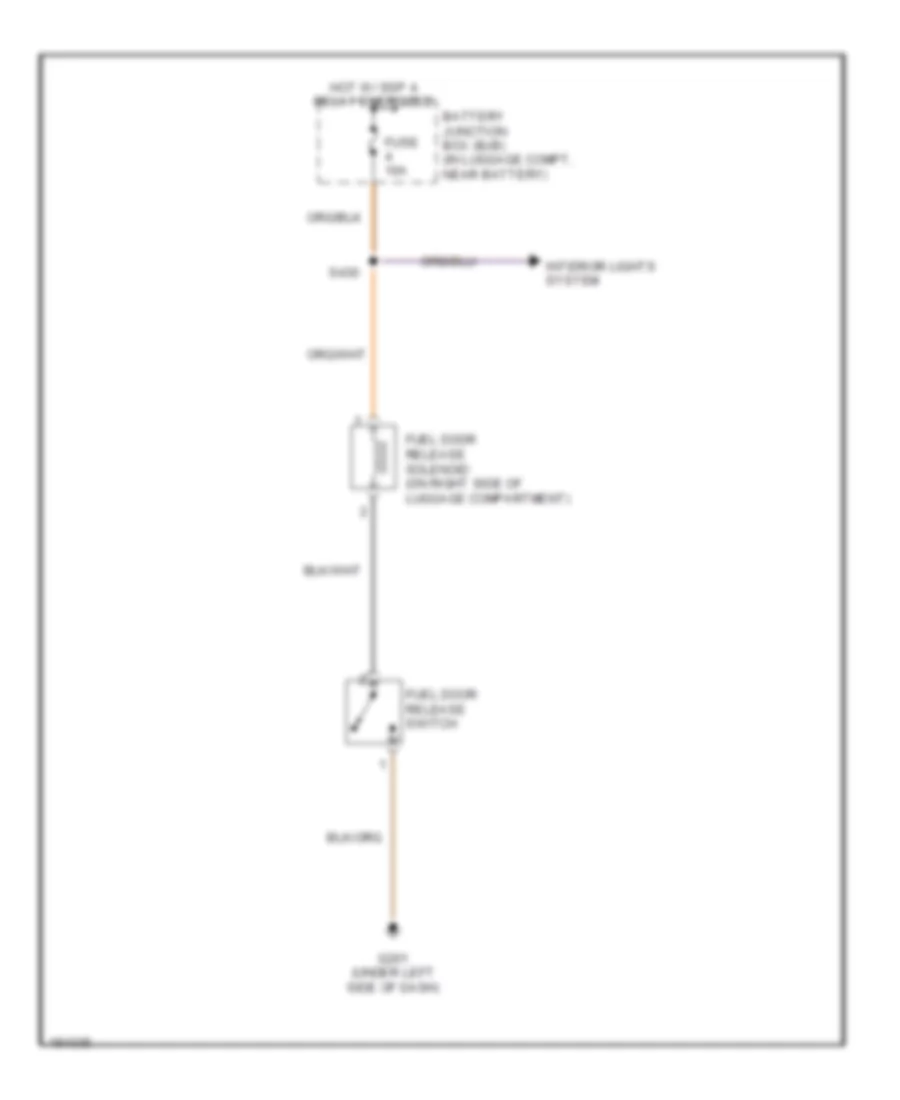
GROUND DISTRIBUTION
Ground Distribution Wiring Diagram (1 of 3) for Lincoln LS 2005
List of elements for Ground Distribution Wiring Diagram (1 of 3) for Lincoln LS 2005:
- (3.9l) auxiliary coolant pump motor
- (in engine control sensor & fuel charge harness, in breakout to powertrain control module) s124
- (radio cdx6) center image amplifier
- (w/ lse ii)
- (w/ navigation system) audio/navigation control unit
- (w/o lse ii)
- A/c clutch field coil
- Abs control module
- Adjustable pedal switch
- Anti-theft hood switch
- Audio unit
- Autolamp/ sunload sensor
- Brake fluid level sensor
- Brake shift interlock
- C175b
- C218b
- C220a
- C220b
- C2253a
- C228a
- C290b
- C310a
- Cops & heated oxygen sensor (h02s) relay
- Data link connector (dlc)
- Electronic automatic temperature control (eatc) module
- Engine cooling fan motor
- Fuel door release switch
- G100 (on left radiator support)
- G101 (on right radiator support)
- G102 (on right front fender)
- G103 (at left front of engine compartment)
- G201 (under left side of dash)
- Glove box lamp
- Horn
- Instrument cluster
- Joint connector 2 (behind right side of dash)
- Joint connector 3 (behind left side of dash)
- Left front fog lamp
- Left headlamp
- Luggage compartment lid release switch
- Main light switch
- Mass air flow (maf) sensor
- Message center switch
- Multi- function switch
- Nca
- Passive anti-theft transceiver module
- Pcm power relay
- Powertrain control module (pcm)
- Restraints control module
- Right front fog lamp
- Right headlamp
- Shorting bar
- Steering wheel assembly
- Underhood auxiliary junction box (ajb) (in right front of engine compartment)
- Washer fluid level switch
- Windshield washer pump motor
- Windshield wiper motor
Ground Distribution Wiring Diagram (2 of 3) for Lincoln LS 2005
List of elements for Ground Distribution Wiring Diagram (2 of 3) for Lincoln LS 2005:
- (in luggage compartment, near battery) battery junction box (bjb)
- (w/ memory) memory set switch
- (w/ memory) passenger side climate controlled seat module
- Abs test connector
- Anti-theft luggage compartment switch
- Breakout to passenger side climate controlled seat module)
- C201a
- C201c
- C2272b
- C3036a
- C3036b
- C501a
- C504a
- Driver door module
- Driver side door lock switch
- Driver side exterior rear view mirror
- Driver side front door lock unit
- Driver side front power window motor
- Driver's side door lock switch)
- Electro- chromatic inside mirror unit
- Exterior rear view mirror switch
- Front electronic module (fem)
- Fuel pump relay
- G104 (on right front fender)
- G202 (on bottom of left side ``a" pillar)
- G203 (behind lower left side of dash)
- G204 (on bottom of right side ``a" pillar)
- G300 (at right ``c" pillar)
- G301 (below right front seat)
- Heated wiper park
- Heater blower control module
- Key pad switch assembly
- Left front map reading lamp switch
- Left rear grab handle lamp
- Left vanity mirror lamp
- Luggage compartment lid ajar switch
- Master window adjust switch
- Nca
- Parking aid disable switch
- Passenger safety belt buckle switch
- Passenger side door lock switch
- Passenger side exterior rear view mirror
- Passenger side front door lock unit
- Passenger side front power window motor
- Passenger side front seat adjust switch
- Passenger side window adjust switch
- Right front lumbar adjust switch
- Right front map reading lamp switch
- Right rear door lock actuator
- Right rear grab handle lamp
- Right rear heated seat module
- Right rear seat heater switch
- Right rear window adjust switch
- Right vanity mirror lamp
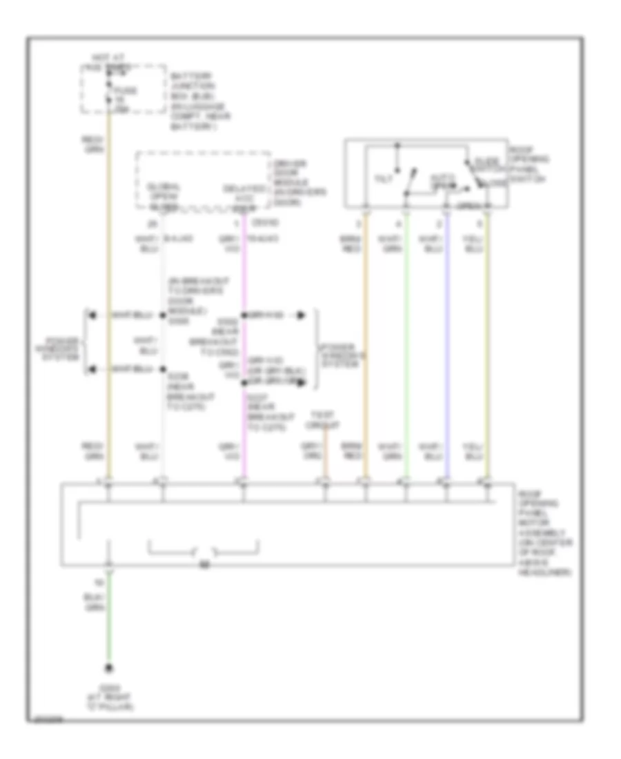
- Roof opening panel motor assembly
- S250 (in body main harness, near breakout to c213)
- S365 (in body main harness, near breakout to g301)
- S504 (in left front door window regulator harness, near breakout to driver's door module)
- S601 (in passenger door trim harness, near breakout to passenger side door lock switch)
- S901 (in interior lamps harness, near breakout to right vanity mirror lamp)
- Shield
- Starter motor
- W/ memory
- W/ memory
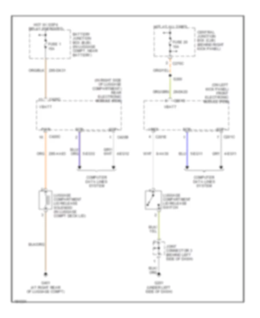
Ground Distribution Wiring Diagram (3 of 3) for Lincoln LS 2005
List of elements for Ground Distribution Wiring Diagram (3 of 3) for Lincoln LS 2005:
- (in body main harness, near breakout to driver's safety belt retractor pretensioner)
- (in seat back control harness, near breakout to driver's side front seat adjust switch)
- (not used)
- (w/ memory) driver seat module
- (w/ memory) driver side climate controlled seat module
- (w/ memory) driver side front seat adjust switch
- (w/ memory) left front lumbar adjust switch
- Ashtray illumination lamp
- Auto park brake release switch
- Battery
- C3031a
- C310a
- C341b
- C341c
- C4014b
- C402b
- C4205a
- C4208b
- C420b
- C420c
- C420d
- C420f
- C420g
- C466a
- Console 1 power point
- Console 2 power point
- Driver safety belt buckle switch
- Driver side front seat adjust switch
- Electronic park brake module
- Front cigar lighter
- G302 (below left front seat)
- G303 (at left ``c" pillar)
- G400 (at left rear of luggage compartment)
- G401 (at right rear of luggage compartment)
- G402 (at right side of luggage compartment)
- Joint connector 5 (at left side of luggage compartment)
- Left rear door lock actuator
- Left rear heated seat module
- Left rear seat heater switch
- Left rear window adjust switch
- Luggage compartment lid release solenoid
- Navigation module
- Nca
- Parking aid module (pam)
- Radio amplifier
- Rear electronic module (rem)
- Rear window defrost grid
- Restraints control module
- S313 (in seat back control harness, in breakout to driver's side front seat adjust switch)
- S320 (in console panel harness, near breakout to traction control switch)
- S350
- S397
- Shield
- Subwoofer amplifier
- Traction control switch
- Transmission shift selector
- W/ climate controlled seats
- W/o memory
HEADLIGHTS
Headlights Wiring Diagram, with High Intensity Gas Discharge Headlights for Lincoln LS 2005
List of elements for Headlights Wiring Diagram, with High Intensity Gas Discharge Headlights for Lincoln LS 2005:
- 10a
- 15a
- 29-dk20
- 31-dk20
- 31-dk20a
- 31-dk20b
- 31-dk20c
- 31-dk20d
- 31s-ld9
- 31s-le15
- 31s-le22
- 31s-lf17
- 31s-lf8
- 4-eg11
- 5-eg11
- 91s-le16
- 91s-le23
- Auto
- Autolamp sensor
- Autolamp signal
- Autolamp/ sunload sensor (on top of dash, above glove box)
- C201a
- C201b
- C201c
- C201f
- C220a
- C220b
- C220c
- C270b
- C270c
- C283c
- C283d
- Central junction box (cjb) (behind right kick panel)
- Exterior lights system
- Flash to pass
- Fog lamp indicator
- Fog lamp relay
- Fog lamp signal
- Fog lamps
- Fog lamps indicator
- Front electronic module (fem) (on left kick panel)
- Fuse
- Fuse 15a
- G100 (on left radiator support)
- G101 (on right radiator support)
- G202 (on bottom of left side "a" pillar)
- Headlamp junction harness, near breakout to right front foglamp) s119
- High beam
- Hot at all times
- Hot with ssp 1 relay energized
- Hot with ssp 2 relay energized
- Instrument cluster
- Interior auxiliary junction box (under left side of dash)
- Joint connector 4 (behind left side of dash)
- Left front fog lamp
- Left headlamp
- Left high intensity discharge headlamp relay
- Low
- Low beam signal
- Main light switch
- Multi-function switch
- Off
- Off signal
- Park
- Park lamp signal
- Red
- Right front fog lamp
- Right headlamp
- Right high intensity discharge headlamp relay
- S137
- S155
- S160
- S260
- Scp bus (+)
- Scp bus (-)
- Signal return
- Underhood auxiliary junction box (in right front of engine compt)
- W/ lse ii
- W/o lse ii
Headlights Wiring Diagram, without High Intensity Gas Discharge Headlights for Lincoln LS 2005
List of elements for Headlights Wiring Diagram, without High Intensity Gas Discharge Headlights for Lincoln LS 2005:
- (in dash panel to headlamp junction harness, near breakout to right front foglamp) s119
- 10a
- 15a
- 29-dk20
- 31-dk20
- 31-dk20a
- 31-dk20b
- 31-dk20c
- 31-dk20d
- 31s-ld9
- 31s-le15
- 31s-le16
- 31s-le22
- 31s-le23
- 31s-lf17
- 31s-lf8
- 4-eg11
- 5-eg11
- Auto
- Autolamp sensor
- Autolamp signal
- Autolamp/ sunload sensor (on top of dash, above glove box)
- C201a
- C201b
- C201c
- C220a
- C220b
- C220c
- C270b
- C270c
- C283c
- C283d
- Central junction box (cjb) (behind right kick panel)
- Exterior lights system
- Flash to pass
- Fog lamp indicator
- Fog lamp relay
- Fog lamp signal
- Fog lamps
- Fog lamps indicator
- Front electronic module (fem) (on left kick panel)
- Fuse
- Fuse 15a
- G100 (on left radiator support)
- G202 (on bottom of left side "a" pillar)
- High beam
- Hot at all times
- Hot with ssp 1 relay energized
- Hot with ssp 2 relay energized
- Instrument cluster
- Interior auxiliary junction box (under left side of dash)
- Joint connector 4 (behind left side of dash)
- Left front fog lamp
- Left headlamp
- Low
- Low beam signal
- Main light switch
- Multi-function switch
- Off
- Off signal
- Park
- Park lamp signal
- Red
- Right front fog lamp
- Right headlamp
- S137
- S260
- Scp bus (+)
- Scp bus (-)
- Signal return
- Underhood auxiliary junction box (in right front of engine compt)
- W/ lse ii
- W/o lse ii
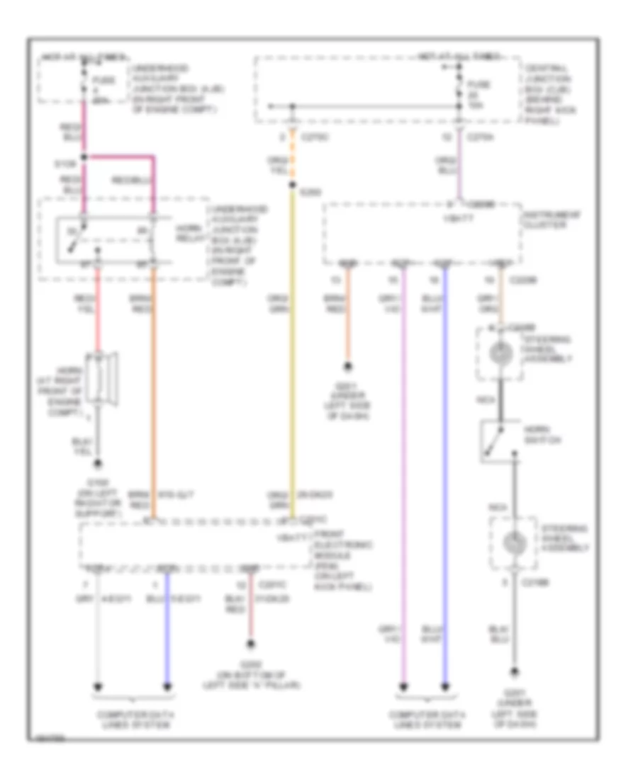
HORN
Horn Wiring Diagram for Lincoln LS 2005
List of elements for Horn Wiring Diagram for Lincoln LS 2005:
- (under left side of dash)
- C201c
- C218b
- C220b
- C270a
- C270c
- Central junction box (cjb) (behind right kick panel)
- Computer data lines system
- Front electronic module (fem) (on left kick panel)
- Fuse 10a
- Fuse 20a
- G100 (on left radiator support)
- G201
- G201 (under left side of dash)
- G202 (on bottom of left side "a" pillar)
- Gnd
- Horn (at right front of engine compt)
- Horn relay
- Horn switch
- Hot at all times
- Instrument cluster
- Nca
- Red
- S139
- S260
- Scp+
- Scp-
- Steering wheel assembly
- Underhood auxiliary junction box (ajb) (in right front of engine compt)
- Vbatt
- Vref
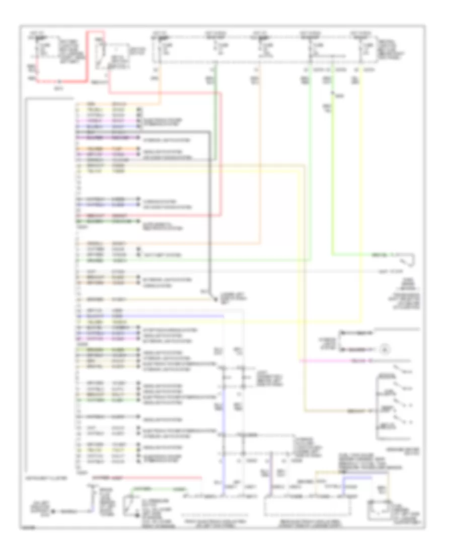
INSTRUMENT CLUSTER
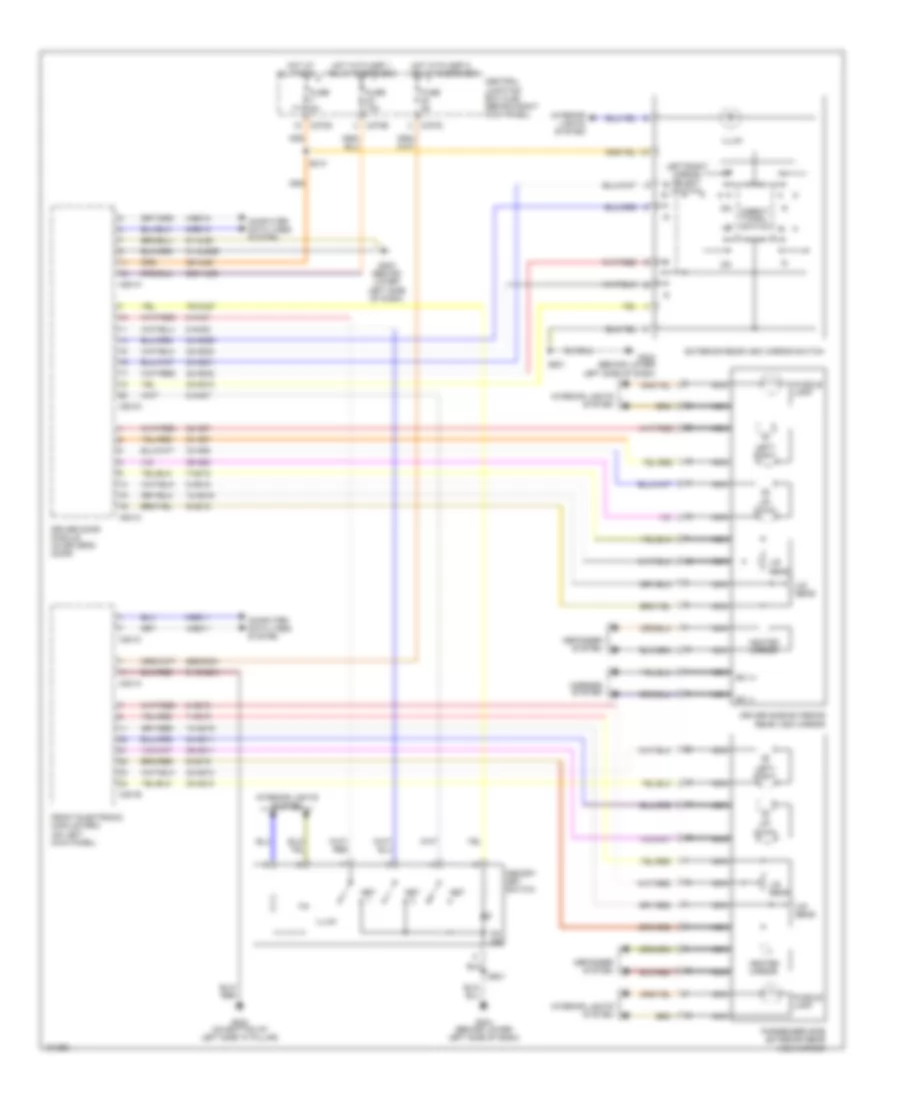
Instrument Cluster Wiring Diagram for Lincoln LS 2005
List of elements for Instrument Cluster Wiring Diagram for Lincoln LS 2005:
- (fuel tank gauge sender harness, near breakout to fuel tank pressure transducer sensor) s402
- (on left radiator support) g100
- (under left side of dash)
- 10-gj9
- 10-gl36
- 10-gl6
- 10-le10
- 10-le21
- 10-le47
- 15-gg14
- 15-ja14b
- 29-al12
- 29-gg11
- 30s-gm7
- 31-al11
- 31s-bb12
- 31s-ja14b
- 32-al6
- 33-al6
- 34-al7
- 35-al7
- 4-eg11
- 4-eg12
- 4-eg8
- 5-eg11
- 5-eg12
- 5-eg8
- 64s-lk29
- 7-al17
- 7-gg25
- 7-ld7
- 75-gg15
- 8-al10
- 8-al16
- 8-al17
- 8-gc21
- 8-gc7
- 8-ge52
- 8-gl36
- 8-ld10
- 8-le10
- 8-le14
- 8-le21
- 8-le42
- 8-lf14
- 8-lg43
- 8-ta34
- 9-al10
- 9-al17
- 9-gg25
- 9-le10
- 9-le29
- 9-lg43
- 91-gg11
- Air conditioning system
- All times
- Anti-theft system
- Battery junction box (bjb) (in luggage compt, near battery)
- Brake fluid level sensor (at left shock tower)
- C201c
- C220a
- C220b
- C220c
- C270a
- C270d
- C283b
- C283c
- C283d
- C420b
- C420c
- C420d
- Central junction box (cjb) (behind right kick panel)
- Electronic power steering system
- Exterior lights system
- Front electronic module (fem) (on left kick panel)
- Fuel
- Fuel sender (at left side of luggage compartment)
- Fuse 10a
- Fuse 15a
- Fuse 20a
- Fuse 5a
- G201
- Headlights system
- Horns system
- Hot at
- Hot in run
- Ignition switch
- Instrument cluster
- Interior auxiliary junction box (under left side of dash)
- Interior lights system
- Joint connector 4 (behind left side of dash)
- Key-in ignition switch
- Message center switch
- Oil pressure switch (3.0l: on lower left side of engine) (3.9l: on lower front of engine)
- Or acc
- Or start
- Park sense switch
- Rear electronic module (rem) (in right side of luggage compt)
- Red
- Reset
- S208
- S213
- Set-up
- Starting/charging system
- Status
- Transmission shift selector (on center of floor pan)
- Warning system
INTERIOR LIGHTS
Courtesy Lamps Wiring Diagram for Lincoln LS 2005
List of elements for Courtesy Lamps Wiring Diagram for Lincoln LS 2005:
- (in left front door) driver side front door lock unit
- (in left rear door) left rear door lock actuator
- (in right rear door) right rear door lock actuator
- (interior) (under left side of dash)
- (near breakout to right front map reading lamp) s902
- 29-dk20
- 29-dk31
- 29s-md7
- 31-dk20a
- 31-dk30h
- 31s-gl12
- 31s-gl19
- 31s-gl46
- 31s-gl47
- 31s-lb25
- 31s-lc3
- 4-eg11
- 4-eg12
- 5-eg11
- 5-eg12
- 8-gl20
- 9-lc34
- 9-lc36
- Auxiliary junction box (ajb)
- Auxiliary junction box (interior) (under left side of dash)
- Battery junction box (bjb) (in luggage compt, near battery)
- C201a
- C201b
- C201c
- C201e
- C201f
- C270a
- C270c
- C270d
- C283a
- C283b
- C283d
- C420a
- C420b
- C420c
- C420d
- Central junction box (cjb) (behind right kick panel)
- Computer data lines system
- Door ajar
- Driver side exterior rear view mirror
- Electronic hidden antenna module (eham) (on rear center of roof)
- Front electronic module (fem) (on left kick panel)
- Fuse 10a
- G201 (under left side of dash)
- G202 (on bottom of left side "a" pillar)
- G203 (behind lower left side of dash)
- G204 (on bottom of right side "a" pillar)
- G300 (at right "c" pillar)
- G400 (at left rear of luggage compt)
- G401 (at right rear of luggage compt)
- Glove box lamp
- Hot at all times
- Hot with ssp3 relay energized
- Hot with ssp4 relay energized
- Joint connector (behind right side of dash)
- Joint connector 3 (behind left side of dash)
- Left front footwell lamp
- Left front map reading lamp
- Left front map reading lamp switch
- Left rear grab handle lamp
- Left vanity mirror lamp
- Luggage compartment lamp
- Luggage compartment lid ajar switch (in deck lid)
- Nca
- Passenger side exterior rear view mirror
- Passenger side front door lock unit (in right front door)
- Rear electronic module (rem) (in right side of luggage compt)
- Right front footwell lamp
- Right front map reading lamp
- Right front map reading lamp switch
- Right rear grab handle lamp
- Right vanity mirror lamp
- S260
- S312
- S430
- S504
- S900 (near breakout to right rear grab handle lamp)
- S901
- Set
- Vpwr
Instrument Illumination Wiring Diagram for Lincoln LS 2005
List of elements for Instrument Illumination Wiring Diagram for Lincoln LS 2005:
- (behind left side of dash) joint connector 3
- (in console panel harness, near breakout to auto park brake release switch) s310
- 29s-dk22
- 31s-pg24
- 4-eg11
- 5-eg11
- 64s-le10
- 64s-lh5
- 8-le10
- 9-le10
- Adjustable pedal switch (behind left side of dash)
- Ashtray illumination lamp
- Ashtray illumination switch
- Audio/ navigation control unit (behind center of dash)
- Auto park brake release switch (on center console)
- Auxiliary junction box (ajb) (interior) (under left side of dash)
- Breakout to yaw velocity sensor) s323
- C175b
- C201c
- C201f
- C218b
- C220a
- C220b
- C220c
- C2253a
- C270d
- C283a
- C283b
- C283d
- C504a
- Central junction box (cjb) (behind right kick panel)
- Computer data lines system
- Courtesy
- Dimmer
- Driver side door lock switch
- Exterior rear view mirror switch
- Front electronic module (fem) (on left kick panel)
- Fuse 10a
- G201 (under left side of dash)
- G203 (behind lower left side of dash)
- G204 (on bottom of right side "a" pillar)
- G300 (at right "c" pillar)
- G302 (below left front seat)
- G400 (at left rear of luggage compt)
- Head
- Hot with ssp2 relay energized
- Illumination
- Instrument cluster
- Instrument panel dimming module (behind left side of dash)
- Joint connector 2 (behind right side of dash)
- Left rear seat heater switch (w/ heated seats)
- Left rear window adjust switch
- Main light switch
- Master window adjust switch
- Memory set switch
- Message center switch
- Nca
- Off
- Park
- Parking aid disable switch
- Passenger side door lock switch
- Passenger side window adjust switch
- Powertrain control module (pcm) (right rear of engine compt)
- Radio) (in main harness, near breakout to glove box lamp)
- Right rear seat heater switch
- Right rear window adjust switch
- S226 (w/o cdx6
- S320
- S601
- S602 (near breakout to passenger side door lock switch)
- S700 (w/ heated seats) (in breakout to c710)
- S901
- Sound systems
- Speed control switch
- Steering wheel assembly
- Steering wheel auxiliary audio controls
- To c562) c504a
- Traction control switch
- Transmission shift selector (on center of floor plan)
- W/ heated seats
- W/ parking aid
MEMORY SYSTEMS
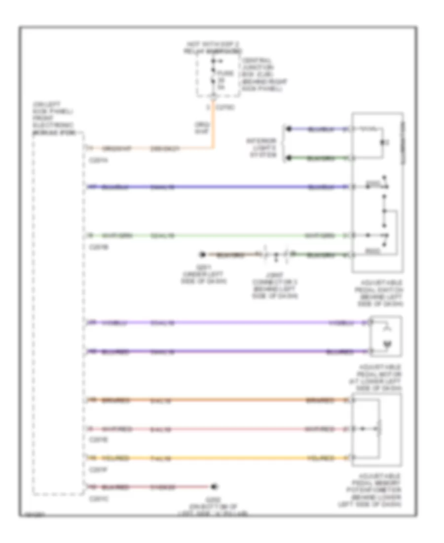
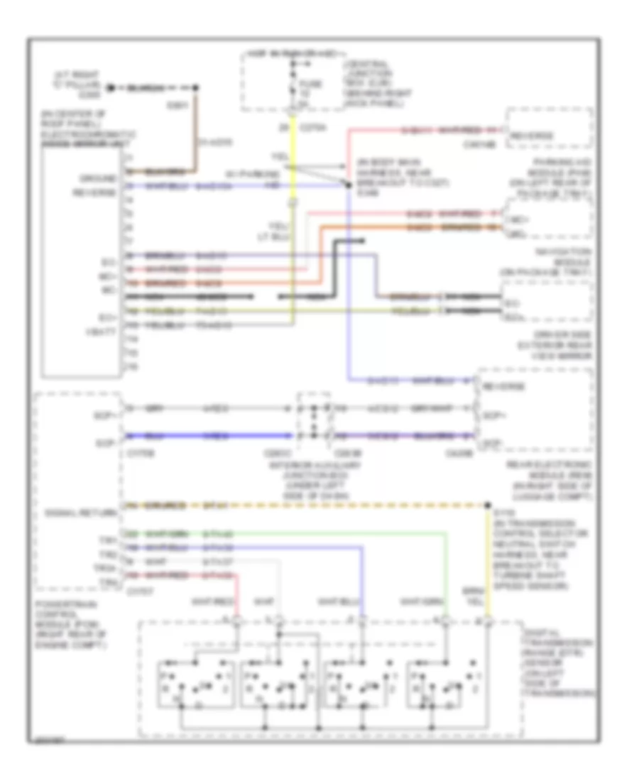
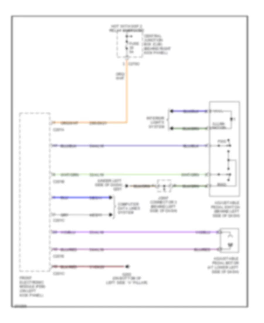
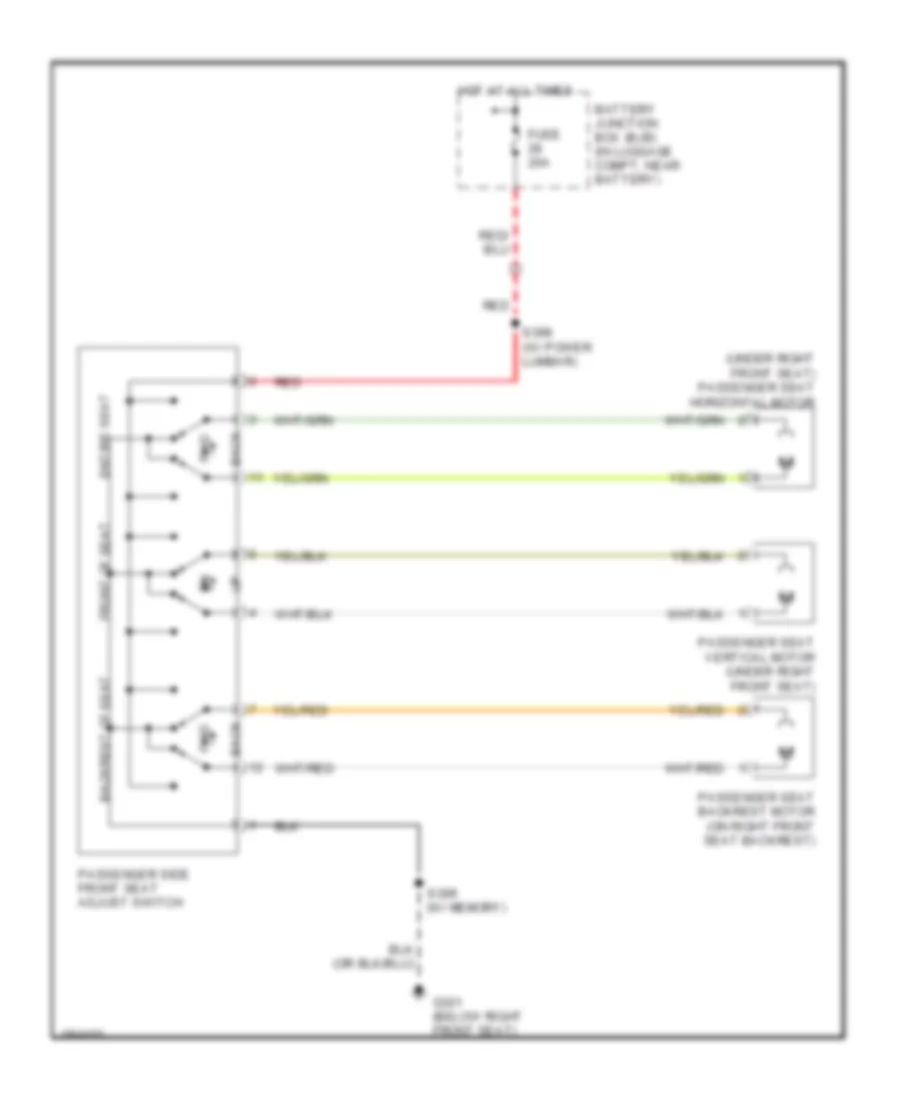
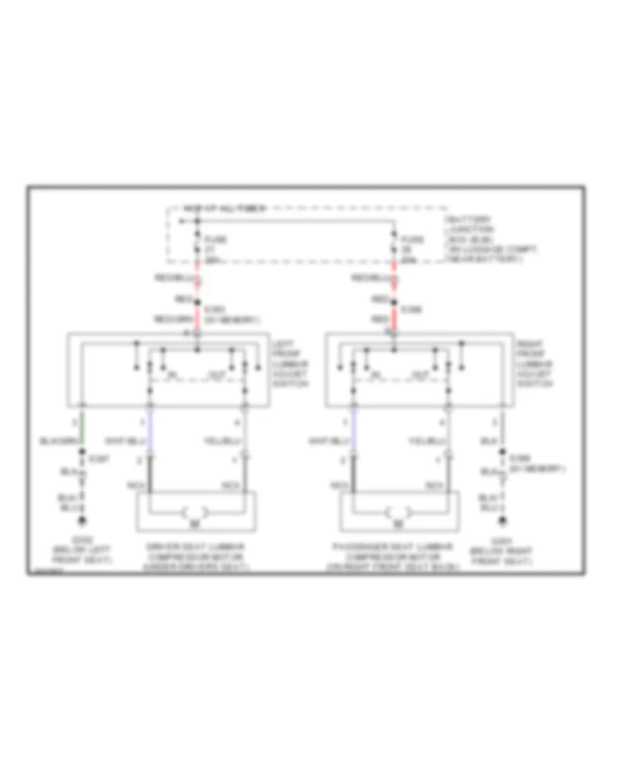
Adjustable Pedal Wiring Diagram for Lincoln LS 2005
List of elements for Adjustable Pedal Wiring Diagram for Lincoln LS 2005:
- (on left kick panel) front electronic module (fem)
- 29s-dk21
- 31-dk20
- 32-al19
- 34-al18
- 34-al19
- 35-al18
- 7-al18
- 8-al18
- 9-al18
- Adjustable pedal memory potentiometer (behind lower left side of dash)
- Adjustable pedal motor (at lower left side of dash)
- Adjustable pedal switch (behind left side of dash)
- C201a
- C201b
- C201c
- C201e
- C201f
- C270c
- Central junction box (cjb) (behind right kick panel)
- Fuse 5a
- Fwd
- G201 (under left side of dash)
- G202 (on bottom of left side ``a" pillar)
- Hot with ssp 2 relay energized
- Illumination
- Interior lights system
- Joint connector 3 (behind left side of dash)
- Rwd
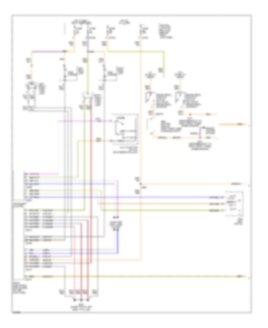
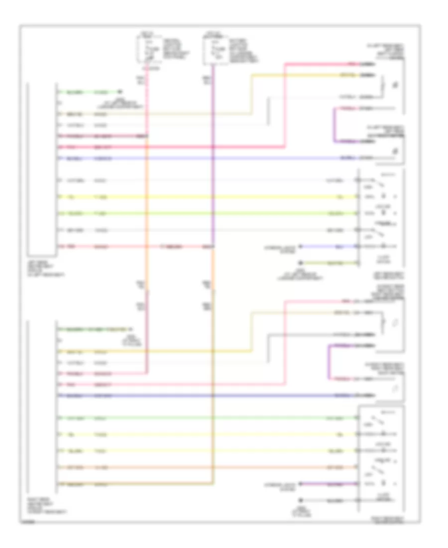
Memory Mirrors Wiring Diagram for Lincoln LS 2005
List of elements for Memory Mirrors Wiring Diagram for Lincoln LS 2005:
- 10-ad18
- 10-ad19
- 29-aj80
- 29s-aj86
- 29s-dk21
- 31-aj80b
- 31-dk20a
- 32-ad10
- 32-ad30
- 32-ad32
- 32-ad7
- 33-ad10
- 33-ad12
- 33-ad7
- 34-ad11
- 34-ad29
- 34-ad31
- 34-ad8
- 35-ad11
- 35-ad8
- 4-eg11
- 4-eg13
- 5-eg11
- 5-eg13
- 7-ad18
- 7-ad19
- 7s-ah27
- 8-ad18
- 8-ad19
- 8-ah27
- 8-ah31
- 8-ah32
- 9-ad18
- 9-ad19
- 91-aj80
- C201a
- C201c
- C201e
- C270c
- C270d
- C270e
- C501a
- C501c
- C501d
- Central junction box (cjb) (behind right kick panel)
- Computer data lines system
- Defogger system
- Direct- tional switch
- Driver door module (in driver's door)
- Driver side exterior rear view mirror
- Ec (+)
- Ec (-)
- Exterior rear view mirror switch
- Front electronic module (fem) (on left kick panel)
- Fuse 10a
- Fuse 5a
- G202 (on bottom of left side "a" pillar)
- G203 (behind lower left side of dash)
- Heated mirror
- Hot at all times
- Hot with ssp 1 relay energized
- Hot with ssp 2 relay energized
- Illum
- Interior lights system
- L/r sens
- Left/ right
- Left/right mirror select switch
- Memory set switch
- Mirrors system
- Nca
- On ind
- Passenger side exterior rear view mirror
- Puddle lamp
- S210
- S501
- Set
- U/d sens
- Up/ down
Memory Seat Wiring Diagram for Lincoln LS 2005
List of elements for Memory Seat Wiring Diagram for Lincoln LS 2005:
- (below left
- (in seat back control harness, near breakout to driver's seat rear height motor)
- (under driver's seat) driver seat horizontal motor
- 10-ah82
- 10-ah83
- 10-ah84
- 10-ah85
- 29-ah80
- 30-ah80
- 31-ah80
- 32-ah36
- 32-ah37
- 32-ah38
- 32-ah41
- 33-ah36
- 33-ah37
- 33-ah38
- 33-ah41
- 4-ah80
- 4-eg13
- 5-ah80
- 5-eg13
- 7-ah30
- 7-ah80
- 7s-ah27
- 8-ah24
- 8-ah25
- 8-ah26
- 8-ah27
- 8-ah30
- 8-ah31
- 8-ah32
- 8-ah82
- 8-ah83
- 8-ah84
- 8-ah85
- 9-ah30
- 9-ah80
- 91-ah80
- Battery junction box (bjb) (in luggage compt, near battery)
- C270d
- C341a
- C341b
- C341c
- C501a
- C501d
- Central junction box (cjb) (behind right kick panel)
- Computer data lines system
- Driver door module (in driver's door)
- Driver memory backrest sensor (in driver's seat)
- Driver memory seat front height sensor (under driver's seat)
- Driver memory seat horizontal sensor (under driver's seat)
- Driver memory seat rear height sensor (under driver's seat)
- Driver seat backrest motor (on driver's seat back)
- Driver seat front height motor (under driver's seat)
- Driver seat module (under driver's seat)
- Driver seat rear height motor (under driver's seat)
- Driver side front seat adjust switch
- Front seat) g302
- Front up/ down
- Fuse 20a
- Fuse 5a
- G203 (behind lower left side of dash)
- G302 (below left front seat)
- Hot at all times
- Interior lights system
- Memory set switch
- Rear up/ down
- Recline fwd/ rwd
- Red
- S210
- S313
- S393
- S394
- S395
- S396
- S397
- S501
- Seat fwd/ rwd
- Set
Steering Column Memory Wiring Diagram for Lincoln LS 2005
List of elements for Steering Column Memory Wiring Diagram for Lincoln LS 2005:
- 29-al12
- 31-al11
- 32-al6
- 33-al6
- 34-al7
- 35-al7
- 4-eg8
- 5-eg8
- 7-al17
- 8-al10
- 8-al16
- 8-al17
- 9-al10
- 9-al17
- C220a
- C220b
- C220c
- C270a
- Central junction box (cjb) (behind right kick panel)
- Computer data lines system
- Down
- Fuse 19 15a
- G201 (under left side of dash)
- Hot at all times
- Instrument cluster
- Out
- Steering column position motor (on steering column)
- Steering column position sensor (on steering column)
- Steering column position switch (on steering column)
- Telescope
- Tilt
NAVIGATION
Navigation Wiring Diagram for Lincoln LS 2005
List of elements for Navigation Wiring Diagram for Lincoln LS 2005:
- 1-gk18
- 10-gk24
- 10-gk25
- 10-gk26
- 10-gk8
- 2-gk18
- 30-gk8a
- 31-gk6
- 31-gk8
- 4-eg17
- 4-gk8
- 48-gk8
- 5-eg17
- 5-gk8
- 8-cf63
- 8-gk23
- 8-gk35
- 8-mc8
- 9-gk35a
- 9-mc8
- Abs control module (right front side of engine compartment)
- Acc pwr
- Audio shield
- Audio/navigation control unit (behind center of dash)
- Battery junction box (bjb) (in luggage compartment, near battery)
- C2253a
- C2253c
- C270a
- Can+
- Can-
- Central junction box (cjb) (behind right kick panel)
- Clock
- Computer data lines system
- Fuse 10a
- Fuse 20a
- Fuse 5a
- G g
- G201 (under left side of dash)
- G203 (behind lower left side of dash)
- G400 (at left rear of luggage compt)
- Ground
- Hot at all times
- Hot in start
- Mic+
- Mic-
- Mirrors system
- Navigation module (on package tray)
- Nca
- Power windows system
- Red
- Rtn
- S250
- S440 (in breakout to navigation module)
- Scp+
- Scp-
- Sync
- Vbatt
- Video shield
- Voice+
- Voice-
- Vpwr
- Vss
- W/ stability assist
- W/o stability assist
Parking Assistant Wiring Diagram for Lincoln LS 2005
List of elements for Parking Assistant Wiring Diagram for Lincoln LS 2005:
- (at left rear of luggage compartment) g400
- (in breakout to right parking aid ultrasonic sensor) s415
- (in rear parking aid sensor harness, in breakout to c405)
- (w/ stability assist)
- (w/o stability assist)
- 20-gn10
- 31s-gn21
- 4-gn10
- 7-gn1
- 7-gn21
- 7-gn23
- 8-gn11
- 8-gn12
- 8-gn14
- 8-gn19
- 8-gn20
- 8-gn21
- 9-gn1
- 91-gn10
- Abs control module (right front side of engine compartment)
- C270d
- C4014a
- C4014b
- Central junction box (cjb) (behind right kick panel)
- Computer data lines system
- Fuse 29 5a
- G300 (at right
- Ground
- Hot in run
- Interior lights system
- Left parking aid ultrasonic sensor (at center rear of luggage compartment)
- Left sig
- Mirrors system
- On ind
- Pam ind
- Parking aid disable switch
- Parking aid module (pam) (on left rear of package tray)
- Parking aid radar sensor (at center rear of luggage compartment)
- Radar sig
- Reverse
- Right parking aid ultrasonic sensor (at center rear of luggage compartment)
- Right sig
- S233
- S412
- S901
- Sig rtn
- Ubp
- Vpwr
- Vref
- Vss
- ``c" pillar)
POWER DISTRIBUTION
Power Distribution Wiring Diagram (1 of 5) for Lincoln LS 2005
List of elements for Power Distribution Wiring Diagram (1 of 5) for Lincoln LS 2005:
- (behind right kick panel) central junction box (cjb)
- (in dash panel to headlamp junction harness, near breakout to c110) s114
- (in dash panel to headlamp junction harness, near breakout to right front foglamp) s108
- (in dash panel to headlamp junction harness, near breakout to underhood auxiliary junction box) s155
- (in dash panel to headlamp junction harness, near breakout to underhood auxiliary junction box) s160
- (in luggage compartment, near battery) battery junction box (bjb)
- (not used)
- 60a
- Battery
- Battery junction box (bjb) (in luggage compartment, near battery)
- C1010a
- C1010c
- C197c
- C201a
- C201b
- C201f
- C270a
- C270b
- C270c
- C270d
- C270e
- C4066a
- C4066b red
- C420d
- C501a
- Driver door module
- Engine cooling fan motor
- Front electronic module (fem)
- Fuse 10a
- Fuse 15a
- Fuse 30a
- Fuse 40a
- Fuse 5a
- Generator
- In breakout to battery junction box) s429
- In-line fuse (at right kick panel)
- Junction block (on right front fender)
- Left front park/turn lamp
- Left headlamp
- Left high intensity discharge headlamp relay
- Mega fuse (in luggage compartment, 175a near battery junction box)
- Nca
- Passive anti-theft transceiver module
- Rear electronic module (rem)
- Rear window defrost relay
- Red
- Right front park/turn lamp
- Right headlamp
- Right high intensity discharge headlamp relay
- Ssp 1 relay
- Ssp 2 relay
- Starter motor
- To fuse 28 (diagram 2 of 5)
- To splice s112 (diagram 4 of 5)
- To ssp 3 relay (diagram 2 of 5)
- To ssp 4 relay (diagram 2 of 5)
- To stud junction box (diagram 4 of 5)
- W/ hid lamps
- W/o hid lamps
Power Distribution Wiring Diagram (2 of 5) for Lincoln LS 2005
List of elements for Power Distribution Wiring Diagram (2 of 5) for Lincoln LS 2005:
- (in body main harness, in breakout to battery junction box) s422
- (in body main harness, in breakout to fuel door release solenoid) s430
- (in body main harness, near breakout to c327) s312
- (in body main harness, near breakout to g301) s301
- (in luggage compartment, near battery) battery junction box (bjb)
- (in power seat harness, near breakout to passenger seat vertical motor) s398
- (in seat back control harness, near breakout to driver's seat module) s393
- Battery junction box (bjb) (in luggage compartment, near battery)
- C270a
- C270d
- C283a
- C283b
- C283d
- C3031a
- C3036a
- C341b
- C420c
- Central junction box (cjb) (behind right kick panel)
- Driver seat module
- Driver side climate controlled seat module
- Driver side exterior rear view mirror
- Driver side front power window motor
- Driver side front seat adjust switch
- Electronic hidden antenna module (eham)
- From a
- From s429 (diagram 1 of 5)
- Fuel door release solenoid
- Fuse 10a
- Fuse 15a
- Fuse 20a
- Fuse 30a
- Fuse 31 (diagram 1 of 5)
- Fuse 5a
- Glove box lamp
- High mounted stoplamp
- High mounted stoplamp capacitor
- Interior auxiliary junction box (ajb) (under left side of dash)
- Joint connector 1 (behind right side of dash)
- Left front footwell lamp
- Left front lumbar adjust switch
- Left front map reading lamp
- Left license plate lamp
- Left rear grab handle lamp
- Left rear lamp assembly
- Left rear turn lamp
- Left reversing lamp
- Left vanity mirror lamp
- Luggage compartment lamp
- Navigation module
- Nca
- Passenger side climate controlled seat module
- Passenger side exterior rear view mirror
- Passenger side front power window motor
- Passenger side front seat adjust switch
- Rear electronic module (rem)
- Red
- Right front footwell lamp
- Right front lumbar adjust switch
- Right front map reading lamp
- Right license plate lamp
- Right rear grab handle lamp
- Right rear lamp assembly
- Right rear turn lamp
- Right reversing lamp
- Right vanity mirror lamp
- Ssp 3 relay
- Ssp 4 relay
- To fuse 25 (diagram 3 of 5)
- W/ memory
- W/ power lumbar
- W/o memory
Power Distribution Wiring Diagram (3 of 5) for Lincoln LS 2005
List of elements for Power Distribution Wiring Diagram (3 of 5) for Lincoln LS 2005:
- (in body main harness, in breakout to c432) s432
- (in body main harness, near breakout to driver's side impact sensor 1) s302
- (in body main harness, near breakout to inertia fuel shutoff switch) s210
- (in dash panel to headlamp junction, near breakout to c291) s260
- (in luggage compartment, near battery) battery junction box (bjb)
- (in seat back control harness, near breakout to driver's seat module) s396
- (not used)
- (w/o navigation) (w/ navigation)
- Audio unit
- Audio/ navigation control unit
- Auto park brake release switch
- Autolamp/ sunload sensor
- Battery junction box (bjb) (in luggage compartment, near battery)
- Brake pedal position switch
- C102a
- C175b
- C201c
- C220a
- C220b
- C2253a
- C228a
- C270a
- C270c
- C270d
- C290b
- C341c
- C4208b
- C420d
- C420f
- C420g
- C466a
- C501a
- Center image amplifier
- Central junction box (cjb) (behind right kick panel)
- Console 1 power point (on center console)
- Console 2 power point (on center floor pan)
- Data link connector (dlc)
- Driver door module
- Driver seat module
- Driver side front seat adjust switch
- Electronic automatic temperature control (eatc) module
- Exterior rear view mirror switch
- From f fuse 21 (diagram 2 of 5)
- Front cigar lighter
- Front electronic module (fem)
- Fuel pump relay
- Fuse 10a
- Fuse 15a
- Fuse 20a
- Fuse 20a 30a
- Fuse 40a
- Fuse 5a
- G302 (below left front seat)
- Generator
- Instrument cluster
- Left rear heated seat module
- Off
- Powertrain control module (pcm)
- Radio amplifier
- Rear electronic module (rem)
- Red
- Right rear heated seat module
- Roof opening panel motor assembly
- Subwoofer amplifier
- To splice s213 (diagram 5 of 5)
- W/ navigation system
- W/ radio cdx6
- W/o navigation system
Power Distribution Wiring Diagram (4 of 5) for Lincoln LS 2005
List of elements for Power Distribution Wiring Diagram (4 of 5) for Lincoln LS 2005:
- (3.9l)
- (in dash panel to headlamp junction harness, near breakout to abs test connector) s122
- (in dash panel to headlamp junction harness, near breakout to underhood auxiliary junction box) s137
- (in dash panel to headlamp junction harness, near breakout to underhood auxiliary junction box) s139
- A/c clutch relay
- Abs control module
- Abs test connector
- Auxiliary coolant pump relay
- Blower motor relay
- C285a
- C285b
- C4205a
- Coolant control valve solenoid
- Cops & heated oxygen sensor (ho2s) relay
- Electronic park brake module
- Fog lamp relay
- From fuse 31 (diagram 1 of 5)
- From h fuse 14 (diagram 4 of 5)
- From mega fuse (diagram 1 of 5)
- Fuse 10a
- Fuse 15a
- Fuse 20a
- Fuse 30a
- Fuse 40a
- Heated wiper park relay
- Horn relay
- Pcm power relay
- Red
- Starter relay
- Stud junction box (at left kick panel, on interior auxiliary junction box)
- To fuse 1 (diagram 4 of 5)
- Underhood auxiliary junction box (ajb) (in right front of engine compartment)
- Windshield wiper motor
Power Distribution Wiring Diagram (5 of 5) for Lincoln LS 2005
List of elements for Power Distribution Wiring Diagram (5 of 5) for Lincoln LS 2005:
- (in body main harness, near breakout to c275) s233
- (in body main harness, near breakout to driver's safety belt retractor preten- sioner)
- (in body main harness, near breakout to g204) s306
- (in body main harness, near breakout to inertia fuel shut-off switch) s208
- (in dash panel to headlamp junction harness, near breakout to underhood auxiliary junction box) s138
- (in main harness, near breakout to g201) red
- (not used)
- Abs test connector
- Acc
- Audio unit
- Audio/ navigation control unit
- C201f
- C220a
- C220b
- C2253a
- C228a
- C270a
- C270b
- C270c
- C270d
- C270e
- C290b
- C3031a
- C3036a
- C310a
- C4014b
- Central junction box (cjb) (behind right kick panel)
- Cops & heated oxygen sensor (ho2s) relay
- Digital transmission ranger (dtr) sensor
- Driver side climate controlled seat module
- Electrochromatic inside mirror unit
- Electronic automatic temperature control (eatc) module
- From fuse 22 (diagram 3 of 5)
- Front electronic module (fem)
- Fuse 10a
- Fuse 5a
- Ignition switch
- Inertia fuel shutoff (ifs) switch
- Instrument cluster
- Key-in ignition switch
- Left rear heated seat module
- Lock
- Off
- Parking aid module (pam)
- Passenger side climate controlled seat module
- Pcm power diode
- Pcm power relay
- Red
- Restraints control module
- Right rear heated seat module
- Run
- S213
- Start
- Traction control switch
- Transmission shift selector
- Underhood auxiliary junction box (ajb) (in right front of engine compartment)
- W/ navigation system
- W/ parking aid
- W/o navigation system
- Windshield wiper motor
POWER DOOR LOCKS
Power Door Locks Wiring Diagram for Lincoln LS 2005
List of elements for Power Door Locks Wiring Diagram for Lincoln LS 2005:
- (in body main harness, near breakout to passenger side impact sensor 1)
- (in left front door) driver side front door lock unit
- 1/2
- 10-aa70
- 29s-aa70
- 29s-aj86
- 29s-dk31
- 3/4
- 31-aj80b
- 31s-aa78
- 31s-aa79
- 32-aa1
- 32-aa11
- 32-aa16
- 32-aa2
- 33-aa10
- 33-aa15
- 4-eg13
- 5-eg13
- 5/6
- 7-aa70
- 7/8
- 8-aa10
- 8-aa11
- 8-aa20
- 8-aa21
- 8-aa70
- 9-aa70
- 9/0
- Anti-theft system
- Battery junction box (bjb) (in luggage compt, near battery)
- C270e
- C420c
- C501a
- C501c
- C501d
- Central junction box (cjb) (behind right kick panel)
- Computer data lines system
- Door ajar
- Driver door module (in driver's door)
- Driver side door lock switch
- Fuse 10a
- Fuse 15a
- G203 (behind lower left side of dash)
- G204 (on bottom of right side "a" pillar)
- Hot with ssp 1 relay energized
- Hot with ssp 4 relay energized
- Illumination
- Interior lights system
- Key pad switch assembly
- Left rear door lock actuator (in left rear door)
- Lock
- Lock pos
- Passenger side door lock switch
- Passenger side front door lock unit (in right front door)
- Pwr
- Rear electronic module (rem) (in right side of luggage compt)
- Reset
- Right rear door lock actuator (in right rear door)
- S303
- S304
- S501
- S504
- S601
- Set
- Sig rtn
- Unlock
- Unlock pos
- Vref
POWER MIRRORS
Electronic Day/Night Mirror Wiring Diagram, with Navigation for Lincoln LS 2005
List of elements for Electronic Day/Night Mirror Wiring Diagram, with Navigation for Lincoln LS 2005:
- (at right "c" pillar) g300
- (in body main harness, near breakout to c327) s348
- (in center of roof panel) electrochromatic inside mirror unit
- 3/4
- 31-ad15
- 4-eg12
- 4-re8
- 48-mc8
- 5-eg12
- 5-re8
- 7-ad15
- 75-ad15
- 8-ad15
- 8-ad15a
- 8-gn11
- 8-mc8
- 8-ta37
- 8-ta38
- 8-ta39
- 8-ta40
- 9-ad15
- 9-mc8
- 9-ta1
- C175b
- C175t
- C270a
- C283b
- C283c
- C4014b
- C420b
- Central junction box (cjb) (behind right kick panel)
- Digital transmission range (dtr) sensor (on left side of transmission)
- Driver side exterior rear view mirror
- Ec+
- Ec-
- Fuse 5a
- Ground
- Hot in run or acc
- Interior auxiliary junction box (under left side of dash)
- Mc+
- Mc-
- Navigation module (on package tray)
- Nca
- Parking aid module (pam) (on left rear of package tray)
- Powertrain control module (pcm) (right rear of engine compt)
- Rear electronic module (rem) (in right side of luggage compt)
- Reverse
- S901
- Scp+
- Scp-
- Signal return
- Tr1
- Tr2
- Tr3a
- Tr4
- Vbatt
- W/ parking aid
Electronic Day/Night Mirror Wiring Diagram, without Navigation for Lincoln LS 2005
List of elements for Electronic Day/Night Mirror Wiring Diagram, without Navigation for Lincoln LS 2005:
- (at right "c" pillar) g300
- (in body main harness, near breakout to c327) s348
- (in center of roof panel) electrochromatic inside mirror unit
- 3/4
- 31-ad15
- 4-eg12
- 4-re8
- 5-eg12
- 5-re8
- 7-ad15
- 75-ad15
- 8-ad15
- 8-ad15a
- 8-gn11
- 8-ta37
- 8-ta38
- 8-ta39
- 8-ta40
- 9-ad15
- 9-ta1
- C175b
- C175t
- C270a
- C283b
- C283c
- C4014b
- C420b
- Central junction box (cjb) (behind right kick panel)
- Digital transmission range (dtr) sensor (on left side of transmission)
- Driver side exterior rear view mirror
- Ec+
- Ec-
- Fuse 5a
- Ground
- Hot in run or acc
- Interior auxiliary junction box (under left side of dash)
- Nca
- Parking aid module (pam) (on left rear of package tray)
- Powertrain control module (pcm) (right rear of engine compt)
- Rear electronic module (rem) (in right side of luggage compt)
- Reverse
- S110 (in transmission control selector neutral switch harness, near breakout to turbine shaft speed sensor)
- S901
- Scp+
- Scp-
- Signal return
- Tr1
- Tr2
- Tr3a
- Tr4
- Vbatt
- W/ parking aid
Power Mirrors Wiring Diagram for Lincoln LS 2005
List of elements for Power Mirrors Wiring Diagram for Lincoln LS 2005:
- (on bottom of left side "a" pillar) g202
- 29-aj80
- 29s-aj86
- 29s-dk21
- 31-aj80b
- 31-dk20a
- 32-ad10
- 32-ad30
- 32-ad32
- 32-ad7
- 33-ad10
- 33-ad12
- 33-ad7
- 34-ad11
- 34-ad29
- 34-ad31
- 34-ad8
- 35-ad11
- 35-ad8
- 4-eg11
- 4-eg13
- 5-eg11
- 5-eg13
- 91-aj80
- C201a
- C201c
- C201e
- C270c
- C270d
- C270e
- C501a
- C501c
- C501d
- Central junction box (cjb) (behind right kick panel)
- Computer data lines system
- Control
- Defogger system
- Down
- Driver door module (in driver's door)
- Driver side exterior rear view mirror
- Ec+
- Ec-
- Electronic day/night mirror circuit
- Exterior rear view mirror switch
- Front electronic module (fem) (on left kick panel)
- Fuse 10a
- Fuse 5a
- G203 (behind lower left side of dash)
- Ground
- Heater
- Hot at all times
- Hot w/ ssp 1 relay energized
- Hot w/ ssp 2 relay energized
- Illum
- Interior lights system
- L mir l/r
- L mir u/d
- L/r
- L/r control
- Left
- Mirror
- Nca
- Passenger side exterior rear view mirror
- Puddle lamp
- R mir l/r
- R mir u/d
- Right
- Right mirror
- S210
- S501
- Scp +
- Scp -
- Scp+
- Scp-
- U/d control
- Up/dn
- Vbatt
- Vpwr
POWER SEATS
Adjustable Pedal Wiring Diagram for Lincoln LS 2005
List of elements for Adjustable Pedal Wiring Diagram for Lincoln LS 2005:
- (under left side of dash) g201
- 29s-dk21
- 31-dk20
- 32-al19
- 34-al18
- 34-al19
- 35-al18
- 4-eg11
- 5-eg11
- Adjustable pedal motor (at lower left side of dash)
- Adjustable pedal switch (behind left side of dash)
- C201a
- C201b
- C201c
- C201e
- C270c
- Central junction box (cjb) (behind right kick panel)
- Computer data lines system
- Front electronic module (fem) (on left kick panel)
- Fuse 5a
- Fwd
- G202 (on bottom of left side ``a" pillar)
- Hot with ssp 2 relay energized
- Illumi- nation
- Interior lights system
- Joint connector 3 (behind left side of dash)
- Rwd
Driver Power Seat Wiring Diagram for Lincoln LS 2005
List of elements for Driver Power Seat Wiring Diagram for Lincoln LS 2005:
- Back
- Backrest of seat
- Battery junction box (bjb) (in luggage compt, near battery)
- Driver seat backrest motor (on driver's seat back)
- Driver seat front height motor (under driver's seat)
- Driver seat horizontal motor (under driver's seat)
- Driver seat rear height motor (under driver's seat)
- Driver side front seat adjust switch
- Entire of seat
- Front of seat
- Fuse 20a
- Fwd
- G302 (below left front seat)
- Hot at all times
- Rear of seat
- Red
Front Seat Heater Wiring Diagram for Lincoln LS 2005
List of elements for Front Seat Heater Wiring Diagram for Lincoln LS 2005:
- (below right front seat) g301
- (under driver's seat) driver side climate controlled seat cushion element
- (under driver's seat) driver side climate controlled seat fan
- (under right front seat) passenger side climate controlled seat cushion element
- (w/ memory) s399
- 10-fa18
- 20-hc21
- 20-hc22
- 20s-fa18
- 20s-hc16
- 20s-hc17
- 20s-hc19
- 20s-hc20
- 30-hc21
- 30-hc22
- 31-hc21
- 31-hc22
- 31-hc22d
- 31s-fa18
- 31s-hc16
- 31s-hc17
- 31s-hc19
- 31s-hc20
- 4-hc21
- 4-hc22
- 8-fa18
- 8-hc16
- 8-hc19
- 8-hc23
- 8-hc24
- 9-hc16
- 9-hc19
- 9-hc23
- 9-hc24
- Battery junction box (bjb) (in luggage compt, near battery)
- C270d
- C3031a
- C3031b
- C3036a
- C3036b
- Central junction box (cjb) (behind right kick panel)
- Computer data lines system
- Driver side climate controlled seat backrest element (in driver's seat back)
- Driver side climate controlled seat module (under driver's seat)
- Fuse 30a
- Fuse 5a
- G302 (below left front seat)
- Hot at all times
- Hot in run
- Nca
- Passenger side climate controlled seat backrest element (on right front seat backrest)
- Passenger side climate controlled seat fan (under right front seat)
- Passenger side climate controlled seat module (under right front seat)
- Pnk
- S301
- S306
- S397
Passenger Power Seat Wiring Diagram for Lincoln LS 2005
List of elements for Passenger Power Seat Wiring Diagram for Lincoln LS 2005:
- (under right front seat) passenger seat horizontal motor
- Back
- Backrest of seat
- Battery junction box (bjb) (in luggage compt, near battery)
- Entire seat
- Front of seat
- Fuse 20a
- Fwd
- G301 (below right front seat)
- Hot at all times
- Passenger seat backrest motor (on right front seat backrest)
- Passenger seat vertical motor (under right front seat)
- Passenger side front seat adjust switch
- Red
- S398 (w/ power lumbar)
- S399 (w/ memory)
Rear Heated Seats Wiring Diagram for Lincoln LS 2005
List of elements for Rear Heated Seats Wiring Diagram for Lincoln LS 2005:
- (in left rear seat) left rear seat back heater
- (in left rear seat) left rear seat cushion heater
- (in right rear seat bottom) right rear seat cushion heater
- (in right rear seat) right rear seat back heater
- 10-hc21
- 20-hc21d
- 20s-hc17
- 30-hc21
- 31-hc21
- 31s-hc16
- 7-hc21
- 7-hc22
- 8-hc21
- 8-hc23
- 9-hc23
- Battery junction box (bjb) (in luggage compartment, near battery)
- C270d
- Central junction box (cjb) (behind right kick panel)
- Fuse 20a
- Fuse 5a
- G300 (at right ``c" pillar)
- G400 (at left rear of luggage compartment)
- High
- High ind
- Hot at all times
- Hot in run
- Illumi-
- Interior lights system
- Left rear heated seat module (in left rear seat)
- Left rear seat heater switch
- Low
- Low ind
- Nation
- Nca
- Pnk
- Red
- Right rear heated seat module (in right rear seat)
- Right rear seat heater switch
- S302
- S306
Rear Lumbar Wiring Diagram for Lincoln LS 2005
List of elements for Rear Lumbar Wiring Diagram for Lincoln LS 2005:
- Battery junction box (bjb) (in luggage compt, near battery)
- Driver seat lumbar compressor motor (under driver's seat)
- Fuse 20a
- G301 (below right front seat)
- G302 (below left front seat)
- Hot at all times
- Left front lumbar adjust switch
- Nca
- Out
- Passenger seat lumbar compressor motor (on right front seat back)
- Red
- Right front lumbar adjust switch
- S393 (w/ memory)
- S397
- S398
- S399 (w/ memory)
POWER TOP/SUNROOF
Power Top/Sunroof Wiring Diagram for Lincoln LS 2005
List of elements for Power Top/Sunroof Wiring Diagram for Lincoln LS 2005:
- (in breakout to driver's door module) s505
- Auto open
- Battery junction box (bjb) (in luggage compt, near battery)
- C501d
- Close
- Delayed acc pwr
- Driver door module (in driver's door)
- Fuse 20a
- G300 (at right "c" pillar)
- Global open/ close
- Hot at all times
- Open
- Power windows system
- Roof opening panel motor assembly (on center of roof, above headliner)
- Roof opening panel switch
- S237 (near breakout to c275)
- S238 (near breakout to c275)
- S502 (near breakout to c562)
- Slide switch
- Test circuit
- Tilt
POWER WINDOWS
Power Windows Wiring Diagram for Lincoln LS 2005
List of elements for Power Windows Wiring Diagram for Lincoln LS 2005:
- (behind center
- (behind lower left side of dash) g203
- (in body main harness, in breakout to battery junction box)
- (in body main harness, near breakout to c237)
- (in body main harness, near breakout to c291)
- (in driver's door trim harness, in breakout to
- (in driver's door trim harness, near breakout to c562)
- 10-aj14
- 10-aj24
- 10-aj43
- 10-gk8
- 30-dk30
- 30-dk30a
- 31-dk30a
- 31-dk30b
- 34-aj13
- 34-aj23
- 35-aj13
- 35-aj23
- 7-aj1
- 7-aj7
- 7s-aj20
- 7s-aj49
- 7s-aj50
- 7s-aj51
- 7s-aj52
- 8-aj14
- 8-aj24
- 8-aj43
- Acc pwr
- Audio/navigation
- Battery junction box (bjb) (in luggage compartment, near battery)
- Breakout to c275) harness, near (in body main s237
- C2253a
- C420b
- C420c
- C420d
- C420f
- C420g
- C504a
- C504b
- C5o1d
- Control unit
- Down
- Driver
- Driver door module (in driver's door)
- Driver side front power window motor (in left front door)
- Driver's door module)
- Fuse 20a
- Fuse 30a
- G203 (behind lower left side of dash)
- G204 (on bottom of right side ``a" pillar)
- G401 (at right rear of luggage compartment)
- Hot at all times
- Illumination
- Interior lights system
- Left rear
- Left rear power window motor (in left rear door)
- Left rear window adjust switch
- Lock
- Master window adjust switch
- Mlrmu
- Mlrwd
- Mrrwd
- Mrrwu
- Navigation module (on package tray)
- Of dash)
- One- touch dn
- One- touch down
- One- touch up
- Open/close
- Passenger
- Passenger side front power window motor (in right front door)
- Passenger side window adjust switch
- Rear electronic module (rem) (in right side of luggage compartment)
- Red
- Rest
- Right rear
- Right rear power window motor (in right rear door)
- Right rear window adjust switch
- Roof opening panel motor assembly (on center of roof, above headliner)
- S202
- S205 (in body main harness, near breakout to c237)
- S207
- S238 (in body main harness, near breakout to c275)
- S409
- S501
- S502
- S505
- S601
- Vbatt
RADIO
Base Radio Wiring Diagram for Lincoln LS 2005
List of elements for Base Radio Wiring Diagram for Lincoln LS 2005:
- (in main harness, near breakout to glove box lamp) s226
- (not used)
- 10-md10
- 10-md11
- 10-md17
- 10-md18
- 29-md15
- 29s-md7
- 31-md15
- 31s-md26
- 31s-pg24
- 4-ea8
- 4-eg10
- 5-ea8
- 5-eg10
- 50-md15
- 75-md15
- 8-md10
- 8-md11
- 8-md17
- 8-md18
- 8-md26
- Acp a
- Acp b
- Antenna
- Audio unit (behind center of dash)
- Battery junction box (bjb) (in luggage compartment, near battery)
- C175b
- C218b
- C270a
- C270d
- C283a
- C283b
- C290a
- C290b
- C290c
- Central junction box (cjb) (behind right kick panel)
- Computer data lines system
- Cruise control system
- Electronic hidden antenna module (eham) (on rear center of roof)
- Fuse 10a
- Fuse 20a
- Fuse 5a
- G201 (under left side of dash)
- Ground
- Hot at all times
- Hot in run or acc
- Hot in start
- Hot with ssp 3 relay energized
- Illumination
- Interior auxiliary junction box (ajb) (under left side of dash)
- Interior lights system
- L front spkr (+)
- L front spkr (-)
- L rear spkr (+)
- L rear spkr (-)
- Left front speaker
- Left rear speaker
- Media
- Mem dn
- Mem up
- Mute
- Nca
- Powertrain control module (pcm) (right rear of engine compartment)
- R front spkr (+)
- R front spkr (-)
- R rear spkr (+)
- R rear spkr (-)
- Right front speaker
- Right rear speaker
- S312
- Scp (+)
- Scp (-)
- Sig rtn
- Steering wheel assembly
- Steering wheel auxiliary audio controls
- Vbatt
- Volume dn
- Volume up
- Vpwr
- Vref
Premium Sound Radio Wiring Diagram, with Navigation (1 of 2) for Lincoln LS 2005
List of elements for Premium Sound Radio Wiring Diagram, with Navigation (1 of 2) for Lincoln LS 2005:
- (not used)
- 1-gk18
- 1-md19
- 10-gk24
- 10-gk25
- 10-gk26
- 10-md10a
- 10-md11a
- 10-md15
- 10-md17a
- 10-md18a
- 2-gk18
- 2-md19
- 29-md15
- 31-lk34
- 31-md15
- 31-md15a
- 31-md15b
- 31s-md26
- 4-ea8
- 4-gk8
- 48-gk6a
- 5-ea8
- 5-gk8
- 50-md15
- 64s-lk34
- 7-md27
- 8-gk23
- 8-gk35
- 8-md10a
- 8-md11a
- 8-md17a
- 8-md18a
- 8-md26
- 9-gk35
- Acc power
- Acp (+)
- Acp (-)
- Antenna
- Audio/navigation control unit (behind center of dash)
- Battery junction box (bjb) (in luggage compartment, near battery)
- C175b
- C2253a
- C2253b
- C2253c
- C2253d
- C270a
- Can (+)
- Can (-)
- Central junction box (cjb) (behind right kick panel)
- Clock
- Enable
- Fuse 20a
- Fuse 30a
- Fuse 5a
- G201 (under left side of dash)
- Ground
- Hot at all times
- Hot in start
- Illum feed
- Interior lights system
- L front spkr (+)
- L front spkr (-)
- L rear spkr (+)
- L rear spkr (-)
- Navigation system
- Nca
- Power windows system
- Powertrain control module (pcm) (right rear of engine compt)
- R front spkr (+)
- R front spkr (-)
- R rear spkr (+)
- R rear spkr (-)
- Red
- Rtn
- S200
- S226 (in main harness, near breakout to glove box lamp)
- Shield
- Sig rtn
- Subwoofer (+)
- Subwoofer (-)
- Sync
- Vbatt
- Video b
- Video g
- Video r
- Voice (+)
- Voice (-)
- Vpwr
- Vref
Premium Sound Radio Wiring Diagram, with Navigation (2 of 2) for Lincoln LS 2005
List of elements for Premium Sound Radio Wiring Diagram, with Navigation (2 of 2) for Lincoln LS 2005:
- C218b
- C4208a
- C4208b
- C466a
- C466b
- Cruise control system
- Enable
- G400 (at left rear of luggage compt)
- Ground
- Illumination
- Interior lights system
- L front spkr (+)
- L front spkr (-)
- L rear spkr (+)
- L rear spkr (-)
- Left (+)
- Left (-)
- Left front speaker
- Left rear speaker
- Left subwoofer
- Media
- Mem dn
- Mem up
- Mute
- Nca
- R front spkr (+)
- R front spkr (-)
- R rear spkr (+)
- R rear spkr (-)
- Radio amplifier (at left side of luggage compartment)
- Right (+)
- Right (-)
- Right front speaker
- Right rear speaker
- Right subwoofer
- S432 (in body main harness, in breakout to c432)
- Shield
- Steering wheel assembly
- Steering wheel auxiliary audio controls
- Subwoofer (+)
- Subwoofer (-)
- Subwoofer amplifier (on package tray)
- Vbatt
- Vol dn
- Vol up
Premium Sound Radio Wiring Diagram, without Navigation (1 of 2) for Lincoln LS 2005
List of elements for Premium Sound Radio Wiring Diagram, without Navigation (1 of 2) for Lincoln LS 2005:
- (not used)
- (on rear center of roof) electronic hidden antenna module (eham)
- (under left side of dash) g201
- 1-md12
- 1-md19
- 10-md10
- 10-md11
- 10-md17
- 10-md18
- 2-md12
- 2-md19
- 29-md15
- 29s-md7
- 31-md15a
- 31s-md26
- 4-ea8
- 4-eg10
- 48-md12
- 48-md15c
- 5-ea8
- 5-eg10
- 50-md15
- 7-md12
- 7-md19
- 75-md15
- 8-md10
- 8-md11
- 8-md17
- 8-md18
- 8-md26
- Acp a
- Acp b
- Amplifier (+)
- Amplifier (-)
- Antenna
- Audio unit (behind center of dash)
- Battery junction box (bjb) (in luggage compartment, near battery)
- C270a
- C270d
- C283a
- C283b
- C290a
- C290b
- C290c
- C290d
- Center image amplifier (behind front center of dash)
- Central junction box (cjb) (behind right kick panel)
- Computer data lines system
- Enable
- Fuse 10a
- Fuse 20a
- Fuse 5a
- G201 (under left side of dash)
- Gnd
- Ground
- Hot at all times
- Hot in run or acc
- Hot in start
- Hot with ssp 3 relay energized
- Interior auxiliary junction box (ajb) (under left side of dash)
- L front spkr (+)
- L front spkr (-)
- L rear spkr (+)
- L rear spkr (-)
- Left center image speaker
- Nca
- R front spkr (+)
- R front spkr (-)
- R rear spkr (+)
- R rear spkr (-)
- Right center image speaker
- S230
- S312
- Scp (+)
- Scp (-)
- Shield
- Sig rtn
- Subwoofer (+)
- Subwoofer (-)
- Vbatt
- Vpwr
- Vref
Premium Sound Radio Wiring Diagram, without Navigation (2 of 2) for Lincoln LS 2005
List of elements for Premium Sound Radio Wiring Diagram, without Navigation (2 of 2) for Lincoln LS 2005:
- (at left rear of
- 31s-pg24
- Battery junction box (bjb) (in luggage compartment, near battery)
- C175b
- C218b
- C466a
- C466b
- Cruise control system
- Enable
- Fuse 20a
- G400
- Gnd
- Hot at all times
- Illum
- Interior lights system
- Left front speaker
- Left rear speaker
- Left subwoofer
- Luggage compt)
- Media
- Mem
- Mute
- Nca
- Powertrain control module (pcm) (right rear of engine compt)
- Right front speaker
- Right rear speaker
- Right subwoofer
- S226 (in main harness, near breakout to glove box lamp)
- Shield
- Sig rtn
- Steering wheel assembly
- Steering wheel auxiliary audio controls
- Subwoofer amplifier (on package tray)
- Vbatt
- Volume dn
- Volume up
SHIFT INTERLOCK
Park Brake Release Wiring Diagram for Lincoln LS 2005
List of elements for Park Brake Release Wiring Diagram for Lincoln LS 2005:
- (below left front seat) g302
- (in breakout to electronic park brake motor)
- 10-cg15
- 30-cg16
- 31-cg16
- 31s-cg14
- 32-cg19
- 33-cg19
- 4-cg16
- 5-cg16
- 7-cg20
- 8-cg15
- 8-cg20
- 9-cg20a
- Auto park brake release switch (on center console)
- Auxiliary junction box (ajb) (underhood) (in right front of engine compartment)
- C270d
- C4205a
- C4205b
- Central junction box (cjb) (behind right kick panel)
- Computer
- Data lines system
- Electronic park brake module (at left side of luggage compartment)
- Electronic park brake motor (at left side of luggage compartment)
- Fuse 30a
- Fuse 5a
- G400 (at left rear of luggage compartment)
- Ground
- Hall sensor
- Hot at all times
- Illumination
- Interior lights system
- Joint conne- tor 5 (at left side of luggage compt)
- On ind
- Pwr
- Release
- S210
- S450 (in breakout to electronic park brake motor)
- S455
- Scp+
- Scp-
- Sig rtn
- Vbatt
Shift Interlock Wiring Diagram, with IVD for Lincoln LS 2005
List of elements for Shift Interlock Wiring Diagram, with IVD for Lincoln LS 2005:
- 29s-cf1
- Abs control module (right front side of engine compt)
- Auxiliary junction box (ajb) (interior) (under left side of dash)
- Bpp
- Brake pedal position switch (on top of brake pedal support)
- Brake shift interlock (behind left side of dash, near steering column)
- C175b
- C201c
- C201f
- C270d
- C283c
- C420b
- Central junction box (cjb) (behind right kick panel)
- Front electronic module (fem) (on left kick panel)
- Fuse 35 5a
- G201 (under left side of dash)
- Hot at all times
- Powertrain control (pcm) module (right rear of engine compt)
- Pwr
- Rear electronic module (rem) (in right side of luggage compt)
- Scp+
- Scp-
- Status
Shift Interlock Wiring Diagram, without IVD for Lincoln LS 2005
List of elements for Shift Interlock Wiring Diagram, without IVD for Lincoln LS 2005:
- (near breakout to right front wheel speed sensor) s101
- 29s-re13 c175b
- Abs control module (right front side of engine compt)
- Auxiliary junction box (ajb) (interior) (under left side of dash)
- Brake pedal position switch (on top of brake pedal support)
- Brake shift interlock (behind left side of dash, near steering column)
- C175b
- C201c
- C201f
- C270d
- C283c
- C420b
- Central junction box (cjb) (behind right kick panel)
- Front electronic module (fem) (on left kick panel)
- Fuse 35 5a
- G201 (under left side of dash)
- Hot at all times
- Powertrain control module (pcm) (right rear of engine compt)
- Pwr
- Rear electronic module (rem) (in right side of luggage compt)
- Scp+
- Scp-
STARTING/CHARGING
Charging Wiring Diagram for Lincoln LS 2005
List of elements for Charging Wiring Diagram for Lincoln LS 2005:
- 10-ba25
- 4-re8
- 5-re8
- 8-ba25
- Auxiliary junction box (ajb) (interior) (under left side of dash)
- Battery
- Battery junction box (bjb) (in luggage compartment, near battery)
- C175b
- C175e
- C220a
- C220b
- C270a
- C283c
- C283d
- Central junction box (cjb) (behind right kick panel)
- Fuse 10a
- Fuse 5a
- G201 (under left side of dash)
- G402 (at right side of luggage compt)
- Gen com
- Gen mon
- Generator
- Gnd
- Hot at all times
- Hot in run or acc
- Instrument cluster
- Joint connector 4 (behind left side of dash)
- Junction block (on right front fender)
- Power distribution system
- Powertrain control module (pcm) (right rear of engine compt)
- Red
- Scp+
- Scp-
- Starter motor
- Vbatt
- Vpwr
Starting Wiring Diagram for Lincoln LS 2005
List of elements for Starting Wiring Diagram for Lincoln LS 2005:
- 3/4
- Acc
- Auxiliary junction box (ajb) (underhood) (in right front of engine compartment)
- Auxiliary junction box (ajb) (underhood) (in right front of engine compt)
- Battery
- C220b
- C270a
- C270b
- Central junction box (cjb) (behind right kick panel)
- Charging circuit
- Digital transmission range (dtr) sensor (on left side of transmission)
- Fuse 30a
- Fuse 5a
- G104 (on right front fender)
- G402 (at right side of luggage compt)
- Hot at all times
- Ignition switch
- Instrument cluster
- Junction block (on right front fender)
- Lock
- Off
- Power distribution system
- Red
- Run
- Start
- Starter motor
- Starter relay
SUPPLEMENTAL RESTRAINTS
Supplemental Restraints Wiring Diagram (1 of 2) for Lincoln LS 2005
List of elements for Supplemental Restraints Wiring Diagram (1 of 2) for Lincoln LS 2005:
- (below left front seat) g302
- (below right front seat) g301
- (on driver's seat backrest) driver side thorax air bag module
- (on driver's seat backrest) left side air bag module
- 15-ja10
- 30s-ja11
- 30s-ja32
- 30s-ja33
- 30s-ja34
- 30s-ja37
- 30s-ja38
- 30s-ja48
- 30s-ja50
- 30s-ja51
- 30s-ja8
- 31-ja10
- 31-ja10a
- 31s-ja11
- 31s-ja14b
- 31s-ja32
- 31s-ja33
- 31s-ja34
- 31s-ja37
- 31s-ja38
- 31s-ja48
- 31s-ja50
- 31s-ja51
- 31s-ja8
- 4-ee10
- 7-ja39
- 7-ja40
- 7-ja41
- 7-ja43
- 7-ja49
- 7-ja53
- 8-ge52
- 8-ja54
- 8-ja55
- 8-rj10
- 9-ja39
- 9-ja40
- 9-ja41
- 9-ja43
- 9-ja49
- 9-ja53
- Air bag feed 1
- Air bag feed 2
- C218a
- C270d
- C310a
- C310b
- Central junction box (cjb) (behind right kick panel)
- Chime
- Deploy
- Driver 1 side impact sensor (on left side of floor, near "b" pillar)
- Driver air bag unit (at center of steering wheel)
- Driver safety belt buckle switch (in seat belt buckle)
- Driver safety belt retractor pretensioner (at base of left "b" pillar, behind trim)
- Fuse 10a
- Ground
- Hot in run or start
- Iso
- Nca
- Passenger 1 side impact sensor (on right side of floor, near "b" pillar)
- Passenger safety belt buckle switch (in seat belt buckle)
- Passenger safety belt retractor pretensioner (at base of right "b" pillar, behind trim)
- Pin shorting bars engaged when module connector is disconnected from harness (shorting bars are connected between pins: 1-2, 3-4, 5-6 & 13-14 conn. c310a) 1-2 & 3-4, 5-6 & 21-22 conn. c310b)
- Restraints control module (on center floor pan)
- Shorting bar
- Sig rtn
- Signal
- Signal return
- Signal rtn
- Stage
- Steering wheel assembly
- Vpwr
- Vref
- W/ thorax air bag
- W/o thorax air bag
- Warning ind
Supplemental Restraints Wiring Diagram (2 of 2) for Lincoln LS 2005
List of elements for Supplemental Restraints Wiring Diagram (2 of 2) for Lincoln LS 2005:
- (behind left side of dash) left side air bag curtain bridge resistor
- (behind left side of dash) right side air bag curtain bridge resistor
- (not used)
- (on left "a" pillar) driver side air curtain module
- (on right "a" pillar) passenger side air curtain module
- (under left side of dash) g201
- 8-rj10
- Air bag ind
- C175b
- C220a
- Chime
- Data link connector (dlc) (under left side of dash)
- Driver seat track position sensor (under driver's seat)
- Front impact severity sensor (at right front of engine compt)
- Instrument cluster
- Left rear side impact sensor (on left rear of vehicle floor)
- Passenger air bag module (at lower right side of dash)
- Passenger side thorax air bag module (on right front seat backrest)
- Powertrain control module (pcm) (right rear of engine compartment)
- Right rear side impact sensor (on right rear of floor)
- Right side air bag module (on right front seat backrest)
- Shorting bar
- Signal
- Stage 1
- Stage 2
- W/ thorax air bag
- W/o thorax air bag
TRANSMISSION
A/T Wiring Diagram for Lincoln LS 2005
List of elements for A/T Wiring Diagram for Lincoln LS 2005:
- (3.0l: in breakout to inlet manifold runner control solenoid 1) (3.9l: in breakout to ignition transformer capacitor 1)
- (in right front of engine compt) auxiliary junction box (underhood)
- (near breakout to
- (near breakout to ambient air temp sensor) s113
- (near breakout to c291) s220
- (near breakout to right front fog lamp) s105
- (near breakout to underhood auxiliary junction box)
- (near breakout to yaw velocity sensor)
- (on top of brake pedal support)
- (under left side of dash)
- (under left side of dash) auxiliary junction box (interior)
- 15s-re21
- 15s-re8
- 29-re8
- 29s-cf2
- 29s-re13
- 3/4
- 31-re21
- 31-re25
- 31-re26
- 31-re8
- 4-ec7
- 4-re8
- 5-ec7
- 5-re8
- 7-re14
- 7-rj28
- 8-rj28
- 8-rj33
- 8-rj39
- 8-ta21
- 8-ta26
- 8-ta27
- 8-ta34
- 8-ta37
- 8-ta38
- 8-ta39
- 8-ta40
- 8-ta51
- 8-ta67
- 8-ta68
- 8-ta74
- 9-re1
- 9-re8
- 9-rj28
- 9-ta1
- 91-re27
- 91s-ta23
- 91s-ta24
- 91s-ta47
- 91s-ta63
- 91s-ta64
- 91s-ta65
- 91s-ta69
- 91s-ta70
- Abs control module (right front side of engine compt)
- Automatic transmission
- Auxiliary junction box (underhood) (in right front of engine compt)
- Battery junction box (in luggage compt, near battery)
- Brake in
- Brake pedal position switch
- C175b
- C175e
- C175t
- C220b
- C270b
- C270c
- C270d
- C283c
- C283d
- Can +
- Can -
- Central junction box (cjb) (behind right kick c270d
- Cyl temp
- Cylinder head temperature sensor (3.0l: middle of left cyl head) (3.9l: on left cyl head)
- Data link connector
- Dc volt
- Digital transmission range (dtr) sensor (left side of transmission)
- Driver's safety belt retractor pretensioner)
- Engine controls system
- Engine controls system (near breakout to turbine shaft speed sensor) s110
- Fuse 15a
- Fuse 30a
- Fuse 5a
- G101 (on right radiator support)
- G102 (on right front fender)
- G302 (below left front seat)
- Ground
- Hot at all times
- Hot in run
- Hot in run or start
- Illum- ination
- Instrument cluster
- Interior lights system
- Intermediate shaft speed (iss) sensor (on left side of trans)
- Iss
- Joint connector 4 (behind left side of dash)
- Manual mode switch +
- Manual mode switch -
- Mt sw +
- Mt sw -
- Od off
- Oss
- Output shaft speed sensor (on left side of trans)
- Panel)
- Park sense switch
- Pcm power diode
- Pcm power relay
- Pcs a
- Pcs b
- Pcs c
- Power
- Powertrain control module (pcm) (right rear of engine compt)
- Pressure control solenoids
- Prg sig
- Red
- Return
- S101
- S102 (near breakout to right front wheel speed sensor)
- S112
- S126
- S138
- S208 (in body main harness, near breakout to inertia fuel shut-off switch)
- S328
- Scp +
- Scp -
- Shift solenoids
- Sig rtn
- Signal rtn
- Ss a
- Ss b
- Ss c
- Ss d
- Tcc sol
- Tft
- Throttle position sensor (3.0l: on right side of engine) (3.9l: on top front of engine)
- Torque converter clutch solenoid
- Tps
- Tps rtn
- Tps sig
- Tr1
- Tr2
- Tr3a
- Tr4
- Transmission control switch
- Transmission fluid temperature sensor
- Transmission shift selector (on center of floor pan)
- Tss
- Turbine shaft speed (tss) sensor (on left side of trans)
- W/ stability assist
- W/o stability assist
TRUNK, TAILGATE, FUEL DOOR
Fuel Door Release Wiring Diagram for Lincoln LS 2005
List of elements for Fuel Door Release Wiring Diagram for Lincoln LS 2005:
- Battery junction box (bjb) (in luggage compt, near battery)
- Fuel door release solenoid (on right side of luggage compartment)
- Fuel door release switch
- Fuse 10a
- G201 (under left side of dash)
- Hot w/ ssp 4 relay energized
- Interior lights system
- S430
Trunk Release Wiring Diagram for Lincoln LS 2005
List of elements for Trunk Release Wiring Diagram for Lincoln LS 2005:
- (in right side of luggage compartment) rear electronic module (rem)
- (on left kick panel) front electronic module (fem)
- 10a
- 15a
- Battery junction box (bjb) (in luggage compt, near battery)
- C201c
- C201e
- C270c
- C420b
- C420c
- Central junction box (cjb) (behind right kick panel)
- Computer data lines system
- Fuse 1
- Fuse 20
- G201 (under left side of dash)
- G401 (at right rear of luggage compt)
- Hot at all times
- Hot w/ ssp4 relay energized
- Joint connector 3 (behind left side of dash)
- Luggage compartment lid release solenoid (in luggage compt deck lid)
- Luggage compartment lid release switch
- Pwr
- S260
- Scp+
- Scp-
- Vbatt
- Vref
WARNING SYSTEMS
Warning Systems Wiring Diagram for Lincoln LS 2005
List of elements for Warning Systems Wiring Diagram for Lincoln LS 2005:
- (in seat belt buckle) passenger safety belt buckle switch
- (on right radiator support) g101
- (under left side of dash) g201
- 10-le21
- 10-le47
- 15-gg14
- 15-ja148
- 29-al12
- 29-dk20
- 29-dk31
- 29-gg11
- 29s-dk22
- 30s-gm7
- 31-al11
- 31-dk20a
- 31-dk30h
- 31a-ja14
- 31s-gl12
- 31s-gl19
- 31s-gl46
- 31s-gl47
- 31s-ja14
- 4-eg11
- 4-eg12
- 4-eg8
- 4-re8
- 5-eg11
- 5-eg12
- 5-eg8
- 5-re8
- 75-gg15
- 8-gc21
- 8-gc8
- 8-ge52
- 8-gl20
- 8-ja54
- 8-ja55
- 8-le21
- 8-lf14
- 9-le29
- 91-gg11
- 91s-gl13
- Auto on
- C175b
- C201a
- C201b
- C201c
- C201e
- C201f
- C220a
- C220b
- C220c
- C270a
- C270c
- C270d
- C283c
- C283d
- C310a
- C310b
- C420b
- C420c
- C420d
- Central junction box (cjb) (behind right kick panel)
- Computer data lines system
- Driver safety belt buckle switch (in seat belt buckle)
- Driver side front door lock unit (in left front door)
- Front electronic module (fem) (on left kick panel)
- Fuse 10a
- Fuse 15a
- Fuse 5a
- G202 (on bottom of left side "a" pillar)
- G203 (behind lower left side of dash)
- G204 (on bottom of right side "a" pillar)
- G300 (at right "c" pillar)
- G301 (below right front seat)
- G302 (below left front seat)
- G400 (at left rear of luggage compartment)
- G401 (at right rear of luggage compartment)
- Hot at all times
- Hot in run or acc
- Hot in start or run
- Hot with ssp 2 relay energized
- Ignition switch
- Instrument cluster
- Interior auxiliary junction box (ajb) (under left side of dash)
- Joint connector 4 (behind left side of dash)
- Key in
- Left rear door lock actuator (in left rear door)
- Low beam
- Luggage compartment lid ajar switch (in decklid)
- Main light switch
- Off
- Oil pressure switch (3.0l: on lower left side of engine) (3.9l: on lower front of engine)
- Park
- Passenger side front door lock unit (in right front door)
- Powertrain control module (pcm) (right rear of engine compt)
- Rear electronic module (rem) (in right side of luggage compt)
- Restraints control module (on center floor pan)
- Right rear door lock actuator (in right rear door)
- S260
- S504
- Scp (+)
- Scp (-)
- Washer fluid level switch (at right front of engine compt)
WIPER/WASHER
Wiper/Washer Wiring Diagram for Lincoln LS 2005
List of elements for Wiper/Washer Wiring Diagram for Lincoln LS 2005:
- (at right front of engine compt) washer fluid level switch
- (near left shock tower) windshield wiper motor
- (not used)
- (on right radiator support) g101
- (under left side of dash) g201
- 0. off 1. high 2. low
- 29-dk20
- 4-eg11
- 5-eg11
- 7. mist 21. interval 1 22. interval 2 23. interval 3 24. interval 4 25. interval 5
- 8-gc8
- 8-ka5
- Auxiliary junction box (ajb) (underhood) (in right front of engine compt)
- C201c
- C201f
- C210b
- C270c
- C270e
- Central junction box (cjb) (behind right kick panel)
- Computer data lines system
- Front electronic module (fem) (on left kick panel)
- Fuse 20 10a
- Fuse 20 30a
- Fuse 26 5a
- G100 (on left radiator support)
- Hot at all times
- Hot in run or acc
- Joint connector 3 (behind left side of dash)
- Microprocessor
- Multi-function switch (on steering column)
- Rest
- Run
- S260
- Scp+
- Vbatt
- Vref
- Wash switch
- Windshield washer pump motor (at right side of engine compt)
- Windshield washer relay
- Wiper high/low relay
- Wiper on
- Wiper run/park relay

 Čeština
 Dansk
Dansk Deutsch
 Ελληνικά
 English
 English
 Suomi
Suomi Français
 Français
 עברית
עברית Hrvatski
 Magyar
 Italiano
 日本語
日本語 한국어
한국어 Nederlands
 Polski
 Português
 Português
 Română
 Русский
 Slovenčina
 Slovenščina
 Svenska
 Türkçe
 中文 (中国)