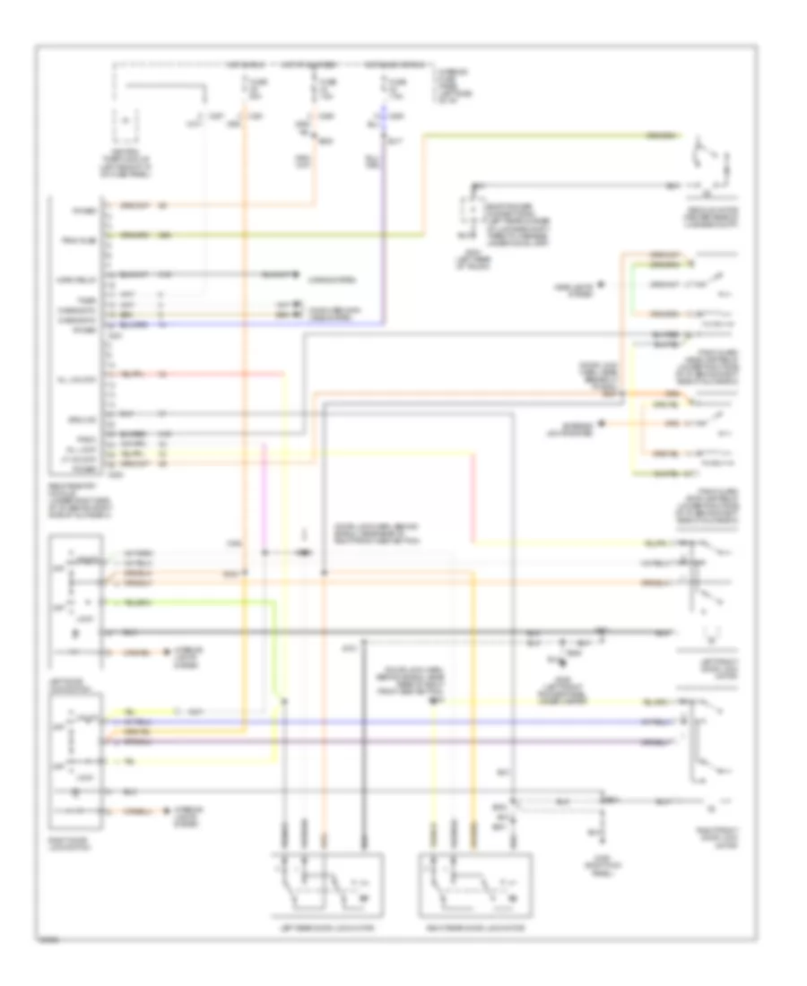
AIR CONDITIONING
A/C Wiring Diagram for Mercury Mystique 1997
 https://portal-diagnostov.com/license.html
Automotive Electricians Portal FZCO
Automotive Electricians Portal FZCO
https://portal-diagnostov.com/license.html
https://portal-diagnostov.com/license.html
Automotive Electricians Portal FZCO
Automotive Electricians Portal FZCO
List of elements for A/C Wiring Diagram for Mercury Mystique 1997:
- (behind bottom of right kick panel)
- (engine cooling fan harness, near electric cooling fan motor breakout)
- (fuse box harn, behind left side of i/p)
- (i/p harn, behind right center of i/p)
- (left front of engine compartment, behind headlamp)
- (right front of engine compartment, near headlamps)
- (right front of engine compt, near headlamps)
- 14s
- 2.0l
- 2.5l
- 91s
- A/c clutch cycling pressure switch (left front of engine compartment)
- A/c clutch diode
- A/c clutch relay (in engine compartment fuse box)
- A/c clutch solenoid
- A/c high pressure cutout/fan switch (right front corner of engine compartment)
- A/c wide open throttle relay (in engine compartment fuse box)
- Air temperature actuator (under right center of i/p, left of glove box)
- Air temperature control
- Backup lamps fuse 23 15a
- Blower motor
- Blower motor fuse 37 30a
- Blower motor relay
- Blower motor resistor (under right center of i/p)
- Blower switch
- C281
- Clutch switch
- Cool
- Cooling fan resistor (lower left corner of cooling fan shroud)
- Def
- Electric cooling fan motor
- Electric cooling fan motor #1
- Electric cooling fan motor #2
- Engine compartment fuse box
- Engine compt)
- Engine cooling fan fuse 2 60a
- Fan switch
- Flr
- Flr/def
- G100
- G100 (left front of engine compartment, behind headlamp)
- G101
- G101 (right front of engine compart- ment, near headlamps)
- G203
- G203 (behind bottom of right kick panel)
- Gearshift lever unit
- Heater/ a/c mode switch
- High speed cooling fan relay (in engine compartment fuse box)
- Hot at all times
- Hot in run or start
- Interior fuse panel
- Low speed cooling fan relay (in engine compartment fuse box)
- Max a/c
- Nca
- Norm a/c
- Off
- Pan/flr
- Pan/vnt
- Pcm power relay
- Powertrain control module (right rear corner of engine compartment)
- Red
- S107 (fuse box harn, left side of engine compt)
- S124
- S124 (engine cooling fan harness, near electric cooling fan motor breakout)
- S125 (engine cooling fan harn, right front side of engine compt)
- S126 (engine cooling fan harn, near a/c clutch solenoid)
- S167 (engine control harn, near pcm breakout)
- S171 (fuse box harn, front center of engine compt)
- S216 (i/p harn, near i/p cluster breakout)
- S218
- S223 (i/p harn, near main light sw breakout)
- S242
- S243 (fuse box harn, behind left side of i/p)
- S245 (i/p harn, near top of glove box)
- S247 (i/p harn, near top of glove box)
- Shorting bar connector #1 (behind left side of i/p)
- Shorting bar connector #3 (behind right side of i/p)
- Warm
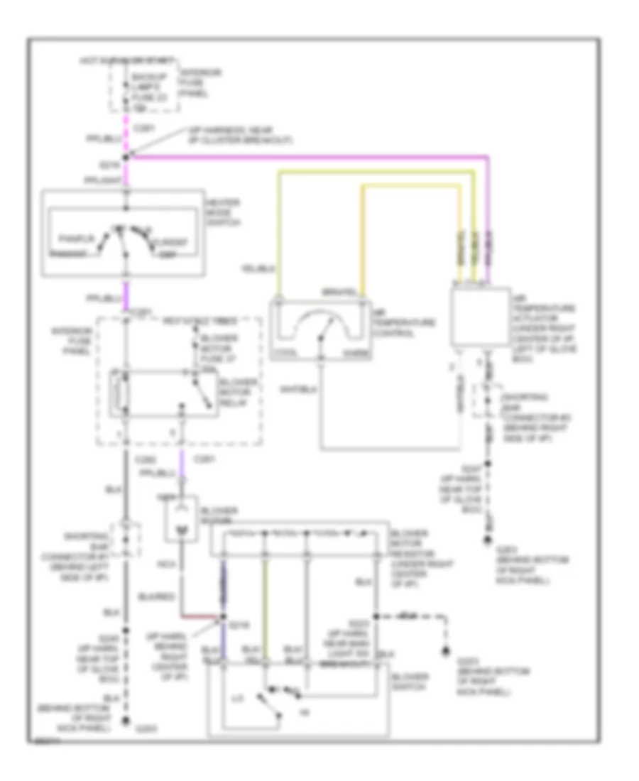
Heater Wiring Diagram for Mercury Mystique 1997
List of elements for Heater Wiring Diagram for Mercury Mystique 1997:
- (behind bottom
- (i/p harn, behind right center of i/p)
- (i/p harness, near i/p cluster breakout)
- Air temperature actuator (under right center of i/p, left of glove box)
- Air temperature control
- Backup lamps fuse 23 15a
- Blower motor
- Blower motor fuse 37 30a
- Blower motor relay
- Blower motor resistor (under right center of i/p)
- Blower switch
- C281
- C282
- Cool
- Def
- Flr
- Flr/def
- Fuse
- G203
- G203 (behind bottom of right kick panel)
- Heater mode switch
- Hot at all times
- Hot in run or start
- Interior
- Interior fuse panel
- Kick panel)
- Nca
- Of right
- Off
- Pan/flr
- Pan/vnt
- Panel
- S216
- S218
- S223 (i/p harn, near main light sw breakout)
- S245 (i/p harn, near top of glove box)
- Shorting bar connector #1 (behind left side of i/p)
- Shorting bar connector #3 (behind right side of i/p)
- Warm
ANTI-LOCK BRAKES
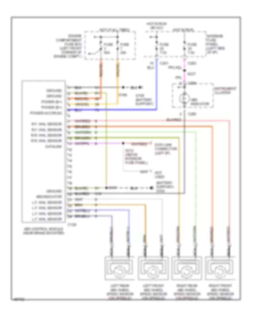
All-Wheel ABS Wiring Diagram, with MEC III for Mercury Mystique 1997
List of elements for All-Wheel ABS Wiring Diagram, with MEC III for Mercury Mystique 1997:
- (battery support) g100
- 31s
- Abs control module (near brake booster)
- Abs indicator
- C129
- C201
- C283
- C290
- Data link connector (left i/p)
- Datalink
- Engine compartment fuse box (left front corner of engine compt.)
- Fuse 20a
- Fuse 60a
- Fuse 7.5a
- G100 (battery support)
- Ground
- Hot at all times
- Hot in run
- Hot in run or acc
- Instrument cluster
- Interior fuse panel (left side of i/p)
- L.f. whl sensor
- Left front abs wheel speed sensor (on spindle)
- Left rear abs wheel speed sensor (on spindle)
- Nca
- Not used
- Power (acc/run)
- Power (b+)
- R.f. whl sensor
- R.r. whl sensor
- Right front abs wheel speed sensor (on spindle)
- Right rear abs wheel speed sensor (on spindle)
- S197
- S199
- S212 (above interior fuse panel)
- S237
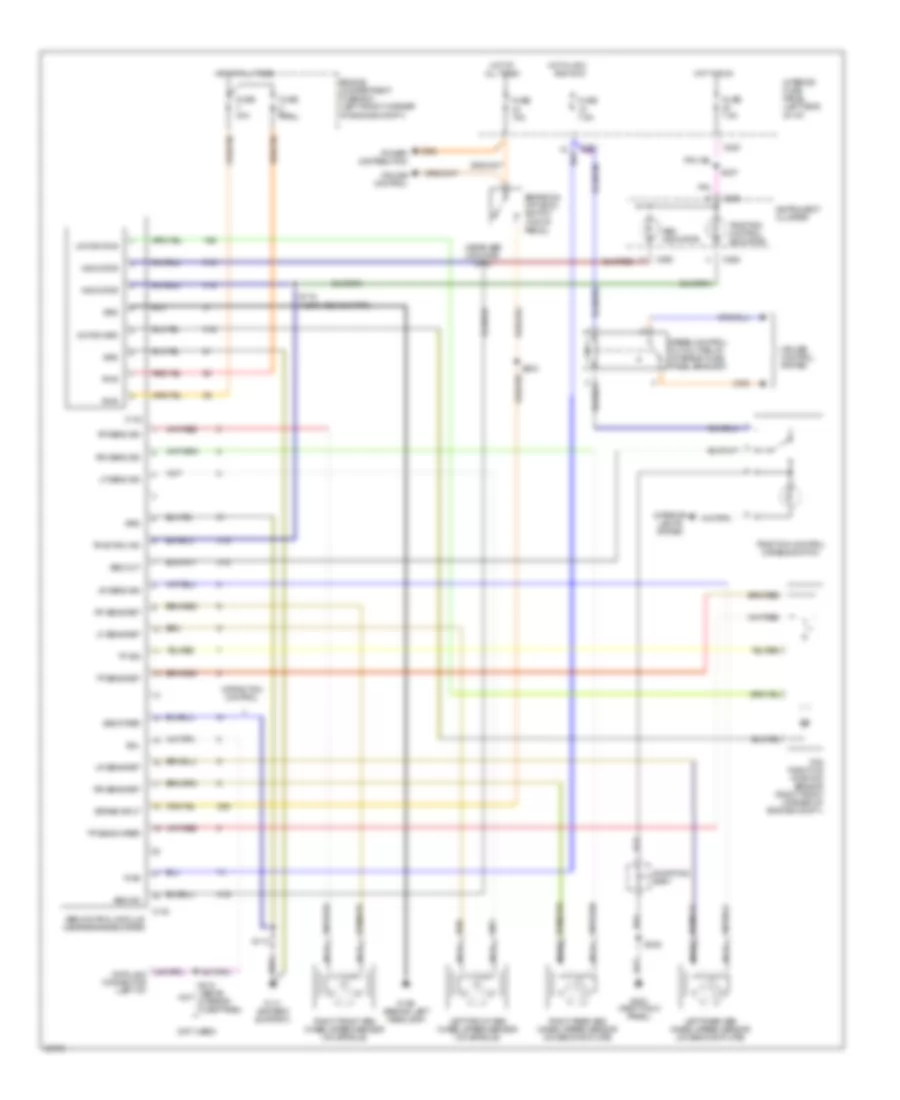
All-Wheel ABS Wiring Diagram, with Traction Control for Mercury Mystique 1997
List of elements for All-Wheel ABS Wiring Diagram, with Traction Control for Mercury Mystique 1997:
- (near abs monitor) s109
- (not used)
- 15s
- 29s
- 31s
- Abs control module (near brake booster)
- Abs ind
- Abs indicator
- All times
- And run
- Brake input
- Brake on/ off (boo) switch (top of pedal)
- C130
- C132
- C201
- C262
- C283
- C290
- Cruise control
- Cruise control system
- Engine compartment fuse box (left front corner of engine compt.)
- Fuse 15a
- Fuse 30a
- Fuse 60a
- Fuse 7.5a
- G106 (behind left headlamp)
- G111 (battery support)
- G203 (right kick panel)
- Grd
- Hot at
- Hot at all times
- Hot in acc
- Hot in run
- Identifier
- Indicator
- Instrument cluster
- Interior fuse panel (left side of i/p)
- Interior lights system
- Left front abs wheel speed sensor (on spindle)
- Left rear abs wheel speed sensor (on backing plate)
- Lf sens ret
- Lf sens sig
- Lr sens ret
- Lr sens sig
- Motor grd
- Motor pwr
- Nca
- Power distribution
- Pwr
- Rf sens ret
- Rf sens sig
- Right front abs wheel speed sensor (on spindle)
- Right rear abs wheel speed sensor (on backing plate)
- Rr sens ret
- Rr sens sig
- S113
- S115 (near abs monitor)
- S203
- S212 (above interior fuse panel)
- S237
- S245
- Sdl
- Seq out
- Shorting bar 1
- Speed control cut-out relay (interior fuse panel bracket)
- Tcs throttle position sensor (right front corner of engine compt.)
- Tp sens ret
- Tp sens wiper
- Tp sig
- Traction control disable switch
- Traction control indicator
- Traction ind
- W/traction control
COMPUTER DATA LINES
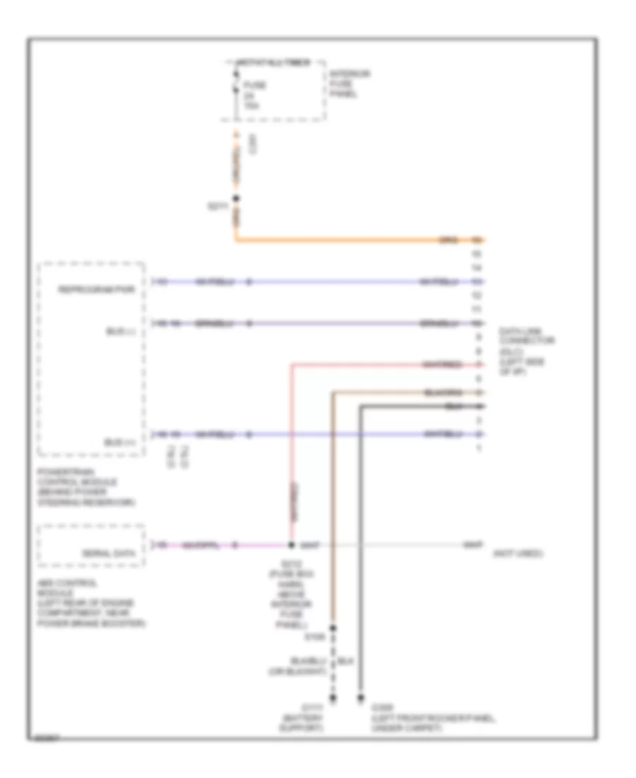
Computer Data Lines for Mercury Mystique 1997
List of elements for Computer Data Lines for Mercury Mystique 1997:
- (2.0l)
- (2.5l)
- (not used)
- Abs control module (left rear of engine compartment, near power brake booster)
- Bus (+)
- Bus (-)
- C201
- Data link connector (dlc) (left side of i/p)
- Fuse 15a
- G111 (battery support)
- G309 (left front rocker panel, under carpet)
- Hot at all times
- Interior fuse panel
- Powertrain control module (behind power steering reservoir)
- Reprogram pwr
- S106
- S211
- S212 (fuse box harn, above interior fuse panel)
- Serial data
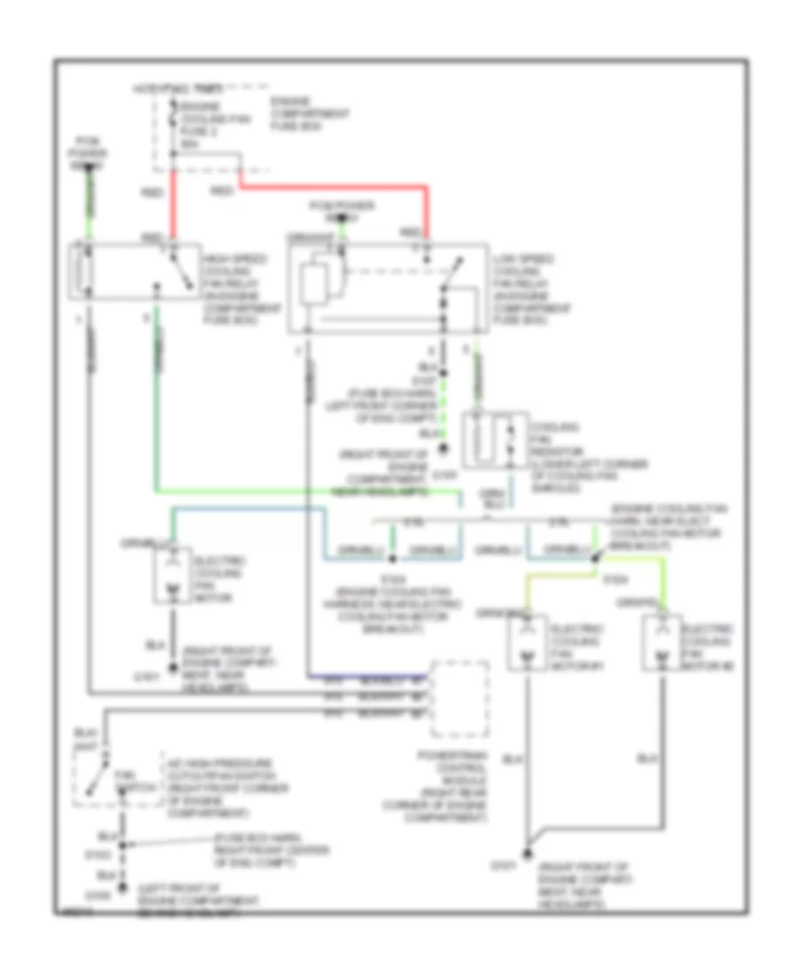
COOLING FAN
Cooling Fan Wiring Diagram for Mercury Mystique 1997
List of elements for Cooling Fan Wiring Diagram for Mercury Mystique 1997:
- (engine cooling fan harn, near elect cooling fan motor breakout)
- (fuse box harn, right front center of eng compt)
- (left front of engine compartment, behind headlamp)
- (right front of engine compart- ment, near headlamps)
- (right front of engine compartment, near headlamps)
- 2.0l
- 2.5l
- 91s
- A/c high pressure cutout/fan switch (right front corner of engine compartment)
- Cooling fan resistor (lower left corner of cooling fan shroud)
- Electric cooling fan motor
- Electric cooling fan motor #1
- Electric cooling fan motor #2
- Engine compartment fuse box
- Engine cooling fan fuse 2 60a
- Fan switch
- G100
- G101
- High speed cooling fan relay (in engine compartment fuse box)
- Hot at all times
- Low speed cooling fan relay (in engine compartment fuse box)
- Pcm power relay
- Powertrain control module (right rear corner of engine compartment)
- Red
- S103
- S107 (fuse box harn, left front corner of eng compt)
- S124
- S124 (engine cooling fan harness, near electric cooling fan motor breakout)
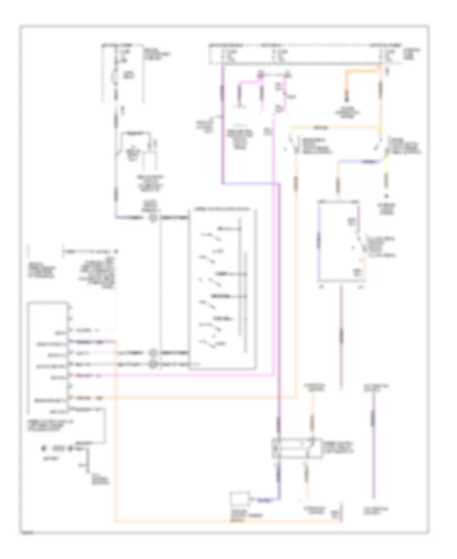
CRUISE CONTROL
Cruise Control Wiring Diagram for Mercury Mystique 1997
List of elements for Cruise Control Wiring Diagram for Mercury Mystique 1997:
- 29s
- A/t
- Battery
- Brake on/off switch (top of brake pedal support)
- Brake pedal switch (top of brake pedal support)
- C136
- C201
- C221
- Clock- spring assembly
- Clutch pedal position switch (top of clutch pedal)
- Coast
- Deactivation in
- Engine compartment fuse box
- Exterior lights system
- Fuse 15a
- Fuse 7.5a
- G111 (battery support)
- Ground
- Horn
- Horn relay
- Hot at all times
- Hot in acc or run
- Hot in run
- Ignition
- Interior fuse panel
- M/t
- Nca
- Off
- Park/neutral position (pnp) switch (top of trans)
- Power distribution system
- Remote entry module (under right side of i/p)
- Resume
- S204 (fuse box harn, near safety wall harn, in breakout to 8 pin inline connector, above interior fuse panel)
- S205
- Set/accel
- Speed control cutout relay (left side of i/p)
- Speed control module (left rear corner of engine compt)
- Speed control/horn switch
- Switch in
- Switch return
- Traction control disable switch
- Vehicle speed sensor (lower rear of transaxle)
- Vss in
- W/ drl
- W/ remote entry only
- W/ traction control only
- W/o drl
- W/o traction control
- W/traction control
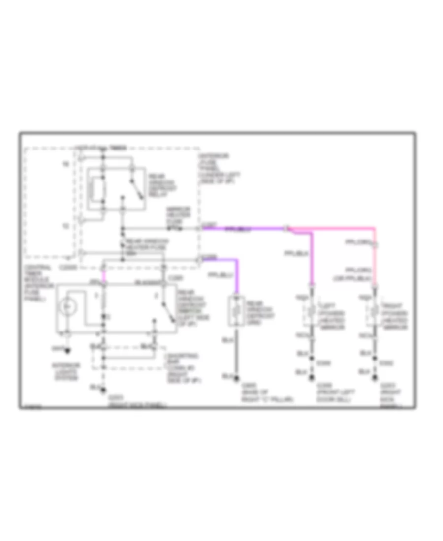
DEFOGGERS
Defogger Wiring Diagram for Mercury Mystique 1997
List of elements for Defogger Wiring Diagram for Mercury Mystique 1997:
- C2005
- C285
- C287
- C299
- Central timer module (interior fuse panel)
- G203 (right kick panel)
- G309 (front left door sill)
- G905 (base of right "c" pillar)
- Hot at all times
- Interior fuse panel (under left side of i/p)
- Interior lights system
- Left power/ heated mirror
- Mirror heater fuse 7.5a
- Nca
- Rear window defrost grid
- Rear window defrost relay
- Rear window defrost switch switch (left side of i/p)
- Rear window heater fuse 30a
- Right power/ heated mirror
- S302
- S306
- Shorting bar conn. #3 (right side of i/p)
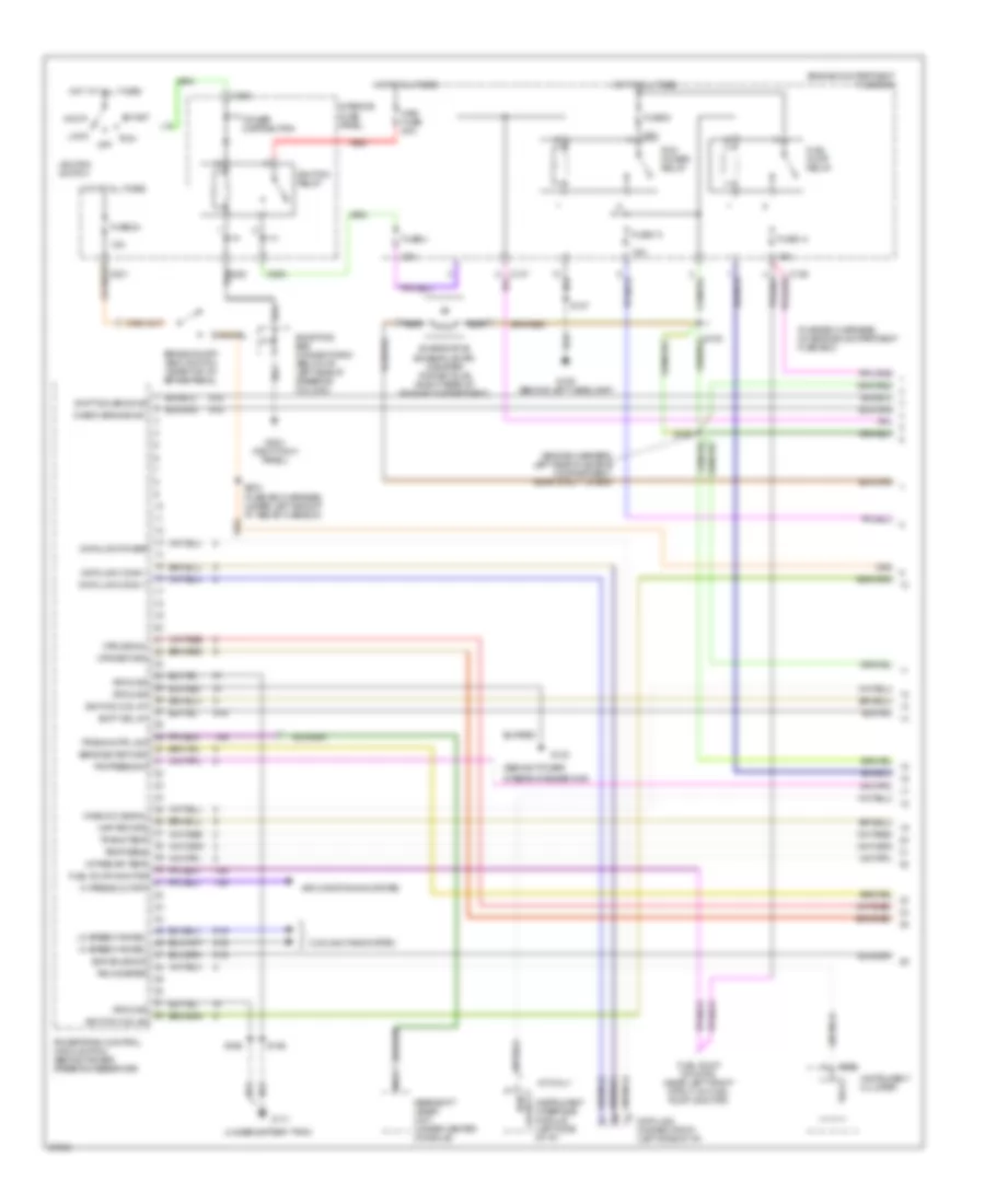
ENGINE PERFORMANCE
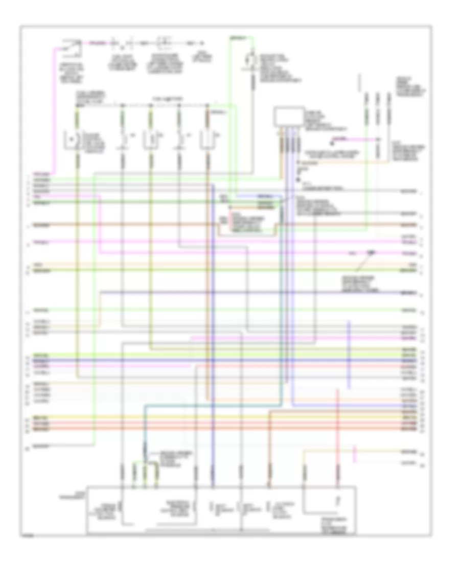
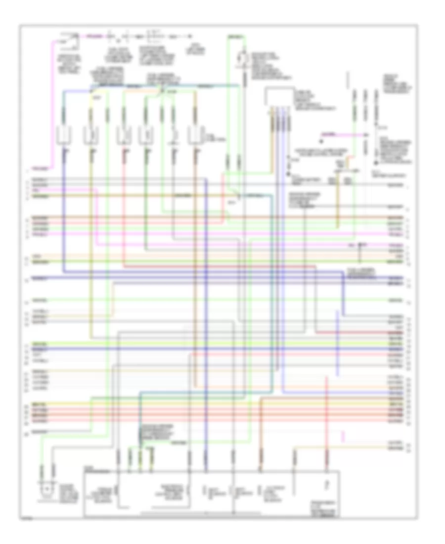
2.0L
2.0L, Engine Performance Wiring Diagrams (1 of 4) for Mercury Mystique 1997
List of elements for 2.0L, Engine Performance Wiring Diagrams (1 of 4) for Mercury Mystique 1997:
- (behind power
- (engine harness, left side of engine compartment, near strut tower)
- (fuse box harness, on engine compartment fuse box)
- (under battery tray)
- 14s
- 15a
- 20a
- 91s
- A/t only
- Acc
- Air conditioning system
- Brake on/off (boo) switch (near top of brake pedal)
- C201
- C205
- C262
- C288
- Check engine ind.
- Cooling fans system
- Cps return
- Cps signal
- Data link conn +
- Data link conn -
- Data link connector #1 (left side of i/p)
- Data link power
- Engine compartment fuse box
- Evaporative emission (evap) canister purge valve (right rear of engine compartment)
- Evr solenoid
- Fuel pump monitor
- Fuel pump monitor (near left front strut, on fuel pump monitor)
- Fuel pump relay
- Fuse 13
- Fuse 14
- Fuse 24
- Fuse 4
- Fuse 9
- G106 (behind left headlamp)
- G111
- G123
- G203 (right kick panel)
- Gearshift lever unit (under center console)
- Ground
- Hi press cutoff
- Hi speed fan rel
- Hos2 #12 signal
- Hot at all times
- Ignition coil #1
- Ignition coil #2
- Ignition relay
- Ignition switch
- Instrument cluster
- Instrument interface module (left side of i/p)
- Intake air temp
- Interior fuse panel
- Lo speed fan rel
- Lock
- Maf return
- Main fuse 80a
- Nca
- Off
- P/s press sw
- Pcm output
- Pcm power relay
- Power distribution
- Powertrain control module (pcm) (behind power steering reservoir)
- Red
- Run
- S107
- S108
- S158
- S161
- S166
- S203 (fuse box harness, under left side of i/p, above fuse box)
- Sens sig return
- Shift sol #1
- Shift solenoid #2
- Shorting bar connector #1 (below i/p, left side of steering column)
- Start
- Tach
- Tachometer
- Temp sens
- Trans cntrl sw
- Trans temp
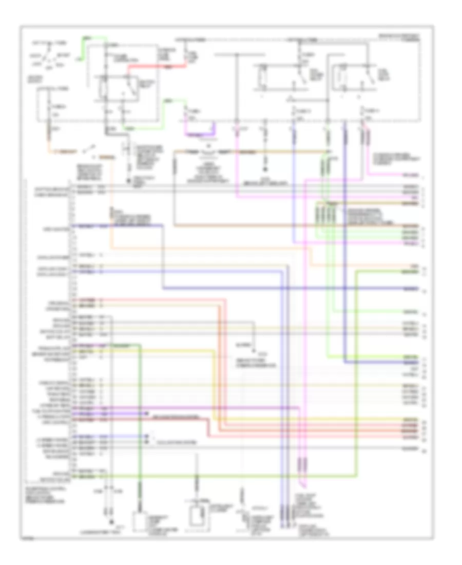
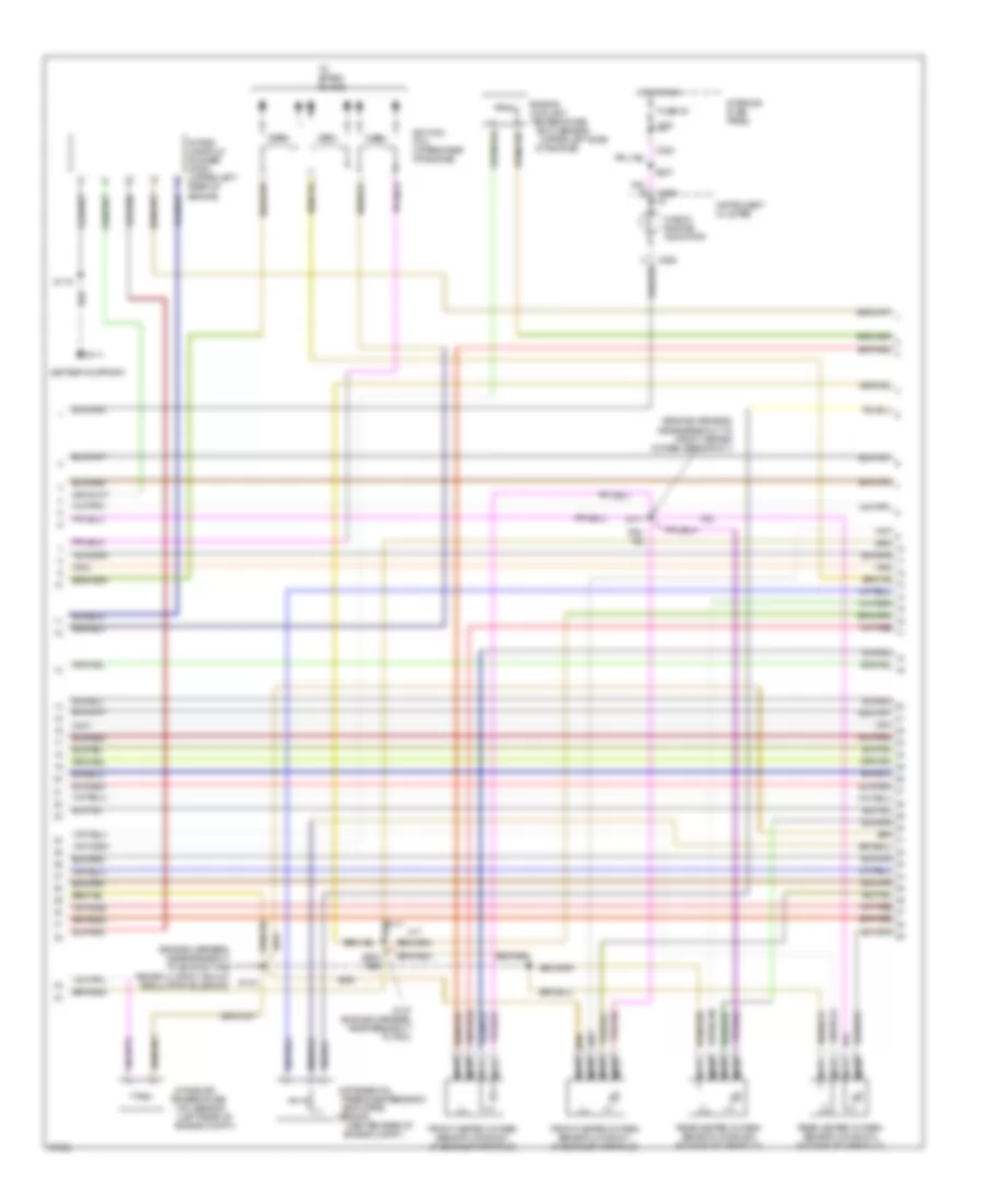
2.0L, Engine Performance Wiring Diagrams (2 of 4) for Mercury Mystique 1997
List of elements for 2.0L, Engine Performance Wiring Diagrams (2 of 4) for Mercury Mystique 1997:
- (engine harness, in breakout to to cd4e transaxle)
- (engine harness, near breakout to 42-pin conn, near strut tower)
- (fuel harness, near breakout to fuel inj #5) s129
- 3-2 timing/
- Cd4e transmission
- Clutch (tcc)
- Coast clutch
- Control (epc)
- Converter
- Electronic
- Exhaust gas recirculation vacuum regulator (evr) solenoid (center rear of engine compartment)
- Fluid
- Fuel injectors
- Fuel pump (fp) module (under center of rear seat)
- G111 (under battery tray)
- G404 (left rear of trunk)
- Idle air control (iac) valve (on intake manifold)
- Inertia fuel shutoff (ifs) switch (behind left kick panel)
- Instrument cluster system cruise control system
- Mass air flow (maf) sensor (left rear of engine compartment)
- Nca
- Near breakout to egr vacuum regulator sol)
- Pressure
- S133
- S153
- S154 (engine harness, near end of shield, toward breakout to vehicle speed sensor)
- S157 (engine harness, near breakout to intake air temp sensor)
- Shift
- Shorting bar connector #4 (left rear corner of luggage compt, under comb lamp)
- Solenoid
- Temperature (tft) sensor
- Torque
- Transmission
- Vehicle speed sensor (vss) (lower rear of transmission)
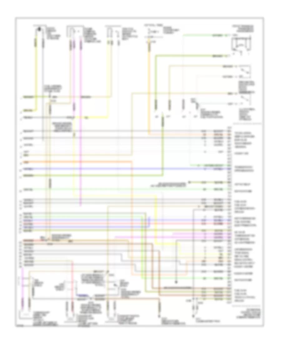
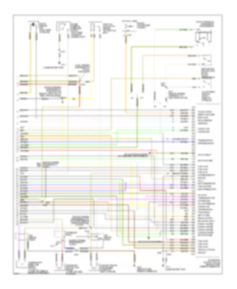
2.0L, Engine Performance Wiring Diagrams (3 of 4) for Mercury Mystique 1997
List of elements for 2.0L, Engine Performance Wiring Diagrams (3 of 4) for Mercury Mystique 1997:
- (center rear of
- (in exhaust
- (left rear of
- (upper left side
- 7.5a
- C262
- C283
- C290
- Check engine indicator
- Coolant
- Differential
- Egr (dpfe)
- Engine
- Engine compt.)
- Front
- Fuse 30
- Heated oxygen sensor (ho2s)
- Hot in run
- Ignition coil
- Instrument cluster
- Intake air
- Interior fuse panel
- Manifold)
- Nca
- Of engine)
- Pressure feedback
- Rear
- S156 (engine harness in breakout to intake air temp sensor)
- S164 (engine harness, near breakout to 42-pin black conn, near strut tower)
- S237
- Sensor
- Temperature (ect) sensor
- Temperature (iat) sensor
- To spark plugs
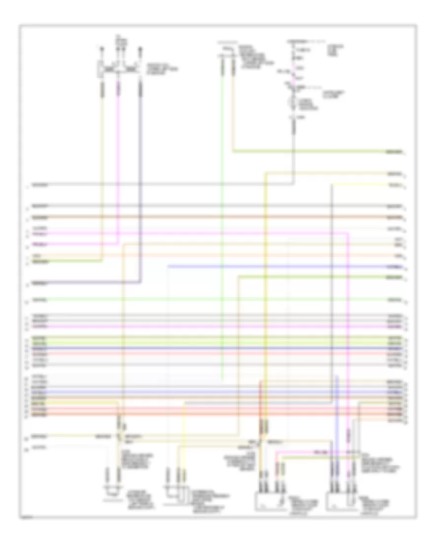
2.0L, Engine Performance Wiring Diagrams (4 of 4) for Mercury Mystique 1997
List of elements for 2.0L, Engine Performance Wiring Diagrams (4 of 4) for Mercury Mystique 1997:
- (a/t: near breakout to power steering pressure sensor) m/t: near breakout to pcm)
- (engine harness, near breakout to egr vacuum regulator sol)
- (engine harness, near breakout to pcm)
- (fuel harness, near breakout to fuel inj #3)
- (top of transaxle) transmission range sensor
- 29s
- 91s
- A/c high press sw
- A/t
- Air conditioning system
- Air conditioning system (a/c wide open throttle relay)
- Boo switch input
- Camshaft positon (cmp) sensor (upper left rear of engine)
- Ckp sensor shield
- Clutch pedal position switch (near top of pedals)
- Cmp sens return
- Cmp sens sig
- Cmp sensor shield
- Crankshaft position (ckp) sensor (lower left side of engine)
- Dpfe sensor sig
- Elect press cntrl
- Engine compartment fuse box
- Evap valve
- Fuel inj #1
- Fuel inj #2
- Fuel inj #3
- Fuel inj #4
- Fuel pump rel
- Fuse 11
- G111 (under battery tray)
- G123 (behind power steering reservoir)
- Ground
- Ho2s #11 heater
- Ho2s #11 sig
- Ho2s #12 heater
- Hot at all times
- Iac valve
- Ignition power
- Inst interface sig
- Keep alive power
- Knock sensor
- Knock sensor (ks) (right rear of engine)
- M/t
- Maf sensor sig
- Park/neutral position (pnp) switch (top of transmission)
- Power steering pressure sensor (on power steering line)
- Powertrain control module (behind power steering reservoir)
- Ref voltage
- S128
- S147 (engine harness, in breakout to fuel pump monitor)
- S148
- S149 (engine harness, near breakout to power steering pressure sensor)
- S150
- S158
- S162 (engine harness, near breakout to pcm)
- S163
- S166
- Signal control
- Tcc sol signal
- Throttle position (tp) sensor (on throttle body)
- Timing clutch sol
- Tp sig signal
- Tr sens/pnp sw
- Turbine shaft sig
- Turbine shaft speed (tss) sensor (a/t only) (lower left rear of engine compartment)
- Vss signal
- Wot a/c relay
2.5L
2.5L, Engine Performance Wiring Diagrams (1 of 4) for Mercury Mystique 1997
List of elements for 2.5L, Engine Performance Wiring Diagrams (1 of 4) for Mercury Mystique 1997:
- (behind power
- (engine harness, near breakout to 42-pin black conn, near left strut tower)
- (fuse box harness, on engine compartment fuse box)
- (right kick panel) g203
- (under battery tray)
- 14s
- 15a
- 20a
- 91s
- A/t only
- Acc
- Air conditioning system
- Brake on/off (boo) switch (near top of brake pedal)
- C201
- C205
- C262
- C288
- Check engine ind.
- Cooling fans system
- Cps return
- Cps signal
- Data link conn +
- Data link conn -
- Data link connector #1 (left side of i/p)
- Data link power
- Engine compartment fuse box
- Evr solenoid
- Fuel pump monitor
- Fuel pump monitor (near left front strut, on fuel pump monitor)
- Fuel pump relay
- Fuse 13
- Fuse 14
- Fuse 24
- Fuse 4
- Fuse 9
- G106 (behind left headlamp)
- G111
- G123
- Gearshift lever unit (under center console)
- Ground
- Hi press cutoff
- Hi speed fan rel
- Hos2 #12 signal
- Hot at all times
- Ignition coil #1
- Ignition coil #2
- Ignition relay
- Ignition switch
- Imrc control
- Imrc monitor
- Instrument cluster
- Instrument interface module (left side of i/p)
- Intake air temp
- Interior fuse panel
- Lo speed fan rel
- Lock
- Maf return
- Main fuse 80a
- Nca
- Off
- P/s press sw
- Pcm output
- Pcm power relay
- Power distribution
- Powertrain control module (pcm) (behind power steering reservoir)
- Red
- Run
- S158
- S161
- S166
- S203 (fuse box harness, under left side of i/p, above fuse box)
- Sensor sig return
- Shift sol #1
- Shift solenoid #2
- Shorting bar connector #1 (below i/p, left side of steering column)
- Start
- Tach
- Tachometer
- Temp sens
- Trans cntrl sw
- Trans temp
- Vapor management valve (vmv) (right rear of engine compartment)
2.5L, Engine Performance Wiring Diagrams (2 of 4) for Mercury Mystique 1997
List of elements for 2.5L, Engine Performance Wiring Diagrams (2 of 4) for Mercury Mystique 1997:
- (engine harness, near breakout to mass air flow sensor)
- (fuel harness, near breakout to fuel injector #5)
- (fuel harness, near breakout to ignition coil)
- 3-2 timing/
- A/t
- Cd4e
- Clutch (tcc)
- Coast clutch
- Control (epc)
- Converter
- Electronic
- Exhaust gas recirculation vacuum regulator (evr) solenoid (center rear of engine compartment)
- Fluid
- Fuel injectors
- Fuel pump (fp) module (under center of rear seat)
- G111 (battery support)
- G111 (under battery tray)
- G404 (left rear of trunk)
- Idle air control (iac) valve (on intake manifold)
- Inertia fuel shutoff (ifs) switch (behind left kick panel)
- Instrument cluster system cruise control system
- M/t
- Mass air flow (maf) sensor (left rear of engine compartment)
- Nca
- Pressure
- Recirculation vacuum reg- ulator solenoid)
- S119
- S127
- S129
- S133
- S141
- S158
- Shift
- Shorting bar connector #4 (left rear corner of luggage compt, under comb lamp)
- Solenoid
- Temperature (tft) sensor
- Torque
- Transmission
- Vehicle speed sensor (vss) (lower rear of transmission)
2.5L, Engine Performance Wiring Diagrams (3 of 4) for Mercury Mystique 1997
List of elements for 2.5L, Engine Performance Wiring Diagrams (3 of 4) for Mercury Mystique 1997:
- (battery support)
- (center rear of
- (engine harness, near breakout to exhaust gas recirculation vacuum regulator solenoid)
- (engine harness, near breakout to front heated oxygen sensor #11)
- (left rear of
- (upper left side
- 7.5a
- C262
- C283
- C290
- Check engine indicator
- Coolant
- Differential
- Egr (dpfe)
- Engine
- Engine compt.)
- Front heated oxygen sensor (ho2s) #11 (in exhaust manifold)
- Front heated oxygen sensor (ho2s) #21 (in exhaust manifold)
- Fuse 30
- G111
- Hot in run
- Ignition coil (upper rear of engine)
- Instrument cluster
- Intake air
- Intake manifold runner (imrc) (upper left rear of engine)
- Interior fuse panel
- M/t
- Nca
- Of engine)
- Pressure feedback
- Rear heated oxygen sensor (ho2s) #12 (in exhaust manifold)
- Rear heated oxygen sensor (ho2s) #22 (in exhaust manifold)
- S117
- S119
- S137 (engine harness, near breakout to pcm)
- S144
- S237
- Sensor
- Temperature (ect) sensor
- Temperature (iat) sensor
- To spark plugs
2.5L, Engine Performance Wiring Diagrams (4 of 4) for Mercury Mystique 1997
List of elements for 2.5L, Engine Performance Wiring Diagrams (4 of 4) for Mercury Mystique 1997:
- (engine harness, near breakout to exhaust gas recirculation vacuum regulator solenoid) s143
- (engine harness, near breakout to pcm)
- (engine harness, near breakout to: a/t-power steering pressure sensor,
- (fuel harness, near breakout to fuel injector #2)
- (top of transaxle) transmission range sensor
- (under battery tray)
- 29s
- 91s
- A/c high press sw
- A/t
- Air conditioning system
- Air conditioning system (a/c wide open throttle relay)
- Boo switch input
- Camshaft positon (cmp) sensor (upper left rear of engine)
- Ckp sensor shield
- Clutch pedal position switch (near top of pedals)
- Cmp sens return
- Cmp sens sig
- Cmp sensor shield
- Coil c
- Crankshaft position (ckp) sensor (lower left side of engine)
- Dpfe sensor sig
- Elect press cntrl
- Engine compartment fuse box
- Evap valve
- Fuel inj #1
- Fuel inj #2
- Fuel inj #3
- Fuel inj #4
- Fuel inj #5
- Fuel inj #6
- Fuel pump rel
- Fuse 11
- G111
- G123 (behind power steering reservoir)
- Ground
- Ho2s #11 heater
- Ho2s #11 sig
- Ho2s #12 heater
- Ho2s #21 heater
- Ho2s #21 sig
- Ho2s #22 heater
- Ho2s #22 sig
- Hot at all times
- Iac valve
- Ignition power
- Inst interface sig
- Keep alive power
- Knock sensor
- Knock sensor (ks) (right rear of engine)
- M/t
- M/t-pcm)
- Maf sensor sig
- Park/neutral position (pnp) switch (top of transmission)
- Power steering pressure switch (right rear corner of engine compt.)
- Powertrain control module (behind power steering reservoir)
- Ref voltage
- S111
- S112
- S119
- S128
- S138
- S147 (engine harness, in breakout to fuel pump monitor)
- S158
- S162
- S163
- S166
- S168
- Signal control
- Tcc sol signal
- Throttle position (tp) sensor (on throttle body)
- Timing clutch sol
- Tp sig signal
- Tr sens/pnp sw
- Turbine shaft sig
- Turbine shaft speed (tss) sensor (a/t only) (lower left rear of engine compartment)
- Vss signal
- Wot a/c relay
EXTERIOR LIGHTS
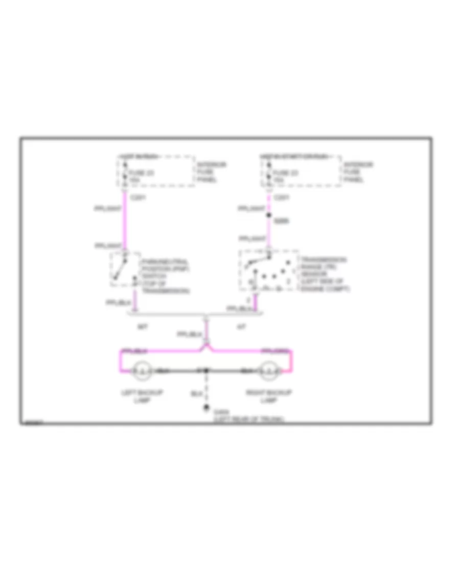
Back-up Lamps Wiring Diagram for Mercury Mystique 1997
List of elements for Back-up Lamps Wiring Diagram for Mercury Mystique 1997:
- A/t
- C201
- Fuse 23 15a
- G404 (left rear of trunk)
- Hot in run
- Hot in start or run
- Interior fuse panel
- Left backup lamp
- M/t
- Park/neutral position (pnp) switch (top of transmission)
- Right backup lamp
- S205 s205
- S401
- Transmission range (tr) sensor (left side of engine compt)
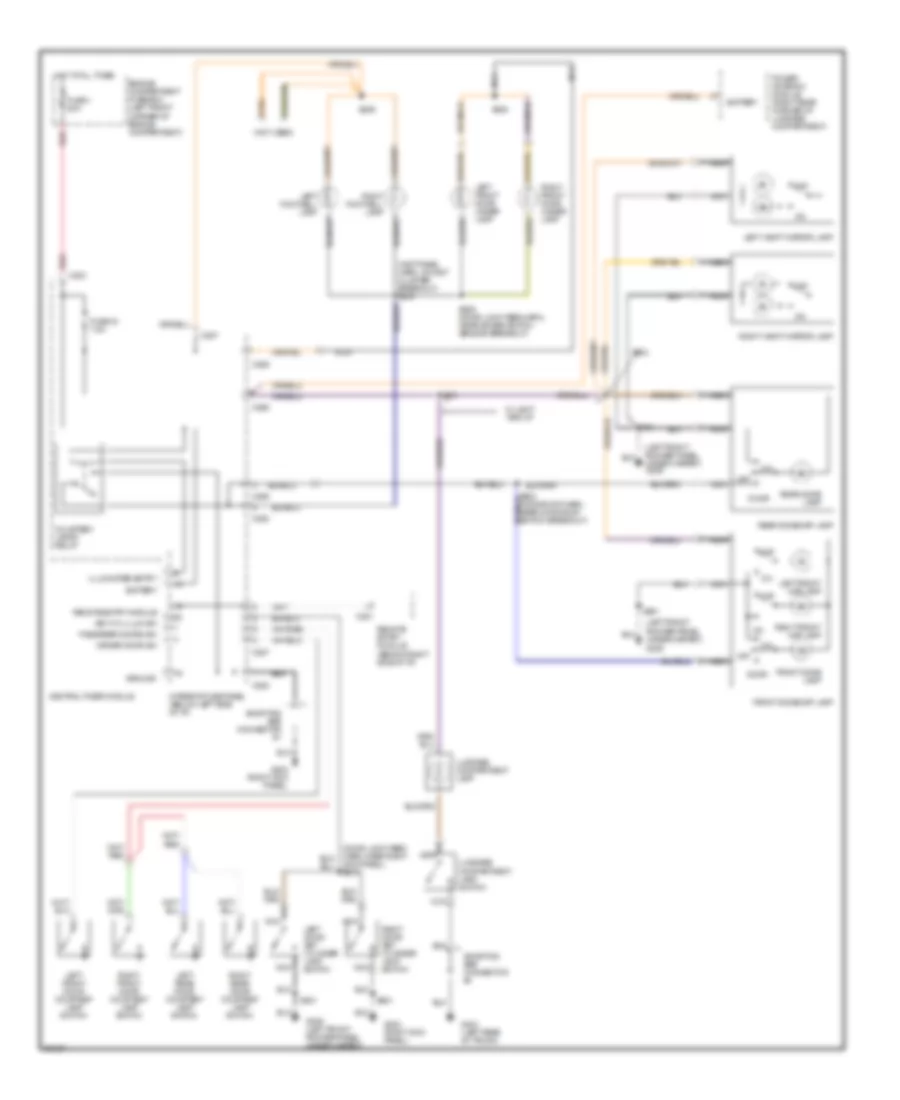
Exterior Lamps Wiring Diagram for Mercury Mystique 1997
List of elements for Exterior Lamps Wiring Diagram for Mercury Mystique 1997:
- (behind left headlamp)
- (behind right headlamp)
- (left rear of trunk)
- (not used)
- Brake on/off (boo) switch (top of brake pedal)
- C136
- C137
- C201
- C2013
- C262
- C276
- C277
- C282
- C283
- C288
- C298
- Combination switch
- Door locks system (remote keyless entry)
- Engine compartment fuse box (left front corner of engine compt.)
- Flasher module
- Front park lamp
- Front turn lamp
- Fuse 10 20a
- Fuse 12 15a
- Fuse 23 15a
- Fuse 24 15a
- Fuse 31 7.5a
- Fuse 33 7.5a
- Fuse 35 7.5a
- G106
- G107
- G203 (right kick panel)
- G404
- Hazard switch
- Head
- Headlamp switch
- Hi mount stop lamp
- Hot at all times
- Hot in start or run
- Instrument cluster
- Interior fuse panel (under left side of i/p)
- Left front park/ turn lamp
- Left license lamp
- Left rear combi- nation lamp
- Left turn indi- cator
- Main light switch
- Nca
- Off
- Park
- Rear park lamp
- Rear turn/ stop lamp
- Red
- Resistance wire
- Right front park/ turn lamp
- Right license lamp
- Right rear combi- nation lamp
- Right turn indi- cator
- S101
- S103
- S173
- S175
- S201
- S211
- S245
- Shorting bar connector #1
- Shorting bar connector #3
- Shorting bar connector #4
- Turn signal switch
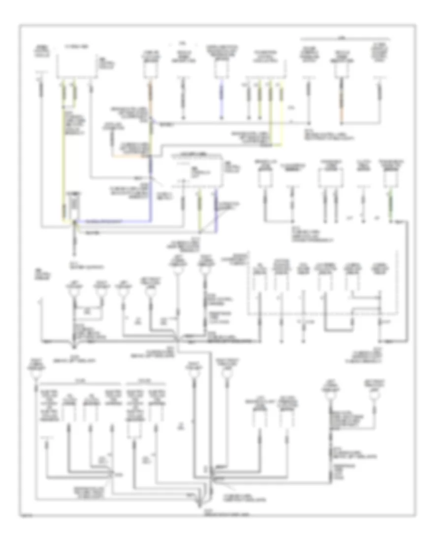
GROUND DISTRIBUTION
Ground Distribution Wiring Diagram (1 of 3) for Mercury Mystique 1997
List of elements for Ground Distribution Wiring Diagram (1 of 3) for Mercury Mystique 1997:
- (eng cntrl harn, right rear corner of eng compartment) s167
- (engine cntrl harn, left side of eng compartment) s166
- (engine cooling fan harn, front of eng compt)
- (fuse box harn, behind left headlamps)
- (fuse box harn, near right headlamps)
- 2.0l
- 2.5l
- 2.5l only
- A/c clutch diode
- A/c clutch relay
- A/c clutch solenoid
- A/c high pressure cutout/fan switch
- A/t
- Abs control module
- Abs hydraulic unit
- Battery
- Brake fluid level switch
- C136
- Clockspring assembly
- Clutch pedal switch
- Data link connector
- Daytime running lamps (drl) relay
- Electric cooling fan motor #1 or electric cooling fan motor
- Electric cooling fan motor #2
- Engine compartment fuse box
- G106 (behind left headlamp)
- G107 (behind right headlamp)
- G111 (battery support)
- Harness)
- Hi-beam headlamp relay
- Instrumentation engine coolant temperature sensor
- Intake manifold runner control (imrc)
- Left fog lamp
- Left front park/turn lamp
- Left hi-beam headlamp
- Left lo-beam headlamp
- Lo-beam headlamp relay
- Low engine coolant level switch
- Low speed cooling fan relay
- M/t
- Mass air flow (maf) sensor
- Nca
- Pcm power relay
- Power steering pressure switch
- Powertrain control module (pcm)
- Resistance wire 0.270 ohms
- Right fog lamp
- Right front park/turn lamp
- Right hi-beam headlamp
- Right lo-beam headlamp
- S101 (fuse box harn, behind left headlamps)
- S103
- S107 (fuse box harn, near eng compt fuse box breakout)
- S110 (fuse box harn, near data link connector breakout)
- S113 (fuse box harn, near abs monitor breakout)
- S119 (engine control harn, right front of eng compt)
- S125
- S168 (eng control nca
- S169 (fuse box harn, behind left headlamps)
- S170 nca
- S197 (fuse box harn, near abs cntrl module breakout)
- S199 (fuse box harn, near eng compt fuse box breakout)
- Speed control module
- Transmission range (tr) sensor
- Vehicle speed sensor (vss)
- W/ a/c
- W/ drl
- W/ mec iii abs
- W/ mec iii abs only
- W/o a/c
- W/o drl
- W/o mec iii abs
- W/traction control
- Windshield wiper motor
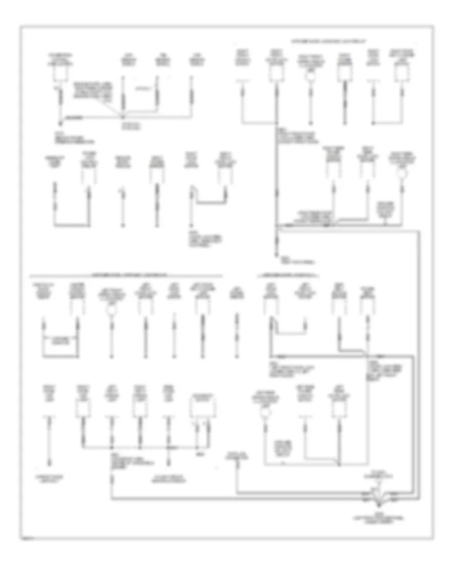
Ground Distribution Wiring Diagram (2 of 3) for Mercury Mystique 1997
List of elements for Ground Distribution Wiring Diagram (2 of 3) for Mercury Mystique 1997:
- (engine cntrl harn, right rear corner of eng compt) (2.0l) (engine cntrl harn) (2.5l)
- (right rear door lock feed harn, in right rear door) s801
- A/t only
- Ckp sensor shield
- Cmp sensor shield
- Data link connector
- Front dome/ map lamp
- G123 (behind power steering reservoir)
- G203 (right kick panel)
- G309 (left front rocker panel, under carpet)
- Gearshift lever unit
- Left door key cylinder lamp switch
- Left door lock switch
- Left front door lock motor
- Left front inside handle illumination lamp
- Left power mirror
- Left rear door lock motor
- Left rear inside handle illumination lamp
- Left rear power window switch
- Left vanity mirror lamp
- Master window control switch
- Moonroof switch
- Nca
- One touch down window relay
- Power lock control relay
- Power seat switch
- Powertrain control module (pcm)
- Rear dome/ map lamp
- Remote entry module
- Right door key cylinder lamp switch
- Right door lock switch
- Right front door lock motor
- Right front inside handle illumination lamp
- Right front window switch
- Right power mirror
- Right rear door lock motor
- Right rear inside handle illumination lamp
- Right rear power window switch
- Right vanity mirror lamp
- S149 (2.0l) s138 (2.5l)
- S302 (door lock feed harn, near right kick panel)
- S501 (left front door lock jumper harn, in left front door)
- S601 (right front door lock jumper harn, in right front door)
- S901 (moonroof harn, center of windshield header)
- S906
- Seat belt buckle switch
- Seat)
- To g404 (diagram 3 of 3)
- Tss sensor shield
- W/front dome lamp only
- W/light group and/or moonroof
- W/power door locks and light group
- W/power door locks only
- W/power windows
- W/power windows or light group
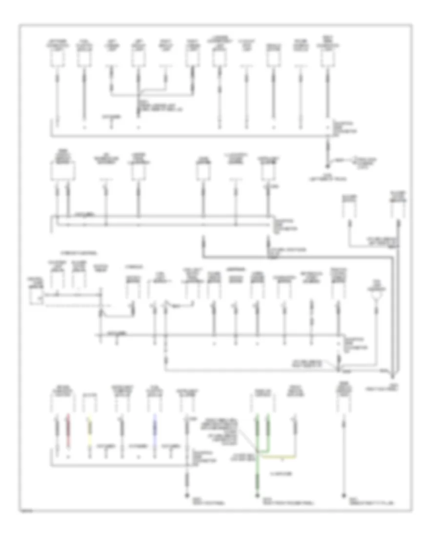
Ground Distribution Wiring Diagram (3 of 3) for Mercury Mystique 1997
List of elements for Ground Distribution Wiring Diagram (3 of 3) for Mercury Mystique 1997:
- (i/p harn, behind left side of i/p) s223
- (i/p harn, behind right side of i/p)
- (i/p harn, right side of i/p) s247
- (not used)
- (radio feed harn, near front remote amplifier breakout) (w/ amp) (i/p harn, behind center of i/p) (w/o amp)
- (w/ amp) s241 (w/o amp) s239
- Air bag diagnostic monitor
- Air temperature actuator
- Blower motor relay
- Blower motor resistor
- Blower switch
- Central timer module
- Cigar lighter
- Clock
- Combination switch
- Contour
- Courtesy lamp relay
- Decklid motor
- Fog lamp indicator
- From g309 (diagram 2 of 3)
- Front remote amplifier
- Fuel pump (fp) module
- G203 (right kick panel)
- G316 (right front rocker panel)
- G401 (base of right "c" pillar)
- G404 (left rear of trunk)
- Heater panel illumination
- Hi mount stop lamp
- Ignition relay
- Ignition switch
- Illumination dimmer control
- Instrument cluster
- Instrument interface module
- Interior fuse panel
- Key removal inhibit solenoid
- Left backup lamp
- Left license lamp
- Left rear combination lamp
- Luggage compartment lamp switch
- Main light switch
- Main light switch panel illumination
- Mystique
- Nca
- Power antenna module
- Power mirror switch
- Radio or cd/radio
- Rear window defrost grid
- Rear window defrost switch
- Right backup lamp
- Right license lamp
- Right rear combination lamp
- S245
- S401 (rear license lamp harn, rear of deck lid)
- Shorting bar connector #1
- Shorting bar connector #2
- Shorting bar connector #3
- Shorting bar connector #4
- Traction control disable switch
- W/ amplifier
- Wiper/ washer switch
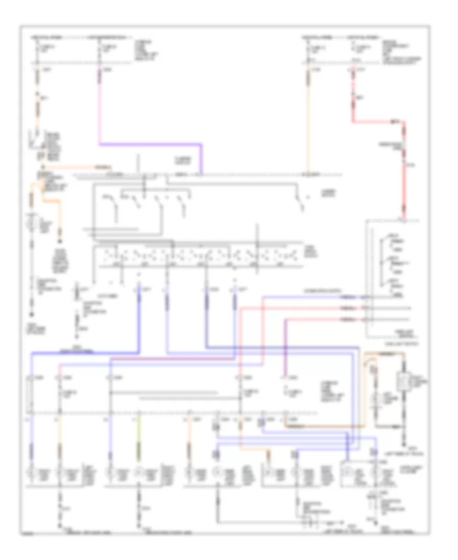
HEADLIGHTS
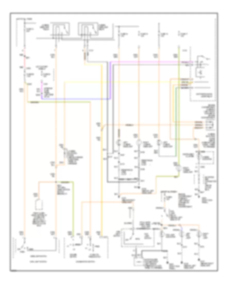
Headlight Wiring Diagram, with DRL for Mercury Mystique 1997
List of elements for Headlight Wiring Diagram, with DRL for Mercury Mystique 1997:
- (fog lamps harn, near fog lamp ind breakout)
- C134
- C137
- C201
- C262
- C277
- C282
- Combination switch
- Daytime running lamps relay
- Dimmer switch
- Engine compartment fuse box (left front corner of engine compartment)
- Engine compartment fuse box (left front corner of) engine compartment)
- Flash-to- pass switch
- Fog
- Fog lamp indicator
- Fog lamp relay (behind left side of i/p)
- Fog lamp switch
- Fuse 10 20a
- Fuse 15 10a
- Fuse 16 10a
- Fuse 17 10a
- Fuse 18 10a
- Fuse 23 15a
- Fuse 26 7.5a
- Fuse 5 15a
- G106 (behind left headlamp)
- G107 (behind right headlamp)
- G203 (right kick panel)
- Head
- Headlamp switch
- Hi beam blocking diode (above interior fuse panel, taped to harness)
- Hi beam headlamp relay
- Hi beam indicator
- Hot at all times
- Hot in start or run
- Instrument cluster
- Interior fuse panel (left side of i/p)
- Left fog lamp
- Left hi beam headlamp
- Left lo beam headlamp
- Lo beam blocking diode (above interior fuse panel, taped to harness)
- Lo beam headlamp relay
- Main light switch
- Off
- Panic alarm headlamp relay (w/ remote entry only) (behind right side of glove box)
- Park
- Pass
- Red
- Resistance wire (0.270
- Right fog lamp
- Right hi beam headlamp
- Right lo beam headlamp
- S101
- S103
- S107
- S167
- S168
- S169
- S170
- S201
- S205
- S224
- S234 (i/p harn, near ignition switch breakout)
- S245
- S247
- Shorting bar connector #1 (left side of steering column taped to harness)
- Shorting bar connector #3 (above glove box)
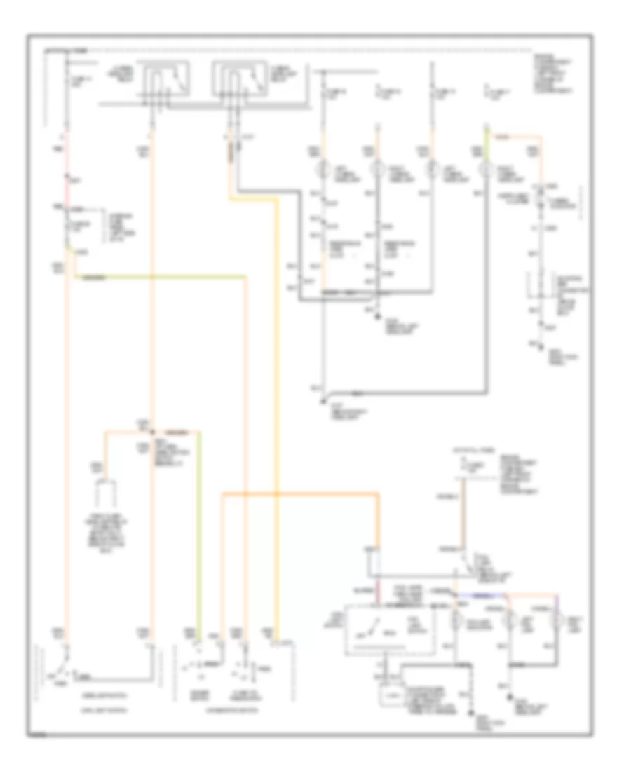
Headlight Wiring Diagram, without DRL for Mercury Mystique 1997
List of elements for Headlight Wiring Diagram, without DRL for Mercury Mystique 1997:
- (fog lamps harn, near fog lamp ind breakout)
- C134
- C137
- C262
- C277
- C282
- Combination switch
- Dimmer switch
- Engine compartment fuse box (left front corner of engine compartment)
- Engine compartment fuse box (left front corner of) engine compartment)
- Flash-to- pass switch
- Fog
- Fog lamp indicator
- Fog lamp relay (behind left side of i/p)
- Fog lamp switch
- Fuse 10 20a
- Fuse 15 10a
- Fuse 16 10a
- Fuse 17 10a
- Fuse 18 10a
- Fuse 26 7.5a
- Fuse 5 15a
- G106 (behind left headlamp)
- G107 (behind right headlamp)
- G203 (right kick panel)
- Head
- Headlamp switch
- Hi beam headlamp relay
- Hi beam indicator
- Hot at all times
- Instrument cluster
- Interior fuse panel (left side of i/p)
- Left fog lamp
- Left hi beam headlamp
- Left lo beam headlamp
- Lo beam headlamp relay
- Main light switch
- Off
- Panic alarm headlamp relay (w/ remote entry only) (behind right side of glove box)
- Park
- Pass
- Red
- Resistance wire (0.270
- Right fog lamp
- Right hi beam headlamp
- Right lo beam headlamp
- S101
- S102
- S103
- S107
- S167
- S168
- S169
- S170
- S201
- S234 (i/p harn, near ignition switch breakout)
- S245
- S247
- Shorting bar connector #1 (left side of steering column taped to harness)
- Shorting bar connector #3 (above glove box)
HORN
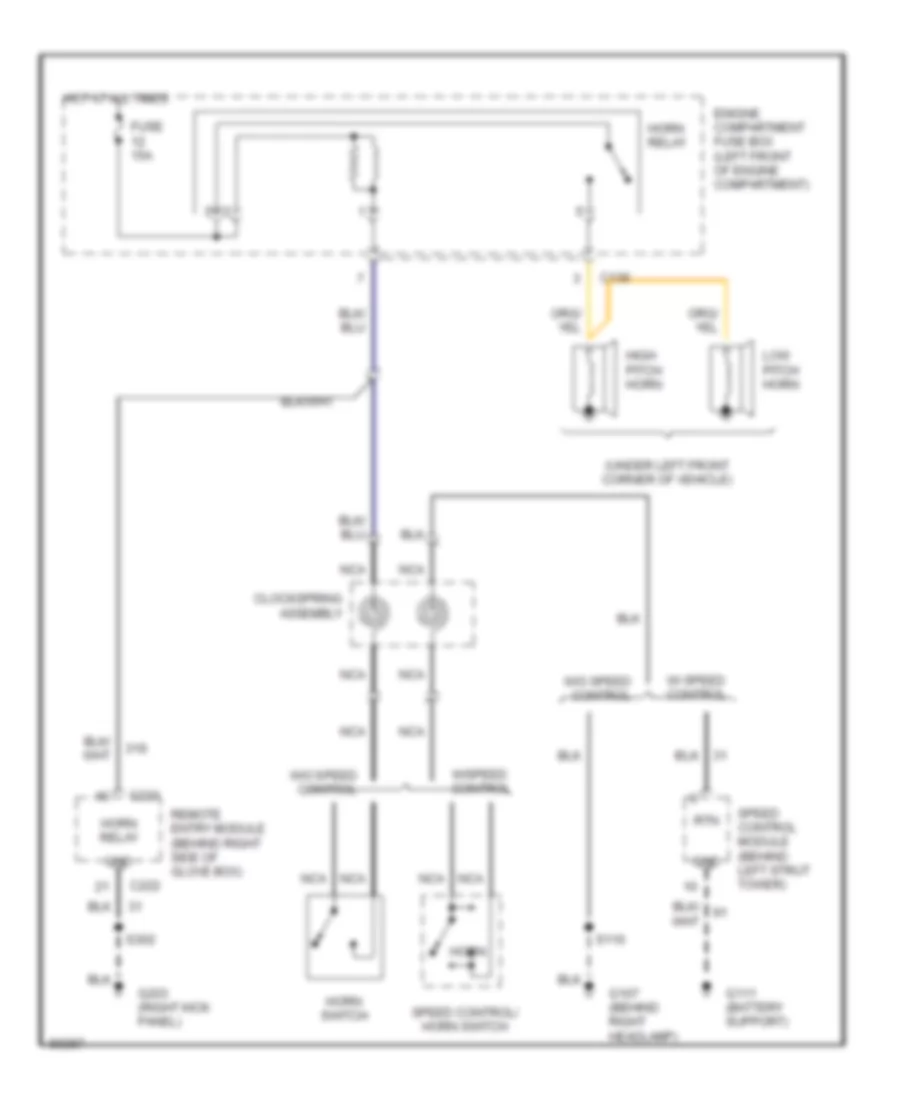
Horn Wiring Diagram for Mercury Mystique 1997
List of elements for Horn Wiring Diagram for Mercury Mystique 1997:
- (under left front corner of vehicle)
- 31s
- C136
- C221
- C222
- Clockspring assembly
- Enigne compartment fuse box (left front of engine compartment)
- Fuse 15a
- G107 (behind right headlamp)
- G111 (battery support)
- G203 (right kick panel)
- Gnd
- High pitch horn
- Horn
- Horn relay
- Horn switch
- Hot at all times
- Low pitch horn
- Nca
- Remote entry module (behind right side of glove box)
- Rtn
- S110
- S302
- Speed control module (behind left strut tower)
- Speed control/ horn switch
- W/ speed control
- W/o speed control
- W/speed control
INSTRUMENT CLUSTER
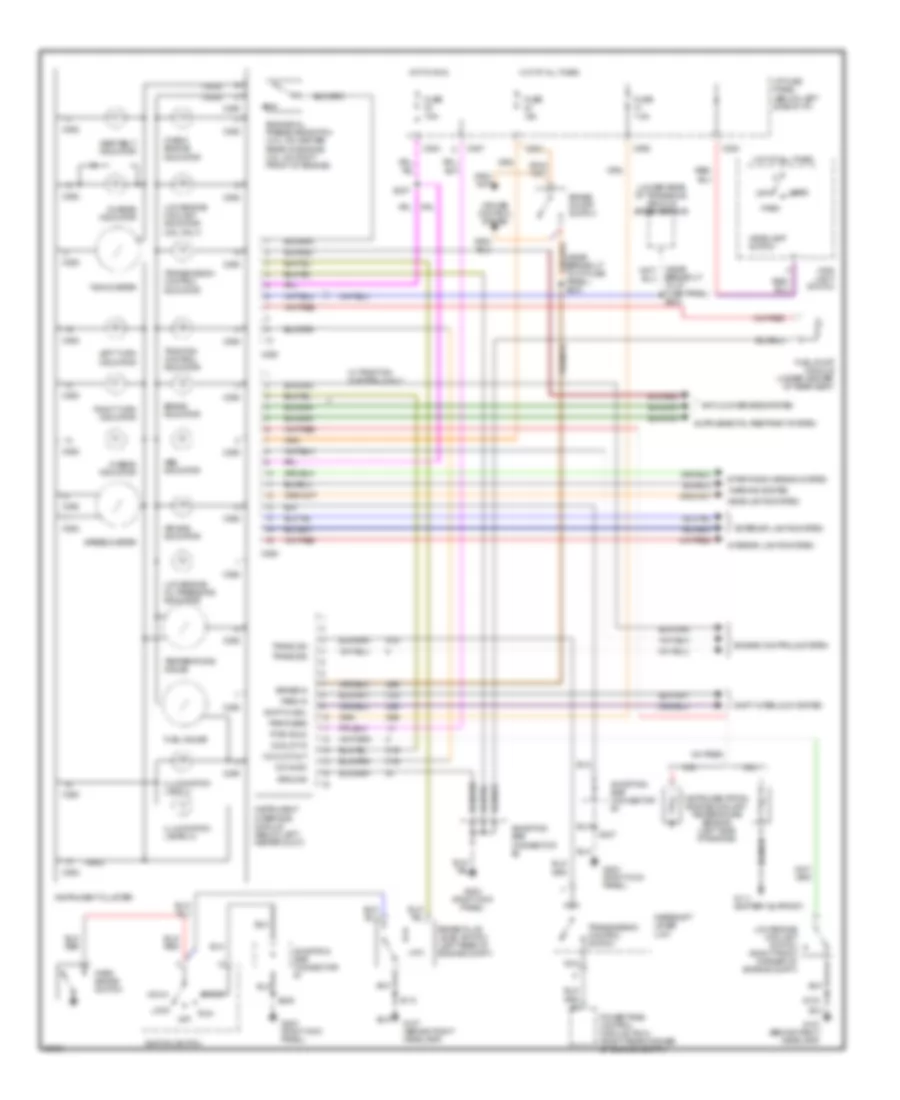
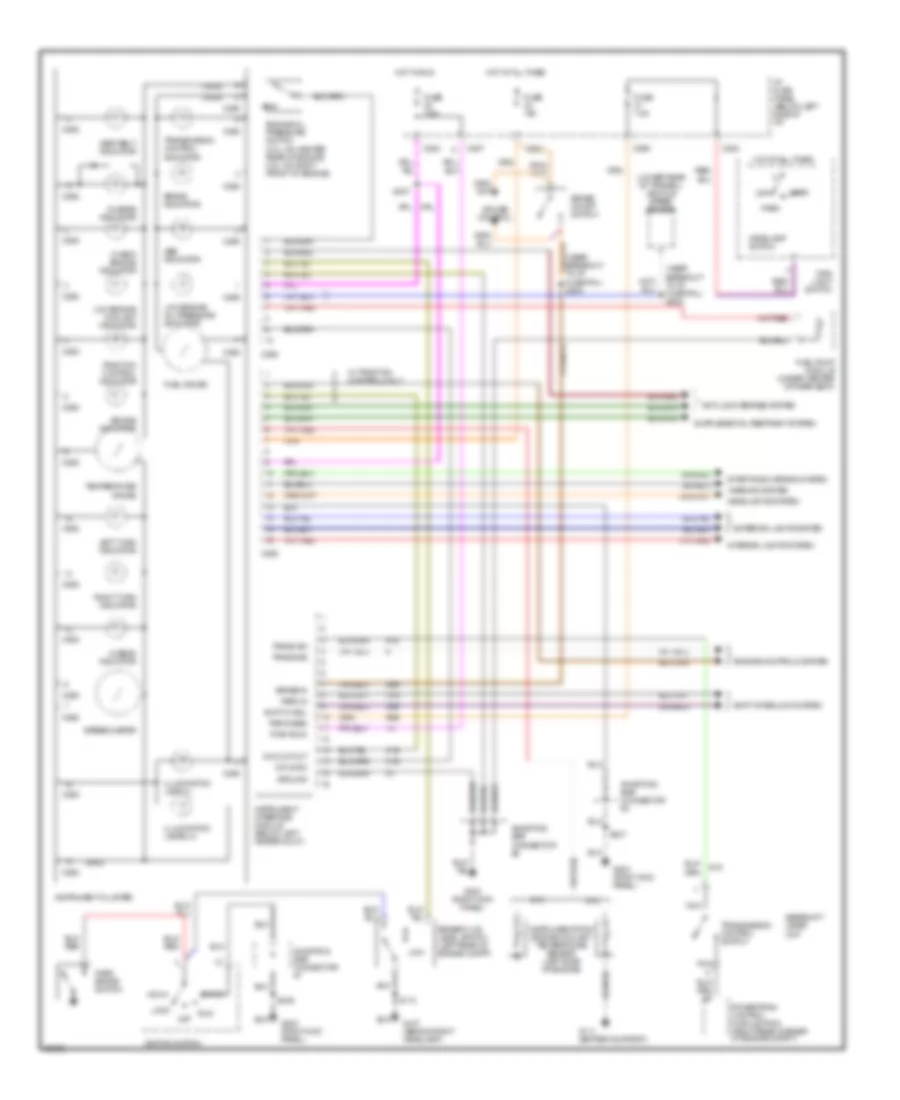
Instrument Cluster Wiring Diagram, with Tachometer for Mercury Mystique 1997
List of elements for Instrument Cluster Wiring Diagram, with Tachometer for Mercury Mystique 1997:
- (2.5l only)
- (gnd)
- (lower rear of transaxle) vehicle speed sensor
- (near breakout to i/p fuse panel) s203
- (near breakout to i/p fuse panel) s204
- (run)
- 2.0l
- 2.5l
- 29s
- 31s
- 91s
- Abs indicator
- Acc
- Air bag indicator
- Anti-lock brakes system
- Brake fluid level switch (left rear of engine compt)
- Brake in
- Brake indicator
- Brake on/off switch
- C201
- C262
- C282
- C283
- C287
- C290
- C298
- Charge indicator
- Check engine indicator
- Coolnt in
- Coolnt out
- Cruise control system
- Engine controls system
- Engine oil pressure switch (2.0l: on center rear of engine 2.5l: on right front of engine)
- Exterior lights system
- Fuel gauge
- Fuel pump module (under center of rear seat)
- Fuse 15a
- Fuse 7.5a
- G107 (behind right headlamp)
- G111 (battery support)
- G203 (right kick panel)
- Gearshift lever unit
- Ground
- Head
- Headlamp switch
- Headlights system
- Hi-beam indicator
- Hot at all times
- Hot in run
- I/p fuse panel (below left side of i/p)
- Ignition switch
- Illumination lamp (1)
- Illumination lamps (4)
- Instrument cluster
- Instrument interface module (below left heater duct)
- Instrumentation engine coolant temperature sensor (left side of engine)
- Interior lights system
- Left turn indicator
- Lock
- Low
- Low engine coolant indicator
- Low engine coolant switch (right front corner of engine compt)
- Low engine oil pressure indicator
- Main light switch
- Nca
- O/d indic
- Off
- Park
- Park brake switch
- Park in
- Park/head
- Powertrain control module (pcm) (right rear corner of engine compt.)
- Pwr (run)
- Right turn indicator
- Run
- S103
- S110
- S237
- S245
- S247
- Seat belt indicator
- Shift interlock system
- Shiftlk sol
- Shorting bar connector #1
- Shorting bar connector #2
- Shorting bar connector #3
- Speedometer
- Start
- Starting/charging system
- Tachometer
- Temperature gauge
- Traction control indicator
- Trans sig
- Trans sw
- Transmission control indicator
- Transmission control switch
- W/ traction control only
- Warning system
Instrument Cluster Wiring Diagram, without Tachometer for Mercury Mystique 1997
List of elements for Instrument Cluster Wiring Diagram, without Tachometer for Mercury Mystique 1997:
- (gnd)
- (lower rear of transxl) vehicle speed sensor
- (near breakout to i/p fuse pnl) s203
- (near breakout to i/p fuse pnl) s204
- (run)
- 2.0l
- 2.5l
- 29s
- 31s
- 91s
- Abs indicator
- Acc
- Air bag indicator
- Anti-lock brakes system
- Brake fluid level switch (left rear of engine compt)
- Brake in
- Brake indicator
- Brake on/off switch
- C201
- C262
- C282
- C283
- C287
- C290
- C298
- Charge indicator
- Check engine indicator
- Coolnt out
- Cruise control
- Engine controls system
- Engine oil pressure switch (2.0l: on center rear of engine 2.5l: on right front of engine)
- Exterior lights system
- Fuel gauge
- Fuel pump module (under center of rear seat)
- Fuse 15a
- Fuse 7.5a
- G107 (behind right headlamp)
- G111 (battery support)
- G203 (right kick panel)
- Gearshift lever unit
- Ground
- Head
- Headlamp switch
- Headlights system
- Hi-beam indicator
- Hot at all times
- Hot in run
- I/p fuse panel (below left side of i/p)
- Ignition switch
- Illumination lamp (1)
- Illumination lamps (4)
- Instrument cluster
- Instrument interface module (below left heater duct)
- Instrumentation engine coolant temperature sensor (left side of engine)
- Interior lights system
- Left turn indicator
- Lock
- Low
- Low engine coolant indicator
- Low engine oil pressure indicator
- Main light switch
- Nca
- O/d indic
- Off
- Park
- Park brake switch
- Park in
- Park/head
- Powertrain control module (pcm) (right rear corner of engine compt.)
- Pwr (run)
- Right turn indicator
- Run
- S110
- S237
- S245
- S247
- Seat belt indicator
- Shift interlock system
- Shiftlk sol
- Shorting bar connector #1
- Shorting bar connector #2
- Shorting bar connector #3
- Speedometer
- Start
- Starting/charging system
- Temperature gauge
- Traction control indicator
- Trans sig
- Trans sw
- Transmission control indicator
- Transmission control switch
- W/ traction control only
- Warning system
INTERIOR LIGHTS
Courtesy Lamps Wiring Diagram for Mercury Mystique 1997
List of elements for Courtesy Lamps Wiring Diagram for Mercury Mystique 1997:
- (inst panel harn, on inst cluster breakout) s219
- (left front rocker panel, under carpet)
- (left front rocker panel, under carpet) g309
- (not used)
- Battery
- C203
- C221
- C282
- C286
- C287
- C298
- Central timer module
- Courtesy lamps relay
- Door
- Driver door sw
- Engine compartment fuse box (left front corner of engine compartment)
- Front dome lamp
- Front dome/map lamp
- Fuse 1 80a
- Fuse 34 7.5a
- G203 (right kick panel)
- G309
- G309 (left front rocker panel, under carpet)
- G404 (left rear of trunk)
- Ground
- Hot at all times
- Illuminated entry
- Interior fuse panel (below left side of i/p)
- Key cyl illum sw
- Kick panel) s210
- Left door key cylinder lamp switch
- Left footwell lamp
- Left front door courtesy lamp switch
- Left front door under lamp
- Left front map lamp
- Left rear door courtesy lamp switch
- Left vanity mirror lamp
- Luggage compartment lamp
- Luggage compartment lamp switch
- Nca
- Off
- Pass/rear doors sw
- Power antenna module (right rear corner of luggage compartment)
- Rear dome lamp
- Rear dome/map lamp
- Red
- Remote entry module
- Remote entry module (behind right sdie of i/p)
- Right door key cylinder lamp switch
- Right footwell lamp
- Right front door courtesy lamp switch
- Right front door under lamp
- Right front map lamp
- Right rear door courtesy lamp switch
- Right vanity mirror lamp
- S208
- S209 (door lock feed harn, near air bag switch sensor breakout)
- S236
- S251
- S501
- S601
- S901
- S904
- Shorting bar connector #1
- Shorting bar connector #4
- W/ light group
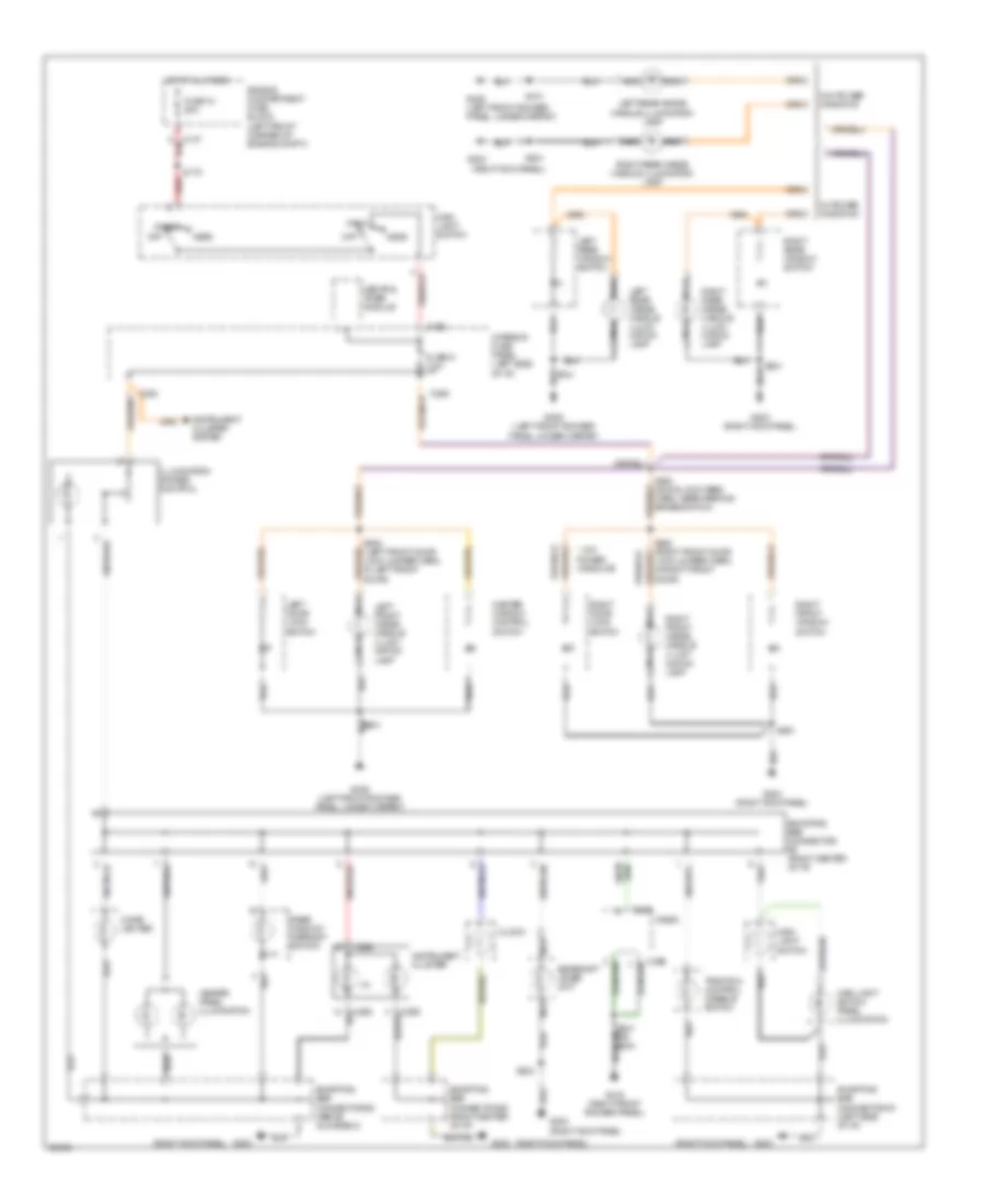
Instrument Illumination Wiring Diagram for Mercury Mystique 1997
List of elements for Instrument Illumination Wiring Diagram for Mercury Mystique 1997:
- (4)
- (right kick panel)
- * w/o power windows
- C137
- C262
- C282
- C285
- C290
- C296
- Central timer module
- Cigar lighter
- Clock
- Engine compartment fuse block (left front corner of engine compt.)
- Fuse 10 20a
- Fuse 31 7.5a
- G203
- G203 (right kick panel)
- G309 (left front rocker panel, under carpet)
- G316 (right front rocker panel)
- Gearshift lever unit
- Head
- Heater panel illumination
- Hot at all times
- Illumination dimmer control
- Instrument cluster
- Instrument cluster system
- Interior fuse panel (left side of i/p)
- Left door lock switch
- Left front inside handle illumi- nation lamp
- Left rear inside handle illumi- nation lamp
- Left rear inside handle illumination lamp
- Left rear window switch
- Main light switch
- Main light switch panel illumination
- Master window control switch
- Nca
- Off
- Park
- Radio
- Rear window defrost switch
- Red
- Right door lock switch
- Right front inside handle illumi- nation lamp
- Right front window switch
- Right rear inside handle illumi- nation lamp
- Right rear inside handle illumination lamp
- Right rear window switch
- S175
- S302
- S308 (door lock feed harn, near parking brake switch)
- S501
- S601
- S602 (right front door lock jumper harn, in right front door)
- S701
- S801
- Shorting bar connector #1 (left side of i/p)
- Shorting bar connector #2 (right center of i/p)
- Shorting bar connector #3 (above glove box)
- Shorting bar connector #5 (right center of i/p)
- Traction control disable switch
- W/ power windows
- W/o power windows
POWER ANTENNA
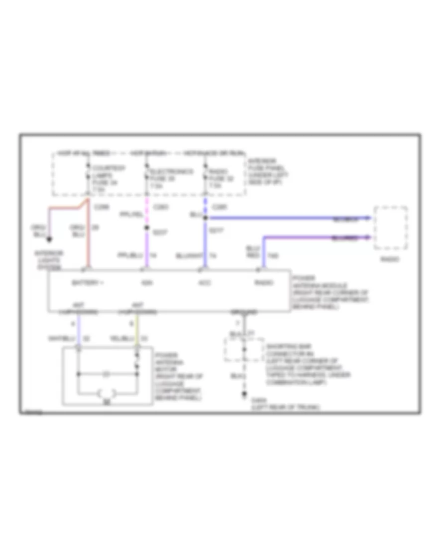
Power Antenna Wiring Diagram for Mercury Mystique 1997
List of elements for Power Antenna Wiring Diagram for Mercury Mystique 1997:
- Acc
- Ant (+up/-down)
- Ant (-up/+down)
- Battery +
- C283
- C285
- C298
- Courtesy lamps fuse 34 7.5a
- Electronics fuse 30 7.5a
- G404 (left rear of trunk)
- Ground
- Hot at all times
- Hot in acc or run
- Hot in run
- Ign
- Interior fuse panel (under left side of i/p)
- Interior lights system
- Power antenna motor (right rear of luggage compartment, behind panel)
- Power antenna module (right rear corner of luggage compartment, behind panel)
- Radio
- Radio fuse 32 7.5a
- S217
- S237
- Shorting bar connector #4 (left rear corner of luggage compartment, taped to harness, under combination lamp)
POWER DISTRIBUTION
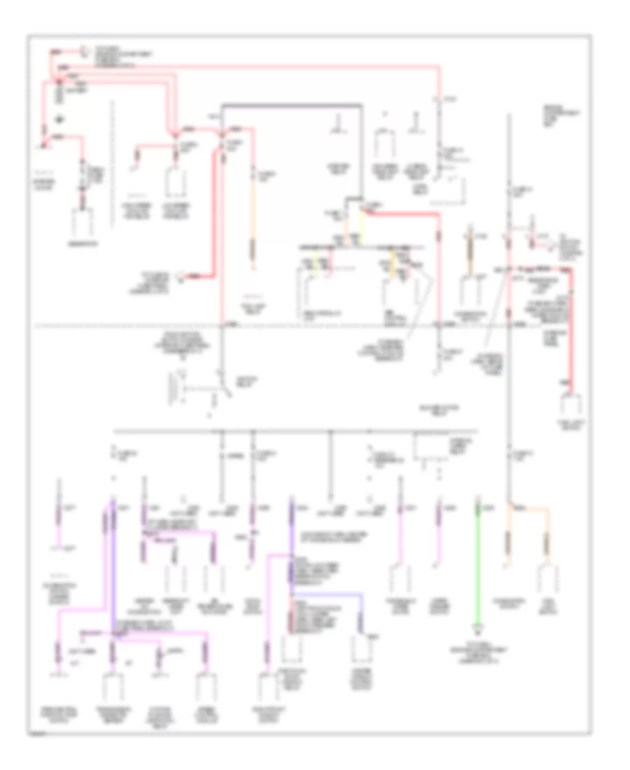
Power Distribution Wiring Diagram (1 of 3) for Mercury Mystique 1997
List of elements for Power Distribution Wiring Diagram (1 of 3) for Mercury Mystique 1997:
- (fuse box harn, above int fuse panel)
- (fuse box harn, in int fuse panel breakout) s205
- (fuse box harn, near abs control module breakout)
- (i/p harn, near inst cluster breakout) s216
- (moonroof harn, center of windshield header)
- (not used)
- 0.200
- A/t
- Abs control module
- Abs hydraulic unit
- Air temperature actuator
- Battery
- Blower motor relay
- C133
- C136
- C137
- C201
- C203
- C205
- C277
- C281
- C282
- C284
- C285
- C288
- C298
- C523
- Circuit breaker 20 10a
- Combination switch
- Combination switch (hazard switch)
- Daytime running lamps (drl) relay
- Engine compartment fuse box
- Fog lamp relay
- From ignition switch diode #2 (interior fuse panel) (diagram 3 of 3)
- Fuse 1 80a
- Fuse 10 20a
- Fuse 10 7.5a
- Fuse 12 15a
- Fuse 2 60a
- Fuse 21 40a
- Fuse 23 15a
- Fuse 3 60a
- Fuse 37 30a
- Fuse 5 15a
- Fuse 7 30a
- Gearshift lever unit
- Generator
- Heater- a/c mode switch
- High beam headlamp relay
- High speed cooling fan relay
- Horn relay
- Ignition relay
- Interior fuse panel
- Interval wiper relay
- Lo beam headlamp relay
- Low speed cooling fan relay
- M/t
- Main light switch
- Master window control switch
- Mega fuse 175a
- Moon- roof switch
- Nca
- One touch down window relay
- Park/neutral position (pnp) switch
- Red
- Resistance wire
- Right front window switch
- S173
- S175 (fuse box harn, near windshield wiper module breakout)
- S201
- S309 (door lock feed harn, near park break switch breakout)
- S503 (left front door lock jumper harn, near left front speaker breakout)
- S902
- Spare
- Speed control module
- Starter motor
- Starter relay
- To fuse 36 (interior fuse panel) (diagram 2 of 3)
- To fuse 4 (engine compartment fuse box) (diagram 2 of 3)
- To fuse 9 (engine compartment fuse box) (diagram 2 of 3)
- To ignition switch (diagram 3 of 3)
- Transmission range (tr) sensor
- W/ drl
- W/ mec iii abs
- W/o mec iii abs
- Windshield wiper motor
- Wiper/ washer switch
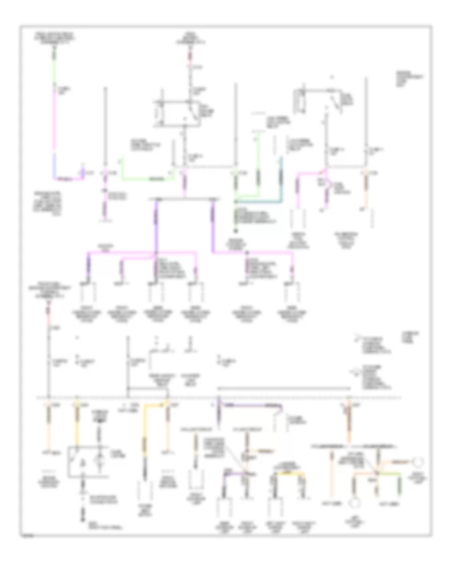
Power Distribution Wiring Diagram (2 of 3) for Mercury Mystique 1997
List of elements for Power Distribution Wiring Diagram (2 of 3) for Mercury Mystique 1997:
- (engine cntrl harn) (2.0l) (fuel shutoff harn, near ign coil breakout) (2.5l)
- (fuse box harn, near eng compt fuse box breakout)
- (i/p harn, near behind right center of i/p)
- (moonfoof harn, near moonroof motor breakout)
- (not used)
- 2.0l
- 2.5l
- A/c wide open throttle (wot) relay
- Air bag diagnostic monitor
- C133
- C136
- C137
- C203
- C205
- C234
- C284
- C285
- C287
- C298
- Cigar lighter
- Courtesy lamp relay
- Engine compartment fuse box
- Engine controls system
- From battery (diagram 1 of 3)
- From fuse 1 (engine compartment fuse box) (diagram 1 of 3)
- From ignition relay (interior fuse panel) (diagram 1 of 3)
- Front dome/map lamp
- Front heated oxygen sensor #11 (ho2s)
- Front heated oxygen sensor #21 (ho2s)
- Front remote amplifier
- Fuel pump monitor
- Fuel pump relay
- Fuse 11 3a
- Fuse 13 15a
- Fuse 14 15a
- Fuse 27 15a
- Fuse 28 30a
- Fuse 34 7.5a
- Fuse 36 10a
- Fuse 4 20a
- Fuse 9 20a
- G203 (right kick panel)
- High speed cooling fan relay
- Ignition coil
- Inertia fuel shutoff (ifs) switch
- Interior fuse panel
- Interior lights system
- Left footwell lamp
- Left vanity mirror lamp
- Low speed cooling fan relay
- Luggage compartment lamp
- Nca
- Pcm power relay
- Power antenna
- Power seat switch
- Powertrain control module (pcm)
- Rear dome/map lamp
- Rear heated oxygen sensor #12 (ho2s)
- Rear heated oxygen sensor #22 (ho2s)
- Rear window defrost relay
- Red
- Right footwell lamp
- Right vanity mirror lamp
- S153 (2.0l) s132 (2.5l)
- S164 (engine cntrl harn, left side of eng compartment)
- S236
- S251
- S904
- Shorting bar connector #3
- To fuse 25 (interior fuse panel) (diagram 3 of 3)
- To power mirror switch (interior fuse panel) (diagram 3 of 3)
- W/o light group
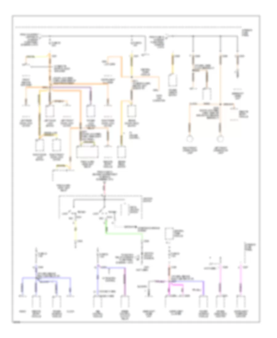
Power Distribution Wiring Diagram (3 of 3) for Mercury Mystique 1997
List of elements for Power Distribution Wiring Diagram (3 of 3) for Mercury Mystique 1997:
- (door lock feed harn, near rear of right front seat)
- (i/p harn, behind right center of i/p) s217
- (i/p harn, behind right center of i/p) s237
- (i/p harn, near clock breakout) s222
- (not used)
- (w/ mec iii abs)
- (w/o mec iii abs)
- Abs control module
- Acc
- Air bag diagnostic monitor
- Brake on/off (boo) switch
- Brake pedal switch
- C201
- C234
- C262
- C281
- C282
- C283
- C285
- C286
- C287
- C288
- C290
- Central timer module
- Clock
- Data link connctor
- From courtesy lamp relay f (interior fuse panel) (diagram 2 of 3)
- From fuse 10 (engine compartment fuse box) (diagram 1 of 3)
- From fuse 34 g (interior fuse panel) (diagram 2 of 3)
- Front remote amplifier
- Fuse 22 7.5a
- Fuse 24 15a
- Fuse 25 20a
- Fuse 30 7.5a
- Fuse 32 7.5a
- Gear shift lever unit
- Gearshift lever unit
- Ignition switch
- Ignition switch diode #2
- Instrument cluster
- Instrument interface monitor
- Interior fuse panel
- Key in ignition switch
- Left door lock switch
- Left front door lock motor
- Left front under door lamp
- Left rear door lock motor
- Lock
- Nca
- Panic alarm headlamp relay
- Panic alarm stop lamp relay
- Power antenna module
- Power lock control relay
- Power mirror switch
- Radio
- Red
- Remote entry module
- Right door lock switch
- Right front door lock motor
- Right front under door lamp
- Right rear door lock motor
- Run
- S207 (door lock feed harn, near right kick panel)
- S208 (door lock feed harn, near air bag switch sensor breakout)
- S211 (fuse box harn, behind left side of i/p)
- S304
- Speed control cut-out relay
- Start
- Starting/charging system
- To ignition relay (interior fuse panel) (diagram 1 of 3)
- W/ cruise control
- W/ remote entry & audi0 amplifier
- W/ traction control
POWER DOOR LOCKS
Door Lock Wiring Diagram for Mercury Mystique 1997
List of elements for Door Lock Wiring Diagram for Mercury Mystique 1997:
- (door lock harn, behind shield, near rear of right front seat bottom) s303
- (door lock harn, behind shield, near rear of right front seat bottom) s305
- C281
- Fuse 20a
- G203 (right kick panel)
- G309 (left front rocker panel, under carpet)
- Hot at all times
- Interior fuse panel (left side of i/p)
- Interior lights system
- Left door lock switch
- Left front door lock motor
- Left rear door lock motor
- Lock
- Power lock control relay (behind top of right kick panel)
- Right door lock switch
- Right front door lock motor
- Right rear door lock motor
- S302
- S304
- S306
- S501
- S601
- S701
- S801
- Solid state
- Unlock
- W/ power windows
Keyless Entry Wiring Diagram for Mercury Mystique 1997
List of elements for Keyless Entry Wiring Diagram for Mercury Mystique 1997:
- (door lock harn, behind shield, near rear of right front seat bottom)
- (door lock harn, behind shield, near rear of right front seat bottom) s303
- (door lock harn, near breakout to g203) s207
- 29s
- 31s
- All lock
- All unlock
- C221
- C222
- C281
- C285
- C286
- C287
- Central timer module (left side of i/p, on fuse panel)
- Computer data lines system
- Decklid motor (center rear of luggage compt)
- Diagnostic
- Exterior lights system
- Fuse 20a
- Fuse 7.5a
- G203 (right kick panel)
- G309 (left front rocker panel, under carpet)
- G404 (left rear of trunk)
- Ground
- Headlights system
- Horn relay
- Horns system
- Hot at all times
- Hot in acc or run
- Hot in run
- Interior fuse panel (left side of i/p)
- Interior lights system
- Left door lock switch
- Left front door lock motor
- Left rear door lock motor
- Lf unlock
- Lock
- Off
- Panic
- Panic alarm headlamp relay (under right side of i/p, behind right side of glove box)
- Panic alarm stoplamp relay (under right side of i/p, behind right side of glove box)
- Power
- Remote entry module (under right side of i/p, behind right side of glove box)
- Right door lock switch
- Right front door lock motor
- Right rear door lock motor
- S208
- S217
- S302
- S304
- S305
- S306
- S501
- S601
- S701
- S801
- Shorting bar connector #4 (left rear corner of luggage compt, taped to harness, under comb. lamp)
- Timer
- Trnk rlse
- Unlck
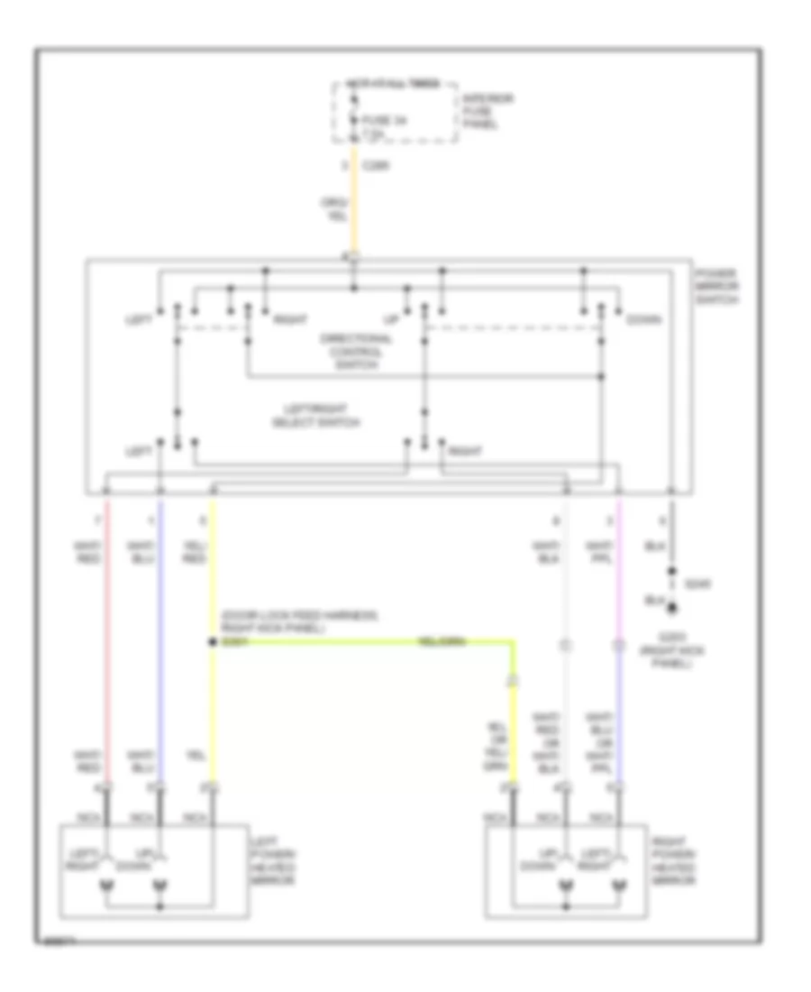
POWER MIRRORS
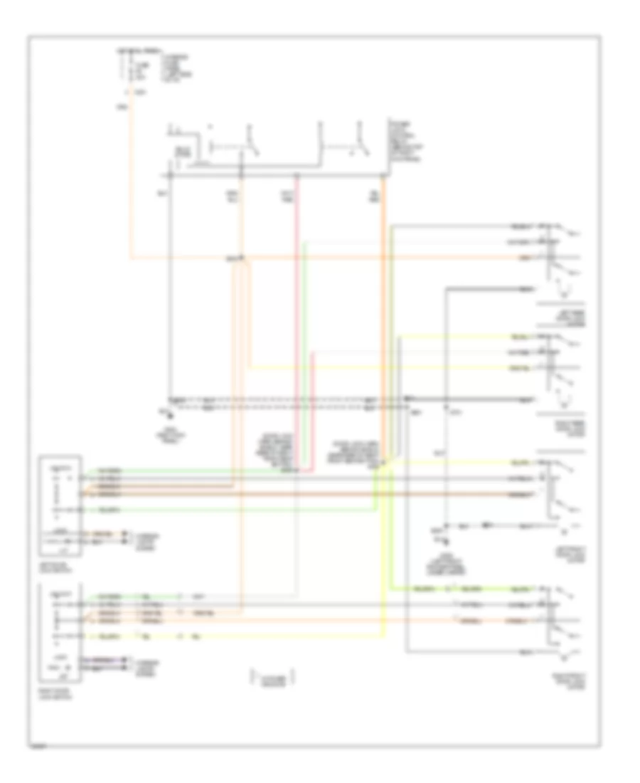
Power Mirror Wiring Diagram for Mercury Mystique 1997
List of elements for Power Mirror Wiring Diagram for Mercury Mystique 1997:
- (door lock feed harness, right kick panel) s301
- C286
- Directional control switch
- Down
- Fuse 34 7.5a
- G203 (right kick panel)
- Hot at all times
- Interior fuse panel
- Left
- Left power/ heated mirror
- Left/ right
- Left/right select switch
- Nca
- Power mirror switch
- Right
- Right power/ heated mirror
- S245
- Up/ down
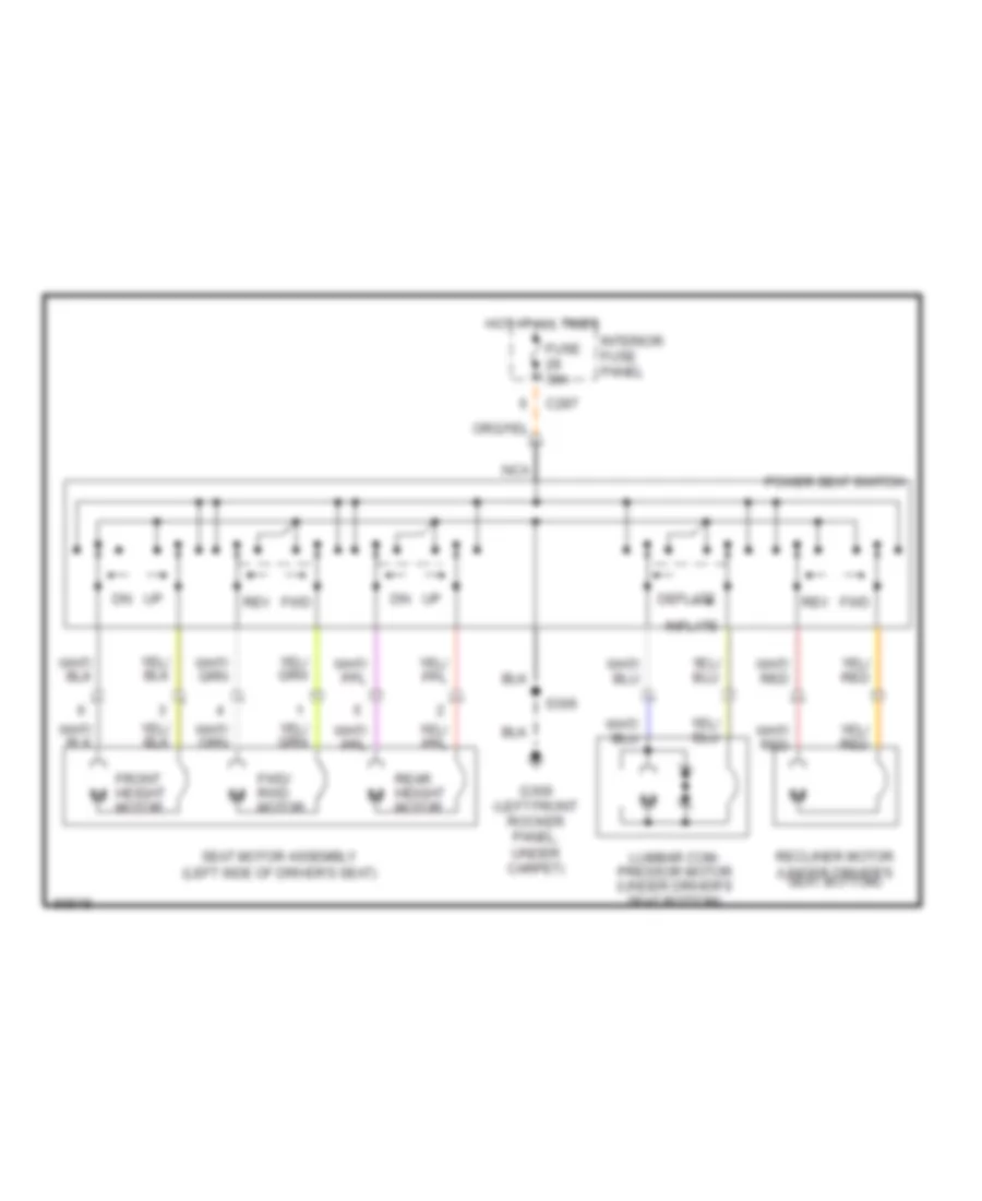
POWER SEATS
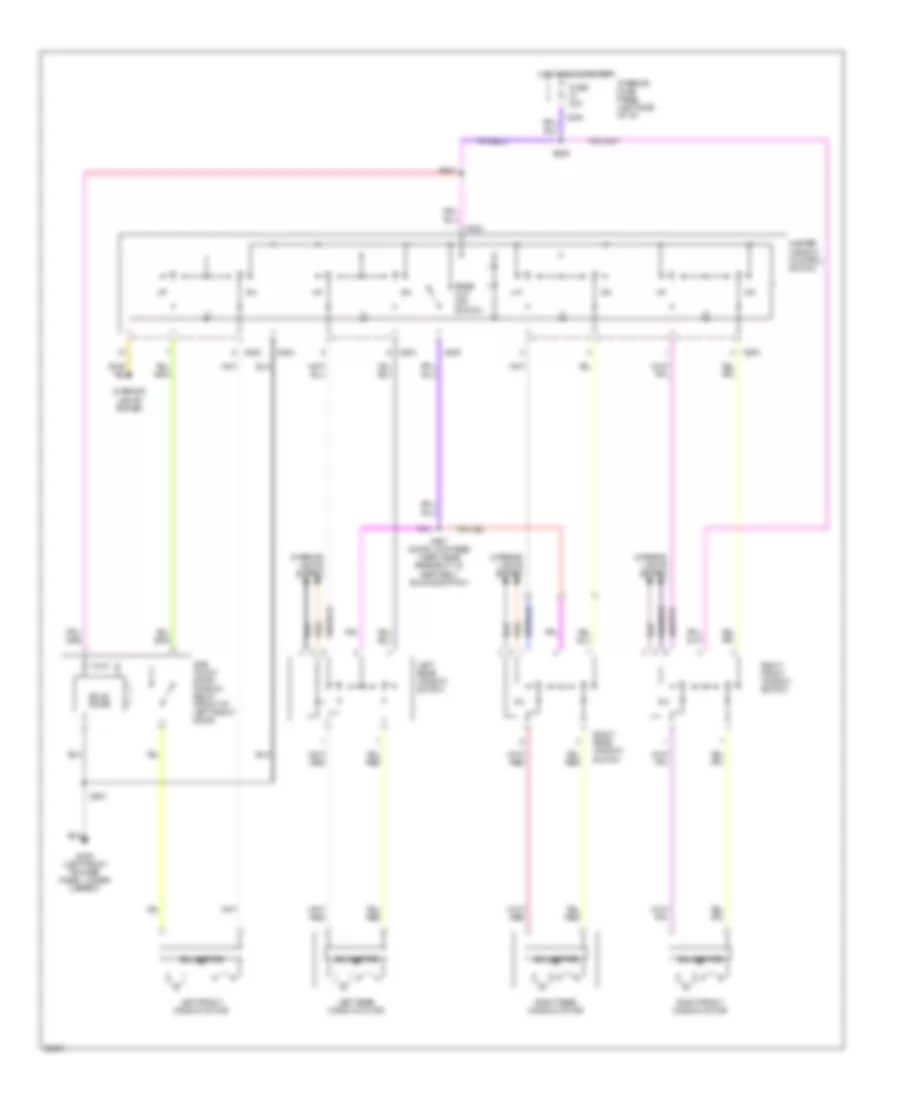
6-Way, Recliner & Lumbar Power Seat Wiring Diagram for Mercury Mystique 1997
List of elements for 6-Way, Recliner & Lumbar Power Seat Wiring Diagram for Mercury Mystique 1997:
- C287
- Deflate
- Front height motor
- Fuse 30a
- Fwd
- Fwd/ rwd motor
- G309 (left front rocker panel, under carpet)
- Hot at all times
- Inflate
- Interior fuse panel
- Lumbar com- pressor motor (under driver's seat bottom)
- Nca
- Power seat switch
- Rear height motor
- Recliner motor (under driver's seat bottom)
- Rev
- S306
- Seat motor assembly (left side of driver's seat)
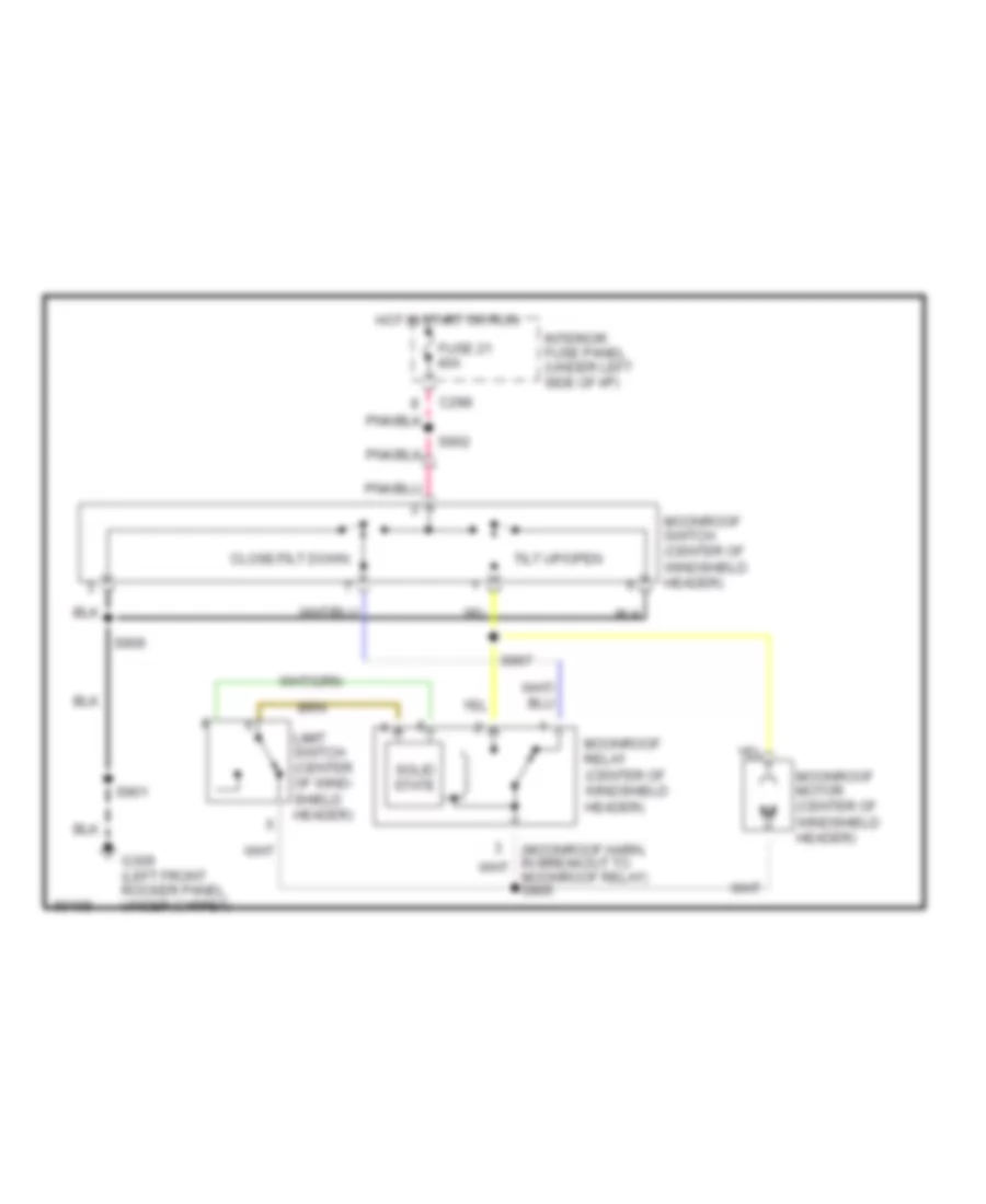
POWER TOP/SUNROOF
Power Top/Sunroof Wiring Diagrams for Mercury Mystique 1997
List of elements for Power Top/Sunroof Wiring Diagrams for Mercury Mystique 1997:
- C298
- Close/tilt down
- Fuse 21 40a
- G309 (left front rocker panel, under carpet)
- Hot in start or run
- Interior fuse panel (under left side of i/p)
- Limit switch (center of wind- shield header)
- Moonroof motor (center of windshield header)
- Moonroof relay (center of windshield header)
- Moonroof switch (center of windshield header)
- S901
- S902
- S906
- S907
- Solid state
- Tilt up/open
POWER WINDOWS
Power Window Wiring Diagram for Mercury Mystique 1997
List of elements for Power Window Wiring Diagram for Mercury Mystique 1997:
- C284
- C503
- C523
- Fuse 40a
- G309 (left front rocker panel, under carpet)
- Hot in run or start
- Interior fuse panel (left side of i/p)
- Interior lights system
- Left front window motor
- Left rear window motor
- Left rear window switch
- Master window control switch
- One touch down window relay (front of left front door)
- Rear cut off switch
- Right front window motor
- Right front window switch
- Right rear window motor
- Right rear window switch
- S307 (door lock feed harn, near breakout to seat belt buckle switch)
- S309
- S501
- S503
- Solid state
RADIO
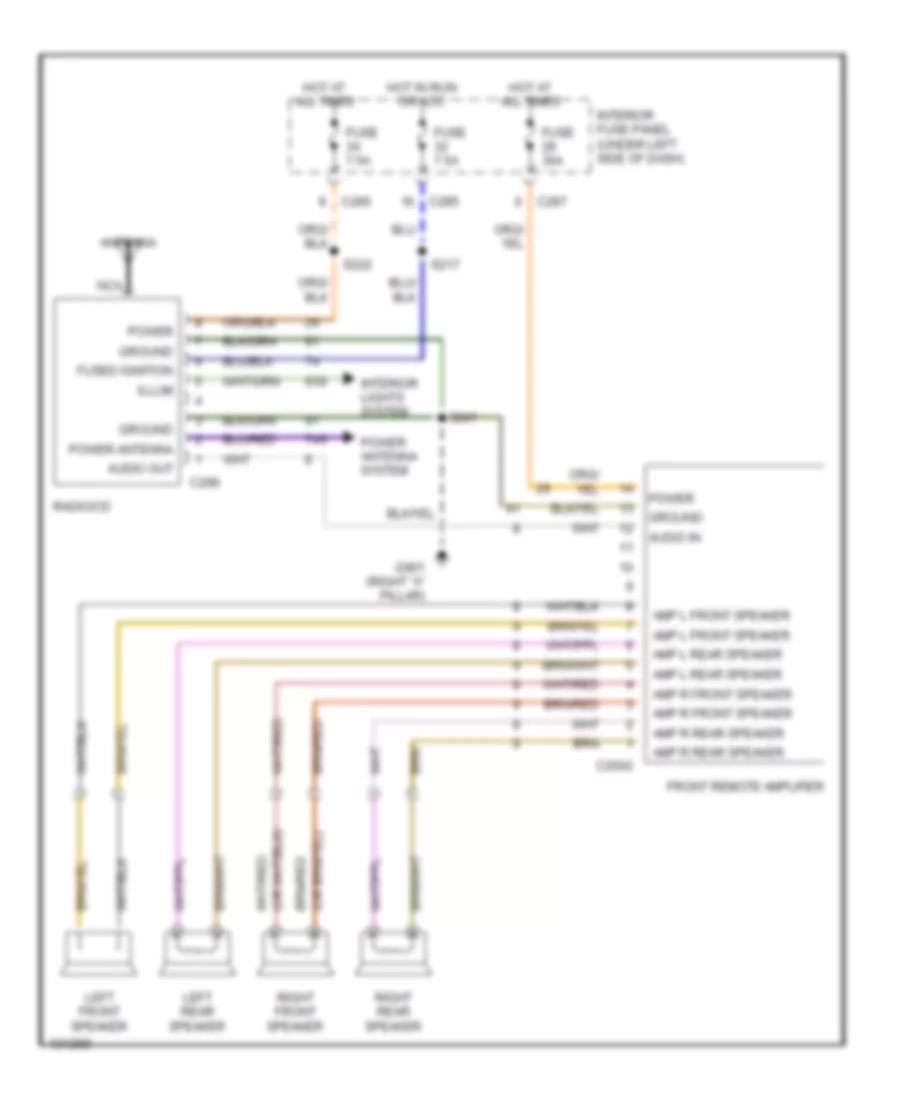
Radio Wiring Diagrams, with Amplifier for Mercury Mystique 1997
List of elements for Radio Wiring Diagrams, with Amplifier for Mercury Mystique 1997:
- 63s
- 74s
- Amp l front speaker
- Amp l rear speaker
- Amp r front speaker
- Amp r rear speaker
- Antenna
- Audio in
- Audio out
- C2002
- C285
- C287
- C296
- Front remote amplifier
- Fuse 30a
- Fuse 7.5a
- Fused ignition
- G901 (right "a" pillar)
- Ground
- Hot at all times
- Hot in run or acc
- Illum
- Interior fuse panel (under left side of dash)
- Interior lights system
- Left front speaker
- Left rear speaker
- Nca
- Power
- Power antenna
- Power antenna system
- Radio/cd
- Right front speaker
- Right rear speaker
- S217
- S222
- S241
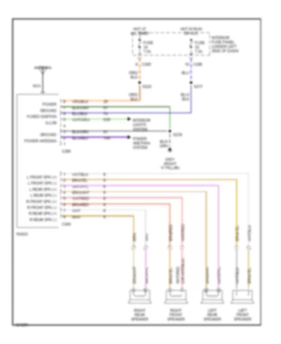
Radio Wiring Diagrams, without Amplifier for Mercury Mystique 1997
List of elements for Radio Wiring Diagrams, without Amplifier for Mercury Mystique 1997:
- 63s
- 74s
- Antenna
- C240
- C285
- C296
- Fuse 7.5a
- Fused ignition
- G901 (right "a" pillar)
- Ground
- Hot at all times
- Hot in run or acc
- Illum
- Interior fuse panel (under left side of dash)
- Interior lights system
- L front spk (+)
- L front spk (-)
- L rear spk (+)
- L rear spk (-)
- Left front speaker
- Left rear speaker
- Nca
- Power
- Power anetnna system
- Power antenna
- R front spk (+)
- R front spk (-)
- R rear spk (+)
- R rear spk (-)
- Radio
- Right front speaker
- Right rear speaker
- S217
- S222
- S239
SHIFT INTERLOCKS
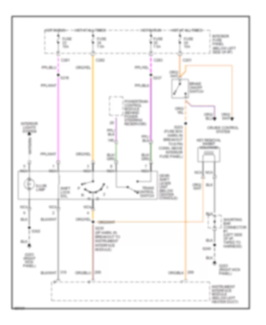
Shift Interlock Wiring Diagram for Mercury Mystique 1997
List of elements for Shift Interlock Wiring Diagram for Mercury Mystique 1997:
- 14s
- Brake on/off switch
- C201
- C281
- C282
- C283
- Cruise control system
- Fuse 15a
- Fuse 7.5a
- G203 (right kick panel)
- Gear- shift lever unit (below center console)
- Hot at all times
- Hot in run
- Illum. lamp
- Instrument interface module (below left heater duct)
- Interior fuse panel (below left side of i/p)
- Interior lights system
- Key removal inhibit solenoid
- Nca
- Powertrain control module (behind power steering reservoir)
- S203 (fuse box harn, in breakout to 8 pin conn, above interior fuse panel)
- S216
- S235 (i/p harn, in breakout to instrument interface module)
- S237
- S245
- S302
- Shift lock sol.
- Shorting bar connector #1 (left side of i/p, taped to harness)
- Trans control switch
STARTING/CHARGING
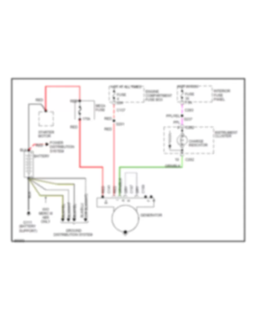
Charging Wiring Diagram for Mercury Mystique 1997
List of elements for Charging Wiring Diagram for Mercury Mystique 1997:
- (battery support)
- 175a
- Battery
- C137
- C141
- C187
- C189
- C262
- C283
- Charge indicator
- Engine compartment fuse box
- Fuse 20a
- Fuse 7.5a
- G111
- Generator
- Ground distribution system
- Hot at all times
- Hot in run
- Instrument cluster
- Interior fuse panel
- Mega fuse
- Power distribution system
- Red
- S201
- S237
- Starter motor
- W/o merc iii abs only
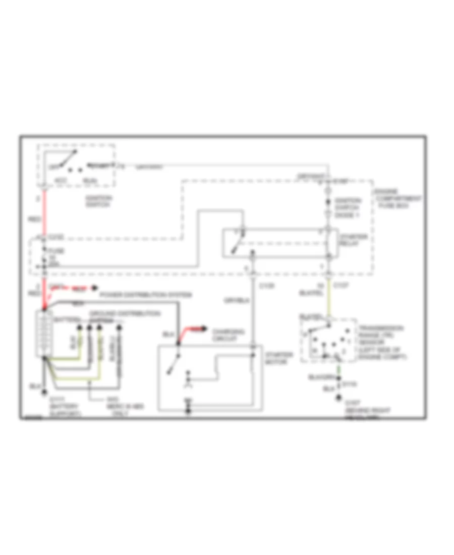
Starting Wiring Diagram, A/T for Mercury Mystique 1997
List of elements for Starting Wiring Diagram, A/T for Mercury Mystique 1997:
- Acc
- Battery
- C133
- C135
- C137
- Charging circuit
- Compartment
- Engine
- Fuse 20a
- Fuse box
- G107 (behind right headlamp)
- G111 (battery support)
- Ground distribution system
- Ignition switch
- Ignition switch diode 1
- Off
- Only
- Power distribution system
- Red
- Run
- S110
- Start
- Starter motor
- Starter relay
- Transmission range (tr) sensor (left side of engine compt)
- W/o merc iii abs
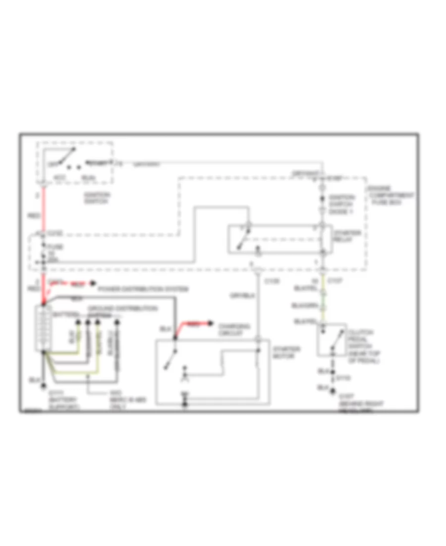
Starting Wiring Diagram, M/T for Mercury Mystique 1997
List of elements for Starting Wiring Diagram, M/T for Mercury Mystique 1997:
- Acc
- Battery
- C133
- C135
- C137
- Charging circuit
- Clutch pedal switch (near top of pedal)
- Compartment
- Engine
- Fuse 20a
- Fuse box
- G107 (behind right headlamp)
- G111 (battery support)
- Ground distribution system
- Ignition switch
- Ignition switch diode 1
- Off
- Power distribution system
- Red
- Run
- S110
- Start
- Starter motor
- Starter relay
- W/o merc iii abs only
SUPPLEMENTAL RESTRAINTS
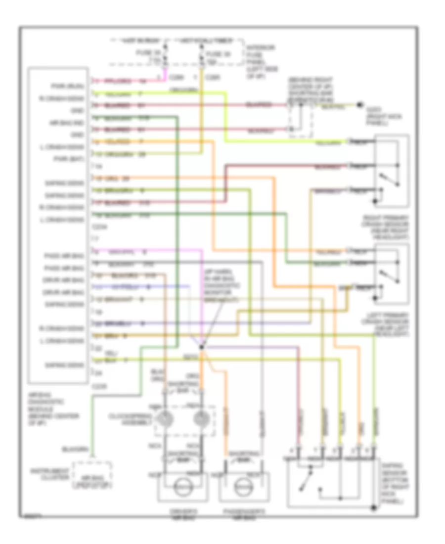
Supplemental Restraint Wiring Diagram for Mercury Mystique 1997
List of elements for Supplemental Restraint Wiring Diagram for Mercury Mystique 1997:
- (behind right center of i/p) shorting bar connector #2
- (i/p harn, in air bag diagnostic monitor breakout)
- 31s
- Air bag diagnostic module (behind center of i/p)
- Air bag ind
- Air bag indicator
- C234
- C235
- C285
- C286
- Clockspring assembly
- Cluster
- Driver's air bag
- Drvr air bag
- Fuse 30 7.5a
- Fuse 36 10a
- G203 (right kick panel)
- Gnd
- Hot at all times
- Hot in run
- Instrument
- Interior fuse panel (left side of i/p)
- L crash sens
- Left primary crash sensor (near left headlight)
- Nca
- Pass air bag
- Passenger's air bag
- Pwr (bat)
- Pwr (run)
- R crash sens
- Right primary crash sensor (near right headlight)
- S213
- Safing sens
- Safing sensor (bottom of right kick panel)
- Shorting bar
TRANSMISSION
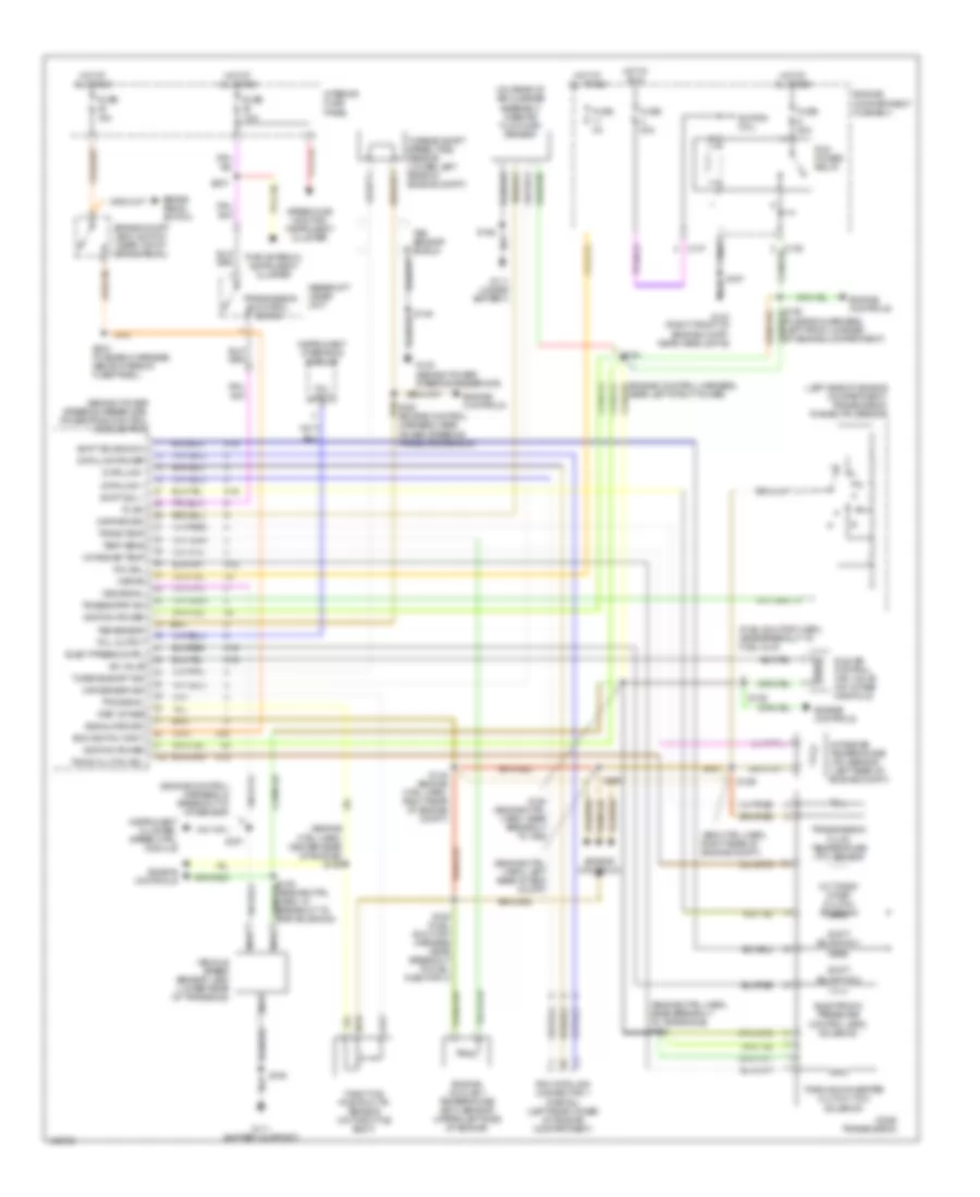
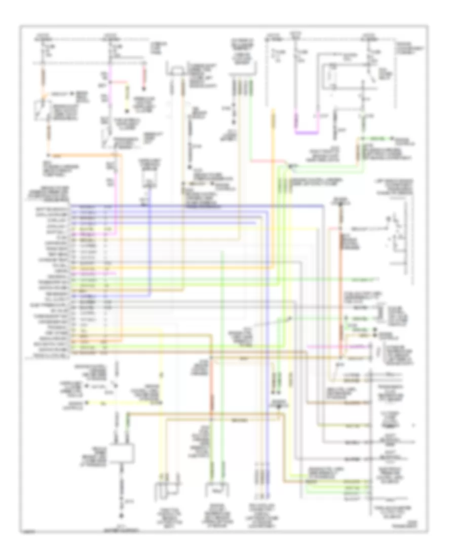
2.0L
2.0L, Transmission Wiring Diagram for Mercury Mystique 1997
List of elements for 2.0L, Transmission Wiring Diagram for Mercury Mystique 1997:
- (behind power steering reservoir) powertrain control module (pcm)
- (eng ctrl harn, right rear of engine compt)
- (engine control harness, in breakout to iat sensor)
- (engine ctrl harn, center rear of engine) s150
- (engine ctrl harn, left rear of eng compt)
- (engine ctrl harn, near breakout to transaxle) s133
- (fuel shutoff harn, near breakout to fuel inj 5)
- (fuse box harness, left front corner of engine compartment)
- (left side of engine compartment) transmission range (tr) sensor
- (on rear of air cleaner assembly) mass air flow (maf) sensor
- 29s
- 3-2 timing/ coast clutch solenoid
- 91s
- Airbag diag monitor, instrument cluster
- Boo switch input
- Brake on/off (boo) switch (near top of brake pedal)
- Brake pedal switch
- C137
- Cd4e transmission
- Data link +
- Data link -
- Data link power
- Elect press cntrl
- Electronic pressure control (epc) solenoid
- Engine compartment fuse box
- Engine controls
- Engine coolant temperature (ect) sensor (upper left side of engine)
- Fuse 15a
- Fuse 20a
- Fuse 3a
- Fuse 7.5a
- G107 (right front of engine compt, near headlights)
- G111 (battery support)
- G111 (under battery)
- G123 (behind power steering reservoir)
- Gearshift lever unit
- Hot at all times
- Hot in run
- Iac valve
- Idle air control (iac) valve (on intake manifold)
- Ignition power
- Igntion coil
- Instrument cluster, speed ctrl module
- Instrument interface module
- Intake air temp
- Intake air temperature (iat) sensor (left rear of engine compt)
- Interior fuse panel
- Kapwr
- Maf return
- Maf sensor sig
- Nca
- Pcm data link connector 1 (partial) (left rear coner of engine compartment)
- Pcm power relay
- Pwr antenna, instrument cluster
- Ref votage
- S107
- S128 (fuel shut-off harness near breakout to fuel injector 3)
- S129
- S148 (engine ctrl harn, right rear of engine compt)
- S154 (engine ctrl harn, near breakout to vss)
- S156
- S157
- S158
- S159
- S161
- S203 (fuse box harness, above interior fuse panel)
- S237
- Shift sol 1
- Shift solenoid 1
- Shift solenoid 2
- Signal return
- Tc sw
- Tcc sol
- Tcil input
- Tcil output
- Temp sens
- Throttle position (tp) sensor (on throttle body)
- Timing clutch sol
- Torque converter clutch (tcc) solenoid
- Tps signal
- Tr sens/pnp sw
- Trans temp
- Transmission control switch
- Transmission fluid temperature (tft) sensor
- Tss sensor
- Tss sensor shield
- Turbine shaft sig
- Turbine shaft speed (tss) sensor (lower left rear of engine compt)
- Vehicle speed sensor (vss) (lower rear of transaxle)
- Vss signal
2.5L
2.5L, Transmission Wiring Diagram for Mercury Mystique 1997
List of elements for 2.5L, Transmission Wiring Diagram for Mercury Mystique 1997:
- (behind power steering reservoir) powertrain control module (pcm)
- (eng ctrl harn, center rear of engine)
- (engine control harn, center rear of engine) s143
- (engine control harness, center rear of engine)
- (engine ctrl harn, near breakout to transaxle) s133
- (fuel shutoff harn, near breakout to fuel inj 5)
- (fuse box harness, left front corner of engine compartment)
- (left side of engine compartment) transmission range (tr) sensor
- (on rear of air cleaner assembly)
- 29s
- 3-2 timing/ coast clutch solenoid
- 91s
- Airbag diag monitor, instrument cluster
- Boo switch input
- Brake on/off (boo) switch (near top of brake pedal)
- Brake pedal switch
- C137
- Cd4e transmission
- Data link +
- Data link -
- Data link power
- Elect press cntrl
- Electronic pressure control (epc) solenoid
- Engine compartment fuse box
- Engine controls
- Engine coolant temperature (ect) sensor (upper left side of engine)
- Fuse 15a
- Fuse 20a
- Fuse 3a
- Fuse 7.5a
- G107 (right front of engine compt, near headlights)
- G111 (battery support)
- G111 (under battery)
- G123 (behind power steering reservoir)
- Gearshift lever unit
- Hot at all times
- Hot in run
- Iac valve
- Idle air control (iac) valve (on intake manifold)
- Ignition power
- Igntion coil
- Instrument cluster, speed ctrl module
- Instrument interface module
- Intake air temp
- Intake air temperature (iat) sensor (left rear of engine compt)
- Interior fuse panel
- Kapwr
- Maf return
- Maf sensor sig
- Mass air flow (maf) sensor
- Nca
- Pcm data link connector 1 (partial) (left rear coner of engine compartment)
- Pcm power relay
- Pwr antenna, instrument cluster
- Ref votage
- S119
- S128 (fuel shut-off harness near breakout to fuel injector 3)
- S129
- S141 (engine ctrl harn, near breakout to vss)
- S142
- S144
- S158
- S161
- S168 (engine control harness)
- S203 (fuse box harness, above interior fuse panel)
- S237
- Shift sol 1
- Shift solenoid 1
- Shift solenoid 2
- Signal return
- Tc sw
- Tcc sol
- Tcil input
- Tcil output
- Temp sens
- Throttle position (tp) sensor (on throttle body)
- Timing clutch sol
- Torque converter clutch (tcc) solenoid
- Tps signal
- Tr sens/pnp sw
- Trans temp
- Transmission control switch
- Transmission fluid temperature (tft) sensor
- Tss sensor
- Tss sensor shield
- Turbine shaft sig
- Turbine shaft speed (tss) sensor (lower left rear of engine compt)
- Vehicle speed sensor (vss) (lower rear of transaxle)
- Vss signal
WARNING SYSTEMS
Warning System Wiring Diagrams for Mercury Mystique 1997
List of elements for Warning System Wiring Diagrams for Mercury Mystique 1997:
- Acc
- C201
- C203
- C262
- C279
- C282
- C283
- C285
- C287
- C288
- Central timer module
- Courtesy lamp relay
- Defogger system
- Defrost refrost
- Defrost sw
- Door locks system
- Driver door sw
- Engine compartment fuse box (left front corner of engine compartment)
- Fuse 30 7.5a
- G203 (right kick panel)
- G309 (left front rocker panel, under carpet)
- Ground
- Head
- Headlamp switch
- Hot at all times
- Hot in run
- Ignition sw
- Ignition switch
- Illum entry
- Instrument cluster
- Inter wiper sw
- Interior fuse panel (below left side of i/p)
- Interior lights system (illuminated entry)
- Interval wiper relay
- Key illum sw
- Key in ign sw
- Key in ignition switch
- Left front door courtesy lamp switch
- Left rear door courtesy lamp switch
- Lock
- Main fuse 80a
- Main light switch
- Off
- Park
- Park lamp sw
- Pass/rear doors sw
- Power (bat)
- Rear window defrost relay
- Red
- Remote entry mod in
- Right front door courtesy lamp switch
- Right rear door courtesy lamp switch
- Run
- S237
- S245
- S306
- Seat belt buckle sw
- Seat belt buckle switch
- Seat belt indicator
- Seat belt warn ind
- Shorting bar connector #1 (left side of steering column taped to harness)
- Start
- Washer sw
- Wiper park
- Wiper/rate select
- Wiper/washer system
WIPER/WASHER
Wiper/Washer Wiring Diagram for Mercury Mystique 1997
List of elements for Wiper/Washer Wiring Diagram for Mercury Mystique 1997:
- C201
- C228
- Central timer module
- G107 (right front of engine compt, near head lamps)
- G203 (below right kick panel)
- Hot at all times
- Hot in run
- Ignition relay
- Ignition switch
- Int
- Interior fuse panel
- Interval wiper relay
- Mist
- Mystique only
- Off
- S110
- S245
- Shorting bar connector 1 (under left side of i/p)
- Variable interval sw
- Washer switch
- Windshield washer motor
- Windshield wiper motor
- Wiper switch
- Wiper/ washer switch
- Wipers circuit breaker 20 10a

 Čeština
 Dansk
Dansk Deutsch
 Ελληνικά
 English
 English
 Suomi
Suomi Français
 Français
 עברית
עברית Hrvatski
 Magyar
 Italiano
 日本語
日本語 한국어
한국어 Nederlands
 Polski
 Português
 Português
 Română
 Русский
 Slovenčina
 Slovenščina
 Svenska
 Türkçe
 中文 (中国)