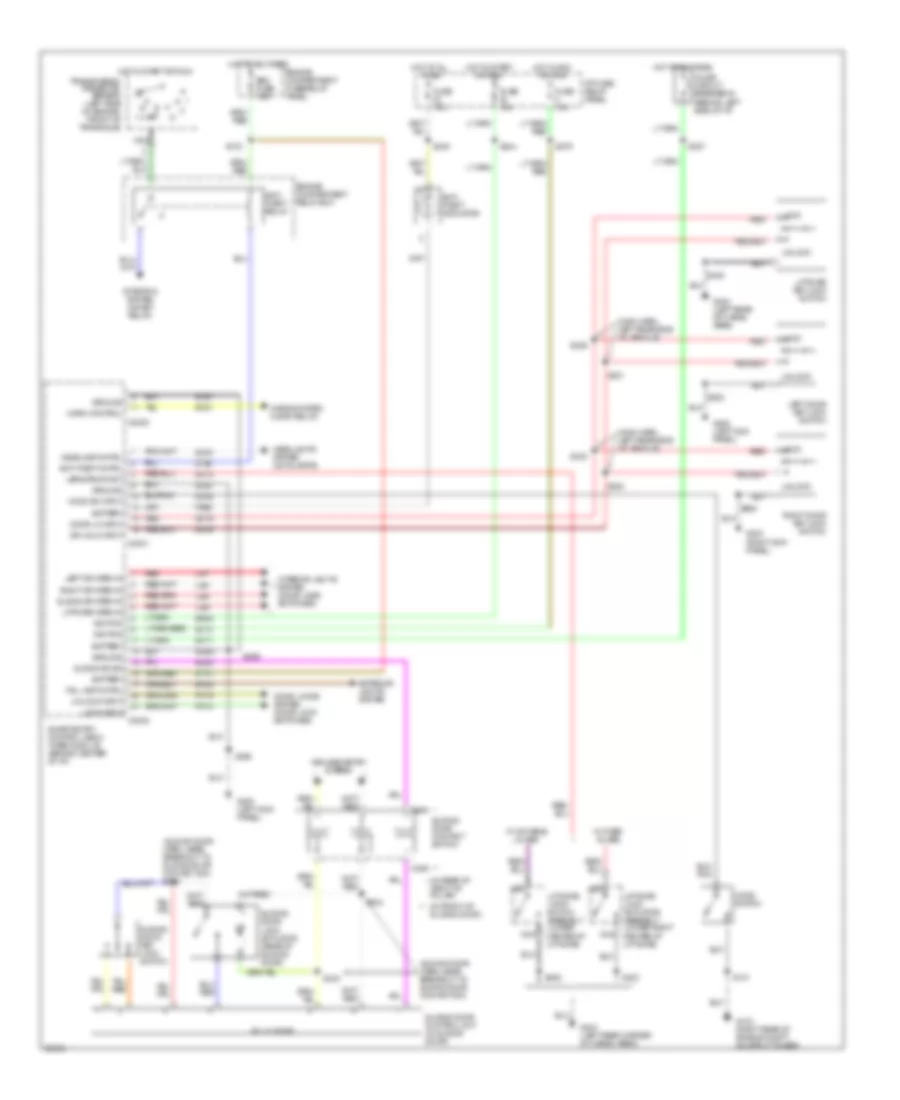
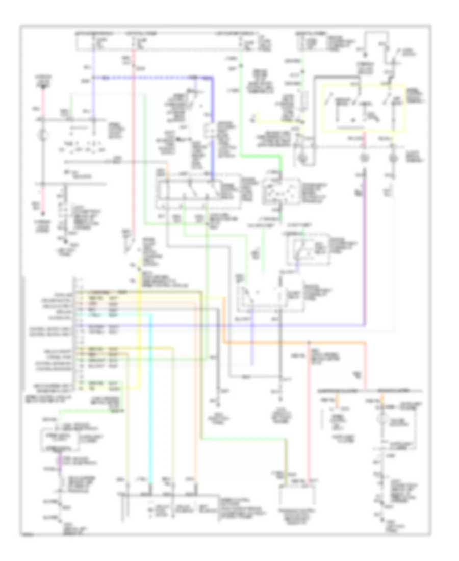
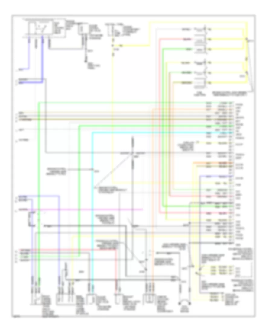
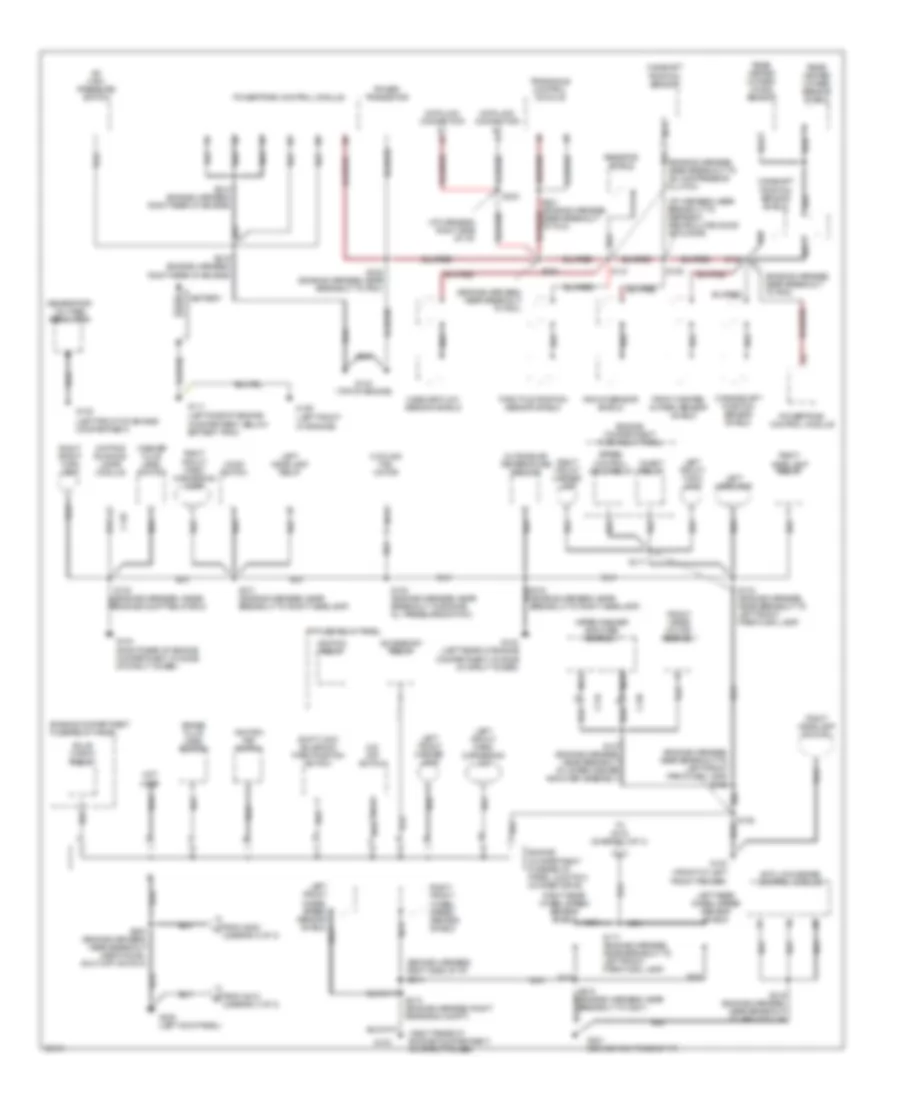
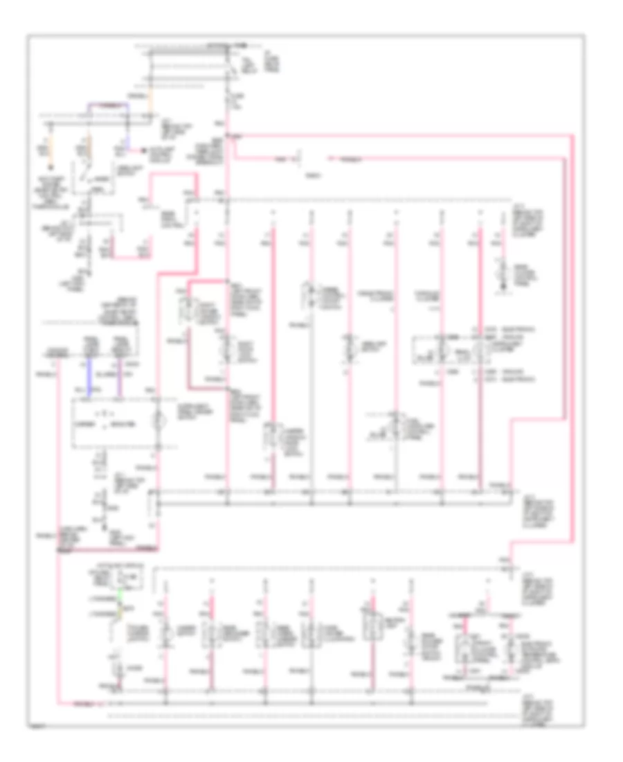
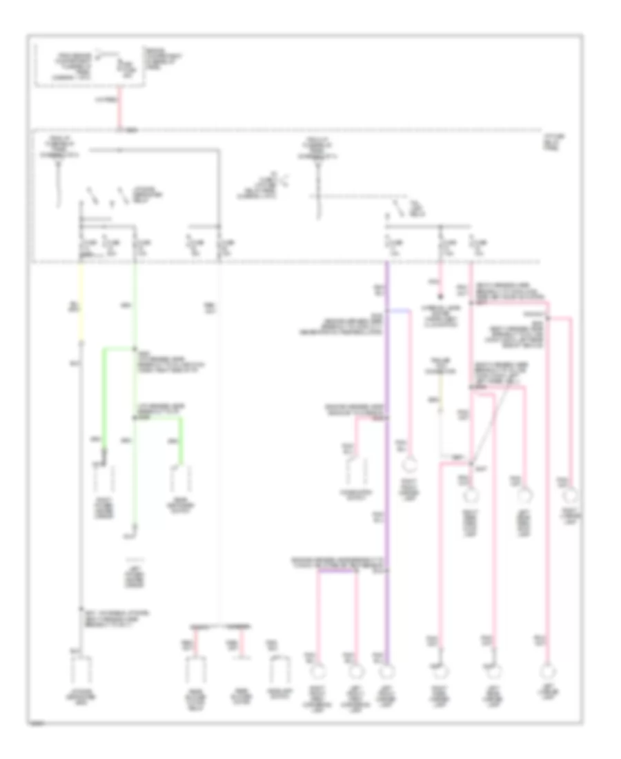
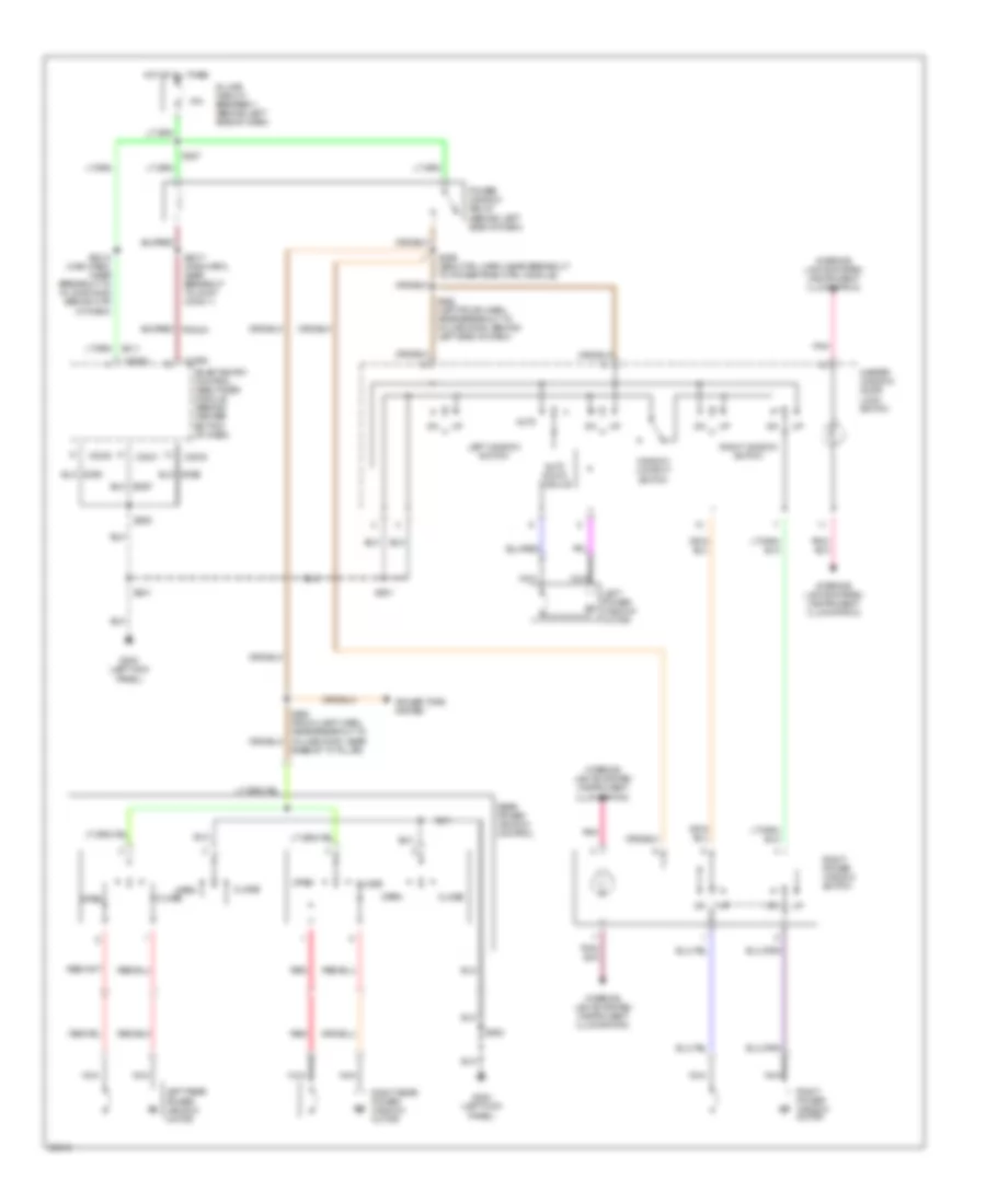
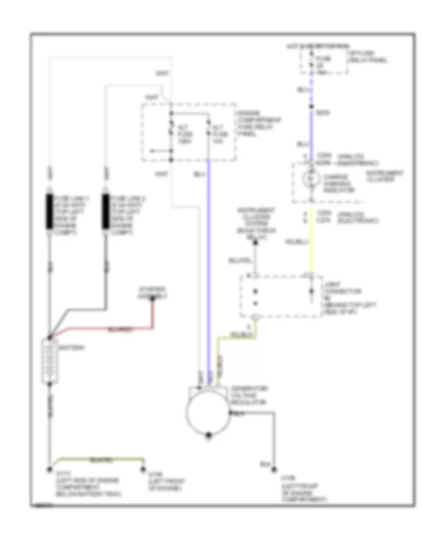
AIR CONDITIONING
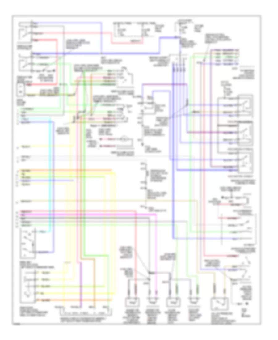
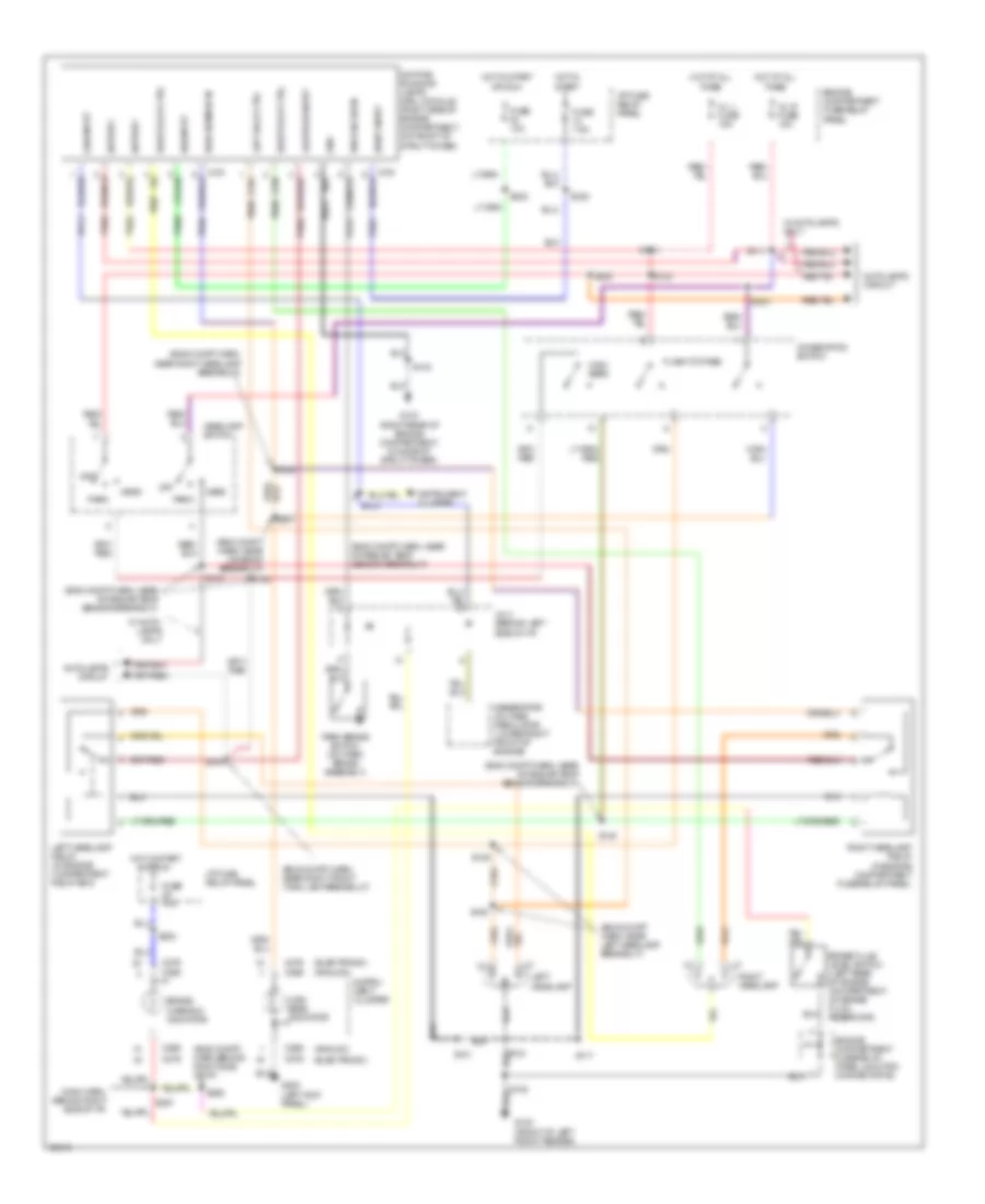
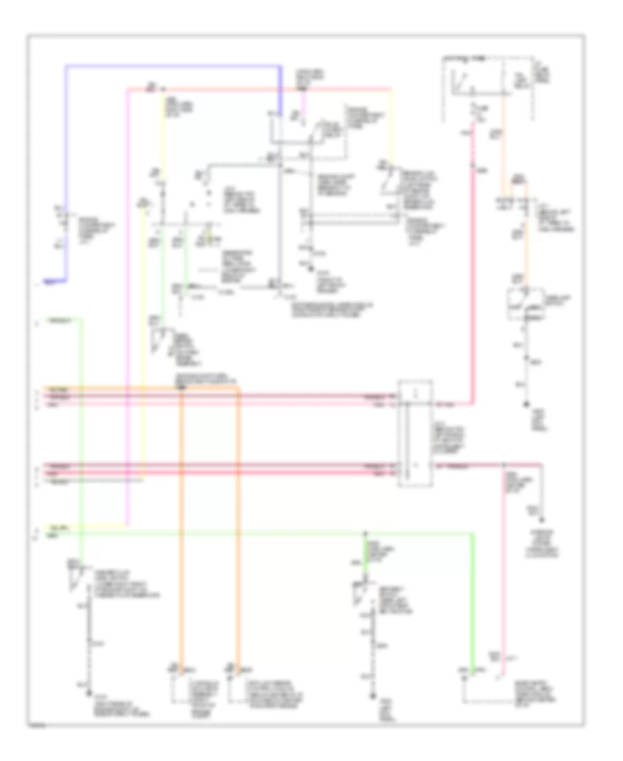
A/C Wiring Diagram, Auto A/C (1 of 2) for Mercury Villager LS 1997
 https://portal-diagnostov.com/license.html
Automotive Electricians Portal FZCO
Automotive Electricians Portal FZCO
https://portal-diagnostov.com/license.html
https://portal-diagnostov.com/license.html
Automotive Electricians Portal FZCO
Automotive Electricians Portal FZCO
List of elements for A/C Wiring Diagram, Auto A/C (1 of 2) for Mercury Villager LS 1997:
- (center of i/p)
- (main harn, behind right side of i/p)
- (right side of i/p)
- Acc
- All times
- Autolamp module
- Blower motor
- Blw fuse 65a
- C2027
- C2028
- C2029
- C212
- E/m switch
- Eatc module
- Electronic automatic temperature control module (center of i/p)
- Engine compart- ment fuse/ relay panel
- F/r door
- F/r door actuator
- Floor/panel
- Fresh/recirculation door actuator (behind right side of i/p, on plenum)
- Front blend door actuator (behind right side of i/p, on plenum)
- Front blower motor relay
- Front blower motor/ speed controller
- Frt blend door
- Frt blend door (cool)
- Frt blend door (warm)
- Frt blo motor relay
- Fuse 10a
- Fuse 20a
- Fuse 7.5a
- G201
- G202 (left side of i/p)
- Ground
- Ha01
- Ha02
- Ha04
- Ha06
- Ha09
- Ha11
- Ha12
- Ha13
- Ha14
- Ha15
- Ha16
- Ha17
- Ha18
- Ha20
- Ha21
- Ha22
- Ha23
- Ha24
- Ha28
- Hae2
- Hc02
- Hc03
- Hc04
- Hc05
- Hc06
- Hc08
- Hc09
- Hc10
- Hc11
- Hc12
- Hc13
- Hc14
- Hc15
- Hc16
- Hc17
- Hc18
- Hc19
- Hc20
- Hc21
- Hce2
- Hce5
- Hce7
- Hj02
- Hj03
- Hj05
- Hj06
- Hj07
- Hj10
- Hj12
- Hot at
- Hot at all times
- Hot in run
- I/p fuse/ relay panel
- I/p fuse/relay panel
- Ignition
- Ignition switch
- Ih01
- Ih02
- Ih91
- Illumination
- In car temp sensor
- Instrument cluster
- Interior lights system
- J/c 1 (left i/p)
- Lo pressure
- Lock
- Mode actuator
- Mode actuator (behind center of i/p)
- Nca
- Off
- Pnk
- Position switches
- Power
- Rea water vlv sol
- Rear blend dr act
- Rear climate control panel
- Rear vent door act
- Rr blend door
- Rr blower motor
- Rr blower motor relay
- Rr blw motor sw
- Rr cc panel
- Rr cc power
- Rr cc switch (frt)
- Rr climate ctrl panel
- Run
- S203 (main harn, behind right side of i/p)
- S209
- S231 (main harn, behind right side of i/p)
- S236 (main harn, near front blower motor breakout)
- S249 (main harn, behind right side of i/p)
- S315
- S316
- Sensor input
- Sensor power
- Side of i/p)
- Start
- Sunload sensor
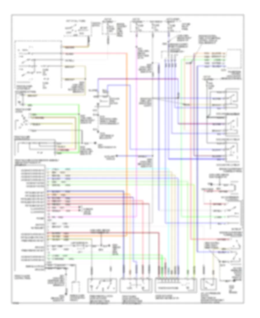
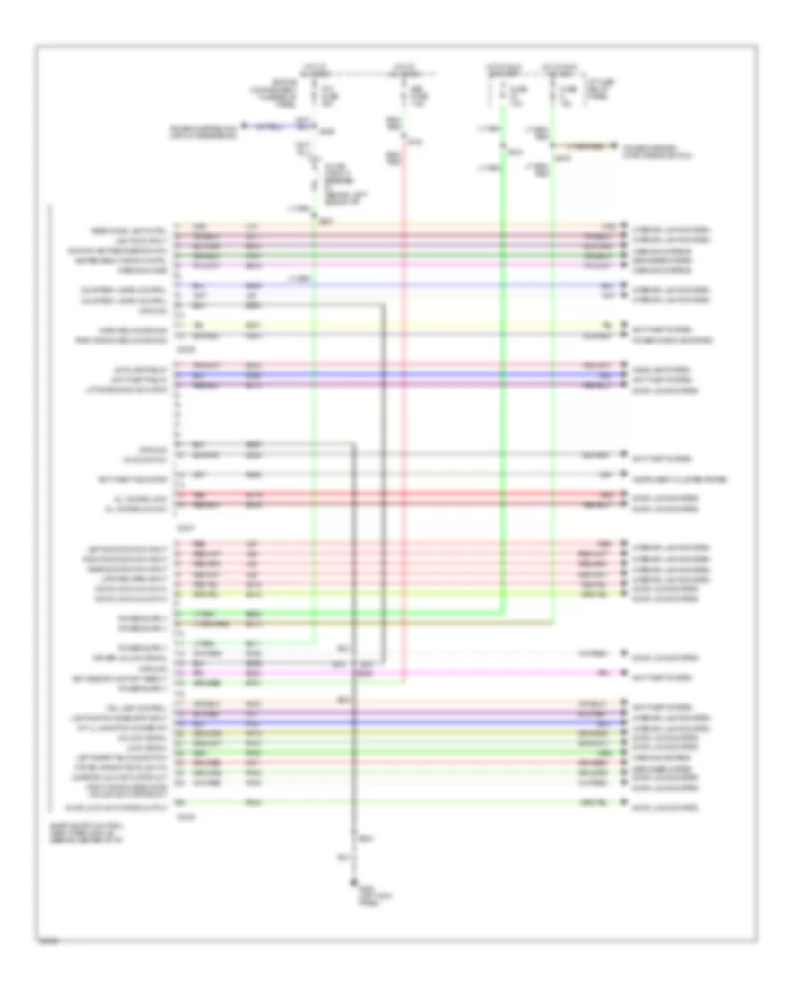
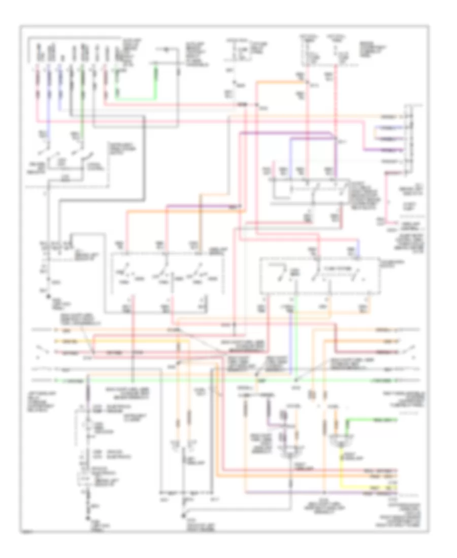
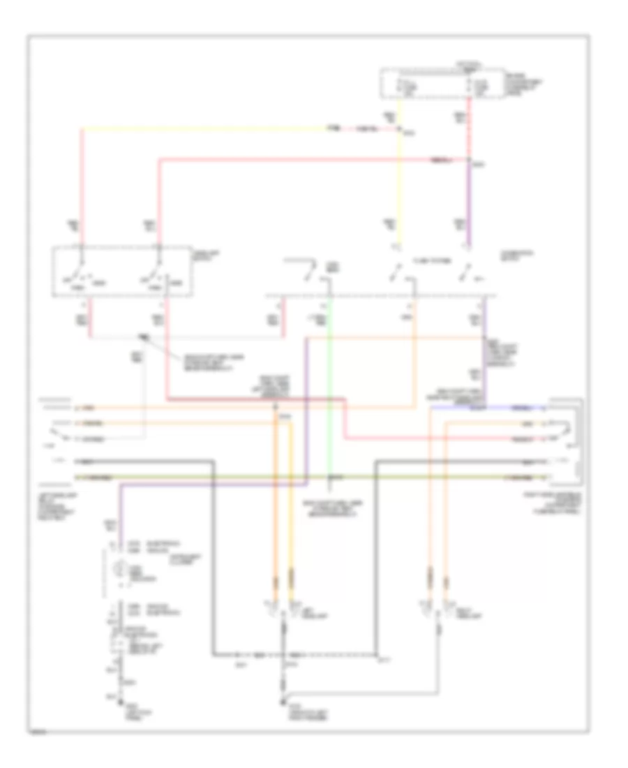
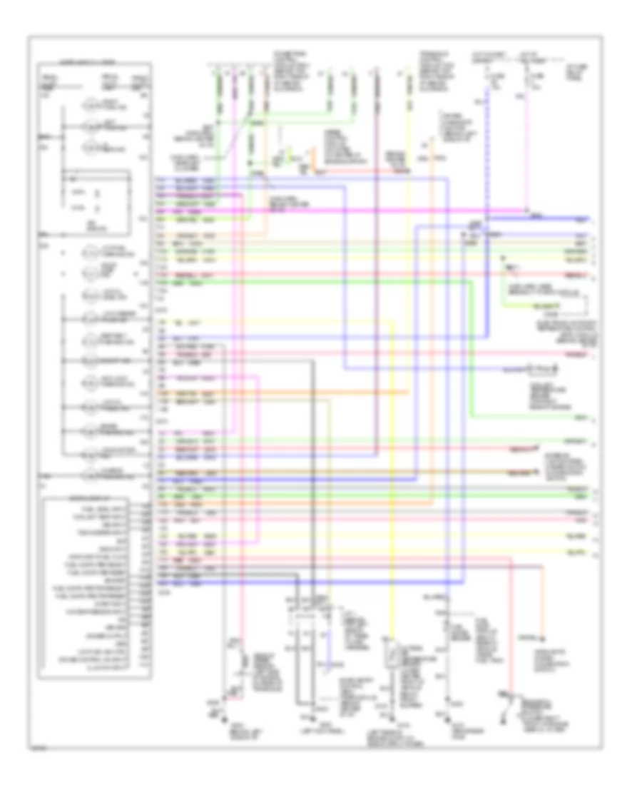
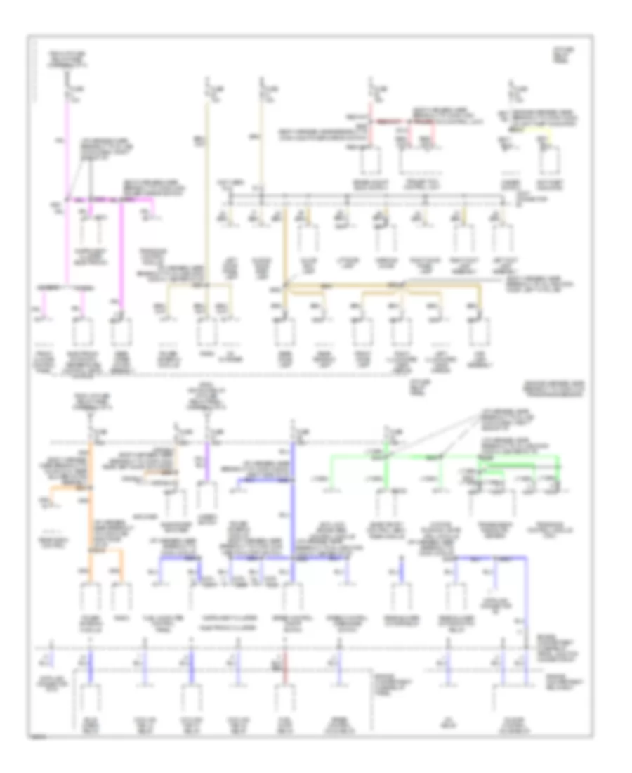
A/C Wiring Diagram, Auto A/C (2 of 2) for Mercury Villager LS 1997
List of elements for A/C Wiring Diagram, Auto A/C (2 of 2) for Mercury Villager LS 1997:
- (center rear of engine)
- (eng control harn, right rear of eng)
- (eng room harn, left side of eng compt)
- (engine control harn, in powertrain control module (pcm) breakout)
- (front center
- (main harn, behind center of i/p)
- (main harn, behind left side of i/p)
- (main harn, behind right side of i/p)
- (main harn, near elect auto temp module breakout)
- (main harn, near left cowl panel)
- (main harn, near rear blower motor resistor assembly breakout)
- (main harn, near rear blower motor switch relay breakout)
- (right side
- (sub harn (eatc), behind center of i/p)
- A/c compressor clutch coil
- A/c high pressure switch (right front of engine)
- A/c low pressure switch (right side of engine compartment, on accumulator)
- A/c relay
- Ambient air temperature sensor 1
- Ambient air temperature sensor 2
- C275
- Compartment)
- Cooling fan hi1 relay
- Cooling fan hi2 relay
- Cooling fan lo relay
- Cooling fan motor
- Engine compart- ment fuse/relay junction connector 1
- Engine compartment fuse/relay panel
- Fa06
- Fa12
- Fuse 10a
- Fuse 15a
- G104 (left rear of eng compt)
- G134 (top of engine)
- G201
- G202 (left side of i/p)
- G202 (left side of i/p)
- G407 (center rear of vehicle)
- Ha41
- Ha45
- Hot at all times
- Hot in start or run
- Hx01
- I/p fuse/ relay panel
- In-car
- Interior lights system
- Nca
- Of engine
- Of i/p)
- Off
- Pnk
- Powertrain control module (pcm) (behind glove box)
- Rad fuse 65a
- Rear
- Rear blend door actuator (left side of passenger area, on rear plenum)
- Rear blower motor
- Rear blower motor relay
- Rear blower motor resistor assembly (left side of rear passenger area)
- Rear blower motor switch (front)
- Rear blower motor switch (rear)
- Rear blower motor switch relay
- Rear engine coolant valve solenoid (center rear of engine)
- Rear vent door actuator (left side of passenger area)
- Red
- S102 (eng room harn, near oil press switch breakout)
- S135
- S158
- S159
- S2015
- S210 (eng cntrl harn, right front of engine)
- S212
- S219
- S224 (main harn, behind right side of i/p)
- S237 (main harn, behind right side of i/p)
- S251
- S253 (main harn, near elect auto temp cntrl breakout)
- S288
- S289
- S290
- S304
- S311
- S313
- S314
- S318
- Sensor (behind ashtray, in i/p)
- Sunload sensor (right side of cargo area)
- Temperature
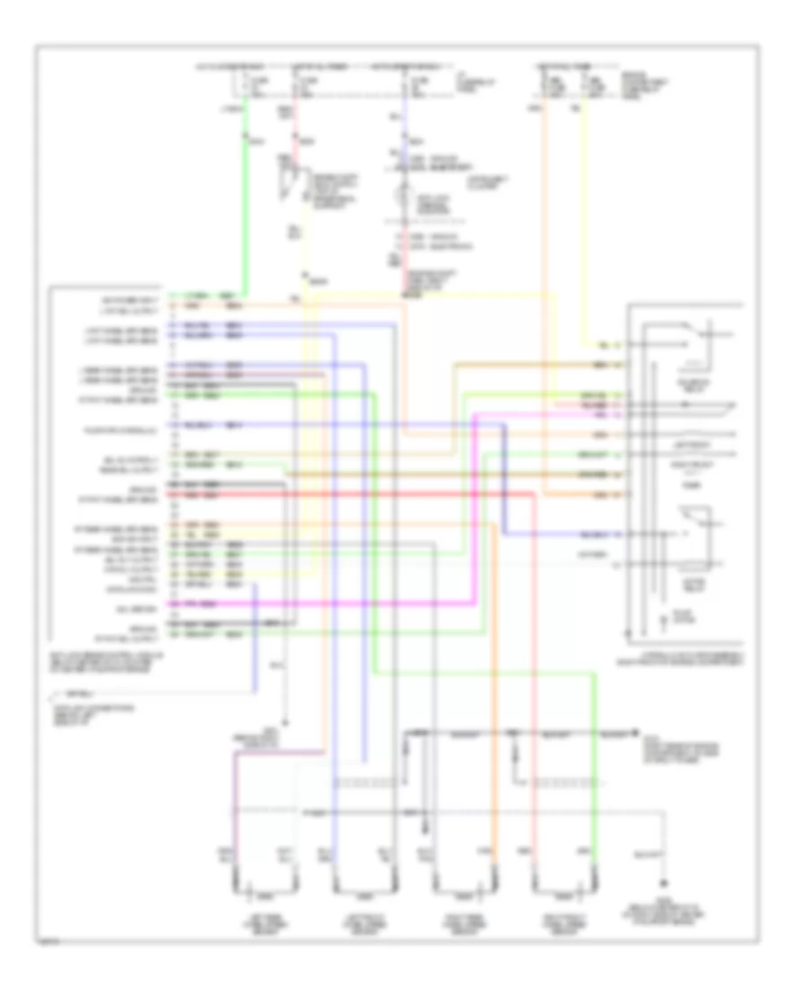
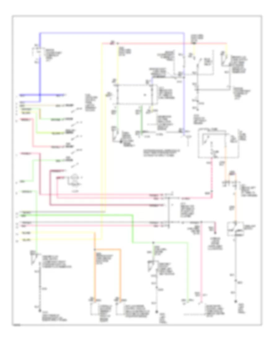
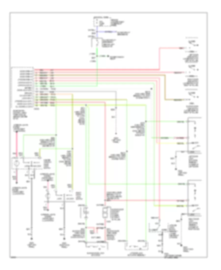
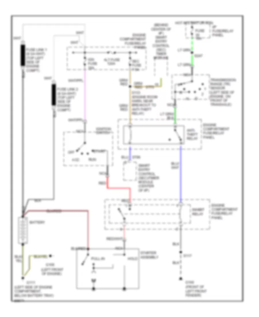
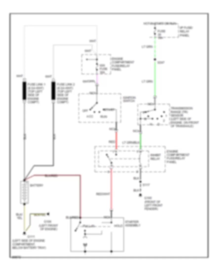
A/C Wiring Diagram, Manual A/C for Mercury Villager LS 1997
List of elements for A/C Wiring Diagram, Manual A/C for Mercury Villager LS 1997:
- (eng control harn, right rear of eng)
- (eng room harn, left side of eng compt)
- (engine control harn, in powertrain control module (pcm) breakout)
- (left rear of eng compt)
- (left side of i/p)
- (main harn, behind right side of i/p)
- (right side of i/p)
- A/c compressor clutch coil
- A/c high pressure switch (right front of engine)
- A/c low pressure switch (right side of engine compartment, on accumulator)
- A/c relay
- A/c request
- Acc
- All times
- Autolamp module
- Blw fuse 65a
- C201
- C203
- C275
- Cooling fan hi1 relay
- Cooling fan hi2 relay
- Cooling fan lo relay
- Cooling fan motor
- Engine compart- ment fuse/ relay panel
- Engine compart- ment fuse/relay junction connector 1
- Engine compartment fuse/relay panel
- Fa06
- Fa12
- Fresh/recirc dr act
- Fresh/recirculation door actuator (behind right side of i/p, on plenum)
- Front blend door actuator (behind right side of i/p, on plenum)
- Front blower motor
- Front blower motor relay
- Front blower motor resistor assembly (behind right side of i/p, in plenum)
- Front blower motor switch
- Front climate control panel
- Frt blend dr act
- Frt blend dr mtr act
- Frt blower mtr ctrl
- Fuse 10a
- Fuse 20a
- Fuse 7.5a
- G104
- G134 (top of engine)
- G201
- G201 (right side of i/p)
- G202 (behind left side of i/p)
- Ground
- Ha01
- Ha02
- Ha04
- Ha05
- Ha06
- Ha09
- Ha11
- Ha12
- Ha13
- Ha14
- Ha15
- Ha16
- Ha17
- Ha18
- Ha20
- Ha21
- Ha22
- Ha23
- Ha24
- Ha28
- Ha41
- Ha45
- Hae4
- Hb21
- He01
- Hot at
- Hot at all times
- Hot in run
- Hot in start or run
- Hx01
- I/p fuse/ relay panel
- I/p fuse/relay panel
- Ignition
- Ignition switch
- Ih01
- Ih91
- Illumination
- Interior lights system
- J/c 1
- Lock
- Mode act motor
- Mode actuator (behind center of i/p)
- Mode actuator sw in
- Nca
- Off
- Pnk
- Position switches
- Power
- Powertrain control module (pcm) (behind glove box)
- Rad fuse 65a
- Rear blower motor switch (front)
- Rear blw mtr sw
- Run
- S102 (eng room harn, near oil press switch breakout)
- S135
- S158
- S159
- S203
- S219
- S231 (main harn, behind right side of i/p)
- S236 (main harn, near front blower motor breakout)
- S248 (main harn, behind left side of i/p)
- S249 (main harn, behind right side of i/p)
- S251
- S287 (main harn, behind right side of i/p)
- S301 (main harn, near rear vent door actuator breakout)
- Start
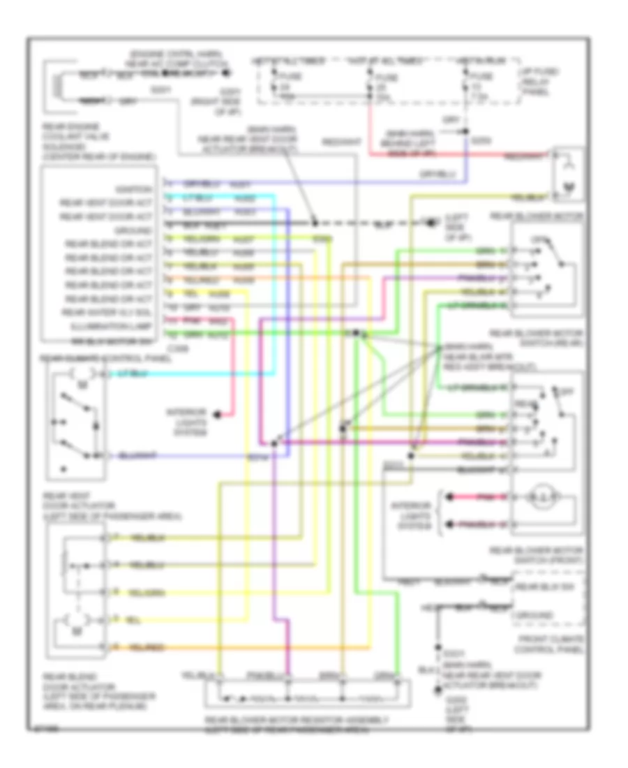
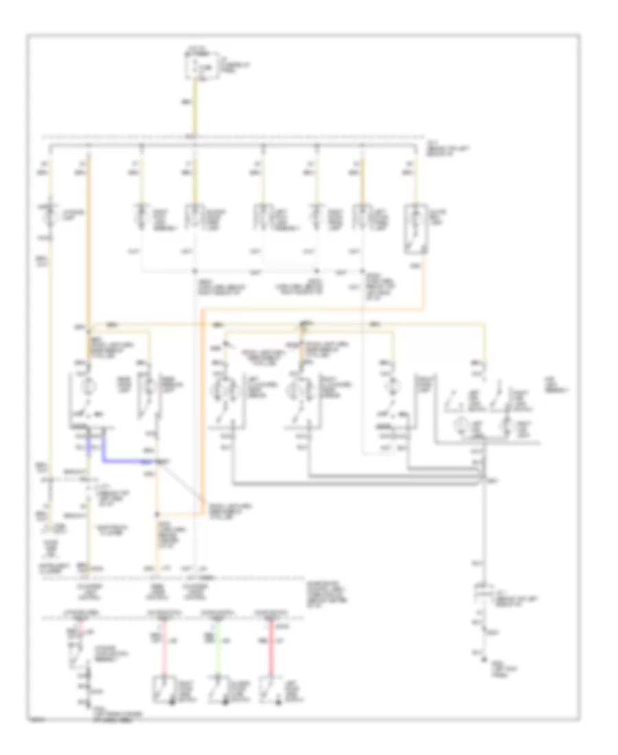
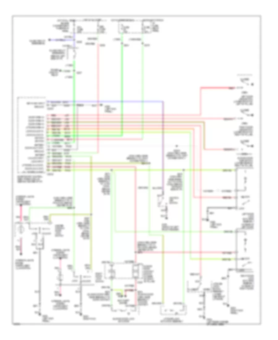
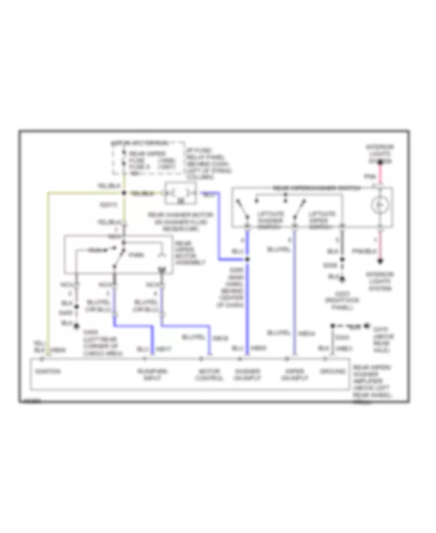
Rear A/C Wiring Diagram, Manual A/C for Mercury Villager LS 1997
List of elements for Rear A/C Wiring Diagram, Manual A/C for Mercury Villager LS 1997:
- (engine cntrl harn, near a/c comp clutch coil breakout)
- (left side of i/p)
- (main harn, behind left side of i/p)
- (main harn, near blwr mtr res ass'y breakout)
- (main harn, near rear vent door actuator breakout)
- C308
- Front climate control panel
- Fuse 15a
- Fuse 7.5a
- G201 (right side of i/p)
- G202
- G202 (left side of i/p)
- Ground
- Hb21
- He01
- Hj01
- Hj02
- Hj03
- Hj05
- Hj06
- Hj07
- Hj08
- Hj09
- Hj10
- Hj12
- Hje1
- Hot at all times
- Hot in run
- I/p fuse/ relay panel
- Ignition
- Ih02
- Illumination lamp
- Interior lights system
- Nca
- Nca ground
- Nca rear blw sw
- Off
- Pnk
- Rear
- Rear blend door actuator (left side of passenger area, on rear plenum)
- Rear blend dr act
- Rear blower motor
- Rear blower motor resistor assembly (left side of rear passenger area)
- Rear blower motor switch (front)
- Rear blower motor switch (rear)
- Rear climate control panel
- Rear engine coolant valve solenoid (center rear of engine)
- Rear vent door act
- Rear vent door actuator (left side of passenger area)
- Rear water vlv sol
- Rr blw motor sw
- S201
- S250
- S301
- S311
- S313
- S314
- S318
- S3o1
ANTI-LOCK BRAKES
Anti-lock Brake Wiring Diagrams for Mercury Villager LS 1997
List of elements for Anti-lock Brake Wiring Diagrams for Mercury Villager LS 1997:
- (analog)
- (electronic)
- (engine compt harn, right side of i/p) s286
- Abs fuse 20a
- Abs fuse 30a
- Anti-lock brake control module (below center of i/p, mounted on center i/p support brace)
- Anti-lock warning indicator
- Boo sw input
- Brake on/off (boo) switch (top of brake pedal support)
- Bs01
- Bs02
- Bs04
- Bs05
- Bs08
- Bs09
- Bs14
- Bs17
- Bs18
- Bs21
- Bs23
- Bs24
- Bs25
- Bs26
- Bs27
- Bs28
- Bs29
- Bs30
- Bs32
- Bs35
- C268
- C276
- Data link conn
- Data link connector #2 (behind left side of i/p)
- Eb10
- Eb20
- Eb34
- Engine compartment fuse/relay panel
- Fuse 10a
- Fuse 15a
- G103 (right rear of engine compartment, on side of strut tower)
- G201 (behind right side of i/p)
- G206 (below center of i/p, on right side of center i/p support brace)
- Ground
- Hot at all times
- Hot in start or run
- Hydraulic actuator assembly (right front of engine compartment)
- I/p fuse/relay panel
- Ign power input
- Ind ctrl
- Instrument cluster
- L fnt sol output
- L fnt wheel spd sens
- L rear wheel spd sens
- Left front
- Left front wheel speed sensor
- Left rear wheel speed sensor
- Motor relay
- Mtr rly output
- Nca
- Pump motor
- Pump mtr (hydraulic)
- Rear
- Rear sol output
- Red
- Right front
- Right front wheel speed sensor
- Right rear wheel speed sensor
- Rt fnt sol output
- Rt fnt wheel spd sens
- Rt rear wheel spd sens
- S2006
- S213
- S214
- S215
- S216
- S224
- S239
- S244
- Sol return
- Sol rly output
- Sol rly/mtr rly
- Solenoid relay
ANTI-THEFT
Anti-theft Wiring Diagram for Mercury Villager LS 1997
List of elements for Anti-theft Wiring Diagram for Mercury Villager LS 1997:
- (in front of sliding door)
- (in rear of * right "b" pillar)
- (main harn, left rear side of vehicle)
- (slding door harn, near breakout to slding door contact sw)
- (slding door harn, near breakout to slding door contact sw) s335
- Anti- theft indicator
- Anti- theft relay
- Anti-theft cntrl
- Battery
- C2030
- C2031
- C2032
- C311
- C329
- Door lk input
- Door locks system (door lock switches)
- Dr unlk input
- Engine compartment fuse/relay panel
- Engine compartment relay box
- Er05
- Exterior lights system
- Fuse 10a
- G103 (right rear of engine compt, on strut tower)
- G200 (left kick panel)
- G203 (right kick panel)
- G404 (left rear corner of cargo area)
- G404 (left rear of carg0 area)
- Ground
- Headlamp cntrl
- Headlights system (autolamps)
- Hood sw input
- Hood switch
- Horn control
- Horns system (horn relay)
- Hot at all times
- Hot in acc or run
- Hot in start or run
- I/p fuse/ relay panel
- Ignition
- Inline circuit breaker #1 (behind left side of i/p)
- Interior lights system (door jamb switches)
- Keyless entry system
- Lefgate dr act
- Left door key lock switch
- Left dr open in
- Li87
- Li89
- Li90
- Li94
- Liftgate key lock switch
- Liftgate latch switch assembly (lower center of liftgate)
- Liftgate lock actuator assembly (lower right center of liftgate)
- Liftgate open in
- Lock
- Lock input
- Nca
- Ph10
- Ph19
- Ps95
- Red
- Right door key lock switch
- Right dr open in
- S101
- S133
- S205
- S206
- S227
- S240
- S244
- S279
- S329
- S330
- S331
- S332
- S333
- S334
- S403
- S405
- S500
- S600
- Sc06
- Sc09
- Sc11
- Sc13
- Sc14
- Sc19
- Sc21
- Sc22
- Sc23
- Sc24
- Sce1
- Sce2
- Sce7
- Sec fuse 7.5a
- Sldng dr open in
- Sldng dr sw
- Sliding door contact switch
- Sliding door control unit (in sliding door)
- Sliding door key lock switch
- Sliding door lock actuator (rear of sliding door)
- Smart entry control (sec)/ timer module (behind center of i/p)
- Solid state
- St70
- St96
- Starting system (inhibit relay)
- Tail lamp cntrl
- Transmission range (tr) sensor (left side of engine, front of transaxle)
- Unlock
- Unlock input
- W/ fixed glass
- W/ movable glass
BODY COMPUTER
Body Computer Wiring Diagrams for Mercury Villager LS 1997
List of elements for Body Computer Wiring Diagrams for Mercury Villager LS 1997:
- All doors lock
- All doors unlock
- Anti-theft indicator
- Anti-theft relay
- Anti-theft system
- Autolamp relay
- Bdy side dr contact assmly
- C2030
- C2031
- C2032
- Courtesy lamps control
- Defogger system
- Door lock actuators output
- Door lock/unlock in
- Door locks system
- Driver unlock signal
- Engine compartment fuse/relay panel
- Er05
- Er10
- Er19
- Fuse 10a
- G200 (left kick panel)
- Ground
- Headlamp system
- Heated back window cntrl
- Hf01
- Hf07
- Hood switch
- Horn relay ground
- Hot at all times
- Hot in run or acc
- Hot in run or start
- Htd bk window sw & lght in
- I/p fuse/ relay panel
- Ignition key reminder switch
- Inline circuit breaker #1 (behind left side of i/p)
- Instrument cluster system
- Int illumination dimmer sw
- Interior lights system
- Ip01
- Ip02
- Jc11
- Left door switch input
- Left safety buckle switch
- Lgate dr unlk actuator out
- Li70
- Li87
- Li89
- Li90
- Li91
- Li94
- Liftgate door actuator
- Liftgate open input
- Light switch rheostat input
- Lights on input
- Lock signal
- P/w fuse 30a
- Pd04
- Ph10
- Ph19
- Ph32
- Ph35
- Ph38
- Ph43
- Power distribution (circuit breaker #2)
- Power mirrors (pwr mirror switch)
- Power windows system
- Pp42
- Ps95
- Pwr window relay ground
- Rear dome lamp cntrl
- Red
- Right door & side door unlock actuators out
- Right door switch input
- S133
- S206
- S226
- S227
- S243
- S244
- S279
- Sc06
- Sc09
- Sc11
- Sc13
- Sc14
- Sc15
- Sc16
- Sc19
- Sc21
- Sc22
- Sc23
- Sc24
- Sc25
- Sce1
- Sce2
- Sce7
- Sec fuse 7.5a
- Side door switch input
- Smart entry control (sec)/timer module (behind center of i/p)
- St70
- St96
- Tail lamp control
- Unlock signal
- Warning chime
- Warning systems
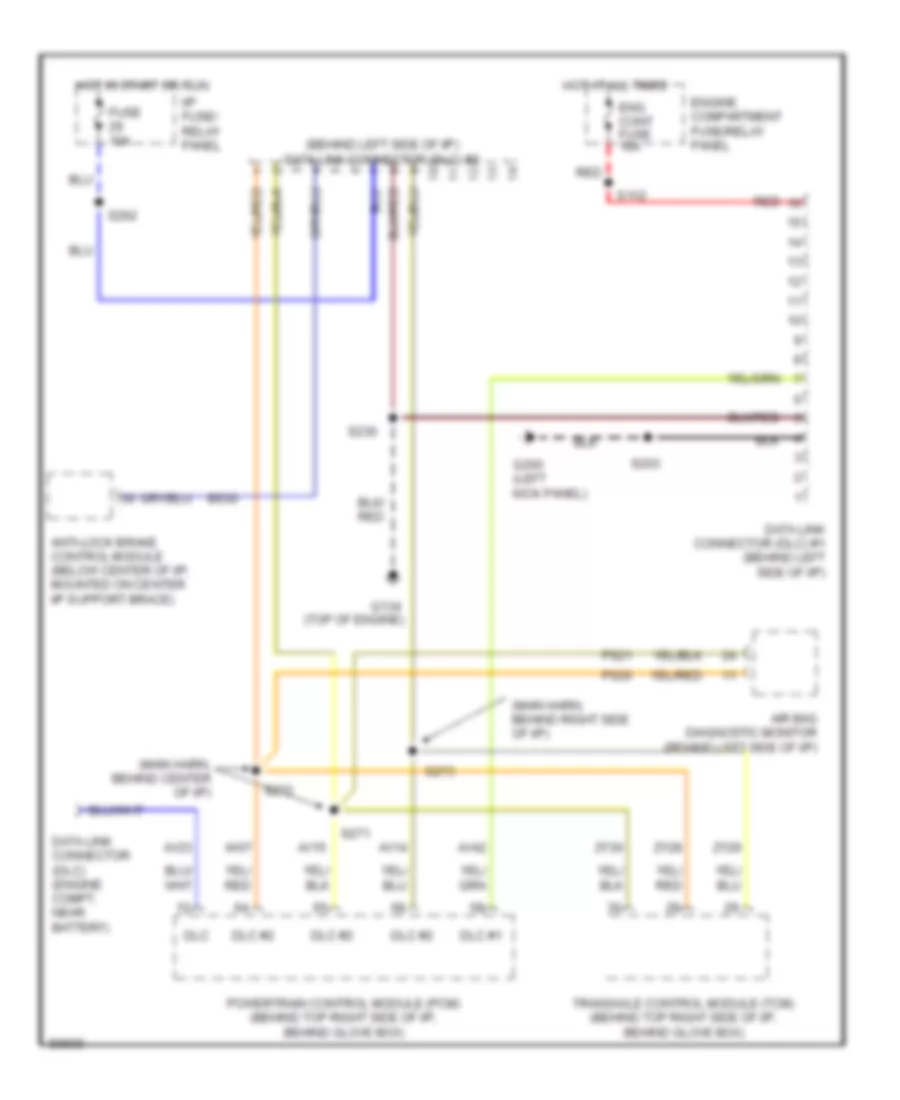
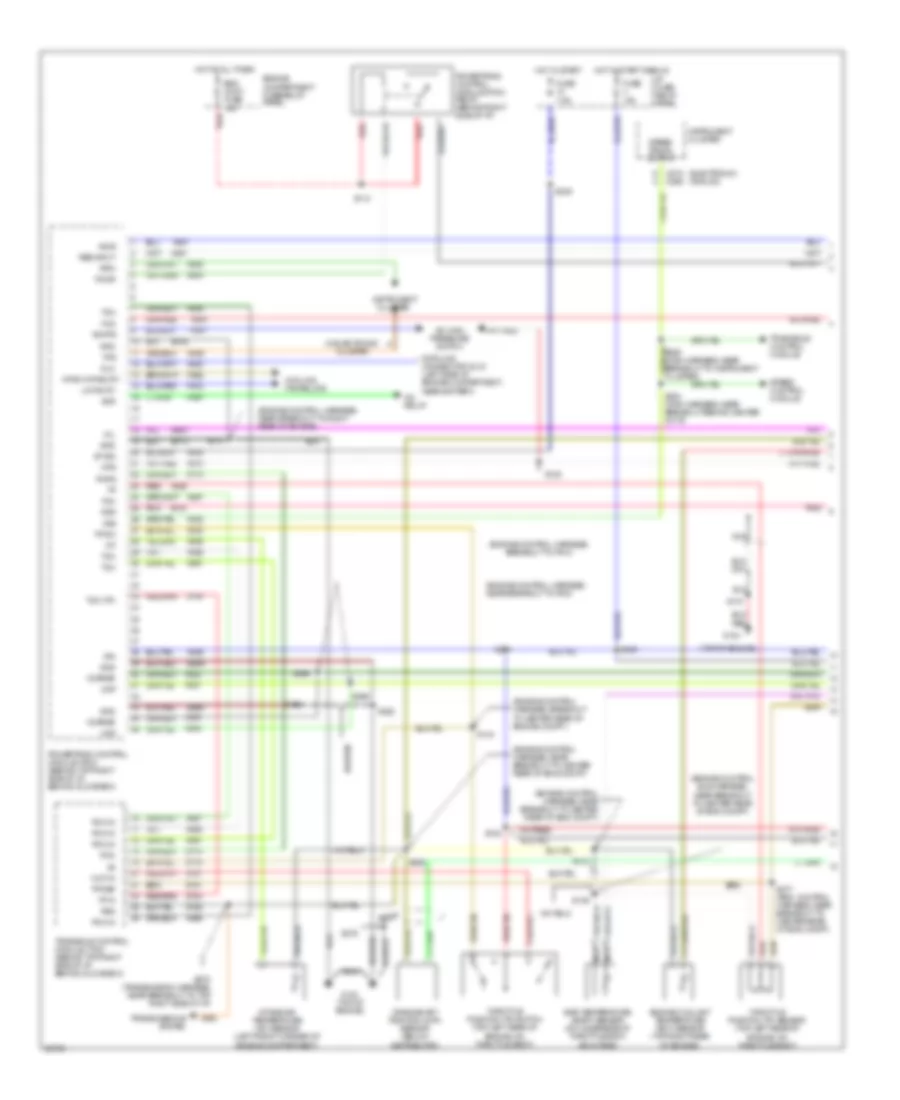
COMPUTER DATA LINES
Computer Data Lines for Mercury Villager LS 1997
List of elements for Computer Data Lines for Mercury Villager LS 1997:
- (behind left side of i/p) data link connector (dlc) #2
- (main harn, behind center of i/p)
- (main harn, behind right side of i/p)
- Air bag diagnostic monitor (behind left side of i/p)
- Anti-lock brake control module (below center of i/p, mounted on center i/p support brace)
- Av07
- Av14
- Av15
- Av23
- Av42
- Bs30
- Data link connector (dlc) #1 (behind left side of i/p)
- Data link connector (dlc) (engine compt, near battery)
- Dlc
- Dlc #1
- Dlc #2
- Eng cont fuse 10a
- Engine compartment fuse/relay panel
- Fuse 10a
- G134 (top of engine)
- G200 (left kick panel)
- Hot at all times
- Hot in start or run
- I/p fuse/ relay panel
- Powertrain control module (pcm) (behind top right side of i/p, behind glove box)
- Ps20
- Ps21
- Red
- S112
- S203
- S230
- S262
- S271
- S272
- S273
- Transaxle control module (tcm) (behind top right side of i/p, behind glove box)
- Zy28
- Zy29
- Zy30
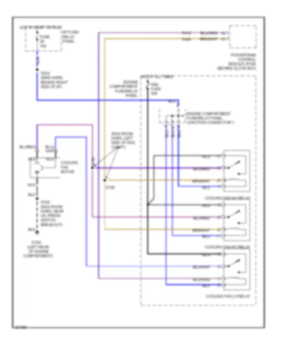
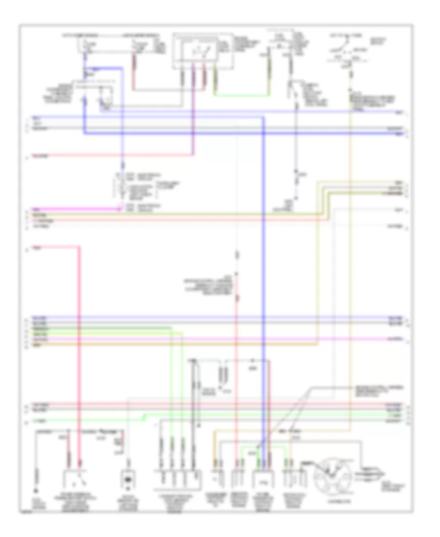
COOLING FAN
Cooling Fan Wiring Diagram for Mercury Villager LS 1997
List of elements for Cooling Fan Wiring Diagram for Mercury Villager LS 1997:
- (eng room harn, left side of eng compt)
- (left rear of engine
- Compartment)
- Cooling fan hi1 relay
- Cooling fan hi2 relay
- Cooling fan lo relay
- Cooling fan motor
- Engine compartment fuse/relay panel
- Engine compartment fuse/relay panel junction connector 1
- Fa06
- Fa12
- Fuse 10a
- G104
- Hot at all times
- Hot in start or run
- I/p fuse/ relay panel
- Nca
- Powertrain control module (pcm) (behind glove box)
- Rad fuse 65a
- S102 (eng room harn, near oil press switch breakout)
- S158
- S159
- S224 (main harn, behind right side of i/p)
CRUISE CONTROL
Cruise Control Wiring Diagram for Mercury Villager LS 1997
List of elements for Cruise Control Wiring Diagram for Mercury Villager LS 1997:
- "cruise" indicator
- "on"
- "on" input
- (analog) (electronic)
- (behind center of i/p) smart entry control (sec) timer module
- (behind left side of i/p, taped to main harness)
- (engine harn, near breakout to intake air temp- erature sensor)
- (left kick panel)
- (main harn, behind center of i/p) s282
- (main harness, behind center of i/p) s254
- (right side of engine, compartment on front of strut tower)
- Analog cluster
- Anti- theft relay
- Brake on/off (boo) switch (on brake pedal suport)
- Brake pedal input
- C266
- C268
- C268 c272
- C272
- C274
- Cancel
- Clock- spring assembly
- Cluster
- Control en/dis sw
- Control switch input
- Cruise ind ctrl
- Data line
- Ej04
- Ej06
- Ej07
- Ej08
- Ej09a
- Ej10
- Ej14
- Ej15
- Ej16
- Ej17
- Ej40
- Eje1
- Ejo1
- Ejo2
- Electronic cluster
- Engine compart- ment fuse/ relay panel
- Engine compart- ment fuse/ relay panel junction conn- ector #1
- Engine compartment fuse/relay panel
- Fuse 10a
- Fuse 15a
- G100 (front of left front fender)
- G200
- G200 (left kick panel)
- G202 (behind left side of i/p)
- G203 (right kick panel)
- Ground
- Horn fuse 15a
- Horn relay (in engine compt fuse/ relay
- Horn switch
- Hot at all times
- Hot in start or run
- I/p fuse/ relay panel
- Indicator
- Inhibit relay
- Input
- Instrument
- Instrument cluster
- Interior lights system
- Joint connector #1
- Joint connector #1 (behind left side of i/p, taped to main harness)
- Motor ctrl
- Mtr/sol pwr
- Nca
- Off
- Ohms
- Output
- Panel)
- Pnk
- Red/
- Resume/ accel
- S115
- S117
- S140
- S2016 (main harness, near breakout to speed control module)
- S203
- S207
- S229
- S239
- S247
- S258
- S261
- S283 (main harness, behind center of i/p)
- S285 (engine harn, behind left side of i/p)
- Set/ coast
- Shift lock solenoid/ park position switch
- Speed control
- Speed control actuator
- Speed control disengage switch (on brake pedal support)
- Speed control hold relay
- Speed control module (below center of i/p)
- Speed control on/off switch
- Speed control switch assembly
- Speed signal
- Steering column ground
- Transaxle control module (tcm) (behind right side of i/p)
- Transaxle)
- Transmission range (tr) sensor (on front of transaxle)
- Vacuum on/off
- Vacuum output
- Vacuum pump motor
- Vacuum solenoid
- Vehicle speed input
- Vehicle speed sensor (vss) (on rear of
- Vent solenoid
- W/ anti-theft
- W/o anti-theft
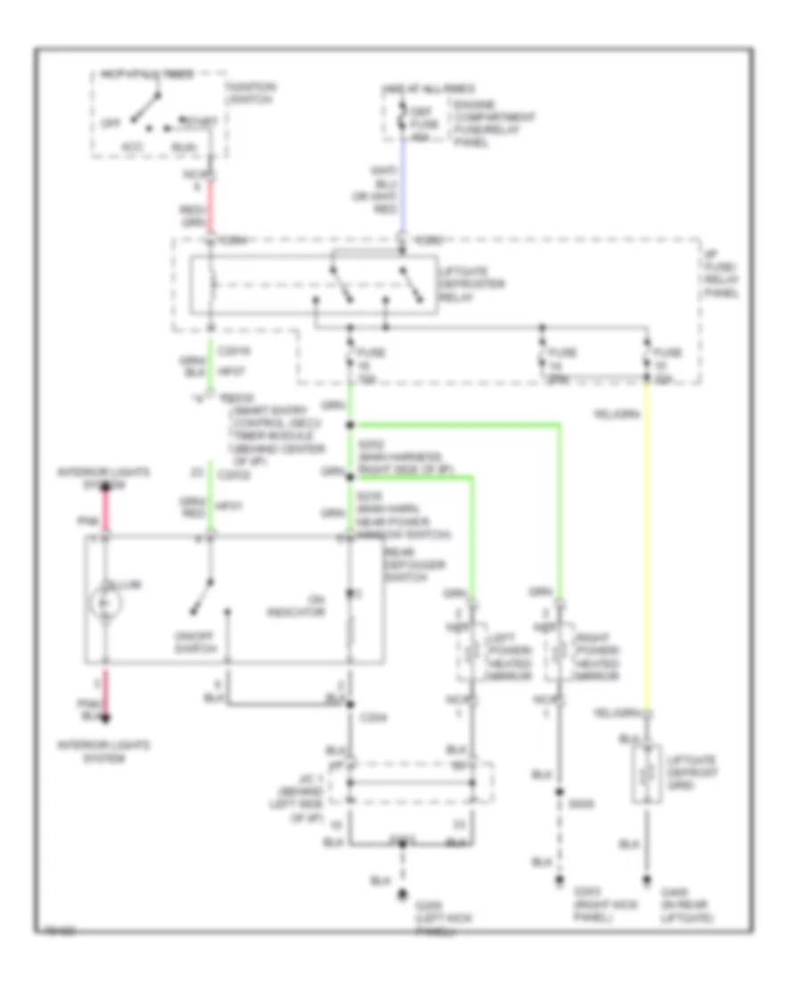
DEFOGGERS
Defogger Wiring Diagram for Mercury Villager LS 1997
List of elements for Defogger Wiring Diagram for Mercury Villager LS 1997:
- Acc
- C2016
- C202
- C2030
- C2032
- C204
- Def fuse 45a
- Engine compartment fuse/relay panel
- Fuse 10a
- Fuse 20a
- G200 (left kick panel)
- G203 (right kick panel)
- G406 (in rear liftgate)
- Hf07
- Hot at all times
- I/p fuse/ relay panel
- Ignition switch
- Illum
- Indicator
- Interior lights system
- J/c 1 (behind left side of i/p)
- Left power/ heated mirror
- Liftgate defrost grid
- Liftgate defroster relay
- Nca
- Near power window switch)
- Off
- On/off switch
- Pnk
- Rear defogger switch
- Right power/ heated mirror
- Run
- S203
- S600
- Smart entry control (sec)/ timer module (behind center of i/p)
- Start
ENGINE PERFORMANCE
3.0L
3.0L, Engine Performance Wiring Diagrams (1 of 3) for Mercury Villager LS 1997
List of elements for 3.0L, Engine Performance Wiring Diagrams (1 of 3) for Mercury Villager LS 1997:
- mil
- (electronic) (analog)
- (engine control harness, breakout to center rear of engine compt.)
- (engine control harness, breakout to pcm)
- (engine control harness, near breakout to center rear of eng compt)
- (engine control harness, near breakout to pcm)
- (engine control harness, near breakout to right rear of engine)
- (engine control sub harness, near breakout to center rear of eng compt)
- (top of engine)
- A/c high pressure switch
- A/c relay
- Achps
- Acr
- Av01
- Av02
- Av04
- Av12
- Av20
- Av22
- Av23
- Av28
- Av30
- Av31
- Av32
- Av33
- Av34
- Av36
- Av40
- Av53
- Av56
- Av57
- Av58
- Av61
- Av73
- Av91
- Avo5
- C272 c268
- Ckp
- Ckpref
- Cluster
- Cooling fan relays
- Crankshaft position (ckp) sensor (below
- Data link connector (dlc) (left side of engine compartment, near battery)
- Distributor)
- Dlc
- Egr temperature (egrt) sensor (on underside of throttle body, air intake)
- Eng cont fuse 10a
- Engine compartment fuse/relay panel
- Engine compartment)
- Engine coolant temperature (ect) sensor (top right rear
- Engine, on throttle body)
- Ep06
- Ep13
- Es39
- Es48
- Fa06
- Fa12
- Ffs
- Fuse 10a
- Fuse 7.5a
- G134
- G134 (top of engine)
- Gnd
- Ha41
- Hfan1/hfan2 ry
- Hot at all times
- Hot in start
- Hot in start or run
- Hps
- Hx01
- I/p fuse/ relay panel
- Iat
- Ign
- Ings
- Inj3
- Instrument
- Instrument cluster
- Intake air temperature (iat) sensor (left front corner of
- Isi
- Lo fan ry
- Nca
- Nr01
- Of engine)
- Pcm
- Pcm in
- Pcmr
- Pnk
- Pnps
- Powertrain control module (pcm) (behind top right side of i/p, behind glove box)
- Powertrain control module (pcm) relay (behind right side of i/p)
- Psg
- Psp
- Red
- Res input
- Rpm
- S108
- S110
- S112
- S131
- S134
- S135
- S136
- S154
- S218
- S222
- S238
- S241
- S242
- S254 (main harness, near breakout behind center of i/p)
- S265
- S266
- S269
- S277 (eng. control harness, near breakout to center rear of eng compt)
- S278
- S278 (transmission harness, near breakout to top right side of i/p)
- Speed control module
- Speed signal output
- St sig
- Tcm
- Tcm (tp)
- Throttle position (tp) sensor (top left rear of
- Throttle position (tp) switch (top left rear of
- Tp in
- Tp ref
- Tp sw
- Transaxle control module
- Transaxle control module (tcm) (behind top right side of i/p, behind glove box)
- Transmissions system
- Vss
- W/ electronic cluster
- Wot in
- Zy13
- Zy14
- Zy21
- Zy31
- Zy34
- Zy35
3.0L, Engine Performance Wiring Diagrams (2 of 3) for Mercury Villager LS 1997
List of elements for 3.0L, Engine Performance Wiring Diagrams (2 of 3) for Mercury Villager LS 1997:
- (analog)
- (electronic)
- (engine control harness, near breakout to ignition coil)
- (left kick panel)
- (top of engine)
- (top right front of engine)
- Acc
- C268
- C276
- Camshaft position (cmp) sensor
- Ckp out
- Ckp ref
- Condenser (top right front of i/p)
- Distributor
- Engine compartment fuse/relay panel
- Engine compartment fuse/relay panel junction connector #1
- F pump fuse 15a
- Fuel pump
- Fuel pump module (inside fuel tank)
- Fuel pump relay
- Fuse 10a
- G119 (right front of engine)
- G134
- G134 (top of engine)
- G200
- Gnd
- Hot at all times
- Hot in start or run
- I/p fuse/ relay panel
- Ignitiion switch
- Ignition coil (top right front of engine)
- Inertia fuel shut-off switch (behind left cowl panel)
- Instrument cluster
- Knock sensor (ks) (left side of engine)
- Lock
- Malfunction indicator lamp "check engine"
- Nca
- Pnk
- Power steering pressure (psp) switch (right rear side of engine compartment)
- Power transistor (top right front of engine)
- Pwr in
- Red
- Resistor (top right front of engine)
- Run
- S109
- S119 (engine room harness, near breakout to eng compt fuse/relay panel)
- S120
- S121 (engine control harness, breakout to engine compartment, near right side of battery)
- S128
- S222
- S299
- S300
- Start
3.0L, Engine Performance Wiring Diagrams (3 of 3) for Mercury Villager LS 1997
List of elements for 3.0L, Engine Performance Wiring Diagrams (3 of 3) for Mercury Villager LS 1997:
- (behind left side of i/p)
- (engine control harness, near breakout to pcm relay)
- (engine control harness, near breakout to pcm)
- (engine control sub harness, near breakout to injector 1)
- (front right side of engine compartment)
- (main harness, near breakout to center of i/p)
- (main harness, near breakout to top right side of i/p) s273
- (transaxle control harness, near breakout to right side of battery)
- (under center of vehicle)
- Av07
- Av08
- Av09
- Av14
- Av15
- Av16
- Av17
- Av18
- Av19
- Av21
- Av27
- Av37
- Av38
- Av42
- Av46
- Av47
- Av51
- Av52
- Av53
- Av55
- Av59
- Av60
- Av62
- Av63
- Av64
- Av66
- Av99
- Cmp
- Data link connector #1 (behind left side of i/p)
- Data link connector (dlc) #2
- Dlc
- Dlc #1
- Dlc #2
- Ect
- Egrt
- Egrv
- Engine compartment fuse/relay panel
- Engine compartment relay box
- Ep57
- Ep58
- Ep66
- Es90
- Exhaust gas recirculation (egr) valve (left rear of engine)
- Fho2s
- Front heated oxygen sensor (ho2s)
- Fuel injectors
- G134 (top of engine)
- G203 (right kick panel)
- Gnd
- Hot at all times
- Iacv2
- Idle air control (iac) valve #1 (top center of engine)
- Idle air control (iac) valve #2 (top center of engine)
- Idle air control valve relay
- Inj fuse 10a
- Inj1
- Inj2
- Inj3
- Inj4
- Inj5
- Inj6
- Maf+
- Maf-
- Mass air flow (maf) sensor (top left side of engine compartment)
- Nca
- Pcmr in
- Powertrain control module (pcm) (behind top right side of i/p, behind glove box)
- Pwr
- Rear heated oxygen sensor (ho2s)
- Rho2s
- S110
- S114
- S118
- S129
- S130
- S156
- S210
- S218
- S219
- S263
- S264
- S270
- S271 (main harness, near breakout to center of i/p)
- S272
- S308
- Sig rtn
- Transaxle control module (tcm) (behind top right side of i/p, behind glove box)
- Zy28
- Zy29
- Zy30
EXTERIOR LIGHTS
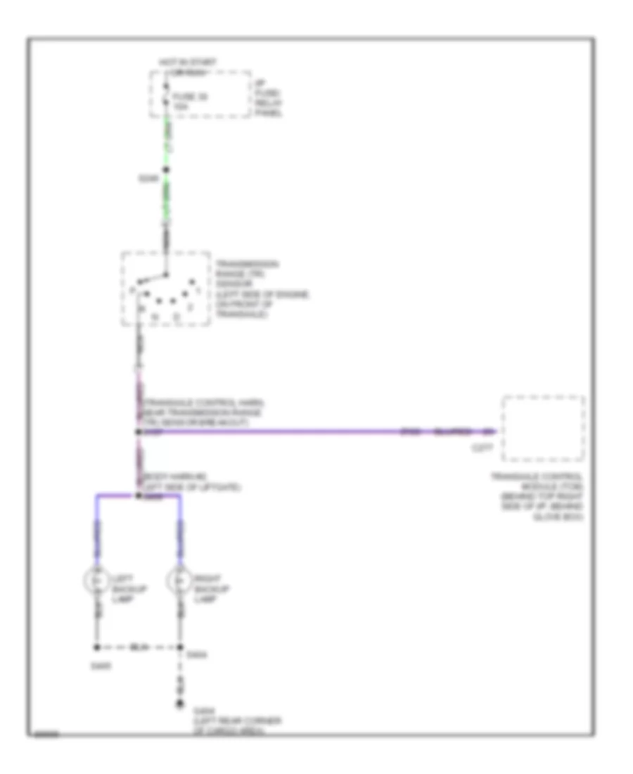
Back-up Lamps Wiring Diagram for Mercury Villager LS 1997
List of elements for Back-up Lamps Wiring Diagram for Mercury Villager LS 1997:
- (transaxle control harn, near transmission range (tr) sensor breakout) s137
- C277
- Fuse 30 10a
- G404 (left rear corner of cargo area)
- Hot in start or run
- I/p fuse/ relay panel
- Left backup lamp
- Nca
- Right backup lamp
- S246
- S404
- S405
- Transaxle control module (tcm) (behind top right side of i/p, behind glove box)
- Transmission range (tr) sensor (left side of engine, on front of transaxle)
- Zy20
Exterior Lamps Wiring Diagram (1 of 2) for Mercury Villager LS 1997
List of elements for Exterior Lamps Wiring Diagram (1 of 2) for Mercury Villager LS 1997:
- (analog)
- (electronic)
- (electronic) (analog)
- (main harn, near flasher module breakout)
- C224
- C270 c276
- C276 c270
- Cluster
- Combination switch (top of steering column)
- Flasher module (behind left side of i/p, right of steering column)
- Flasher output
- Fuse 23 10a
- Fuse 27 10a
- G103 (right rear of engine compartment, on side of strut tower)
- G200 (left kick panel)
- G410 (right rear corner of cargo area)
- Ground
- Ground distribution system
- Hazard switch (top left side of i/p, right of cluster)
- Hot at all times
- Hot in start or run
- I/p fuse/relay panel
- Ignition/battery
- Illumination lamp
- Instrument
- Interior lights system (instrument illumination)
- J/c 1 (behind left side of i/p)
- Lbe7
- Lbo3
- Lbo4
- Left
- Left front turn lamp
- Left rear turn/ hazard lamp
- Left turn indicator
- Off
- Pnk
- Right
- Right front turn lamp
- Right rear turn/ hazard lamp
- Right turn indicator
- S100
- S117
- S146 (eng harn, near eng room grommet)
- S147 (eng harn, near eng room grommet)
- S2005 (main harn, near flasher module breakout)
- S203
- S323 (body harn, above left rear wheel well)
- S324 (body harn, above left rear wheel well)
- S400
Exterior Lamps Wiring Diagram (2 of 2) for Mercury Villager LS 1997
List of elements for Exterior Lamps Wiring Diagram (2 of 2) for Mercury Villager LS 1997:
- (body harn, near trailer tow control unit breakout) s327
- (left rear of cargo area)
- (main harn, near rear vent door actuator breakout) s325
- (main harn, near speed control module breakout)
- (right "d" pillar, near roof)
- Anti-lock brake control module
- Battery
- Boo input
- Brake on/off (boo) switch (top of brake pedal support)
- C2032
- C206
- C220
- C224
- Combination switch (top of steering column)
- Cruise control module
- Engine compartment fuse/relay panel
- Engine compartment fuse/relay panel j/c 2
- Fuse 10a
- Fuse 22 15a
- G100 (front of left front fender)
- G103 (right rear of engine compartment, on side of strut tower)
- G200 (left kick panel)
- G404 (left rear corner of cargo area)
- G410 (right rear corner of cargo area)
- G998
- Ground
- Ground distribution system
- Head
- Headlamp switch
- High mount stop lamps
- Hot at all times
- I/p fuse/relay panel
- J/b fuse 100a
- J/c 1 (behind left side of i/p)
- Lb31
- Lb32
- Left front park/ cornering lamp
- Left front marker lamp
- Left license lamp
- Left rear marker lamp
- Left rear park/ stop lamp
- Left right
- Left turn in
- Left turn out
- Lq03
- Lq04
- Lq21
- Lq25
- Lq26
- Lqe1
- Nca
- Off
- Park
- Pnk
- Right front marker lamp
- Right front park/ cornering lamp
- Right license lamp
- Right rear marker lamp
- Right rear park/ stop lamp
- Rt turn in
- Rt turn out
- S100
- S117
- S124
- S125
- S126
- S2006
- S239
- S305
- S306
- S312
- S317
- S401
- S402
- S406
- S407
- S408
- S411
- Smart entry control (sec)/ timer module (behind center of i/p)
- Tail lamp cntrl
- Tail lamp relay
- Trailer tow connector (under left rear of vehicle)
- Trailer tow control unit
- W/ anti-theft
- W/ trailer option
GROUND DISTRIBUTION
Ground Distribution Wiring Diagram (1 of 3) for Mercury Villager LS 1997
List of elements for Ground Distribution Wiring Diagram (1 of 3) for Mercury Villager LS 1997:
- (engine harness, near breakout to a/c compressor clutch)
- (engine harness, near breakout to left front park/turn lamp) s105
- (engine harness, near breakout to pcm)
- (engine harness, right side of i/p) s214
- (front of left front fender)
- (i/p harness, near breakout to refresh/ recirculate door actuator)
- (i/p harness, right side of i/p)
- (left front of engine compartment)
- (left front of engine)
- (right rear of engine compartment, on strut tower)
- A/c high pressure switch
- Accessory relay
- Anti-lock brake control module
- Battery
- Brake fluid level switch
- Bulb check relay
- C134
- C135
- C136
- Camshaft position sensor
- Camshaft position sensor shield
- Cooling fan motor
- Crankshaft position sensor shield
- Data link connector #1
- Data link connector #2
- Daytime running lamps module
- Engine compartment fuse/relay panel
- Engine compartment fuse/relay panel junction connector #2
- From s202 (diagram 2 of 3)
- From s212 (diagram 3 of 3)
- Front heated oxygen sensor
- Front wiper motor assembly
- G100
- G102 (left rear of engine compartment, on side of strut tower)
- G103
- G103 (right rear of engine compartment, on side of strut tower)
- G106
- G108
- G111 (left side of engine compartment, below battery tray)
- G134 (top of engine)
- G200 (left kick panel)
- G201 (behind right side of i/p)
- Generator/ voltage regulator
- Hood switch
- I/p fuse/relay panel
- Ignition key switch
- Ignition relay
- Inhibit relay
- Knock sensor shield
- Left front marker lamp
- Left front park/ cornering lamp
- Left front turn lamp
- Left front wheel speed sensor shield
- Left headlamp
- Left headlamp relay
- Left rear wheel speed sensor shield
- Mass air flow sensor shield
- Nca
- Not used
- O/d off switch
- Outside air temperature sensor
- Power transistor
- Powertrain control module
- Rear heated oxygen (ho2s) sensor
- Rear heated oxygen sensor shield
- Resistor shield
- Right front marker lamp
- Right front park/ cornering lamp
- Right front turn lamp
- Right front wheel speed sensor shield
- Right headlamp (w/o drl)
- Right headlamp relay
- Right rear wheel speed sensor shield
- S100 (engine harness, inside engine compt relay box)
- S101 (engine harness, near breakout to right headlamp)
- S102 (engine harness, near breakout to engine oil pressure switch)
- S103 (engine harness, near breakout to right headlamp)
- S104 (engine harness, near breakout to left front park/turn lamp)
- S106
- S107 (engine harness, near breakout to wiper/washer amplifier assembly)
- S108
- S109
- S110
- S117
- S117 (engine harness, near breakout to left front park/turn lamp)
- S200 (engine harness, near breakout inertia fuel shut-off switch)
- S213 (engine harness, right rear eng compt)
- S215 (engine harness, near breakout to g201)
- S216 (engine harness, near breakout to abs module)
- S218 (engine harness, right rear of engine)
- S219 (engine harness, right rear of engine)
- S220
- S221 (engine harness, near breakout to tcm)
- S222 (engine harness, near breakout to pcm)
- S230
- Shield
- Shift lock solenoid/ park position switch
- Speed control hold relay
- Throttle position sensor shield
- To g415 (diagram 3 of 3)
- Transaxle control module
- Washer fluid level switch
- Wiper/washer amplifier assembly
Ground Distribution Wiring Diagram (2 of 3) for Mercury Villager LS 1997
List of elements for Ground Distribution Wiring Diagram (2 of 3) for Mercury Villager LS 1997:
- * analog ** electronic
- * **
- A/c
- Air bag
- Autolamp module
- Blower
- Blower motor/ speed controller
- Box lamp
- C2003
- C2030
- C2031
- C2032
- C266
- C270
- C274
- C276
- Cigar lighter
- Compressor clutch coil
- Control (iac) valve #1
- Control module
- Coolant valve solenoid
- Data link connector #1
- Diagnostic monitor
- Door jamb switch
- Door lock switch
- Eatc
- Electronic automatic
- Flasher module
- Front
- Front blower
- Front climate control panel
- Front dome lamp
- G203 (right kick panel)
- Glove
- Headlamp switch
- Idle air
- Inated visor mirror
- Instrument cluster
- Instrument panel dimmer switch
- Joint connector #1
- Key lock switch
- Left
- Left door
- Left illum-
- Lock actuator assembly
- Lock switch
- Map lamp assembly
- Master window/
- Moon
- Motor
- Motor resistor assembly
- Motor switch
- Nca
- Power antenna module
- Power mirror switch
- Power seat switch
- Power window control
- Power/ heated mirror
- Rear
- Rear blower
- Rear defogger switch
- Rear engine
- Rear radio control
- Right
- Right door
- Right illum-
- Roof relay
- S201 (body harness, near breakout to inertia fuel shut-off switch)
- S203 (i/p harness, right side of i/p)
- S204 (i/p harness, right side of i/p)
- S205 (i/p harness, center of i/p)
- S207 (i/p harness, behind right top side of i/p)
- S208 (i/p harness, behind right top side of i/p)
- S209 (i/p harness, near breakout to refresh/ recirculation door actuator)
- S210 (engine harness, near breakout to a/c compressor clutch)
- S211 (i/p harness, right side of i/p)
- S243 (i/p harness, center of i/p)
- S248 (i/p harness, center of i/p)
- S500 (body harness, near breakout to power window module)
- S501 (body harness, near breakout to power window module)
- S606
- S900 (body harness, near breakout to left illumination visor)
- S901 (body harness, near breakout to dome lamp)
- Smart entry control (sec)/timer module
- Speed
- Speed control on/off switch
- Switch (front)
- Temperature control (eatc) module
- To g200 (diagram 1 of 3)
- W/o eatc
- Wiper/ washer switch
Ground Distribution Wiring Diagram (3 of 3) for Mercury Villager LS 1997
List of elements for Ground Distribution Wiring Diagram (3 of 3) for Mercury Villager LS 1997:
- (body harness, near breakout to rear wiper motor assembly)
- (right d pillar, near roof)
- Amplifier
- Anti-theft
- Auxiliary power outlet
- Breakout to g404)
- C268
- C270
- C274
- Cd changer
- From rear wheel speed sensor shields (diagram 1 of 3)
- Front climate control panel
- Fuel pump module
- Fuel shut-off switch)
- G202 (behind left side of i/p)
- G404 (left rear corner of cargo area)
- G410 (lower right rear corner of cargo area)
- G415 (above rear axle)
- G998
- High mount stop lamps
- Inertia fuel shut-off switch
- Instrument cluster
- Instrument cluster (analog)
- Lamp
- Left backup lamp
- Left license lamp
- Left lumbar pump motor
- Left power seat switch
- Left rear marker lamp
- Left rear park/ stop lamp
- Left rear turn/ hazard lamp
- Liftgate key lock switch
- Liftgate latch switch assembly
- Liftgate lock actuator assembly
- Nca
- Opening liftgate glass switch
- Radio
- Rear blower motor switch relay
- Rear climate control panel (w/ eatc)
- Rear climate control panel (w/o eatc)
- Rear radio control
- Rear wiper motor assembly
- Rear wiper/ washer amplifier
- Right backup lamp
- Right license lamp
- Right rear marker lamp
- Right rear park/ stop lamp
- Right rear turn/ hazard
- S212
- S229 (i/p harness, center of i/p)
- S301 (body harness, near breakout to rear vent door actuator)
- S302 (body harness, near breakout to rear vent door actuator)
- S304 (body harness, near breakout to rear blower motor switch relay)
- S306 (body harness, near breakout to g404)
- S319 (body harness, driver's seat p/a harness)
- S320 (i/p harness, near breakout to rear radio control unit)
- S336 (body harness, near breakout to left rear speaker)
- S400 (body harness, near breakout to g410)
- S401 (body harness, near breakout to g410)
- S404
- S405 (body harness, near breakout to rear wiper motor assembly)
- S410 (body harness, near breakout to g410)
- S411 (body harness, near breakout to rear wiper motor assembly)
- Seat belt switch
- Subwoofer amplifier
- To g200 (diagram 1 of 3)
- Trailer tow connector
- Trailer tow control unit
- Vehicle speed sensor
- W/ analog cluster
- W/ electronic cluster
- W/o
- With anti-theft & fixed glass
- With anti-theft & moveable liftgate glass
HEADLIGHTS
Headlight Wiring Diagram, with Autolamps for Mercury Villager LS 1997
List of elements for Headlight Wiring Diagram, with Autolamps for Mercury Villager LS 1997:
- (analog)
- (electronic)
- (eng compt harn, near comb sw breakout)
- (eng compt harn, near intake air temp sensor breakout)
- (eng compt harn, near left headlamp breakout)
- (eng compt harn, near right front turn lamp breakout)
- (eng compt harn, near right headlamp breakout)
- (front of left front fender)
- 100k ohm
- 3.3k ohm
- A/light (h/l) relay (right side of engine compt, in right engine compartment relay block)
- Autolamp ctrl
- Autolamp module (behind top right side of i/p)
- Autolamp on input
- Autolamp sensor (top right side of i/p, near windshield)
- Battery
- C133
- C135
- C266
- C276
- Combination switch
- Daytime running lamps (drl) module (right side of engine compartment, on front of strut tower)
- Delayed exit input
- Delayed exit rehostat
- Engine compartment fuse/relay panel
- Flash-to-pass
- Fuse 7.5a
- G100
- G200 (left kick panel)
- Ground
- H/l l fuse 15a
- H/l r fuse 15a
- Head
- Headlamp control c2031
- Headlamp switch
- High beam
- High beam indicator
- Hot at all times
- Hot in run
- I/p fuse/ relay panel
- Ign
- Instrument cluster
- Instrument panel dimmer switch
- J/c 1 (behind left side of i/p)
- Left headlamp
- Left headlamp relay (in engine compartment relay box)
- Lx01
- Lx02
- Lx03
- Lx04
- Lx05
- Lx06
- Lx07
- Lxe8
- Off
- Off/on control
- Park
- Pr02
- Pr06
- Pr07
- Pr08
- Pr09
- Ref ctrl
- Right headlamp
- Right headlamp relay (in engine compartment fuse/relay panel)
- S101
- S104
- S111
- S113
- S117
- S123
- S142
- S143
- S144
- S145
- S148
- S148 (eng compt harn, near right headlamp breakout)
- S149
- S150
- S203
- S223
- S225
- S249
- S297
- Sensor input
- Smart entry control (sec)/ timer module (behind center of i/p)
- W/ anti- theft
- W/ drl
- W/ drl only
- W/o drl
Headlight Wiring Diagram, with DRL for Mercury Villager LS 1997
List of elements for Headlight Wiring Diagram, with DRL for Mercury Villager LS 1997:
- (analog)
- (electronic)
- (eng compt harn, near comb sw breakout)
- (eng compt harn, near intake air temp sensor breakout)
- (eng compt harn, near left headlamp breakout)
- (eng compt harn, near right front turn lamp breakout)
- (eng compt harn, near right headlamp breakout)
- (eng compt, harn behind right side of i/p)
- (front of left front fender)
- (main harn, behind right side of i/p)
- Autolamps circuit
- Battery
- Brake fluid level switch (left rear of engine compartment, on brake fluid reservoir)
- Brake warning indicator
- C266
- C268
- C276
- Ci33
- Ci35
- Combination switch
- Daytime running lamps (drl) module (right side of engine compartment, on front of strut tower)
- Engine compartment fuse/relay panel
- Engine compartment fuse/relay panel junction connector #2
- Flash-to-pass
- Fuse 10a
- Fuse 7.5a
- G100
- G103 (right rear of engine compartment, on side of strut tower)
- G200 (left kick panel)
- Gen input
- Generator/ voltage regulator (lower right front of engine)
- Gnd
- H/l l fuse 15a
- H/l r fuse 15a
- Head
- Headlamp switch
- High beam
- High beam indicator
- High beam on in
- Hot at all times
- Hot in start
- Hot in start or run
- I/p fuse relay panel
- I/p fuse/ relay panel
- Ign input
- Instru- ment cluster
- Instrument cluster
- J/c 2 (behind left side of i/p)
- Left hdlp ctrl
- Left headlamp
- Left headlamp relay (in engine compartment relay box)
- Lights on input
- Off
- Park
- Park bk sw in
- Park brake switch (on park brake assembly)
- Pr01
- Pr02
- Pr03
- Pr04
- Pr05
- Pr06
- Pr07
- Pr08
- Pr09
- Pr11
- Pr12
- Pre1
- Right hdlp ctrl
- Right headlamp
- Right headlamp relay (in engine compartment fuse/relay panel)
- S100
- S101
- S105
- S111
- S113
- S117
- S123
- S141
- S142
- S143
- S144
- S145
- S148
- S149
- S150
- S200
- S223
- S225
- S238
- S245
- S291
- S292
- S297
- Start input
- W/ auto- lamps only
- W/ autolamps only
Headlight Wiring Diagram, without DRL for Mercury Villager LS 1997
List of elements for Headlight Wiring Diagram, without DRL for Mercury Villager LS 1997:
- (analog)
- (electronic)
- (eng compt harn, near intake air temp sensor breakout)
- (eng compt harn, near left headlamp breakout)
- (eng compt harn, near right headlamp breakout) s148
- C266
- C276
- Combination switch
- Engine compartment fuse/relay panel
- Flash-to-pass
- G100 (front of left front fender)
- G200 (left kick panel)
- H/l l fuse 15a
- H/l r fuse 15a
- Head
- Headlamp switch
- High beam
- High beam indicator
- Hot at all times
- Instrument cluster
- J/c 1 (behind left side of i/p)
- Left headlamp
- Left headlamp relay (in engine compartment relay box)
- Off
- Park
- Right headlamp
- Right headlamp relay (in engine compartment fuse/relay panel)
- S101
- S104
- S117
- S123
- S142
- S145
- S149
- S203
- S223
- S225
- S297 (eng compt harn, near comb sw breakout)
HORN
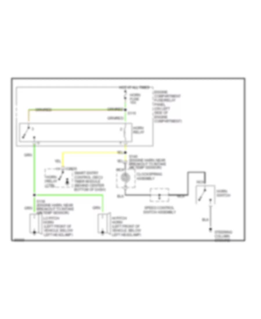
Horn Wiring Diagram for Mercury Villager LS 1997
List of elements for Horn Wiring Diagram for Mercury Villager LS 1997:
- C2030
- Clockspring assembly
- Engine compartment fuse/relay panel (on left side of engine compartment)
- Hi pitch horn (left front of vehicle, below left headlamp)
- Horn fuse 15a
- Horn relay
- Horn relay ctrl
- Horn switch
- Hot at all times
- Lo pitch horn (left front of vehicle, below left headlamp)
- Nca
- S115
- S139 (engine harn, near breakout to intake air temp sensor)
- S140 (engine harn, near breakout to intake air temp sensor)
- Smart entry control (sec)/ timer module (behind center bottom of dash)
- Speed control switch assembly
- Steering column ground
INSTRUMENT CLUSTER
Analog Cluster Wiring Diagram (1 of 2) for Mercury Villager LS 1997
List of elements for Analog Cluster Wiring Diagram (1 of 2) for Mercury Villager LS 1997:
- (above rear axle)
- (behind left side of i/p)
- (behind top left side of i/p, taped to main harness)
- (left kick panel)
- (main harn, behind center of i/p)
- 10a
- 10b
- 10c
- 11b
- 11c
- 12b
- 12c
- 2 pole speed sensor
- 56 ohms
- Air bag diagnostic monitor (behind left side of i/p)
- Air bag ind.
- Anti- slosh module
- Anti-lock warning ind.
- Av02
- Av32
- Brake warning ind.
- C266
- C268
- C270
- Charge warning ind.
- Coolant temp.
- Coolant temperature sender (top right rear of engine)
- Cruise ind.
- Door ajar ind.
- Ej07
- Ej10
- Ej17
- Engine coolant temp. gauge
- Engine oil pressure switch (lower right front of engine, near oil filter)
- Engine speed
- Exterior lights system (hazard switch & combination switch)
- Fuel gauge
- Fuel gauge sender
- Fuel level
- Fuel pump module (below rear of vehicle, inside fuel tank)
- Fuse 10a
- G200
- G202
- G415
- Gnd
- Headlights system (combination switch)
- Hi beam ind.
- Hot in start or run
- I/p fuse/ relay panel
- Ign
- Illum. dim
- Illum. lamps
- Illum. power
- Instrument cluster
- J/c 1
- Left turn ind.
- Low fuel warning ind.
- Low oil press. ind.
- Low washer fluid ind.
- Malfunction ind.
- Nca
- Nr01
- O/d off ind.
- Pnk
- Powertrain control module (pcm) (behind top right side of i/p, behind glove box)
- Prndl illum. dim
- Prndl illum. lamp
- Prndl illum. pwr
- Ps15
- Red
- Right turn ind.
- S203
- S229
- S254
- S255 (main harn, near instrument cluster)
- S257 (main harn, behind center of i/p)
- S259
- S260
- S262
- S283
- S302
- Seat belt warning ind.
- Smart entry control (sec)/timer module (behind center of i/p)
- Speed control module (below center of i/p, mounted on center i/p brace support)
- Speedometer
- Tachometer
- Transaxle control module (tcm) (behind top right side of i/p, behind glove box)
- V ref
- Vehicle speed in
- Vehicle speed out
- Vehicle speed sensor (left side of engine, on rear of transaxle)
- Zy03
- Zy24
- Zy27
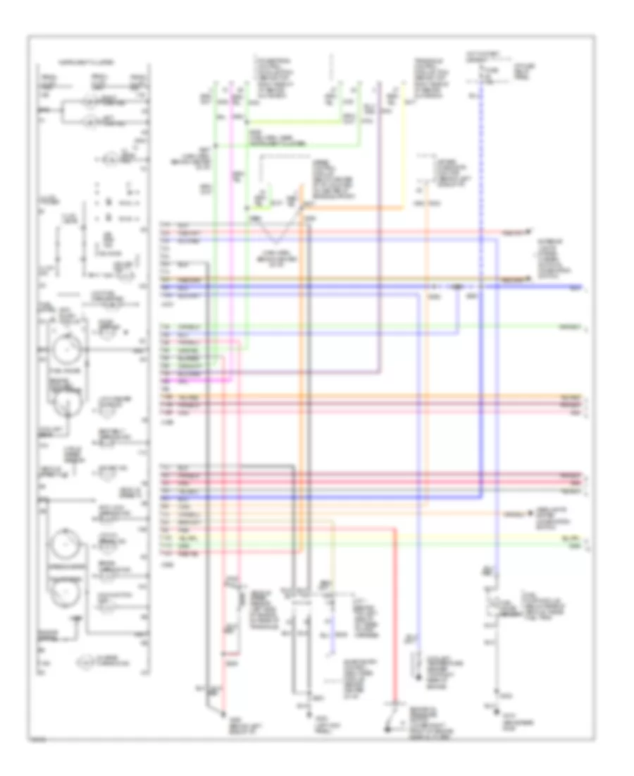
Analog Cluster Wiring Diagram (2 of 2) for Mercury Villager LS 1997
List of elements for Analog Cluster Wiring Diagram (2 of 2) for Mercury Villager LS 1997:
- (below center of i/p, mounted on center i/p support brace)
- (engine compt harn, behind right side of i/p) s286
- (engine compt harn, near breakout to iat sensor)
- (front of left front fender)
- (left kick panel)
- (left rear of engine compt, on brake fluid reservoir)
- (lower right front of engine compt, on washer fluid reservoir)
- (main harn, right side of i/p) s292
- (on park brake assembly)
- (right rear of engine compt, on side of strut tower)
- Anti-lock brake control module
- Brake fluid level switch
- Bulb check relay
- C133
- C135
- Daytime running lamps module (right side of engine compt, on front of strut tower)
- Engine compartment fuse/relay panel
- Engine compartment fuse/relay panel j/c 1
- Engine compartment fuse/relay panel j/c 2
- Fuse 7.5a
- G100
- G103
- G200
- Generator/ voltage regulator (lower right front of engine)
- Head
- Headlamp switch
- Hot at all times
- Hydraulic actuator assembly (right front of engine compt)
- I/p fuse/ relay panel
- Interior lights system (instrument illumination)
- J/c 1 (behind left side of i/p, taped to main harness)
- J/c 2 (behind top left side of i/p, right of instrument cluster)
- J/c 2 (behind top left side of i/p, taped to main harness)
- Jc11
- Nca
- Off
- Park
- Park brake switch
- Pnk
- S100
- S105
- S141
- S203
- S256
- S291 (main harn, right side of i/p)
- S293 (main harn, center of i/p)
- S294 (main harn, center of i/p)
- S300
- Seat belt switch (near left front seat belt buckle)
- Smart entry control (sec)/ timer module (behind center of i/p)
- Tail lamp relay
- W/ drl
- Washer fluid level switch
Electronic Cluster Wiring Diagram (1 of 2) for Mercury Villager LS 1997
List of elements for Electronic Cluster Wiring Diagram (1 of 2) for Mercury Villager LS 1997:
- (behind center of i/p) s283
- (behind left side of i/p)
- (below rear of vehicle, inside fuel tank)
- (left kick panel)
- (left rear of engine compt, on side of strut tower)
- (main harn, behind center of i/p)
- (main harn, near breakout to eatc module)
- (main harn, near inst cluster)
- 10a
- 10b
- 10c
- 11a
- 11b
- 11c
- 12a
- 12b
- 12c
- 13a
- 13c
- 14a
- 14c
- 15a
- 15c
- 16c
- 17c
- 18c
- 19c
- 20c
- Air bag diagnostic monitor (behind left side of i/p)
- Air bag ind.
- Anti-lock warning ind.
- Av02
- Av05
- Av32
- Bat
- Brake warning ind.
- Bs29
- C20
- C2029
- C272
- C274
- C276
- Charge warning ind.
- Coolant temp input
- Coolant temperature sender (top right rear of engine)
- Cruise control on input
- Data input-fuel flow
- Digital display
- Dimmer output
- Door ajar ind.
- Ej07
- Ej10
- Ej17
- Electronic automatic temperature control (eatc) module (behind center of i/p)
- Eng/met
- Engine oil pressure switch (lower right front of engine, near oil filter)
- Exterior lights system (hazard switch & combination switch)
- Fuel computer reset
- Fuel computer select
- Fuel computer trip/reset
- Fuel computer trip/select
- Fuel gauge sender
- Fuel level input
- Fuel pump module
- Fuse 10a
- G102
- G200
- G202
- G415 (above rear axle)
- Gnd
- Grd
- Headlights system (combination switch)
- Hi beam ind.
- Hot at all times
- Hot in start or run
- I/p fuse/ relay panel
- Ig01
- Ig91
- Ig92
- Ign
- Illum dim input
- Instrument cluster
- J/c 1 (behind top left side of i/p, taped to main harness)
- La03
- Lb15
- Lb16
- Left turn ind.
- Low fuel ind ctrl
- Low fuel warning ind.
- Low oil level ind.
- Low oil press. ind.
- Low washer fluid ind.
- Ma01
- Ma02
- Ma03
- Ma04
- Ma06
- Ma07
- Ma11
- Ma12
- Ma14
- Ma15
- Ma16
- Ma17
- Ma41
- Mae1
- Mae2
- Malfunction ind.
- Md01
- Mj01
- Mje2
- Nb01
- Nca
- Nf01
- Ni03
- Nm01
- Nn01
- Nr01
- O/d off ind.
- O/s temp sensor input
- Outside air temperature sensor (lower center front of vehicle, below front bumper)
- Pnk
- Powertrain control module (pcm) (behind top right side of i/p, behind glove box)
- Prndl illum. dim
- Prndl illum. lamp
- Prndl illum. pwr
- Ps15
- Red
- Right turn ind.
- S103
- S2011
- S203
- S229
- S232
- S254
- S255
- S257 (main harn, behind center of i/p)
- S259
- S260
- S262
- S302
- Seat belt warning ind.
- Smart entry control (sec)/ timer module (behind center of i/p)
- Speed control module (mounted on center i/p brace support)
- Start input
- Tachometer input
- Transaxle control module (tcm) (behind top right side of i/p, behind glove box)
- Vehicle speed sensor (left side of engine, on rear of transaxle)
- Vss grd
- Vss input
- Vss ouput
- Zy03
- Zy24
- Zy27
Electronic Cluster Wiring Diagram (2 of 2) for Mercury Villager LS 1997
List of elements for Electronic Cluster Wiring Diagram (2 of 2) for Mercury Villager LS 1997:
- (below center of i/p, mounted on center i/p support brace)
- (engine compt harn, near breakout to iat sensor)
- (front of left front fender)
- (left kick panel)
- (left rear of engine compt, on brake fluid reservoir)
- (lower right front of engine compt, on washer fluid reservoir)
- (main harn, right side of i/p) s292
- (on park brake assembly)
- (right rear of engine compt, on side of strut tower)
- Anti-lock brake control module
- Brake fluid level switch
- Bulb check relay
- C133
- C135
- Daytime running lamps module (right side of engine compt, on front of strut tower)
- Engine compartment fuse/relay panel
- Engine compartment fuse/relay panel j/c 1
- Engine compartment fuse/relay panel j/c 2
- English/ metric
- Fuel computer control panel (left of steering column)
- Fuse 7.5a
- G100
- G103
- G200
- Generator/ voltage regulator (lower right front of engine)
- Head
- Headlamp switch
- Hot at all times
- Hydraulic actuator assembly (right front of engine compt)
- I/p fuse/ relay panel
- Illum.
- Interior lights system (instrument illumination)
- J/c 1 (behind left side of i/p, taped to main harness)
- J/c 2 (behind top left side of i/p, right of instrument cluster)
- J/c 2 (behind top left side of i/p, taped to main harness)
- Jc11
- Nca
- Of i/p)
- Off
- Park
- Park brake switch
- Pnk
- Reset
- S100
- S105
- S141
- S203
- S256
- S286 (engine compt harn, behind right side of i/p)
- S291 (main harn, right side of i/p)
- S294 (main harn, center of i/p)
- S300
- Seat belt switch (near left front seat belt buckle)
- Select
- Smart entry control (sec)/ timer module (behind center of i/p)
- Tail lamp relay
- Trip reset
- Trip select
- W/ drl
- Washer fluid level switch
INTERIOR LIGHTS
Courtesy Lamps Wiring Diagram for Mercury Villager LS 1997
List of elements for Courtesy Lamps Wiring Diagram for Mercury Villager LS 1997:
- (behind top left side of i/p)
- (room lamp harn, near base of "a" pillar)
- * electronic
- C2030
- C2032
- C266 c274
- Cluster
- Courtesy lamp control
- Courtesy lamps control
- Door
- Door ajar ind
- Door switch input
- Front dome lamp
- Fuse 15a
- G200 (left kick panel)
- G404 (left rear corner of cargo area)
- Glove box lamp
- Hot at all times
- I/p fuse/relay panel
- Instrument cluster
- J/c 1
- J/c 1 (behind top left side of i/p)
- J/c 3 (behind top left side of i/p)
- Left door jamb switch
- Left door panel lamp
- Left foot lamp assembly
- Left illuminated visor mirror
- Left map lamp
- Left map lamp switch
- Li70
- Li91
- Liftgate lamp
- Liftgate latch switch assembly
- Liftgate open input
- Map lamp assembly
- Nca
- Off
- Rear dome lamp
- Rear lamps control
- Rear reading lamp
- Red li87
- Red/ li89
- Right door jamb switch
- Right door panel lamp
- Right foot lamp assembly
- Right illuminated visor mirror
- Right map lamp
- Right map lamp switch
- S2000 (main harn, behind right side of i/p)
- S2001 (main harn, behind right side of i/p)
- S2002 (main harn, behind top left side of i/p)
- S203
- S276 (main harn, behind center of i/p)
- S402
- S901
- S902 (room lamp harn, near base of "a" pillar)
- S904
- S907
- S908
- S909
- Sliding door ajar switch
- Sliding door step lamp
- Smart entry control (sec)/ timer module (behind center of i/p)
Instrument Illumination Wiring Diagram for Mercury Villager LS 1997
List of elements for Instrument Illumination Wiring Diagram for Mercury Villager LS 1997:
- (2) bulbs
- (4) bulbs
- (analog)
- (behind center of i/p)
- (electronic)
- Anti-theft system (smart entry control (sec)/ timer module)
- Ashtray lamp
- Autolamp control module
- Brighter
- C201
- C2028
- C2030
- C266
- C268
- C274
- C276
- Cigar lighter illumination
- Darker
- Dimming control
- Diode
- Electronic automatic temperature control (eatc) module
- Front climate control panel
- Fuel computer control panel
- Fuse 10a
- Fuse 7.5a
- G200 (left kick panel)
- Hazard switch
- Head
- Headlamp switch
- Hot at all times
- Hot in acc or run
- I/p fuse/ relay panel
- Instrument cluster
- Instrument panel dimmer switch
- Ip01
- J/c 1 (behind top left side of i/p)
- J/c 1 (behind top left side of i/p)
- J/c 2 (behind top left side of i/p, right of instrument cluster)
- J/c 3 (behind top left side of i/p, right of instrument cluster)
- Master window/ door lock switch
- Panel lamps "bright" input
- Panel lamps "dark" input
- Park
- Pnk
- Power mirror switch
- Prndl illum
- Radio
- Rear blower motor switch (front)
- Rear climate control panel
- Rear defogger switch
- Rear radio control
- Rear wiper/ washer switch
- Right door lock switch
- Right power window switch
- S203
- S256 (main harn, near joint connector #2 breakout)
- S279
- S601 (left front door harn, near top of right cowl panel)
- S602 (left front door harn, near top of right cowl panel)
- Smart entry control (sec)/ timer module
- Speed control on/off switch
- Tail lamp relay
- W/analog cluster
- W/eatc
- W/electronic cluster
- W/o eatc
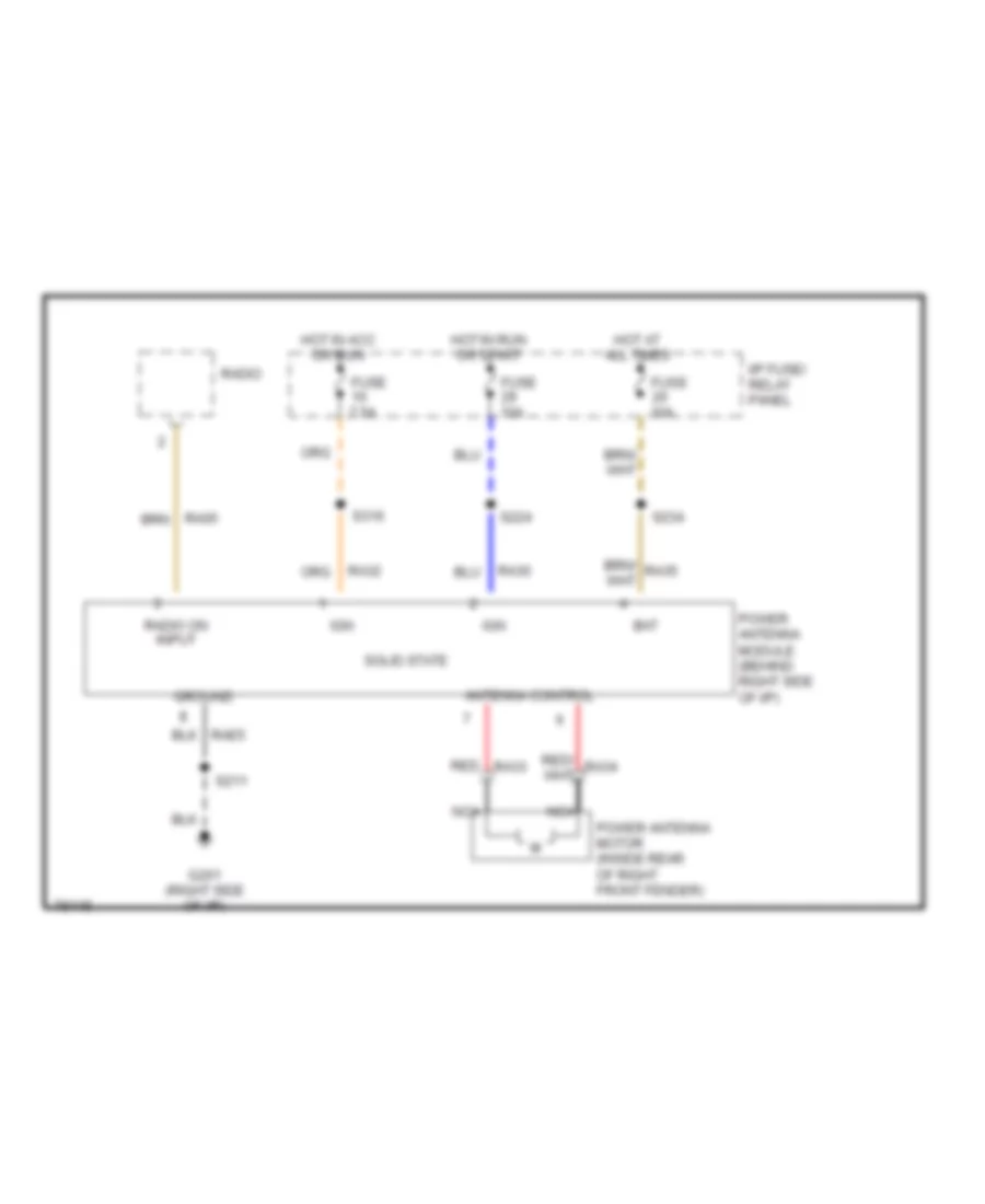
POWER ANTENNA
Power Antenna Wiring Diagram for Mercury Villager LS 1997
List of elements for Power Antenna Wiring Diagram for Mercury Villager LS 1997:
- Antenna control
- Bat
- Fuse 10a
- Fuse 7.5a
- G201 (right side of i/p)
- Ground
- Hot at all times
- Hot in acc or run
- Hot in run or start
- I/p fuse/ relay panel
- Ign
- Nca
- Power antenna module (behind right side of i/p)
- Power antenna motor (inside rear of right front fender)
- Ra30
- Ra32
- Radio
- Radio on input
- Red ra33
- S211
- S224
- S234
- S316
- Solid state
POWER DISTRIBUTION
Power Distribution Wiring Diagram (1 of 4) for Mercury Villager LS 1997
List of elements for Power Distribution Wiring Diagram (1 of 4) for Mercury Villager LS 1997:
- (body harness, left seat jumper harness) s307
- (engine harness, in engine compt fuse/relay panel) s115
- (engine harness, near breakout to anti-theft relay) s133
- (engine harness, near breakout to conn c106 pcm relay) s112
- (engine harness, near breakout to conn c196 intake air temp sensor) s111
- (engine harness, near breakout to conn c242 in-line circuit breaker #1) s226
- (engine harness, near breakout to grommet to interior of vehicle)
- (engine harness, near breakout to injector #1) s114
- (engine harness, near breakout to injector #1) s118
- (engine harness, near grommet to engine compt) s123
- (i/p harness, near breakout to in-line conn c255m, right side of i/p) s227
- A/light (h/l) relay
- Abs fuse 20a
- Abs fuse 30a
- Alt fuse 10a
- Alt fuse 120a
- Anti-theft relay
- Autolamp module
- Battery
- Breakout to j/c 2) s225
- C2032
- C275
- Combination switch
- Cooling fan hi 1 relay
- Cooling fan hi 2 relay
- Cooling fan lo relay
- Data link connector #1
- Daytime running lamps (drl) module
- Eecs fuse 10a
- Engine compartment fuse/relay panel
- Engine compartment relay box
- Fuel injector #1
- Fuel injector #2
- Fuel injector #3
- Fuel injector #4
- Fuel injector #5
- Fuel injector #6
- Generator/ voltage regulator
- H/l l fuse 15a
- H/l r fuse 15a
- Headlamp switch
- Horn fuse 15a
- Horn relay
- Hydraulic actuator assembly
- Ign fuse 30a
- Inj fuse 10a
- Inline circuit breaker #1
- Inline circuit breaker #2
- Insp l fuse 15a
- Left lumbar seat switch
- Left power seat switch
- Nca
- Not used
- P/w fuse 30a
- Power window relay
- Powertrain control module (pcm)
- Powertrain control module (pcm) relay
- Rad fuse 65a
- Red
- Right power seat switch
- S113
- S129 (engine harness, near breakout to in-line conn c118m, left side of engine)
- S2012 (i/p harness, near breakout to in-line conn c2021m, left side of i/p)
- S223
- S228 (i/p harness, near breakout to conn c242, behind left side of i/p)
- Sec fuse 7.5a
- Smart entry control (sec)/timer module
- Starter assembly
- To def fuse (engine compartment fuse/relay panel) (diagram 3 of 4)
- To ignition switch (diagram 2 of 4)
- To j/b fuse (engine compartment fuse/relay panel) (diagram 2 of 4)
Power Distribution Wiring Diagram (2 of 4) for Mercury Villager LS 1997
List of elements for Power Distribution Wiring Diagram (2 of 4) for Mercury Villager LS 1997:
- (body harness, breakout to conn c254 power mirror switch) s279
- (engine harness, near breakout to conn c152 ignition coil) s120
- (engine harness, near breakout to conn c20204m, on anti-theft indicator) s241
- (i/p harness, near breakout to conn c2011 j/c #2) s250
- (i/p harness, near breakout to in-line conn c2021m, center of i/p) s2013
- (i/p harness, near breakout to in-line conn c255m, right side of i/p) s242
- A/c relay
- Acc
- Accessory relay
- Air bag diagnostic monitor
- Autolamp module
- Auxiliary power outlet
- Blw fuse 65a
- C202
- C2032
- C204
- C206
- C275
- Cigar lighter
- Condenser
- Daytime running lamps (drl) module
- Electronic automatic temperature control (eatc) assembly
- Engine compartment fuse/relay panel
- Engine compartment relay box
- Exhaust gas recirculation (egr) valve
- F pump fuse 15a
- From engine compartment c fuse/relay panel (diagram 1 of 4)
- From ign fuse (engine compartment fuse/relay panel) (diagram 1 of 4)
- Front blower motor
- Front blower motor/ speed controller
- Front blower relay
- Front climate control panel
- Front heated oxygen sensor
- Front washer motor
- Front wiper motor assembly
- Front wiper/ washer amplifier assembly
- Fuel pump relay
- Fuse 10a
- Fuse 20a
- Fuse 7.5a
- G200 (left kick panel)
- I/p fuse/ relay panel
- Idle air control (iac) valve #2
- Ignition coil
- Ignition relay
- Ignition switch
- Inhibit relay
- J/b fuse 100a
- Nca
- Nca (engine harness, near breakout to conn c202 engine compt fuse/relay panel) s119
- Off
- Power mirror switch
- Powertrain control module (pcm)
- Rear climate control panel
- Rear heated oxygen sensor
- Rear washer motor
- Rear wiper motor assembly
- Rear wiper/ washer amplifier
- Red
- Run
- S127
- S205
- S236 (i/p harness, near breakout to conn c256 front blower motor)
- S249 (i/p harness, near breakout to in-line conn c255m, right side of i/p)
- Smart entry control (sec)/ timer module
- Start
- Throttle position (tp) switch
- To fuse 10 (i/p fuse/ relay panel) (diagram 4 of 4)
- To fuse 27 (i/p fuse/ relay panel) (diagram 4 of 4)
- To liftgate defroster relay (i/p fuse/ relay panel) (diagram 3 of 4)
- To tail lamp relay (i/p fuse/ relay panel) (diagram 3 of 4)
- W/ eatc
- W/o eatc
Power Distribution Wiring Diagram (3 of 4) for Mercury Villager LS 1997
List of elements for Power Distribution Wiring Diagram (3 of 4) for Mercury Villager LS 1997:
- (body harness, near breakout to conn c328, rear vent door actuator) s317
- (body harness, near breakout to in-line conn c332m, left left wheel well) s406
- (engine harness, near breakout to conn c196 intake air temp sensor) s124
- (engine harness, near grommet to interior) s125
- (i/p harness, near breakout to i/p) s255
- (moveable liftgate)
- C202
- Combination switch
- Def fuse 45a
- Engine compartment fuse/relay panel
- From engine compartment fuse/relay panel (diagram 1 of 4)
- From i/p fuse/relay panel (diagram 2 of 4)
- Fuse 10a
- Fuse 15a
- Fuse 20a
- Fuse 7.5a
- Headlamp switch
- I/p fuse/ relay panel
- Interior lamps system (instrument illumination)
- Left front marker lamp
- Left front park/ cornering lamp
- Left license lamp
- Left power/ heated mirror
- Left rear marker lamp
- Left rear park/ stop lamp
- Liftgate defroster grid
- Liftgate defroster relay
- Nca
- Pnk
- Rear blower motor
- Rear blower motor relay
- Rear defogger switch
- Right front marker lamp
- Right front park/ cornering lamp
- Right license lamp
- Right power/ heated mirror
- Right rear marker lamp
- Right rear park/ stop lamp
- S126 (engine harness, near breakout to conn c117 generator/voltage regulator)
- S252 (i/p harness, near breakout to in-line conn c255m, right side of i/p)
- S337 (body harness, near breakout to g411)
- S407
- S408 (body harness, near breakout to in-line conn c367m, left rear side of vehicle)
- Tail lamp relay
- To fuse 2 (i/p fuse/ relay panel (diagram 4 of 4)
- Trailer tow connector
- W/ eatc
- W/o eatc
Power Distribution Wiring Diagram (4 of 4) for Mercury Villager LS 1997
List of elements for Power Distribution Wiring Diagram (4 of 4) for Mercury Villager LS 1997:
- (body harness, near breakout to conn c246 inertia cutoff switch)
- (body harness, near breakout to conn c318, rear blower motor assembly) s213
- (body harness, near breakout to conn c361 trailer tow control unit)
- (body harness, near breakout to in-line conn c238f, left "a" pillar)
- (engine harness, near breakout to conn c161 trans range sensor)
- (i/p harness, near breakout to conn c2024f, right side of i/p) s224
- (i/p harness, near breakout to conn c263, right side of i/p) s316
- (i/p harness, near breakout to conn c276 i/p) s259
- (i/p harness, near breakout to in-line conn c2021m, center of i/p) s234
- (i/p harness, near breakout to in-line conn c2021m, center of i/p) s258
- (i/p harness, near breakout to in-line conn c2021m, center of i/p) s296
- (i/p harness, near breakout to in-line conn c255m, right side of i/p)
- (not used)
- * electronic cluster
- A/c relay
- Amplifier
- Anti-lock brake (abs) control module
- Anti-theft indicator
- Brake on/off (boo) switch
- Bulb check relay
- C2032
- C266
- C268
- C270
- C272
- C274
- C276
- Cd changer
- Cooling fan h1 relay
- Cooling fan h2 relay
- Cooling fan lo relay
- Data link connector #2
- Data link connector (dlc)
- Daytime running lamps (drl) module
- Electronic automatic temperature control (eatc) module
- Engine compartment fuse/relay panel
- Engine compartment fuse/relay panel junction connector #1
- Engine compartment relay box
- From i/p fuse/ relay panel (diagram 2 of 4)
- From i/p fuse/ relay panel (diagram 3 of 4)
- From ignition relay (i/p fuse/ relay panel) (diagram 2 of 4)
- Front climate control panel
- Front dome lamp
- Fuel computer control panel
- Fuel pump relay
- Fuse 10a
- Fuse 15a
- Fuse 20a
- Fuse 7.5a
- Glove box lamp
- Hazard switch
- I/p fuse/ relay panel
- Idle air control valve relay
- Instrument cluster
- Instrument cluster (electronic)
- Joint connector #3
- Left door panel lamp
- Left foot lamp assembly
- Left illuminated visor mirror
- Liftgate lamp
- Map lamp assembly
- Nca
- Power antenna module
- Radio
- Rear blower motor relay
- Rear blower motor switch relay
- Rear dome lamp
- Rear radio control
- Rear reading lamp
- Rear wiper motor assembly
- Right door panel lamp
- Right foot lamp assembly
- Right illuminated visor mirror
- S200
- S231
- S232
- S239 (body harness, near breakout to conn c254 power mirror switch)
- S245
- S2621
- S312
- S902
- S904
- Sliding door step lamp
- Smart entry control (sec)/ timer module
- Speed control disengage switch
- Speed control hold relay
- Speed control on/off switch
- Subwoofer amplifier
- Trailer tow control unit
- Transaxle control module
- Transaxle control module (tcm)
- Transmission range (tr) sensor
- W/ eatc
- W/o eatc
- Warning chime
POWER DOOR LOCKS
Door Lock Wiring Diagram for Mercury Villager LS 1997
List of elements for Door Lock Wiring Diagram for Mercury Villager LS 1997:
- (behind left side of i/p)
- (in rear of left door)
- (instrument illumination)
- (main harn, near breakout to 12 pin conn, behind center of i/p) s276
- (not used)
- All doors lk cntl
- Battery
- C2032
- C311
- C329
- Closed
- Door open in
- Door unlk cntl
- Engine compartment fuse/relay panel
- G200 (left kick panel)
- G203 (right kick panel)
- G404 (left rear corner of cargo area)
- Ground
- Hot at all times
- Inline circuit breaker #1
- Inline circuit breaker #2
- Interior lights
- Interior lights system (instrument illumination)
- Left door jamb switch (lower front of left "b" pillar)
- Left door lock actuator assembly
- Lftgate open in
- Lftgate unlk cntl
- Li87
- Li89
- Li90
- Li94
- Liftgate latch switch assembly (lower center of liftgate)
- Liftgate lock actuator assembly
- Lock
- Lock input
- Lock/unlock in
- Master window/ door lock switch
- Nca
- Open
- P/w fuse 30a
- Ph10
- Ph19
- Ph32
- Ph35
- Ph38
- Ph43
- Pnk
- Power window relay
- Red
- Right door lock switch
- Right door jamb switch (lower front of right "b" pillar)
- Right door lock actuator assembly (in rear of right door)
- S201
- S2018 (main harn, near breakout to joint connector # 1)
- S2019 (main harn, near breakout to joint connector # 1)
- S206
- S226
- S227
- S267 (main harn, near breakout to 12 pin conn, behind center of i/p)
- S268 (main harn, near breakout to 12 pin conn, behind center of i/p)
- S274 (main harn, near breakout to 12 pin conn, behind center of i/p)
- S275 (main harn, near breakout to 16 pin conn, behind top right side of i/p)
- S333 (sliding door harn, near breakout to door contact)
- S334 (sliding door harn, near breakout to door contact)
- S403
- S501
- S600
- Sc11
- Sc15
- Sc16
- Sce2
- Sliding door ajar switch (lower rear of right "b" pillar)
- Sliding door contact switch (in rear of right "b" pillar)
- Sliding door lock actuator
- Smart entry control (sec)/ timer module (behind center of i/p)
- System
- Unlock
- Unlock input
Keyless Entry Wiring Diagram for Mercury Villager LS 1997
List of elements for Keyless Entry Wiring Diagram for Mercury Villager LS 1997:
- (behind left side of i/p)
- (in rear of left door)
- (instrument illumination)
- (main harn, near breakout to 12 pin conn, behind center of i/p) s268
- (main harn, near breakout to 12 pin conn, behind center of i/p) s276
- (main harn, near breakout to joint connector # 1) s2018
- All doors lk cntl
- Anti-theft system
- Battery
- Breaker #1
- Breaker #2
- C2030
- C2032
- C311
- C329
- Closed
- Door open in
- Door unlk cntl
- Engine compartment fuse/relay panel
- Er05
- Er10
- Fuse 10a
- G100 (front of left front fender)
- G200 (left kick panel)
- G203 (right kick
- G203 (right kick panel)
- G404 (left rear corner of cargo area)
- Ground
- Hot at all times
- Hot in acc or run
- Hot in start or run
- I/p fuse/ relay panel
- Ignition
- Ignition key switch
- Inline circuit
- Interior lights
- Interior lights system (instrument illumination)
- Key-in ign input
- Left door jamb switch (lower front of left "b" pillar)
- Left door lock actuator assembly
- Lftgate open in
- Lftgate unlk cntl
- Li87
- Li89
- Li90
- Li94
- Liftgate latch switch assembly (lower center of liftgate)
- Liftgate lock actuator assembly
- Lock
- Lock input
- Lock/unlock in
- Master window/ door lock switch
- Nca
- Open
- P/w fuse 30a
- Ph10
- Ph19
- Ph32
- Ph35
- Ph38
- Ph43
- Pnk
- Power
- Red
- Relay
- Right door lock switch
- Right door jamb switch (lower front of right "b" pillar)
- Right door lock actuator assembly (in rear of right door)
- S201
- S2019 (main harn, near breakout to joint connector # 1)
- S206
- S226
- S227
- S244
- S267 (main harn, near breakout to 12 pin conn, behind center of i/p)
- S274 (main harn, near breakout to 12 pin conn, behind center of i/p)
- S275 (main harn, near break- out to 16 pin conn, behind top right side of i/p)
- S279
- S333 (sliding door harn, near breakout to door contact)
- S334 (sliding door harn, near breakout to door contact)
- S403
- S501
- S600
- Sc11
- Sc13
- Sc15
- Sc16
- Sce1
- Sce2
- Sec fuse 7.5a
- Sliding door ajar switch (lower rear of right "b" pillar)
- Sliding door contact switch (in rear of right "b" pillar)
- Sliding door lock actuator
- Smart entry control (sec)/timer module (behind center of i/p)
- St70
- System
- Unlock
- Unlock input
- Window
POWER MIRRORS
Power Mirror Wiring Diagram for Mercury Villager LS 1997
List of elements for Power Mirror Wiring Diagram for Mercury Villager LS 1997:
- Defogger system
- Direct- tional switch
- Fuse 10a
- G200 (left kick panel)
- Hot in acc or run
- I/p fuse/ relay panel
- Interior lights system
- J/c 1 (behind top left side of i/p, taped to main harness)
- L/r motor
- Left power mirror
- Left/ right switch
- Nca
- Power mirror switch
- Right power mirror nca
- S203
- S279
- S293 (main harness, top left side of i/p)
- Switch illum
- Up/dn motor
POWER SEATS
Lumbar Wiring Diagram for Mercury Villager LS 1997
List of elements for Lumbar Wiring Diagram for Mercury Villager LS 1997:
- (behind left side of i/p)
- Engine compartment fuse/relay panel
- Fill
- G200 (left kick panel)
- Hot at all times
- Inline circuit breaker #2
- Left lumbar pump motor
- Left lumbar seat switch
- Left power seat switch
- Nca
- P/w fuse 30a
- Red
- Release
- S226
- S307
- S319
Power Seat Wiring Diagram for Mercury Villager LS 1997
List of elements for Power Seat Wiring Diagram for Mercury Villager LS 1997:
- Engine compartment fuse/relay panel
- G200 (left kick panel)
- G201 (right kick panel)
- Hot at all times
- Inline circuit breaker #2 (behind left side of i/p)
- Left lumbar seat switch
- Left power seat switch
- Left seat motor assembly
- Lifting motor
- Lifting switch
- Nca
- P/w fuse 30a
- Pnk
- Recline switch
- Reclining motor
- Red
- Right power seat switch
- Right seat motor assembly
- S211
- S226
- S228
- S307
- S319
- Sliding motor
- Sliding switch
POWER TOP/SUNROOF
Power Top/Sunroof Wiring Diagrams for Mercury Villager LS 1997
List of elements for Power Top/Sunroof Wiring Diagrams for Mercury Villager LS 1997:
- (room lamp harn, near breakout to 6 pin conn, near base of "a" pillar) s904
- C2030
- C2031
- C2032
- Close up
- Engine compartment fuse/relay panel
- G200 (left kick panel)
- Hot at all times
- Inline circuit breaker #1 (behind left side of i/p)
- Limit switch #1 (on moon- roof motor)
- Limit switch #2 (on moon- roof motor)
- Limit switch input
- Moon- roof close input
- Moon- roof open input
- Moonroof module (in center front of roof, right of moonroof motor)
- Moonroof motor (in center front of roof)
- Moonroof relay (center front of roof, left of moonroof motor)
- Motor control
- Nca
- Open down
- P/w fuse 30a
- Power moonroof switch
- Power window relay (behind left
- Red
- S2012
- S206
- S226
- S227
- S299 (engine ctrl harn, near breakout to powertrain ctrl mod)
- S900
- S905 (room lamp harn, near breakout to 6 pin conn, near base of "a" pillar)
- Side of i/p)
- Smart entry control (sec)/ timer module (behind center, bottom of i/p)
POWER WINDOWS
Power Window Wiring Diagram for Mercury Villager LS 1997
List of elements for Power Window Wiring Diagram for Mercury Villager LS 1997:
- 18a
- Auto
- Auto down module
- Base of "a" pillar)
- C2030
- C2031
- C2032
- Close
- G200 (left kick panel)
- Hot at all times
- In-line circuit breaker 1 (behind left side of dash)
- Interior lights system (instrument illumination)
- Left power window motor
- Left rear power window motor
- Left window switch
- Master window/ door lock switch
- Nca
- Open
- Pnk
- Power tops system
- Power window relay (behind left side of dash)
- Rear power window control
- Red
- Right power window motor
- Right power window switch
- Right rear power window motor
- Right window switch
- S201
- S2012 (main harn, near breakout to in-line conn behind ctr of dash)
- S2017 (main harn, near breakout to joint conn 1)
- S206
- S227
- S299 (eng ctrl harn, near breakout to powertrain ctrl module)
- S501
- S502 (left fr dr harn, near breakout to in-line conn, behind left side of dash)
- S900
- Sce1
- Sce2
- Sce7
- Smart entry control (sec)/timer module (behind center bottom of dash)
- Window lockout switch
RADIO
Radio Wiring Diagrams, Base Radio for Mercury Villager LS 1997
List of elements for Radio Wiring Diagrams, Base Radio for Mercury Villager LS 1997:
- Antenna ctrl
- Audio fuse 10 7.5a
- Audio fuse 20 10a
- Batt/memory
- C229
- C233
- Hot at all times
- Hot in acc or run
- I/p fuse/ relay panel (behind dash, left of steering column)
- Illum (+)
- Illum (-)
- Interior lights system
- Left front door speaker
- Left rear speaker
- Lf spkr (+)
- Lf spkr (-)
- Lf01
- Lf91
- Lr spkr (+)
- Lr spkr (-)
- Pnk
- Power antenna system
- Ra01
- Ra03
- Ra05
- Ra09
- Ra10
- Ra11
- Ra12
- Ra13
- Ra15
- Ra20
- Ra21
- Radio
- Radio pwr
- Rf spkr (+)
- Rf spkr (-)
- Right front door speaker
- Right rear speaker
- Rr spkr (+)
- Rr spkr (-)
Radio Wiring Diagrams, Premium Radio for Mercury Villager LS 1997
List of elements for Radio Wiring Diagrams, Premium Radio for Mercury Villager LS 1997:
- (main harn, near cd changer) s2007
- (main harn, near cd changer) s2008
- (main harn, near radio) s2009
- (main harn, near rear radio control) s328
- (main harn, near speed control module)
- Air bag sliding contact
- Amplifier
- Antenna control
- Audio network
- Bare
- C2025
- C2026
- C237
- C241
- C320
- C338
- C340
- C353
- C354
- C430
- Cd changer
- Cd- radio shield
- Down
- Fuse 10a
- Fuse 20a
- Fuse 7.5a
- G202 (behind left side of dash)
- G206 (behind center of dash)
- G405 (right rear of vehicle)
- G407 (center rear, above rear axle)
- Ground
- Hot at all times
- Hot in run or acc
- I/p fuse/relay panel (behind dash, left of steering column)
- Illumination (+)
- Illumination (-)
- Interior lights system
- J/c 1 (behind left side of dash)
- Left front door speaker
- Left rear speaker
- Left sig (+)
- Left sig (-)
- Lf spkr (+)
- Lf spkr (-)
- Lf01
- Lf04
- Lf91
- Lf94
- Lr (+) input
- Lr (-) input
- Lr spkr (+)
- Lr spkr (-)
- Memory power
- Mute
- Nca
- Next
- Pnk
- Power
- Power antenna system
- Power input
- Pwr amp enable
- Ra01
- Ra03
- Ra05
- Radio
- Radio amp shield
- Radio on signal
- Radio power
- Rb03
- Rb04
- Rb06
- Rb07
- Rb08
- Rb09
- Rb10
- Rb11
- Rb12
- Rb13
- Rb14
- Rb15
- Rb16
- Rb19
- Rb20
- Rb21
- Rb22
- Rb23
- Rb24
- Rb26
- Rb27
- Rb28
- Rb29
- Rb30
- Rb31
- Rb32
- Rb33
- Rb34
- Rb35
- Rb35a
- Rb36
- Rb37
- Rb38
- Rb40
- Rb41
- Rb49
- Rb50
- Rb52
- Rb53
- Rb54
- Rb55
- Rb91a
- Rb93
- Rb95
- Rb96
- Rb97a
- Rb98
- Rbe1
- Rbe2
- Rbe3
- Rbe5
- Rbe6
- Rear control amp shield
- Rear radio control
- Rear radio ctrl
- Red
- Remote sig in
- Remote sig out
- Rf spkr (+)
- Rf spkr (-)
- Right front door speaker
- Right rear speaker
- Right sig (+)
- Right sig (-)
- Rr (+) input
- Rr (-) input
- Rr spkr (+)
- Rr spkr (-)
- S2006
- S203
- S234
- S309
- S320
- S338 or s313
- S401
- Sbwfr amp mute
- Shield
- Steering wheel radio switch
- Strng whl sw in
- Sub speaker (+)
- Sub speaker (-)
- Subwoofer
- Subwoofer (+)
- Subwoofer (-)
- Subwoofer amp
- Subwoofer amplifier
- Subwoofer shield
- To cd changer
- To rear radio ctrl
SHIFT INTERLOCKS
Shift Interlock Wiring Diagram for Mercury Villager LS 1997
List of elements for Shift Interlock Wiring Diagram for Mercury Villager LS 1997:
- (1997)
- (1998)
- (front of left front fender)
- (on top left side of steering column)
- Cruise control system
- Engine compartment fuse/relay panel junc- tion connector 2
- Fuse 29 relays fuse 10a
- G100
- Hot in start or run
- I/p fuse/relay panel (behind dash, left of steering column)
- Of dash, top of brake pedal support)
- Park position switch
- S105
- S261
- Shift lock solenoid
- Shift lock solenoid/park position switch
- Speed control disengage switch (behind left side
STARTING/CHARGING
Charging Wiring Diagram for Mercury Villager LS 1997
List of elements for Charging Wiring Diagram for Mercury Villager LS 1997:
- (analog) (electronic)
- (left front of engine compartment)
- Alt fuse 10a
- Alt fuse 120a
- Battery
- C266
- C276
- Charge warning indicator
- Engine compartment fuse relay panel
- Fuse 10a
- G106 (left front of engine)
- G108
- G111 (left side of engine compartment, below battery tray)
- Generator/ voltage regulator
- Hot in start or run
- I/p fuse/ relay panel
- Instrument cluster
- Instrument cluster system (bulb check relay)
- Joint connector #2 (behind top left side of i/p)
- S259
- Starter assembly
Starting Wiring Diagram, with Anti-theft for Mercury Villager LS 1997
List of elements for Starting Wiring Diagram, with Anti-theft for Mercury Villager LS 1997:
- (behind center of i/p) smart entry control (sec) timer module
- (front of left front fender)
- (left front of engine)
- (left side of engine compartment, below battery tray)
- (left side of engine, on front of transaxle)
- 120a
- Acc
- Alt fuse
- Anti- theft relay
- Anti-theft relay)
- Battery
- Engine compartment fuse/relay panel
- Fuse 10a
- G100
- G106
- G111
- Hold
- Hot in start or run
- I/p fuse/relay panel
- Ign fuse 30a
- Ignition switch
- Inhibit relay
- Nca
- Off
- Pull-in
- Red
- Run
- S117
- S247
- Sec fuse 7.5a
- Smart entry control (sec)/timer module (center of i/p)
- St70
- St96
- Start
- Starter assembly
- Transmission range (tr) sensor
Starting Wiring Diagram, without Anti-theft for Mercury Villager LS 1997
List of elements for Starting Wiring Diagram, without Anti-theft for Mercury Villager LS 1997:
- (front of left front fender)
- (left front of engine)
- (left side of engine compartment, below battery tray)
- (left side of engine, on front of transaxle)
- Acc
- Battery
- Engine compartment fuse/relay panel
- Fuse 10a
- G100
- G106
- G111
- Hold
- Hot in start or run
- I/p fuse/ relay
- Ign fuse 30a
- Ignition switch
- Inhibit relay
- Nca
- Off
- Panel
- Pull-in
- Red
- Run
- S117
- S247
- Start
- Starter assembly
- Transmission range (tr) sensor
SUPPLEMENTAL RESTRAINTS
Supplemental Restraint Wiring Diagram for Mercury Villager LS 1997
List of elements for Supplemental Restraint Wiring Diagram for Mercury Villager LS 1997:
- "air bag" indicator
- (body harn, near interia fuel shut- off switch breakout)
- (main harn, behind center of i/p)
- * pin shorting bar is engaged when module connector is disconnected
- 14*
- 20*
- Air bag diagnostic monitor (behind left side of i/p)
- C 1995 vftc
- C2003
- C2013
- C2014
- C266
- C268
- C276 (electronic) (analog)
- Clockspring assembly
- Cluster
- Data link connector #2 (behind left side of i/p)
- Dlc interface
- Door open input
- Driver's air bag
- Driver's air bag +
- Driver's air bag -
- Engine controls system
- Fuse 29 10a
- Fuse 3 10a
- G200 (left kick panel)
- Ground
- Hot at all times
- Hot in start or run
- I/p fuse/ relay panel
- Indicator
- Instrument
- J/c 1 (behind left side of i/p)
- Left door jamb switch
- Lock detection
- Lock detection in
- Nca
- Pass air bag +
- Pass air bag -
- Passenger's air bag
- Power input
- Ps01
- Ps03
- Ps04
- Ps05
- Ps06
- Ps15
- Ps17
- Ps18
- Ps20
- Ps21
- Pse2
- S200 (body harn, near interia cutoff switch breakout)
- S202
- S203 (i/p harn, behind right side of i/p)
- S271
TRANSMISSION
Transmission Wiring Diagram for Mercury Villager LS 1997
List of elements for Transmission Wiring Diagram for Mercury Villager LS 1997:
- (behind right side of dash, behind glove box)
- (engine control harness, center rear of engine compt)
- (engine control harness, center rear of engine compt) s134
- (engine sub harness, center rear of engine compt)
- (left side of dash)
- (main harn, near breakout to instrument cluster)
- (main harness, behind right side of dash)
- (main harness, center of dash)
- (trans harn, behind right side of dash) s281
- (transaxle control harn, near breakout to tr sensor)
- (transaxle control harn, near brekout to tr sensor)
- **3
- **6
- A/c system, inst cluster, rear wiper mtr
- Analog *
- Av20
- Av21
- Av33
- Av37
- Av56
- Av57
- Av58
- Av61
- Backup lights
- Ccs
- Coasting clutch solenoid
- Data link connector 2
- Dlc
- Drl module, abs module, smart entry module
- Drop resistor
- Dropping resistor (below left side of air cleaner assembly)
- Ej08
- Ej17
- Elect pressure control solenoid
- Electron fuse (1998) 10a
- Electronic **
- Eng cont fuse (1998) 10a
- Engine compartment fuse/relay panel junction connector 2
- Engine controls system
- Epc
- Fuse (1997) 10a
- G134 (top of engine)
- G200
- G202 (behind left side of dash)
- Ground
- Heated oxygen sensors, pcm, iac valve 2
- Hot at all times
- Hot in run or start
- I/p fuse/ relay panel (behind dash, left of steering column)
- Idle sw in
- Ignition
- Instrument cluster
- Kapwr
- Nca
- O/d cancel out
- O/d off sw in
- O/d off switch (top right of steering column part of gear shift selector)
- Pcm
- Pcm in
- Pcm tp sens input
- Powertrain control module (pcm) (behind right side of dash, behind glove box)
- Psg
- Pulse signal gen
- Pulse signal generator (on top front of transaxle)
- Red
- S105
- S136
- S137
- S138
- S154
- S221
- S229
- S233
- S246
- S247
- S255
- S269
- S271
- S272
- S273
- S277 (engine control harness, center rear of engine compt)
- S278 (transaxle control harness, top right side of dash)
- S280 (trans harn, near nca breakout to pulse generator)
- Sensor
- Sensor return
- Shift solenoid
- Speed control module
- Speed ctrl mdl
- Ss1
- Ss2
- Starting/ charging
- Tach signal in
- Tcc
- Tcm
- Tcm sig
- Tcm/pnp
- Tft
- Throttle position (tp) sensor (on throttle body assembly)
- Throttle position (tp) switch (on throttle body)
- Torque converter clutch solenoid
- Tp ref voltage
- Tps
- Tps in
- Tps out
- Trans fluid temp (tft)
- Trans range 1
- Trans range 2
- Trans range d
- Trans range p/n
- Trans range r
- Transaxle control module (tcm)
- Transaxle solenoid assembly/ transaxle fluid temperature
- Transmission range (tr) sensor (top front of transaxle)
- Vehicle speed sensor (on right side of transaxle)
- Vss in
- Vss out
- Wot
- Wot sw
- Ze15
- Ze48
- Zy01
- Zy02
- Zy03
- Zy04
- Zy05
- Zy06
- Zy07
- Zy08
- Zy09
- Zy13
- Zy14
- Zy16
- Zy17
- Zy18
- Zy19
- Zy20
- Zy21
- Zy23
- Zy24
- Zy25
- Zy27
- Zy28
- Zy29
- Zy30
- Zy31
- Zy33
- Zy34
- Zy35
- Zy39
WARNING SYSTEMS
Warning System Wiring Diagrams for Mercury Villager LS 1997
List of elements for Warning System Wiring Diagrams for Mercury Villager LS 1997:
- (behind top left side of i/p)
- (electronic) (analog)
- (main harn, near inst cluster breakout) s293
- (on left front seat assembly, near seat belt buckle)
- Battery
- C2030
- C2031
- C2032
- C258
- C266
- C268
- C276
- Chime control
- Compartment
- Door switch input
- Engine
- Engine compartment fuse/relay panel
- Fuse 10a
- Fuse 15a
- Fuse/relay
- G100 (front of left front fender)
- G200 (left kick panel)
- Ground
- Head
- Head- lamp switch
- Headlamp on input
- Hot at all times
- Hot in acc of run
- Hot in start or run
- I/p fuse/ relay panel
- Ignition
- Ignition key switch (part of ignition switch key cylinder)
- Instrument cluster
- J/c 1 (behind left side of i/p)
- J/c 3 (behind top left side of i/p)
- Key in ignition input
- Left door jamb switch
- Li87 red
- Nca
- Off
- Panel j/c 2
- Park
- S105
- S133
- S203
- S243
- S244
- S260
- S279
- S300
- Seat belt lamp
- Seat belt switch
- Seat belt switch input
- Sec fuse 7.5a
- Smart entry control (sec)/
- Timer module (center of i/p)
- Warning chime
WIPER/WASHER
Front Wiper/Washer Wiring Diagram for Mercury Villager LS 1997
List of elements for Front Wiper/Washer Wiring Diagram for Mercury Villager LS 1997:
- (1998) (1997)
- 100k ohms
- 3.3k ohms
- 36.3k ohms
- 4.08k
- 7.25k ohms
- C134
- C136
- Combination switch
- Front washer motor (in washer reservoir)
- Front wiper fuse fuse 8 20a
- Front wiper motor assembly (left side of firewall)
- Front wiper/washer amplifier assembly (left side of engine compartment, front of strut tower)
- G100 (front of left front fender)
- Hot in acc or run
- I/p fuse/ relay panel (behind dash, left of strng column)
- Nca ground
- Nca hi speed in
- Nca interval in
- Nca motor cntrl
- Nca run/park in nca ignition
- Nca washer motor
- Nca washer on in
- Off
- Ohms
- Park
- Red
- Run
- S f
- S107
- S127
- S160
- Wa03
- Wa04
- Wa05
- Wa06
- Wa07
- Wa08
- Wa09
- Wa10
- Wae1
- Wae3
- Washer switch
- Wiper motor
Rear Wiper/Washer Wiring Diagram, with Moveable Liftgate Glass for Mercury Villager LS 1997
List of elements for Rear Wiper/Washer Wiring Diagram, with Moveable Liftgate Glass for Mercury Villager LS 1997:
- (1997) (1998)
- (1998) (1997)
- (main harn, behind center of dash) s296
- (not used)
- Battery
- Closed
- Electron fuse fuse 2 10a
- G203 (right kick panel)
- G404 (left rear corner of cargo area)
- Ground
- Harn, behind center of dash)
- Hot at all times
- Hot in acc or run
- I/p fuse/ relay panel (behind dash, left of steering column)
- Ignition
- Interior lights system
- Liftgate washer switch
- Liftgate wiper switch
- Nca
- Open
- Opening liftgate glass switch (right center liftgate)
- Pnk
- Rear washer motor (in washer fluid reservoir)
- Rear wiper fuse fuse 9 10a
- Rear wiper motor assembly
- Rear wiper/washer switch
- S2013
- S208
- S233
- S404
- S405
- Switch input
- Washer on input
- Wiper on input
Rear Wiper/Washer Wiring Diagram, without Moveable Liftgate Glass for Mercury Villager LS 1997
List of elements for Rear Wiper/Washer Wiring Diagram, without Moveable Liftgate Glass for Mercury Villager LS 1997:
- (1998) (1997)
- G203 (right kick panel)
- G404 (left rear corner of cargo area)
- G415 (above rear axle)
- Ground
- Hot in acc or run
- I/p fuse/ relay panel (behind dash, left of strng column)
- Ignition
- Interior lights system
- Liftgate washer switch
- Liftgate wiper switch
- Motor control
- Nca
- Park
- Pnk
- Rear washer motor (in washer fluid reservoir)
- Rear wiper fuse fuse 9 10a
- Rear wiper motor assembly
- Rear wiper/ washer amplifier (above left rear wheel- well)
- Rear wiper/washer switch
- Run
- Run/park input
- S2013
- S208
- S295 (main harn, behind center of dash)
- S303
- S405
- Washer on input
- Wiper on input

 Čeština
 Dansk
Dansk Deutsch
 Ελληνικά
 English
 English
 Suomi
Suomi Français
 Français
 עברית
עברית Hrvatski
 Magyar
 Italiano
 日本語
日本語 한국어
한국어 Nederlands
 Polski
 Português
 Português
 Română
 Русский
 Slovenčina
 Slovenščina
 Svenska
 Türkçe
 中文 (中国)