AIR CONDITIONING
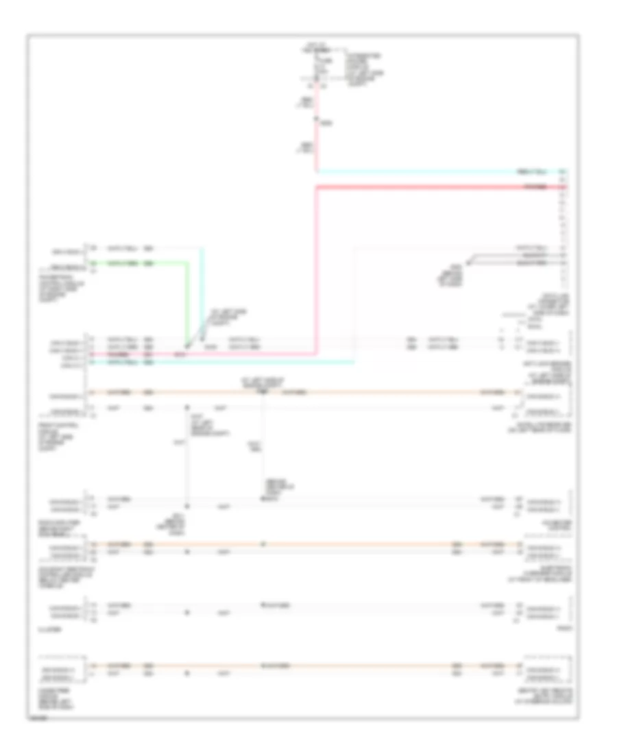
Manual A/C Wiring Diagram for Mitsubishi Raider SE 2007
 https://portal-diagnostov.com/license.html
Automotive Electricians Portal FZCO
Automotive Electricians Portal FZCO
https://portal-diagnostov.com/license.html
https://portal-diagnostov.com/license.html
Automotive Electricians Portal FZCO
Automotive Electricians Portal FZCO
List of elements for Manual A/C Wiring Diagram for Mitsubishi Raider SE 2007:
- (at left rear of engine compt) s107
- (at left side of engine compt) s105
- (on right front of engine) a/c compressor clutch
- 87a
- A/c clutch relay
- A/c clutch rly ctrl
- A/c pressure transducer (at right front of engine compt)
- A/c-heater control
- Blend door actuator (on right side of hvac unit)
- Blend door drv
- Blower motor (on front of hvac unit)
- Blower motor high speed
- Blower motor low speed
- Blower motor m1 speed
- Blower motor m2 speed
- Blower motor relay
- Blower motor resistor (on right side of hvac unit)
- C121
- C13
- C18
- C21
- C29
- C32
- C34
- C61
- C71
- C72
- C73
- C75
- C801
- Can (+)
- Can (-)
- Can b bus (+)
- Can b bus (-)
- Center of dash)
- Cluster
- Common door drv
- Computer data lines system
- D54
- D55
- D64
- D65
- Door drv
- E12
- Ect sig
- Engine coolant temperature sensor (on right front side of engine)
- Evap temp sens sig
- Evaporator temp sens sig
- Evaporator temperature sensor (on hvac unit)
- F504
- Fcm sens rtn
- Floor to defrost mode door actuator
- Floor to panel mode door actuator
- Front control module (at left side of engine compt)
- Fuse 11 10a
- Fuse 35 40a
- Fuse 59 10a
- Fuse 7 10a
- Fused ign sw out (run)
- G108 (on lower right front of engine)
- G200 (behind left side of dash)
- G201 (behind right side of dash)
- Ground
- Hot at all times
- Hot in run
- Ign sw out (run)
- Integrated power module (at left side of engine compt)
- Ipm
- K900
- Mode door 1 drv
- Mode door 2 drv
- Panel lamps drv
- Powertrain control module (at right side of engine compt)
- Pressure sig
- Recirculation
- Recirculation door actuator (on right side of hvac unit)
- Recirculation door drv
- S114 (at right side of engine compt)
- S115 (at right side of engine compt)
- S123 (3.7l: right rear of engine) (4.7l: at top right of engine)
- S211 (behind center of dash)
- S217
- Sens gnd
- T103
- Transmissions system
- Z24
- Z961
ANTI-LOCK BRAKES
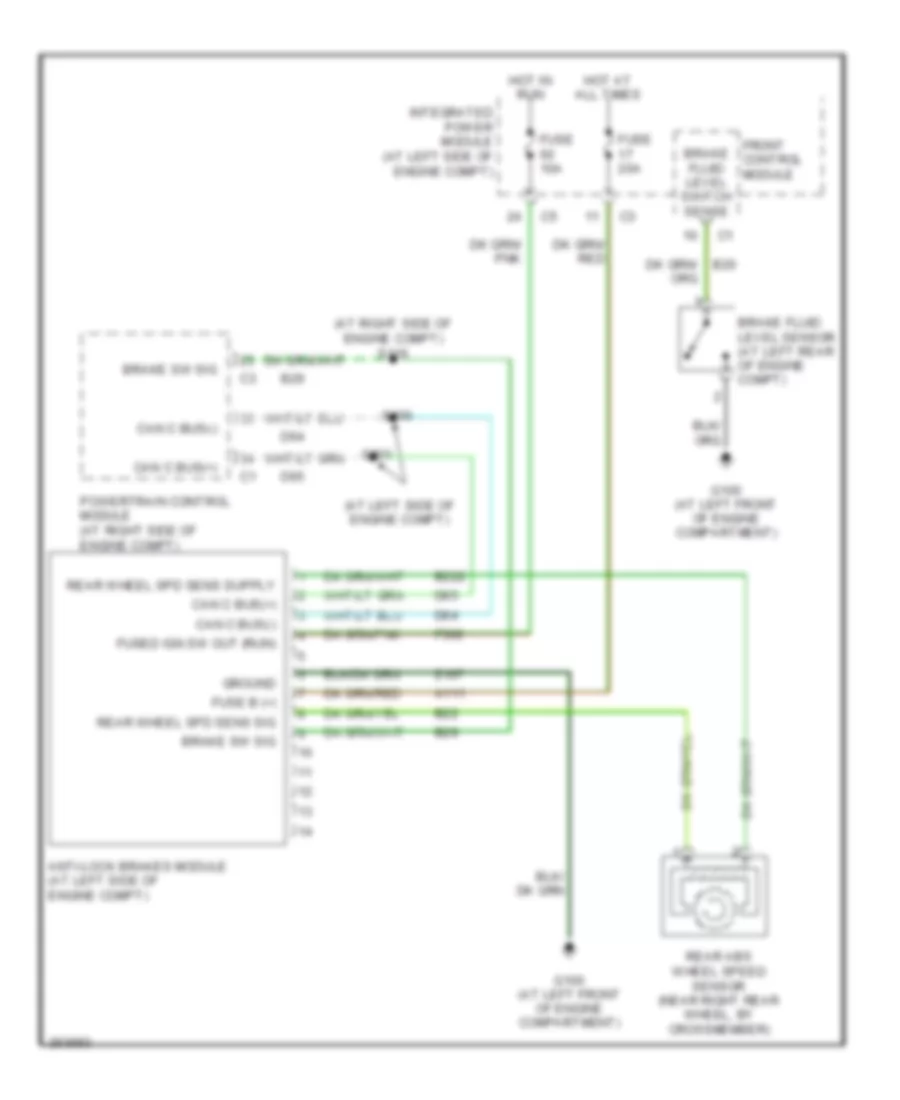
All-Wheel ABS Wiring Diagram for Mitsubishi Raider SE 2007
List of elements for All-Wheel ABS Wiring Diagram for Mitsubishi Raider SE 2007:
- (at left front of engine compartment) g100
- (at left side of engine compt)
- (at left side of engine compt) s101
- A107
- A111
- Anti-lock brakes module (at left side of engine compartment)
- B22
- B222
- B29
- Brake fluid level sensor (at left rear of engine compt)
- Brake fluid level switch sense
- Brake sw sig
- Can c bus(+)
- Can c bus(-)
- D64
- D65
- F500
- Front control module
- Fuse 10a
- Fuse 20a
- Fuse 40a
- Fuse b (+)
- Fused ign sw output (run)
- G100 (at left front of engine compartment)
- Ground
- Hot at all times
- Hot in run
- Integrated power module (at left side of engine compt)
- Left front abs wheel speed sensor (at left front wheel)
- Lf wheel spd sens sig
- Powertrain control module (at right side of engine compt)
- Rear abs wheel speed sensor (near right rear wheel, by crossmember)
- Rear wheel spd sens sig
- Rf wheel spd sens sig
- Right front abs wheel speed sensor (at right front wheel)
- S100
- S116 (at right side of engine compt)
- Tan/ red
- Tan/red
- Z107
- Z923
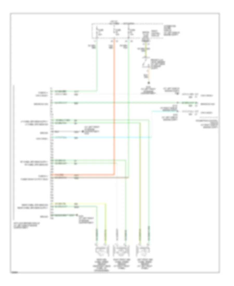
Rear Wheel ABS Wiring Diagram for Mitsubishi Raider SE 2007
List of elements for Rear Wheel ABS Wiring Diagram for Mitsubishi Raider SE 2007:
- (at left side of engine compt)
- (at right side of engine compt) s116
- A111
- Anti-lock brakes module (at left side of engine compt)
- B22
- B222
- B29
- Brake fluid level sensor (at left rear of engine compt)
- Brake fluid level switch sense
- Brake sw sig
- Can c bus(+)
- Can c bus(-)
- D64
- D65
- F500
- Front control module
- Fuse 10a
- Fuse 20a
- Fuse b (+)
- Fused ign sw out (run)
- G100 (at left front of engine compartment)
- Ground
- Hot at all times
- Hot in run
- Integrated power module (at left side of engine compt)
- Powertrain control module (at right side of engine compt)
- Rear abs wheel speed sensor (near right rear wheel, by crossmember)
- Rear wheel spd sens sig
- S100
- S101
- Z107
ANTI-THEFT
Anti-theft Wiring Diagram for Mitsubishi Raider SE 2007
List of elements for Anti-theft Wiring Diagram for Mitsubishi Raider SE 2007:
- (at left side of engine compt) front control module
- (at left side of engine compt) s101
- (at left side of engine compt) s105
- (behind center of dash) s212
- 87a
- A918
- Acc
- Can b bus b(+)
- Can b bus b(-)
- Can b bus(+)
- Can b bus(-)
- Can c bus (+)
- Can c bus (-)
- Can c bus(+)
- Can c bus(-)
- Cluster
- Computer data lines system
- D54
- D55
- D64
- D65
- Driver dr ajar sw
- F20
- Fuse 16 20a
- Fuse 20a
- Fused b(+)
- G20
- G200 (behind left side of dash)
- G300 (at center front of body)
- G300 (except highline) (at center front of body)
- G301 (highline) (club cab: behind left kick panel) (quad cab: at left front of body)
- Ground
- Headlights system
- Hi beam driver
- Horn relay
- Horns system
- Hot at all times
- Ign sw sens in
- Ign sw sense
- Ignition switch
- Integrated power module (at left side of engine compt)
- Ipm
- L33
- L34
- Left front door latch (in left front door)
- Left rear door latch (in left rear door)
- Left rear sw sens
- Lock
- Off
- Pass sw sens
- Powertrain control module (at right side of engine compt)
- Red
- Right front door latch (in right front door)
- Right rear door latch (in right rear door)
- Right rear sw sens
- Rly ctrl
- Run
- S100 (at left side of engine compt)
- S107 (at left rear of engine compt)
- S204
- S206 (except base)
- S211 (behind center of dash)
- S319 (except highline)
- S321 (highline)
- S324 (highline)
- Sens input
- Sentry key remote entry module (at steering column)
- Start
- Z109
BODY CONTROL MODULES
Body Control Modules Wiring Diagram for Mitsubishi Raider SE 2007
List of elements for Body Control Modules Wiring Diagram for Mitsubishi Raider SE 2007:
- (at left front of engine compt) g100
- A/c pressure signal
- Aat sig
- Acc
- Air conditioning system
- Ambient air temperature sensor (at left front of engine compt)
- Asd rly output
- B20
- Back-up lamp feed
- Brake fluid level sw sense
- Brake lamp sw output
- C18
- Can b bus (+)
- Can b bus (-)
- Can c bus (+)
- Can c bus (-)
- Can c diagnostic (+)
- Can c diagnostic (-)
- Computer data lines system
- D201
- D51
- D52
- D54
- D55
- D64
- D65
- Defogger rly ctrl
- Defogger system
- Driver left high beam
- Driver left low beam
- Driver right high beam
- Driver right low beam
- Engine controls system
- Exterior lights system
- F washer pump motor ctrl
- F202
- F924
- Fcm sensor return
- Fog lamp rly ctrl
- Front control module
- Fuse 20a
- Fuse 25a
- Fuse 30a
- Fused b(+)
- G100 (at left front of engine compt)
- G103 (at right front of engine compt)
- G180
- G31
- G70
- G931
- Ground
- Headlights system
- High/low wiper rly ctrl
- Hood ajar sw sns
- Hood ajar switch (left side of engine compt)
- Horn rly ctrl
- Horns system
- Hot at all times
- Ign sw sense input
- Ignition sw out (run)
- Ignition sw out (run-acc)
- Ignition sw out (run-start)
- Ignition switch
- Instrument cluster system
- Integrated power module (at left side of engine compt)
- Ipm
- L trailer tow rly
- L33
- L34
- L43
- L44
- L50
- L60
- L61
- L62
- L63
- Lf turn sig ctrl
- Lock
- Low/rev sol ctrl
- Lr turn sig ctrl
- Mirrors system
- Mode sens a
- Not used
- Off
- On/off wiper rly ctrl
- Park lamp rly ctrl
- Pnk/red
- Power distribution system
- R trailer tow rly
- Rf turn sig ctrl
- Rr turn sig ctrl
- Run
- S204
- Sensor ground
- Shift motor ctrl a
- Shift motor ctrl b
- Start
- Starting/charging system
- T103
- T313
- T315
- T316
- Transfer case mtr lock sig
- Transmissions system
- W10
- Washer fluid level sw sns
- Wiper park sw sns
- Wiper/washer system
- Z116
- Z117
- Z118
- Z909
- Z921
- Z947
- Z965
COMPUTER DATA LINES
Computer Data Lines Wiring Diagram for Mitsubishi Raider SE 2007
List of elements for Computer Data Lines Wiring Diagram for Mitsubishi Raider SE 2007:
- (at left side of engine compt)
- (at left side of engine compt) s105
- (behind center of dash) s212
- A/c-heater control
- Anti-lock brakes module (at left side of engine compt)
- Awal
- Can b bus (+)
- Can b bus (-)
- Can c (+)
- Can c (-)
- Can c bus (+)
- Can c bus (-)
- Cluster
- D51
- D52
- D54
- D55
- D64
- D65
- Data link connector (at lower left side of dash)
- Electronic overhead module (at front of headliner)
- Front control module (at left side of engine compt)
- Fuse 20a
- G200 (behind left side of dash)
- Hands free module (behind left side of dash)
- Hot at all times
- Integrated power module (at left side of engine compt)
- Occupant restraint controller module (below center console)
- Pnk/red
- Powertrain control module (at right side of engine compt)
- Radio
- Radio amplifier (behind right kick panel)
- Rwal
- S100
- S101
- S107 (at left rear of engine compt)
- S206
- S211 (behind center of dash)
- Satellite receiver (on left rear of floor)
- Sentry key remote entry module (at steering column)
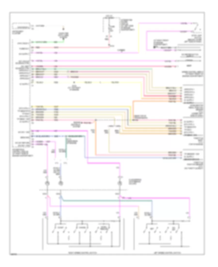
CRUISE CONTROL
Cruise Control Wiring Diagram for Mitsubishi Raider SE 2007
List of elements for Cruise Control Wiring Diagram for Mitsubishi Raider SE 2007:
- (at right front of engine compartment) g103
- (near top of transmission) s122
- 3.7l
- 4.7l
- 5 speed
- A919
- Accel/ resume
- Accelerator pedal position sensor (3.7l) (under left side of dash)
- Apps rtn 1
- Apps rtn 2
- Apps sig 1
- Apps sig 2
- Can b bus (+)
- Can c bus (+)
- Cancel
- Clockspring (in steering column)
- Coast
- Computer data lines system
- D65
- Engine controls system
- Etc mtr (+)
- Etc mtr (-)
- F855
- F856
- Fuse 20a
- Fused b (+)
- Hot at all times
- Instrument cluster
- Integrated power module (at left side of engine compartment)
- K122
- K22
- K23
- K400
- K447
- K448
- K900
- K922
- K961
- Left speed control switch
- Nca
- On/ off
- Pnk/red
- Powertrain control module (at right side of engine compartment)
- Red
- Right speed control switch
- S/c brake switch output
- S/c sw 1 sig
- S/c sw return
- S/c vacuum solenoid ctrl
- S/c vent solenoid ctrl apps rtn 1
- S118 (near rear of engine)
- S124 (at top right of engine)
- S133
- Sens gnd
- Sensor ground
- Set
- Speed control servo (at right front of engine compartment)
- Stop lamp switch (behind lower left side of dash)
- Throttle body (3.7l) (top of engine)
- Throttle position sensor (4.7l) (on throttle body)
- Tp sens 1 sig
- Tp sens rtn
- Tp sensor 1 sig
- Tp sig 2
- V32
- V35
- V36
- V37
- V38
- V937
- Vacuum
- Vent
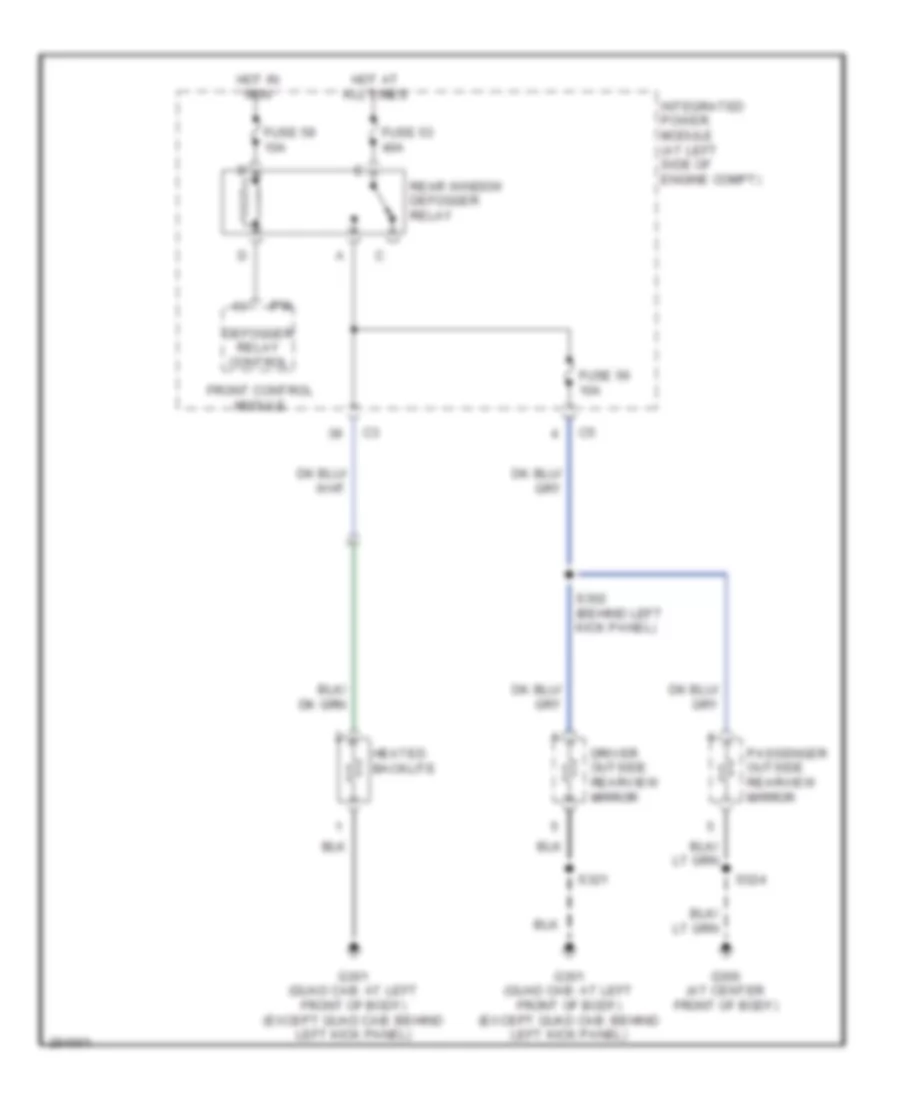
DEFOGGERS
Defoggers Wiring Diagram for Mitsubishi Raider SE 2007
List of elements for Defoggers Wiring Diagram for Mitsubishi Raider SE 2007:
- Defogger relay control
- Driver outside rearview mirror
- Front control module
- Fuse 53 40a
- Fuse 56 10a
- Fuse 59 10a
- G300 (at center front of body)
- G301 (quad cab: at left front of body) (except quad cab: behind left kick panel)
- Heated backlite
- Hot at all times
- Hot in run
- Integrated power module (at left side of engine compt)
- Ipm
- Passenger outside rearview mirror
- Rear window defogger relay
- S302 (behind left kick panel)
- S321
- S324
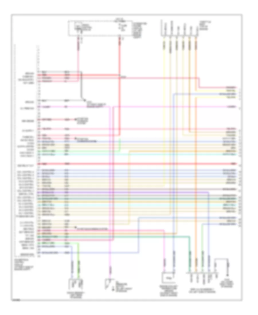
ENGINE PERFORMANCE
3.7L
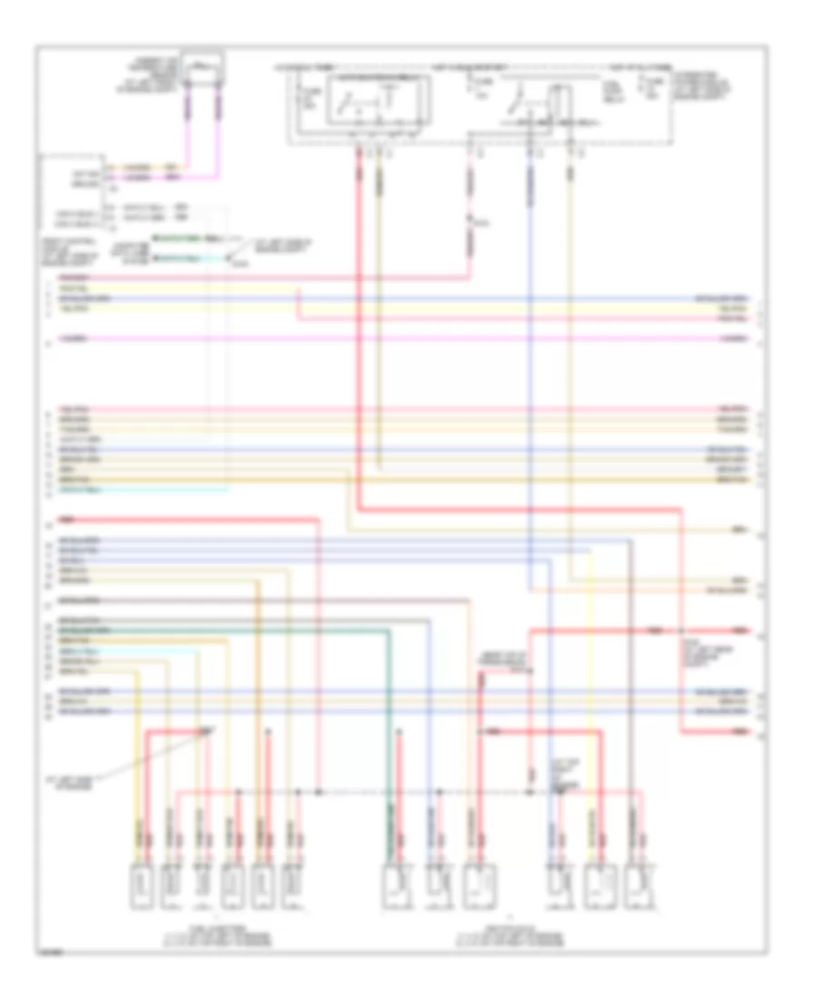
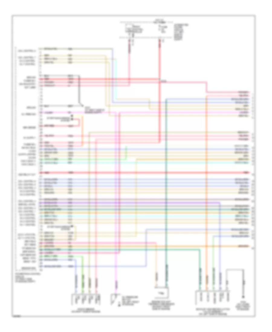
3.7L, Engine Performance Wiring Diagram (1 of 5) for Mitsubishi Raider SE 2007
List of elements for 3.7L, Engine Performance Wiring Diagram (1 of 5) for Mitsubishi Raider SE 2007:
- 1/1 htr ctrl
- 1/2 sig
- 2/1 htr ctrl
- 2/2 sig
- 5v sply
- A803
- A919
- A955
- Asd relay out
- Can c bus (+)
- Can c bus (-)
- Coil control 1
- Coil control 2
- Coil control 3
- Coil control 4
- Coil control 5
- Coil control 6
- Ctrl
- D64
- D65
- Ect sens sig
- Egr sig
- Egr sol
- Egr sol ctrl
- Egr valve assembly (on left side of engine)
- Engine coolant temperature sensor (on right front side of engine)
- Etc motor(+)
- Etc mtr (+)
- Etc mtr (-)
- F202
- F856
- F924
- Front control module ipm
- Fuse 20a
- Fused b(+)
- G107 (at right side of engine compt)
- G108 (on lower right front of engine)
- Gen field
- Gen sense
- Gnd
- Ground
- Hot at all times
- Ign (run-strt)
- Ign sw (run)
- Inj 1 control
- Inj 2 control
- Inj 3 control
- Inj 4 control
- Inj 5 control
- Inj 6 control
- Integrated power module (at left side of engine compt)
- K10
- K11
- K12
- K13
- K14
- K141
- K15
- K16
- K17
- K18
- K19
- K199
- K20
- K22
- K243
- K34
- K35
- K38
- K42
- K447
- K58
- K900
- K902
- K922
- K942
- K99
- Knock sensor 1 (left rear of engine)
- Map sens sig
- Not used
- O2 rtn upstrm
- Oil pres sig
- Oil pressure switch (on left front of engine)
- Powertrain control module (at right side of engine compt)
- Red
- Rtn
- S133
- Sens 1
- Sens 1 rtn
- Sens 1 sig
- Sens gnd
- Sensor gnd
- Starting/ charging system
- Starting/charging system
- Throttle body (top of engine)
- Tp 1 sig
- Tp 2 sig
- Tp sens return
- Tp sens rtn
- Z913
- Z937
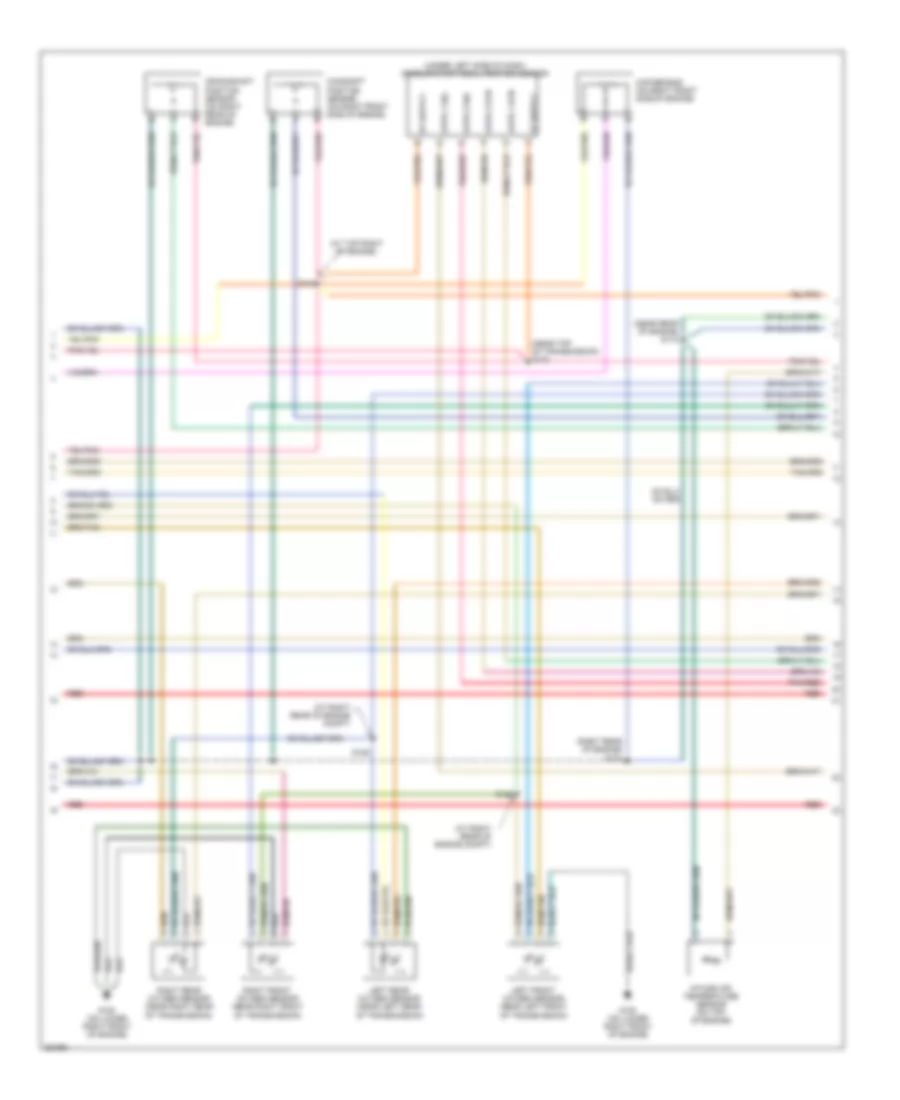
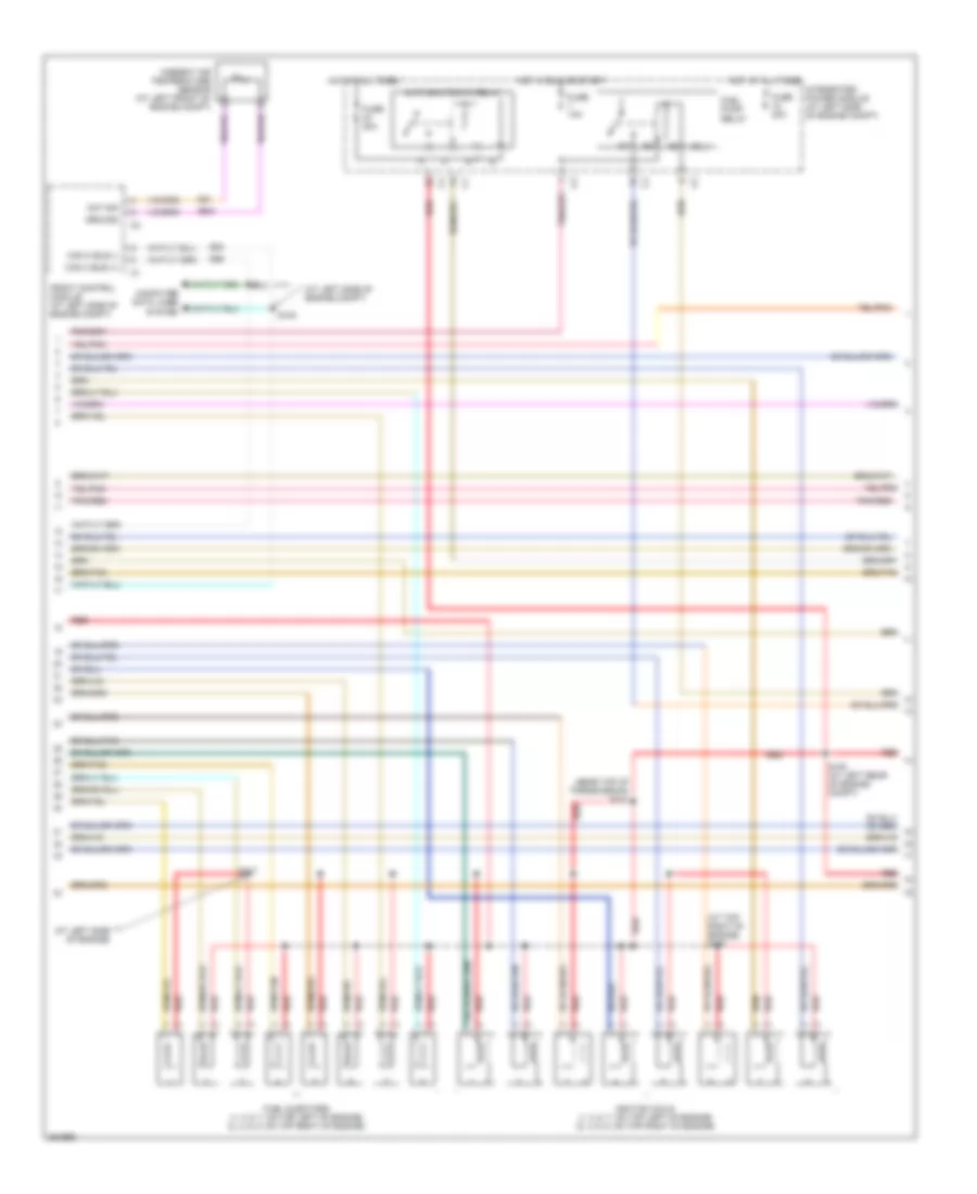
3.7L, Engine Performance Wiring Diagram (2 of 5) for Mitsubishi Raider SE 2007
List of elements for 3.7L, Engine Performance Wiring Diagram (2 of 5) for Mitsubishi Raider SE 2007:
- (at left side of engine compt)
- (at left side of engine)
- (at top right of engine) s127
- (near top of transmission) s121
- Aat sig
- Ambient air temperature sensor (at left front of engine compt)
- Auto shutdown relay
- Can c bus (+)
- Can c bus (-)
- Computer data lines system
- D64
- D65
- Front control module (at left side of engine compt)
- Fuel injectors (1, 3, 5: on top left of engine) (2, 4, 6: on top right of engine)
- Fuel pump relay
- Fuse 10a
- Fuse 20a
- Fuse 30a
- G31
- G931
- Ground
- Hot at all times
- Hot in run or start
- Ignition coils (1, 3, 5: on top left of engine) (2, 4, 6: on top right of engine)
- Integrated power module (at left side of engine compt)
- Red
- S100
- S101
- S104
- S108 (at left rear of engine compt)
- S117
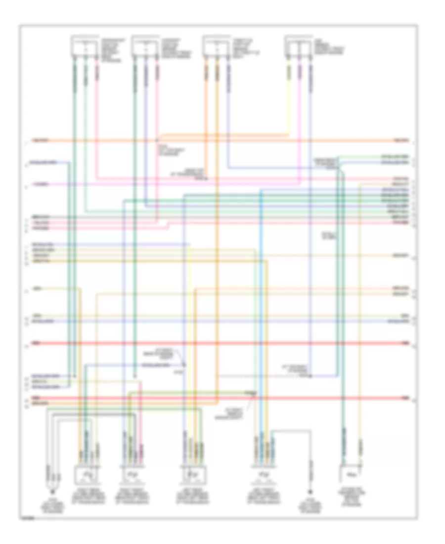
3.7L, Engine Performance Wiring Diagram (3 of 5) for Mitsubishi Raider SE 2007
List of elements for 3.7L, Engine Performance Wiring Diagram (3 of 5) for Mitsubishi Raider SE 2007:
- (at right rear of engine compt)
- (at top right of engine)
- (near rear of engine) s118
- (near top of transmission) s122
- (right rear of engine) s123
- (under left side of dash) accelerator pedal position sensor
- Apps 1 rtn
- Apps 1 sig
- Apps 2 rtn
- Apps 2 sig
- Camshaft position sensor (on right front side of engine)
- Crankshaft position sensor (on right rear of engine)
- G108 (on lower right front of engine)
- Intake air temperature sensor (on top of engine)
- Left front oxygen sensor (near left front of transmission)
- Left rear oxygen sensor (near left rear of transmission)
- Map sensor (on right front side of engine)
- Pnk/red
- Red
- Right front oxygen sensor (near right front of transmission)
- Right rear oxygen sensor (near right rear of transmission)
- S124
- S125
- S126
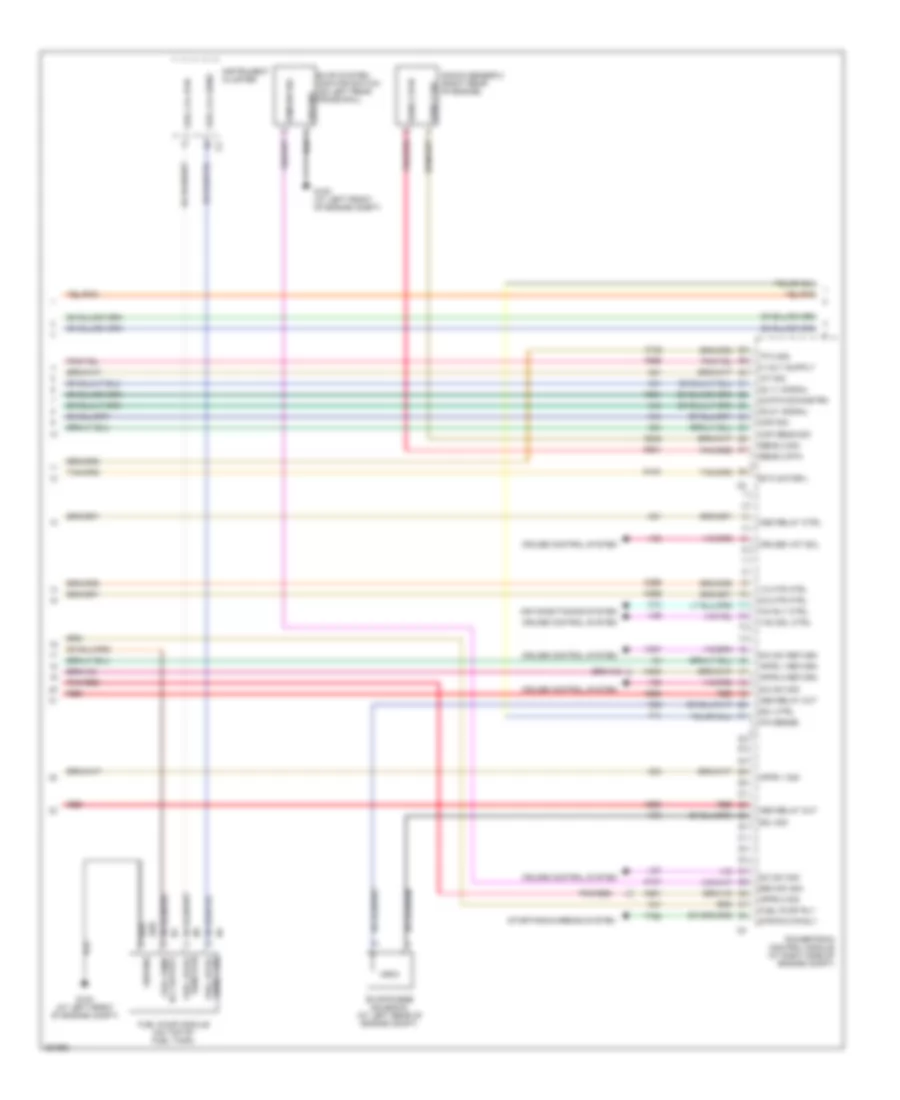
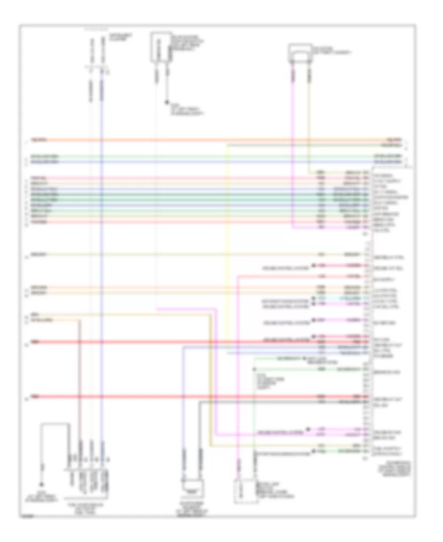
3.7L, Engine Performance Wiring Diagram (4 of 5) for Mitsubishi Raider SE 2007
List of elements for 3.7L, Engine Performance Wiring Diagram (4 of 5) for Mitsubishi Raider SE 2007:
- 02 rtn downstrm
- 1/2 htr ctrl
- 2/2 htr ctrl
- A/c rly ctrl
- A955
- Air conditioning system
- Apps 1 return
- Apps 1 sig
- Apps 2 return
- Apps 2 sig
- Asd relay ctrl
- Asd relay out
- C13
- Ckp sens sig
- Cmp sig
- Cruise control system
- Cruise vnt sol
- Esm sw sig
- Etc motor(-)
- Evap system monitor switch (on left rear frame rail)
- Evap/purge solenoid (at left rear of engine compt)
- F855
- Fuel level
- Fuel lvl rtn
- Fuel lvl sens
- Fuel pump module (on top of fuel tank)
- Fuel pump rly
- Fuel pump rly output
- G100 (at left front of engine compt)
- Ground
- Iat sig
- Instrument cluster
- K107
- K122
- K21
- K23
- K24
- K242
- K299
- K31
- K399
- K400
- K41
- K43
- K44
- K448
- K51
- K52
- K70
- K904
- K924
- K961
- Knock sensor 2 (right rear of engine)
- O2 1/1 signal
- O2 2/1 signal
- P/n sense
- Pnk/red
- Powertrain control module (at right side of engine compt)
- Red
- S/c sw return
- S/c sw sig
- Sens 1 sig
- Sens 2 rtn
- Sens 2 sig
- Sens rtn
- Sol ctrl
- Sol sig
- Starting/charging system
- Strtr mtr rly
- T41
- T752
- Tp 2 sig
- V35
- V36
- V37
- V38
- V937
- Vac sol ctrl
- Z201
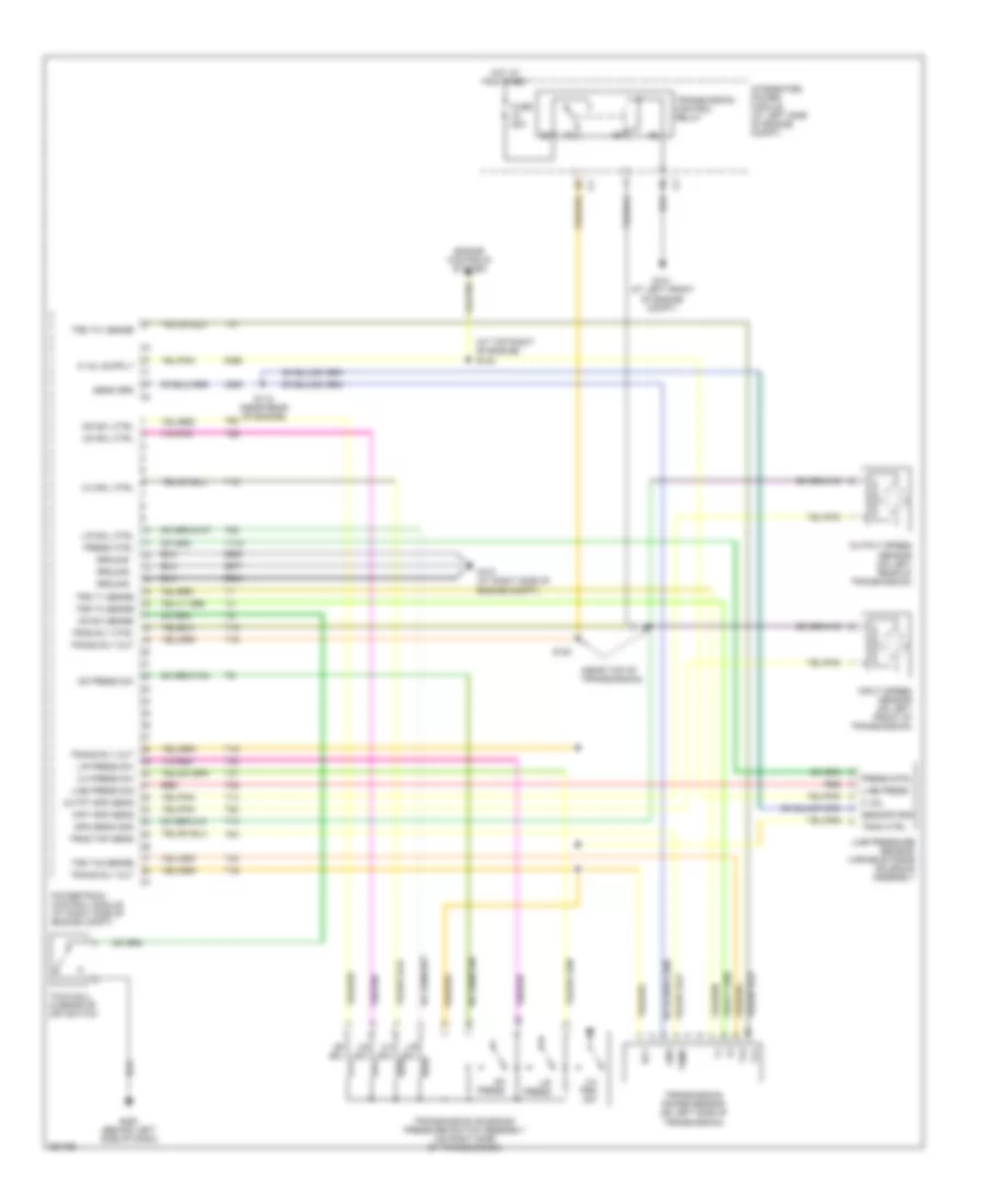
3.7L, Engine Performance Wiring Diagram (5 of 5) for Mitsubishi Raider SE 2007
List of elements for 3.7L, Engine Performance Wiring Diagram (5 of 5) for Mitsubishi Raider SE 2007:
- (near top of transmission)
- 2-4 press sw
- 2-4 prs sw
- 2-4 sol
- 2-4 sol ctrl
- A/t
- Clutch interlock switch (at lower left side of dash)
- Fuse 25a
- G101 (at left front of engine compt)
- G107 (at right side of engine compt)
- G200 (behind left side of dash)
- Gnd
- Ground
- Hot at all times
- Inpt spd sens
- Input speed sensor (m/t) (on left front of transmission)
- Integrated power module (at left side of engine compt)
- L/r press
- L/r press sw
- L/r sol
- L/r sol ctrl
- Line press sig
- Line pressure sensor/ variable force solenoid assembly
- M/t
- Od press
- Od press sw
- Od sol
- Od sol ctrl
- Od sw sense
- Outpt spd sens
- Output speed sensor (m/t) (on left rear of transmission)
- Powertrain control module (at right side of engine compt)
- Press ctrl
- Rly
- S119
- S120
- Sens ctrl
- Sens gnd
- Sens sig
- Sol ctrl
- T118
- T13
- T14
- T15
- T16
- T19
- T20
- T38
- T41
- T42
- T47
- T50
- T52
- T54
- T59
- T60
- Temp
- Tow/haul overdrive off switch
- Tran ctrl
- Trans rly out
- Trans rly out c4
- Transmission control relay
- Transmission range sensor (on left side of transmission)
- Transmission solenoid/ pressure switch assembly (on right side of transmission)
- Trns rly ctrl
- Trns tmp sens
- Trs t1 sense
- Trs t3 sense
- Trs t42 sense
- Ud sol
- Ud sol ctrl
- Z904
- Z908
- Z977
4.7L
4.7L, Engine Performance Wiring Diagram (1 of 5) for Mitsubishi Raider SE 2007
List of elements for 4.7L, Engine Performance Wiring Diagram (1 of 5) for Mitsubishi Raider SE 2007:
- 1/2 sig
- 2/2 sig
- 5v sply
- A803
- A919
- A955
- Asd relay out
- Can c bus (+)
- Can c bus (-)
- Coil control 1
- Coil control 2
- Coil control 3
- Coil control 4
- Coil control 5
- Coil control 6
- Coil control 7
- Coil control 8
- Ctrl egr sol
- D64
- D65
- Ect sens
- Egr sig
- Egr signal
- Egr sol cntrl
- Engine coolant temperature sensor (on right front side of engine)
- Exhaust gas recirculation valve assembly (on left side of engine)
- F202
- F856
- F924
- Front control module
- Fuse 20a
- Fused b(+)
- G107 (at right side of engine compt)
- G108 (on lower right front of engine)
- Gen field
- Gen sense
- Ground
- Hot at all times
- Ign (run-strt)
- Ign sw (run)
- Inj 1 control
- Inj 2 control
- Inj 3 control
- Inj 4 control
- Inj 5 control
- Inj 6 control
- Inj 7 control
- Inj 8 control
- Integrated power module (at left side of engine compt)
- Ipm
- K10
- K11
- K12
- K13
- K14
- K141
- K15
- K16
- K17
- K18
- K19
- K199
- K20
- K22
- K243
- K26
- K28
- K34
- K35
- K38
- K42
- K58
- K900
- K902
- K942
- K97
- K98
- K99
- Knock sensor (on right side of engine)
- Map sens sig
- Not used
- O2 1/1 htr ctrl
- O2 2/1 htr ctrl
- O2 rtn upstrm
- Oil pres sig
- Oil pressure switch (on left front of engine)
- Pnk/red
- Powertrain control module (at right side of engine compt)
- Red
- S133
- Sens 1 rtn
- Sens 1 sig
- Sens 2 rtn
- Sens 2 sig
- Sens gnd
- Sensor gnd
- Starting/charging system
- Tp sens sig
- Z913
- Z937
4.7L, Engine Performance Wiring Diagram (2 of 5) for Mitsubishi Raider SE 2007
List of elements for 4.7L, Engine Performance Wiring Diagram (2 of 5) for Mitsubishi Raider SE 2007:
- (at left side of engine compt)
- (at left side of engine)
- (at top right of engine) s127
- (near top of transmission) s121
- Aat sig
- Ambient air temperature sensor (at left front of engine compt)
- Auto shutdown relay
- Can c bus (+)
- Can c bus (-)
- Computer data lines system
- D64
- D65
- Front control module (at left side of engine compt)
- Fuel injectors (1, 3, 5, 7: on top left of engine) (2, 4, 6, 8: on top right of engine)
- Fuel pump relay
- Fuse 10a
- Fuse 20a
- Fuse 30a
- G31
- G931
- Ground
- Hot at all times
- Hot in run or start
- Ignition coils (1, 3, 5, 7: on top left of engine) (2, 4, 6, 8: on top right of engine)
- Integrated power module (at left side of engine compt)
- Pnk/red
- Red
- S100
- S101
- S108 (at left rear of engine compt)
- S117
4.7L, Engine Performance Wiring Diagram (3 of 5) for Mitsubishi Raider SE 2007
List of elements for 4.7L, Engine Performance Wiring Diagram (3 of 5) for Mitsubishi Raider SE 2007:
- (at right rear of engine compt)
- (at top right of engine) s123
- (near rear of engine) s118
- (near top of transmission) s122
- Camshaft position sensor (on right front side of engine)
- Crankshaft position sensor (on right rear of engine)
- G108 (on lower right front of engine)
- Intake air temperature sensor (on top of engine)
- Left front oxygen sensor (near left front of transmission)
- Left rear oxygen sensor (near left rear of transmission)
- Map sensor (on right front side of engine)
- Pnk/red
- Red
- Right front oxygen sensor (near right front of transmission)
- Right rear oxygen sensor (near right rear of transmission)
- S124 (at top right of engine)
- S125
- S126
- Throttle position sensor (on throttle body)
4.7L, Engine Performance Wiring Diagram (4 of 5) for Mitsubishi Raider SE 2007
List of elements for 4.7L, Engine Performance Wiring Diagram (4 of 5) for Mitsubishi Raider SE 2007:
- 1/2 htr ctrl
- 2/2 htr ctrl
- A/c rly ctrl
- A955
- Air conditioning system
- Anti-lock brakes system
- Asd relay ctrl
- Asd relay out
- B29
- Brake sw sig
- C13
- Ckp sens sig
- Cmp sig
- Cruise control system
- Cruise sw sig
- Cruise vnt sol
- Esm sw sig
- Evap system monitor switch (on left rear frame rail)
- Evap/purge solenoid (at left rear of engine compt)
- F855
- Fuel level sens 1 sig
- Fuel level sens rtn
- Fuel lvl rtn
- Fuel lvl sens
- Fuel pump
- Fuel pump module (on top of fuel tank)
- Fuel pump rly
- G100 (at left front of engine compt)
- Ground
- Iac ctrl
- Iac motor (on throttle body)
- Iac signal
- Iat sig
- Instrument cluster
- K107
- K21
- K24
- K242
- K299
- K31
- K399
- K41
- K43
- K44
- K51
- K52
- K61
- K70
- K904
- K924
- K961
- O2 1/1 signal
- O2 2/1 signal
- O2 rtn downstrm
- P/n sense
- Pnk/red
- Powertrain control module (at right side of engine compt)
- Red
- Rly output
- S/c sply
- S116 (at right side of engine compt)
- Sens 2 rtn
- Sens 2 sig
- Sol ctrl
- Sol sig
- Starting/charging system
- Strtr mtr rly
- Sw 2 sig
- Sw return
- Sw sig stop lamp switch (behind lower left side of dash)
- T41
- T752
- V32
- V35
- V36
- V37
- V38
- V937
- Vac sol ctrl
- Z201
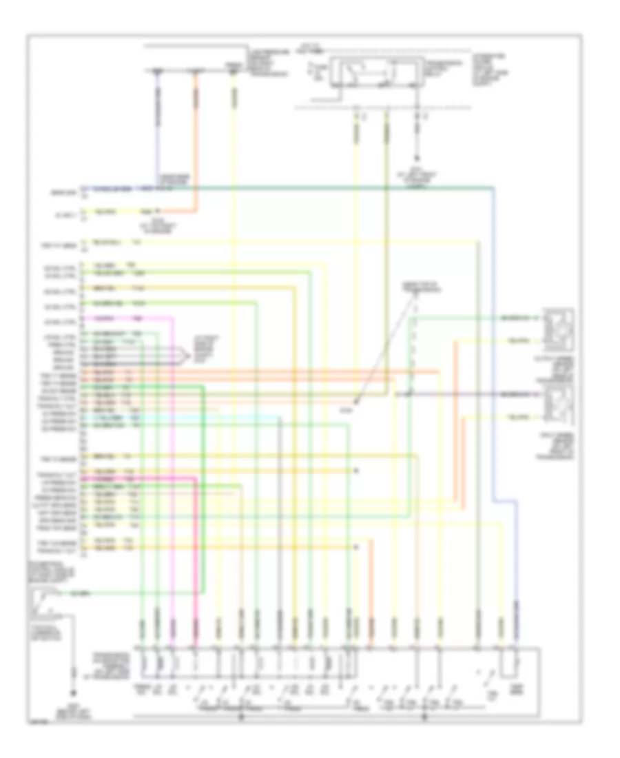
4.7L, Engine Performance Wiring Diagram (5 of 5) for Mitsubishi Raider SE 2007
List of elements for 4.7L, Engine Performance Wiring Diagram (5 of 5) for Mitsubishi Raider SE 2007:
- (at right side of engine compt) g107
- (near top of transmission)
- 2c press
- 2c press sw
- 2c sol
- 2c sol ctrl
- 4c press
- 4c press sw
- 4c sol
- 4c sol ctrl
- 5 volt
- A/t
- Clutch interlock switch (at lower left side of dash)
- Fuse 25a
- G101 (at left front of engine compt)
- G200 (behind left side of dash)
- Gnd
- Ground
- Hot at all times
- Inpt spd sens
- Input speed sensor (a/t) (on left front of transmission)
- Integrated power module (at left side of engine compt)
- L/r press
- L/r press sw
- L/r sol
- L/r sol ctrl
- Line pressure sensor (on right rear of transmission)
- Line prs sens
- M/t
- Ms sol
- Ms sol ctrl
- Od press
- Od press sw
- Od sol
- Od sol ctrl
- Od sw sense
- Outpt spd sens
- Output speed sensor (a/t) (on left rear of transmission)
- Powertrain control module (at right side of engine compt)
- Pres ctrl
- Press sig
- Press sol
- S119
- S120
- Spd sens gnd
- T118
- T13
- T14
- T140
- T147
- T15
- T16
- T20
- T219
- T259
- T29
- T38
- T42
- T48
- T50
- T52
- T54
- T59
- T60
- Temp sens
- Tow/haul overdrive off switch
- Trans rly out
- Trans rly out c4
- Transmission control relay
- Transmission solenoid/trs assembly (on left side of transmission)
- Trns rly ctrl
- Trns tmp sens
- Trs t1
- Trs t1 sense
- Trs t2
- Trs t2 sense
- Trs t3
- Trs t3 sense
- Trs t41
- Trs t42
- Trs t42 sense
- Ud press
- Ud press sw
- Ud sol
- Ud sol ctrl
- Z904
- Z908
- Z977
EXTERIOR LIGHTS
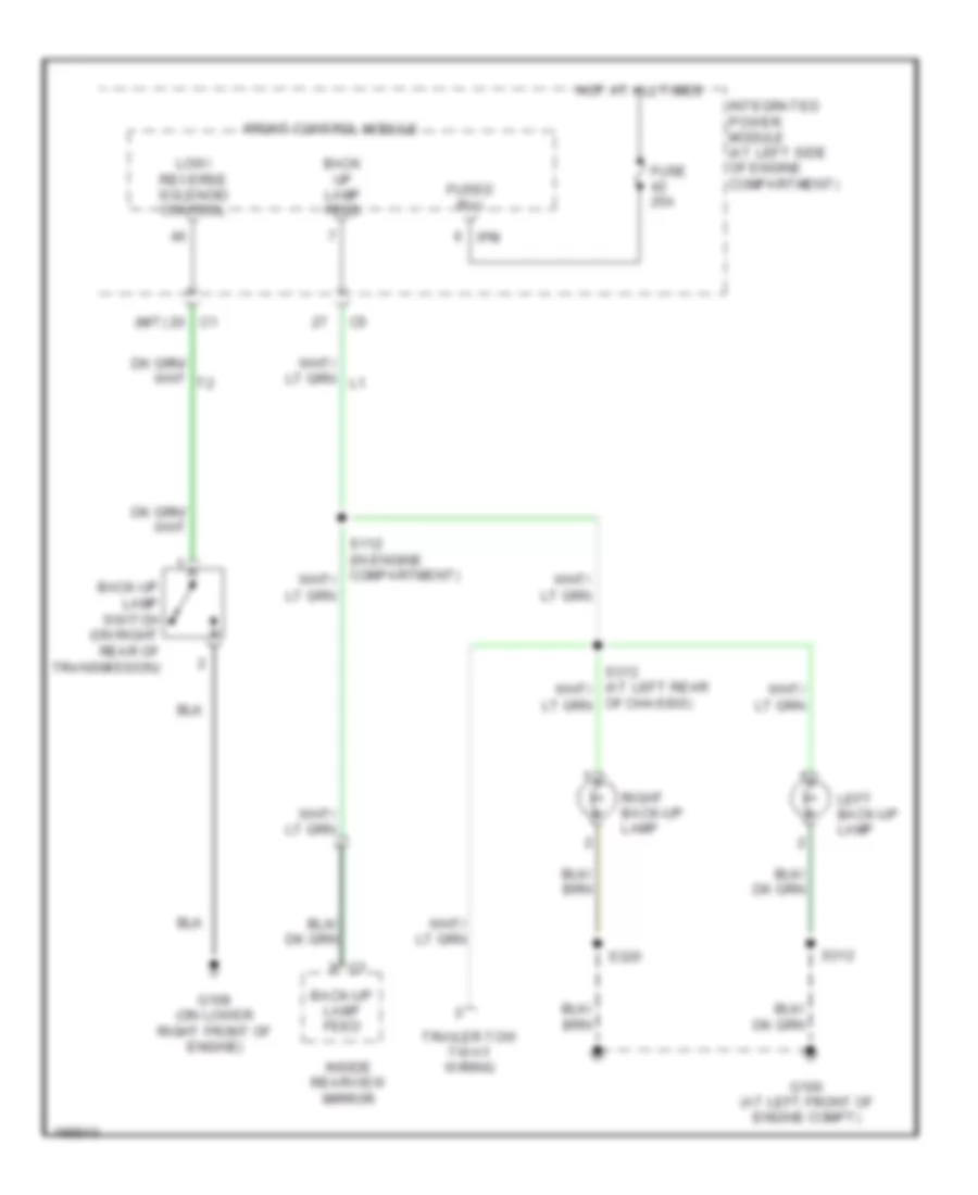
Back-up Lamps Wiring Diagram for Mitsubishi Raider SE 2007
List of elements for Back-up Lamps Wiring Diagram for Mitsubishi Raider SE 2007:
- (m/t)
- Back up lamp feed
- Back-up lamp feed
- Back-up lamp switch (on right rear of transmission)
- Front control module
- Fuse 25a
- Fused b(+)
- G100 (at left front of engine compt)
- G108 (on lower right front of engine)
- Hot at all times
- Inside rearview mirror
- Integrated power module (at left side of engine compartment)
- Ipm
- Left back-up lamp
- Low/ reverse solenoid control
- Of chassis)
- Right back-up lamp
- S312
- S320
- Trailer tow 7-way wiring
Exterior Lamps Wiring Diagram for Mitsubishi Raider SE 2007
List of elements for Exterior Lamps Wiring Diagram for Mitsubishi Raider SE 2007:
- (at left side of engine compt) s100
- (at left side of engine compt) s101
- (at right side of engine compt)
- (at right side of engine compt) s116
- (not used)
- 5 speed
- B29
- Brake lamp sw out
- Brake provision module (at lower left side of dash)
- Brake sw out
- Brake sw signal
- Can c bus (+)
- Can c bus (-)
- Can c bus(+)
- Can c bus(-)
- Cargo lamp drv
- Chmsl aftermarket lamp
- Cluster
- Computer data lines system
- D64
- D65
- Front control module
- Front turn signal ctrl
- Fuse 10a
- Fuse 15a
- Fuse 51 40a
- G100 (at left front of engine compt)
- G101 (at left front of engine compt)
- G103 (at right front of engine compt)
- G200 (behind left side of dash)
- G301 (club cab: behind left kick panel) (quad cab: at left front of body)
- Ground
- Hazard
- Hdlp sw mux
- Hdlp sw mux rtn
- Head
- Headlamp switch
- High mounted stop lamp
- Hot at all times
- Illum sw
- Integrated power module (at left side of engine compartment)
- Ipm
- L50
- Left
- Left front park/ turn lamp
- Left license lamp
- Left rear turn signal ctrl
- Left turn
- Left turn/ tail/ stop lamp
- Multi-function switch (in steering column)
- Off
- Panel lamps
- Park
- Park lamp relay
- Park lamp relay ctrl
- Park lamp relay output
- Pnk/ red
- Powertrain control module
- Rear turn signal ctrl
- Right
- Right front park/ turn lamp
- Right front turn signal ctrl
- Right rear turn signal ctrl
- Right turn
- Right turn/ tail/ stop lamp
- S/c
- S106 (at left rear of engine compt)
- S205 (remote radio) (behind left side of dash)
- S303
- S312
- S314 (at left rear of chassis)
- S320
- Sound systems
- Speed control servo (at right front of engine compartment)
- Stop lamp switch (behind lower left side of dash)
- Sw mux rtn
- Turn sig input mux
- V32
Trailer Tow Wiring Diagram for Mitsubishi Raider SE 2007
List of elements for Trailer Tow Wiring Diagram for Mitsubishi Raider SE 2007:
- (at left rear of chassis) s317
- (in engine compartment) s112
- 87a
- A400
- B400
- Back- up lamp feed
- Back-up lamp feed
- Back-up lamp feed c1
- Brake lamp switch out
- Brake lp sw output
- Brake provision module (at lower left side of dash)
- Front control module
- Fuse 12 15a
- Fuse 13 15a
- Fuse 30a
- Fuse 45 10a
- G101 (at left front of engine compartment)
- G302
- High mounted stop lamp
- Hot at all times
- Inside rearview mirror
- Integrated power module (at left side of engine compartment)
- Ipm
- L50
- Left back-up lamp
- Left trailer tow brake lamp relay control
- Left trailer tow relay
- Of chassis)
- Park lamp relay
- Pnk/ red
- Pnk/red
- Right back-up lamp
- Right trailer tow brake lamp relay control
- Right trailer tow relay
- S106 (at left rear of engine compartment)
- S313 (at left rear of chassis)
- S315 (w/ trailer tow)
- S316 (at left rear of chassis)
- S318 (at left rear
- Stop lamp switch (behind lower left side of dash)
- Tan/ red
- Tan/red
- Trailer tow 4-way wiring
- Trailer tow 7-way wiring
- W/ trailer tow
- Z911
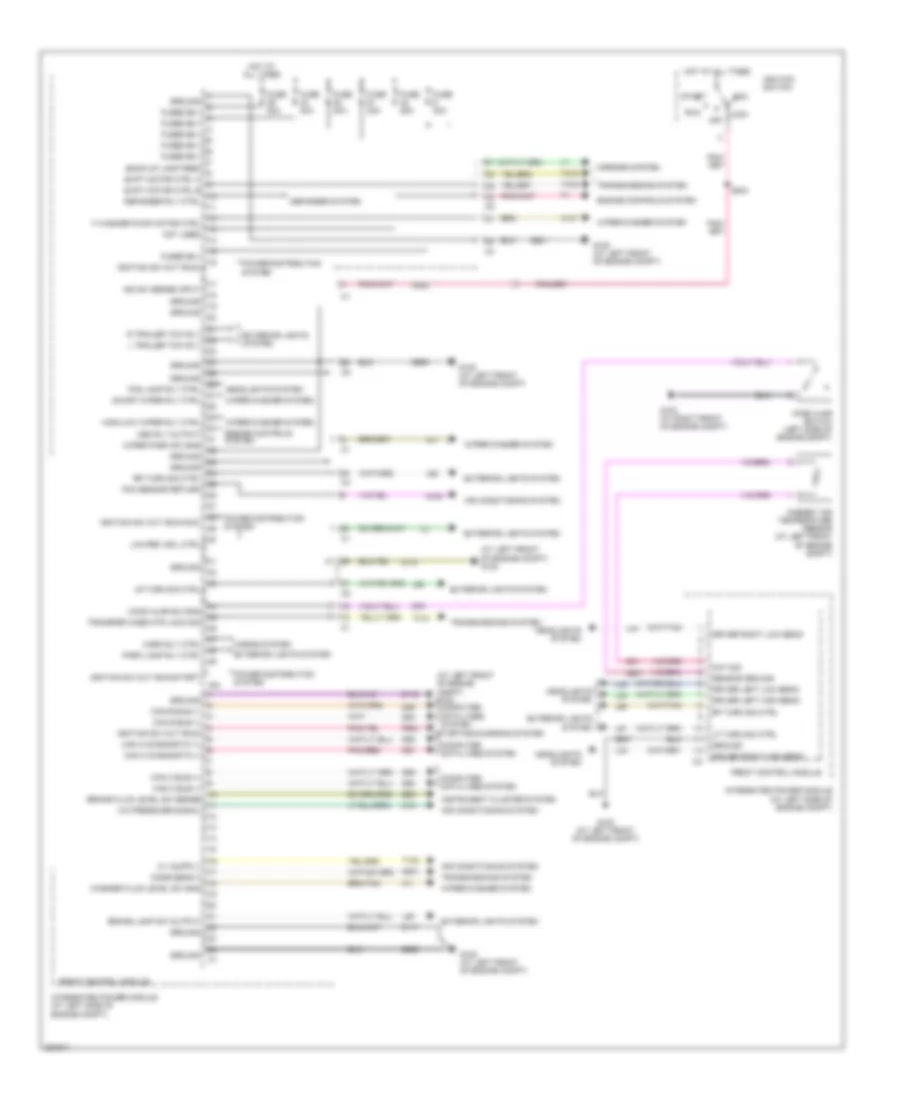
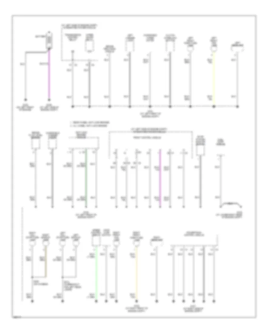
GROUND DISTRIBUTION
Ground Distribution Wiring Diagram (1 of 3) for Mitsubishi Raider SE 2007
List of elements for Ground Distribution Wiring Diagram (1 of 3) for Mitsubishi Raider SE 2007:
- (at left side of engine compt) integrated power module
- 87a
- All wheel anti-lock brakes
- Anti-lock brakes module
- Battery
- Brake fluid level sensor
- Brake provision module
- Clutch
- Evap system monit0r switch
- Front control module
- Fuel pump module
- G100 (at left front of engine compt)
- G101 (at left front of engine compt)
- G102 (at lower right rear of engine compt)
- G103 (at right front of engine compt)
- G105 (on left front of engine)
- G106 (at left side of engine compt)
- G107 (at right side of engine compt)
- Hood ajar switch
- Interlock switch
- Ipm
- Left
- Left backup lamp
- Left front fog lamp
- Left front park/turn lamp
- Left headlamp
- Left tail/ stop/turn lamp
- License lamp
- Powertrain control module
- Rear wheel anti-lock brakes
- Right backup lamp
- Right front fog lamp
- Right front park/turn lamp
- Right headlamp
- Right tail/ stop/turn lamp
- S312 (in breakout for left rear lamps)
- S320 (on chassis)
- Speed control servo
- Transmission control relay
- Windshield
- Windshield washer pump
- Wiper motor
- Wiper on/off relay
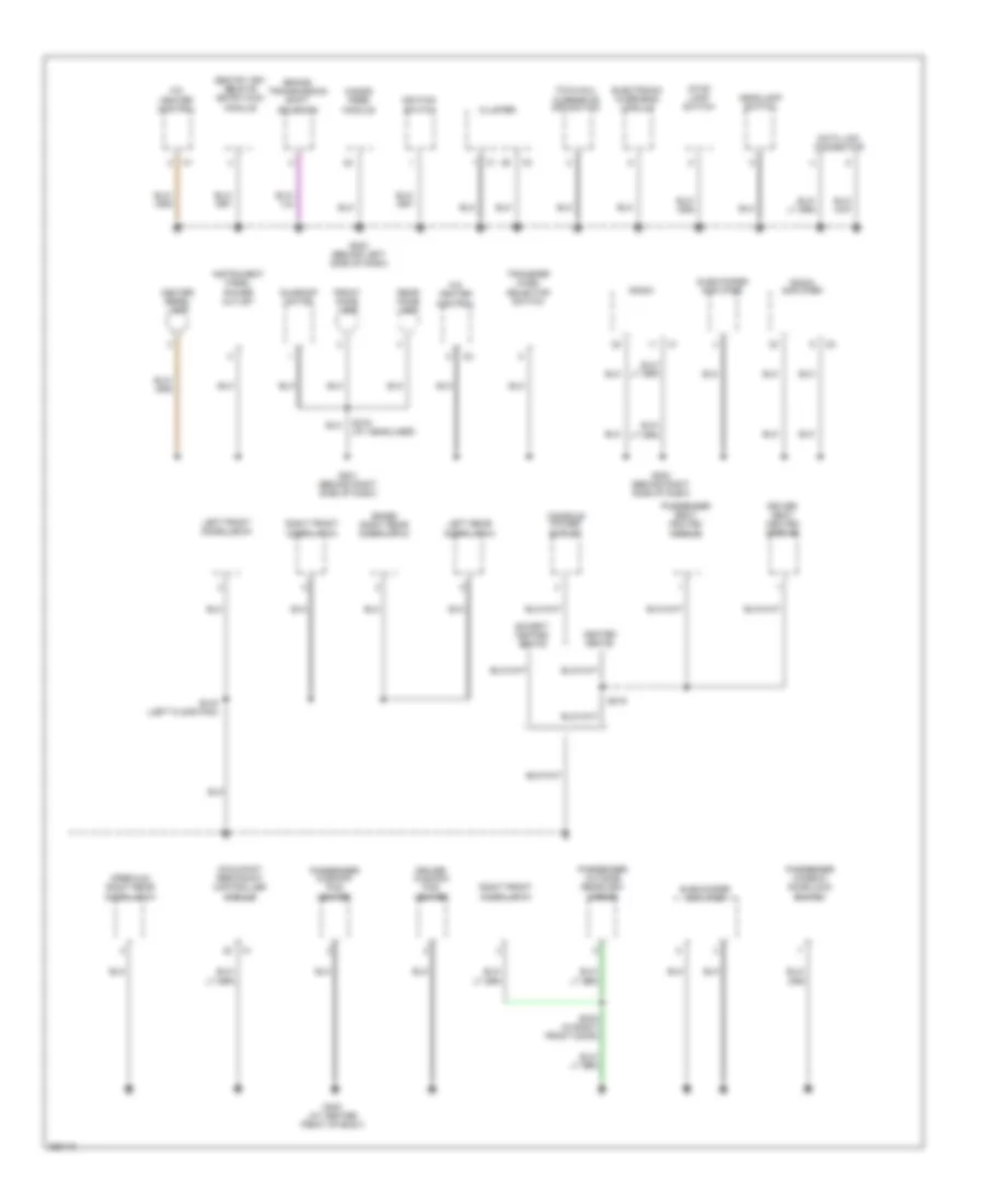
Ground Distribution Wiring Diagram (2 of 3) for Mitsubishi Raider SE 2007
List of elements for Ground Distribution Wiring Diagram (2 of 3) for Mitsubishi Raider SE 2007:
- (base) right rear door latch
- (premium) right rear door latch
- A/c heater control
- Brake transmission shift solenoid
- Center bezel lamp
- Cluster
- Console power outlet
- Data link connector
- Driver cushion pad heater
- Driver seat heated module
- Electronic overhead module
- Except heated seats
- Front dome lamp
- G200 (behind left side of dash)
- G201 (behind right side of dash)
- G202 (behind right side of dash)
- G300 (at center front of body)
- Hands free module
- Headlamp switch
- Heated seats
- Ignition switch
- Instrument panel power outlet
- Left front door latch
- Left rear door latch
- Occupant restraint controller module
- Passenger cushion pad heater
- Passenger outside rearview mirror
- Passenger seat heated module
- Passenger window/ door lock switch
- Radio
- Radio amplifier
- Rear dome lamp
- Right front door latch
- S216 (at headliner)
- S219
- S319 (left floor pan)
- S324 (in right front door)
- Sentry key remote entry/wcm module
- Stop lamp switch
- Subwoofer amplifier
- Sunroof motor
- Tow/haul overdrive off switch
- Transfer case selector switch
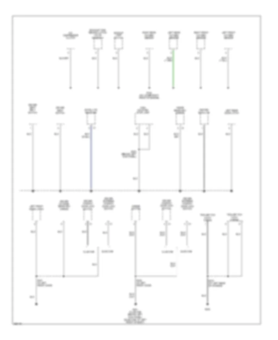
Ground Distribution Wiring Diagram (3 of 3) for Mitsubishi Raider SE 2007
List of elements for Ground Distribution Wiring Diagram (3 of 3) for Mitsubishi Raider SE 2007:
- A/c compressor clutch
- Backup lamp switch
- Club cab
- Driver express window/ door lock switch
- Driver outside rearview mirror
- Driver seat belt switch
- Driver seat switch
- Driver window/ door lock
- Exhaust gas recirculation valve assembly
- G108 (on lower right front of engine)
- G301 (club cab: behind left kick panel) (quad cab: at left front of body)
- G302
- Heated backlite
- High mounted stop lamp
- Inside rearview mirror
- Left front door latch
- Left front oxygen sensor
- Left rear door latch
- Left rear oxygen sensor
- Mirror switch
- Quad cab
- Right front oxygen sensor
- Right rear oxygen sensor
- S303 (behind left kick panel)
- S315 (at left rear of chassis)
- S321 (in left front door)
- S322 (in left front door)
- Satellite receiver
- Switch
- Trailer tow 4-way wiring
- Trailer tow 7-way wiring
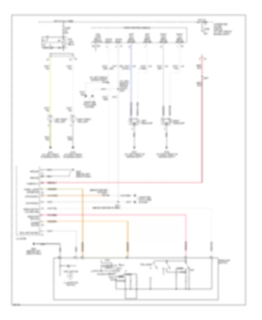
HEADLIGHTS
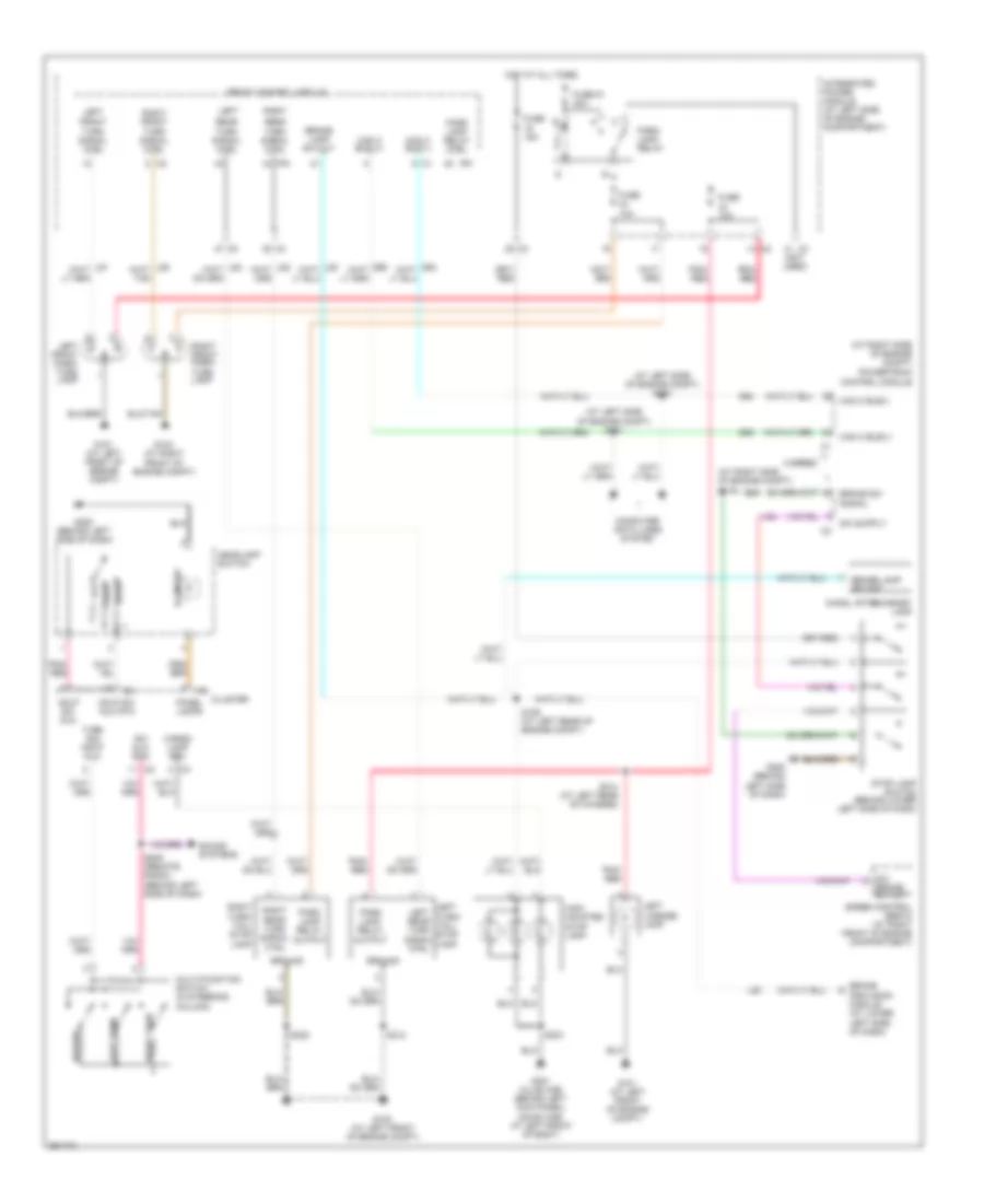
Headlights Wiring Diagram for Mitsubishi Raider SE 2007
List of elements for Headlights Wiring Diagram for Mitsubishi Raider SE 2007:
- (at left rear of engine compt) s107
- (at left side of engine compt) s105
- (behind center of dash)
- 87a
- Can b bus(+)
- Can b bus(-)
- Cargo dome
- Cluster
- Computer data lines system
- D55
- Dim 1
- Dim 2
- Dim 3
- Dim 4
- Dim 5
- Dim 6
- Dimmer sig ind
- Fog lamp ind
- Fog lamp ind drv
- Fog lamp relay
- Fog lamp relay control
- Fog lamps
- Front control module
- Fuse 20a
- Fused b (+)
- G101 (at left front of engine compt)
- G103 (at right front of engine compt)
- G200 (behind left side of dash)
- Ground
- Head
- Headlamp sw mux
- Headlamp sw mux return
- Headlamp switch
- Hot at all times
- Illumination switch
- Integrated power module (at left side of engine compt)
- Ipm
- Left front fog lamp
- Left headlamp
- Left high beam driver
- Left low beam driver
- Off
- Panel lamps dimmer sig c3
- Parade
- Park
- Pnk/red
- Right front fog lamp
- Right headlamp
- Right high beam driver
- Right low beam driver
- S207
- S211 (behind center of dash)
- S212
- Tan
HORN
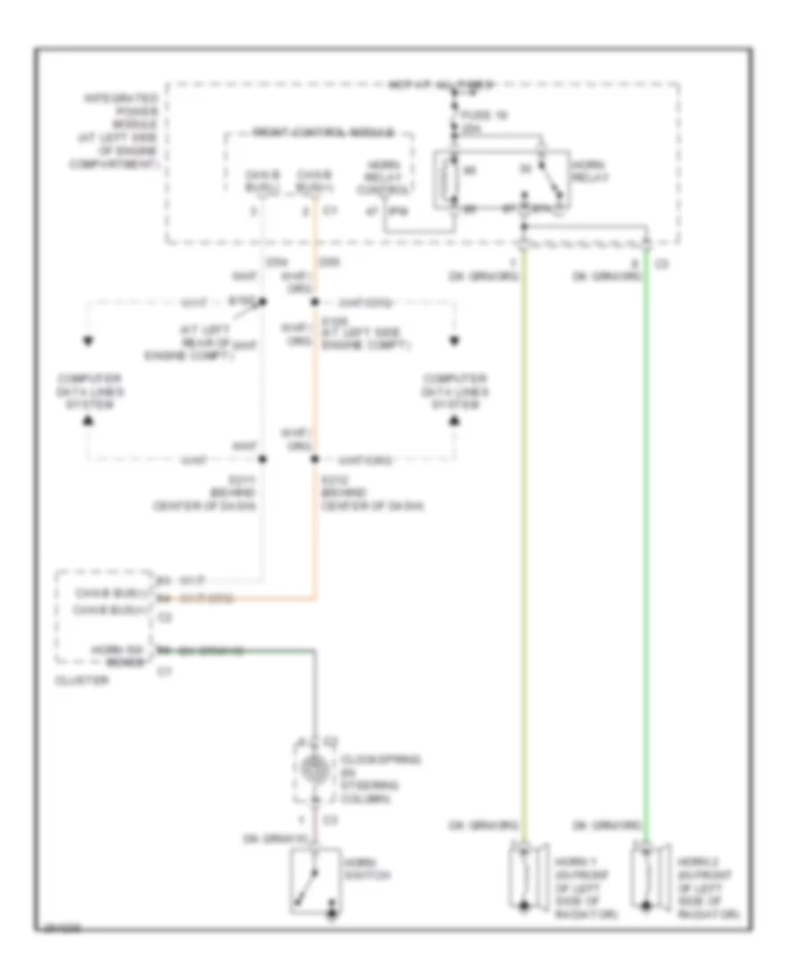
Horn Wiring Diagram for Mitsubishi Raider SE 2007
List of elements for Horn Wiring Diagram for Mitsubishi Raider SE 2007:
- (at left rear of engine compt)
- 87a
- Can b bus(+)
- Can b bus(+) c2
- Can b bus(-)
- Clockspring (in steering column)
- Cluster
- Computer data lines system
- D54
- D55
- Front control module
- Fuse 16 20a
- Horn 1 (in front of left side of radiator)
- Horn 2 (in front of left side of radiator)
- Horn relay
- Horn relay control
- Horn sw
- Horn switch
- Hot at all times
- Integrated power module (at left side of engine compartment)
- Ipm
- S107
- S211 (behind center of dash)
- S212 (behind center of dash)
- Sense
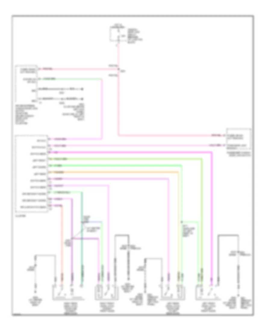
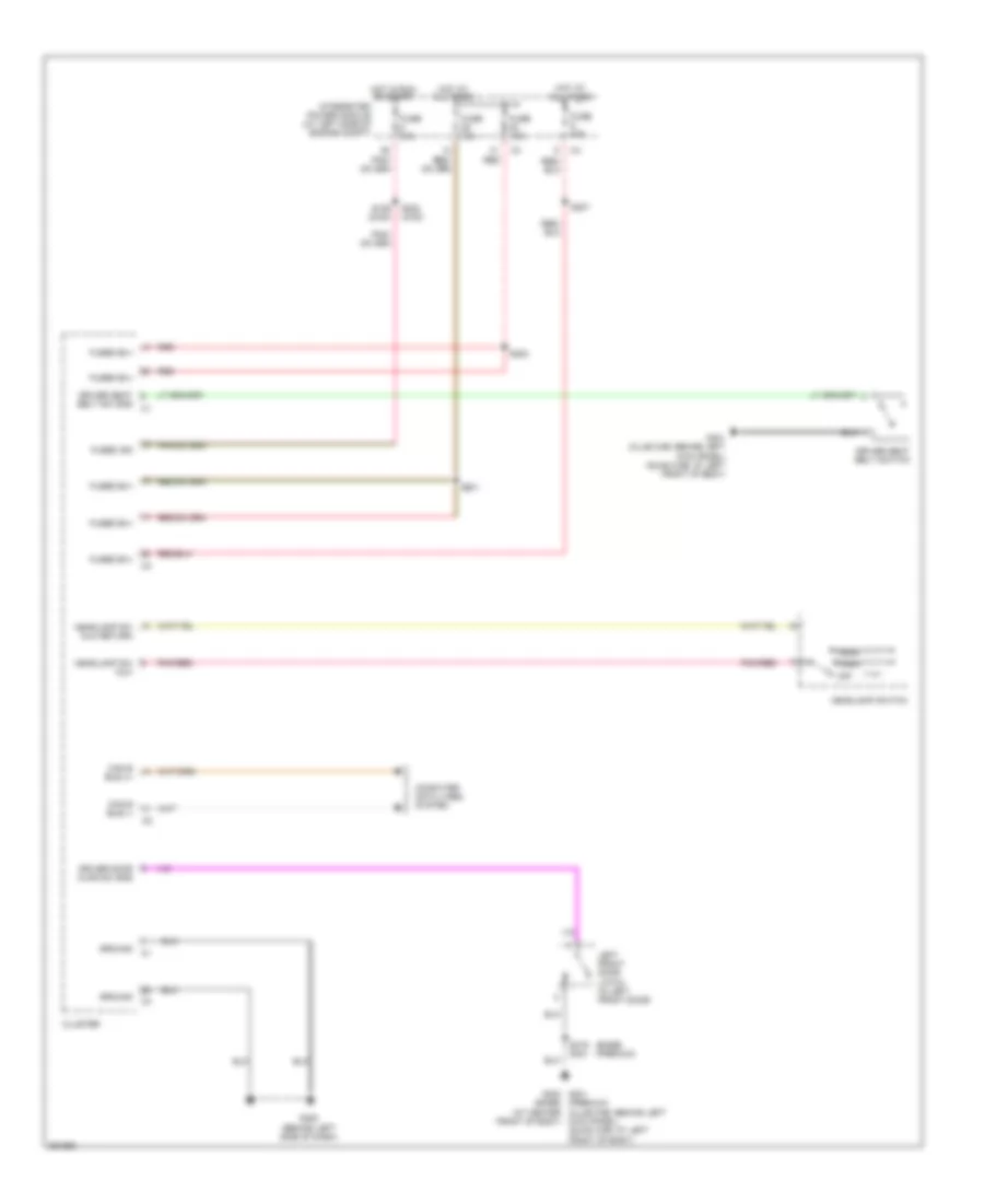
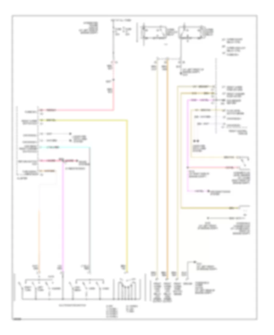
INSTRUMENT CLUSTER
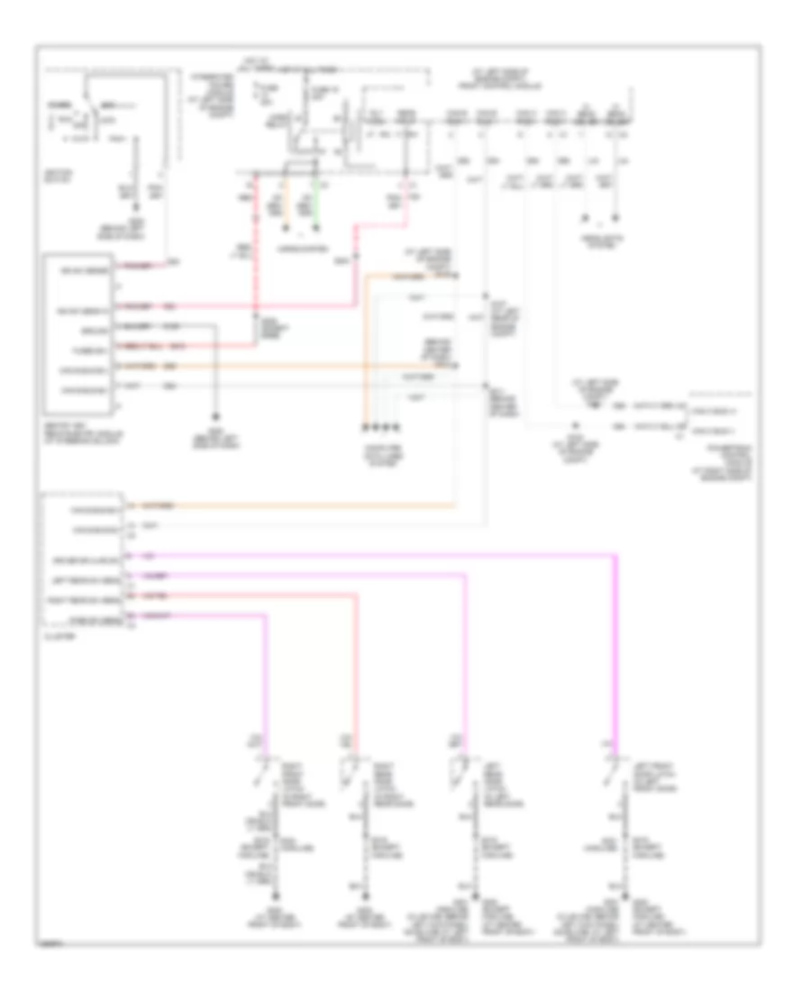
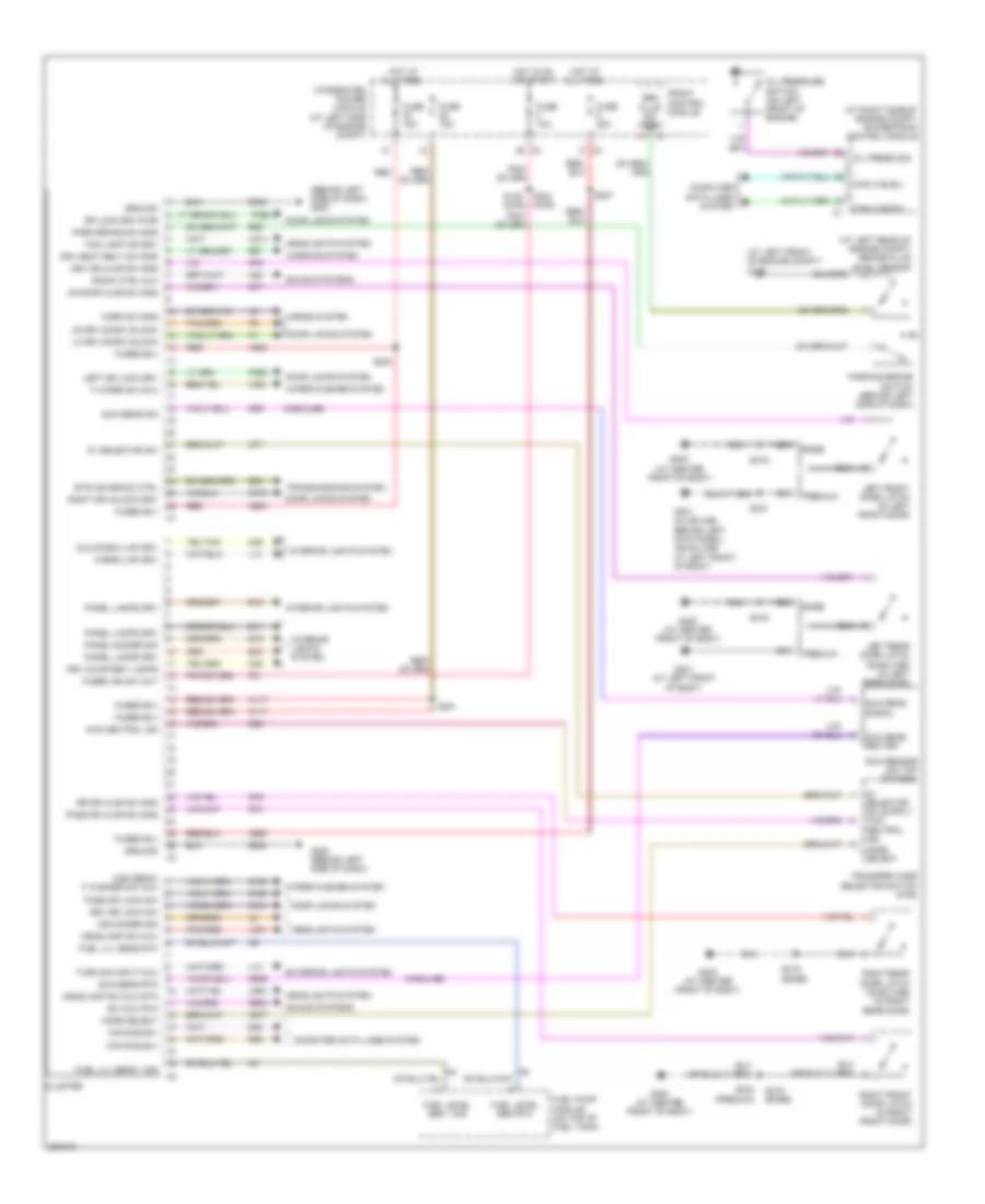
Instrument Cluster Wiring Diagram for Mitsubishi Raider SE 2007
List of elements for Instrument Cluster Wiring Diagram for Mitsubishi Raider SE 2007:
- (at left front of engine compt) g100
- (at left rear of engine compt) brake fluid level sensor
- (at right side of engine compt) powertrain control module
- (behind left side of dash) g200
- (highline)
- 4wd neutral ind
- 5v selector sw
- A117
- A920
- A924
- B25
- B30
- Base
- Brk fluid sw sns
- Btsi solenoid ctrl
- Can b bus(+)
- Can b bus(-)
- Can c bus(+)
- Can c bus(-)
- Cargo lmp drv
- Cluster
- Computer data lines system
- D54
- D55
- Door locks system
- Dr lock drv r dr
- Drv courtesy lamps
- Drv dr ajar sw sns
- Drv dr lock sw
- Drv seat belt sw sns
- E11
- E12
- E19
- E33
- Exterior lights system
- F washer sw mux
- F wiper sw mux
- F21
- Fog lamp ind drv
- Front control module
- Fuel level sen 1 sig
- Fuel level sen rtn
- Fuel lvl sens 1 sig
- Fuel lvl sens rtn
- Fuel pump module (on top of fuel tank)
- Fuse 10a
- Fuse 15a
- Fuse 20a
- Fused b(+)
- Fused ign sw out
- G160
- G161
- G194
- G200 (behind left side of dash)
- G300 (at center front of body)
- G301 (at left front of body)
- G301 (club cab: behind left kick panel) (quad cab: at left front of body)
- G39
- G74
- G75
- G76
- G77
- G778
- G902
- G939
- G95
- Glove box lmp drv
- Ground
- Headlamp sw mux
- Headlamp sw mux rtn
- Headlights system
- High beam/
- Horn sw sns
- Horns system
- Hot at all times
- Hot in on or start
- Ind dimmer sig
- Integrated power module (at left side of engine compt)
- Interior lights system
- K77
- K977
- L12
- L14
- L307
- L900
- L914
- Left dr lock drv
- Left front door latch (in left front door)
- Left rear door latch (quad cab) (in left rear door)
- Lf drv door unlock
- Lr door ajar sw sns
- Lr drv door unlock
- M22
- M28
- Mode select
- Oil press sig
- Oil pressure switch (on left front of engine)
- P392
- P393
- Panel dimmer sig
- Panel lamps drv
- Park brake sw sns
- Parking brake switch (behind left side of dash)
- Pass dr ajar sw sns
- Pass dr lock sw
- Pnk/red
- Premium
- R57
- Radio ctrl mux
- Red
- Right dr unlock drv
- Right front door latch (in right front door)
- Right rear door latch (quad cab) (in right rear door)
- Rr dr ajar sw sns
- S109 (2wd)
- S201
- S202 (4wd)
- S203
- S207
- S319
- S319 (base)
- S321
- S324 (premium)
- Sound systems
- Sun sens return
- Sun sens rtn
- Sun sens sig
- Sun sens signal
- Sun sensor (on top of dash)
- Sw mux rtn
- Transfer case selector switch (4wd)
- Transmissions system
- Turn sig input mux
- W52
- Warning system
- Wiper/washer system
- X20
- Z946
- Z948
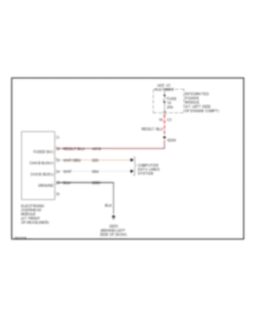
Overhead Console Wiring Diagram for Mitsubishi Raider SE 2007
List of elements for Overhead Console Wiring Diagram for Mitsubishi Raider SE 2007:
- A918
- Can b bus(+)
- Can b bus(-)
- Computer data lines system
- D54
- D55
- Electronic overhead module (at front of headliner)
- Fuse 20a
- Fused b(+)
- G200 (behind left side of dash)
- Ground
- Hot at all times
- Integrated power module (at left side of engine compt)
- S206
- Z993
INTERIOR LIGHTS
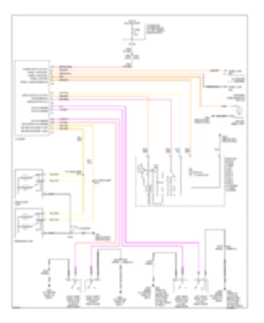
Interior Lights Wiring Diagram for Mitsubishi Raider SE 2007
List of elements for Interior Lights Wiring Diagram for Mitsubishi Raider SE 2007:
- (at headliner) s214
- (at headliner) s215
- A/c heater control
- Center bezel lamp
- Cluster
- Driver courtesy lamp
- Driver glove box lamp
- Drv
- Front dome lamp
- Fuse 10a
- Fused ign sw output
- G200 (behind left side of dash)
- G201 (behind right side of dash)
- G300 (at center front of body)
- G300 (base) (at center front of body)
- G301 (premium) (club cab: behind left kick panel) (quad cab: at left front of body)
- Headlamp sw mux
- Headlamp sw mux rtn
- Headlamp switch 1) head 2) park 3) off 4) dim 1 5) dim 2 6) dim 3 7) dim 4 8) dim 5 9) dim 6 10) parade 11) dome 12) cargo
- Hot in run or start
- Ind dimmer sig
- Integrated power module (at left side of engine compt)
- Left front door latch (in left front door)
- Left rear door latch (quad cab) (in left rear door)
- Panel lamp
- Panel lamp drv
- Panel lamps dimmer sig
- Panel lamps drv
- Pnk/ red
- Pnk/red
- Rear dome lamp
- Right front door latch (in right front door)
- Right rear door latch (quad cab) (in right rear door)
- Rr ajar switch sense
- S109 (2wd)
- S202 (4wd)
- S216
- S319 (base)
- S321 (premium)
- S324 (premium)
- Switch illumination
- Switch sense
- Transfer case selector switch
- W/ sunroof
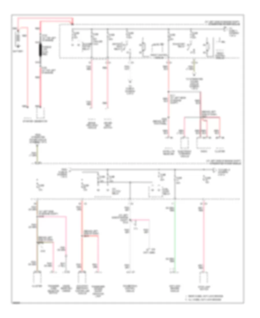
POWER DISTRIBUTION
Power Distribution Wiring Diagram (1 of 3) for Mitsubishi Raider SE 2007
List of elements for Power Distribution Wiring Diagram (1 of 3) for Mitsubishi Raider SE 2007:
- (at left side of engine compt) integrated power module
- (at left side of engine compt) s104
- (at left side of engine compt) s109
- (behind left side of dash) s202
- (behind left side of dash) s207
- (behind left side of dash) s210
- (not used)
- 3.7l
- 4wd
- A/c clutch relay
- All wheel anti-lock brakes
- Anti-lock brakes module
- Battery
- Blower motor relay
- Brake provision module
- C20
- Cluster
- Driver seat switch
- Electronic overhead module
- From fuse 26 (diagram 1 of 3)
- From integrated power module (diagram 1 of 3)
- Front control module
- Fuel pump relay
- Fuse 10a
- Fuse 15a
- Fuse 20a
- Fuse 30a (trailer tow)
- Fuse 40a
- Fuse 50a
- Fusible link (8 ga- red)
- Generator
- Ignition run relay
- Inside rearview mirror
- Ipm
- Nca
- Occupant restraint controller module
- Of engine compt)
- Passenger air bag on/off indicator lamp
- Powertrain control module
- Radio
- Rear wheel anti-lock brakes
- Red
- Run/start relay
- S129 (at top left of engine)
- S130 (at top left of engine)
- S305 (behind left kick panel)
- Satellite receiver
- Starter
- Stop lamp switch
- Tan/ red
- To fuse 10 (diagram 2 of 3)
- To fuse 11 (diagram 1 of 3)
- To fuse 61 (diagram 2 of 3)
- To integrated power module (diagram 1 of 3)
- Transfer case selector switch
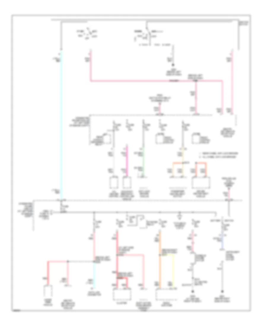
Power Distribution Wiring Diagram (2 of 3) for Mitsubishi Raider SE 2007
List of elements for Power Distribution Wiring Diagram (2 of 3) for Mitsubishi Raider SE 2007:
- (at left side of engine compt) s103
- (behind left side of dash) s204
- (behind left side of dash) s206
- (behind right side of dash) s213
- (diagram 1 of 3)
- (diagram 3 of 3)
- A/c heater control
- Acc
- All wheel anti-lock brakes
- Anti-lock brakes module
- Battery
- Cluster
- Console power outlet
- Data link connector
- Driver heated seat module
- From
- From fuse 19 i
- From splice s132 (diagram 3 of 3)
- Front control module
- Fuse 10a
- Fuse 20a
- Fuse 25a
- Fuse 30a
- G200 (behind left side of dash)
- G201 (behind right side of dash)
- G300 (at center front of body)
- Hands free module
- Ignition
- Ignition run relay
- Ignition switch
- Instrument panel power outlet
- Integrated power module (at left side of engine compt)
- Ipm
- Lock
- Occupant restraint controller module
- Off
- Passenger heated seat switch
- Radio amplifier
- Rear wheel anti-lock brakes
- Rear window defogger relay
- Red
- Red (behind left side of dash) s202
- Red/ tan
- Run
- S218
- Sentry key remote entry/wcm module
- Shift motor/ mode sensor assembly (4wd)
- Start
- Starter relay
- Tan/ pnk
- To fuse 24
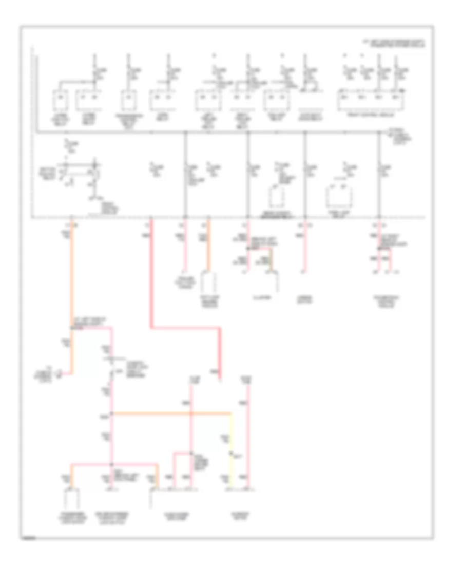
Power Distribution Wiring Diagram (3 of 3) for Mitsubishi Raider SE 2007
List of elements for Power Distribution Wiring Diagram (3 of 3) for Mitsubishi Raider SE 2007:
- (at left side of engine compt) integrated power module
- (at left side of engine compt) s132
- (behind left side of dash) s201
- (trailer tow)
- 20a
- Anti-lock brakes module
- Auto shut down relay
- B(+)
- Club cab
- Cluster
- Driver express window/ door lock switch
- Fog lamp relay
- From fuse 21 (diagram 2 of 3)
- Front control module
- Fuse 15a
- Fuse 15a (trailer tow)
- Fuse 20a
- Fuse 20a (fog lamps)
- Fuse 25a
- Fuse 30a
- Fuse 30a (trailer tow)
- Fuse 40a
- Fuse 40a (except base)
- Horn relay
- Ignition run-acc relay
- Ipm
- Kick panel)
- Left trailer tow relay
- Mirror switch
- Park lamp relay
- Passenger window/ door lock swich
- Powertrain control module
- Quad cab
- Rear window defogger relay
- Red
- Red (at right rear of engine comp) s133
- Right trailer tow relay
- S217
- S220
- S330 (under driver seat)
- Subwoofer amplifier
- Sunroof motor
- Tan/ red
- To fuse 22 (diagram 2 of 3)
- Trailer tow 7-way wiring
- Transmission control relay (a/t)
- Window/ door lock circuit breaker
- Wiper high/low relay
- Wiper on/off relay
POWER DOOR LOCKS
Power Door Locks Wiring Diagram for Mitsubishi Raider SE 2007
List of elements for Power Door Locks Wiring Diagram for Mitsubishi Raider SE 2007:
- (at center of body)
- (quad cab) s306
- 20a
- Cluster
- Driver express window/door lock switch (quad cab) driver window/ door lock switch (club cab)
- Driver right doors
- Dvr dr lck sw mux
- Fused ign sw out (run-acc)
- G300 (at center front of body)
- G300 (base) (at center front of body)
- G301 (club cab: behind left kick panel) (quad cab: at left front of body)
- G301 (premium) (behind left kick panel)
- Gnd
- Hot in on or acc
- Left doors
- Left front
- Left front door latch (in left front door)
- Left rear
- Left rear door latch (quad cab) (in left rear door)
- Pass door lock sw mux
- Passenger window/ door lock switch
- Right front door latch (in right front door)
- Right rear door latch (quad cab) (in right rear door)
- Rr ajar switch sens
- S301
- S307 (quad cab)
- S311 (quad cab) (at left front of body)
- S319 (base)
- S321
- S321 (premium)
- S322
- S324 (premium)
- Sw mux
- Switch mux
- Switch sens
- Window/ door lock circuit breaker (at junction block)
POWER MIRRORS
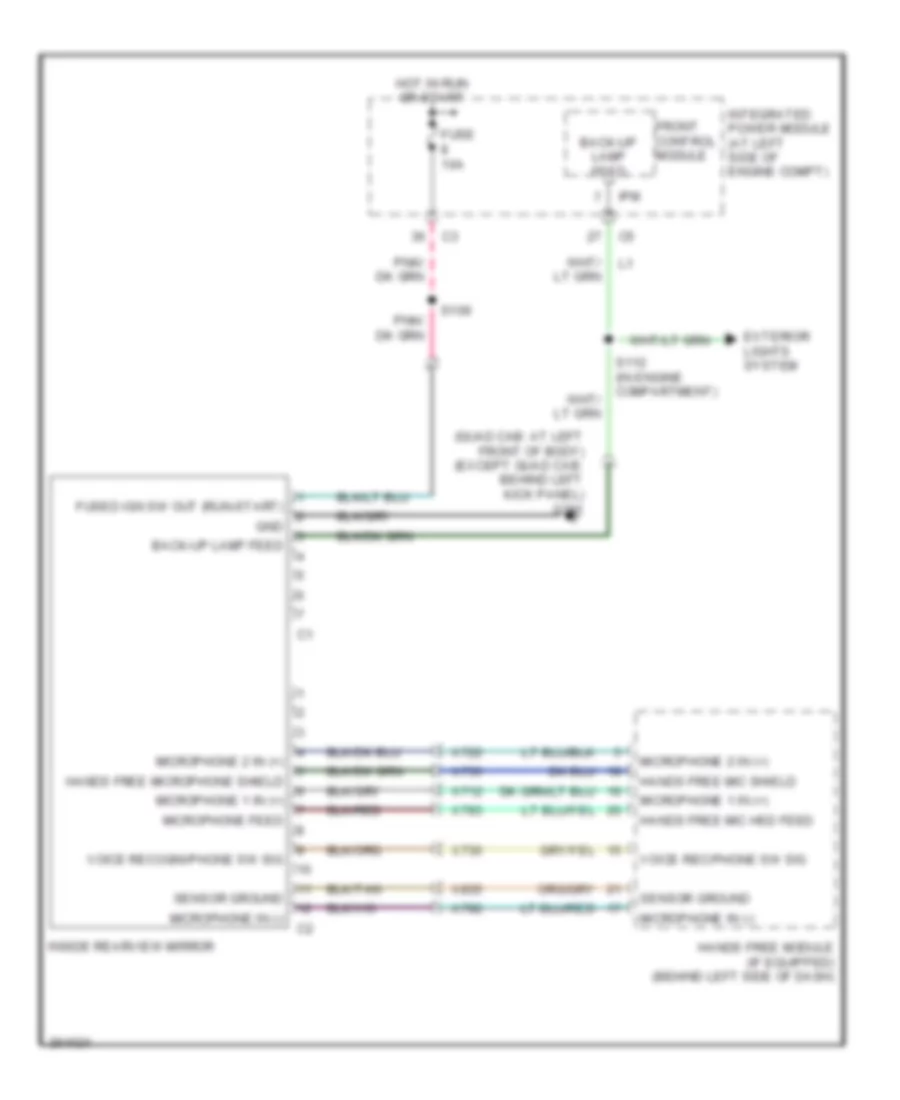
Automatic Day/Night Mirror Wiring Diagram for Mitsubishi Raider SE 2007
List of elements for Automatic Day/Night Mirror Wiring Diagram for Mitsubishi Raider SE 2007:
- (quad cab: at left front of body) (except quad cab: behind left kick panel) g301
- Back-up lamp feed
- Exterior lights system
- Front control module
- Fuse 10a
- Fused ign sw out (run-start)
- Gnd
- Hands free mic hsd feed
- Hands free mic shield
- Hands free microphone shield
- Hands free module (if equipped) (behind left side of dash)
- Hot in run or start
- Inside rearview mirror
- Integrated power module (at left side of engine compt)
- Ipm
- Microphone 1 in (+)
- Microphone 2 in (+)
- Microphone feed
- Microphone in (-)
- S109
- S112 (in engine compartment)
- Sensor ground
- Voice rec/phone sw sig
- Voice recogni/phone sw sig
- X712
- X722
- X730
- X735
- X792
- X793
- X835
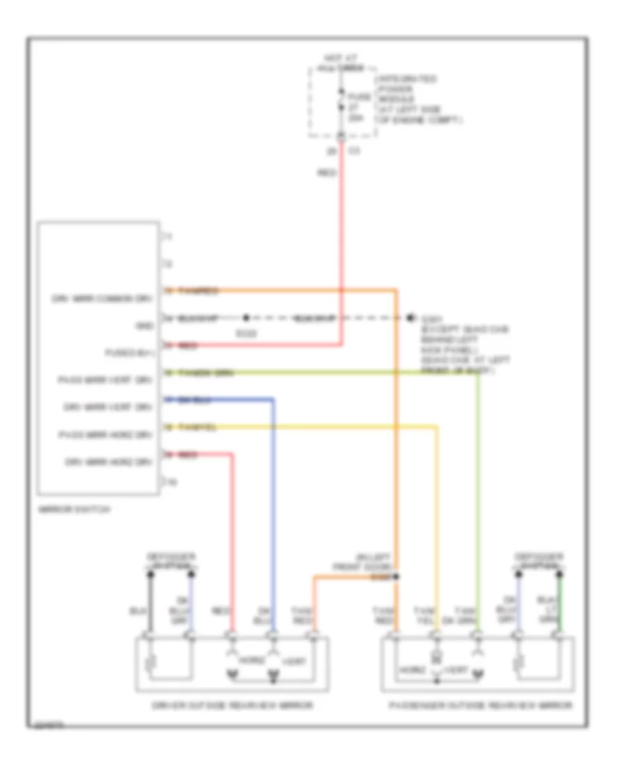
Power Mirrors Wiring Diagram for Mitsubishi Raider SE 2007
List of elements for Power Mirrors Wiring Diagram for Mitsubishi Raider SE 2007:
- (in left front door) s328
- Defogger system
- Driver outside rearview mirror
- Drv mirr common drv
- Drv mirr horz drv
- Drv mirr vert drv
- Fuse 20a
- Fused b(+)
- G301 (except quad cab: behind left kick panel) (quad cab: at left front of body)
- Gnd
- Horiz
- Hot at all times
- Integrated power module (at left side of engine compt)
- Mirror switch
- Pass mirr horz drv
- Pass mirr vert drv
- Passenger outside rearview mirror
- Red
- S322
- Tan/ red
- Tan/red
- Vert
POWER SEATS
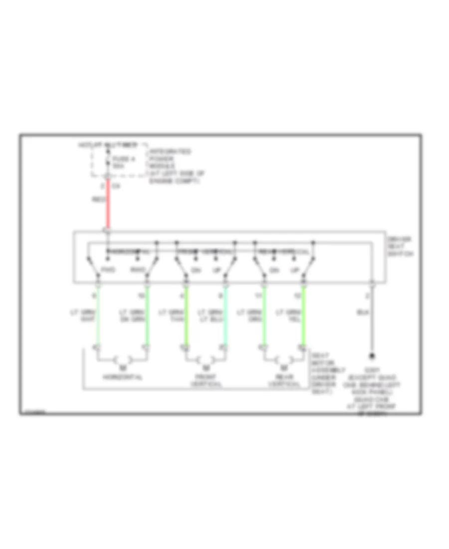
Driver Power Seat Wiring Diagram for Mitsubishi Raider SE 2007
List of elements for Driver Power Seat Wiring Diagram for Mitsubishi Raider SE 2007:
- Driver seat switch
- Front vertical
- Fuse 4 50a
- Fwd
- G301 (except quad cab: behind left kick panel) (quad cab: at left front of body)
- Horizontal
- Hot at all times
- Integrated power module (at left side of engine compt)
- Rear vertical
- Red
- Rwd
- Seat motor assembly (under driver seat)
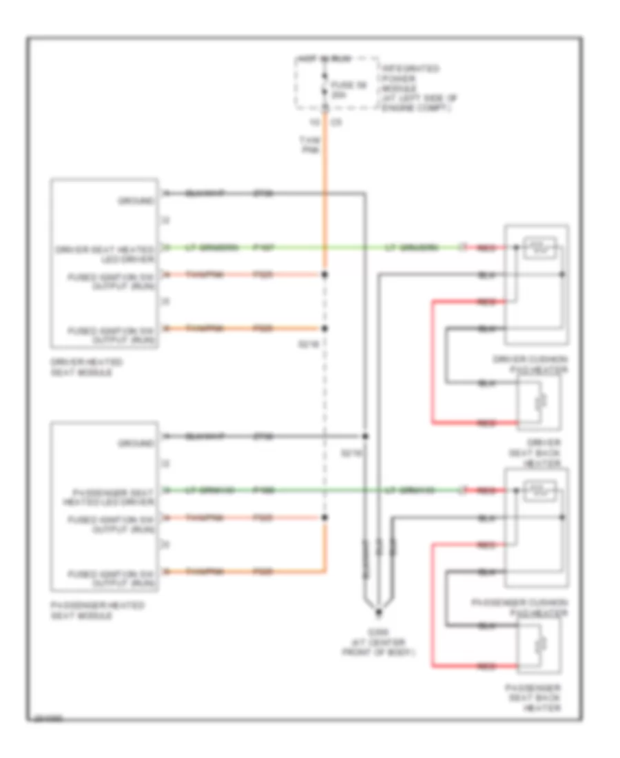
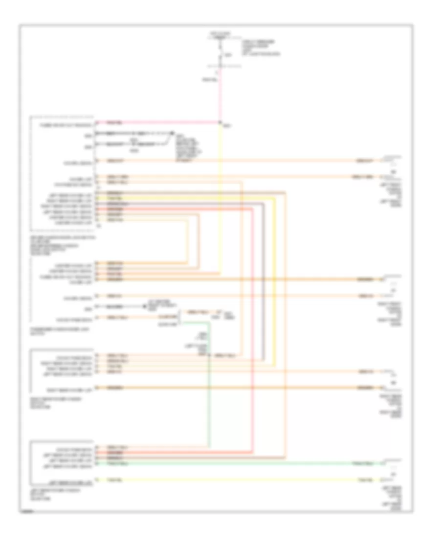
Heated Seats Wiring Diagram for Mitsubishi Raider SE 2007
List of elements for Heated Seats Wiring Diagram for Mitsubishi Raider SE 2007:
- Driver cushion pad heater
- Driver heated seat module
- Driver seat back heater
- Driver seat heated led driver
- F525
- Fuse 58 20a
- Fused ignition sw output (run)
- G300 (at center front of body)
- Ground
- Hot in run
- Integrated power module (at left side of engine compt)
- P187
- P188
- Passenger cushion pad heater
- Passenger heated seat module
- Passenger seat back heater
- Passenger seat heated led driver
- Red
- S218
- S219
- Tan/ pnk
- Tan/pnk
- Z738
POWER TOP/SUNROOF
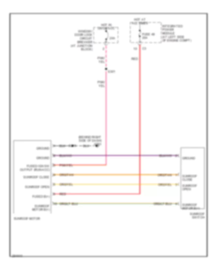
Power Top/Sunroof Wiring Diagram for Mitsubishi Raider SE 2007
List of elements for Power Top/Sunroof Wiring Diagram for Mitsubishi Raider SE 2007:
- (behind right side of dash) g201
- 20a
- Fuse 48 20a
- Fused b(+)
- Fused ign sw output (run-acc)
- Ground
- Hot at all times
- Hot in on or acc
- Integrated power module (at left side of engine compt)
- Red
- S216
- S301
- Sunroof close
- Sunroof motor
- Sunroof motor b(+)
- Sunroof open
- Sunroof switch
- Window/ door lock circuit breaker (at junction block)
POWER WINDOWS
Power Windows Wiring Diagram for Mitsubishi Raider SE 2007
List of elements for Power Windows Wiring Diagram for Mitsubishi Raider SE 2007:
- (at center front of body) g300
- (left floor pan) s327
- (not used)
- 20a
- C302
- Circuit breaker window/door lock (at junction block)
- Club cab
- Driver window/door lock switch (club cab) driver express window/ door lock switch (quad cab)
- Fused ign sw out (run-acc)
- G301 (club cab: behind left kick panel) (quad cab: at left front of body)
- Gnd
- Hot in acc or on
- Left front window motor (in left front door)
- Left rear power window switch (quad cab)
- Left rear win drv (down)
- Left rear win drv (up)
- Left rear window motor (in left rear door)
- Master win sw (down)
- Master win sw (up)
- Passenger window/door lock switch
- Quad cab
- Right front window motor (in right front door)
- Right rear power window switch (quad cab)
- Right rear win drv (down)
- Right rear win drv (up)
- Right rear window motor (in right rear door)
- S301
- S321
- S322
- Wid sw pass down
- Win drv (down)
- Win drv (up)
- Win pass sw (down)
RADIO
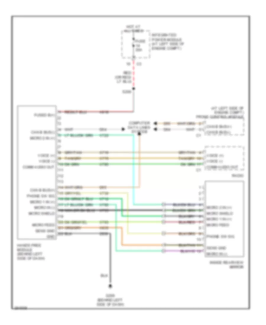
Hands Free Module Wiring Diagram for Mitsubishi Raider SE 2007
List of elements for Hands Free Module Wiring Diagram for Mitsubishi Raider SE 2007:
- (at left side of engine compt) front control module
- A918
- Can b bus(+)
- Can b bus(-)
- Comm audio out
- Computer data lines system
- D54
- D55
- Fuse 20a
- Fused b(+)
- G200 (behind left side of dash)
- Gnd
- Hands free module (behind left side of dash)
- Hot at all times
- Inside rearview mirror
- Integrated power module (at left side of engine compt)
- Micro 1 in (+)
- Micro 2 in (+)
- Micro feed
- Micro in (-)
- Micro shield
- Nca
- Phone sw sig
- Radio
- S206
- Sens gnd
- Voice (+)
- Voice (-)
- X712
- X716
- X722
- X730
- X735
- X776
- X792
- X793
- X795
- X835
- Z939
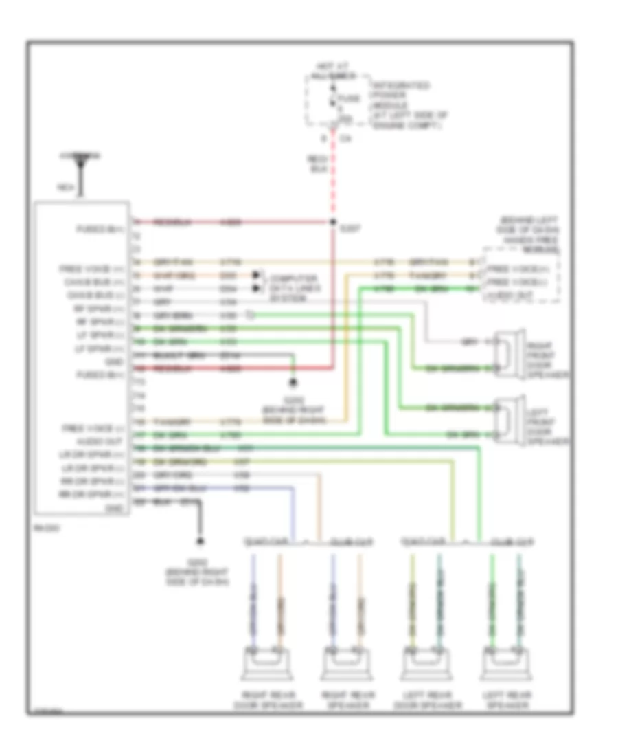
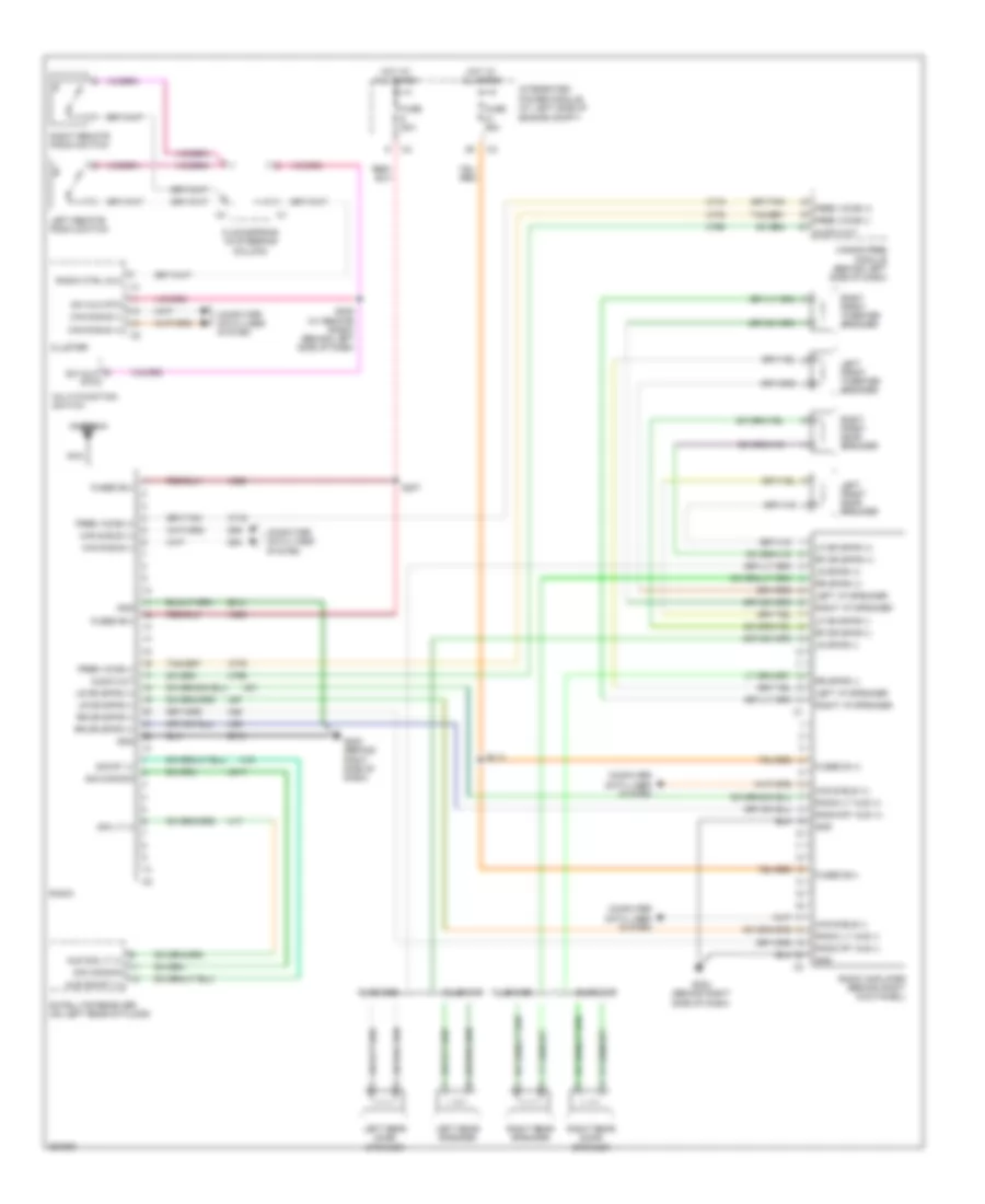
Radio Wiring Diagram, Base for Mitsubishi Raider SE 2007
List of elements for Radio Wiring Diagram, Base for Mitsubishi Raider SE 2007:
- (behind left side of dash) hands free module
- A920
- Antenna
- Audio out
- Can b bus (+)
- Can b bus (-)
- Club cab
- Computer data lines system
- D54
- D55
- Free voice (+)
- Free voice (-)
- Free voice(+)
- Free voice(-)
- Fuse 20a
- Fused b(+)
- G202 (behind right side of dash)
- Gnd
- Hot at all times
- Integrated power module (at left side of engine compt)
- Left front door speaker
- Left rear door speaker
- Left rear speaker
- Lf spkr (+)
- Lf spkr (-)
- Lr dr spkr (+)
- Lr dr spkr (-)
- Nca
- Quad cab
- Radio
- Rf spkr (+)
- Rf spkr (-)
- Right front door speaker
- Right rear door speaker
- Right rear speaker
- Rr dr spkr (+)
- Rr dr spkr (-)
- S207
- X51
- X52
- X53
- X54
- X55
- X56
- X57
- X58
- X716
- X776
- X795
- Z514
- Z515
Radio Wiring Diagram, Premium for Mitsubishi Raider SE 2007
List of elements for Radio Wiring Diagram, Premium for Mitsubishi Raider SE 2007:
- A920
- Antenna
- Aud sig lt (+)
- Aud sig rt (+)
- Audio out
- Can b bus (+)
- Can b bus (-)
- Clockspring (in steering column)
- Club cab
- Cluster
- Computer data lines system
- D54
- D55
- Free voice (+)
- Free voice (-)
- Fuse 20a
- Fuse 25a
- Fused b (+)
- Fused b(+)
- G202 (behind right side of dash)
- Gnd
- Hands free module (behind left side of dash)
- Hot at all times
- Integrated power module (at left side of engine compt)
- Left front door speaker
- Left front tweeter speaker
- Left i/p speaker
- Left rear door speaker
- Left rear speaker
- Left remote radio switch
- Lf dr spkr (+)
- Lf dr spkr (-)
- Lr dr spkr (+)
- Lr dr spkr (-)
- Lr spkr (+)
- Lr spkr (-)
- Multi-function switch
- Nca
- Quad cab
- Radio
- Radio amplifier (behind right kick panel)
- Radio ctrl mux
- Radio lt aud (-)
- Radio rt aud (-)
- Radio-lt aud (+)
- Radio-rt aud (+)
- Rf dr spkr (+)
- Rf dr spkr (-)
- Right front door speaker
- Right front tweeter speaker
- Right i/p speaker
- Right rear door speaker
- Right rear speaker
- Right remote radio switch
- Rr dr spkr (+)
- Rr dr spkr (-)
- Rr spkr (+)
- Rr spkr (-)
- S205 (w/ remote radio) (behind left side of dash)
- S207
- S213
- Satellite receiver (on left rear of floor)
- Sig common
- Sig lt (+)
- Sig rt (+)
- Sw mux rtn
- X16
- X17
- X51
- X52
- X57
- X58
- X716
- X776
- X795
- X917
- Z514
- Z515
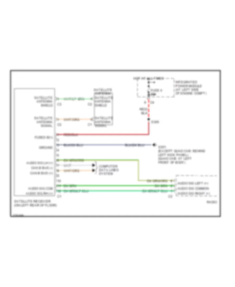
Satellite Radio Wiring Diagram for Mitsubishi Raider SE 2007
List of elements for Satellite Radio Wiring Diagram for Mitsubishi Raider SE 2007:
- Audio sig com
- Audio sig common
- Audio sig left (+)
- Audio sig lh (+)
- Audio sig rh (+)
- Audio sig right (+)
- Can b bus (+)
- Can b bus (-)
- Computer data lines system
- Fuse 6 20a
- Fused b(+)
- G301 (except quad cab: behind left kick panel) (quad cab: at left front of body)
- Ground
- Hot at all times
- Integrated power module (at left side of engine compt)
- Radio
- S305
- Satellite antenna
- Satellite antenna c1 signal
- Satellite antenna c2 shield
- Satellite antenna shield
- Satellite antenna signal
- Satellite receiver (on left rear of floor)
SHIFT INTERLOCK
3.7L
3.7L, Shift Interlock Wiring Diagram for Mitsubishi Raider SE 2007
List of elements for 3.7L, Shift Interlock Wiring Diagram for Mitsubishi Raider SE 2007:
- (near rear of engine) s118
- B25
- B30
- Brake transmission shift interlock solenoid (near steering column)
- Brk sw sens
- Btsi sol ctrl
- Can b bus +
- Can b bus -
- Can c bus +
- Can c bus -
- Cluster
- Computer data lines system
- D54
- D55
- D64
- D65
- Fuse 25a
- G200 (behind left side of dash)
- Hot at all times
- Integrated power module (at left side of engine compt)
- K900
- P/n sns
- Parking brake switch (behind left side of dash)
- Powertrain control module (at right side of engine compt)
- S120
- Sensor gnd
- T41
- T42
- T54
- Trans ctrl
- Trans temp
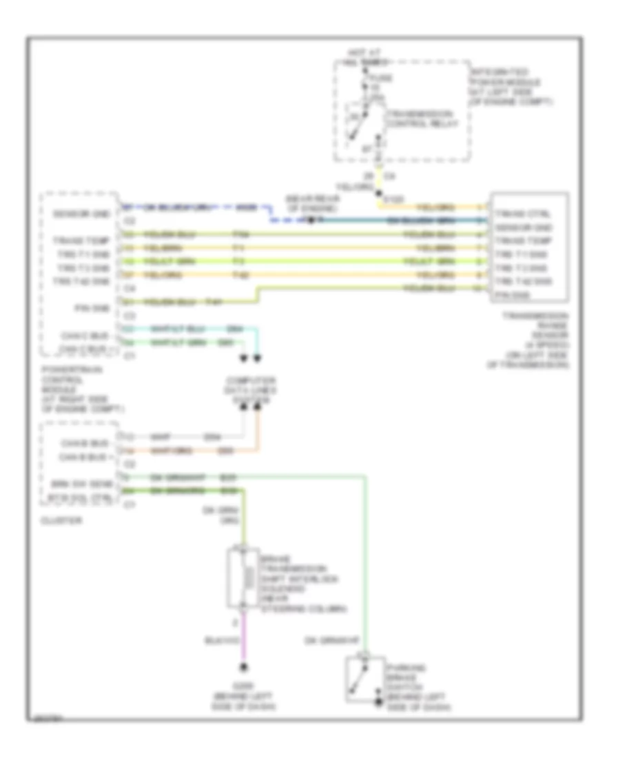
- Transmission control relay
- Transmission range sensor (4 speed) (on left side of transmission)
- Trs t1 sns
- Trs t3 sns
- Trs t42 sns
4.7L
4.7L, Shift Interlock Wiring Diagram for Mitsubishi Raider SE 2007
List of elements for 4.7L, Shift Interlock Wiring Diagram for Mitsubishi Raider SE 2007:
- A919
- B25
- B30
- Brake transmission shift interlock solenoid (near steering column)
- Brk sw sens
- Btsi sol ctrl
- Can b bus +
- Can b bus -
- Can c bus +
- Can c bus -
- Cluster
- Computer data lines system
- D54
- D55
- D64
- D65
- Fuse 20a
- Fused b (+)
- G200 (behind left side of dash)
- Hot at all times
- Integrated power module (at left side of engine compt)
- P/n sns
- Parking brake switch (behind left side of dash
- Powertrain control module (at right side of engine compt)
- Red
- S133
- T41
- T42
- Transmission solenoid/trs assembly (on left side of transmission)
- Trs t1 sns
- Trs t2 temp
- Trs t3 sns
- Trs t42 sns
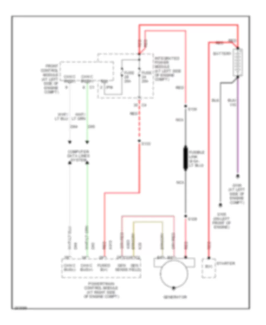
STARTING/CHARGING
Charging Wiring Diagram for Mitsubishi Raider SE 2007
List of elements for Charging Wiring Diagram for Mitsubishi Raider SE 2007:
- A803
- A919
- B(+)
- Battery
- Can c bus(+)
- Can c bus(-)
- Computer data lines system
- D64
- D65
- Front control module (at left side of engine compt)
- Fuse 20a
- Fused b(+)
- G105 (on left front of engine)
- G106 (at left side of engine compt)
- Gen field
- Gen sense
- Generator
- Integrated power module (at left side of engine compt)
- Ipm
- K20
- Nca
- Powertrain control module (at right side of engine compt)
- Red
- S129
- S130
- S133
- Starter
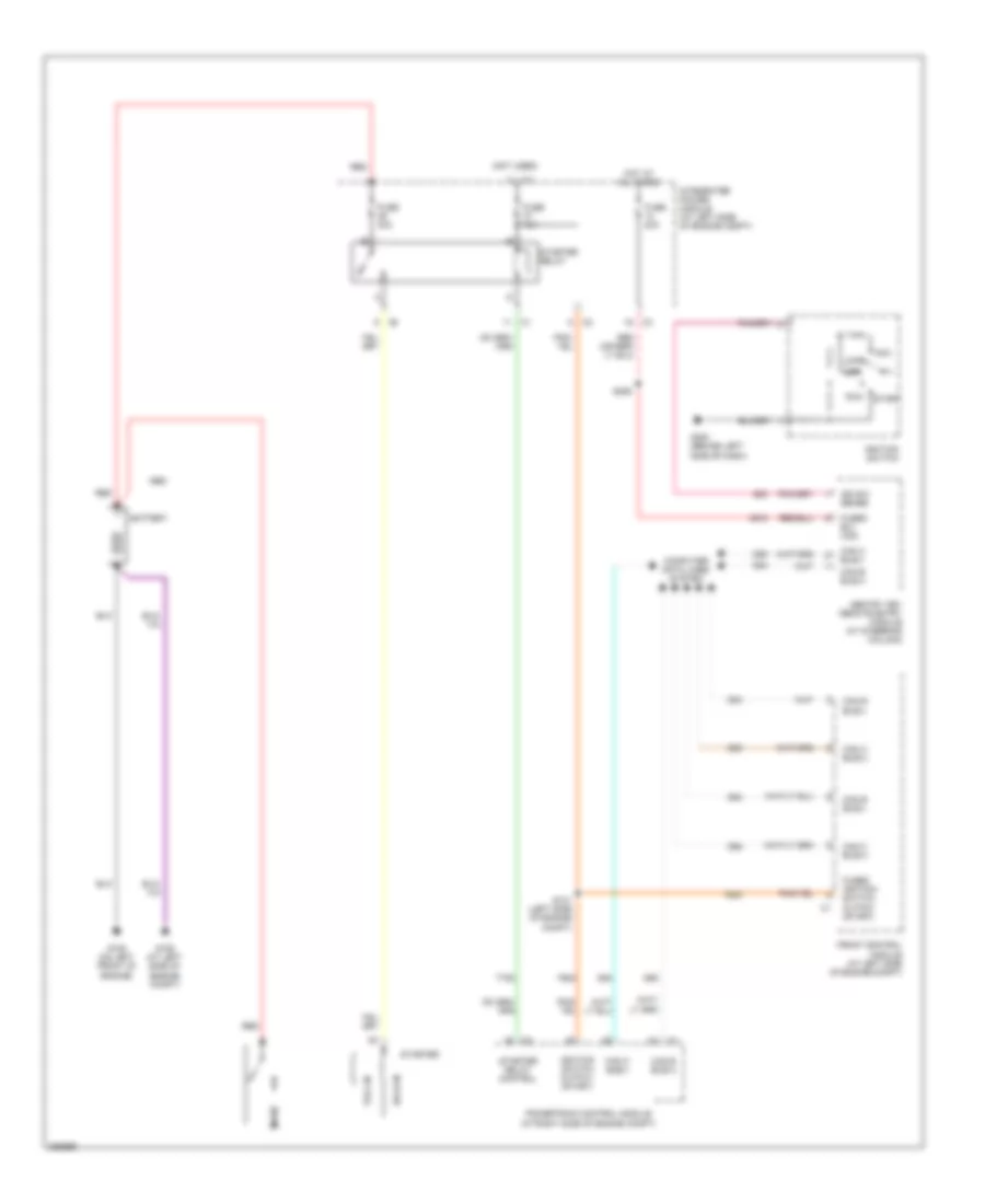
Starting Wiring Diagram for Mitsubishi Raider SE 2007
List of elements for Starting Wiring Diagram for Mitsubishi Raider SE 2007:
- (not used)
- A918
- Acc
- Battery
- Can b bus(+)
- Can b bus(-)
- Can c bus(+)
- Can c bus(-)
- Computer data lines system
- D54
- D55
- D64
- D65
- F924
- Front control module (at left side of engine compt)
- Fuse 10a
- Fuse 20a
- Fuse 30a
- Fused b(+) (iod)
- Fused ignition switch output (start)
- G105 (on left front of engine)
- G106 (at left side of engine compt)
- G20
- G200 (behind left side of dash)
- Hold-in
- Hot at all times
- Ign sw sense
- Ignition switch
- Ignition switch output (start)
- Integrated power module (at left side of engine compt)
- Lock
- Off
- Powertrain control module (at right side of engine compt)
- Pull-in
- Red
- Run
- S131 (left side of engine compt)
- S206
- Sentry key remote entry module (at steering column)
- Start
- Starter
- Starter relay
- Starter relay control
- T752
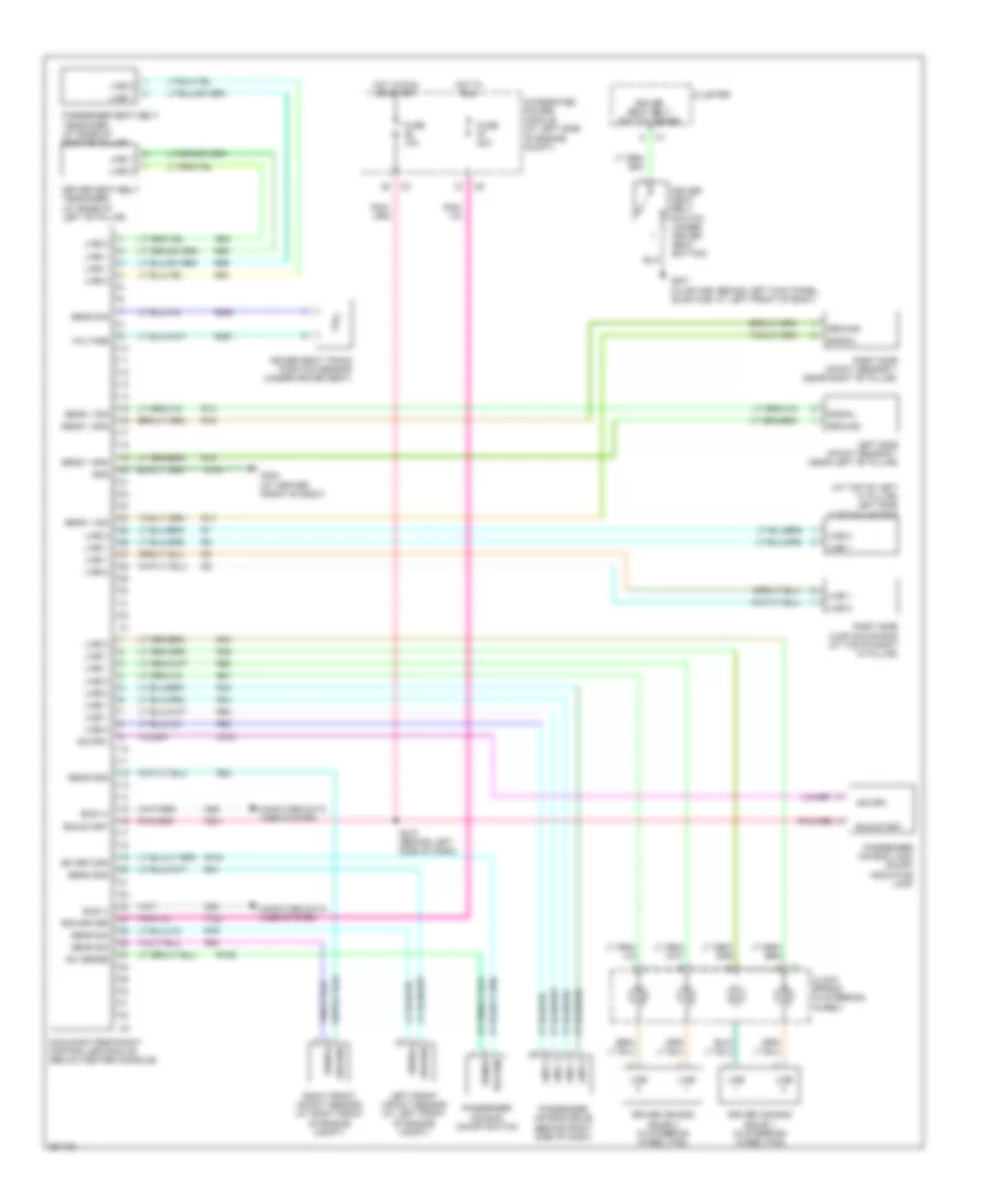
SUPPLEMENTAL RESTRAINTS
Supplemental Restraints Wiring Diagram for Mitsubishi Raider SE 2007
List of elements for Supplemental Restraints Wiring Diagram for Mitsubishi Raider SE 2007:
- (at top of left "a" pillar) left side curtain air bag
- Bus (+)
- Bus (-)
- Clock spring (in steering wheel)
- Cluster
- Computer data lines system
- D54
- D55
- Driver air bag squib 1 (in steering wheel pad)
- Driver air bag squib 2 (in steering wheel pad)
- Driver seat belt switch (under driver seat bottom)
- Driver seat belt switch sense
- Driver seat belt tensioner (at base of left "b" pillar)
- Driver seat track position sensor (under driver seat)
- F100
- F201
- Fuse 10a
- Fuse 20a
- G104
- G300 (at center front of body)
- G301 (club cab: behind left kick panel, quad cab: at left front of body)
- Gnd
- Ground
- Hot in run
- Hot in run or start
- Ind drv
- Indicator lamp
- Integrated power module (at left side of engine compt)
- Left front impact sensor (at left front of engine compt)
- Left side impact sensor 1 (near left "b" pillar)
- Line
- Line 1
- Line 2
- Occupant restraint controller module (below center console)
- Passenger air bag lamp on/off
- Passenger air bag on/off switch
- Passenger air bag squib (behind right side of dash)
- Passenger seat belt tensioner (at base of right"b" pillar)
- R104
- R106
- R13
- R14
- R15
- R16
- R261
- R263
- R42
- R43
- R44
- R45
- R53
- R54
- R55
- R56
- R61
- R62
- R63
- R64
- R79
- R80
- R81
- R82
- Return
- Right front impact sensor (at right front of engine compt)
- Right side curtain air bag (at top of right "a" pillar)
- Right side impact sensor 1 (near right "b" pillar)
- Run driver
- Run-start
- S210 (behind left side of dash)
- Sens 1 gnd
- Sens 1 sig
- Sens gnd
- Sens sig
- Sense
- Signal
- Sw return
- Sw sense
- Voltage
- Z104
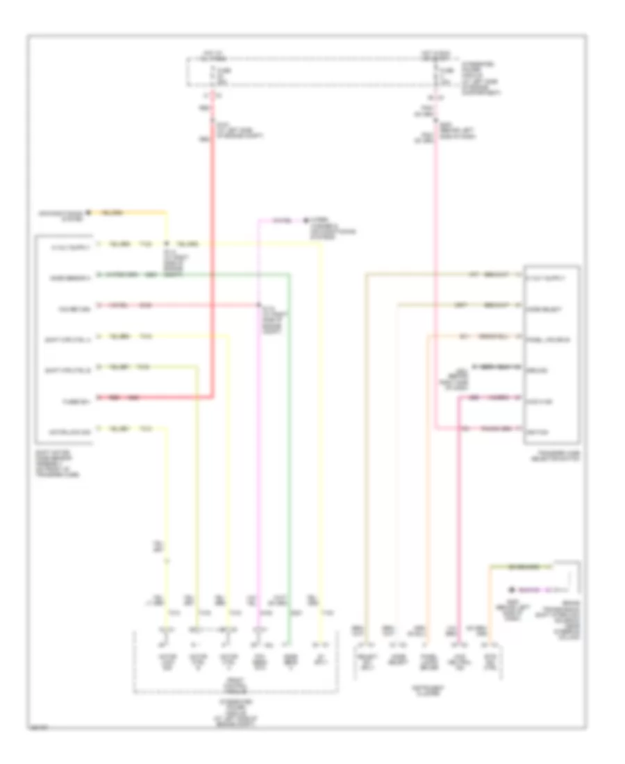
TRANSMISSION
Transfer Case Wiring Diagram, 4WD for Mitsubishi Raider SE 2007
List of elements for Transfer Case Wiring Diagram, 4WD for Mitsubishi Raider SE 2007:
- 4wd n ind
- 4wd neutral ind
- 5v sply
- A924
- Air conditioning system
- Brake transmission shift interlock solenoid (near steering column)
- Btsi sol ctrl
- D201
- E11
- F21
- Fcm return
- Fcm sens rtn
- Front control module
- Fuse 10a
- Fuse 20a
- Fused b(+)
- G180
- G200 (behind left side of dash)
- G201 (behind right side of dash)
- G95
- Ground
- Hot at all times
- Hot in run or start
- Ignition
- Instrument cluster
- Integrated power module (at left side of engine compartment)
- Integrated power module (at left side of engine compt)
- Ipm
- K77
- K977
- Mode select
- Mode sens a
- Mode sensor a
- Motor ctrl a
- Motor ctrl b
- Motor lock sig
- Panel lamps driver
- Panel lps drvr
- Red
- S103 (at left side of engine compt)
- S114 (at right side of engine compt)
- S115 (at right side of engine compt)
- S202 (behind left side of dash)
- Select sw sply
- Shift motor/ mode sensor assembly (on front of transfer case)
- Shift mtr ctrl a
- Shift mtr ctrl b
- T103
- T313
- T315
- T316
- Transfer case selector switch
- Wiper/ washer & air conditioning systems
- Z973
3.7L
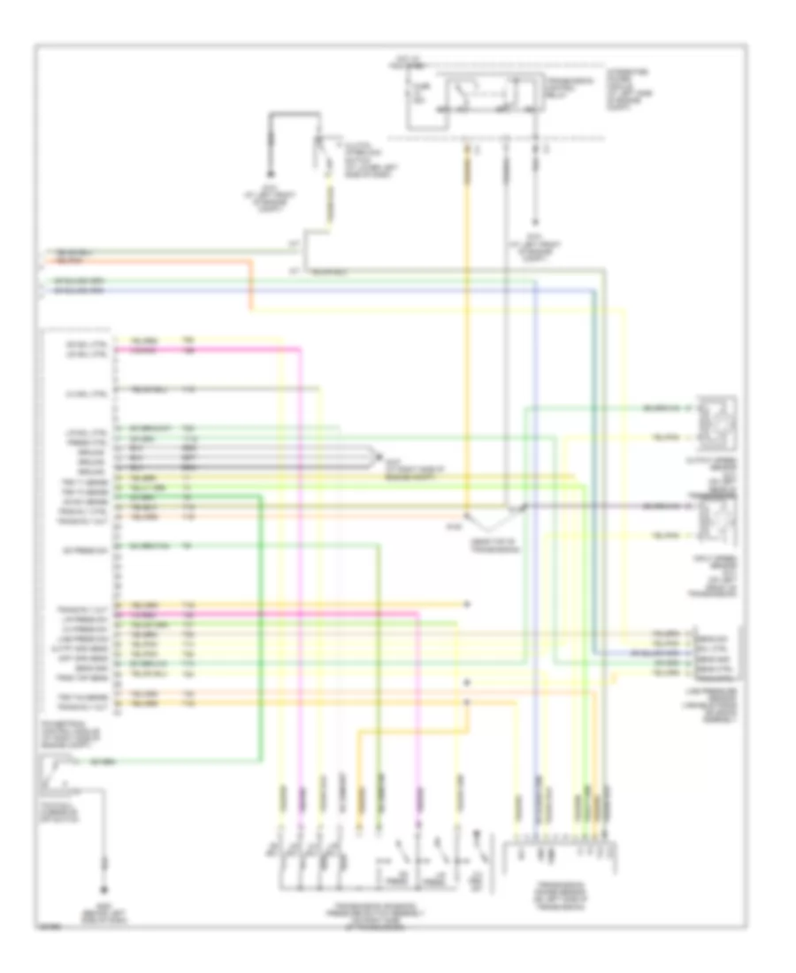
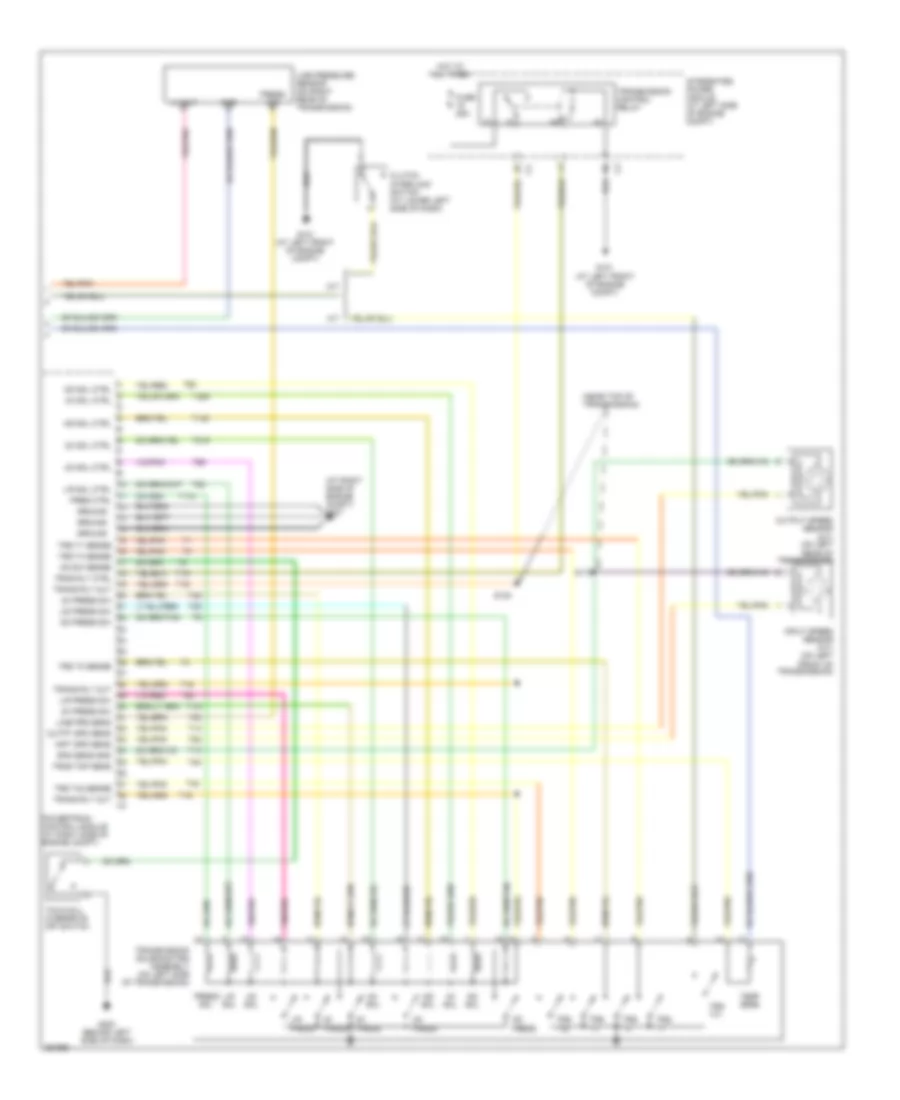
3.7L, A/T Wiring Diagram for Mitsubishi Raider SE 2007
List of elements for 3.7L, A/T Wiring Diagram for Mitsubishi Raider SE 2007:
- (at top right of engine) s124
- (near top of transmission)
- 2-4 press sw
- 2-4 prs sw
- 2-4 sol
- 2-4 sol ctrl
- 5 vol
- Engine controls system
- F856
- Fuse 25a
- G101 (at left front of engine compt)
- G107 (at right side of engine compt)
- G200 (behind left side of dash)
- Gnd
- Ground
- Hot at all times
- Inpt spd sens
- Input speed sensor (on left front of transmission)
- Integrated power module (at left side of engine compt)
- K900
- L/r press
- L/r press sw
- L/r sol
- L/r sol ctrl
- Line press
- Line press sig
- Line pressure sensor/ variable force solenoid assembly
- Od press
- Od press sw
- Od sol
- Od sol ctrl
- Od sw sense
- Outpt spd sens
- Output speed sensor (on left rear of transmission)
- Powertrain control module (at right side of engine compt)
- Press ctrl
- Press strl
- Red
- Rly
- S118 (near rear of engine)
- S119
- S120
- Sens grd c2
- Sensor gnd
- Spd sens gnd
- T118
- T13
- T14
- T15
- T16
- T19
- T20
- T38
- T41
- T42
- T47
- T50
- T52
- T54
- T59
- T60
- Temp
- Tow/haul overdrive off switch
- Tran ctrl
- Trans rly out
- Trans rly out c4
- Transmission control relay
- Transmission range sensor (on left side of transmission)
- Transmission solenoid/ pressure switch assembly (on right side of transmission)
- Trns rly ctrl
- Trns tmp sens
- Trs t1 sense
- Trs t3 sense
- Trs t41 sense
- Trs t42 sense
- Ud sol
- Ud sol ctrl
- Z904
- Z908
- Z977
4.7L
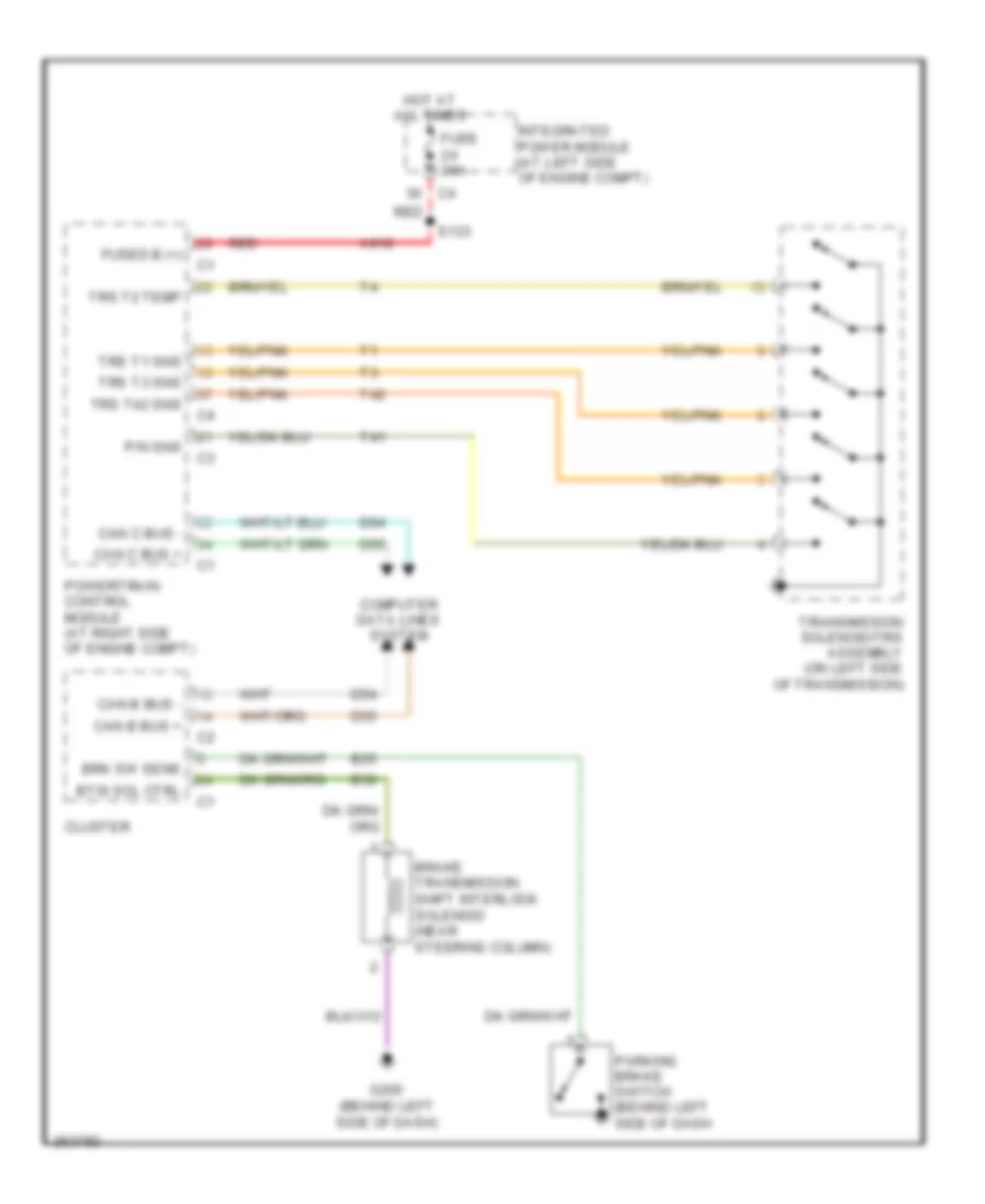
4.7L, A/T Wiring Diagram for Mitsubishi Raider SE 2007
List of elements for 4.7L, A/T Wiring Diagram for Mitsubishi Raider SE 2007:
- (at right side of engine compt) g107
- (near rear of engine) s118
- (near top of transmission)
- 2c press
- 2c press sw
- 2c sol
- 2c sol ctrl
- 4c press
- 4c press sw
- 4c sol
- 4c sol ctrl
- 5 volt
- 5v sply c1
- F856
- Fuse 25a
- G101 (at left front of engine compt)
- G200 (behind left side of dash)
- Gnd
- Ground
- Hot at all times
- Inpt spd sens
- Input speed sensor (on left front of transmission)
- Integrated power module (at left side of engine compt)
- K900
- L/r press
- L/r press sw
- L/r sol
- L/r sol ctrl
- Line pressure sensor (on right rear of transmission)
- Ms sol
- Ms sol ctrl
- Od press
- Od press sw
- Od sol
- Od sol ctrl
- Od sw sense
- Outpt spd sens
- Output speed sensor (on left rear of transmission)
- Powertrain control module (at right side of engine compt)
- Pres ctrl
- Press sens sig
- Press sig
- Press sol
- S119
- S120
- S124 (at top right of engine)
- Sens gnd c2
- Spd sens gnd
- T118
- T13
- T14
- T140
- T147
- T15
- T16
- T20
- T219
- T259
- T29
- T38
- T41
- T42
- T48
- T50
- T52
- T54
- T59
- T60
- Temp sens
- Tow/haul overdrive off switch
- Trans rly out
- Trans rly out c4
- Transmission control relay
- Transmission solenoid/trs assembly (on left side of transmission)
- Trns rly ctrl
- Trns tmp sens
- Trs t1
- Trs t1 sense
- Trs t2
- Trs t2 sense
- Trs t3
- Trs t3 sense
- Trs t41
- Trs t41 sens c3
- Trs t42
- Trs t42 sense
- Ud press
- Ud press sw
- Ud sol
- Ud sol ctrl
- Z904
- Z908
- Z977
WARNING SYSTEMS
Warning Systems Wiring Diagram for Mitsubishi Raider SE 2007
List of elements for Warning Systems Wiring Diagram for Mitsubishi Raider SE 2007:
- (base) (at center front of body)
- (base) (premium)
- Can b bus (+)
- Can b bus (-)
- Cluster
- Computer data lines system
- Driver door ajar sw sns
- Driver seat belt sw sns
- Driver seat belt switch
- Fuse 10a
- Fuse 15a
- Fuse 20a
- Fused b(+)
- Fused ign
- G200 (behind left side of dash)
- G300 g301 (premium) (club cab: behind left kick panel) (quad cab: at left front of body)
- G301 (club cab: behind left kick panel) (quad cab: at left front of body)
- Ground
- Head
- Headlamp sw mux
- Headlamp sw mux return
- Headlamp switch
- Hot at all times
- Hot in run or start
- Integrated power module (at left side of engine compt)
- Left front door latch (in left front door)
- Off
- Park
- Pnk/red
- Red
- S109 (2wd)
- S201
- S202
- S202 (4wd)
- S207
- S319 s321
WIPER/WASHER
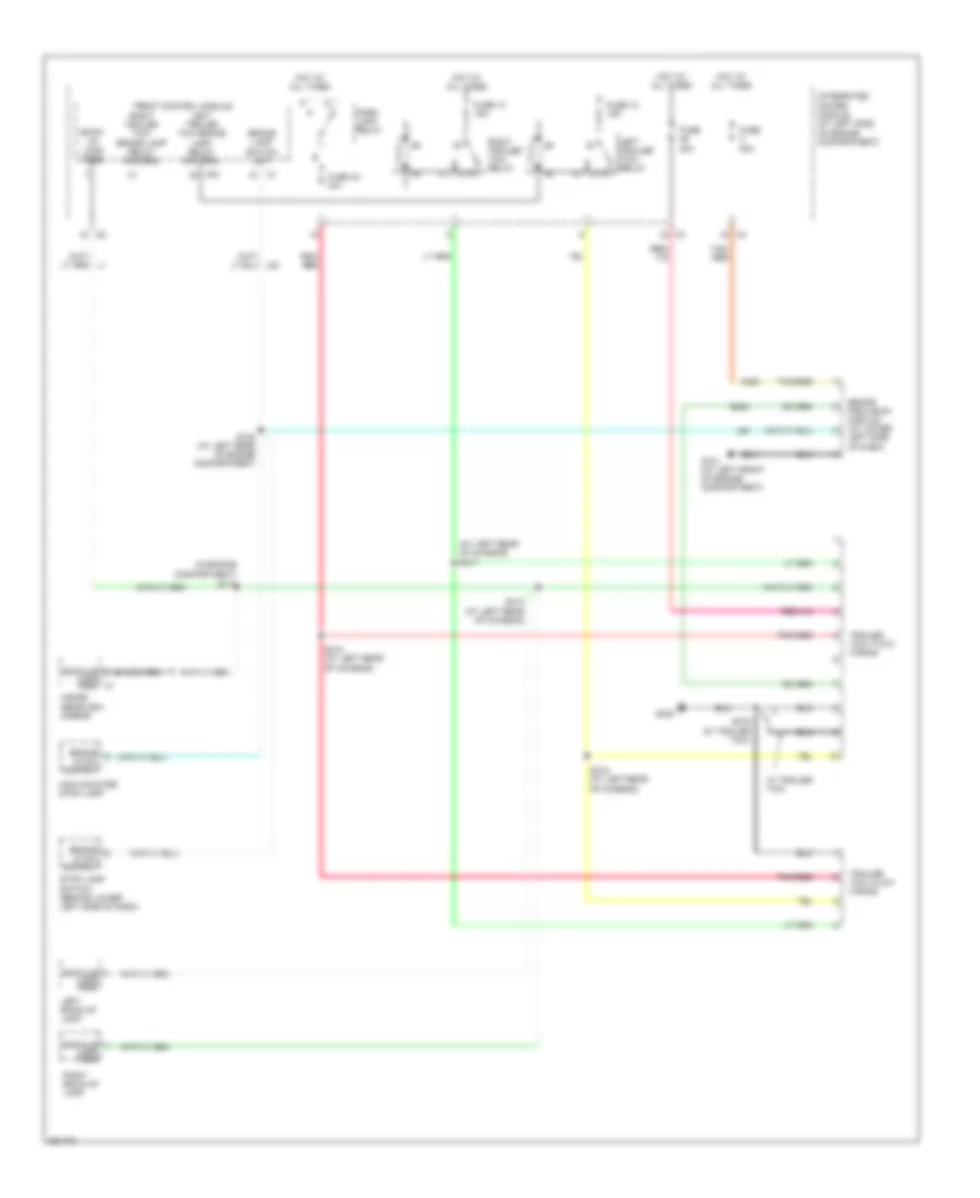
Wiper/Washer Wiring Diagram for Mitsubishi Raider SE 2007
List of elements for Wiper/Washer Wiring Diagram for Mitsubishi Raider SE 2007:
- (at left front of engine compt) g101
- 0) off 1) i/wipe 1 2) i/wipe 2 3) i/wipe 3 4) i/wipe 4
- 5) i/wipe 5 6) low 7) high
- 87a
- Air conditioning system
- Can b bus(+)
- Can b bus(-)
- Cluster
- Computer data lines system
- D54
- D55
- Fcm sensor return ipm
- Fluid level switch sense
- Front control module
- Front washer pump motor
- Front wiper high/ low relay high speed output
- Front wiper high/ low relay low speed output
- Front wiper park sw sns
- Front wiper park switch sense
- Front wiper switch mux
- Fuse 20a
- Fuse 30a
- Fused b(+)
- G100 (at left front of engine compt)
- G101 (at left front of engine compt)
- G180
- Ground
- Hazard
- High beam
- High beam/ front washer switch mux
- Horn
- Hot at all times
- Integrated power module (at left side of engine compt)
- Left turn
- Multifunction switch
- Relay ctrl
- Return switch mux
- Right turn
- S115 (at right side of engine compt)
- S205
- S207
- Sound systems
- Turn signal input mux
- W/ remote radio
- W10
- Wash
- Washer fluid level sensor (at lower right front of engine compt)
- Windshield washer pump (at lower right front of engine compt)
- Windshield wiper motor (at left rear of engine compt)
- Wiper high/low
- Wiper high/low relay
- Wiper on/off
- Wiper on/off relay

 Čeština
 Dansk
Dansk Deutsch
 Ελληνικά
 English
 English
 Suomi
Suomi Français
 Français
 עברית
עברית Hrvatski
 Magyar
 Italiano
 日本語
日本語 한국어
한국어 Nederlands
 Polski
 Português
 Português
 Română
 Русский
 Slovenčina
 Slovenščina
 Svenska
 Türkçe
 中文 (中国)