ACTIVE BODYWORKS
Active Bodyworks Wiring Diagram for Porsche Panamera 4 2013
 https://portal-diagnostov.com/license.html
Automotive Electricians Portal FZCO
Automotive Electricians Portal FZCO
https://portal-diagnostov.com/license.html
https://portal-diagnostov.com/license.html
Automotive Electricians Portal FZCO
Automotive Electricians Portal FZCO
List of elements for Active Bodyworks Wiring Diagram for Porsche Panamera 4 2013:
- 2d spoiler drive
- 2d spoiler hall sensor
- 2d spoiler positive drive (w/ spoiler assembly)
- 2d spoiler positive hall drive (w/ spoiler assembly)
- Can high
- Can low
- Computer data lines system
- Dc ausgang
- Dc/ac converter
- Ext sens +
- Extend mtr +
- Extend mtr -
- Extend spoiler
- Extension rly
- Fuse 10a
- Fuse 30a
- Gnd ext sens
- Hall gnd mtr
- Hall mtr gnd
- Hall sens 1
- Hall sens 2
- Hall sens 3
- Hall sens 4
- Hall sens mtr +
- Hot at all times
- Mb27 (left rear of luggage compt)
- Mtr + hall sens
- Rear bcm (left side of luggage compt)
- Rear fuse box (row a)
- Red
- Retract spoiler
- Retraction rly
- Sens gnd
- Spoiler flap relay (w/ spoiler assembly)
- Term 15
- Term 30tp
- Term 31
- X240
- X242
- X730
- X730-1a1
- X730-1b1
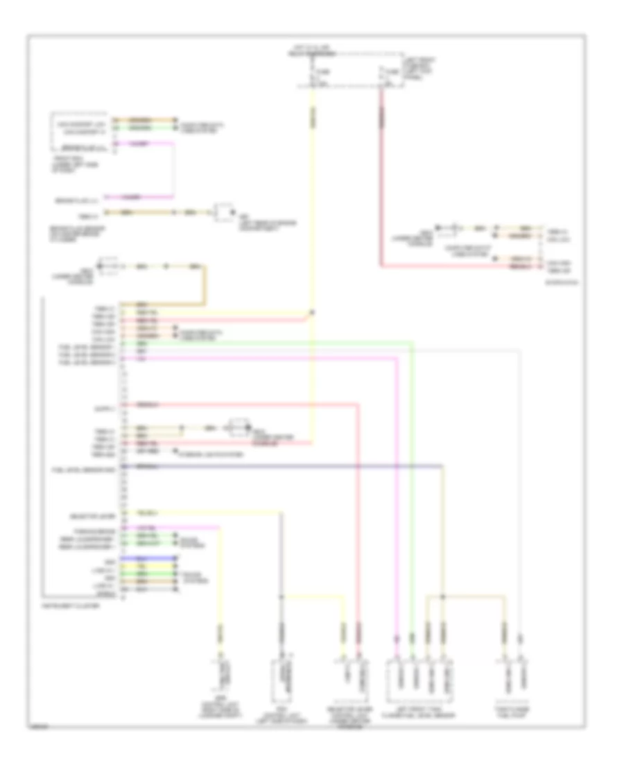
AIR CONDITIONING
Automatic A/C Wiring Diagram, Except Hybrid (1 of 4) for Porsche Panamera 4 2013
List of elements for Automatic A/C Wiring Diagram, Except Hybrid (1 of 4) for Porsche Panamera 4 2013:
- +5v
- 58d
- 5v + air vent
- A/c compressor valve
- A/c control unit
- Analog 1
- Analog 2
- Analog 3
- Analog sig
- Blower temp 3
- Blower temp 6
- Blower temp1 (left side)
- Blower temp2
- Blower temp3 (right side)
- Blower temp4
- Can hi
- Can lo
- Close
- Computer data lines system
- Cooling water shutoff valve
- Front evaporator temp
- Fuse 10a
- Fuse 30a
- Fuse 40a
- Fuse 5a
- Gnd
- Ground
- Hazard warning
- Hazard warning light sw
- Hot at all times
- Hot w/
- Hot w/ kl15 relay energized
- Hot w/ kl30 f relay energized
- Intake temperature
- Interior lights system
- Kl 15 relay energized
- Kl 30f relay energized
- Left air vent lighting cockpit center
- Left front fuse box (in left end of dash)
- Left seat heater ctrl
- Left seat ventilation
- Left temp sens seat
- Lin 1
- Lin 2
- Lin vehicle
- Mb14 (left center of cockpit cross member)
- Mb19 (under center console)
- Mb9 (left "a" pillar)
- Out side temp
- Outside temperature sensor
- Passenger compartment temperature sensor
- Positive
- Pressure sensor
- Pwm
- Red
- Refrigerant pressure sensor
- Rh sens seat temp
- Right air vent lighting cockpit center
- Right front fuse box (in right end of dash)
- Right seat heater ctrl
- Right seat ventilation
- Seats system
- Servo mtrs 1
- Shutoff valve
- Sig
- Sig gnd
- Sig ground
- Signal ground
- Stepper ground
- Term 15
- Term 30 sply seat heater
- Term 30f
- Term 31
- Water val activation close
- Water val activation open
- X010
Automatic A/C Wiring Diagram, Except Hybrid (2 of 4) for Porsche Panamera 4 2013
List of elements for Automatic A/C Wiring Diagram, Except Hybrid (2 of 4) for Porsche Panamera 4 2013:
- Can hi
- Can low
- Computer data lines system
- Driver fan blower regulator
- Electric a/c compressor
- Evaporator temperature sensor
- Front bcm (under left side of dash)
- Ground
- Haz button
- Intake air sensor
- Left blower sensor (on front hvac unit)
- Left footwell sensor
- Left front temperature valve servo motor
- Left rear footwell/ vent servo motor
- Left rear soft shutoff servo motor
- Left rear temperature valve servo motor
- Left side vent servo motor
- Left vent blower sensor (on front hvac unit)
- Lin input
- Lin output
- Lin sig
- Mb03
- Mb11 (right "a" pillar)
- Nca
- Positive
- Red
- Right blower sensor (on front hvac unit)
- Right footwell sensor
- Right rear footwell/ vent servo motor
- Right rear soft shutoff servo motor
- Right vent blower sensor (on front hvac unit)
- Sig
- Signal
- Term 15
- Term 30f
- Term 31
- Warning lt
- X650
Automatic A/C Wiring Diagram, Except Hybrid (3 of 4) for Porsche Panamera 4 2013
List of elements for Automatic A/C Wiring Diagram, Except Hybrid (3 of 4) for Porsche Panamera 4 2013:
- A/c control unit
- Air quality sensor
- Batt sens
- Battery evaporator
- Bypass servo motor
- Defrost flap servo motor
- Extended vent element servo motor
- Fresh air fan motor
- Front evaporator shutoff valve
- Ground
- Left center vent servo motor
- Left footwell servo motor
- Left seat heater
- Lin
- Lin input
- Lin output
- Lr seat occupancy
- Lr seat temp sens
- Mb03
- Mb14 (left center of cockpit cross member)
- Mb19 (under center console)
- Nca
- Positive
- Rear a/c operating unit
- Red
- Right center vent servo motor
- Right footwell servo motor
- Right front temperature valve servo motor
- Right rear temperature valve servo motor
- Right seat heater
- Right side vent servo motor
- Rr seat occupancy
- Rr seat temp sens
- Seats system
- Sig
- Signal
- Temperature sensor
- Term 15
- Term 30
- Term 30f
- Term 31
- Valve open
Automatic A/C Wiring Diagram, Except Hybrid (4 of 4) for Porsche Panamera 4 2013
List of elements for Automatic A/C Wiring Diagram, Except Hybrid (4 of 4) for Porsche Panamera 4 2013:
- (left rear of luggage compt)
- (right rear of engine compt) mb08
- (right rear of luggage compt)
- A/c compressor valve bypass compressor
- Air conditioning relay
- Battery cooling valve
- Bypass throttle +
- Bypass throttle -
- Can high
- Can low
- Computer data lines system
- Coolant return temperature sensor
- Coolant temp 1
- Coolant temp sens
- Coolant temperature sensor
- Dc mtr +
- Dc mtr -
- Dme control unit (right rear of engine compt)
- Engine compartment temperature sensor
- Engine compt temp
- Engine controls system
- Fan 1 pwm
- Fan 2 pwm
- Fan relay
- Feedback
- Fresh-air/ recirculated air flap servo motor
- Fuse 15a
- Fuse 25a
- Fuse 5a
- Gnd
- Ground
- High volt battery system
- Hot at all times
- Hot w/ terminal 15 relay energized
- Left battery fan
- Left front fuse box (left kick panel)
- Lin
- Lin input
- Lin output
- Mb18
- Mb26
- Mb27
- Mb27 (left rear of luggage compt)
- Positive
- Pwm
- Ram air flap servo motor
- Rear fuse box (row c)
- Red
- Right battery fan
- Sens gnd
- Sensor +
- Sensor -
- Sensor sig
- Sply 5v
- Sun sensor
- Term 15
- Term 30
- Term 31
- Valve open
- X031
- X035
- X902
Automatic A/C Wiring Diagram, Hybrid (1 of 4) for Porsche Panamera 4 2013
List of elements for Automatic A/C Wiring Diagram, Hybrid (1 of 4) for Porsche Panamera 4 2013:
- +5v
- 58d
- A/c control unit
- Analog 1
- Analog 2
- Analog 3
- Analog sig
- Blower temp 3
- Blower temp 6
- Blower temp1 (left side)
- Blower temp2
- Blower temp3 (right side)
- Blower temp4
- Can hi
- Can lo
- Close
- Computer data lines system
- Cooling water shutoff valve
- Front evaporator temp
- Fuse 10a
- Fuse 30a
- Fuse 40a
- Fuse 5a
- Gnd
- Ground
- Ground servo motors
- Hazard warning
- Hazard warning light sw
- Hot at all times
- Intake temperature
- Interior lights system
- Left air vent lighting cockpit center
- Left front fuse box (left kick panel)
- Left seat heater ctrl
- Left seat ventilation
- Left temp sens seat
- Lin 1
- Lin 2
- Lin vehicle
- Mb14 (left side of support frame)
- Mb19 (under center console)
- Mb9 (left "a" pillar)
- Out side temp
- Passenger compartment temperature sensor
- Positive
- Pressure sensor
- Pwm
- Red
- Refrigerant pressure sensor
- Rh sens seat temp
- Right air vent lighting cockpit center
- Right front fuse box (right kick panel)
- Right seat heater ctrl
- Right seat ventilation
- Seats system
- Servo mtrs 1
- Sig
- Sig gnd
- Sig ground
- Signal ground
- Temperature outside sensor
- Term 15
- Term 30 sply seat heater
- Term 30f
- Term 31
- Water pump rly
- Water val activation close
- Water val activation open
- X010
Automatic A/C Wiring Diagram, Hybrid (2 of 4) for Porsche Panamera 4 2013
List of elements for Automatic A/C Wiring Diagram, Hybrid (2 of 4) for Porsche Panamera 4 2013:
- After run coolant pump
- Driver fan blower regulator
- Evaporator temperature sensor
- Front bcm (under left side of dash)
- Ground
- Intake air temperature sensor
- Led function
- Left footwell blower sensor
- Left front temperature valve servo motor
- Left rear fan outlet sensor (on front hvac unit)
- Left rear footwell/ vent servo motor
- Left rear soft shutoff servo motor
- Left rear temperature valve servo motor
- Left side vent servo motor
- Left vent blower sensor (on front hvac unit)
- Lin input
- Lin output
- Lin sig
- Mb11 (right "a" pillar)
- Mb7 (left rear of engine compt)
- Positive
- Red
- Right footwell blower sensor
- Right rear fan outlet sensor (on front hvac unit)
- Right rear footwell/ vent servo motor
- Right rear soft shutoff servo motor
- Right vent blower sensor (on front hvac unit)
- Sig
- Signal
- Term 30f
- Term 31
- Warning lt
- Water circulating pump relay
Automatic A/C Wiring Diagram, Hybrid (3 of 4) for Porsche Panamera 4 2013
List of elements for Automatic A/C Wiring Diagram, Hybrid (3 of 4) for Porsche Panamera 4 2013:
- A/c control unit
- Air quality sensor
- Bypass servo motor
- Defrost flap servo motor
- Extended vent element servo motor
- Fresh air fan
- Gnd
- Ground
- Left center vent servo motor
- Left footwell servo motor
- Left seat heater
- Lin
- Lin input
- Lin output
- Lr seat occupancy
- Lr seat temp sens
- Mb14 (left center of cockpit cross member)
- Mb19 (under center console)
- Positive
- Rear a/c operating unit
- Red
- Right center vent servo motor
- Right footwell servo motor
- Right front temperature servo motor
- Right rear valve temperature servo motor
- Right seat heater
- Right side vent servo motor
- Rr seat occupancy
- Rr seat temp sens
- Seats system
- Signal
- Term 15
- Term 30
- Term 30f
- Term 31
Automatic A/C Wiring Diagram, Hybrid (4 of 4) for Porsche Panamera 4 2013
List of elements for Automatic A/C Wiring Diagram, Hybrid (4 of 4) for Porsche Panamera 4 2013:
- 3.6l & 4.8l
- 4.8l twin turbo
- Can high 1
- Can low 1
- Computer data lines system
- Cooling water
- Cooling water fan (3.6l & 4.8l)
- Cooling water fan (4.8l twin turbo)
- Ctrl 1
- Dme control unit (right rear of engine compt)
- Engine compartment temperature sensor
- Engine compt temp
- Engine controls system
- Engine sensor
- Fresh-air/ recirculated air flap servo motor
- Fuse 5a
- Fuse 80a
- Gnd
- Ground
- Hot at all times
- Hot w/ dme1 relay energized
- Left front fuse box (left kick panel)
- Lin
- Lin input
- Lin output
- Mb18 (under center console)
- Mb3
- Mid fuse box
- Positive
- Pwm
- Ram air flap servo motor
- Red
- Sig
- Sun sensor
- Term 15
- Term 30
- Term 31
- Term 87
ANTI-LOCK BRAKES
Anti-lock Brakes Wiring Diagram for Porsche Panamera 4 2013
List of elements for Anti-lock Brakes Wiring Diagram for Porsche Panamera 4 2013:
- Brake pad wear
- Brk sig
- Can high
- Can low
- Computer data lines system
- Fr wheel sensor
- Front bcm (under left side of dash)
- Fuse 10a
- Fuse 25a
- Fuse 40a
- Fuse 5a
- Gnd
- Hot at all times
- Hot w/ kl 15a relay energized
- Left front brake pad sensor
- Left front fuse box (left kick panel)
- Left front wheel sensor (on left front wheel hub assembly)
- Left rear brake pad sensor
- Left rear wheel sensor (on left rear wheel hub assembly)
- Lf wheel sensor
- Lr wheel sensor
- Mb06 (right rear of engine compt)
- Mb14 (left side of support frame)
- Mb26 (right rear of luggage compt)
- Porsche stability management (psm) control unit (right side of engine compt)
- Rear bcm (left side of luggage compt)
- Red
- Rf wheel sensor
- Right front brake pad sensor
- Right front fuse box (right kick panel)
- Right front wheel sensor (on right front wheel hub assembly)
- Right rear brake pad sensor
- Right rear wheel sensor (on right rear wheel hub assembly)
- Rl speed sensor out
- Rl wheel sensor
- Rr speed sensor out
- Rr wheel sensor
- Rr wheel spd sens
- Sensor cluster (under front of floor console)
- Stop light
- Stop light out
- Stop light sw
- Stop light sw gnd
- Stop light switch (top of brake pedal assembly)
- Terminal 15
- Terminal 30
- Terminal 30tp
- Terminal 31
- Ubatt
- Ubatt bls
- Wake up epb
- Wake up psm
- Wheel spd sens 1
- X410
- X420
- X430
- X440
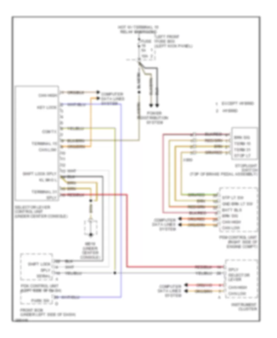
ANTI-THEFT
Anti-theft Wiring Diagram for Porsche Panamera 4 2013
List of elements for Anti-theft Wiring Diagram for Porsche Panamera 4 2013:
- (center of support frame) gp4
- (luggage compt, left of battery) (w/ alarm siren) alarm horn
- (under driver's seat) gp7
- (under front passenger's seat) gp6
- Air conditioning system
- Alarm horn
- Alarm siren
- Alarm siren (luggage compt, left of battery)
- Antenna alarm
- Antenna alarm shield
- Can comfort high
- Can comfort low
- Can drive high
- Can drive low
- Clock immobilizer
- Computer data lines system
- Current distributor (behind right side of dash)
- Data
- Data immobilizer
- Data line data
- Datas line clock
- Electronic ignition lock
- Emergency power pin
- Exterior lights system
- External ind
- Fuse f2 7.5a
- Fuse f3 15a
- Fuse f6 80a
- Fuses holder b
- Fuses holder c
- Fzv off
- Gp3 (left side of support frame)
- Gp4 (center of support frame)
- Gp7 (under driver's seat)
- Ground
- Hot at all times
- Ignition lock sw 1
- Ignition lock sw 2
- Ignition lock sw 3
- Ignition lock sw 4
- Ignition lock sw 5
- Ignition lock sw 6
- Ignition lock sw 7
- Interior sensor
- Interior sensor (coupe: center floor console)
- Left diversity antenna amplifier (left "a" pillar)
- Nca
- Pas control unit (behind left side of dash)
- Power distribution system
- Rear control unit (under rear of center console)
- Red
- Reg enable
- Selector lever sw/lock
- Serial data
- Serial data transfer
- Shield
- Signal ground
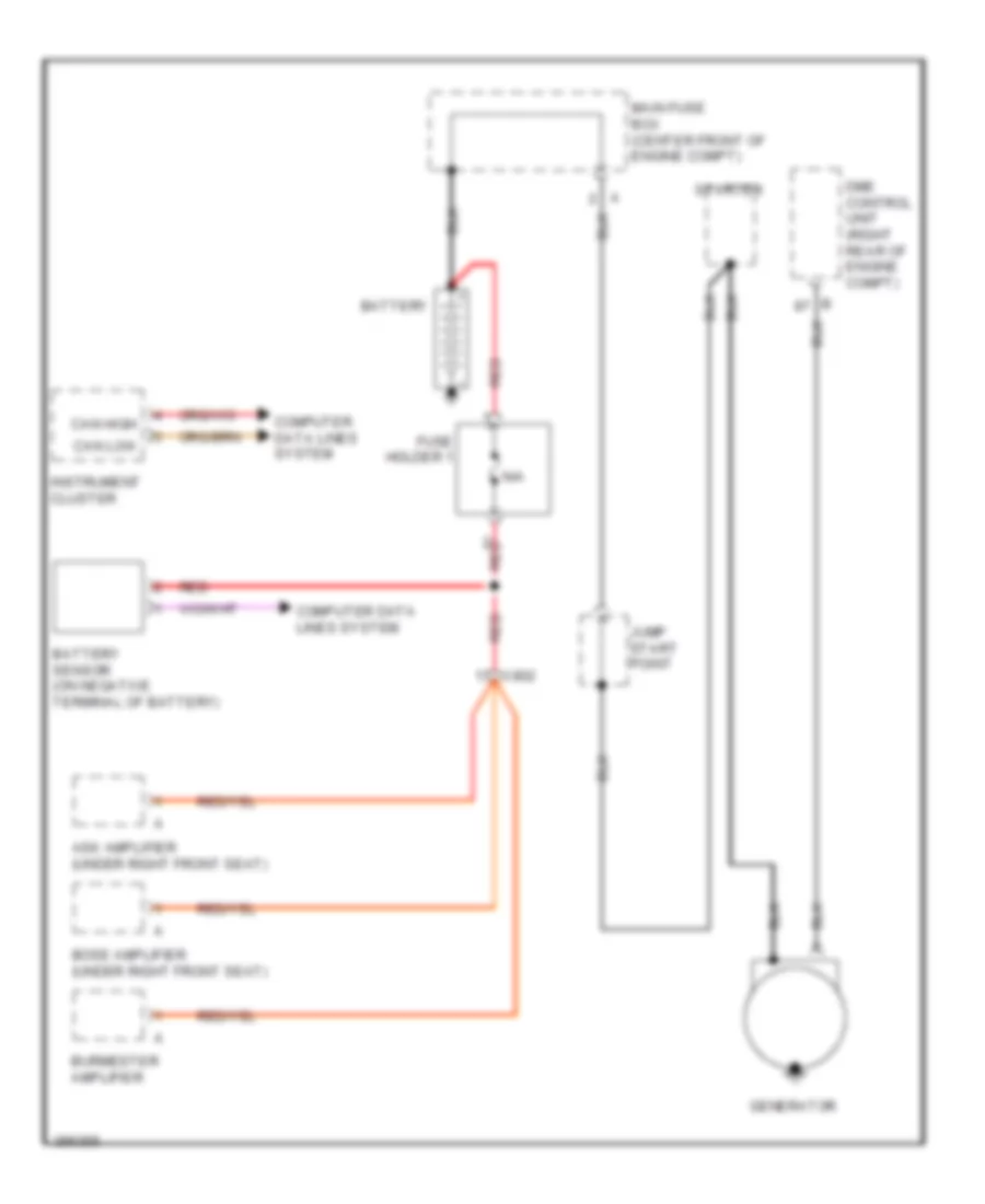
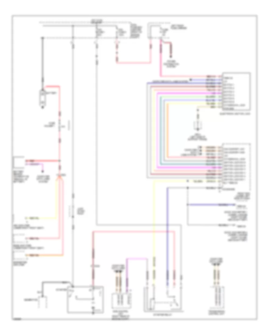
- Starting/charging system
- Steering col +
- Steering col -
- Steering wheel lock (steering column)
- Stop light sw
- Switch 1
- Switch 2
- Switch 3
- Switch 4
- Switch 5
- Switch 6
- Switch 7
- Term 15 act low
- Term 15 diag
- Term 15 start
- Term 30
- Term 31
- Term 31 1
- Term 31 2
- Term 50 act high
- Term 50 diag
- Term 75 act low
- Term 86s act low
- Terminal 15 relay (relay support 1)
- Tilt sensor
- Tilt sensor (luggage compt, left of battery)
- Transmissions system
- Voltage 12v
- Voltage control ign lock
- X060
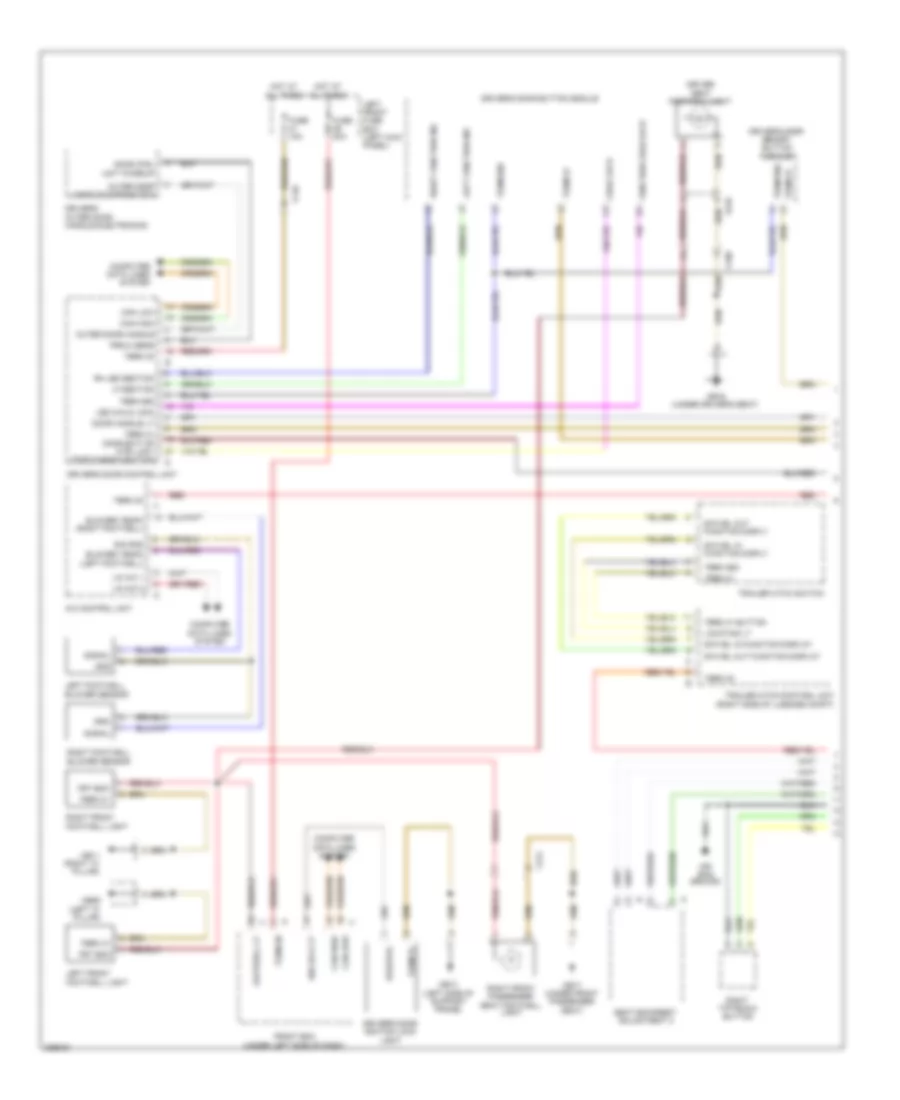
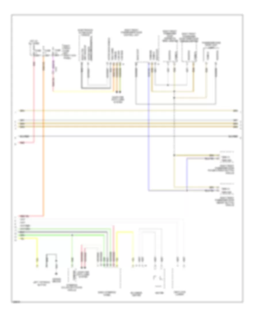
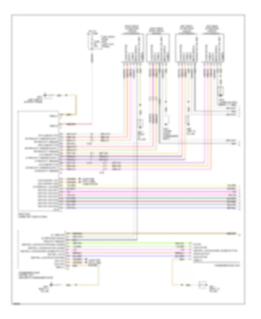
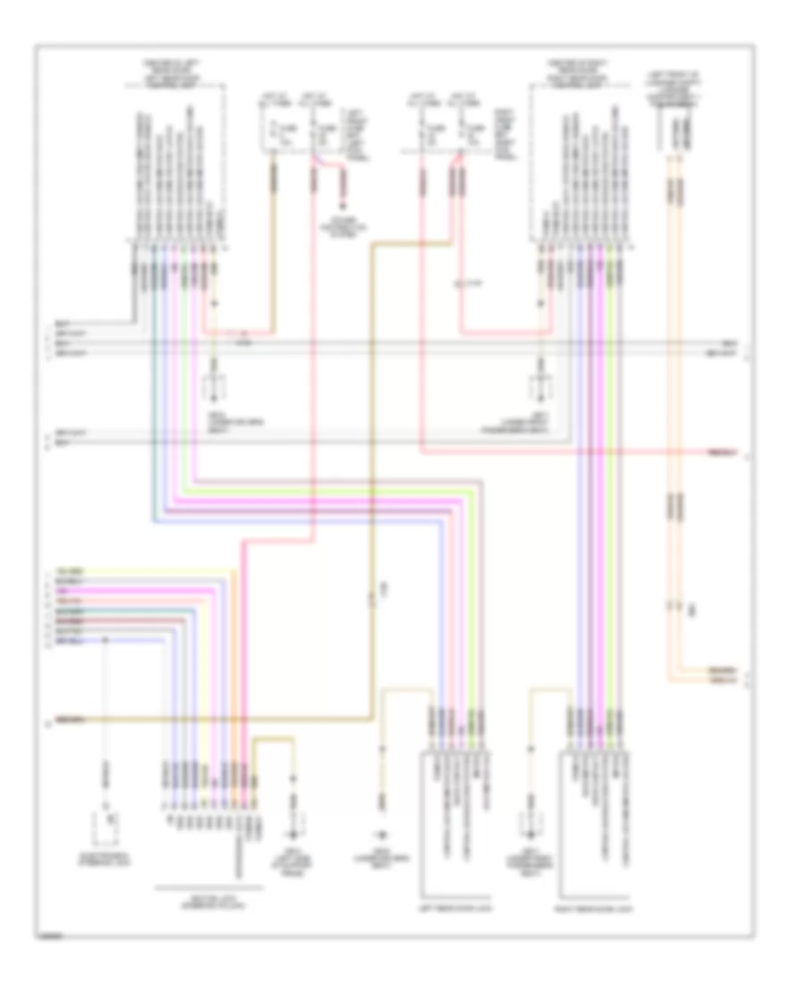
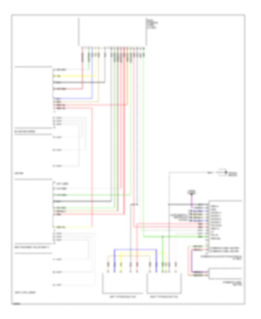
BODY CONTROL MODULES
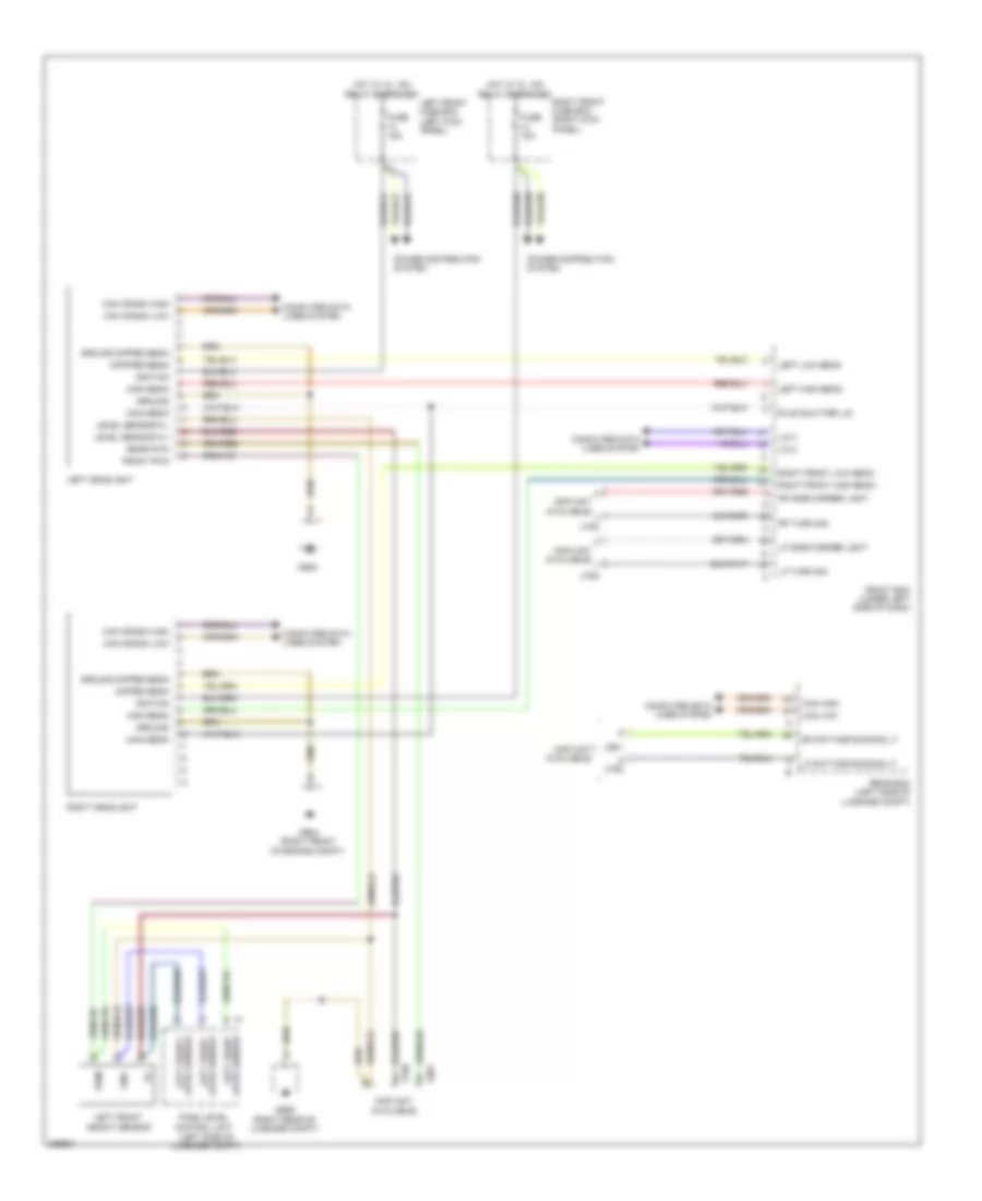
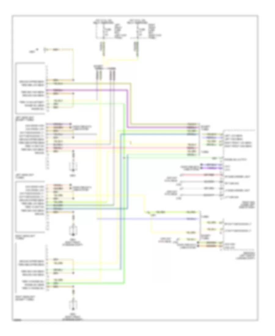
Front Controller Wiring Diagram for Porsche Panamera 4 2013
List of elements for Front Controller Wiring Diagram for Porsche Panamera 4 2013:
- +5v sensor axle heights
- Actuator filler flap close
- Actuator filler flap up
- Air conditioning system
- Antenna bumper control unit
- Antenna in luggage compt 1
- Antenna in pass compt 1
- Antenna in pass compt 2
- Anti-lock brakes system
- Brake fluid level
- Can comfort high
- Can comfort low
- Computer data lines system
- Controlvalve servotronic + (hs)
- Controlvalve servotronic - (ls)
- Crash signal input pwm
- Door locks system
- Electronic power steering system
- Electronic suspension system
- Elv
- Elv sply
- Enable term 15 elv unlocked
- Engine controls system
- Exterior lights system
- Footwell light
- Front bcm (under left side of dash)
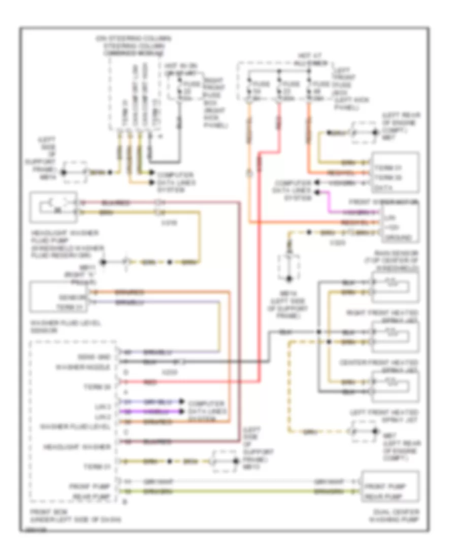
- Front dual washing pump
- Fuse 15a
- Fuse 30a
- Fuse 5a
- Headlight washer
- Headlights system
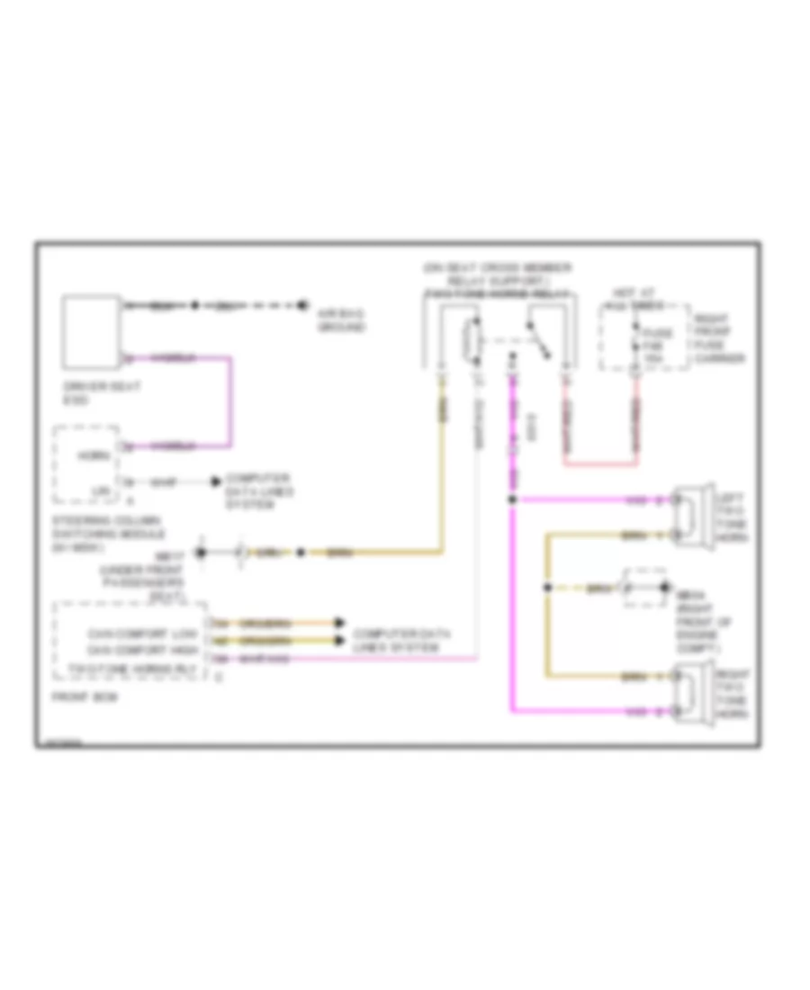
- Horns system
- Hot at all times
- Hot w/ kl 15a relay energised
- Ignition lock light
- Ignition lock sw 2
- Ignition lock sw 5
- Ignition lock sw 6
- Input sensor axle heights
- Instrument cluster system
- Interior lights system
- Kl 15a relay
- Left antenna b-pillar
- Left front fuse box
- Lf button, close
- Lf high beam
- Lf low beam
- Lf side ind
- Lf side marker light
- Lf term 31 proximity sensor
- Lf turn signal
- Light switch position 0
- Lin
- Lin 1
- Lin 2
- Lin 3 comfort low
- Lr button, close
- Lr ind
- Lr term 31 proximity sensor
- Lwr output
- Main fuse box (center front of engine compt)
- Mb13 (left side of support frame)
- Mb14 (left side of support frame)
- Microswitch front lid
- Park switch
- Power distribution system
- Rear bcm (left side of luggage compt)
- Rear dual washing pump
- Rear lid right antenna
- Red
- Relay kl15
- Relay term 50
- Rf button, close
- Rf high beam
- Rf low beam
- Rf side ind
- Rf side marker light
- Rf term 31 proximity sensor
- Rf turn signal
- Right antenna b-pillar
- Rr button, close
- Rr term 31 proximity sensor
- Rr turn signal
- Sensor ground
- Shift interlock system
- Starting/charging system
- Steering column column lock
- Sw 1 ignition lock
- Sw 3 ignition lock
- Sw 4 ignition lock
- Switch cover shutter ri/le
- Term 15
- Term 15 in diagnostics
- Term 15sv
- Term 30
- Term 30 1
- Term 30 2
- Term 30 3
- Term 30 headlight washer
- Term 31
- Term 50 diagnostics
- Trunk, tailgate, fuel doors system
- Two-tone horns, relay
- Uhf antenna shield
- Uhf antenna signal
- Wake up psm
- Warning light button
- Washer fluid level
- Wheel speed sensor 1
- Windscreen washer nozzle
- Wiper/washer system
- Withdrawal lock ezs
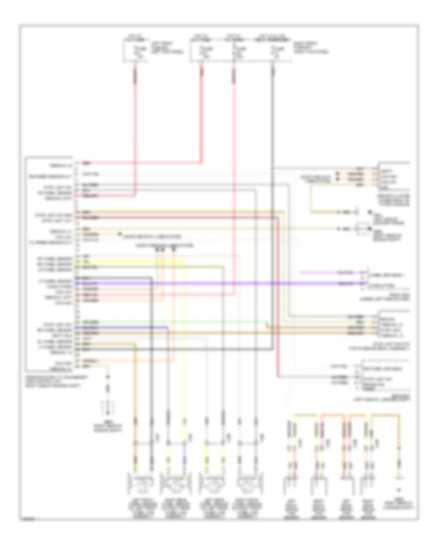
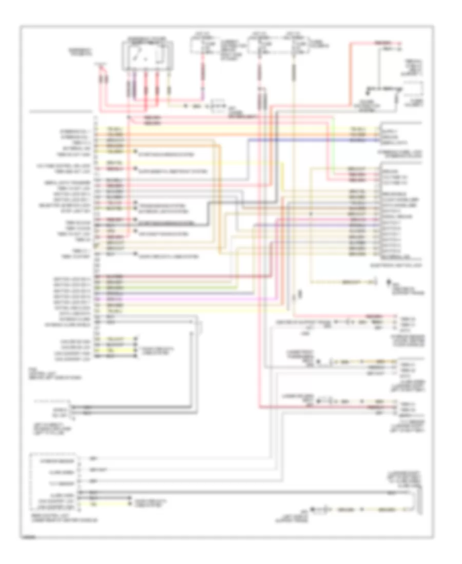
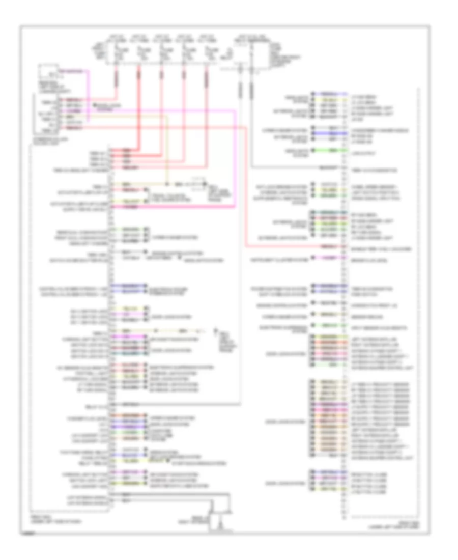
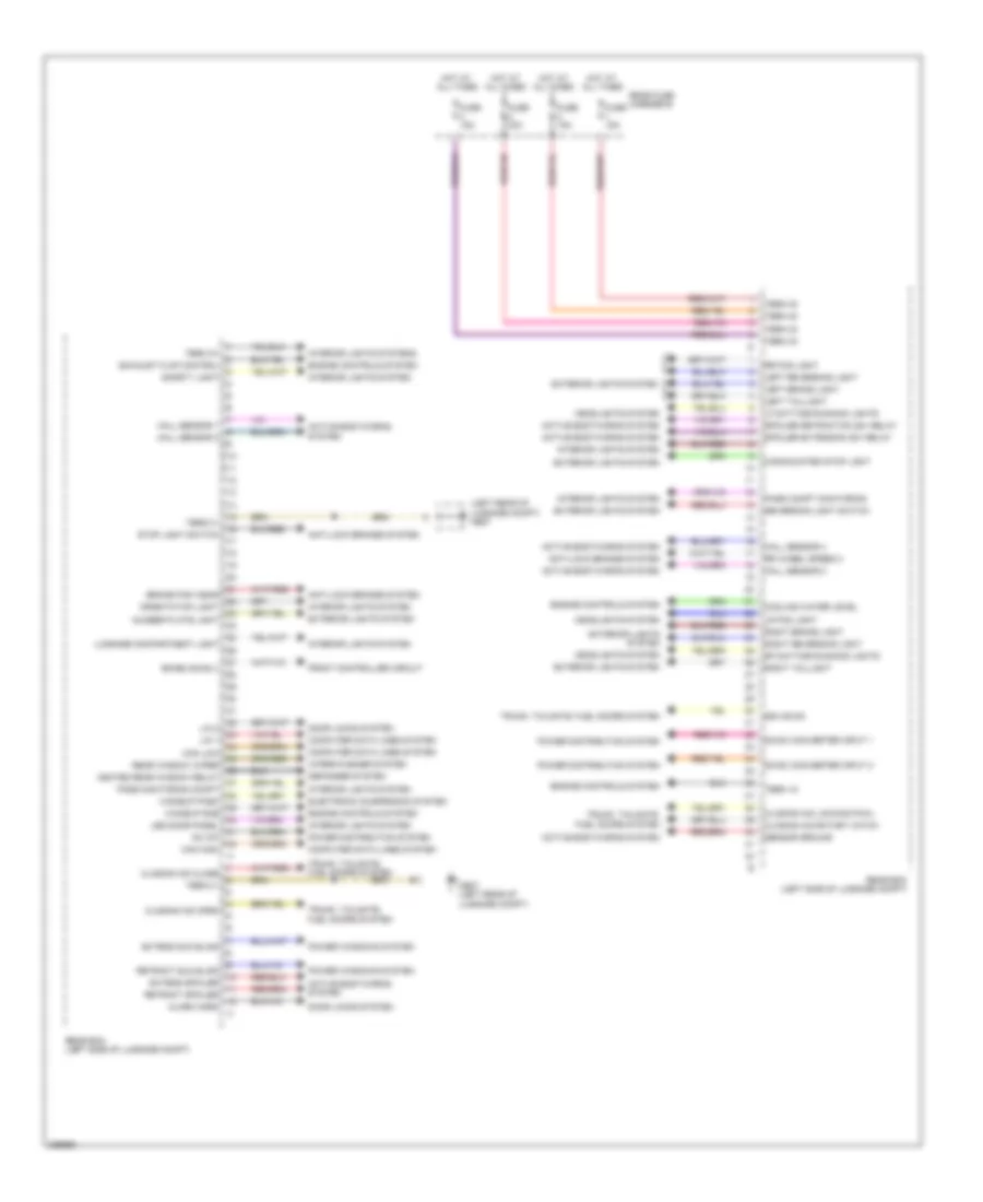
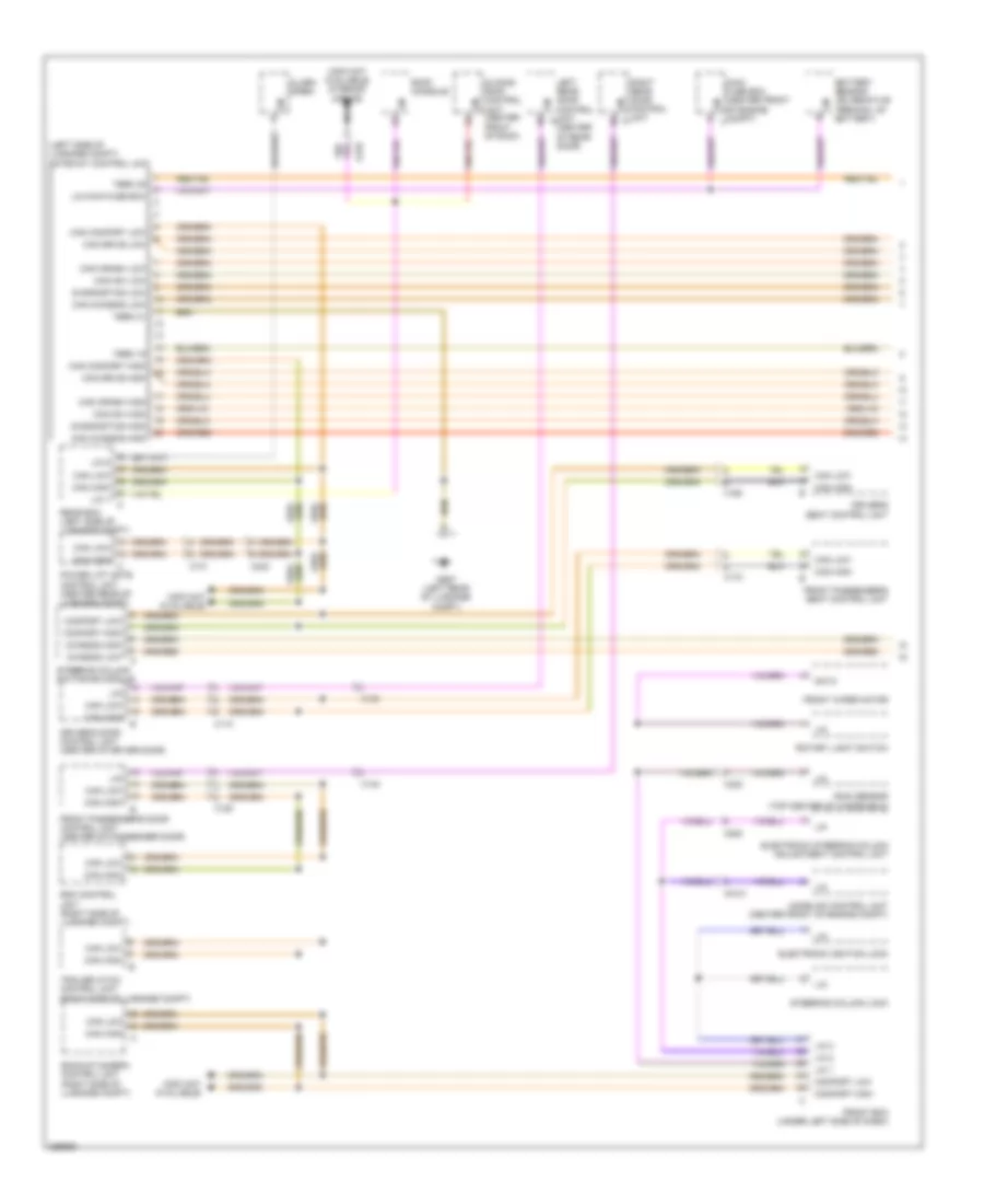
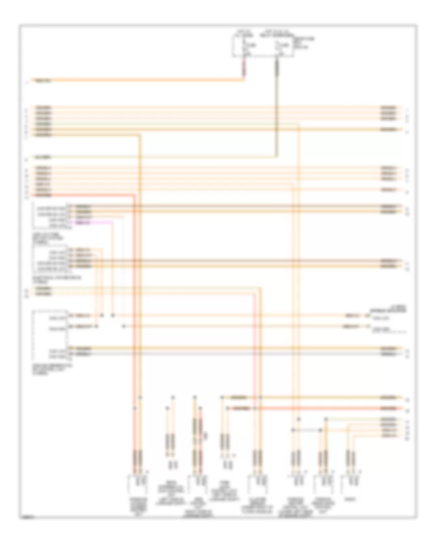
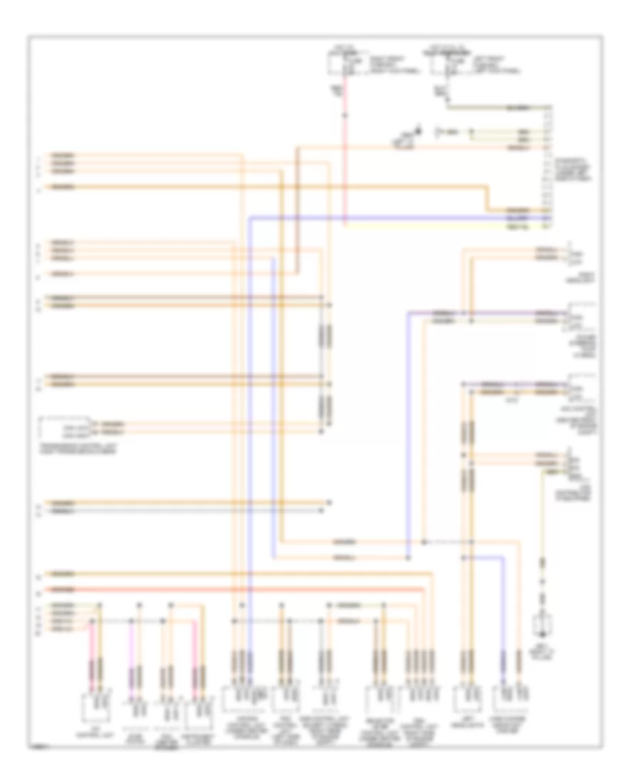
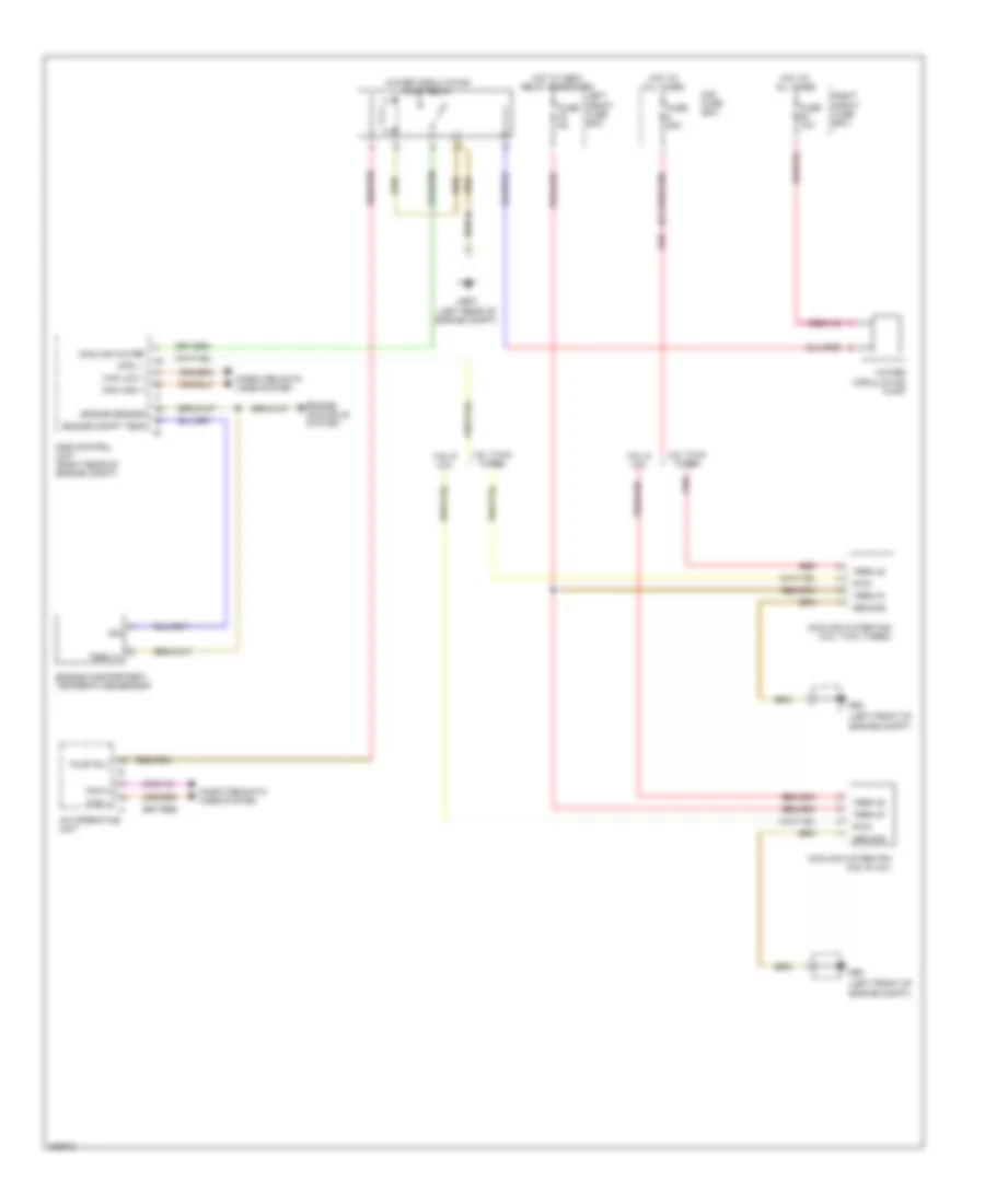
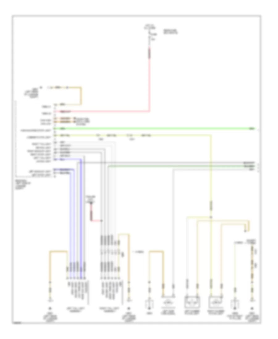
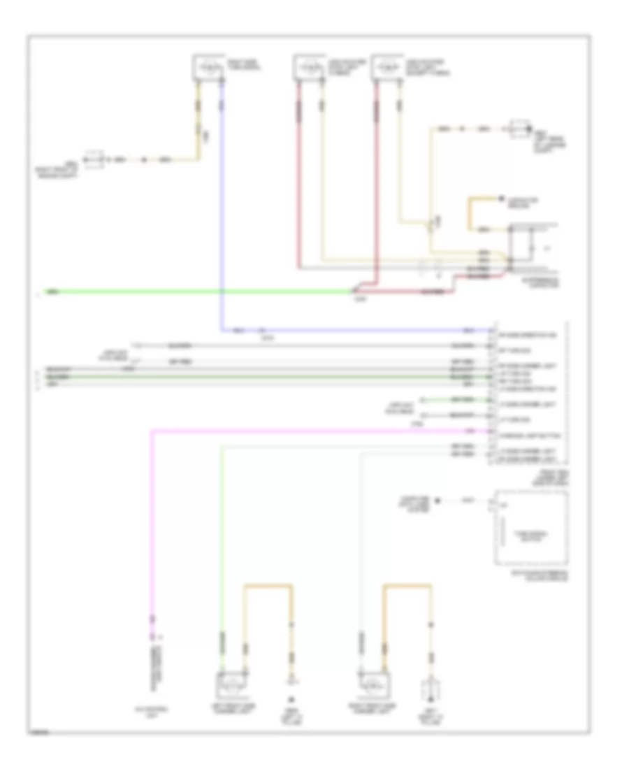
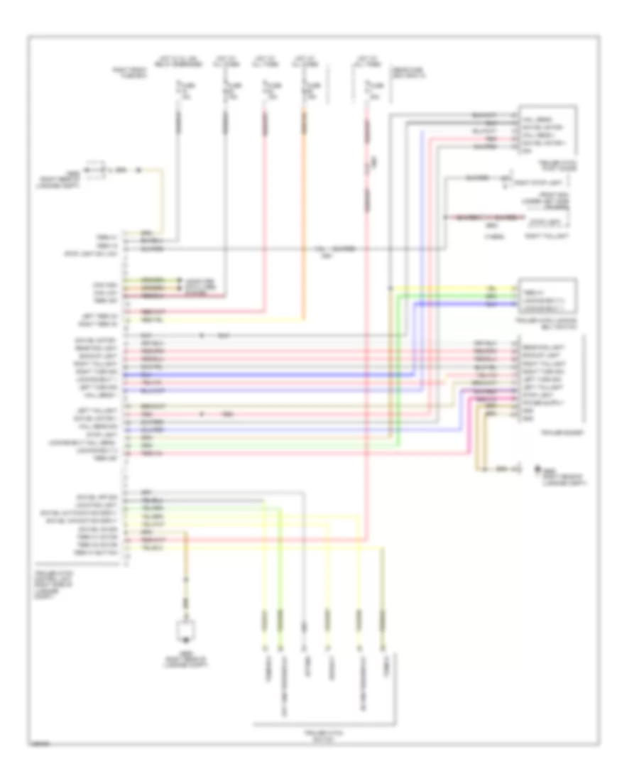
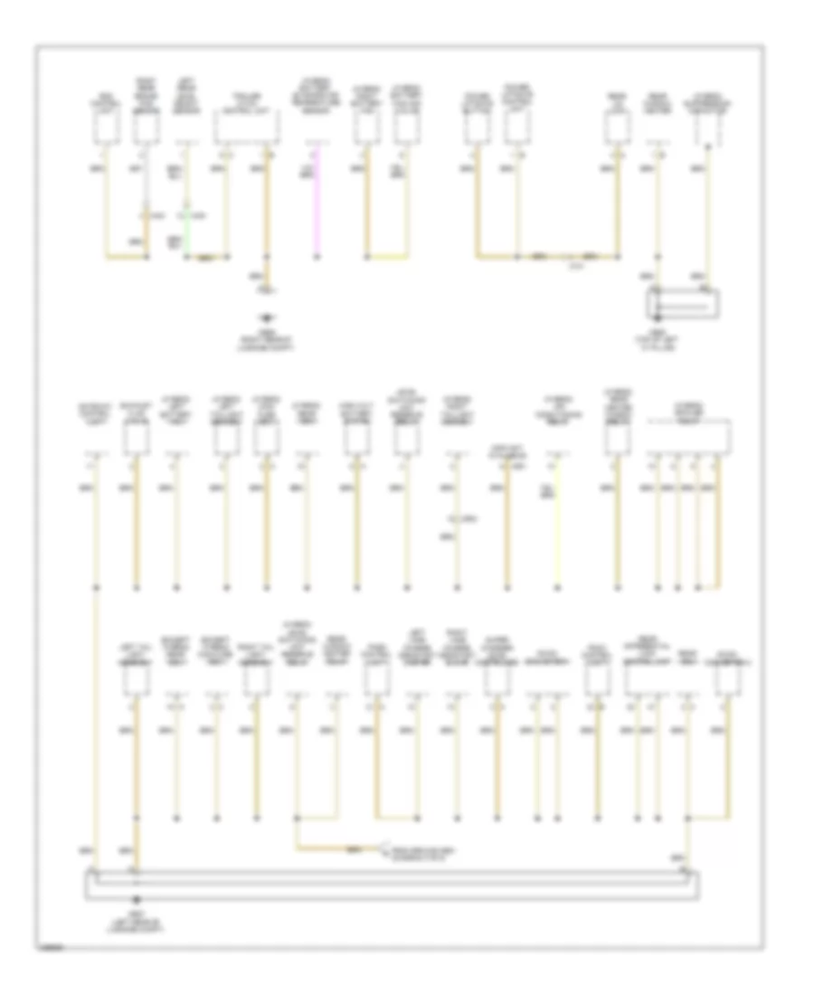
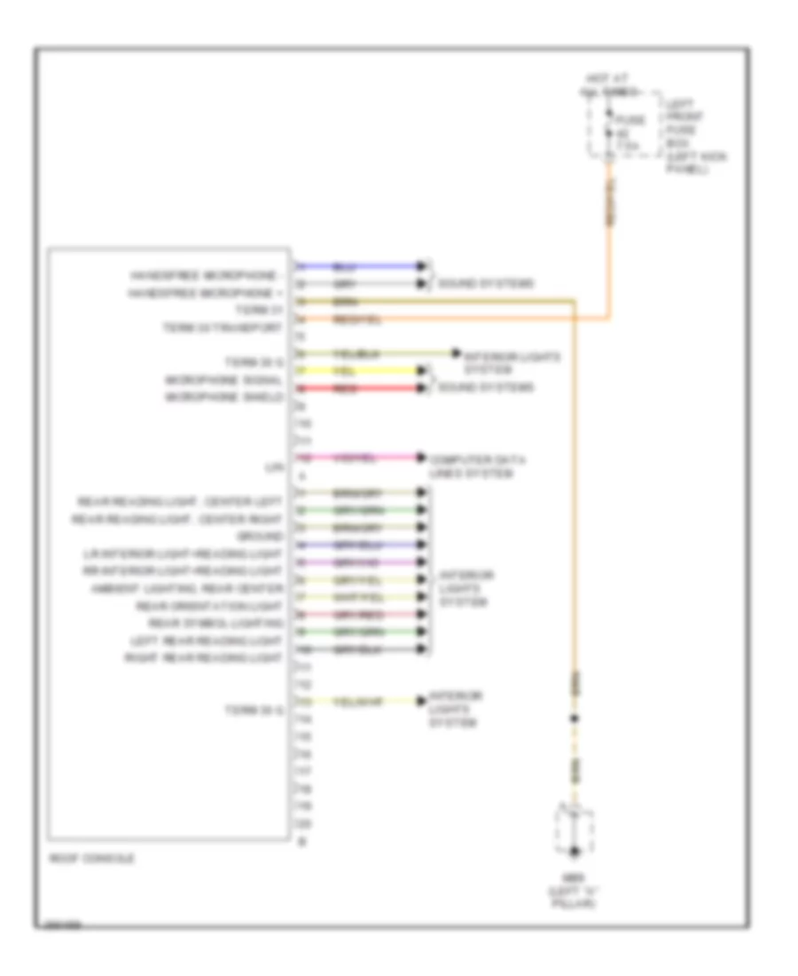
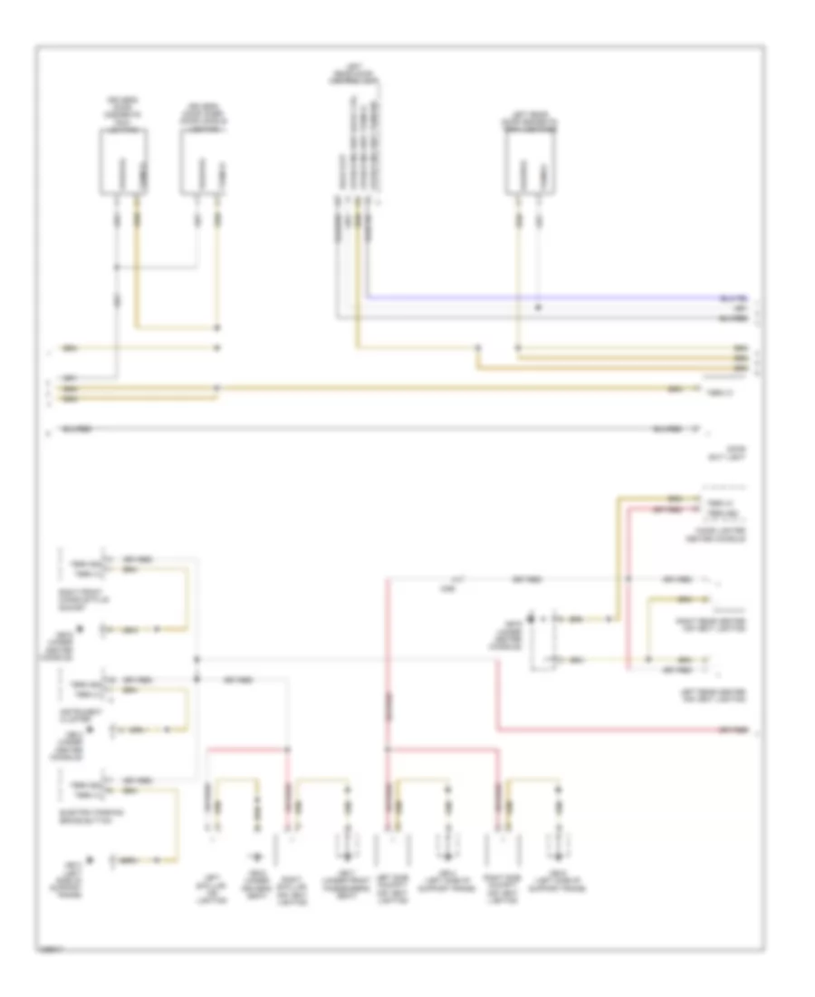
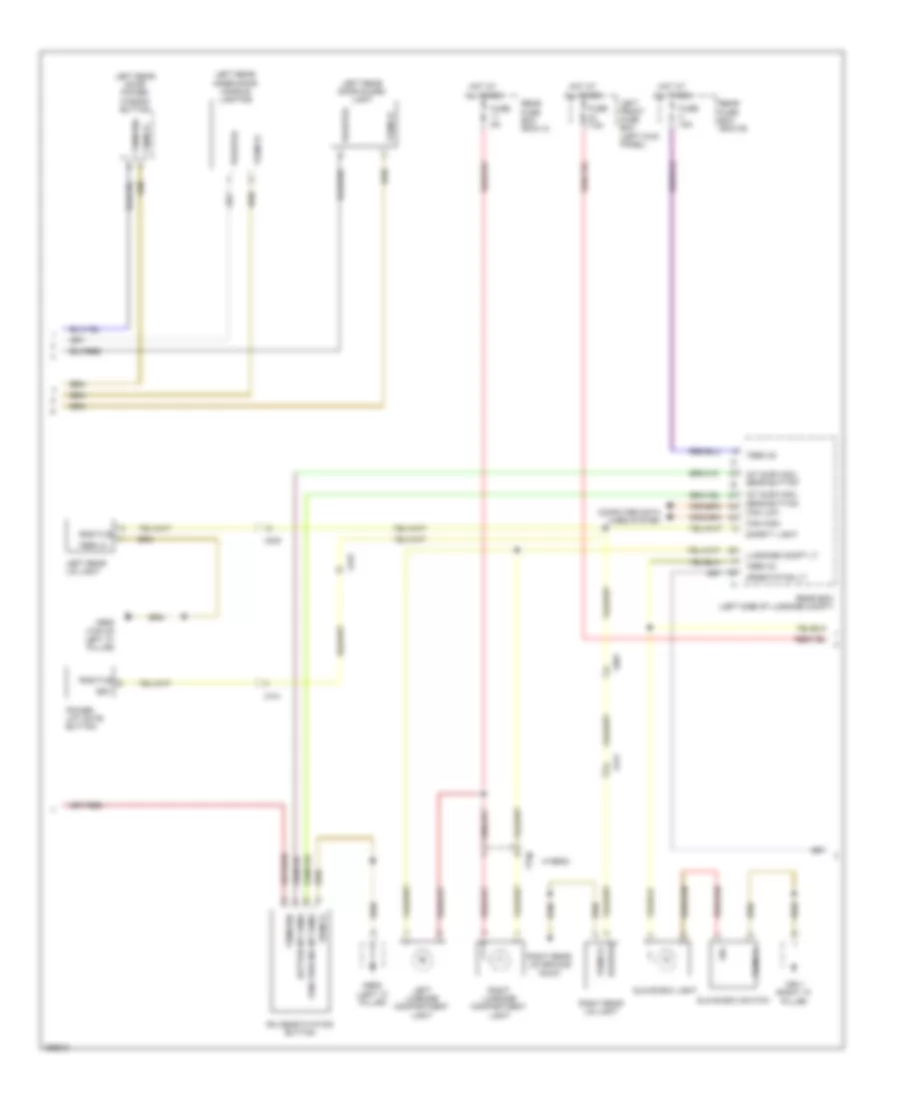
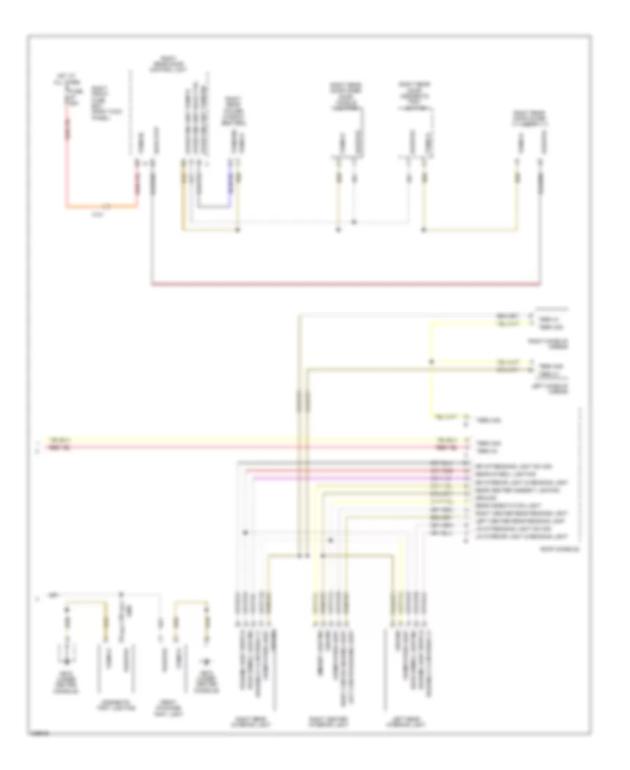
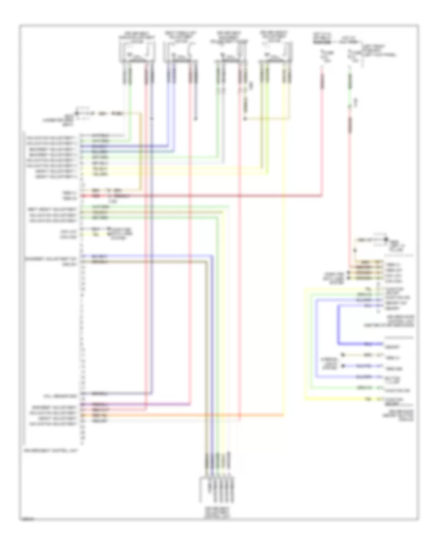
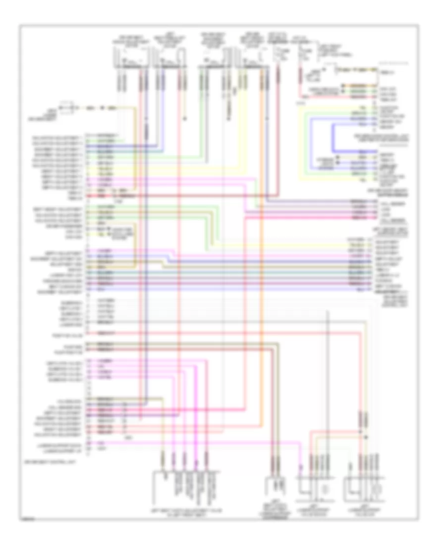
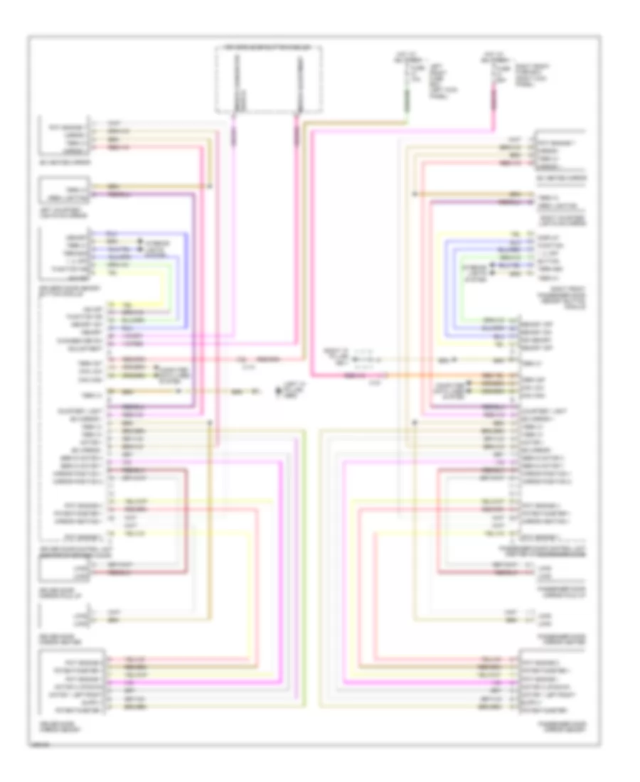
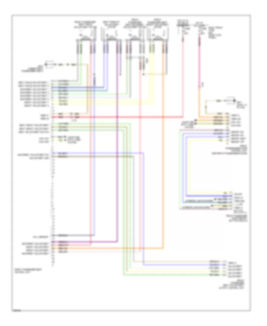
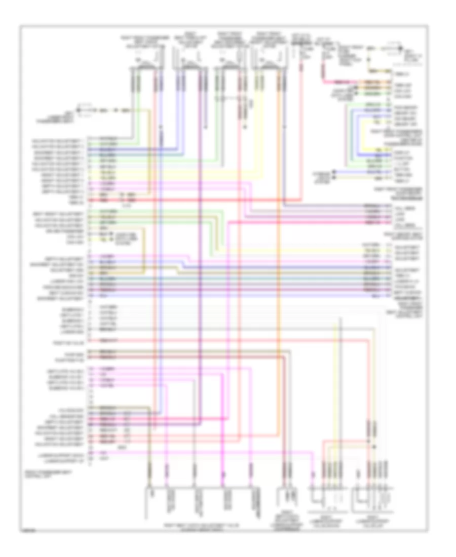
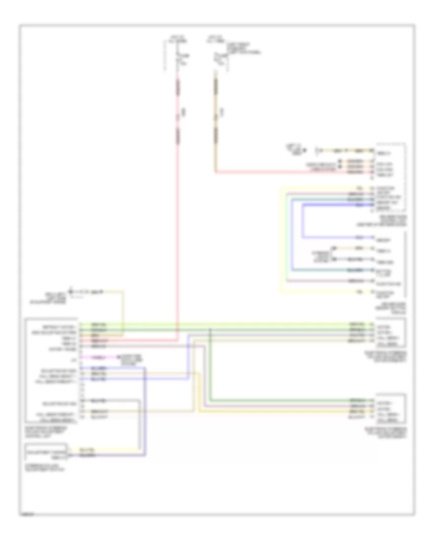
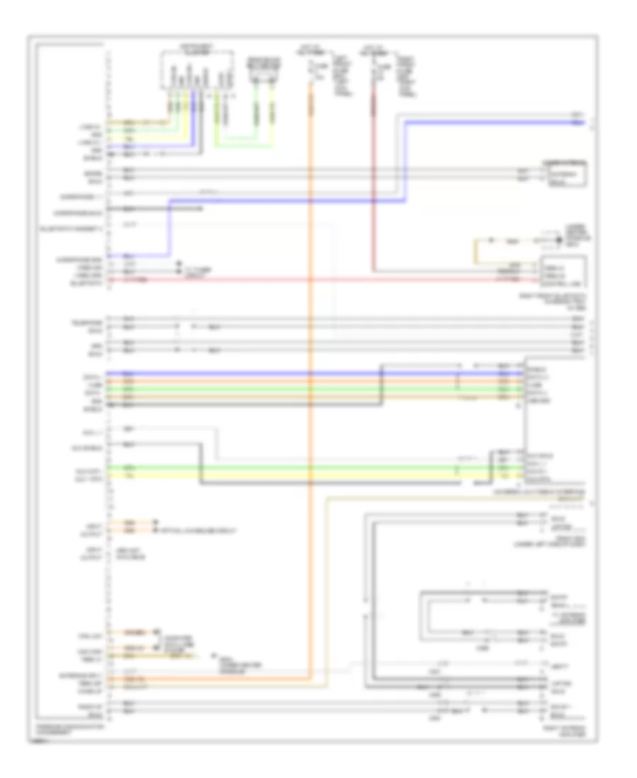
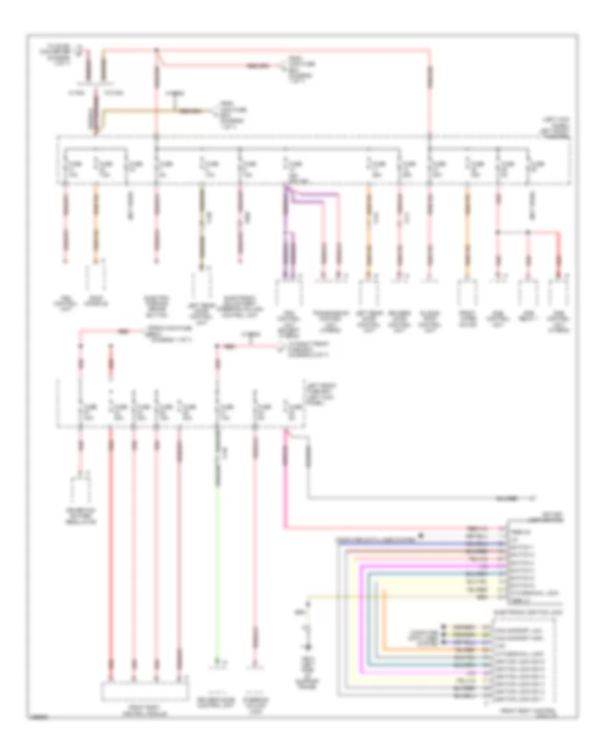
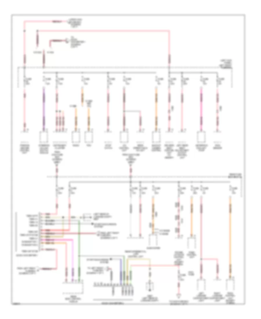
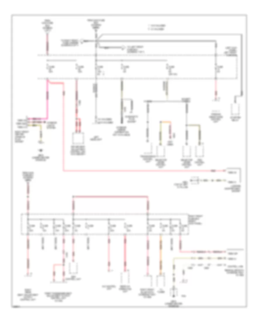
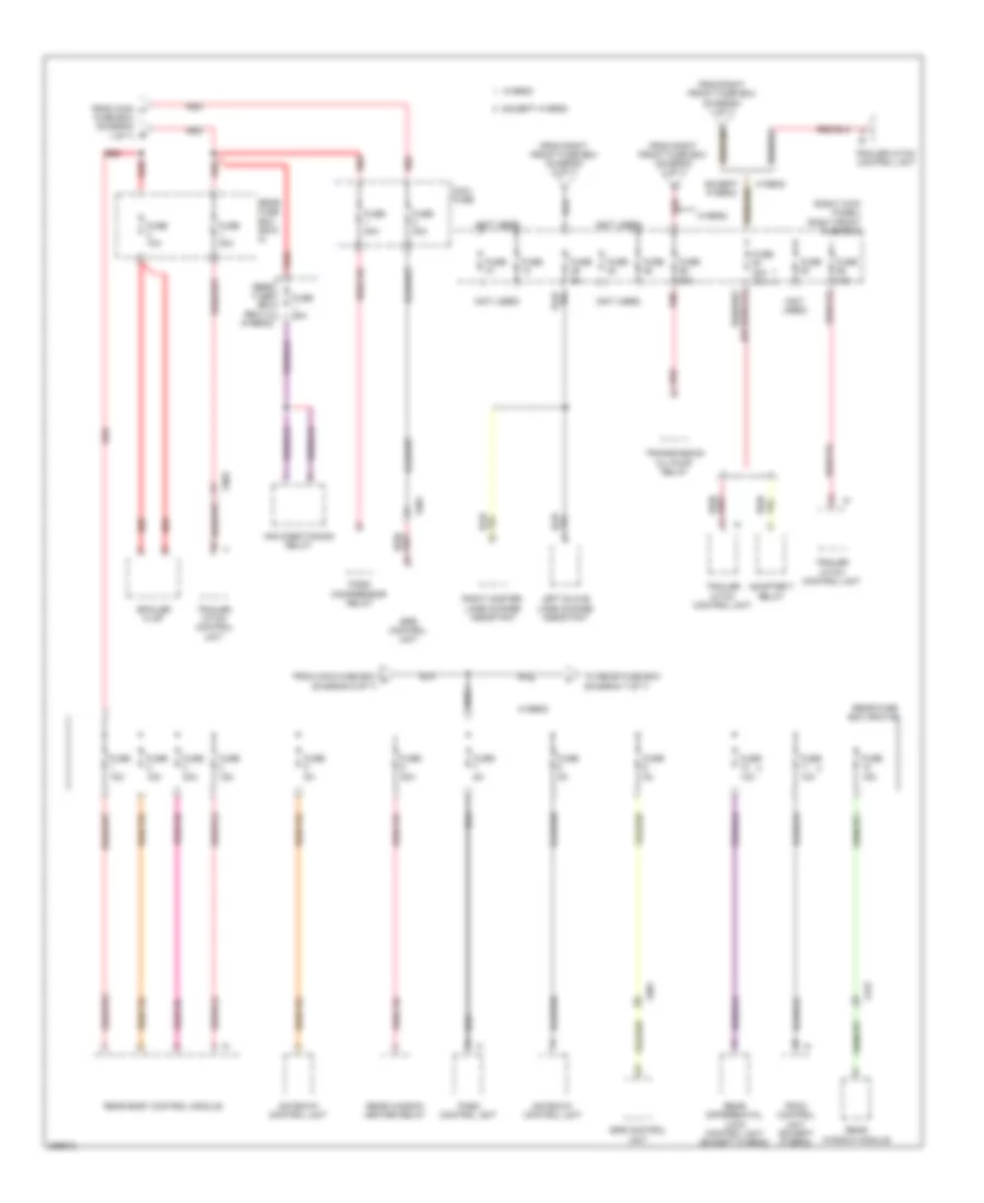
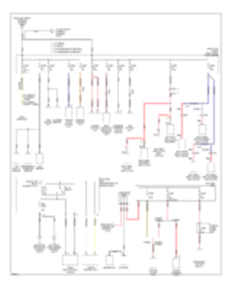
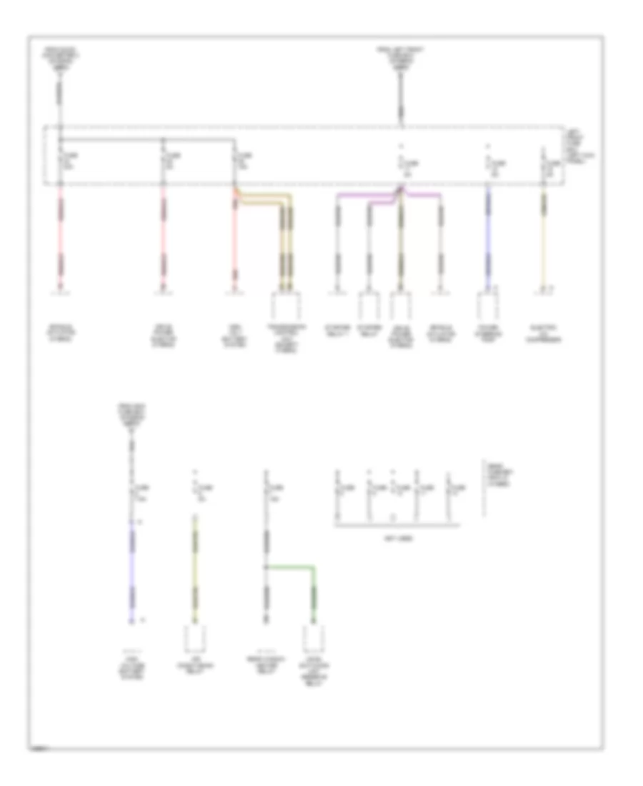
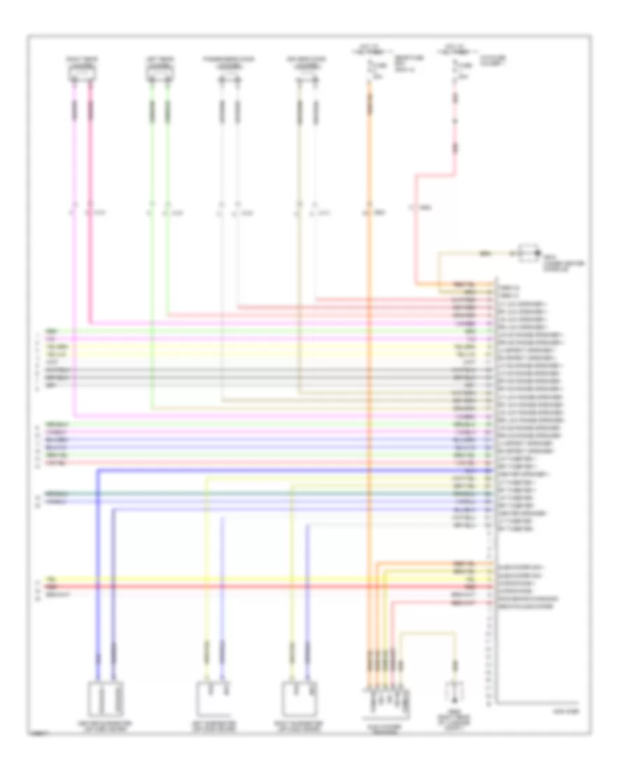
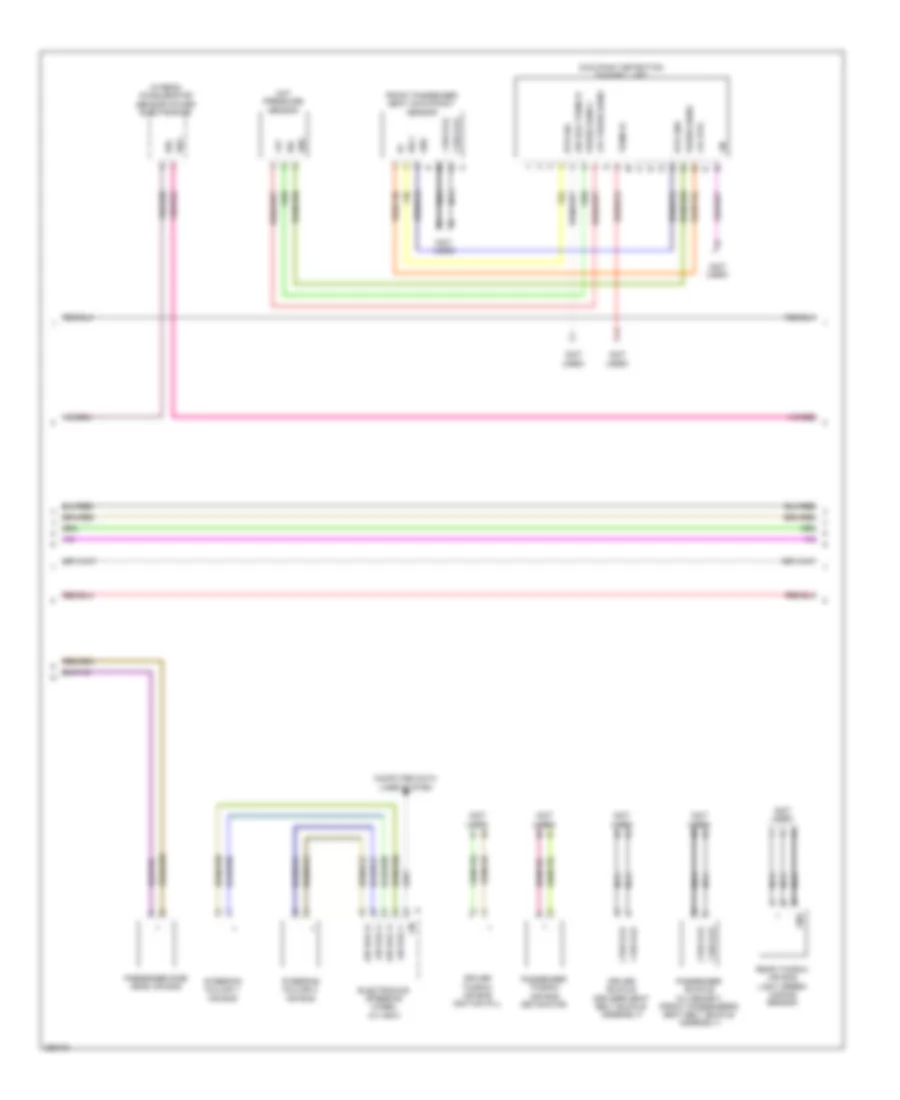
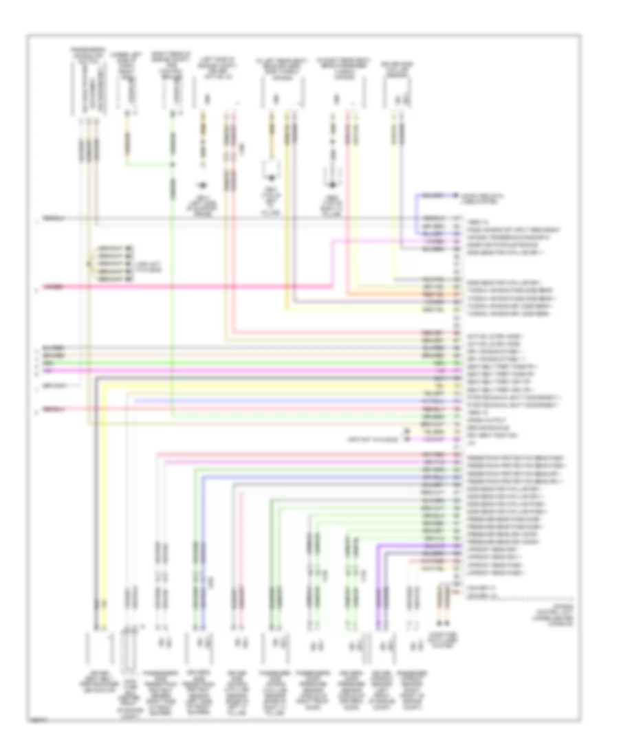
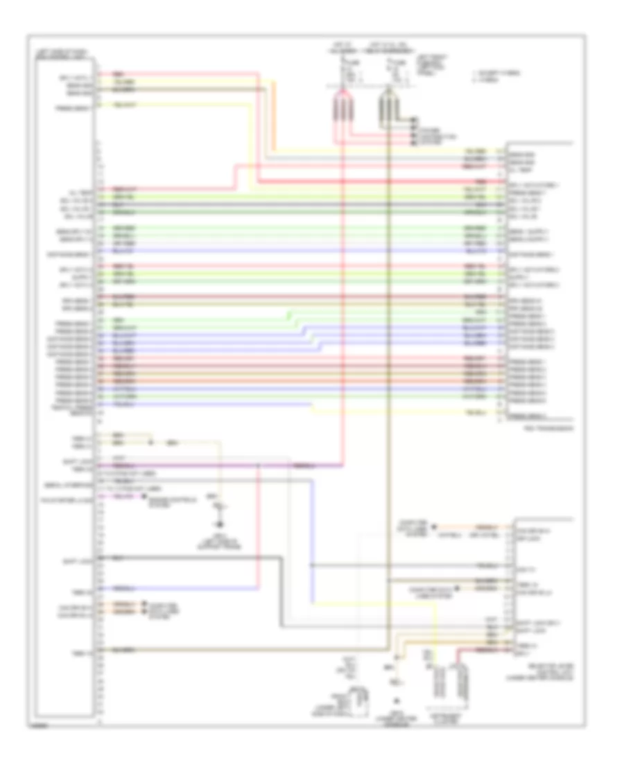
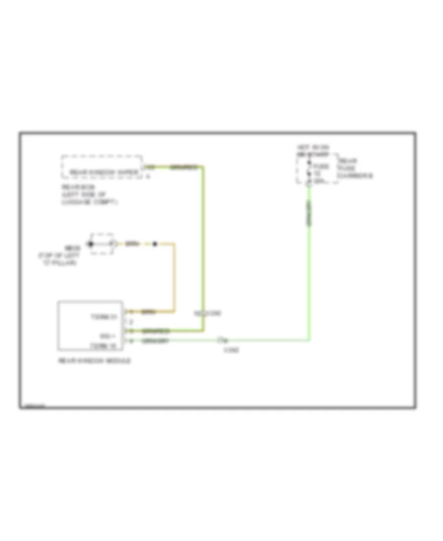
Rear Control Unit Wiring Diagram for Porsche Panamera 4 2013
List of elements for Rear Control Unit Wiring Diagram for Porsche Panamera 4 2013:
- (left rear of luggage compt) mb27
- Active bodyworks system
- Alarm horn
- Anti-lock brakes system
- Brake pad wear
- Can high
- Can low
- Closing aid close
- Closing aid locking pawl
- Closing aid open
- Closing aid rotary catch
- Computer data lines system
- Cooling water level
- Dc o/p
- Dc/dc converter input 1
- Dc/dc converter input 2
- Defogger system
- Door locks system
- Electronic suspension system
- Enabling elv
- Engine controls system
- Exhaust flap control
- Extend spoiler
- Extend sun blind
- Exterior lights system
- Front controller circuit
- Fuse 15a
- Fuse 30a
- Hall sensor 1
- Hall sensor 2
- Hall sensor 3
- Hall sensor 4
- Headlights system
- Heated rear window relay
- Highmounted stop light
- Hot at all times
- Interior lights system
- Interior lights systems
- Led door panel
- Left brake light
- Left reversing light
- Left taillight
- Lf daytime running lights
- Lin 1
- Lin 2
- Lr fog light
- Luggage compartment light
- Mb27 (left rear of luggage compt)
- Number plate light
- Orientation light
- Pass compt monitoring
- Pass monitoring compt
- Power distribution system
- Power windows system
- Rear bcm (left side of luggage compt)
- Rear fuse carrier b
- Rear window wiper
- Retract spoiler
- Retract sun blind
- Reversing light switch
- Rf daytime running lights
- Right brake light
- Right reversing light
- Right taillight
- Rr fog light
- Rr wheel speed 2
- Safety light
- Sensor ground
- Spoiler extension 2d+ relay
- Spoiler retraction 2d+ relay
- Stop light switch
- Term 15
- Term 30
- Term 31
- Term g1
- Trunk, tailgate, fuel doors system
- Wakeup dme
- Wakeup pasm
- Wiper/washer system
- Zzh ms sa
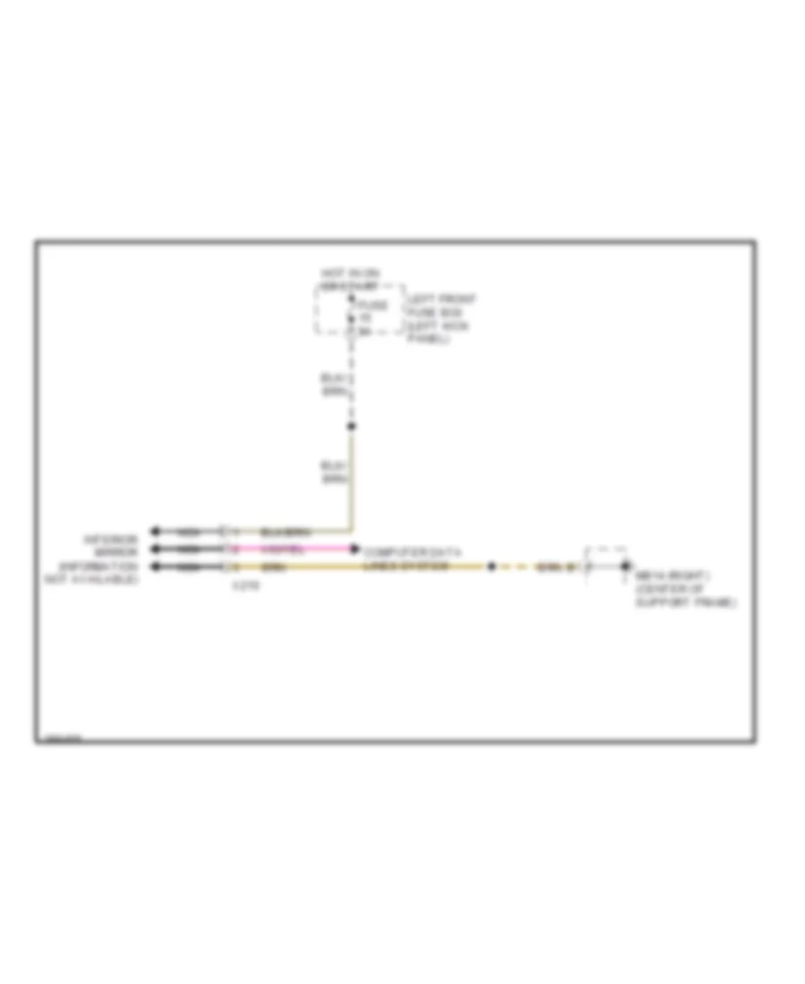
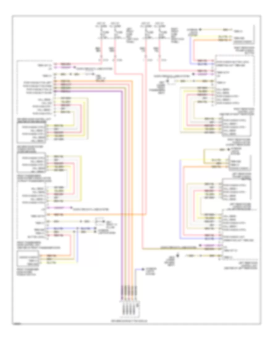
COMPUTER DATA LINES
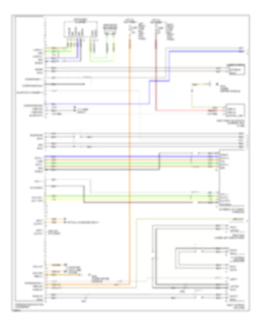
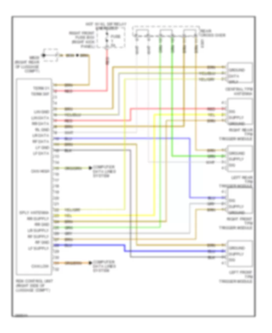
Computer Data Lines Wiring Diagram (1 of 3) for Porsche Panamera 4 2013
List of elements for Computer Data Lines Wiring Diagram (1 of 3) for Porsche Panamera 4 2013:
- (info not available)
- (info not available) interior mirror
- (left side of luggage compt) gateway control unit
- Alarm siren
- Backup camera control unit (right side of luggage compt)
- Can chassis high
- Can chassis low
- Can comfort high
- Can comfort low
- Can crash high
- Can crash low
- Can drive high
- Can drive low
- Can high
- Can high a
- Can low
- Can mmi high
- Can mmi low
- Chassis high
- Chassis low
- Comfort high
- Comfort low
- Data
- Diagnostics high
- Diagnostics low
- Driver's door control unit (center of driver door)
- Driver's seat control unit
- Electronic ignition lock
- Electronic steering column adjustment control unit
- Front bcm (under left side of dash)
- Front passenger's door control unit (center of passenger door)
- Front passenger's seat control unit
- Front wiper motor
- Homelink control umit (center front of engine compt)
- Left rear door control unit b (center of rear door)
- Lin
- Lin 1
- Lin 2
- Lin 3
- Lin main fuse box
- Main fuse box (center front of engine compt) c
- Mb27 (left rear of luggage compt)
- Nca
- Power lift gate control unit (center rear of luggage compt)
- Rain sensor (top center of windshield)
- Rdk control unit (right side of luggage compt)
- Rear bcm (left side of luggage compt)
- Right rear door control unit b
- Roof console
- Rotary light switch
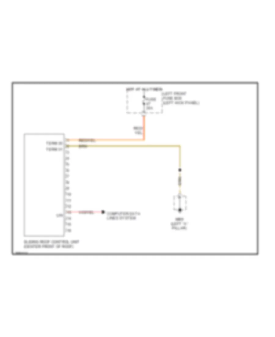
- Sliding roof control unit (center front of roof)
- Steering column lock
- Steering column switching module
- Term 15
- Term 30
- Term 31
- Trailer hitch control unit (right side of luggage compt)
- X0101
- X110
- X120
- X130
- X140
- X160
- X170
- X210
- X242
- X320
- X741
- X820
Computer Data Lines Wiring Diagram (2 of 3) for Porsche Panamera 4 2013
List of elements for Computer Data Lines Wiring Diagram (2 of 3) for Porsche Panamera 4 2013:
- (hybrid) spindle actuator
- Can drive high
- Can drive low
- Can high
- Can low
- Cluster sensor (under front of floor console)
- Dme 2nd generation dfi control unit (hybrid)
- Electrical power drive (hybrid)
- Epb control unit (right side of luggage compt)
- Fuse 5a
- High
- High voltage battry system (hybrid)
- Hot at all times
- Hot w/ kl 15 relay energized
- Low
- Parking assistance control unit
- Parking heater control unit (lower left rear of engine compt)
- Pasm level control unit (left side of luggage compt)
- Porsche dynamic chassis control unit
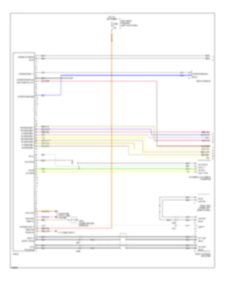
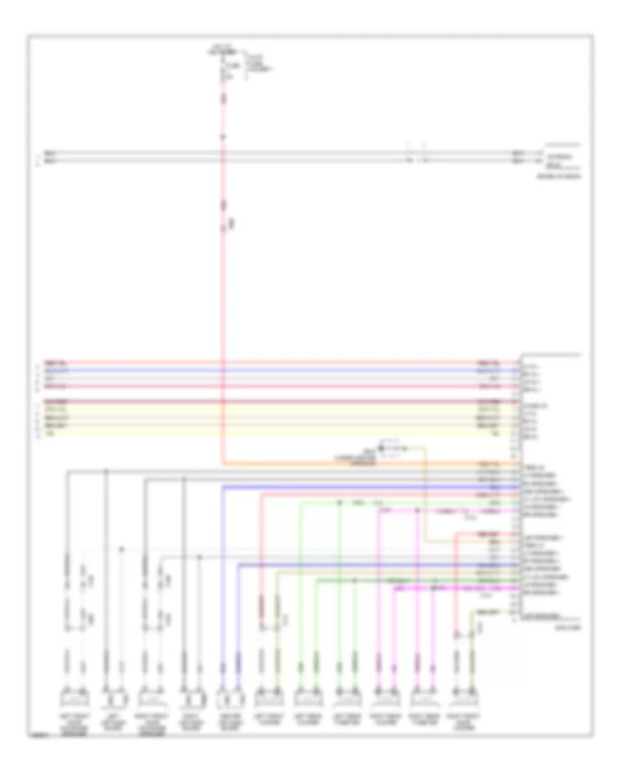
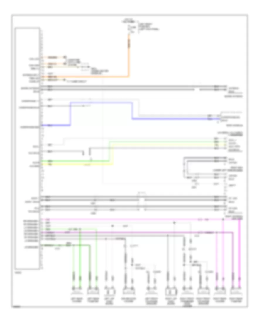
- Radio
- Rear differential lock control unit (left side of luggage compt)
- Rear fuse box (row b)
- X901
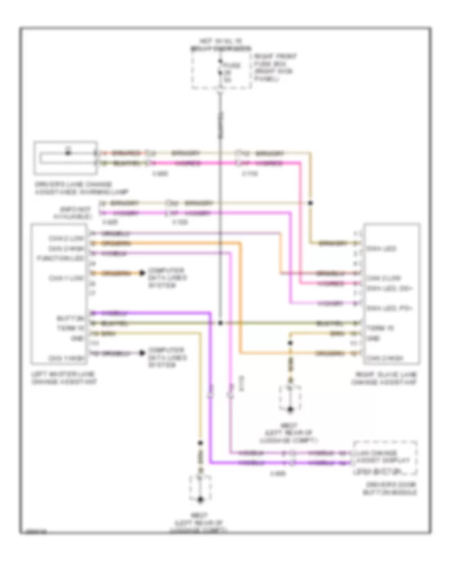
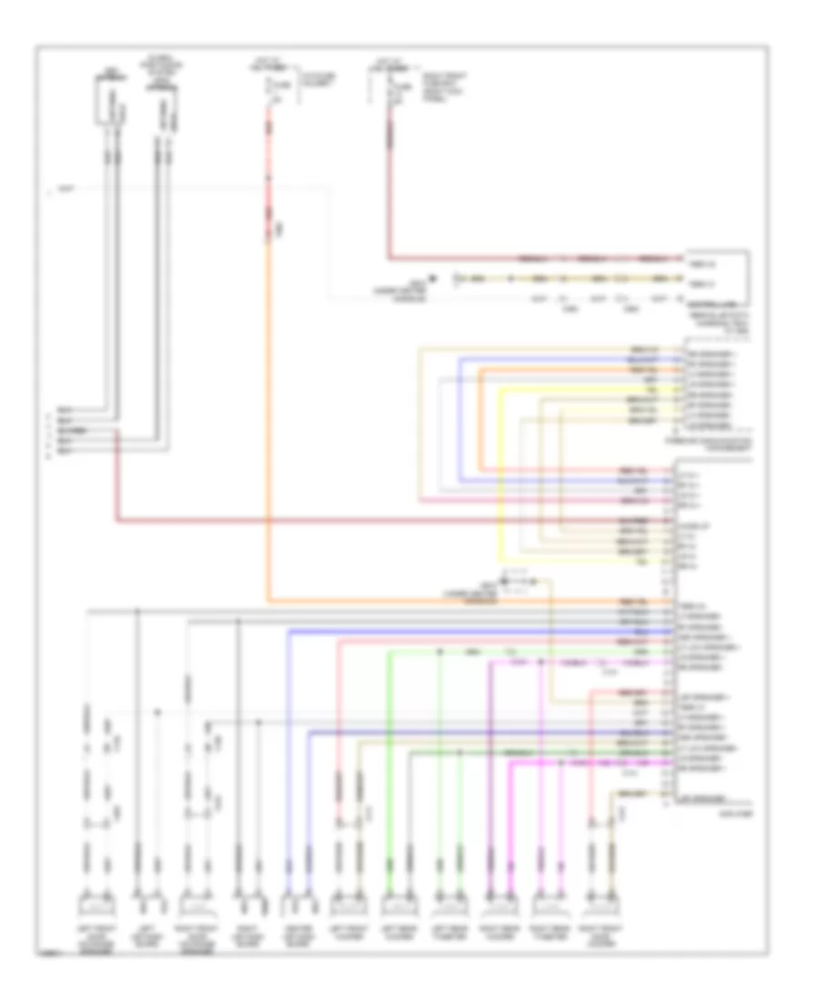
Computer Data Lines Wiring Diagram (3 of 3) for Porsche Panamera 4 2013
List of elements for Computer Data Lines Wiring Diagram (3 of 3) for Porsche Panamera 4 2013:
- A/c control unit
- Acc control unit (center front of engine compt)
- Air bag control unit (under center console)
- Can
- Can distributor (if equipped)
- Can high
- Can low
- Diagnostic plug socket (under left side of dash)
- Dispo line acl
- Dme control unit (except hybrid) (right rear of engine compt)
- Fuse 5a
- Gnd
- High
- High 1
- Hot at all times
- Hot w/ kl 15 relay energized
- Instrument cluster
- Lane change assistant master
- Left front fuse box (left kick panel)
- Left headlights
- Low
- Low 1
- Mb09 (left "a" pillar)
- Mb11 (right "a" pillar)
- Pcm (center of dash)
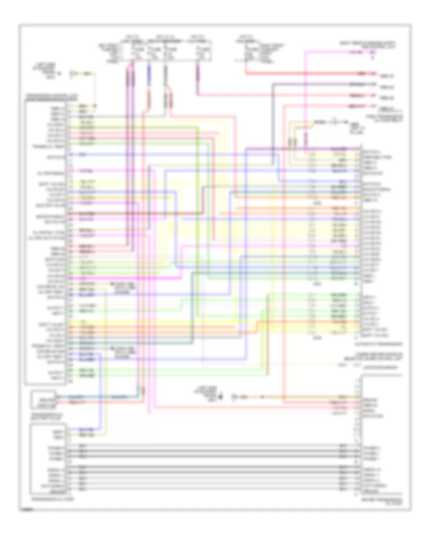
- Pdk control unit (left side of dash)
- Power steering pump (hybrid)
- Psm control unit (right side of engine compt)
- Right front fuse box (right kick panel)
- Right headlight
- Selector lever control unit (under center console)
- Sig
- Stop watch
- Transmission control unit (aisin transmission) 8-gear
- X010
COOLING FAN
Cooling Fan Wiring Diagram, Except Hybrid for Porsche Panamera 4 2013
List of elements for Cooling Fan Wiring Diagram, Except Hybrid for Porsche Panamera 4 2013:
- (left front of engine compt)
- 3.6l & 4.8l
- 4.8l twin turbo
- A/c operating unit
- Can h
- Can high 1
- Can l
- Can low 1
- Computer data lines system
- Cooling water
- Cooling water fan (3.6l & 4.8l)
- Cooling water fan (4.8l twin turbo)
- Ctrl 1
- Dme control unit (right rear of engine compt)
- Engine compartment temperature sensor
- Engine compt temp
- Engine controls system
- Engine sensor
- Fuse 10a
- Fuse 5a
- Fuse 80a
- Ground
- Hot at all times
- Hot w/ dem1 relay energized
- Left front fuse box
- Mb07 (left rear of engine compt)
- Mb3
- Midi fuse box
- Pump rly
- Pwm
- Red
- Right front fuse box
- Sig
- Term 30
- Term 31
- Term 87
- Water circulating pump
- Water circulating pump relay
Cooling Fan Wiring Diagram, Hybrid for Porsche Panamera 4 2013
List of elements for Cooling Fan Wiring Diagram, Hybrid for Porsche Panamera 4 2013:
- (right rear of engine compt) mb08
- A/c control unit
- Air conditioning relay
- Battery cooling valve
- Can hi
- Can high
- Can lo
- Can low
- Computer data lines system
- Coolant return temperature sensor
- Coolant temp 1
- Coolant temp sens
- Coolant temperature sensor
- Dme control unit (right rear of engine compt)
- Engine compartment temperature sensor
- Engine compt temp
- Engine controls system
- Fan 1 pwm
- Fan 2 pwm
- Fan relay
- Feedback
- Fuse 15a
- Fuse 25a
- Fuse 5a
- High volt battery system
- Hot at all times
- Hot w/ terminal 15 relay energized
- Left battery fan
- Left front fuse box (left kick panel)
- Mb26 (right rear of luggage compt)
- Mb27 (left rear of luggage compt)
- Pwm
- Rear fuse box (row c)
- Red
- Right battery fan
- Sens gnd
- Shutoff valve
- Sply 5v
- Term 30
- Term 31
- Valve open
- X031
- X035
- X902
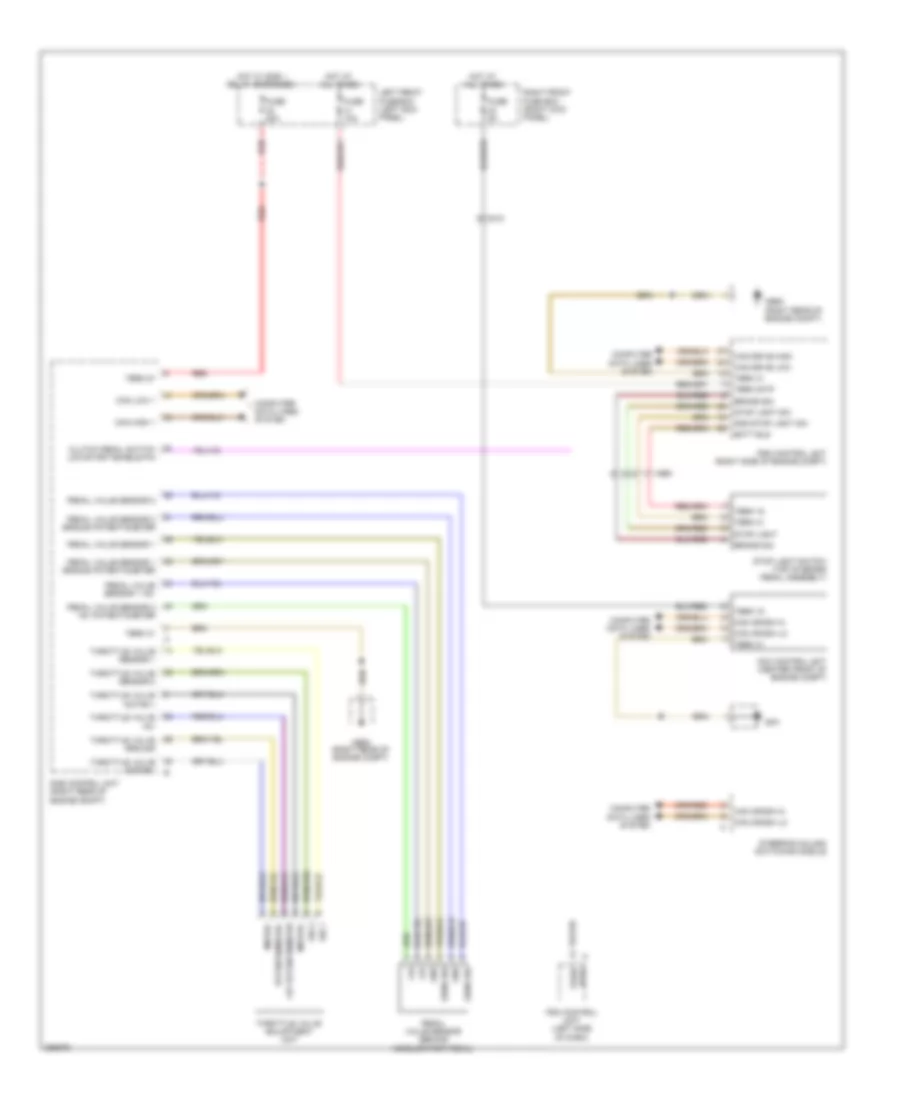
CRUISE CONTROL
Cruise Control Wiring Diagram, Except Hybrid for Porsche Panamera 4 2013
List of elements for Cruise Control Wiring Diagram, Except Hybrid for Porsche Panamera 4 2013:
- +5v
- +5v potentiometer
- A ntrl
- Acc control unit (center front of engine compt)
- Batt bls
- Brake sig
- Can crash hi
- Can crash lo
- Can drive high
- Can drive low
- Can high 1
- Can low 1
- Clutch pedal switch low/start enable p/n
- Computer data lines system
- Dme control unit (right rear of engine compt)
- Fuse 10a
- Fuse 20a
- Fuse 5a
- Gnd
- Gnd stop light sw
- Gp4
- Hot at all times
- Hot w/ dme 1 relay energized
- Left front fuse box (left kick panel)
- Mb06 (right rear of engine compt)
- Mb08 (right rear of engine compt)
- Motor+
- Motor-
- Park/
- Pdk control unit (left side of dash)
- Pedal value sensor (behind accelerator pedal)
- Pedal value sensor 1
- Pedal value sensor 1 +5v
- Pedal value sensor 1 ground potentiometer
- Pedal value sensor 2
- Pedal value sensor 2 ground potentiometer
- Pedal valve sensor 2 +5v potentiometer
- Potentiometer-
- Psm control unit (right side of engine compt)
- Red
- Right front fuse box (right kick panel)
- Sens sig
- Sig 1
- Sig 2
- Steering column switching module
- Stop light
- Stop light sw
- Stop light switch (top of brake pedal assembly)
- Term 15
- Term 30tp
- Term 31
- Term 87
- Throttle valve +5v
- Throttle valve adjustment unit
- Throttle valve ground
- Throttle valve motor +
- Throttle valve motor -
- Throttle valve sensor 1
- Throttle valve sensor 2
- X010
- X960
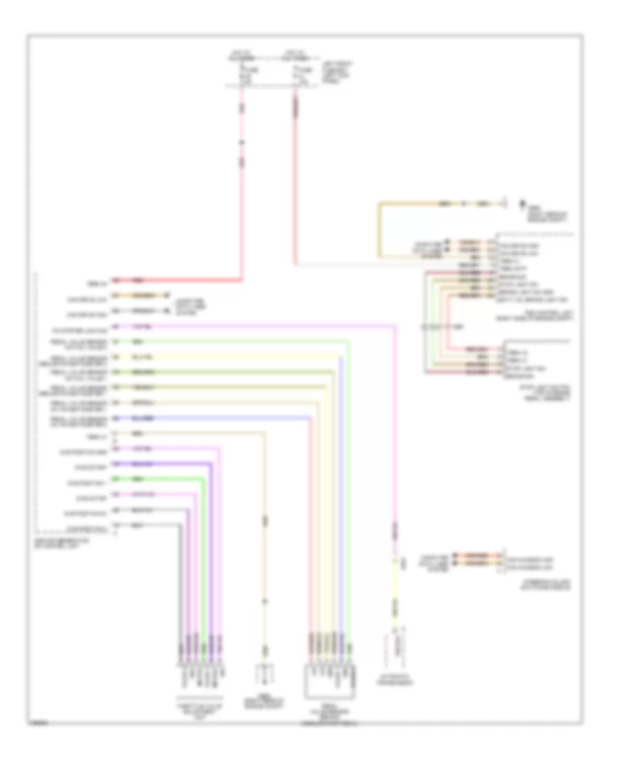
Cruise Control Wiring Diagram, Hybrid for Porsche Panamera 4 2013
List of elements for Cruise Control Wiring Diagram, Hybrid for Porsche Panamera 4 2013:
- +5v
- Automatic transmission
- Batt vol brake light sw
- Brake light sw gnd
- Brake sig
- Can chassis high
- Can chassis low
- Can drive high
- Can drive low
- Computer data lines system
- Dme 2nd generation dfi control unit
- Dve motor+
- Dve motor-
- Dve position 1
- Dve position 2
- Dve position 5v
- Dve position gnd
- Fuse 10a
- Fuse 5a
- Gnd
- Hot at all times
- Left front fuse box (left kick panel)
- Mb06 (right rear of engine compt)
- Mb08 (right rear of engine compt)
- Motor+
- Motor-
- P/n pos
- P/n strter lock sig
- Pedal value sensor (behind accelerator pedal)
- Pedal value sensor actual value 1
- Pedal value sensor actual value 2
- Pedal value sensor ground potentiometer 1
- Pedal value sensor ground potentiometer 2
- Pedal valve sensor +5v potentiometer 1
- Pedal valve sensor +5v potentiometer 2
- Psm control unit (right side of engine compt)
- Red
- Sig+
- Sig-
- Steering column switching module
- Stop light sw
- Stop light switch (top of brake pedal assembly)
- Term 15
- Term 30
- Term 30tp
- Term 31
- Throttle valve adjustment unit
- Value 1
- Value 2
- X043
- X960
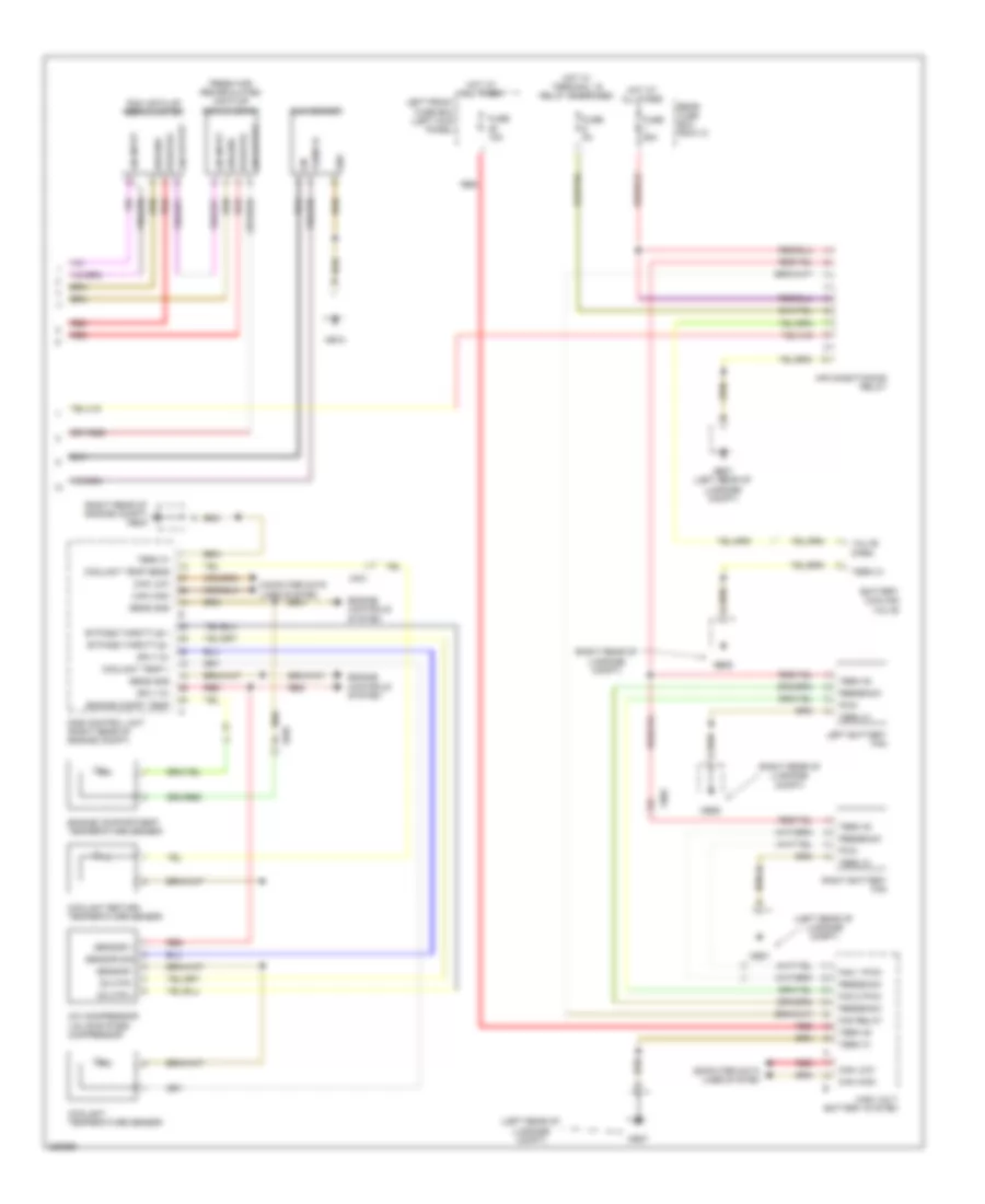
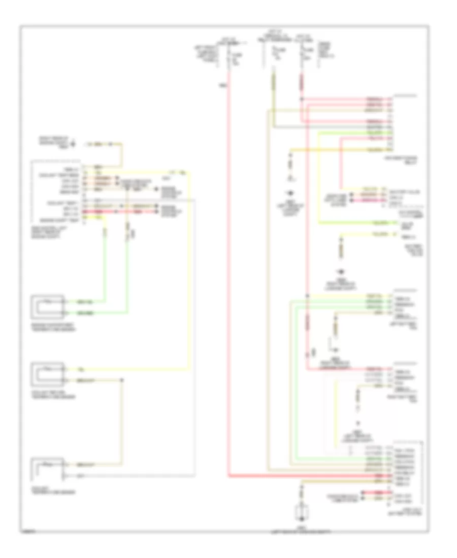
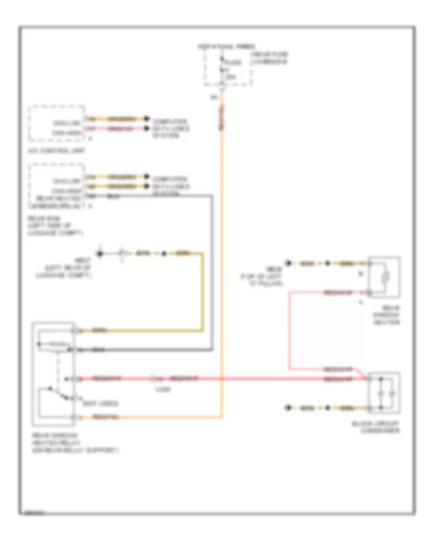
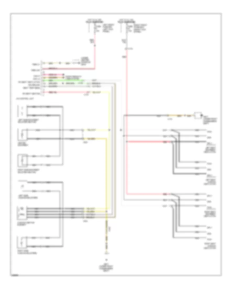
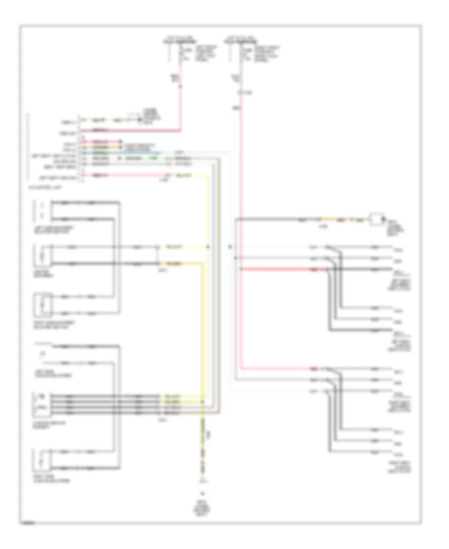
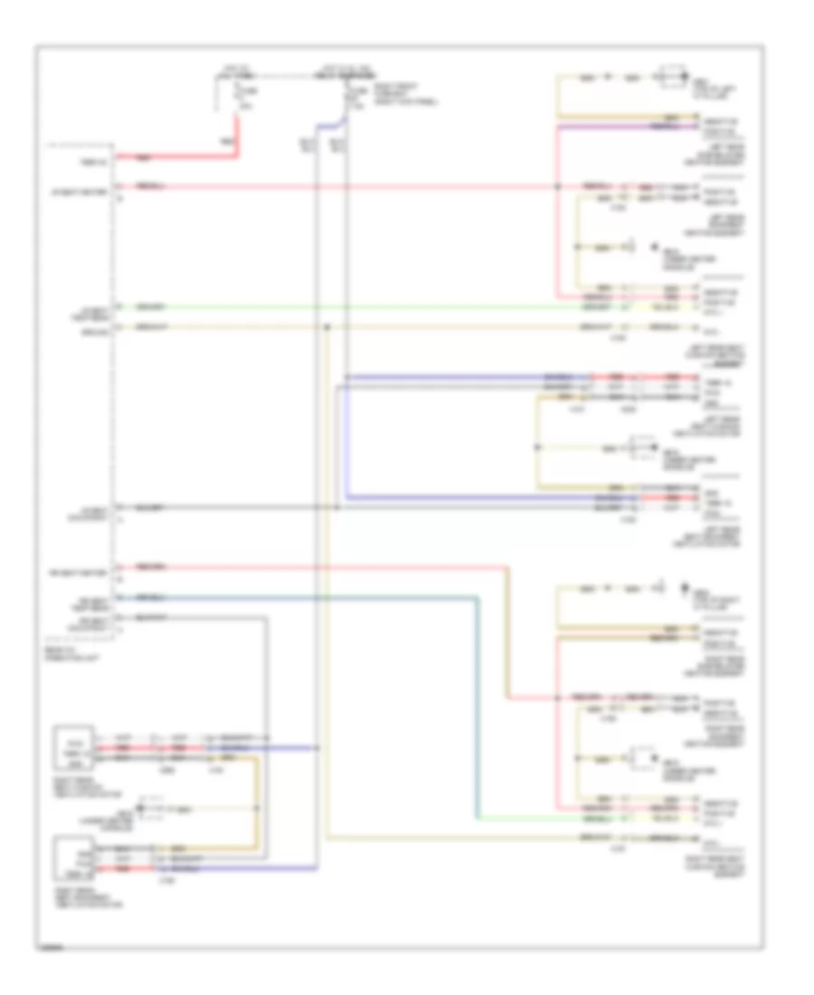
DEFOGGERS
Defogger Wiring Diagram for Porsche Panamera 4 2013
List of elements for Defogger Wiring Diagram for Porsche Panamera 4 2013:
- (not used)
- A/c control unit
- Block circuit condenser
- Can high
- Can high rear heated window relay a
- Can low
- Computer data lines system
- Fuse 25a
- Hot at all times
- Mb27 (left rear of luggage compt)
- Mb28 (top of left "c" pillar)
- Rear bcm (left side of luggage compt)
- Rear fuse carrier b
- Rear window heated relay (on rear relay support)
- Rear window heater
- X240
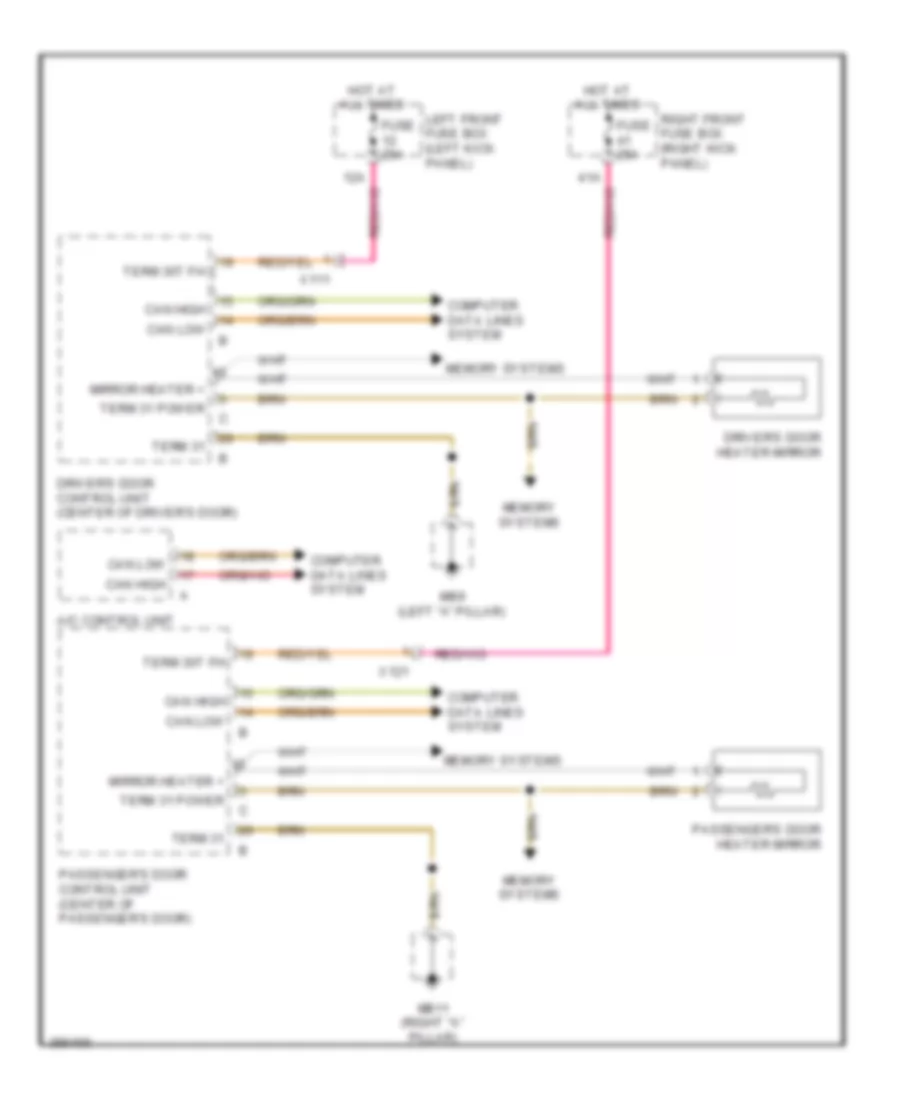
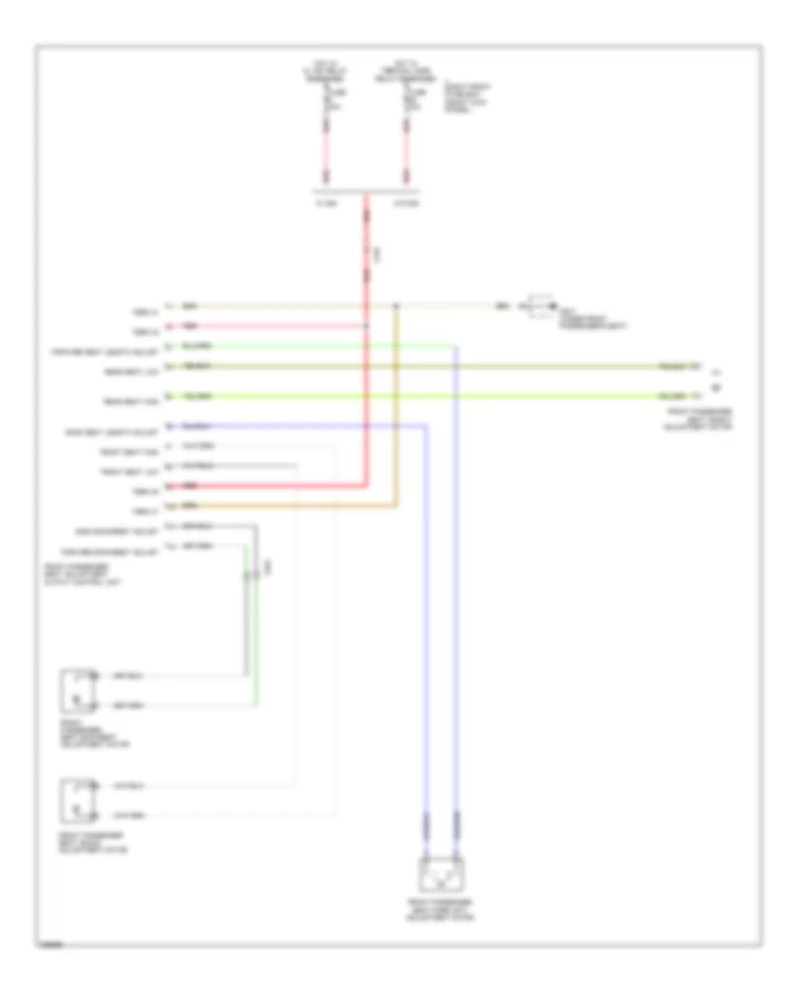
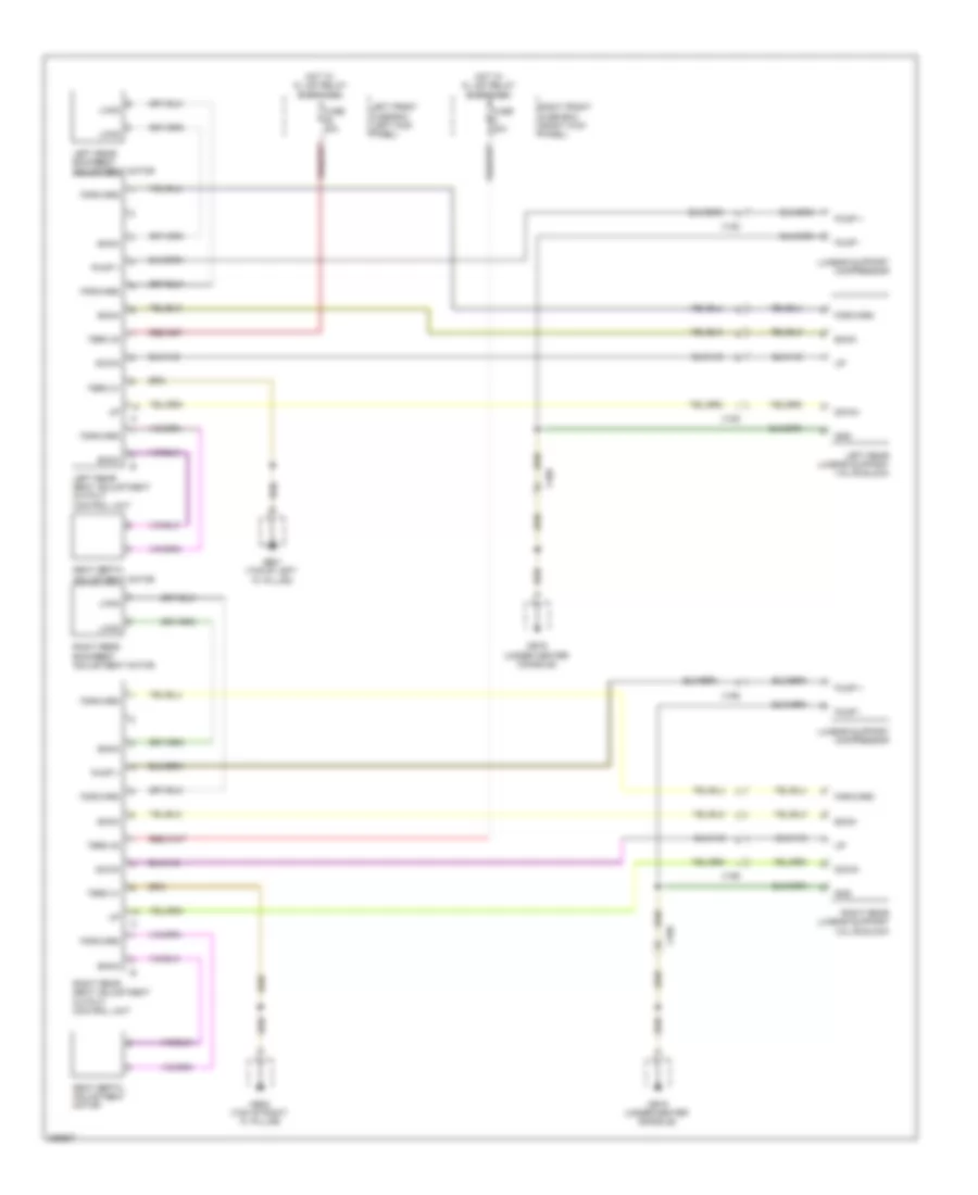
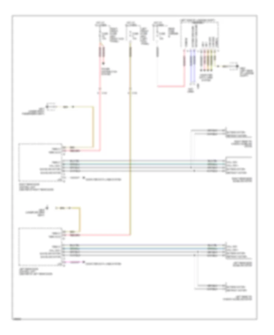
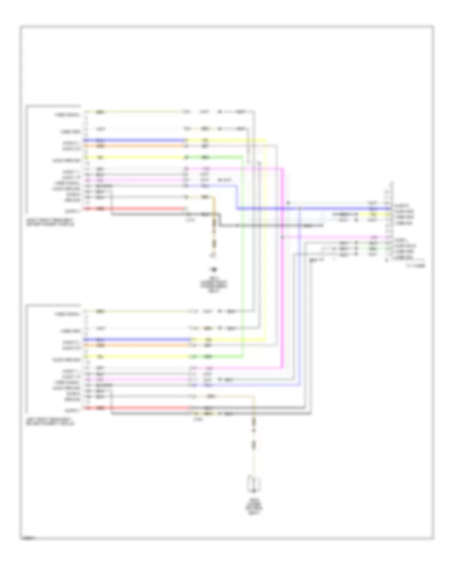
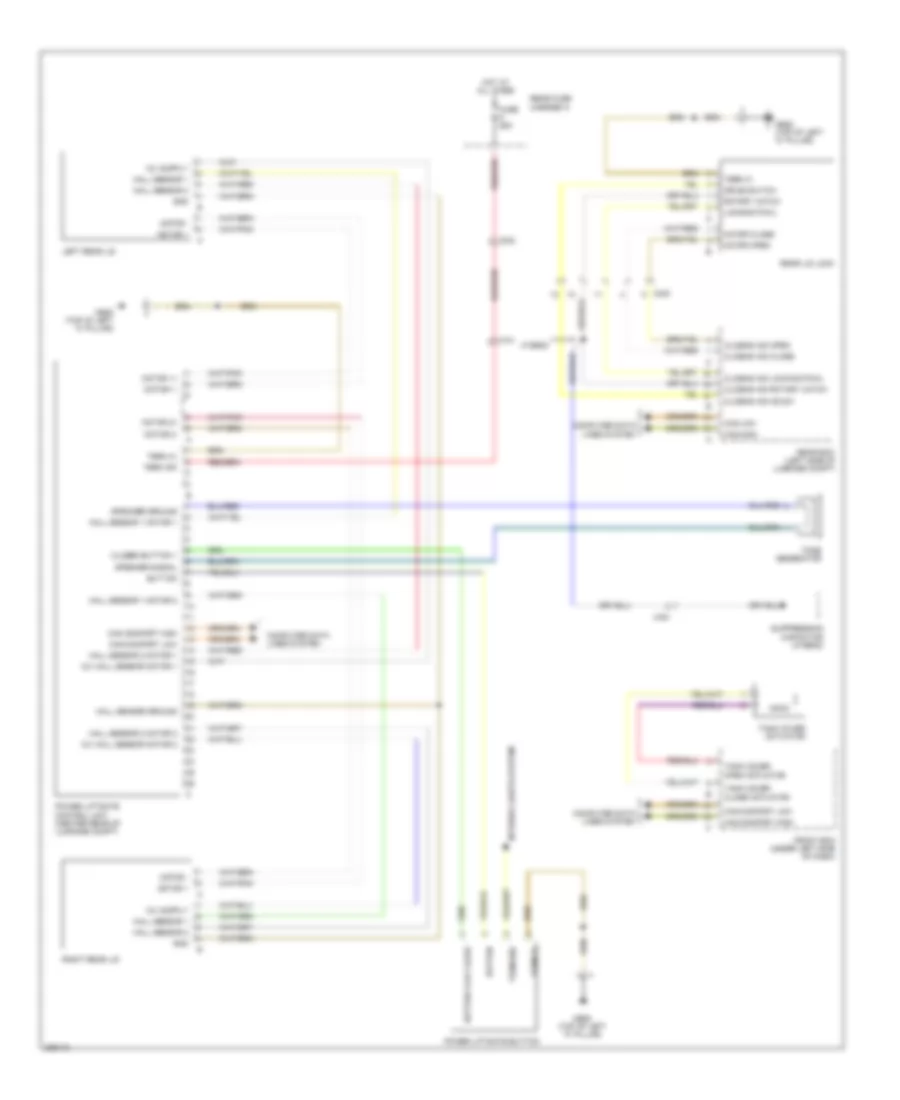
Heated Mirrors Wiring Diagram for Porsche Panamera 4 2013
List of elements for Heated Mirrors Wiring Diagram for Porsche Panamera 4 2013:
- 12a
- 41a
- A/c control unit
- Can high
- Can low
- Computer data lines system
- Driver's door control unit (center of driver's door)
- Driver's door heater mirror
- Fuse 25a
- Hot at all times
- Left front fuse box (left kick panel)
- Mb11 (right "a" pillar)
- Mb9 (left "a" pillar)
- Memory systems
- Mirror heater +
- Passenger's door control unit (center of passenger's door)
- Passenger's door heater mirror
- Right front fuse box (right kick panel)
- Term 30t fh
- Term 31
- Term 31 power
- X111
- X121
ELECTRONIC POWER STEERING
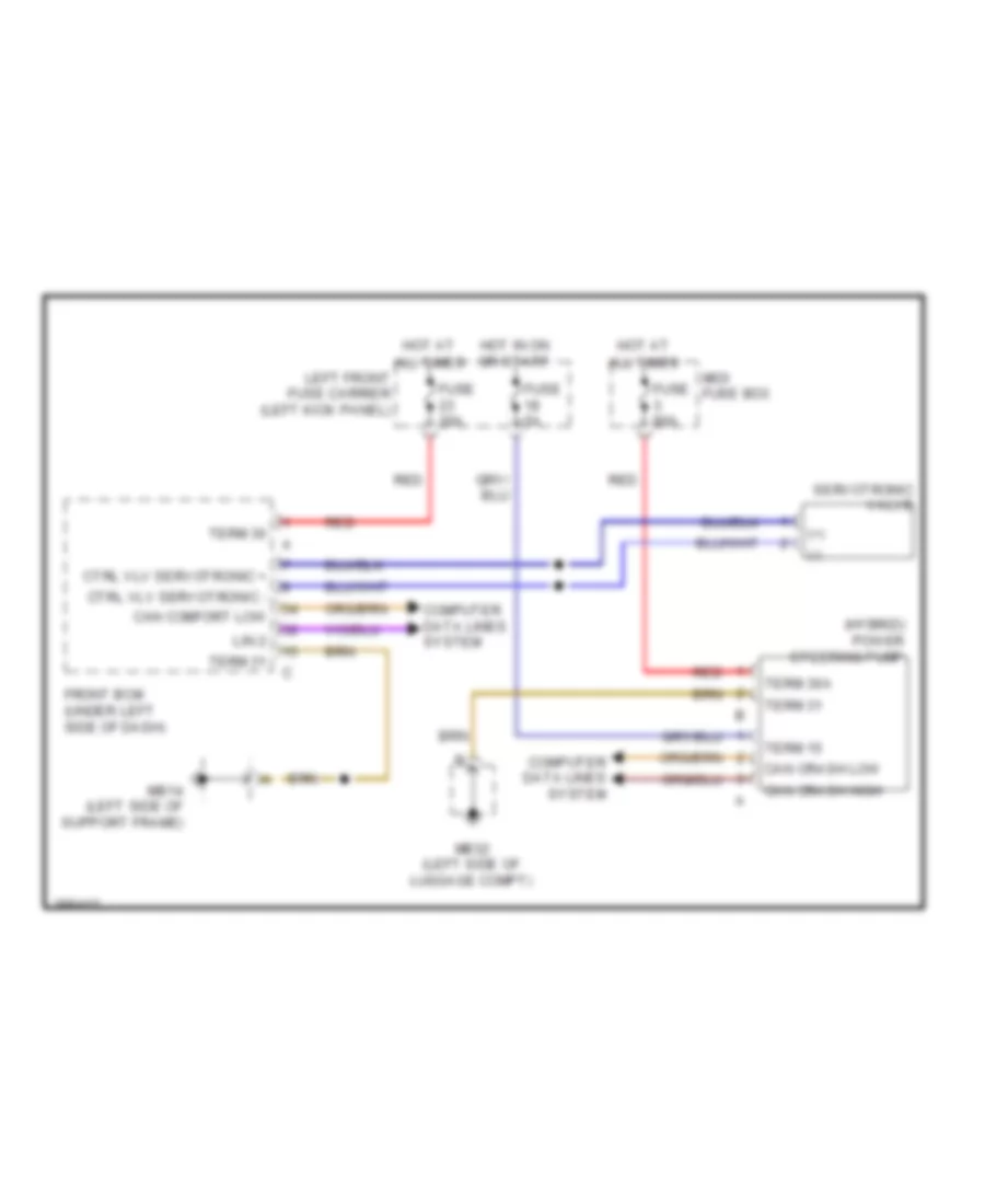
Electronic Power Steering Wiring Diagram for Porsche Panamera 4 2013
List of elements for Electronic Power Steering Wiring Diagram for Porsche Panamera 4 2013:
- (+)
- (-)
- (hybrid) power steering pump
- All times
- Can comfort low
- Can crash high
- Can crash low
- Computer data lines system
- Ctrl vlv servotronic +
- Ctrl vlv servotronic -
- Front bcm (under left side of dash)
- Fuse 30a
- Fuse 5a
- Fuse 80a
- Hot at
- Hot in on or start
- Left front fuse carrier (left kick panel)
- Lin 2
- Mb14 (left side of support frame)
- Mb32 (left side of luggage compt)
- Midi fuse box
- Red
- Servotronic valve
- Term 15
- Term 30
- Term 30a
- Term 31
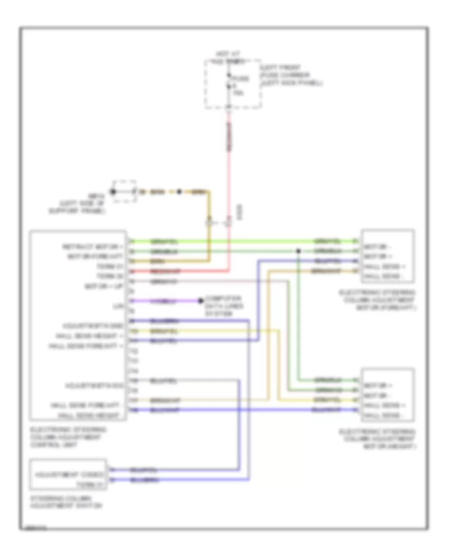
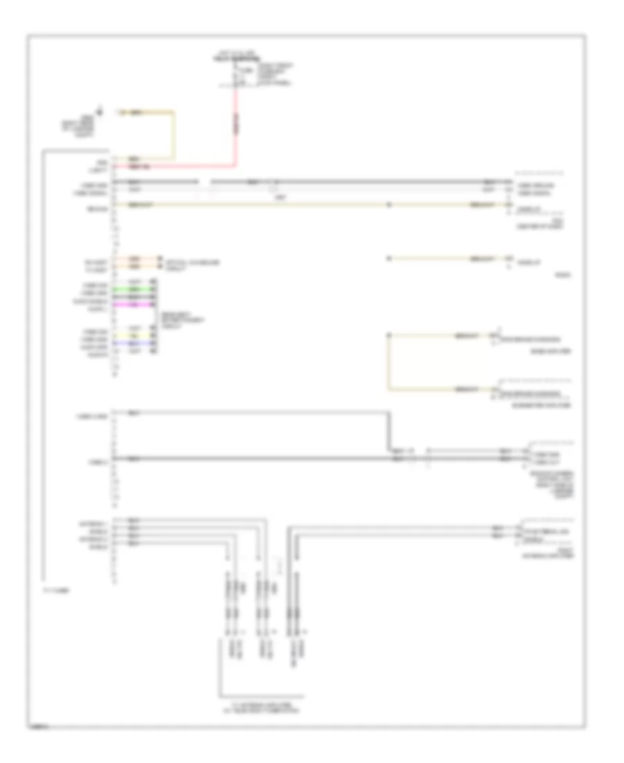
Power Tilt Steering Column Wiring Diagram for Porsche Panamera 4 2013
List of elements for Power Tilt Steering Column Wiring Diagram for Porsche Panamera 4 2013:
- Adjustm btn gnd
- Adjustm btn sig
- Adjustment coded
- Computer data lines system
- Electronic steering column adjustment control unit
- Electronic steering column adjustment motor (fore/aft)
- Electronic steering column adjustment motor (height)
- Fuse 15a
- Hall sens +
- Hall sens -
- Hall sens fore/aft +
- Hall sens fore/aft -
- Hall sens height +
- Hall sens height -
- Hot at all times
- Left front fuse carrier (left kick panel)
- Lin
- Mb14 (left side of support frame)
- Motor +
- Motor + up
- Motor -
- Motor-fore/aft
- Retract motor +
- Steering column adjustment switch
- Term 30
- Term 31
- X820
ELECTRONIC SUSPENSION
Dynamic Chassis Control Wiring Diagram for Porsche Panamera 4 2013
List of elements for Dynamic Chassis Control Wiring Diagram for Porsche Panamera 4 2013:
- (left rear of luggage compt) pdcc control unit
- Can chassis high
- Can chassis low
- Computer data lines system
- Fr axle fsv valve +
- Fr axle fsv valve -
- Fr axle pdb valve +
- Fr axle pdb valve -
- Fr axle press sens 1 +5v
- Fr axle press sens 1 gnd
- Fr axle press sens 1 sig
- Fr axle press sens 2 +5v
- Fr axle press sens 2 gnd
- Fr axle press sens 2 sig
- Fr axle rv valve +
- Fr axle rv valve -
- Front axle fsv valve v1
- Front axle pdb valve v3
- Front axle rv valve v2
- Fuse f11 10a
- Fuse f12 10a
- Gnd
- Hot at all times
- Hot in on or start
- Mb27 (left rear of luggage compt)
- Mbp9
- Pdcc pressure sensor a1
- Pdcc pressure sensor a2
- Pdcc pressure sensor b1
- Pdcc pressure sensor b2
- Rear axle pdb valve v5
- Rear axle rv valve v4
- Rear fuse carrier a
- Rear fuse carrier b
- Red
- Rr axle pdb valve +
- Rr axle pdb valve -
- Rr axle press sens 1 +5v
- Rr axle press sens 1 gnd
- Rr axle press sens 1 sig
- Rr axle press sens 2
- Rr axle press sens 2 gnd
- Rr axle press sens 2 sig
- Rr axle rv valve +
- Rr axle rv valve -
- Sig
- Sply
- Sply oil
- Steering level sensor
- Term 30
- Term 31
- Valve hs
- Valve ls
- Wake-up line
- X600
- X610
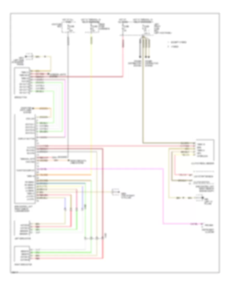
Electronic Level Control Wiring Diagram (1 of 2) for Porsche Panamera 4 2013
List of elements for Electronic Level Control Wiring Diagram (1 of 2) for Porsche Panamera 4 2013:
- (on rear relay support) compressor unit pasm relay
- (right rear of front wheelwell) right rear height sensor
- +12v actuation air-spring valve
- +5v
- 12v
- 12v hs
- 12v ls
- A gnd
- Acceleration sensor rear gnd
- Acceleration sensor rear sgn
- Acceleration sensor rear sply
- Actuation air-spring valve fl -
- Actuation air-spring valve fr-
- Actuation air-spring valve rl -
- Actuation air-spring valve rr -
- Additional volume rl+
- Additional volume rl-
- Additional volume rr+
- Additional volume rr-
- B term 31
- Blow off valve -
- Changeover valve 1 -
- Changeover valve 2
- Compressor relay high
- Compressor relay low
- Fl-
- Fr-
- Fuse f1 40a
- Fuse f7 5a
- Gnd
- Gnd press sens
- Gnd sens
- Ground
- High
- Hot at all times
- Hot in on or start
- Left rear shock absorbers valve (w/ 475/350/351) (base of left rear shock absorbers)
- Level sensor rl sig
- Level sensor rl+
- Level sensor rl-
- Level sensor rr sig
- Level sensor rr+
- Level sensor rr-
- Low
- Maxi fuse
- Mb27 (left rear of luggage compt)
- Pasm control unit (left side of luggage compt)
- Pwm
- Rear acceleration sensor
- Rear fuse carrier b
- Red
- Right rear shock absorbers valve (w/ 475/350/351) (base of right rear shock absorbers)
- Rl-
- Rr-
- Shock absorbers valve rl+
- Shock absorbers valve rl-
- Shock absorbers valve rr+
- Shock absorbers valve rr-
- Sig
- Sig door
- Sig press sens
- Signal temp sens compressor
- Solenoid block
- Sply press sens
- Super charger level control
- Temperature sens compressor -
- Term 15
- Term 30
- Term 31
- Term 85
- Term 86
- Term 87
- Umschaltventil 1, 2
- Valve 1 gnd ls
- Valve 2 gnd ls
- X440
- X903
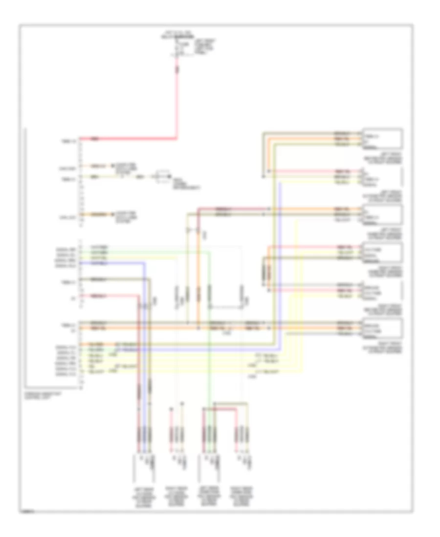
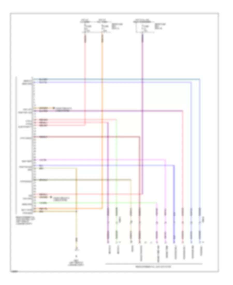
Electronic Level Control Wiring Diagram (2 of 2) for Porsche Panamera 4 2013
List of elements for Electronic Level Control Wiring Diagram (2 of 2) for Porsche Panamera 4 2013:
- (left side of luggage compt) rear bcm
- (under left side of dash) front bcm
- +5v
- +5v sens
- Acceleration sens fl sig
- Acceleration sens fl+
- Acceleration sens fl-
- Acceleration sens fr sig
- Acceleration sens fr+
- Acceleration sens fr-
- Add volume fl+ ctrl unit
- Add volume fl+ veh
- Add volume fl-
- Add volume fl- ctrl unit
- Add volume fl- veh
- Add volume fr+ ctrl unit
- Add volume fr+ veh
- Add volume fr-
- Add volume fr- ctrl unit
- Add volume fr- veh
- Add volume rl+ ctrl unit
- Add volume rl+ veh
- Add volume rl- ctrl unit
- Add volume rl- veh
- Add volume rr+ ctrl unit
- Add volume rr+ veh
- Add volume rr- ctrl unit
- Add volume rr- veh
- Additional volume fl+
- Additional volumefr fr+
- Can high
- Can low
- Computer data lines system
- Fuse f10 25a
- Gnd
- Ground
- High
- Hot at all times
- Input sens
- Left front acceleration sensor (rear of left front wheelwell)
- Left front height sensor
- Left front shock absorbers valve (w/ 350/351) (base of left front shock absorbers)
- Left front shock absorbers valve (w/ 475/350/351) (base of left front shock absorbers)
- Left headlights
- Left rear height sensor
- Left rear shock absorbers valve (w/ 350/351) (base of left rear shock absorbers)
- Level sens gnd
- Level sens sply
- Level sensor fl sig
- Level sensor fl+
- Level sensor fl-
- Level sensor fr sig
- Level sensor fr+
- Level sensor fr-
- Low
- Mb26 (right rear of luggage compt)
- Pasm level control unit (left side of luggage compt)
- Pwm
- Pwm front
- Pwm rear
- Pwm sig
- Rear cross- over
- Rear fuse box
- Right front acceleration sensor (rear of right front wheelwell)
- Right front height sensor
- Right front shock absorbers valve (w/ 350/351) (base of right front shock absorbers)
- Right front shock absorbers valve (w/ 475/350/351) (base of right front shock absorbers)
- Right rear shock absorbers valve (w/ 350/351) (base of right rear shock absorbers)
- Shock absorbers valve fl+
- Shock absorbers valve fl-
- Shock absorbers valve fr+
- Shock absorbers valve fr-
- Sig
- W/ 475/ 350/351
- W/o 475/ 350/351
- W/o 601/ 603/604 & 475/ 350/351
- Wakeup pasm
- X430
- X903
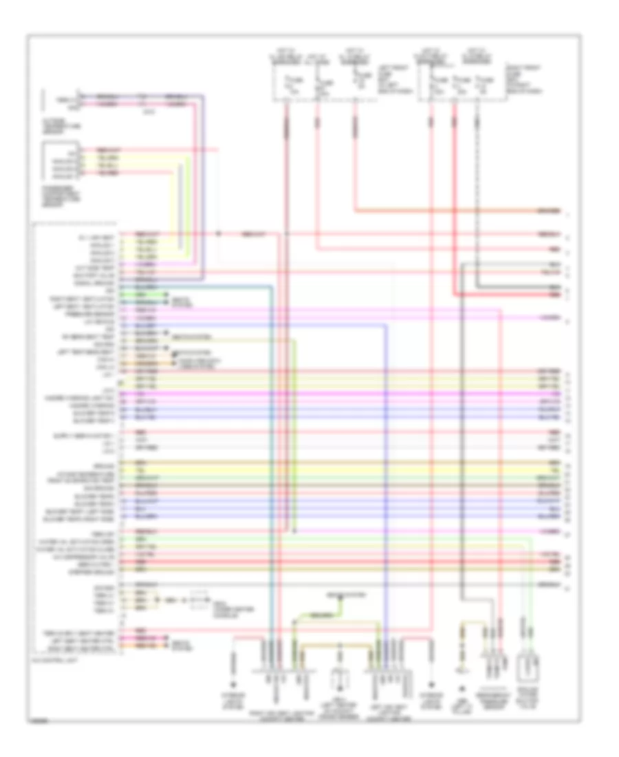
ENGINE PERFORMANCE
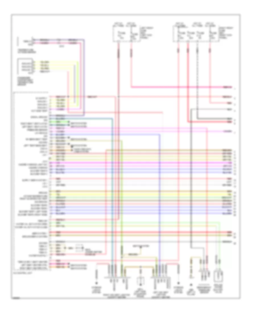
3.0L HYBRID
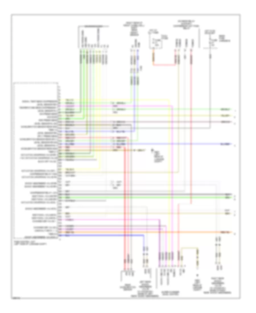
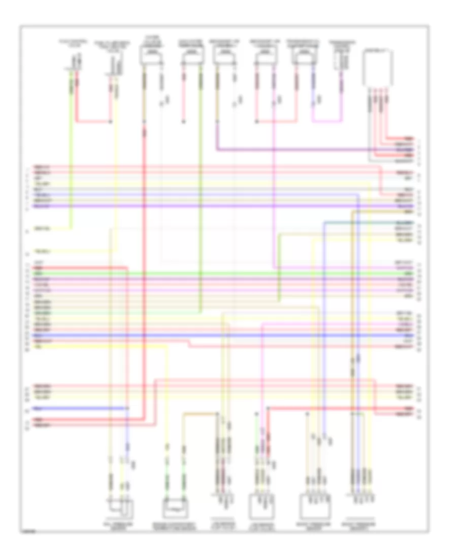
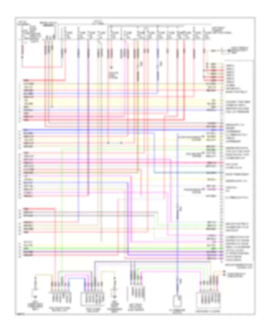
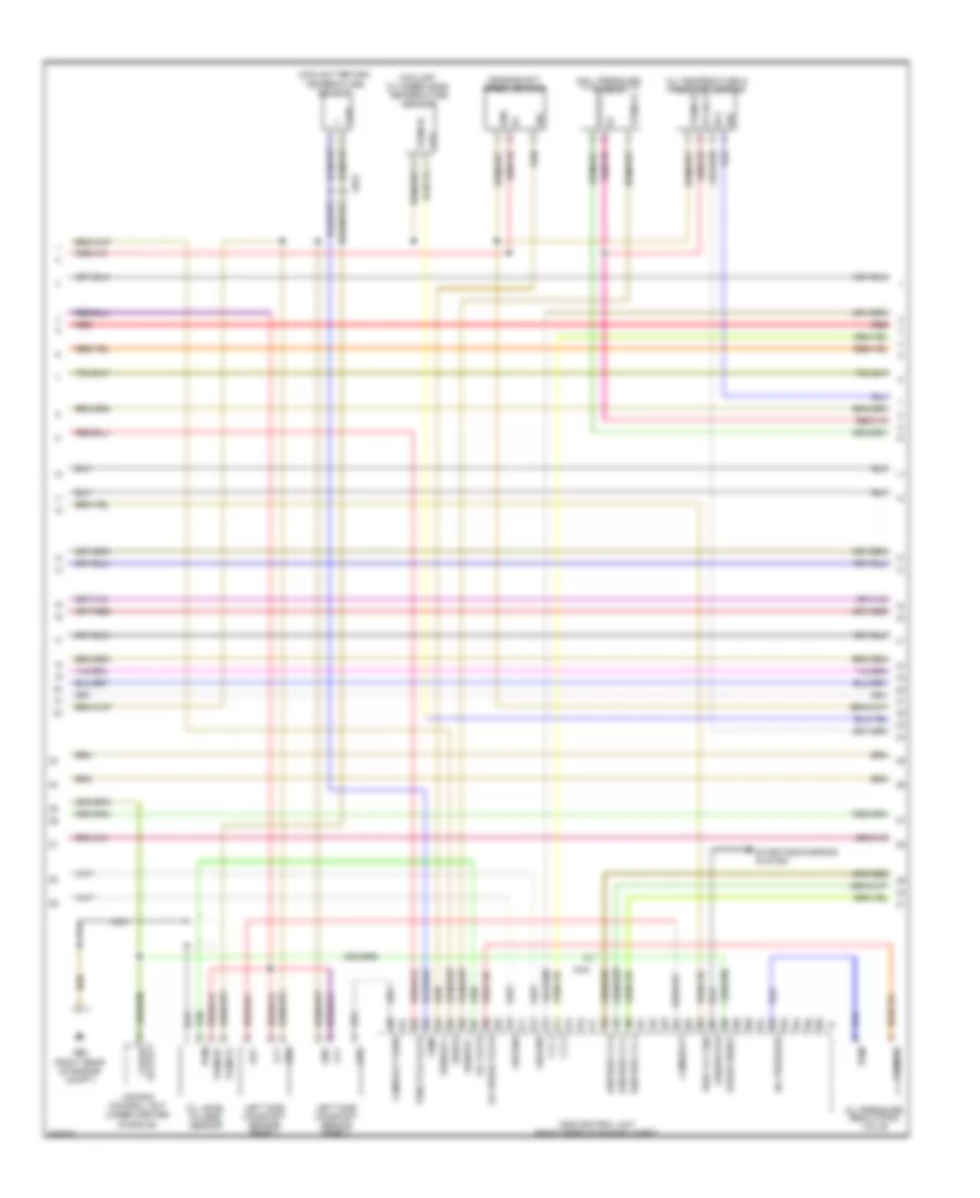
3.0L Hybrid, Engine Performance Wiring Diagram (1 of 7) for Porsche Panamera 4 2013
List of elements for 3.0L Hybrid, Engine Performance Wiring Diagram (1 of 7) for Porsche Panamera 4 2013:
- (top of fuel injector cylinders)
- +5v
- Adjuster
- Adjuster 2
- Camshaft sensor bank 1
- Camshaft sensor bank 2
- Controlr 2 intake
- Cool temp1
- Coolant pump valve
- Crankshaft speed sender
- Crash pwm
- Dme 2nd generation dfi control unit
- Drv pos gnd
- Dve motor
- Dve motor+
- Dve pos 5v
- Dve position 1
- Dve position 2
- Engine temperature
- Flow control valve
- Fuel injector 1
- Fuel injector 2
- Fuel injector 3
- Fuel injector 4
- Fuel injector 5
- Fuel injector 6
- Gnd
- High press rail
- High temp circuit
- Hp inj1 high side
- Hp inj2 high side
- Hp inj3 high side
- Hp inj3 low side
- Hp inj4 high side
- Hp inj4 low side
- Hp inj5 hagh side
- Hp inj6 high side
- Hp inj6 low side
- Ign signal 4
- Ign signal 5
- Ign signal 6
- Ignition sig 1
- Ignition sig 2
- Ignition sig 3
- Inj1 lower side
- Inj2 lower side
- Inj5 lower side
- Input a
- Input b
- Intake cami
- Intake camshaft2
- Knock sens 1
- Knock sens engine
- Knock sensor 1 bank 1
- Knock sensor 2 bank 2
- Know sens gng
- Lt circuit pwm
- Motion fl valve
- Oil pres reg valve
- Oil pressure regulating valve
- Red
- Sens gnd
- Sens gnd anlge
- Sens gnd digital
- Sens suppy 5v
- Sensor +
- Sensor -
- Sensor inputb
- Shutoff valve
- Sig
- Speed crankshaft
- Temp sens+
- Temperature 2
- X031
- X035
- X036
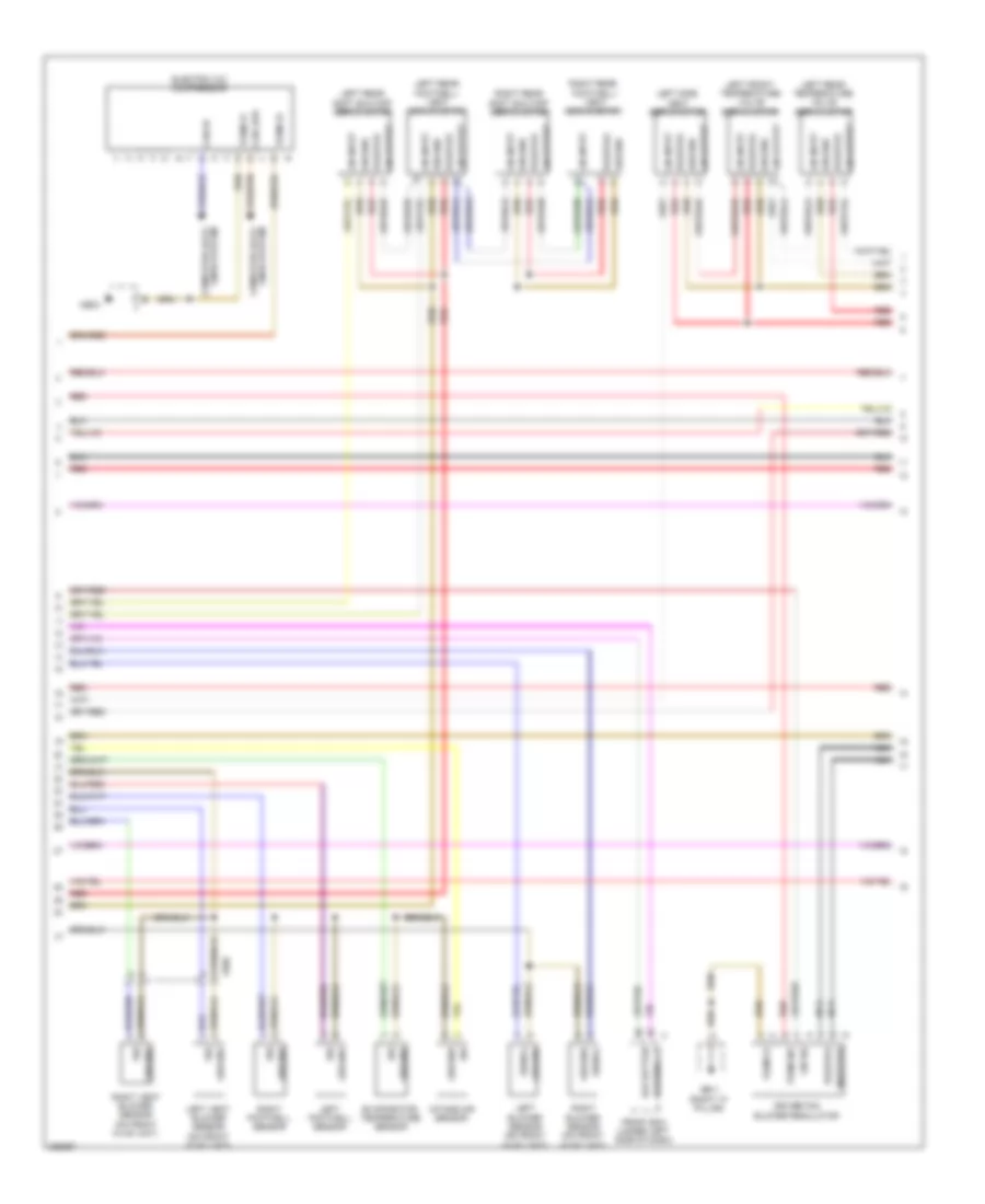
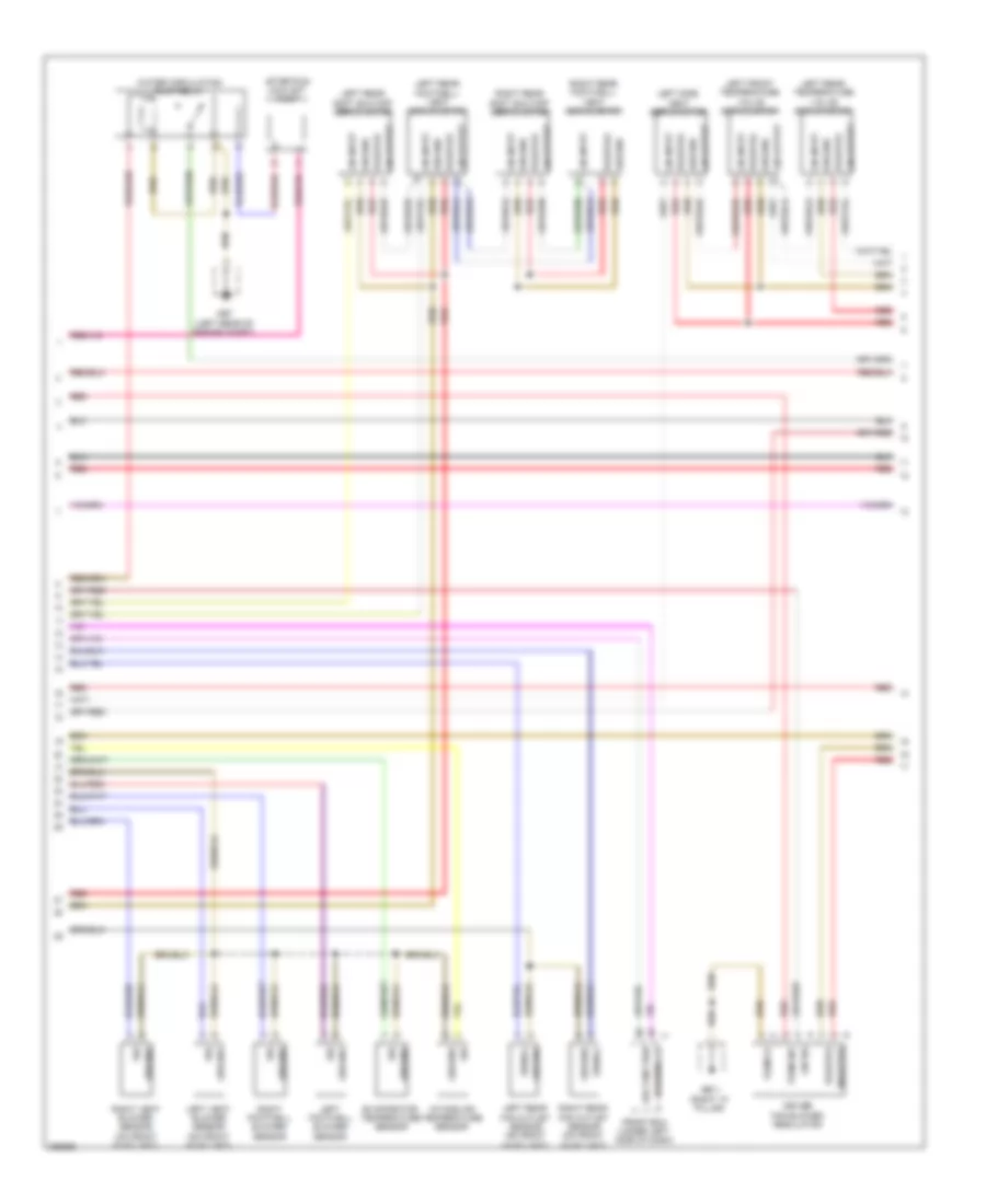
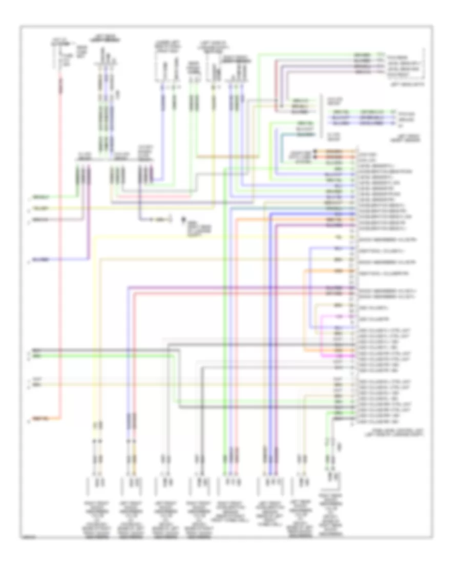
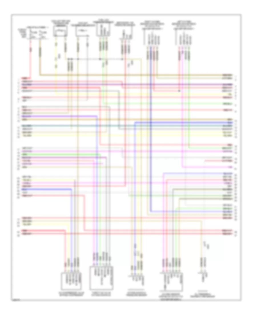
3.0L Hybrid, Engine Performance Wiring Diagram (2 of 7) for Porsche Panamera 4 2013
List of elements for 3.0L Hybrid, Engine Performance Wiring Diagram (2 of 7) for Porsche Panamera 4 2013:
- After run coolant pump
- Bar ignitmodule cylinder 1
- Bar ignitmodule cylinder 2
- Bar ignitmodule cylinder 3
- Bar ignitmodule cylinder 4
- Bar ignitmodule cylinder 5
- Bar ignitmodule cylinder 6
- Camshaft assembly part controller b1
- Camshaft assembly part controller b2
- Engine ground
- Ground
- Ground body
- Ignition signal
- Mb01 (left side of luggage compt)
- Mb03
- Mb05
- Mb08 (right rear of engine compt)
- Oil level sensor
- Output
- Positive
- Pwm
- Red
- Signal
- Term 31
- Term 87
- Vacuum pump
- Valve for tuning flap 1
- Vcc
- Water pump high temperature circuit
- X032
- X037
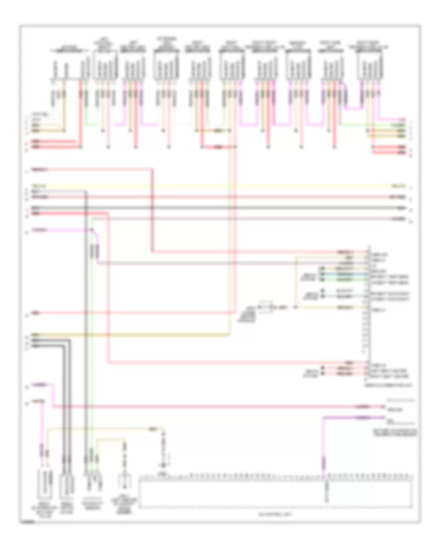
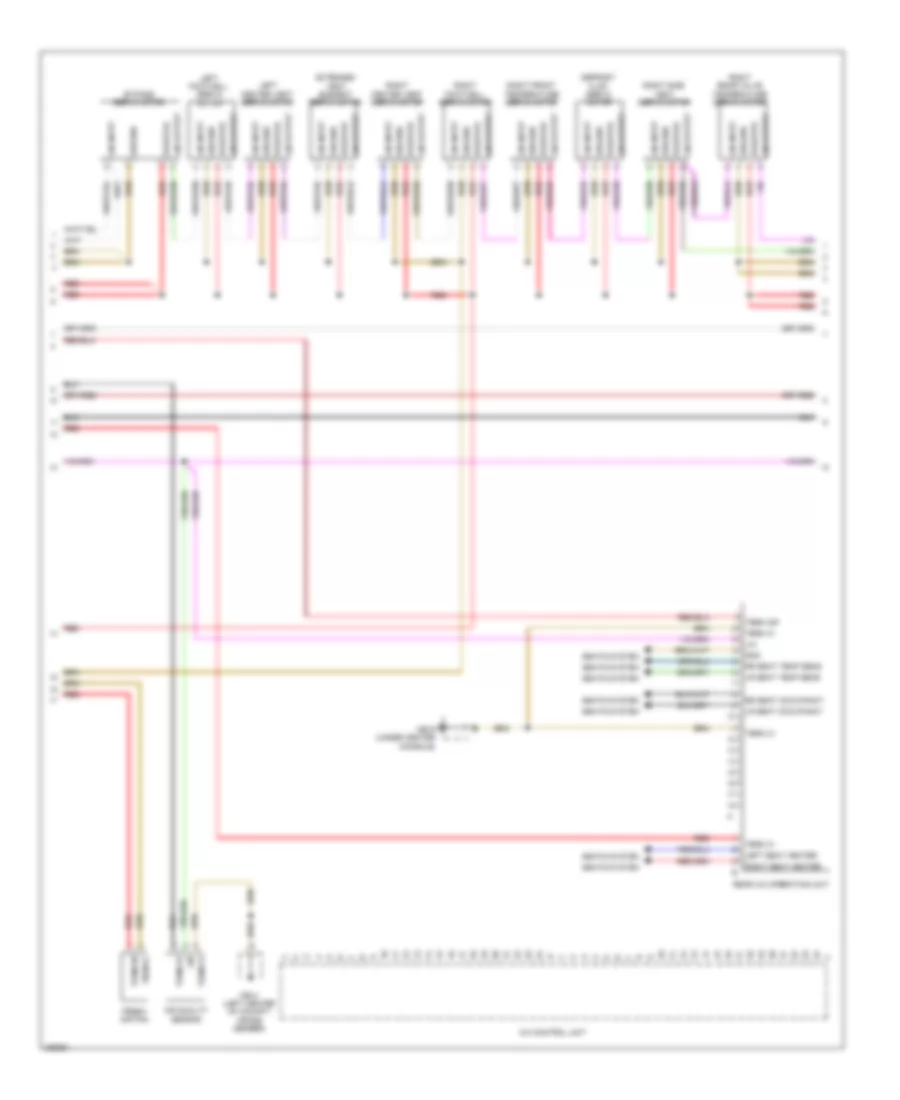
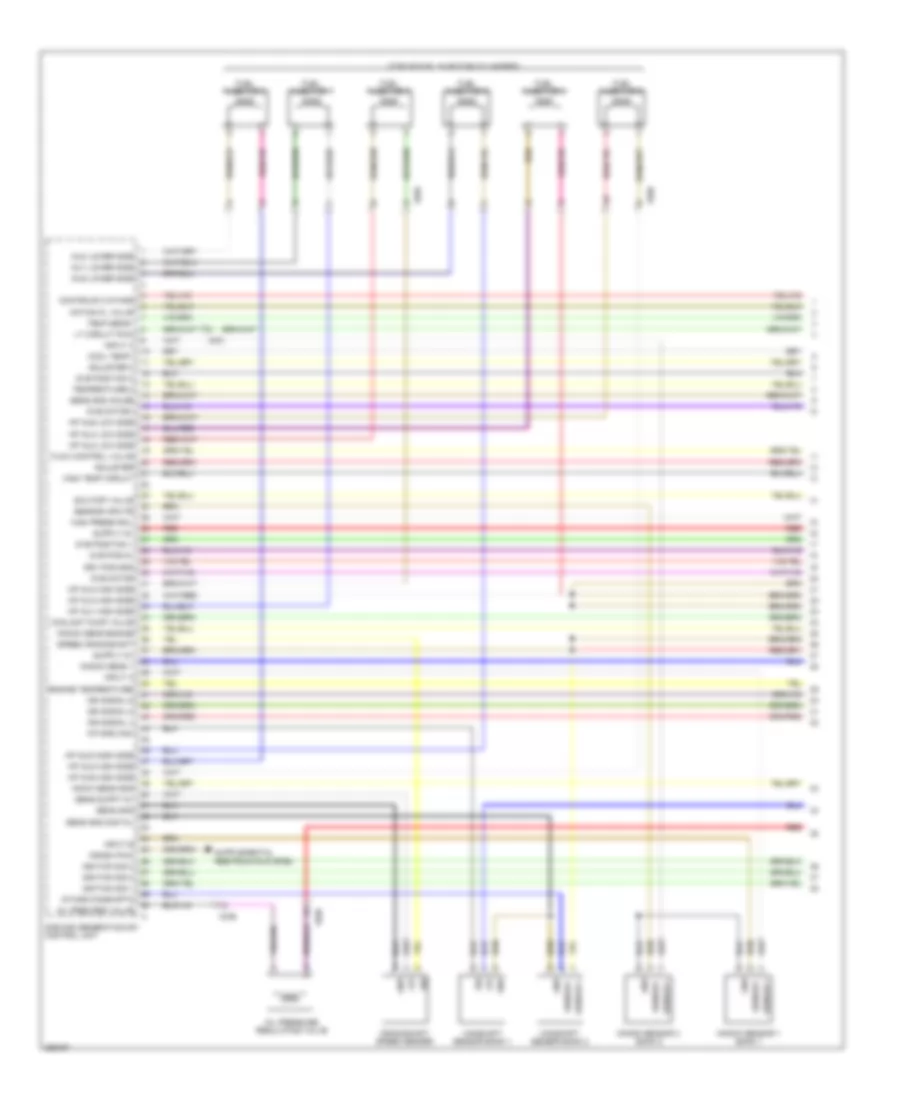
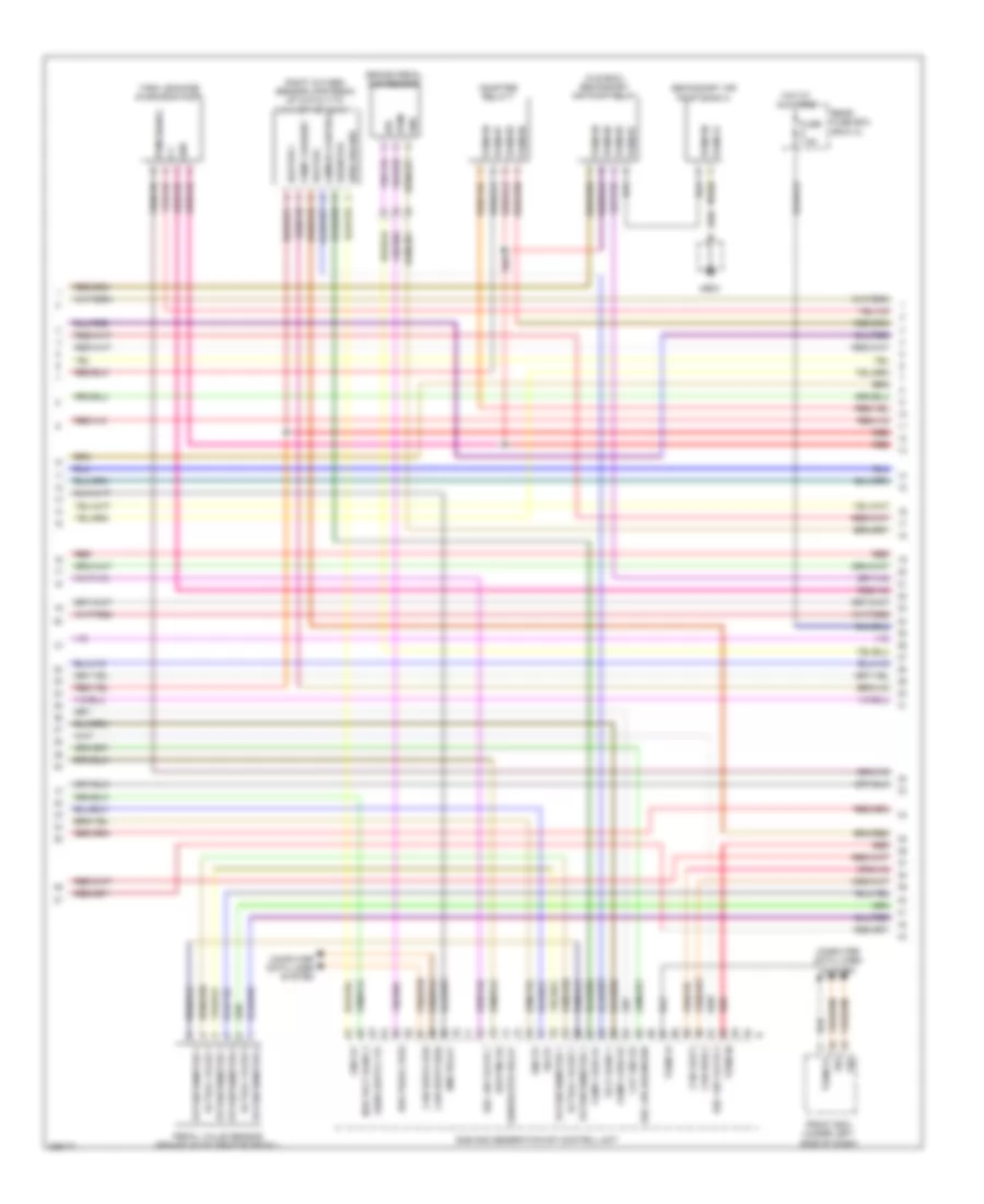
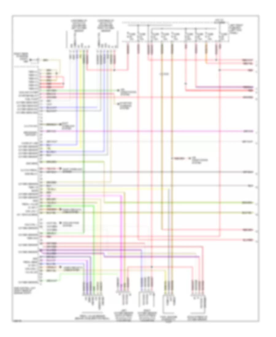
3.0L Hybrid, Engine Performance Wiring Diagram (3 of 7) for Porsche Panamera 4 2013
List of elements for 3.0L Hybrid, Engine Performance Wiring Diagram (3 of 7) for Porsche Panamera 4 2013:
- (fuel filler neck) tank venting valve
- +5v
- Boost pressure sensor
- Boost pressure sensor 2
- Dme relay 1
- Engine compartment temperature sensor
- Flow control valve
- Gnd
- Lkb sensor flap valve 1
- Lkb sensor flap valve 2
- Main water pump valve
- Ntc
- Positive
- Rail pressure sensor
- Red
- Secondary air valve 1
- Secondary air valve 2
- Shutoff valve
- Sig
- Signal
- Temp 87
- Transmission control module
- Transmission oil shut off valve
- Vcc
- Water valve 3e machine
- X031
- X032
- X035
- X036
- X037
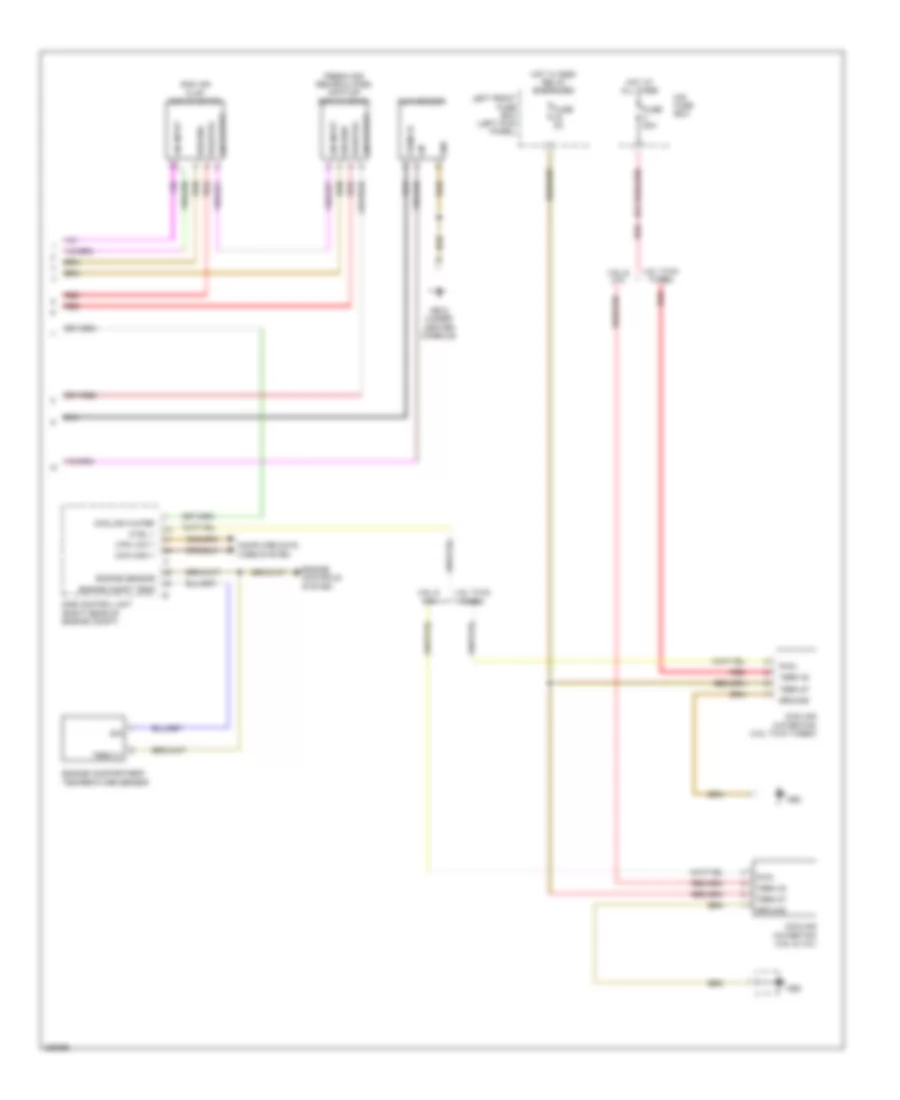
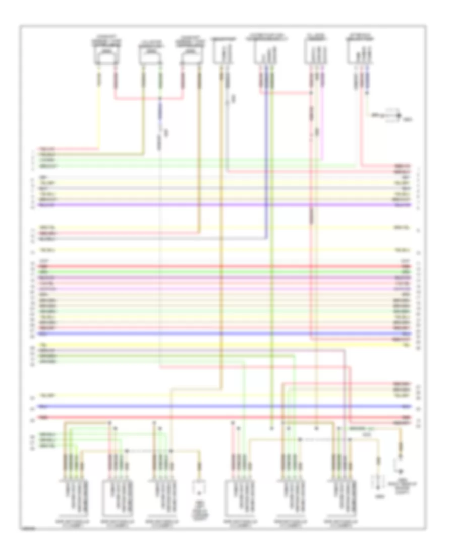
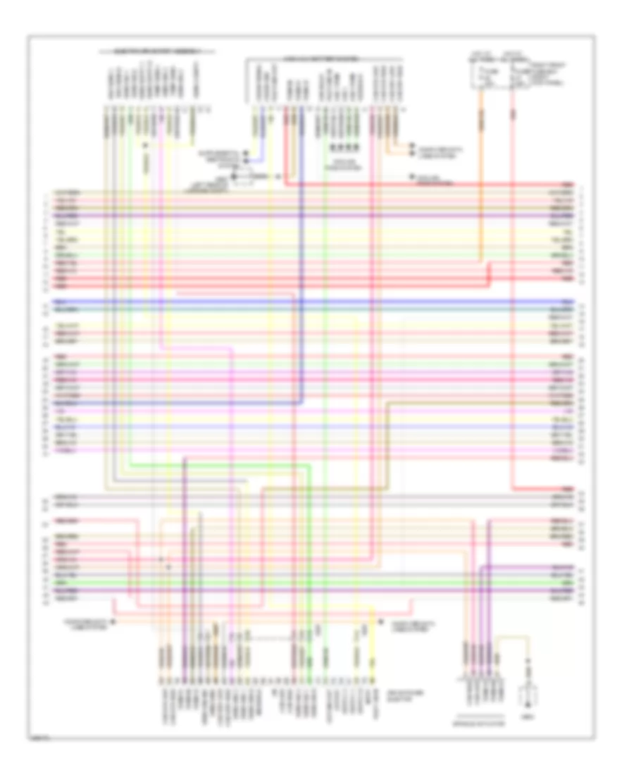
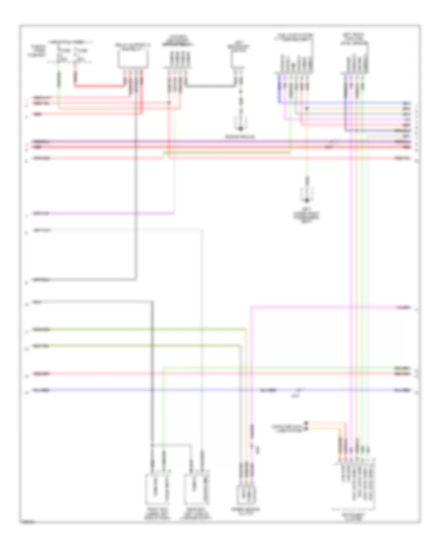
3.0L Hybrid, Engine Performance Wiring Diagram (4 of 7) for Porsche Panamera 4 2013
List of elements for 3.0L Hybrid, Engine Performance Wiring Diagram (4 of 7) for Porsche Panamera 4 2013:
- +5v
- A/c compressor valve bypass compressor
- Actual value 1
- Actual value 2
- Converter bank 2
- Coolant return temperature sensor
- Coolant temperature sensor
- Dc motor+
- Dc motor-
- Fuel-low pressure sensor
- Fuse 40a
- Fuse 60a
- Gnd
- Ground
- Heater +
- Heater -
- Hot at all times
- Intake manifold pressure sensor
- Left oxygen sensor downstream of catalytic converter bank 1
- Motor (-)
- Motor+
- Ntc
- Oil presser & temperature sensor
- Oxygen sensor upsyem of catalytic
- Plenum panel fuse box
- Pump current
- Red
- Rf+
- Right oxygen sensor downstream of catalytic converter bank 1
- Secondary air pressure sensor
- Sens gnd
- Sens sig
- Sens volt +
- Sensor+
- Sensor-
- Sig
- Signal
- Signal-
- Sns volt-
- Term 31
- Throttle valve (intake manifold)
- X031
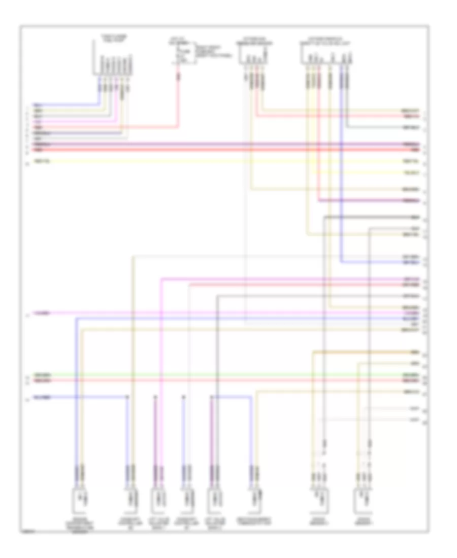
3.0L Hybrid, Engine Performance Wiring Diagram (5 of 7) for Porsche Panamera 4 2013
List of elements for 3.0L Hybrid, Engine Performance Wiring Diagram (5 of 7) for Porsche Panamera 4 2013:
- (in e box) secondary air pump relay
- (ipn) ground
- 5 v
- Actual value 1
- Actual value 2
- Adapter relay 7
- Brake pedal distsensor
- Brk pedal posi
- Can drive high
- Can drive low
- Can high 2
- Can low 2
- Cat gnd b2
- Comp curr b1
- Comp curr b2
- Computer data lines system
- Dme 2nd generation dfi control unit
- Dme relay
- Front bcm (under left side of dash)
- Fuse 7.5a
- Generator relay
- Gnd
- Gnd b1
- Heater +
- Heater -
- Heating b2
- Hot at all times
- Lambda control
- Mb03
- Ner volt bank 2
- Pedal value sensor (behind accelerator pedal)
- Potentiometer 1
- Potentiometer 2
- Pump current
- Pwm
- Pwm signal
- Rear fuse box (row c)
- Red
- Resistor
- Right oxygen sensor upstream of catalytic converter bank 1
- Sec air diagnosis
- Sec air valve 1
- Sec air valve 2
- Secondary air pump bank 2
- Sig
- Sig b1
- Tank leakage diagnosis pump
- Term 15
- Term 30
- Term 31
- Term 85
- Term 86
- Term 87
- Volt bank 1
3.0L Hybrid, Engine Performance Wiring Diagram (6 of 7) for Porsche Panamera 4 2013
List of elements for 3.0L Hybrid, Engine Performance Wiring Diagram (6 of 7) for Porsche Panamera 4 2013:
- Brk sens 0
- Brk sens 1
- Can driv high
- Can driv low
- Can drv high
- Can drv low
- Can high
- Can hyb high
- Can hyb low
- Can low
- Computer data lines system
- Cooling fans system
- Crash gnd
- Crash signal
- Drive power elector
- E-machine
- Electric drive part assembly
- Em shield
- Fan 1
- Fan 1 pwm
- Fan 2 pwm
- Fan relay
- Feedback
- Fuse 25a
- Fuse 30a
- High-volt battery system
- Hot at all times
- Input
- Lin
- Mb03
- Mb27 (left rear of luggage compt)
- Outline out
- Output
- Pilot lin in
- Pilotline in
- Pilotline out
- Red
- Right front fuse box (right kick panel)
- Sens 2 suppy
- Sens e-m gnd
- Sens gnd 0
- Sens gnd 1
- Sens gnd 2
- Sens sig 0
- Sens sig 1
- Sens sig 2
- Sens suppy 0
- Sens suppy 1
- Spindle actuator
- System
- Temp sens +
- Temp sens -
- Term 15
- Term 30
- Term 31
- X037
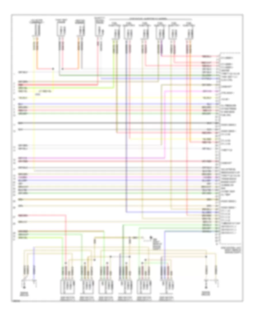
3.0L Hybrid, Engine Performance Wiring Diagram (7 of 7) for Porsche Panamera 4 2013
List of elements for 3.0L Hybrid, Engine Performance Wiring Diagram (7 of 7) for Porsche Panamera 4 2013:
- (right rear of engine compt) mb08
- 5v potentiometer 2
- Actual value 2
- Boost press sens 1
- Boost pump relay
- Brake vacuum sensor
- Can high
- Can low
- Changeover valve
- Charge motion flap
- Chrge-air temp 2
- Compressor
- Computer data lines system
- Cooling fans system
- Coolnent temp sens
- Ctrl unit fuel pump
- Dme 2nd generation dfi control unit
- Dmtl pump
- Dnstrof cat gnd b2
- Dnstrof cat sig b2
- Fuel low pressure
- Fuel pump system control unit
- Fuse 10a
- Fuse 15a
- Fuse 20a
- Fuse 30a
- Fuse 5a
- Fuse 7.5a
- Gnd
- Heater dmtl
- Heating b1
- Hot at all times
- Instrument cluster
- Left front fuse box (left kick panel)
- Left front trunk fuel level sensor
- Main fuse box (center front of engine compt)
- Mb17 (under front passenger's seat)
- Midi fuse 100a
- O2 sens
- O2 sens beh cat
- Oil press switch 1
- Oil press switch 2
- Oil pressure switch
- P/n
- Pedal value sensor
- Phase u
- Phase v
- Phase w
- Position 1
- Pump curr b1
- Pump curr b2
- Pwm
- Radiator fan 1 pwm
- Red
- Sec air pump relay
- Sender 1
- Sender 2
- Sender 3
- Sens gnd
- Sens gnd analogue
- Sensor
- Sensor 1
- Sensor 2
- Sensor 3
- Sensor gnd digital
- Sig
- Starting/charging system
- Tank flange fuel pump
- Term 31
- Term 50
- Term 87
- Transmissions system
- Water valve
- X031
- X032
- X036
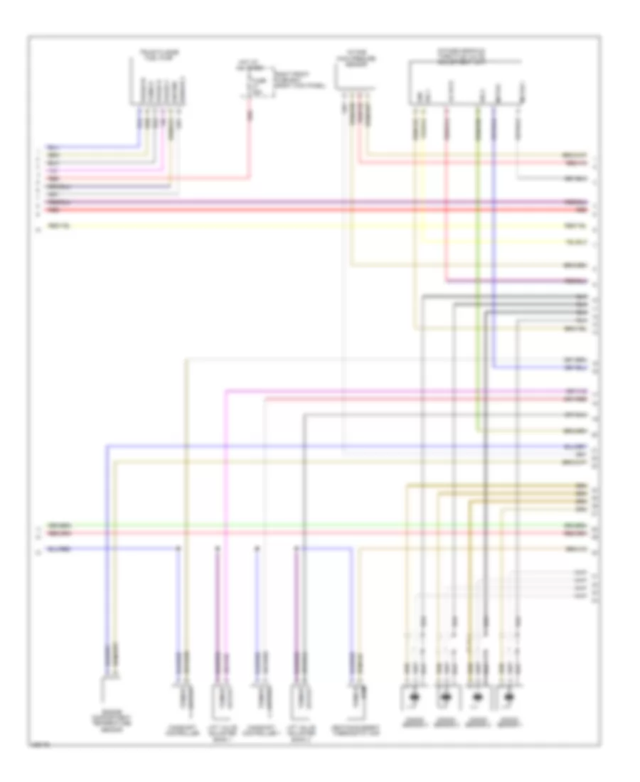
3.6L
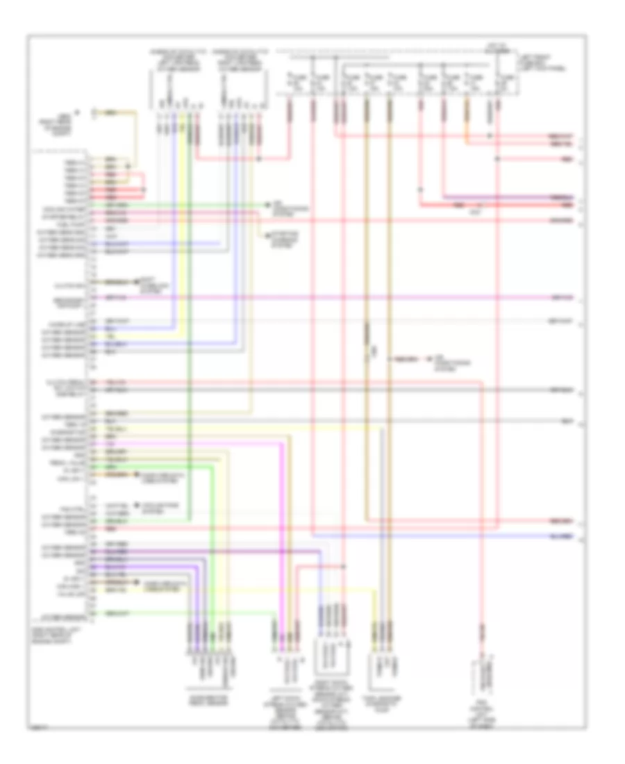
3.6L, Engine Performance Wiring Diagram (1 of 5) for Porsche Panamera 4 2013
List of elements for 3.6L, Engine Performance Wiring Diagram (1 of 5) for Porsche Panamera 4 2013:
- (right rear of engine compt) mb8
- (upstream of catalytic converter) left oxygen sensor
- (upstream of catalytic converter) right oxygen sensor
- +5v
- +5v vehicle sens
- 5v sply
- Air conditioning system
- Ape
- Bidir
- Can high 1
- Can low 1
- Clutch pedal
- Clutch sw
- Computer data lines system
- Cooling fans system
- Cooling water
- Dme control unit (right rear of engine compt)
- Dme relay
- Down stream of oxygen sensor
- Fan ctrl 1
- Fuel pump
- Fuse 10a
- Fuse 15a
- Fuse 20a
- Fuse 5a
- Fuse 7.5a
- Gnd
- Gnd sens
- Ground
- Hot at all times
- Ipn
- Lambda ctrl
- Left front fuse box (left kick panel)
- Left oxygen sensor (down stream of catalytic converter)
- Out
- Oxygen sens gnd
- Oxygen sens sig
- Oxygen sensor
- Pedal sens
- Pedal value
- Pedal value sensor (behind accelerator pedal)
- Red
- Right oxygen sensor (down stream of catalytic converter)
- Secondary air pump 1
- Sens
- Sensor sig
- Shift interlock system
- Starter relay
- Starting/ charging system
- Tank leakage diagnostic pump
- Term 15
- Term 30a
- Term 31
- Term 87
- Valve ldp
- Voltage +
- Voltage -
- Wake-up line
- X032
3.6L, Engine Performance Wiring Diagram (2 of 5) for Porsche Panamera 4 2013
List of elements for 3.6L, Engine Performance Wiring Diagram (2 of 5) for Porsche Panamera 4 2013:
- (in e box) secondary air pump relay 1
- (relay support 2) dme relay 1
- Can high
- Can low
- Computer data lines system
- Crash input
- Engine ground
- Front bcm (under left side of dash)
- Fuel level sens
- Fuel level sens 1
- Fuel level sens 2
- Fuel level sens 3
- Fuel pump system control unit
- Fuse 40a
- Fuse 60a
- Ground
- Hot at all times
- Input
- Instrument cluster
- Left front tank fuel level sensor
- Left secondary air fan
- Mb17 (under front passenger's seat)
- Output
- Phase u
- Phase v
- Phase w
- Plenum panel fuse box
- Pwm
- Rear bcm (left side of luggage compt)
- Red
- Sensor 1
- Sensor 3
- Speed sensor clutch
- Term 15
- Term 15sv
- Term 30
- Term 31
- Term 85
- Term 86
- Term 87
- Wakeup dme
- X031
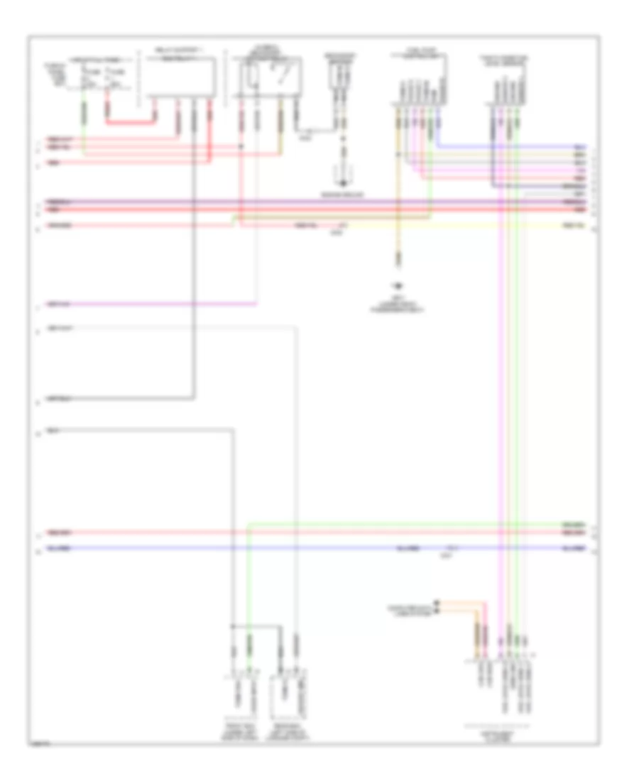
3.6L, Engine Performance Wiring Diagram (3 of 5) for Porsche Panamera 4 2013
List of elements for 3.6L, Engine Performance Wiring Diagram (3 of 5) for Porsche Panamera 4 2013:
- (intake manifold) throttle valve adj unit
- Camshaft controller b1
- Camshaft controller b2
- Engine compartment temperature sensor
- Fuse 25a
- Gnd
- Ground
- Heating element thermostat map
- Hot at all times
- Intake man pressure sensor
- Knock sensor 1
- Knock sensor 3
- Lift valve adjuster bank 1
- Lift valve adjuster bank 2
- Mtr +
- Mtr -
- Ntc
- Output
- Phase u
- Phase v
- Phase w
- Pwm
- Red
- Right front fuse box (right kick panel)
- Sensor 2
- Sig
- Sig +
- Sig 1
- Sig 2
- Tank flange fuel pump
- Term 31
- Term 87
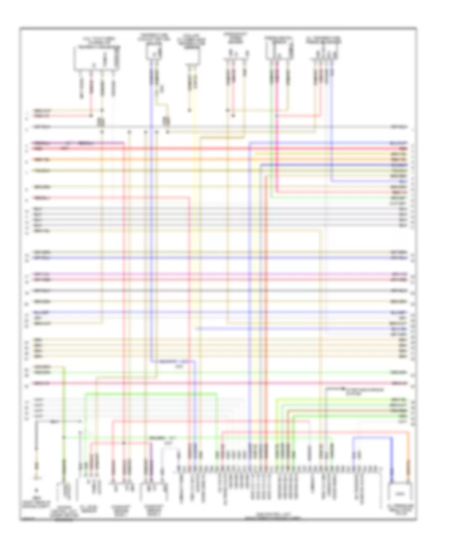
3.6L, Engine Performance Wiring Diagram (4 of 5) for Porsche Panamera 4 2013
List of elements for 3.6L, Engine Performance Wiring Diagram (4 of 5) for Porsche Panamera 4 2013:
- 12 v
- 3-5v
- 5v sply
- Air bag control unit (under center console)
- Camshaft
- Camshaft sens
- Coolant cylinder head temperature sensor
- Coolant return temperature sensor
- Crankshaft speed sensor
- Crash output
- Crash signal
- Cyl 3
- Cyl 5
- Dme control unit (right rear of engine compt)
- Generator
- Gnd
- Ground
- Ignition cyl 2
- Ignition cyl 5
- Ignition cyl 6
- Left side camshaft sensor bank 1
- Left side camshaft sensor bank 2
- Low
- Mb8 (right rear of engine compt)
- Nca
- Ntl
- Oil level pulses sensor
- Oil press valve
- Oil pressure
- Oil pressure regulating valve
- Oil temperature & pressure sensor
- Oil valve
- Out
- Output
- Pwm
- Rail pressure sensor
- Red
- Sensor +
- Sensor -
- Shield
- Sig
- Starting/charging system
- Temp
- Term 31
- Term 87
- Thro vlv gnd
- Throttle valve
- X031
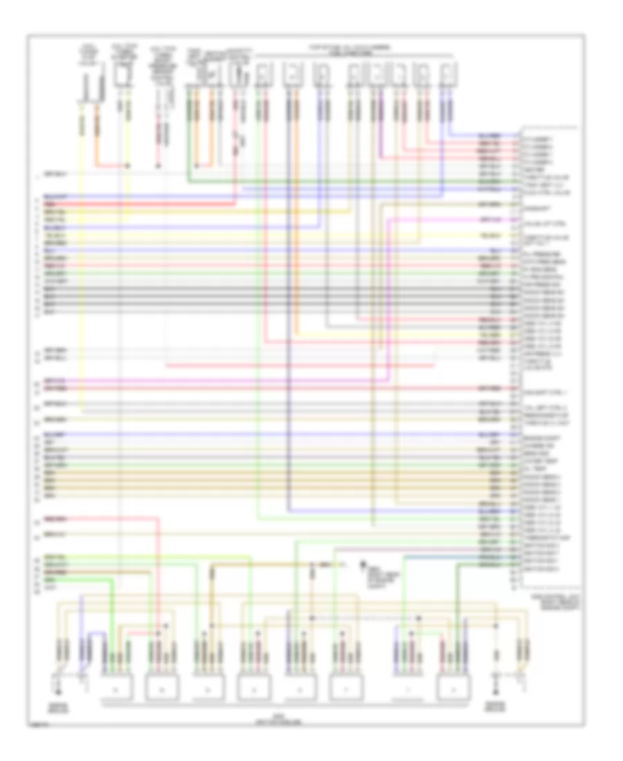
3.6L, Engine Performance Wiring Diagram (5 of 5) for Porsche Panamera 4 2013
List of elements for 3.6L, Engine Performance Wiring Diagram (5 of 5) for Porsche Panamera 4 2013:
- (top of fuel injector cylinders)
- 5v eng sens
- Actuation
- Adjuster b2
- Bar ignition module cyl 1
- Bar ignition module cyl 2
- Bar ignition module cyl 3
- Bar ignition module cyl 4
- Bar ignition module cyl 5
- Bar ignition module cyl 6
- Camshaft
- Charge air
- Ctrl bank 1
- Cyl 1 ls
- Cyl 2 hs
- Cyl 2 ls
- Cyl 4 ls
- Cyl 5 hs
- Cyl 6 hs
- Cyl 6 ls
- Cylinder 1
- Cylinder 3
- Cylinder 4
- Dme control unit (right rear of engine compt)
- Engine compt
- Engine ground
- Flow ctrl
- Fuel injector 1
- Fuel injector 2
- Fuel injector 3
- Fuel injector 4
- Fuel injector 5
- Fuel injector 6
- Fuel rail
- Gnd
- Heater
- Heating element
- Ignition cyl 1
- Ignition cyl 3
- Ignition cyl 4
- Intake press
- Knock sens 1
- Knock sens 2
- Mb8 (right rear of engine compt)
- Oil pressure
- Oil temp
- Positive
- Pwm
- Quantity control valve
- Red
- Resonance flap
- Tank vent valve
- Tank vent vlv
- Term 15
- Term 31
- Term 87
- Thermostat map
- Throttle
- Throttle valve
- Transmission
- Valve 1
- Valve for tuning flap 1
- Water temp
- X032
4.8L
4.8L, Engine Performance Wiring Diagram (1 of 5) for Porsche Panamera 4 2013
List of elements for 4.8L, Engine Performance Wiring Diagram (1 of 5) for Porsche Panamera 4 2013:
- (ahead of catalytic converter) left upstream oxygen sensor
- (ahead of catalytic converter) right upstream oxygen sensor
- +5v
- 5v sply
- Accelerator pedal sensor
- Air conditioning system
- Ape
- Can high 1
- Can low 1
- Clutch pedal
- Clutch sw
- Computer data lines system
- Cooling fans system
- Cooling water
- Diagnostics
- Dme control unit (right rear of engine compt)
- Dme relay
- Fan ctrl
- Fuel pump
- Fuse 10a
- Fuse 15a
- Fuse 20a
- Fuse 5a
- Fuse 7.5a
- Gnd
- Ground
- Hot at all times
- Ipn
- Lambda ctrl
- Left down stream oxygen sensor (behind catalytic converter)
- Left front fuse box (left kick panel)
- Lock sig
- Mb08 (right rear of engine compt)
- Out
- Oxygen sens gnd
- Oxygen sens sig
- Oxygen sensor
- Pdk control unit (left side of dash)
- Pedal value
- Pin start
- Red
- Right down stream oxygen sensor (a/t) down stream oxygen sensor (m/t) (behind catalytic converter)
- Secondary air pump 1
- Sens sig
- Sensor sig
- Shift interlock system
- Sig
- Starter relay
- Starting/ charging system
- Sw low m/c
- Tank leakage diagnostic pump
- Term 15
- Term 30
- Term 31
- Term 87
- Valve ldp
- Voltage +
- Voltage -
- Wake-up line
- X031
- X302
4.8L, Engine Performance Wiring Diagram (2 of 5) for Porsche Panamera 4 2013
List of elements for 4.8L, Engine Performance Wiring Diagram (2 of 5) for Porsche Panamera 4 2013:
- (in ebox) secondary air pump relay
- Can high
- Can low
- Computer data lines system
- Crash input
- Dme relay 1
- Engine ground
- Front bcm (under left side of dash)
- Fuel level sens 1
- Fuel level sens 2
- Fuel level sens 3
- Fuel pump control unit
- Fuse 40a
- Fuse 60a
- Ground
- Hot at all times
- Instrument cluster
- Mb17 (under front passenger's seat)
- Nca
- Phase u
- Phase v
- Phase w
- Plenum panel fuse box
- Pwm
- Rear bcm (left side of luggage compt)
- Red
- Relay support 1
- Secondary air pump
- Sender 1
- Sender 3
- Sens gnd
- Tank flange fuel level sensor
- Term 15
- Term 15sv
- Term 30
- Term 30 nca
- Term 31
- Wakeup dme
- X031
- X032
4.8L, Engine Performance Wiring Diagram (3 of 5) for Porsche Panamera 4 2013
List of elements for 4.8L, Engine Performance Wiring Diagram (3 of 5) for Porsche Panamera 4 2013:
- (intake manifold) throttle valve adjustment unit
- -5v poti
- Camshaft controller
- Camshaft controller 1
- Engine compartment temperature sensor
- Fuse 25a
- Gnd
- Ground
- Heating element thermostat map
- Hot at all times
- Intake main presure sensor
- Knock sensor 1
- Knock sensor 2
- Knock sensor 3
- Knock sensor 4
- Lift valve adjuster bank 1
- Lift valve adjuster bank 2
- Motor +
- Motor -
- Output
- Phase u
- Phase v
- Phase w
- Pwm
- Red
- Right front fuse box (right kick panel)
- Sender 2
- Sig 1
- Sig 2
- Term 31
- Term 87
- Trunk flange fuel pump
4.8L, Engine Performance Wiring Diagram (4 of 5) for Porsche Panamera 4 2013
List of elements for 4.8L, Engine Performance Wiring Diagram (4 of 5) for Porsche Panamera 4 2013:
- (4.8l twin turbo) charge air temperature sensor
- (not used)
- 12v
- 5v sply
- Air bag control unit (under center console)
- Camshaft
- Camshaft sens
- Camshaft sensor bank 1
- Camshaft sensor bank 2
- Coolant cylinder head temperature sensor
- Crankshaft speed sender
- Crash output
- Crash signal
- Diverter valve
- Dme control unit (right rear of engine compt)
- Generator
- Gnd
- Ground
- Hdev zyl 2 ls
- Hdev zyl 4 ls
- Hdev zyl 7 ls
- Hdev zyl 8 ls
- Ignition sig 2
- Ignition sig 5
- Ignition sig 6
- Ignition sig 8
- Low
- Mb08 (right rear of engine compt)
- Ntc
- Oil level sensor
- Oil press valve
- Oil pressure
- Oil pressure regulating valve
- Oil temperature/ pressure sensor
- Oil valve
- Out
- Output
- Press sig
- Pressure rail sensor
- Radiator
- Red
- Sig
- Speed sens po
- Starting/charging system
- Temperature coolant return sensor
- Term 31
- Thro vlv gnd
- Thro vlv sply
- X031
4.8L, Engine Performance Wiring Diagram (5 of 5) for Porsche Panamera 4 2013
List of elements for 4.8L, Engine Performance Wiring Diagram (5 of 5) for Porsche Panamera 4 2013:
- (4.8l twin turbo) boost pressure sensor control valve
- (4.8l twin turbo) diverter valve
- (4.8l) tuning flap valve 1
- (top of fuel inj 1-6 cylinders) fuel injectors
- 5v eng sens
- Air press sig
- Air press vlv
- Bar ignition modules
- Cam shft ctrl 1
- Camshaft
- Charge air
- Cylinder 1
- Cylinder 2
- Cylinder 3
- Cylinder 7
- Dme control unit (right rear of engine compt)
- Engine compt
- Engine ground
- Flow ctrl valve
- Hdev cyl 1 ls
- Hdev cyl 3 ls
- Hdev cyl 4 hs
- Hdev cyl 5 hs
- Hdev cyl 5 ls
- Hdev cyl 6 hs
- Hdev cyl 6 ls
- Hdev cyl 8 hs
- Heater
- Heating element
- Hi prs sns rail
- Ignition sig 1
- Ignition sig 3
- Ignition sig 4
- Ignition sig 7
- Intk pres sens
- Knock sens 1
- Knock sens 2
- Knock sens 3
- Knock sens 4
- Knock sens sh
- Mb08 (right rear of engine compt)
- Oil pressure
- Oil temp
- Positive
- Pwn
- Quantity control valve
- Red
- Resonance flap
- Send gnd
- Tank vent valve
- Tank vent vlv
- Term87
- Thermostat map
- Throtle vlv act
- Throttle valve
- Throttle valve act val 1
- Throttle valve mtr
- Val left ctrl 2
- Valve lift ctrl
- Water temp
- X031
4.8L TWIN TURBO
4.8L Twin Turbo, Engine Performance Wiring Diagram (1 of 5) for Porsche Panamera 4 2013
List of elements for 4.8L Twin Turbo, Engine Performance Wiring Diagram (1 of 5) for Porsche Panamera 4 2013:
- (ahead of catalytic converter) left upstream oxygen sensor
- (ahead of catalytic converter) right upstream oxygen sensor
- +5v
- 5v sply
- Accelerator pedal sensor
- Air conditioning system
- Ape
- Can high 1
- Can low 1
- Clutch pedal
- Clutch sw
- Computer data lines system
- Cooling fans system
- Cooling water
- Diagnostics
- Dme control unit (right rear of engine compt)
- Dme relay
- Fan ctrl
- Fuel pump
- Fuse 10a
- Fuse 15a
- Fuse 20a
- Fuse 5a
- Fuse 7.5a
- Gnd
- Ground
- Hot at all times
- Ipn
- Lambda ctrl
- Left down stream oxygen sensor (behind catalytic converter)
- Left front fuse box (left kick panel)
- Lock sig
- Mb08 (right rear of engine compt)
- Out
- Oxygen sens gnd
- Oxygen sens sig
- Oxygen sensor
- Pdk control unit (left side of dash)
- Pedal value
- Pin start
- Red
- Right down stream oxygen sensor (a/t) down stream oxygen sensor (m/t) (behind catalytic converter)
- Secondary air pump 1
- Sens sig
- Sensor sig
- Shift interlock system
- Sig
- Starter relay
- Starting/ charging system
- Sw low m/c
- Tank leakage diagnostic pump
- Term 15
- Term 30
- Term 31
- Term 87
- Valve ldp
- Voltage +
- Voltage -
- Wake-up line
- X031
- X302
4.8L Twin Turbo, Engine Performance Wiring Diagram (2 of 5) for Porsche Panamera 4 2013
List of elements for 4.8L Twin Turbo, Engine Performance Wiring Diagram (2 of 5) for Porsche Panamera 4 2013:
- (in ebox) secondary air pump relay
- Can high
- Can low
- Computer data lines system
- Crash input
- Dme relay 1
- Engine ground
- Front bcm (under left side of dash)
- Fuel level sens 1
- Fuel level sens 2
- Fuel level sens 3
- Fuel pump control unit
- Fuse 40a
- Fuse 60a
- Ground
- Hot at all times
- Instrument cluster
- Mb17 (under front passenger's seat)
- Nca
- Phase u
- Phase v
- Phase w
- Plenum panel fuse box
- Pwm
- Rear bcm (left side of luggage compt)
- Red
- Relay support 1
- Secondary air pump
- Sender 1
- Sender 3
- Sens gnd
- Tank flange fuel level sensor
- Term 15
- Term 15sv
- Term 30
- Term 30 nca
- Term 31
- Wakeup dme
- X031
- X032
4.8L Twin Turbo, Engine Performance Wiring Diagram (3 of 5) for Porsche Panamera 4 2013
List of elements for 4.8L Twin Turbo, Engine Performance Wiring Diagram (3 of 5) for Porsche Panamera 4 2013:
- (intake manifold) throttle valve adjustment unit
- -5v poti
- Camshaft controller
- Camshaft controller 1
- Engine compartment temperature sensor
- Fuse 25a
- Gnd
- Ground
- Heating element thermostat map
- Hot at all times
- Intake main presure sensor
- Knock sensor 1
- Knock sensor 2
- Knock sensor 3
- Knock sensor 4
- Lift valve adjuster bank 1
- Lift valve adjuster bank 2
- Motor +
- Motor -
- Output
- Phase u
- Phase v
- Phase w
- Pwm
- Red
- Right front fuse box (right kick panel)
- Sender 2
- Sig 1
- Sig 2
- Term 31
- Term 87
- Trunk flange fuel pump
4.8L Twin Turbo, Engine Performance Wiring Diagram (4 of 5) for Porsche Panamera 4 2013
List of elements for 4.8L Twin Turbo, Engine Performance Wiring Diagram (4 of 5) for Porsche Panamera 4 2013:
- (4.8l twin turbo) charge air temperature sensor
- (not used)
- 12v
- 5v sply
- Air bag control unit (under center console)
- Camshaft
- Camshaft sens
- Camshaft sensor bank 1
- Camshaft sensor bank 2
- Coolant cylinder head temperature sensor
- Crankshaft speed sender
- Crash output
- Crash signal
- Diverter valve
- Dme control unit (right rear of engine compt)
- Generator
- Gnd
- Ground
- Hdev zyl 2 ls
- Hdev zyl 4 ls
- Hdev zyl 7 ls
- Hdev zyl 8 ls
- Ignition sig 2
- Ignition sig 5
- Ignition sig 6
- Ignition sig 8
- Low
- Mb08 (right rear of engine compt)
- Ntc
- Oil level sensor
- Oil press valve
- Oil pressure
- Oil pressure regulating valve
- Oil temperature/ pressure sensor
- Oil valve
- Out
- Output
- Press sig
- Pressure rail sensor
- Radiator
- Red
- Sig
- Speed sens po
- Starting/charging system
- Temperature coolant return sensor
- Term 31
- Thro vlv gnd
- Thro vlv sply
- X031
4.8L Twin Turbo, Engine Performance Wiring Diagram (5 of 5) for Porsche Panamera 4 2013
List of elements for 4.8L Twin Turbo, Engine Performance Wiring Diagram (5 of 5) for Porsche Panamera 4 2013:
- (4.8l twin turbo) boost pressure sensor control valve
- (4.8l twin turbo) diverter valve
- (4.8l) tuning flap valve 1
- (top of fuel inj 1-6 cylinders) fuel injectors
- 5v eng sens
- Air press sig
- Air press vlv
- Bar ignition modules
- Cam shft ctrl 1
- Camshaft
- Charge air
- Cylinder 1
- Cylinder 2
- Cylinder 3
- Cylinder 7
- Dme control unit (right rear of engine compt)
- Engine compt
- Engine ground
- Flow ctrl valve
- Hdev cyl 1 ls
- Hdev cyl 3 ls
- Hdev cyl 4 hs
- Hdev cyl 5 hs
- Hdev cyl 5 ls
- Hdev cyl 6 hs
- Hdev cyl 6 ls
- Hdev cyl 8 hs
- Heater
- Heating element
- Hi prs sns rail
- Ignition sig 1
- Ignition sig 3
- Ignition sig 4
- Ignition sig 7
- Intk pres sens
- Knock sens 1
- Knock sens 2
- Knock sens 3
- Knock sens 4
- Knock sens sh
- Mb08 (right rear of engine compt)
- Oil pressure
- Oil temp
- Positive
- Pwn
- Quantity control valve
- Red
- Resonance flap
- Send gnd
- Tank vent valve
- Tank vent vlv
- Term87
- Thermostat map
- Throtle vlv act
- Throttle valve
- Throttle valve act val 1
- Throttle valve mtr
- Val left ctrl 2
- Valve lift ctrl
- Water temp
- X031
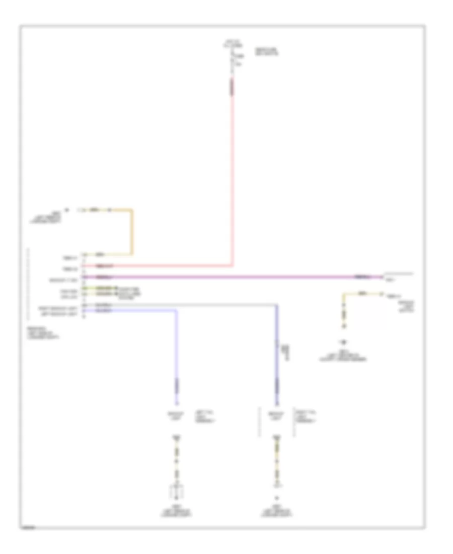
EXTERIOR LIGHTS
Backup Lamps Wiring Diagram for Porsche Panamera 4 2013
List of elements for Backup Lamps Wiring Diagram for Porsche Panamera 4 2013:
- (hybrid) x902
- Backup light
- Backup light switch
- Backup lt sw
- Can high
- Can low
- Computer data lines system
- Fuse 15a
- Gnd
- Hot at all times
- Left backup light
- Left tail light assembly
- Mb14 (left center of cockpit cross member)
- Mb27 (left rear of luggage compt)
- Rear bcm (left side of luggage compt)
- Rear fuse box (row b)
- Right backup light
- Right tail light assembly
- Sig +
- Term 30
- Term 31
Exterior Lamps Wiring Diagram (1 of 2) for Porsche Panamera 4 2013
List of elements for Exterior Lamps Wiring Diagram (1 of 2) for Porsche Panamera 4 2013:
- Backup light
- Can high
- Can low
- Computer data lines system
- Except hybrid
- Fuse 15a
- Gnd
- High-mounted stop light
- Hot at all times
- Hybrid
- Left backup light
- Left number plate light
- Left side turn signal
- Left stop light
- Left tail light assembly
- Left taillight
- Left turn sig
- License plate light
- Lr fog light
- Mb03
- Mb27 (left rear of luggage compt)
- Mb29 (top of right "c" pillar)
- Rear bcm (left side of luggage compt)
- Rear fog light
- Rear fuse box (row b)
- Right backup light
- Right number plate light
- Right stop light
- Right tail light assembly
- Right taillight
- Right turn sig
- Rr fog light
- Stop light
- Taillight
- Term 30
- Term 31
- Trailer tow circuit
- X241
- X901
- X902
Exterior Lamps Wiring Diagram (2 of 2) for Porsche Panamera 4 2013
List of elements for Exterior Lamps Wiring Diagram (2 of 2) for Porsche Panamera 4 2013:
- (info not available)
- A/c control unit
- Capacitor ground
- Computer data lines system
- Front bcm (under left side of dash)
- High mounted stop light (except hybrid)
- High mounted stop light (hybrid)
- Left front side marker light
- Lf side direction ind
- Lf side marker light
- Lf turn sig
- Light switch hazard warning
- Lin
- Lr turn sig
- Mb04 (right front of engine compt)
- Mb09 (left "a" pillar)
- Mb11 (right "a" pillar)
- Mb27 (left rear of luggage compt)
- Rf side direction ind
- Rf side marker light
- Rf turn sig
- Right front side marker light
- Right side turn signal
- Rr turn sig
- Suppression capacitor
- Switching steering column module
- Turn signal switch
- Warning light button
- X019
- X109
- X240
- X752
- X753
Trailer Tow Wiring Diagram for Porsche Panamera 4 2013
List of elements for Trailer Tow Wiring Diagram for Porsche Panamera 4 2013:
- Backup light
- Can high
- Can low
- Computer data lines system
- Extend
- Front bcm (under left side of dash)
- Fuse 10a
- Fuse 15a
- Fuse 30a
- Gnd
- Hall sens +
- Hall sens -
- Hall sens sig
- Hot at all times
- Hot w/ kl 15a relay energized
- Hybrid
- In function display
- Left taillight
- Left term 30
- Left turn sig
- Locating light
- Locking bolt 1
- Locking bolt 2
- Locking bolt hall sens -
- Mb26 (right rear of luggage compt)
- Out function display
- Rear fog light
- Rear fuse box (row a)
- Red
- Retract
- Right front fuse box
- Right stop light
- Right taillight
- Right term 30
- Right turn sig
- Sig
- Stop light
- Stop light sw low
- Swivel in function dsply
- Swivel motor +
- Swivel motor -
- Swivel off sig
- Swivel on sig
- Swivel out function dsply
- Term 15
- Term 30 motor
- Term 30f
- Term 31
- Term 31 button
- Term 31 motor
- Term 58 d
- Trailer hitch control unit (right side of luggage compt)
- Trailer hitch locking bolt switch
- Trailer hitch pivot motor
- Trailer hitch switch
- Trailer socket
- X901
- X902
- X903
GROUND DISTRIBUTION
Ground Distribution Wiring Diagram (1 of 6) for Porsche Panamera 4 2013
List of elements for Ground Distribution Wiring Diagram (1 of 6) for Porsche Panamera 4 2013:
- (halogen) right headlight
- (not used)
- Bar ignition module cylinder 1
- Bar ignition module cylinder 2
- Bar ignition module cylinder 3
- Bar ignition module cylinder 4
- Bar ignition module cylinder 5
- Bar ignition module cylinder 6
- Clutch pedal sensor
- Condenser block circuit
- Condensor ground
- Cool box preparation
- Diagnostic plug socket
- Driver knee air bag
- Driver's door center lock safe led
- Epb control unit
- Filler neck ground point
- Ground ignition coil 1 (hybrid)
- Ground ignition coil 5 (hybrid)
- Iru deactivation button
- Left front door sill light
- Left front footwell light
- Left side marker light
- Mb04 (right front of engine compt)
- Mb06 (right rear of engine compt)
- Mb22 (top of right "c" pillar)
- Mb23 (right rear quarterpanel)
- Mb9 (left "a" pillar)
- Nca
- Outer door handle driver electronic
- Parking heater control unit
- Passenger knee air bag
- Pdcc steering level sensor
- Psm control unit
- Rear passenger side thorax air bag
- Refrigerant pressure sensor
- Right rear seat adjustment control unit
- Right rear side bolster heating element
- Right side turn signal
- Roof console
- Sliding roof control unit
- To mb15 (diagram 2 of 6)
- X043
- X109
- X110
- X111
- X403
Ground Distribution Wiring Diagram (2 of 6) for Porsche Panamera 4 2013
List of elements for Ground Distribution Wiring Diagram (2 of 6) for Porsche Panamera 4 2013:
- (info not available)
- (information not available) interior mirror
- Air quality sensor
- Alarm siren
- Backup light switch
- Bar ignition module cylinder 1
- Bar ignition module cylinder 2
- Bar ignition module cylinder 3
- Bar ignition module cylinder 4
- Bar ignition module cylinder 5
- Bar ignition module cylinder 6
- Bar ignition module cylinder 7
- Bar ignition module cylinder 8
- Can distributor
- Cluster sensor
- Driver fan blower regulator
- Driver knee air bag ignition pill
- Driver's active lid
- Engine ground (3.6l)
- Engine ground (4.8l)
- From mb9 (diagram 1 of 6)
- Front bcm
- Front center console socket
- Front passenger door central lock safe led
- Front passenger door lock
- Glove box plug socket
- Glove box switch
- Headlight washer fluid pump
- Left center cockpit air vent lighting
- Left side cockpit air vent lighting
- Mb11 (right "a" pillar)
- Mb14 (left side of support frame)
- Mb15 (left side of support frame)
- Nca
- Passenger knee air bag ignition pill
- Passenger's active lid
- Passenger's door control unit
- Pdk control unit
- Rain sensor
- Right center cockpit air vent lighting
- Right cockpit air vent lighting
- Right front door sill lighting
- Right front footwell light
- Right front outer door handle electronics
- Right front side marker light
- Secondary air pump
- Steering column adjustment
- Steering column switch module
- Theft protection alarm horn
- X017
- X019
- X120
- X121
- X210
- X320
- X423
- X820
Ground Distribution Wiring Diagram (3 of 6) for Porsche Panamera 4 2013
List of elements for Ground Distribution Wiring Diagram (3 of 6) for Porsche Panamera 4 2013:
- (except hybrid) high mounted stop light
- (except hybrid) transmission oil pump driver
- (hybrid) suppression capacitor
- (hybrid) transmission oil pump driver
- (info not available)
- (w/ memory) front passenger seat control unit
- Backup camera control unit
- Cushion heating element
- Driver's door ignition lock light
- Electronic ignition lock
- Front bcm
- Front passenger seat adjustment output control unit
- Front passenger seat footwell light
- Front rear seat entertainment
- Fuel metering pump
- Fuel pump control unit
- Fuel tank flange pump
- Heated backrest
- Left rear seat adjustment control unit
- Left rear side bolster heating element
- Left seat backrest ventilation
- Left seat cushion ventilation
- Left side backrest bolster heating
- Left side cushion bolsters
- Luggage compartment socket
- Mb13 (left side of support frame)
- Mb17 (under front passenger's seat)
- Mb21 (top of left "c" pillar)
- Mb25 (right rear of luggage compt)
- Nca
- Rear driver side thorax air bag
- Right ''b" pillar air vent lighting
- Right makeup mirror
- Right rear door control unit
- Right rear door lock
- Right rear door sill lighting
- Right rear elect- ronics outer door handle
- Right seat backrest ventilation
- Right seat cushion ventilation
- Right side backrest bolster heating
- Right side cushion bolsters
- Rotary light switch
- Steering column lock
- Subwoofer
- Television tuner
- To ground mb27 (diagram 6 of 6)
- Transmission control unit
- Two tone horn relay
- W/ bose
- W/ memory
- W/ passenger power seats
- W/o bose
- X141
- X170
- X172
- X173
- X175
- X240
- X533
- X534
Ground Distribution Wiring Diagram (4 of 6) for Porsche Panamera 4 2013
List of elements for Ground Distribution Wiring Diagram (4 of 6) for Porsche Panamera 4 2013:
- (4.8l) bar ignition module
- After-run coolant pump
- Air bag ground (w/ msw)
- Air conditioning compressor valve
- Bar ignition module
- Brake fluid sensor
- Centre heated spray jet
- Coolant level switch
- Cooling fan water 600w
- Cooling fan water 850w
- Cylinder 1
- Cylinder 2
- Cylinder 3
- Cylinder 4
- Cylinder 5
- Cylinder 6
- Cylinder 7
- Cylinder 8
- Dme control unit
- Driver's seat
- E-box steering wheel
- Electric a/c compressor
- Esd
- Except hybrid
- Front evaporator shut-off valve
- Front wiper motor
- Hybrid
- Left auxiliary headlight
- Left coolant level sensor circuit
- Left front heated spray jet
- Left headlight
- Left side turn signal
- Left tiptronic button
- Mb03
- Mb07 (left rear of engine compt)
- Mb08 (right rear of engine compt)
- Mb32 (hybrid) (left side of luggage compt)
- Oil level sensor
- Power steering pump
- Right front heated spray jet
- Right tiptronic button
- Secondary air pumpbank 2
- Shield
- Spindle actuator
- Starter
- Steering column switching module
- Water circulating pump relay
- X032
- X230
Ground Distribution Wiring Diagram (5 of 6) for Porsche Panamera 4 2013
List of elements for Ground Distribution Wiring Diagram (5 of 6) for Porsche Panamera 4 2013:
- (info not available)
- (w/ 838) rear center console plug socket 1
- (w/ 838) rear center console plug socket 2
- (w/ memory) driver's seat control unit
- (w/o 838) rear center console plug socket
- A (base)
- A (premium)
- A/c control unit
- Amplifier
- Cigar lighter center console
- Cushion heating element
- Driver's seat adjustment control unit
- Driver's seat footwell light
- Electronics outer door handle
- Heated backrest
- Instrument cluster
- Left b-pillar air vent lighting
- Left back- rest heating element
- Left rear center lighting air vent
- Left rear door control unit
- Left rear door lock
- Left rear door sill lighting
- Left rear lumbar support valve block
- Left rear seat back- rest vent motor
- Left rear seat cushion heating element
- Left rear seat cushion vent motor
- Left rear seat entertain- ment
- Left seat backrest ventilation
- Left seat cushion ventilation
- Left side backrest bolster heating
- Left side cushion bolster
- Lumbar support compressor
- Mb16 (under driver's seat)
- Mb18 (under center console)
- Mb19 (under center console)
- Nca
- Oddments tray lighting
- Parking assist control unit
- Pcm
- Radio
- Rear operating & a/c unit
- Right front center console plug socket
- Right rear back- rest heating element
- Right rear center lighting air vent
- Right rear lumbar support valve block
- Right rear seat backrest vent motor
- Right rear seat cushion heating element
- Right rear seat cushion vent motor
- Right seat backrest ventilation
- Right seat cushion ventilation
- Right side backrest bolster heating
- Right side cushion bolster
- Selector lever control unit
- Shelf light
- Stop watch
- Sun sensor
- W/ 696
- W/o 696
- W/o memory
- W/o passenger power seats
- X060
- X131
- X160
- X163
- X165
- X180
- X181
- X190
- X191
- X516
- X548
- X568
Ground Distribution Wiring Diagram (6 of 6) for Porsche Panamera 4 2013
List of elements for Ground Distribution Wiring Diagram (6 of 6) for Porsche Panamera 4 2013:
- (except hybrid) main fuse box
- (except hybrid) rear bcm
- (hybrid) air conditioning relay
- (hybrid) battery cooling valve
- (hybrid) battery evaporator temperature sensor
- (hybrid) left battery fan
- (hybrid) left taillight assimbly
- (hybrid) level switching unit reserve relay
- (hybrid) main fuse box
- (hybrid) rear bcm
- (hybrid) rear heated window relay
- (hybrid) right battery fan
- (hybrid) right taillight assimbly
- (hybrid) spoiler relay
- (hybrid) suppression capacitor
- (info not avaliable)
- Dc/dc converter 1
- Dc/dc converter 2
- Exhaust flap valve
- From ground mb21 (diagram 3 of 6)
- Gateway control unit
- High-volt battery system
- Left lane charge assistant master
- Left rear level height sensor
- Left tail light assembly
- Level switching unit reserve relay
- Mb26 (right rear of luggage compt)
- Mb27 (left rear of luggage compt)
- Mb28 (top of left "c" pillar)
- Pasm control unit
- Pdcc control unit
- Power liftgate button
- Power liftgate control unit
- Rdk control unit
- Rear bcm
- Rear differential lock control unit
- Rear lid lock
- Rear window heater
- Rear window heater relay
- Right lane charge assistant slave
- Right rear brake pad sensor
- Right tail light assembly
- Super charger level controller
- Trailer hitch control unit
- X430
- X440
- X741
- X901
- X902
HEADLIGHTS
Headlights Wiring Diagram, with Cornering Headlights for Porsche Panamera 4 2013
List of elements for Headlights Wiring Diagram, with Cornering Headlights for Porsche Panamera 4 2013:
- (info not available)
- (left side of luggage compt)
- Can crash high
- Can crash low
- Can high
- Can low
- Computer data lines system
- Dipped beam
- Dippped beam
- Front bcm (under left side of dash)
- Front pwm
- Fuse 15a
- Gnd
- Ground
- Ground dipped beam
- High beam
- Hot w/ kl 15a relay energized
- Ignition
- Left front fuse box (left kick panel)
- Left front height sensor
- Left headlight
- Left high beam
- Left low beam
- Level sensor fl+
- Level sensor fl-
- Level sensor left front
- Level sensor left front+
- Level sensor left front-
- Lf daytime running lt
- Lf side marker light
- Lf turn sig
- Lin 2
- Lin 3
- Main beam
- Mb03
- Mb04 (right front of engine compt)
- Mb26 (right rear of luggage compt)
- Pasm level control unit
- Power distribution system
- Pwm
- Rear bcm (left side of luggage compt)
- Rear pwm
- Rf daytime running lt
- Rf side marker light
- Rf turn sig
- Ri/le shutter lid
- Right front fuse box (right kick panel)
- Right front high beam
- Right front low beam
- Right headlight
- X430
- X752
- X753
- X901
Headlights Wiring Diagram, without Cornering Headlights for Porsche Panamera 4 2013
List of elements for Headlights Wiring Diagram, without Cornering Headlights for Porsche Panamera 4 2013:
- (info not available)
- Can crash high
- Can crash low
- Can high
- Can low
- Computer data lines system
- Daytime running lt+
- Daytime running lt-
- Except turbo
- Front bcm (under left side of dash)
- Fuse 5a
- Ground
- Ground dipped beam
- Ground high beam
- Hot w/ kl 15a relay energized
- Left front fuse box (left kick panel)
- Left headlight (except turbo)
- Left headlight (turbo)
- Left high beam
- Left low beam
- Lf daytime running lt
- Lf side marker light
- Lf turn sig
- Lin 2
- Lin 3
- Mb03
- Mb04 (right front of engine compt)
- Range adj
- Range adj output
- Range adj sens
- Rear bcm (left side of luggage compt)
- Rf daytime running lt
- Rf side marker light
- Rf turn sig
- Right front fuse box (right kick panel)
- Right front high beam
- Right front low beam
- Right headlight (except turbo)
- Right headlight (turbo)
- Term 15 adjustment
- Term 15 ignition
- Term 15 range adj
- Term 31 range adj
- Term 56a high beam
- Term 56b dipped beam
- Term 56b low beam
- Turbo
- X752
- X753
- X901
HORN
Horn Wiring Diagram for Porsche Panamera 4 2013
List of elements for Horn Wiring Diagram for Porsche Panamera 4 2013:
- (on seat cross member relay support) two-tone horns relay
- Air bag ground
- Can comfort high
- Can comfort low
- Computer data lines system
- Driver seat esd
- Front bcm
- Fuse f48 15a
- Horn
- Hot at all times
- Left two tone horn
- Lin
- Mb04 (right front of engine compt)
- Mb17 (under front passenger's seat)
- Right front fuse carrier
- Right two tone horn
- Steering column switching module (w/ msw)
- Two-tone horns rly
- X010
INSTRUMENT CLUSTER
Instrument Cluster Wiring Diagram for Porsche Panamera 4 2013
List of elements for Instrument Cluster Wiring Diagram for Porsche Panamera 4 2013:
- (under left side of dash)
- Brake fluid lvl
- Brake fluid sensor (on master brake cylinder)
- Can comfort hi
- Can comfort low
- Can high
- Can low
- Com tx
- Computer data lines system
- Display
- Epb control unit (right side of luggage compt)
- Front bcm
- Fuel level sensor 1
- Fuel level sensor 2
- Fuel level sensor 3
- Fuel level sensor gnd
- Function
- Fuse 5a
- Fuse 7.5a
- Gnd
- Hot w/ kl 30f relay energized
- Instrument cluster
- Interior lights system
- Left front fuse box (left kick panel)
- Left front tank flange fuel level sensor
- Lvds in +
- Lvds in -
- Mb18 (under center console)
- Mb7 (left rear of engine compartment)
- Parking brake
- Pdk control unit (left side of dash)
- Rear loudspeaker +
- Rear loudspeaker -
- Selector lever
- Selector lever control unit (under center console)
- Sender 1
- Sender 2
- Sender 3
- Sens gnd 1
- Sens gnd 2
- Sens gnd 3
- Serial interface
- Shield
- Sound systems
- Stopwatch
- Tank flange fuel pump
- Term 30a-g
- Term 30f
- Term 31
- Term 58d
Overhead Console Wiring Diagram for Porsche Panamera 4 2013
List of elements for Overhead Console Wiring Diagram for Porsche Panamera 4 2013:
- Ambient lighting, rear center
- Computer data lines system
- Fuse 7.5a
- Ground
- Handsfree microphone +
- Handsfree microphone -
- Hot at all times
- Interior lights system
- Left front fuse box (left kick panel)
- Left rear reading light
- Lin
- Lr interior light+reading light
- Mb9 (left "a" pillar)
- Microphone shield
- Microphone signal
- Rear orientation light
- Rear reading light, center left
- Rear reading light, center right
- Rear symbol lighting
- Red
- Right rear reading light
- Roof console
- Rr interior light+reading light
- Sound systems
- Term 30 g
- Term 30 transport
- Term 31
INTERIOR LIGHTS
Interior Lights Wiring Diagram (1 of 5) for Porsche Panamera 4 2013
List of elements for Interior Lights Wiring Diagram (1 of 5) for Porsche Panamera 4 2013:
- A/c control unit
- Air bag ground
- Blower temp2 (left footwell)
- Blower temp4 (right footwell)
- Can high
- Can low
- Child lock
- Computer data lines system
- Door ctrl unit wake-up
- Door exit op ctrl unit pwr window button
- Door handle lt
- Driver seat footwell light
- Driver's door button module
- Driver's door control unit
- Driver's door memory button module
- Driver's outer door handle electronics
- Drivers door ignition lock light
- Footwell lt
- Front bcm (under left side of dash)
- Frt bcm
- Function child-lock
- Fuse 10a
- Fuse 30a
- Gnd
- Hot at all times
- Ign lock lt
- Led child lock
- Left footwell blower sensor
- Left front footwell light
- Left front fuse box (left kick panel)
- Left function ind
- Lf section
- Lin a/c 1
- Lin a/c 2
- Locating lt
- Mb09 (left "a" pillar)
- Mb11 (right "a" pillar)
- Mb13 (left side of support frame)
- Mb16 (under driver's seat)
- Mb17 (under front passenger seat)
- Outer door handle
- Outer door handle microswitch
- Positive
- Proxi sens
- Red
- Rh led section
- Right footwell blower sensor
- Right front footwell light
- Right front passenger seat footwell light
- Right function ind
- Right tiptronic button
- Seat backrest adjustment 2
- Sig gnd
- Signal
- Swivel in function display
- Swivel in function disply
- Swivel out function display
- Swivel out function disply
- Term 30
- Term 31
- Term 31 button
- Term 58d
- Trailer hitch contorl unit (right side of luggage compt)
- Trailer hitch switch
- X110
- X160
- X172
- X516
Interior Lights Wiring Diagram (2 of 5) for Porsche Panamera 4 2013
List of elements for Interior Lights Wiring Diagram (2 of 5) for Porsche Panamera 4 2013:
- Air bag ground
- Can high
- Can low
- Computer data lines system
- Door exit
- E-box steering wheel
- Ec mirror heated
- Electronics outer door handle
- Fuse 15a
- Fuse 25a
- Fuse 30a
- Handle microswitch outer door
- Heater
- Hot at all times
- Left tiptronic button
- Outer door handle
- Passenger side door lock light
- Positive
- Prox sens
- Red
- Right front fuse box (right kick panel)
- Right front passenger door inner door handle lighting
- Right front passenger door memory button module
- Right front passenger door oddments tray lighting
- Right front passenger door power window button module
- Right front passenger's door control unit
- Steering column switching module
- Term 30
- Term 31
- Term 58d
- Unit wake-up door ctrl
- Ventilate lumbar
- X121
Interior Lights Wiring Diagram (3 of 5) for Porsche Panamera 4 2013
List of elements for Interior Lights Wiring Diagram (3 of 5) for Porsche Panamera 4 2013:
- Cigar lighter center console
- Door exit
- Door exit light
- Driver's door inner door handle lighting
- Driver's door oddments tray lighting
- Electric parking brake button
- Instrument cluster
- Left b-pillar air lighting
- Left rear center air vent lighting
- Left rear door control unit
- Left rear door oddments tray lightings
- Left side cockpit air vent lighting
- Mb13 (left side of support frame)
- Mb14 (left side of support frame)
- Mb15 (left side of support frame)
- Mb16 (under driver's seat)
- Mb17 (under front passenger's seat)
- Mb18 (under center console)
- Mb19 (under center console)
- Operating unit door ctrl
- Operating unit term 31
- Operating unit term 58d
- Positive
- Right b-pillar air vent lighting
- Right front console plug socket
- Right rear center air vent lighting
- Right side cockpit air vent lighting
- Term 31
- Term 58d
- X060
Interior Lights Wiring Diagram (4 of 5) for Porsche Panamera 4 2013
List of elements for Interior Lights Wiring Diagram (4 of 5) for Porsche Panamera 4 2013:
- 58d
- Button int sens
- Can high
- Can low
- Computer data lines system
- Function ind int sens
- Fuse 15a
- Fuse 5a
- Fuse 7.5a
- Glove box light
- Glove box switch
- Hot at all times
- Hybrid
- Int surv/incl sens button
- Iru deactivation button
- Left front fuse box (left kick panel)
- Left luggage compartment light
- Left rear door guard light
- Left rear door power window button
- Left rear inner door handle lighting
- Left rear lid light
- Luggage compt lt
- Mb09 (left "a" pillar)
- Mb11 (right "a" pillar)
- Mb28 (top of left "c" pillar)
- Orientation lt
- Positive
- Power lift gate button
- Rear bcm (left side of luggage compt)
- Rear fuse box (row a)
- Rear fuse box (row b)
- Right luggage compartment light
- Right rear lid ground point
- Right rear lid light
- Safety light
- Sig
- Term 30
- Term 31
- Term 58d
- Term g1
- X240
- X241
- X242
- X741
- X901
Interior Lights Wiring Diagram (5 of 5) for Porsche Panamera 4 2013
List of elements for Interior Lights Wiring Diagram (5 of 5) for Porsche Panamera 4 2013:
- Ambient lighting
- Door exit
- Front package tray light
- Fuse 25a
- Ground
- Hot at all times
- Left center reading light
- Left center rear reading light
- Left make-up mirror
- Left rear interior light
- Lr int/reading light sw sig
- Lr interior light & reading light
- Mb18 (under center console)
- Mb19 (under center console)
- Oddments tray lighting
- Operating unit door ctrl
- Operating unit term 31
- Operating unit term 58d
- Orientation light
- Positive
- Reading light switch
- Reading lt & interior lt
- Rear center ambient lighting
- Rear orientation light
- Rear symbol lighting
- Right center interior light
- Right center reading light
- Right center rear reading light
- Right front fuse box (right kick panel)
- Right make-up mirror
- Right rear door control unit
- Right rear door guard light
- Right rear door inner door handle lighting
- Right rear door oddments tray lighting
- Right rear interior light
- Right rear power window button
- Roof console
- Rr int/reading light sw sig
- Rr interior light & reading light
- Term 30
- Term 30g
- Term 31
- Term 58d
- X060
- X141
MEMORY SYSTEMS
Driver"s Memory Seat Wiring Diagram, Except Sport Comfort for Porsche Panamera 4 2013
List of elements for Driver"s Memory Seat Wiring Diagram, Except Sport Comfort for Porsche Panamera 4 2013:
- Adjustment
- Backrest adjustment
- Backrest adjustment 1
- Backrest adjustment 2
- Backrest adjustment sw
- Button 1, 2, off
- Can high
- Can low
- Computer data lines system
- Driver door memory button module
- Driver height adjustment motor
- Driver seat adjustment control unit
- Driver seat angle adjustment motor
- Driver seat backrest adjustment motor
- Driver's door control unit (center of driver's door)
- Driver's seat control unit
- Function ind
- Function ind off
- Fuse 10a
- Fuse 30a
- Gnd sw
- Hall sensor
- Hall sensor gnd
- Height adjustment
- Height adjustment 1
- Height adjustment 2
- Hot at all times
- Inclination adjustment
- Inclination adjustment 1
- Inclination adjustment 2
- Interior lights system
- Left front fuse box (left kick panel)
- Mb09 (left "a" pillar)
- Mb16 (under driver's seat)
- Memory
- Memory sw
- Red
- Seat fore & aft adjustment motor
- Seat height adjustment
- Term 30
- Term 30t
- Term 31
- Term 58d
- X110
- X160
- X502
Driver"s Memory Seat Wiring Diagram, Sport Comfort for Porsche Panamera 4 2013
List of elements for Driver"s Memory Seat Wiring Diagram, Sport Comfort for Porsche Panamera 4 2013:
- Adj bleed
- Adj ventilati
- Adjustment
- Adjustment gnd
- Backrest adjustment
- Backrest adjustment 1
- Backrest adjustment 2
- Backrest adjustment sw
- Backseat widht
- Backseat width
- Bleeding 2
- Bleeding 4
- Bleeding valve 1
- Bleeding valve 3
- Can high
- Can low
- Computer data lines system
- Depth adjust
- Depth adjustment
- Depth adjustment 1
- Depth adjustment 2
- Driver door memory button module
- Driver passenger
- Driver seat adjustment control unit
- Driver seat angle adjustment motor
- Driver seat backrest adjustment motor
- Driver seat control unit
- Driver seat height adjustment motor
- Driver's door control unit (center of driver's door)
- Forward backward
- Function ind
- Function ind off
- Fuse 10a
- Fuse 30a
- Fwd bwd
- Gnd
- Gnd sw
- Hall sensor
- Hall sensor gnd
- Height adjustment
- Height adjustment 1
- Height adjustment 2
- Hot at all times
- Hot w/ kl 30f relay energized
- Inclination adjustment
- Inclination adjustment 1
- Inclination adjustment 2
- Interior lights system
- Left front fuse box (left kick panel)
- Left lumbar support valve (down)
- Left lumbar support valve (up)
- Left memory seat surface motor
- Left seat fore & aft adjustment motor
- Left seat width adjustment lumbar support compressor
- Left seat width adjustment valve (in left front seat)
- Load
- Lumbar gnd
- Lumbar hi lo
- Lumbar high low
- Lumbar support down
- Lumbar support up
- Mb09 (left "a" pillar)
- Mb16 (under driver's seat)
- Memory
- Memory sw
- Positive valve
- Pump gnd
- Pump positive
- Pump-
- Red
- Seat cushion
- Seat cushion sw
- Seat height adjustment
- Seat width
- Term 30
- Term 30t
- Term 31
- Term 58d button 1, 2, off function ind function ind off
- Valve block
- Ventilate 1
- Ventilate 3
- Ventilate valve 2
- Ventilate valve 4
- X110
- X160
- X501
- X502
Memory Mirrors Wiring Diagram for Porsche Panamera 4 2013
List of elements for Memory Mirrors Wiring Diagram for Porsche Panamera 4 2013:
- (left "a" pillar) mb09
- (right "a" pillar) mb11
- 1, 2, off
- Adjustment
- Area lighting
- Button
- Can high
- Can low
- Changeover sw
- Computer data lines system
- Courtesy light
- Display
- Driver door control unit (center of driver's door)
- Driver door mirror fold up
- Driver door mirror heater
- Driver door mirror memory
- Driver's door button module
- Driver's door memory button module
- Ec heated mirror
- Ec mirror +
- Ec mirror -
- Function
- Function ind
- Fuse 10a
- Fuse 25a
- Hot at all times
- Ind memory
- Ind off
- Interior lights system
- Left courtesy lights on mirror
- Left front fuse box (left kick panel)
- Load
- Memory
- Memory off
- Memory sw
- Mirror +
- Mirror -
- Mirror adjustment
- Mirror changeover switch
- Mirror heating +
- Mirror position 1
- Mirror position 2
- Motor +
- Motor 1 left/right
- Motor 2 up/down
- Passenger door control unit (center of passenger door)
- Passenger door mirror fold up
- Passenger door mirror heater
- Passenger door mirror memory
- Potentiometer +
- Potentiometer -
- Poti engine 1
- Poti engine 2
- Poti engine x
- Poti engine y
- Right courtesy lights on mirror
- Right front fuse box (right kick panel)
- Right front passenger door memory button module
- Servo motor x
- Servo motor y
- Term 30f
- Term 30t
- Term 31
- Term 58d
- X110
- X121
Passenger"s Memory Seat Wiring Diagram, Except Sport Comfort for Porsche Panamera 4 2013
List of elements for Passenger"s Memory Seat Wiring Diagram, Except Sport Comfort for Porsche Panamera 4 2013:
- 1, 2, off
- Adjustment
- Adjustment gnd
- Backrest adjustment
- Backrest adjustment 1
- Backrest adjustment 2
- Backrest adjustment sw
- Button
- Can high
- Can low
- Computer data lines system
- Display
- Front passenger door memory button module
- Front passenger seat adjustment output control unit
- Front passenger seat angle adjustment motor
- Front passenger seat backrest adjustment motor
- Front passenger seat control unit
- Front passenger seat height adjustment motor
- Front passenger's door control unit (center of passenger's door)
- Fuse 25a
- Fuse 30a
- Hall sensor
- Hall sensor -
- Height adjustment
- Height adjustment 1
- Height adjustment 2
- Hot at all times
- Hot w/ kl 30f relay energized
- Ind off
- Interior lights system
- Mb11 (right "a" pillar)
- Mb17 (under front passenger's seat)
- Memory off
- Memory seat
- Memory sw
- Red
- Right front fuse box (right kick panel)
- Seat adjustment switch
- Seat angle adjustment 1
- Seat angle adjustment 2
- Seat fore/aft adjustment motor
- Seat height adjustment
- Term 30
- Term 30f
- Term 31
- Term 58d
- X121
- X170
- X522
Passenger"s Memory Seat Wiring Diagram, Sport Comfort for Porsche Panamera 4 2013
List of elements for Passenger"s Memory Seat Wiring Diagram, Sport Comfort for Porsche Panamera 4 2013:
- 1, 2, off
- Adj bleed
- Adj bleed backrest
- Adj ventilati
- Adj ventilati backrest
- Adjustment
- Adjustment gnd
- Backrest adjustment
- Backrest adjustment 1
- Backrest adjustment 2
- Backrest adjustment sw
- Bleeding 2
- Bleeding 4
- Bleeding valve 1
- Bleeding valve 3
- Button
- Can high
- Can low
- Computer data lines system
- Depth adjustment
- Depth adjustment 1
- Depth adjustment 2
- Display
- Driver passenger
- Forward backward
- Front passenger seat control unit
- Function
- Fuse 25a
- Fuse 30a
- Fwd bkwd
- Gnd
- Gnd sw
- Hall sens
- Hall sensor
- Hall sensor gnd
- Height adjustment
- Height adjustment 1
- Height adjustment 2
- Hot at all times
- Hot w/ kl 30f relay energized
- Inclination adjustment
- Inclination adjustment 1
- Inclination adjustment 2
- Ind memory
- Interior lights system
- Load
- Lumbar gnd
- Lumbar hi lo
- Lumbar high low
- Lumbar support down
- Lumbar support up
- Mb11 (right "a" pillar)
- Mb17 (under front passenger's seat)
- Memory off
- Memory sw
- Pos memory
- Positive valve
- Pump gnd
- Pump positive
- Pump+
- Pump-
- Red
- Right front fuse carrier (right kick panel)
- Right front passenger door memory button module
- Right front passenger seat adjustment control unit
- Right front passenger seat angle adjustment motor
- Right front passenger seat backrest adjustment motor
- Right front passenger seat height adjustment motor
- Right front passenger's door control unit (center of passenger's door)
- Right lumbar support valve (down)
- Right lumbar support valve (up)
- Right memory seat surface motor
- Right seat fore & aft adjustment motor
- Right seat width adjustment lumbar support compressor
- Right seat width adjustment valve (in right front seat)
- Seat cushion
- Seat cushion sw
- Seat height adjustment
- Seat width
- Term 30
- Term 30f
- Term 31
- Term 58d
- Valve block
- Ventilate 1
- Ventilate 3
- Ventilate valve 2
- Ventilate valve 4
- X121
- X170
- X522
- X529
Steering Column Memory Wiring Diagram for Porsche Panamera 4 2013
List of elements for Steering Column Memory Wiring Diagram for Porsche Panamera 4 2013:
- (left "a" pillar) mb09
- Adjusting sw gnd
- Adjusting sw sig
- Adjustment coding
- Button 1, 2, off
- Can low can high term 30t b
- Computer data lines system
- Driver door memory button module
- Driver's door control unit (center of driver's door)
- Electronic steering column adjustment control unit
- Electronic steering column adjustment motor (fore/aft)
- Electronic steering column adjustment motor (height)
- Function ind
- Function ind off
- Function ind off function ind memory sw memory d
- Fuse 10a
- Fuse 15a
- Gnd adjusting motors
- Hall sens +
- Hall sens -
- Hall sens fore/aft +
- Hall sens fore/aft -
- Hall sens height +
- Hall sens height -
- Hot at all times
- Interior lights system
- Left front fuse box (left kick panel)
- Lin
- Mb14 (left) (left side of support frame)
- Memory
- Motor +
- Motor + raise
- Motor -
- Retract motor +
- Steering column adjustment switch
- Term 30
- Term 31
- Term 58d
- X110
- X820
NAVIGATION
Lane Change Assistance Wiring Diagram for Porsche Panamera 4 2013
List of elements for Lane Change Assistance Wiring Diagram for Porsche Panamera 4 2013:
- (info not avaliable)
- Button
- Can 1 high
- Can 1 low
- Can 2 high
- Can 2 low
- Computer data lines system
- Driver's door button module
- Driver's lane change assistance warning lamp
- Function led
- Fuse 5a
- Gnd
- Hot w/ kl 15 relay energized
- Lan change assist display
- Left master lane change assistant
- Mb27 (left rear of luggage compt)
- Right front fuse box (right kick panel)
- Right slave lane change assistant
- Swa button
- Swa led
- Swa led, ds+
- Swa led, ps+
- Term 15
- X110
- X120
- X405
- X406
- X425
Navigation Wiring Diagram, with ASK (1 of 2) for Porsche Panamera 4 2013
List of elements for Navigation Wiring Diagram, with ASK (1 of 2) for Porsche Panamera 4 2013:
- (info not available)
- (under center console) mb18
- Amplifier sw out
- Antenna
- Antenna sply
- Aux 1 rtn
- Aux in r +
- Aux l +
- Aux r +
- Aux rtn
- Aux shield
- Aux shld
- Can high
- Can low
- Computer data lines system
- Control line
- Data (+)
- Data (-)
- Data +
- Data -
- Front bcm (under left side of dash)
- Fuse 10a
- Fuse 5a
- Gnd
- Gps
- Hot at all times
- Input
- Instrument cluster
- Left front fuse box (left kick panel)
- Loud +
- Loud -
- Lvds in +
- Lvds in -
- Mb18 (under center console)
- Microphone 1 +
- Microphone gnd
- Microphone shld
- Microphone sig
- Optical waveguide circuit
- Output
- Porsche communication management
- Radio hf
- Rear sound emitter pdc
- Right antenna amplifier
- Right front fuse box (right kick panel)
- Roof console
- Sdars
- Sdars antenna
- Shield
- Shld
- Sig fm
- Sig hf 1
- Telephone
- Term 30
- Term 30f
- Term 31
- Tv antenna amplifier
- Tv tuner circuit
- Ubatt
- Uhf sig
- Universal audio interface
- Vcc
- Video gnd
- Video sig
- Vvsb
- Wake up
- X091
- X093
- X241
Navigation Wiring Diagram, with ASK (2 of 2) for Porsche Panamera 4 2013
List of elements for Navigation Wiring Diagram, with ASK (2 of 2) for Porsche Panamera 4 2013:
- Amplifier
- Antenna
- Ato-fuse holder 1
- Cen speaker +
- Cen speaker -
- Center lsp dash board
- Control line
- Fuse 5a
- Global positioning system (gps) antenna
- Gsm antenna
- Hot at all times
- Left front door mid range speaker
- Left front woofer
- Left lsp dash board
- Left rear tweeter
- Left rear woofer
- Lf in +
- Lf in -
- Lf low speaker +
- Lf low speaker -
- Lf speaker +
- Lf speaker -
- Lr in +
- Lr in -
- Lr speaker +
- Lr speaker -
- Lsp speaker +
- Lsp speaker -
- Mb18 (under center console)
- Porsche communication management
- Pos
- Red
- Rf in +
- Rf in -
- Rf speaker +
- Rf speaker -
- Right front door mid range speaker
- Right front door woofer
- Right front fuse box (right kick panel)
- Right lsp dash board
- Right rear tweeter
- Right rear woofer
- Rr in +
- Rr in -
- Rr speaker +
- Rr speaker -
- Shld
- Term 30
- Term 31
- Wake up
- X060
- X110
- X111
- X120
- X121
- X131
- X141
- X403
- X423
- X680
- X902
Navigation Wiring Diagram, with Bose (1 of 2) for Porsche Panamera 4 2013
List of elements for Navigation Wiring Diagram, with Bose (1 of 2) for Porsche Panamera 4 2013:
- (info not available)
- Antenna
- Antennas sply
- Aux 1 rtn
- Aux in r +
- Aux l +
- Aux r +
- Aux rtn
- Aux shield
- Aux shld
- Can high
- Can low
- Computer data lines system
- Control line
- Data (+)
- Data (-)
- Data +
- Data -
- Front bcm (under left side of dash)
- Fuse 10a
- Fuse 5a
- Gnd
- Gp18 (under center console)
- Gps
- Hot at all times
- Input
- Instrument cluster
- Left front fuse box (left kick panel)
- Loud +
- Loud -
- Lvds in +
- Lvds in -
- Mb18 (under center console)
- Microphone 1 +
- Microphone gnd
- Microphone shld
- Optical waveguide circuit
- Output
- Porsche communication management
- Radio hf
- Rear sound emitter pdc
- Right antenna amplifier
- Right front fuse box (right kick panel)
- Sdars
- Sdars antenna
- Shield
- Shld
- Sig fm
- Sig hf 1
- Telephone
- Term 30
- Term 30f
- Term 31
- Tv antenna amplifier
- Tv tuner circuit
- Ubatt
- Uhf sig
- Universal multimedia interface
- Vcc
- Video gnd
- Video sig
- Vusb
- Wake up
- X091
- X093
- X241
Navigation Wiring Diagram, with Bose (2 of 2) for Porsche Panamera 4 2013
List of elements for Navigation Wiring Diagram, with Bose (2 of 2) for Porsche Panamera 4 2013:
- Amplifier
- Antenna
- Ato-fuse holder 1
- Cen speaker +
- Cen speaker -
- Center lsp dash board
- Control line
- Driver door woofer
- Effect speaker +
- Effect speaker -
- Fuse 25a
- Fuse 30a
- Fuse 5a
- Global positioning system (gps) antenna
- Gsm antenna
- Hot at all times
- Left front door mid range speaker
- Left lsp dash board
- Left lsp effect
- Left rear tweeter
- Left rear woofer
- Lf low speaker +
- Lf low speaker -
- Lf speaker +
- Lf speaker -
- Lr speaker +
- Lr speaker -
- Mb18 (under center console)
- Mb25 (right rear of luggage compt)
- Microphone +
- Microphone -
- Microphone shld
- Microphone sig
- Optical waveguide circuit
- Out
- Pos
- Rear fuse box (row a)
- Red
- Remote
- Rf low speaker +
- Rf low speaker -
- Rf speaker +
- Rf speaker -
- Right front door mid range speaker
- Right front fuse box (right kick panel)
- Right front woofer
- Right lsp dash board
- Right lsp effect
- Right rear tweeter
- Right rear woofer
- Ring brk diagnosis
- Roof console
- Rr speaker +
- Rr speaker -
- Shld
- Sig +
- Sig -
- Sub woofer
- Subwoofer +
- Subwoofer -
- Subwoofer sig in
- Term 30
- Term 31
- Tv tuner circuit
- X060
- X111
- X112
- X121
- X122
- X131
- X141
- X403
- X423
- X680
- X902
- X903
Navigation Wiring Diagram, with Burmester (1 of 3) for Porsche Panamera 4 2013
List of elements for Navigation Wiring Diagram, with Burmester (1 of 3) for Porsche Panamera 4 2013:
- (info not available)
- (under center console) mb18
- Antenna
- Antennas sply
- Aux 1 rtn
- Aux in r +
- Aux l +
- Aux r +
- Aux rtn
- Aux shield
- Aux shld
- Can high
- Can low
- Computer data lines system
- Control line
- Data (+)
- Data (-)
- Data +
- Data -
- Front bcm (under left side of dash)
- Fuse 10a
- Fuse 5a
- Gnd
- Gps
- Hot at all times
- Input
- Instrument cluster
- Left front fuse box (left kick panel)
- Loud +
- Loud -
- Lvds in +
- Lvds in -
- Mb18 (under center console)
- Microphone 1 +
- Microphone gnd
- Microphone shld
- Optical waveguide circuit
- Output
- Porsche communication management
- Radio hf
- Rear sound emitter pdc
- Right antenna amplifier
- Right front fuse box (right kick panel)
- Sdars
- Sdars antenna
- Shield
- Shld
- Sig fm
- Sig hf 1
- Telephone
- Term 30
- Term 30f
- Term 31
- Tv antenna amplifier
- Tv tuner circuit
- Ubatt
- Uhf sig
- Universal multimedia interface
- Usb gnd
- Video gnd
- Video sig
- Vusb
- Wake up
- X091
- X093
- X099
- X241
Navigation Wiring Diagram, with Burmester (2 of 3) for Porsche Panamera 4 2013
List of elements for Navigation Wiring Diagram, with Burmester (2 of 3) for Porsche Panamera 4 2013:
- Antenna
- Control line
- Fuse 5a
- Global positioning system (gps) antenna
- Gsm antenna
- Hot at all times
- Left front mid range speaker
- Left lsp effect
- Left rear mid range speaker
- Left rear tweeter
- Lsp+
- Lsp-
- Mb18 (under center console)
- Microphone shld
- Microphone sig
- Red
- Right front fuse box (right kick of dash)
- Right front mid range speaker
- Right lsp effect
- Right rear mid range speaker
- Right rear tweeter
- Roof console
- Shld
- Term 30
- Term 31
- Tv tuner circuit
- X060
- X112
- X122
- X132
- X142
- X403
- X423
- X680
Navigation Wiring Diagram, with Burmester (3 of 3) for Porsche Panamera 4 2013
List of elements for Navigation Wiring Diagram, with Burmester (3 of 3) for Porsche Panamera 4 2013:
- Amplifier
- Ato-fuse holder 1
- Center burmester lsp dash board
- Center speaker +
- Center speaker -
- Driver's door woofer
- Fuse 30a
- Hot at all times
- Left burmester lsp dash board
- Left rear woofer
- Lf low range speaker -
- Lf low speaker +
- Lf mid range speaker +
- Lf mid range speaker -
- Lf tweeter +
- Lf tweeter -
- Lh effect speaker +
- Lh effect speaker -
- Lr low range speaker -
- Lr low speaker +
- Lr mid range speaker +
- Lr mid range speaker -
- Lr tweeter +
- Lr tweeter -
- Mb18 (under center console)
- Mb25 (right rear of luggage compt)
- Microphone +
- Microphone -
- Nev
- Passenger's door woofer
- Pos
- Rear fuse box (row a)
- Red
- Remote subwoofer
- Rf low range speaker -
- Rf low speaker +
- Rf mid range speaker +
- Rf mid range speaker -
- Rf tweeter +
- Rf tweeter -
- Rh effect speaker +
- Rh effect speaker -
- Right burmester lsp dash board
- Right rear woofer
- Ring brake diagnosis
- Rr low range speaker -
- Rr low speaker +
- Rr mid range speaker +
- Rr mid range speaker -
- Rr tweeter +
- Rr tweeter -
- Sig +
- Sig -
- Speaker +
- Speaker -
- Sub woofer speaker
- Subwoofer sig +
- Subwoofer sig -
- Sw in
- Term 30
- Term 31
- X111
- X121
- X131
- X141
- X902
- X903
Parking Assistant Wiring Diagram for Porsche Panamera 4 2013
List of elements for Parking Assistant Wiring Diagram for Porsche Panamera 4 2013:
- Can high
- Can low
- Computer data lines system
- Fuse 5a
- Ground
- Hot w/ kl 15a relay energized
- Left front center pdc sensor (in front bumper)
- Left front fuse box (left kick panel)
- Left front inner pdc sensor (in front bumper)
- Left front outside pdc sensor (in front bumper)
- Left rear inner side pdc sensor (in rear bumper)
- Left rear outside pdc sensor (in rear bumper)
- Mb16 (under driver's seat)
- Parking assistant control unit
- Red
- Right front center pdc sensor (in front bumper)
- Right front inner pdc sensor (in front bumper)
- Right front outside pdc sensor (in front bumper)
- Right rear inner side pdc sensor (in rear bumper)
- Right rear outside pdc sensor (in rear bumper)
- Sig +
- Signal
- Signal fli
- Signal flm
- Signal flo
- Signal fri
- Signal frm
- Signal rli
- Signal rlo
- Signal rri
- Signal rro
- Term 15
- Term 31
- Voltage
- X250
- X752
- X753
Rear Camera Wiring Diagram for Porsche Panamera 4 2013
List of elements for Rear Camera Wiring Diagram for Porsche Panamera 4 2013:
- Backup camera
- Backup camera control unit (right side of luggage compt)
- Camera gnd
- Camera sply
- Can high
- Can low
- Computer data lines system
- Fuse 5a
- Gnd
- Hot at all times
- Input
- Left front fuse box (left kick panel)
- Mb25 (right rear of luggage compt)
- Output
- Porsche communication management
- Shield
- Sply
- Term 30f
- Term 31
- Tv tuner (right side of luggage compt)
- Video 2
- Video 2 gnd
- Video gnd
- Video out
- Video sig
- W/ tv
- W/o tv
- X098
- X241
- X907
POWER DISTRIBUTION
Power Distribution Wiring Diagram (1 of 7) for Porsche Panamera 4 2013
List of elements for Power Distribution Wiring Diagram (1 of 7) for Porsche Panamera 4 2013:
- (center front of engine compt) main fuse box
- (info not available)
- (not used)
- Alarm siren
- Ask amplifier
- Auxiliary heater telestart receiver
- Battery
- Battery sensor
- Bose amplifier
- Burmester amplifier
- Center console cigar lighter
- Cooler box preparation
- Diagnostic plug socket
- Dme relay 1
- From main fuse box (diagram 1 of 7)
- Front passenger seat adjustment output control unit (w/o 538)
- Fuel pump control unit
- Fuse 1 5a (or 25a) (or 30a)
- Fuse 10a
- Fuse 15a
- Fuse 20a
- Fuse 25a
- Fuse 30a
- Fuse 40a
- Fuse 5a
- Fuse 60a
- Fuse 7.5a
- Fuse holder
- Glove box plug socket
- Hybrid
- Interior lights system
- Kl 30f relay
- Left front rear seat entertainment
- Mb11 (right "a" pillar)
- Mb19 (under center console)
- Mb22 (top of right "c" pillar)
- Mb3
- Midi fuse 100a
- Midi fuse 60a
- Midi fuse 80a
- Plenum panel fuse box
- Psm control unit
- Rear center console plug socket
- Rear center console plug socket 1
- Rear center console plug socket 2
- Red
- Red b
- Right front fuse box (right kick panel)
- Right front passenger's door control unit
- Right front rear seat entertainment
- Right rear door control unit
- Socket relay
- Storage bin center console socket
- Term 30
- Term 31
- Term 58d
- To jump start point (diagram 6 of 7)
- To kl 15a relay (diagram 6 of 7)
- To left front fuse box (diagram 2 of 7)
- To left front fuse box (diagram 3 of 7)
- To left front fuse box (diagram 4 of 7)
- To maxi fuse (diagram 3 of 7)
- To maxi fuse (diagram 5 of 7)
- To rear fuse box (row a) (diagram 3 of 7)
- To rear fuse box (row a) (diagram 5 of 7)
- To right front fuse box (diagram 1 of 7)
- To right front fuse box (diagram 5 of 7)
- To right front fuse carrier (diagram 4 of 7)
- Transport switch
- Two-tone horns relay
- W/ 838
- W/o 838
- X060
- X120
- X121
- X140
- X141
- X163
- X170
- X173
- X241
- X902
Power Distribution Wiring Diagram (2 of 7) for Porsche Panamera 4 2013
List of elements for Power Distribution Wiring Diagram (2 of 7) for Porsche Panamera 4 2013:
- (diagram 1 of 7)
- (left kick panel) left front fuse box
- (not used)
- Can comfort high
- Can comfort low
- Computer data lines system
- Dme control unit
- Dme control unit (hybrid)
- Dme relay 1
- Driver fan blower regulator
- Driver's door control unit
- Electric parking brake button
- Electronic adjustment steering column control unit
- Electronic ignition lock
- From main fuse box (diagram 1 of 7)
- From main fuse box d
- Front body control module
- Front wiper motor
- Fuse
- Fuse 10a
- Fuse 15a
- Fuse 25a
- Fuse 25a (or 15a)
- Fuse 30a
- Fuse 40a
- Fuse 5a
- Fuse 7.5a
- Hybrid
- Ignition lock sw 1
- Ignition lock sw 2
- Ignition lock sw 3
- Ignition lock sw 4
- Ignition lock sw 5
- Ignition lock sw 6
- Left front fuse box (left kick panel)
- Left rear door control unit
- Lin
- Lin3
- Mb13 (left side of support frame)
- Pdk control unit (except hybrid)
- Psm control unit
- Red
- Roof console
- Rotary light switch
- Sliding roof control unit
- Steering column lock
- Switch 1
- Switch 2
- Switch 3
- Switch 4
- Switch 5
- Switch 6
- Term 30
- Term 31
- To dc/dc converter (diagram 3 of 7)
- To right front fuse box (diagram 5 of 7)
- Transmission control unit (hybrid)
- W/ 642
- W/o 642
- Withdrawal lock
- X110
- X111
- X130
- X131
- X820
Power Distribution Wiring Diagram (3 of 7) for Porsche Panamera 4 2013
List of elements for Power Distribution Wiring Diagram (3 of 7) for Porsche Panamera 4 2013:
- (left kick panel) left front fuse box
- (left rear of luggage compt) mb27
- A/c control unit
- Aeter-run coolant pump
- Backup camera control
- Dc/dc converter 1
- Dc/dc converter 2
- Diagnostics 1
- Diagnostics 2
- Driver's seat contorl unit (w/ memory)
- From left front fuse box (diagram 2 of 7)
- From left front q fuse box (diagram 3 of 7)
- From main fuse box (diagram 1 of 7)
- Fuse 10a
- Fuse 20a
- Fuse 25a
- Fuse 30a
- Fuse 40a
- Fuse 5a
- Fuse 7.5a
- Instrument cluster
- Left luggage compartment light
- Left rear seat adjustment output control unit
- Maxi fuse
- Mb27 (left rear of luggage compt)
- Parking heater control unit
- Pasm control unit
- Pcm
- Pdcc control unit (except hybrid)
- Power liftgate control unit (except hybrid)
- Radio
- Rain sensor
- Rear body control module
- Rear differential lock control unit
- Rear fuse box (row a)
- Rear operating & a/c unit
- Red
- Right luggage compartment light
- Starting/charging system
- Steering column switch module
- Stop watch
- Subwoofer
- Term 15
- Term 30
- Term 30f
- Term 30f stab
- Term 30tp
- Term 30tp stab
- Term 31
- Term 50
- To dc/dc converter 1 (diagram 3 of 7)
- To left front fuse box (diagram 7 of 7)
- To main fuse box (diagram 1 of 7)
- W/ 642
- W/ 665/ 666/
- W/ 696
- W/ bose
- W/o 642
- W/o bose
- X160
- X242
- X320
- X741
- X903
Power Distribution Wiring Diagram (4 of 7) for Porsche Panamera 4 2013
List of elements for Power Distribution Wiring Diagram (4 of 7) for Porsche Panamera 4 2013:
- (left kick panel) left front fuse box
- (not used)
- (w/ halogen)
- (w/o halogen)
- A/c control unit
- Control line
- Diagnostic plug socket
- Driver seat adjustment control unit (w/o memory)
- Except hybrid
- Fornt passenger seat adjustment output control unit (w/ 538)
- From main fuse box (diagram 1 of 7)
- From main fuse box (diagram 6 of 7)
- Fuse
- Fuse 15a
- Fuse 15a 5a
- Fuse 20a
- Fuse 30a
- Fuse 5a
- Fuse 5a (or 10a)
- Hybrid
- Interior lights system
- Interior mirror (information not available)
- Left headlight
- Luggage compartment socket
- Mb18 (under center console)
- Mb19 (under center console)
- Mb21 (top of left "c" pillar)
- Nca
- Parking assistance control unit
- Pcm
- Pdk control unit
- Rdk control unit
- Rear a/c operating unit
- Red
- Right front center console plug socket
- Right front fuse box (right kick panel)
- Right rear seat adjustment output control unit
- Selector lever control unit
- Starter relay
- Term 30
- Term 30f
- Term 31
- Term 58d
- To left front fuse box (diagram 7 of 7)
- To right front fuse carrier (diagram 6 of 7)
- Transmission control unit
- Tv tuner
- W/ halogen
- W/o halogen
- X043
- X060
- X160
- X170
- X210
- X680
Power Distribution Wiring Diagram (5 of 7) for Porsche Panamera 4 2013
List of elements for Power Distribution Wiring Diagram (5 of 7) for Porsche Panamera 4 2013:
- (not used)
- (right kick panel) right front fuse box
- Adapter 7 relay
- Air conditioning relay
- Epb control unit
- Except hybrid
- From main fuse box t (diagram 6 of 7)
- From main h
- From right front fuse box (diagram 1 of 7)
- From right front fuse box (diagram 2 of 7)
- From right front fuse box (diagram 6 of 7)
- Fuse
- Fuse 10a
- Fuse 15a
- Fuse 20a
- Fuse 25a
- Fuse 30a
- Fuse 30a 15a
- Fuse 40a
- Fuse 5a
- Fuse 60a
- Fuse box (diagram 1 of 7)
- Gateway control unit
- Hybrid
- Left slave lane change assistant
- Maxi fuse
- Pasm compressor relay
- Pasm control unit
- Pdcc control unit (except hybrid)
- Rear body control module
- Rear differential lock control unit (except hybrid)
- Rear fuse box (row a)
- Rear fuse box (row b)
- Rear fuse box (row c) (hybrid)
- Rear window heater relay
- Rear window module
- Red
- Right master lane change assistant
- Spoiler flap
- To rear fuse box (diagram 7 of 7)
- Trailer hitch control unit
- Transmission oil pump relay
- X242
- X901
- X903
Power Distribution Wiring Diagram (6 of 7) for Porsche Panamera 4 2013
List of elements for Power Distribution Wiring Diagram (6 of 7) for Porsche Panamera 4 2013:
- (diagram 1 of 7)
- (right kick panel) right front fuse carrier
- (w/ xenon & w/o xenon turbo)
- (w/o xenon except turbo)
- Acc control unit
- Air bag control unit
- Air quality sensor
- Cluster sensor
- Combined steering column module
- Cooling water fan
- Except hybrid
- From kl 30f a relay (diagram 1 of 7)
- From left front fuse box (diagram 4 of 7)
- From main fuse box b
- Front body control module
- Fuse 10a
- Fuse 150a
- Fuse 15a 5a
- Fuse 40a
- Fuse 5a
- Fuse 60a
- Fuse 7.5a
- Fuse 80a (or 150a)
- Generator
- Homelink control unit
- Hybrid
- Jump start point
- Kl 15 relay
- Left rear seat backrest vent motor
- Left rear seat cushion vent motor
- Left seat ventilation backrest
- Left seat ventilation seat cushion
- Main fuse box (center front of engine compt)
- Midi fuse 40a
- Midi fuse box
- Nca
- Plenum panel fuse box
- Power steering pump
- Psm control unit
- Red
- Refrigerant pressure sensor
- Right headlight
- Right rear seat backrest vent motor
- Right rear seat cushion vent motor
- Right seat backrest ventilation
- Right seat cushion ventilation
- Seat occupancy detection control unit
- Secondary air pump relay 1
- Starter
- Sun sensor
- To left front fuse box (diagram 5 of 7)
- To left front fuse carrier (diagram 4 of 7)
- To rear fuse box (row b) (diagram 5 of 7)
- Trailer hitch control unit
- W/ passenger power seat
- W/ xenon
- W/o passenger power seat
- W/o xenon
- X010
- X165
- X170
- X175 red
- X180
- X181
- X190
- X191
- X548
- X568
Power Distribution Wiring Diagram (7 of 7) for Porsche Panamera 4 2013
List of elements for Power Distribution Wiring Diagram (7 of 7) for Porsche Panamera 4 2013:
- (hybrid)
- (not used)
- Air conditioning relay
- Drive power elector
- Drive power elector (hybrid)
- Electric a/c compressor
- From dc/dc converter 2 (diagram 3 of 7)
- From left front fuse box (diagram 4 of 7)
- From main fuse box (diagram 5 of 7)
- Fuse
- Fuse 15a
- Fuse 30a
- Fuse 5a
- Fuse 7.5a
- High volt battery
- High voltage battery system
- Left front fuse box (left kick panel)
- Level switching unit reserve relay
- Power steering pump
- Rear fuse box (row c) (hybrid)
- Rear window heater relay
- Red
- Spindle actuator (hybrid)
- Starter relay
- Starter relay 1
- System
- Transmission control unit (except hybrid)
POWER DOOR LOCKS
Power Door Locks Wiring Diagram (1 of 3) for Porsche Panamera 4 2013
List of elements for Power Door Locks Wiring Diagram (1 of 3) for Porsche Panamera 4 2013:
- Can comfort high
- Can comfort low
- Can high
- Can low
- Central locking motor locked
- Central locking motor safe
- Central locking motor safe locked
- Central locking safe locked status
- Close button
- Computer data lines lines system
- Computer data lines system
- Door contact
- Front bcm (under left side of dash)
- Fuse 30a
- Hot at all times
- Ignition lock sw1
- Ignition lock sw2
- Ignition lock sw3
- Ignition lock sw4
- Ignition lock sw5
- Ignition lock sw6
- Left front fuse box (left kick panel)
- Left front outer door handle electronics
- Left rear outer door handle electronics
- Lf close button
- Lf proximity sensor
- Lin 3
- Lock motor
- Lr close button
- Lr proximity sensor
- Mb11 (right "a" pillar)
- Mb14 (left side of support frame)
- Mb16 (under driver's seat)
- Mb17 (under front passenger's seat)
- Mb9 (left "a" pillar)
- Micro switch
- Motor
- Outer door handle
- Passenger door lock
- Passenger's door control unit (center of passenger's door)
- Proximity sensor
- Rf close button
- Rf proximity sensor
- Right front outer door handle electronics
- Right rear door handle sensor
- Rotary latch
- Rr close button
- Rr proximity sensor
- Save motor
- Term 30
- Term 31
- Wakeup dr ctrl unit
- Withdrawal lock ezs
- X110
- X120
- X130
- X140
- Zv term 30f
Power Door Locks Wiring Diagram (2 of 3) for Porsche Panamera 4 2013
List of elements for Power Door Locks Wiring Diagram (2 of 3) for Porsche Panamera 4 2013:
- (center of left rear door) left rear door control unit
- (center of right rear door) right rear door control unit
- (left front of luggage compt) luggage compartment 1 pas antenna
- Antenna
- Central lock. outer door handle
- Central locking motor locked
- Central locking motor safe
- Central locking motor safe locking
- Central locking proximity sensor
- Central locking proximity sensor central lock. outer door handle
- Central locking rotary latch
- Central safe/locked status
- Door contact
- Electromech steering lock
- Fuse 10a
- Fuse 5a
- Hot at all times
- Ignition lock (steering column)
- Left front fuse box (left kick panel)
- Left rear door lock
- Lin
- Lock motor cdl
- Mb13 (left side of support frame)
- Mb16 (under driver's seat)
- Mb17 (under front passenger's seat)
- Motor
- Power distribution system
- Right front fuse box (right kick panel)
- Right rear door lock
- Save motor
- Sw1
- Sw2
- Sw3
- Sw4
- Sw5
- Sw6
- Term 30
- Term 30 zv
- Term 31
- Withdrawal lock
- X120
- X130
- X140
- X901
Power Door Locks Wiring Diagram (3 of 3) for Porsche Panamera 4 2013
List of elements for Power Door Locks Wiring Diagram (3 of 3) for Porsche Panamera 4 2013:
- (under center console) passenger compartment 1 pas antenna
- Alarm horn
- Alarm horn theft protection
- Alarm siren
- Antenna
- Bumper pas antenna
- Can high
- Can low
- Central lock key switch
- Central lock motor lock
- Central lock motor safe lock
- Central lock safe lock status
- Central locking motor
- Central status safe locking
- Common motor
- Computer data lines system
- Door contact
- Driver door lock
- Driver's door control unit (center of driver's door)
- Except hybrid
- Front bcm (under left side of dash)
- Fuse 10a
- Hot at all times
- Left b-pillar pas antenna
- Left front fuse box (left kick panel)
- Lin
- Lin 2
- Lock motor
- Luggage compt 1 antenna
- Mb11 (right "a" pillar)
- Mb9 (left "a" pillar)
- Motor-
- Open/close switch
- Outer door handle
- Pas bumper antenna
- Pas compt 1 antenna
- Proximity sensor
- Rear bcm (left side of luggage compt)
- Right b-pillar pas antenna
- Rotary latch
- Save motor
- Signal+
- Term 30
- Term 31
- X110
- Zv term 30
POWER MIRRORS
Power Mirrors Wiring Diagram for Porsche Panamera 4 2013
List of elements for Power Mirrors Wiring Diagram for Porsche Panamera 4 2013:
- Computer data lines system
- Fuse 5a
- Hot in on or start
- Interior mirror (information not available)
- Left front fuse box (left kick panel)
- Mb14 (right) (center of support frame)
- Nca
- X210
POWER SEATS
Front Heated Seats Wiring Diagram, with Passenger Power Seats for Porsche Panamera 4 2013
List of elements for Front Heated Seats Wiring Diagram, with Passenger Power Seats for Porsche Panamera 4 2013:
- (under center console) mb19
- A/c control unit
- Can hi
- Can lo
- Computer data lines system
- Cushion heating element
- Fuse 10a
- Fuse 7.5a
- Gnd
- Heated backrest
- Hot w/ kl 15a relay energized
- Hot w/ kl 30f relay energized
- Left front fuse box (left kick panel)
- Left seat backrest ventilation
- Left seat cushion ventilation
- Left side backrest bolster heating
- Left side cushion bolsters
- Mb17 (under front passenger's seat)
- Nca
- Pwm
- Red
- Rh seat heating
- Rh seat ventilation
- Right front fuse box (right kick panel)
- Right seat backrest ventilation
- Right seat cushion ventilation
- Right side backrest bolster heating
- Right side cushion bolsters
- Seat temp sens
- Sig ground
- Sply
- Term 30f
- Term 31
- X170
- X175
- X533
- X534
Front Heated Seats Wiring Diagram, without Passenger Power Seats for Porsche Panamera 4 2013
List of elements for Front Heated Seats Wiring Diagram, without Passenger Power Seats for Porsche Panamera 4 2013:
- (under center console) mb19
- A/c control unit
- Can hi
- Can lo
- Computer data lines system
- Cushion heating element
- Fuse 10a
- Fuse 7.5a
- Gnd
- Heated backrest
- Hot w/ kl 15a relay energized
- Hot w/ kl 30f relay energized
- Left front fuse box (left kick panel)
- Left seat backrest ventilation
- Left seat cushion ventilation
- Left seat heating
- Left seat ventilation
- Left side backrest bolster heating
- Left side cushion bolsters
- Mb16 (under driver's seat)
- Nca
- Pwm
- Red
- Right front fuse box (right kick panel)
- Right seat backrest ventilation
- Right seat cushion ventilation
- Right side backrest bolster heating
- Right side cushion bolsters
- Seat temp sens
- Sig ground
- Sply
- Term 30f
- Term 31
- X160
- X165
- X513
- X514
Passenger Power Seat Wiring Diagram for Porsche Panamera 4 2013
List of elements for Passenger Power Seat Wiring Diagram for Porsche Panamera 4 2013:
- Back backrest adjust
- Back seat length adjust
- Forward backrest adjust
- Forward seat length adjust
- Front passenger seat adjustment output control unit
- Front passenger seat angle adjustment motor
- Front passenger seat backrest adjustment motor
- Front passenger seat fore (aft) adjustment motor
- Front passenger seat height adjustment motor
- Front seat high
- Front seat low
- Fuse 30a
- Hot w/ kl 30f relay energized
- Hot w/ terminal 30sd relay energized
- Mb17 (under front passenger's seat)
- Rear seat high
- Rear seat low
- Red
- Right front fuse box (right kick panel)
- Term 30
- Term 31
- W/ 538
- W/o 538
- X170
- X522
Rear Heated Seats Wiring Diagram for Porsche Panamera 4 2013
List of elements for Rear Heated Seats Wiring Diagram for Porsche Panamera 4 2013:
- Fuse 30a
- Fuse 7.5a
- Gnd
- Ground
- Hot at all times
- Hot w/ kl 15a relay energized
- Left rear backrest heating element
- Left rear seat backrest ventilation motor
- Left rear seat cushion heating element
- Left rear seat cushion ventilation motor
- Left rear side bolster heating element
- Lr seat heater
- Lr seat occupancy
- Lr seat temp sens
- Mb19 (under center console)
- Mb21 (top of left "c" pillar)
- Mb22 (top of right "c" pillar)
- Nca
- Ntc +
- Ntc -
- Positive
- Pwm
- Rear a/c operating unit
- Red
- Right front fuse box (right kick panel)
- Right rear backrest heating element
- Right rear seat backrest ventilation motor
- Right rear seat cushion heating element
- Right rear seat cushion ventilation motor
- Right rear side bolster heating element
- Rr seat heater
- Rr seat occupancy
- Rr seat temp sens
- Term 15
- Term 30
- X180
- X181
- X190
- X191
- X548
- X568
Rear Power Seat Wiring Diagram for Porsche Panamera 4 2013
List of elements for Rear Power Seat Wiring Diagram for Porsche Panamera 4 2013:
- Back
- Down
- Forward
- Fuse 20a
- Gnd
- Hot w/ kl 30f relay energized
- Left front fuse box (left kick panel)
- Left rear backrest adjustment motor
- Left rear lumbar support valve block
- Left rear seat adjustment output control unit
- Load
- Lumbar support compressor
- Mb19 (under center console)
- Mb21 (top of left "c" pillar)
- Mb22 (top of right "c" pillar)
- Pump +
- Pump -
- Right front fuse box (right kick panel)
- Right rear backrest adjustment motor
- Right rear lumbar support valve block
- Right rear seat adjustment output control unit
- Seat depth adjustment motor
- Term 30
- Term 31
- X180
- X190
POWER TOP/SUNROOF
Power Top/Sunroof Wiring Diagram for Porsche Panamera 4 2013
List of elements for Power Top/Sunroof Wiring Diagram for Porsche Panamera 4 2013:
- Computer data lines system
- Fuse 30a
- Hot at all times
- Left front fuse box (left kick panel)
- Lin
- Mb9 (left "a" pillar)
- Sliding roof control unit (center front of roof)
- Term 30
- Term 31
POWER WINDOWS
Power Windows Wiring Diagram for Porsche Panamera 4 2013
List of elements for Power Windows Wiring Diagram for Porsche Panamera 4 2013:
- 58d
- Button local
- Coding window
- Computer data lines system
- Driver's door control unit (center of driver door)
- Driver's door power window motor (in driver door)
- Drivers door button module
- Front passenger door power window switch
- Front passenger's door control unit (center of front passenger door)
- Front passenger's door power window motor (in front passenger's door)
- Fuse 10a
- Fuse 25a
- Hall sens
- Hall sens +
- Hall sens -
- Hall sig
- Hot at all times
- Interior lights system
- Left front fuse box (left kick panel)
- Left rear door control unit (center of left rear door)
- Left rear door power window button
- Left rear power window motor (in left rear door)
- Lin
- Mb11 (right "a" pillar)
- Mb16 (under driver's seat)
- Mb17 (under front passenger's seat)
- Mb9 (left "a" pillar)
- Operating unit term 58d
- Operting unit term 58d
- Pwr wind button left
- Pwr wind button lr
- Pwr wind button pass
- Pwr wind button rr
- Pwr wind mtr 1
- Pwr wind mtr 2
- Pwr window button local
- Pwr window mtr 1
- Pwr window mtr 2
- Pwr window unit
- Right front fuse box (right kick panel)
- Right rear door control unit (center of right rear door)
- Right rear door power window button
- Right rear power window motor (in right rear door)
- Term 30 fh
- Term 30f fh
- Term 30t 2v
- Term 31
- Term 58d
- Window 1
- Window 2
- Window 3
- Window 4
- X110
- X121
- X130
- X141
Rear Window Sun Shade Wiring Diagram for Porsche Panamera 4 2013
List of elements for Rear Window Sun Shade Wiring Diagram for Porsche Panamera 4 2013:
- (left side of luggage compt) rear bcm
- (not used)
- Can high
- Can low
- Computer data lines system
- Extend motor+
- Extend sun blind
- Fuse 10a
- Fuse 15a
- Hall sig +
- Hall sig -
- Hot at all times
- Left front fuse box (left kick panel)
- Left rear door control unit (center of left rear door)
- Left rear door sunblind motor
- Left rear tri window sunblind motor
- Lin
- Lin 1
- Lin 2
- Mb16 (under driver's seat)
- Mb17 (under front passenger's seat)
- Mb27 (left rear of luggage compt)
- Power distribution system
- Rear fuse carrier b
- Retract motor+
- Retract sun blind
- Right front fuse box (right kick panel)
- Right rear door control unit (center of right rear door)
- Right rear door sunblind motor
- Right rear tri window sunblind motor
- Sun blind motor+
- Sun blind motor-
- Term 30
- Term 30 zv
- Term 31
- X130
- X140
- X290
RADIO
Base Radio Wiring Diagram, with Amplifier (1 of 2) for Porsche Panamera 4 2013
List of elements for Base Radio Wiring Diagram, with Amplifier (1 of 2) for Porsche Panamera 4 2013:
- Am/fm 1
- Am/fm 1 shld
- Amplifier sw out
- Antenna sply
- Aux shld
- Aux-1 rtn
- Aux-gnd
- Aux-l
- Aux-l +
- Aux-r
- Aux-r +
- Aux-shld
- Can high
- Can low
- Computer data lines system
- Fm 2
- Fm 2 shld
- Front bcm (under left side of dash)
- Fuse 10a
- Hf 1 sig
- Hf 2 sig
- Hot at all times
- Left front fuse box (left kick panel)
- Lf speaker +
- Lf speaker -
- Lr speaker +
- Lr speaker -
- Mb18 (under center console)
- Microphone 1 +
- Microphone gnd
- Microphone shld
- Microphone sig
- Radio
- Rf speaker +
- Rf speaker -
- Right antenna amplifier
- Roof console
- Rr speaker +
- Rr speaker -
- Sdars antenna
- Shld
- Term 30f
- Term 31
- Tv tuner circuit
- Ubatt
- Uhf sig
- Universal multimedia interface
- Wake up
- X091
- X093
- X099
- X241
Base Radio Wiring Diagram, with Amplifier (2 of 2) for Porsche Panamera 4 2013
List of elements for Base Radio Wiring Diagram, with Amplifier (2 of 2) for Porsche Panamera 4 2013:
- Amplifier
- Antenna
- Auto fuse holder 1
- Cen speaker +
- Cen speaker -
- Center lsp dash board
- Fuse 5a
- Hot at all times
- Left front door mid range speaker
- Left front woofer
- Left lsp dash board
- Left rear tweeter
- Left rear woofer
- Lf in +
- Lf in -
- Lf low speaker +
- Lf low speaker -
- Lf speaker +
- Lf speaker -
- Lr in +
- Lr in -
- Lr speaker +
- Lr speaker -
- Lsp speaker +
- Lsp speaker -
- Mb18 (under center console)
- Pos
- Red
- Rf in +
- Rf in -
- Rf speaker +
- Rf speaker -
- Right front door mid range speaker
- Right front door woofer
- Right lsp dash board
- Right rear tweeter
- Right rear woofer
- Rr in +
- Rr in -
- Rr speaker +
- Rr speaker -
- Sdars antenna
- Shld
- Term 30
- Term 31
- Wake up
- X110
- X111
- X120
- X121
- X131
- X141
- X403
- X423
- X902
Base Radio Wiring Diagram, without Amplifier for Porsche Panamera 4 2013
List of elements for Base Radio Wiring Diagram, without Amplifier for Porsche Panamera 4 2013:
- Am/fm 1
- Am/fm 1 shld
- Antenna
- Antenna sply
- Aux shld
- Aux-1 rtn
- Aux-gnd
- Aux-l
- Aux-l +
- Aux-r
- Aux-r +
- Aux-shld
- Can high
- Can low
- Computer data lines system
- Driver door woofer
- Fm 2
- Fm 2 shld
- Front bcm (under left side of dash)
- Fuse 10a
- Hf 1 sig
- Hf 2 sig
- Hot at all times
- Left front fuse box (left kick panel)
- Left front mid range speaker
- Left lsp dash board
- Left rear tweeter
- Left rear woofer
- Lf speaker +
- Lf speaker -
- Lr speaker +
- Lr speaker -
- Mb18 (under center console)
- Microphone 1 +
- Microphone gnd
- Microphone shld
- Microphone sig
- Pos
- Radio
- Rf speaker +
- Rf speaker -
- Right antenna amplifier
- Right front mid range speaker
- Right front passenger door woofer
- Right lsp dash board
- Right rear tweeter
- Right rear woofer
- Roof console
- Rr speaker +
- Rr speaker -
- Sdars antenna
- Shld
- Term 30f
- Term 31
- Tv tuner circuit
- Ubatt
- Uhf sig
- Universal multimedia interface
- Wake up
- X091
- X093
- X099
- X111
- X121
- X131
- X141
- X241
- X403
- X423
Optical WaveGuide Wiring Diagram for Porsche Panamera 4 2013
List of elements for Optical WaveGuide Wiring Diagram for Porsche Panamera 4 2013:
- Amplifier
- Input
- Output
- Porsche communication management (pcm) (center of dash)
- Rx most
- Tv tuner
- Tx most
- W/ bose amplifier
- W/ bose amplifier & tv tuner
- W/ tv tuner
Premium Radio Wiring Diagram, with ASK (1 of 2) for Porsche Panamera 4 2013
List of elements for Premium Radio Wiring Diagram, with ASK (1 of 2) for Porsche Panamera 4 2013:
- (info not available)
- (under center console) mb18
- Amplifier sw out
- Antenna
- Antenna sply
- Aux 1 rtn
- Aux in r +
- Aux l +
- Aux r +
- Aux rtn
- Aux shield
- Aux shld
- Can high
- Can low
- Computer data lines system
- Control line
- Data (+)
- Data (-)
- Data +
- Data -
- Front bcm (under left side of dash)
- Fuse 10a
- Fuse 5a
- Gnd
- Gps
- Hot at all times
- Input
- Instrument cluster
- Left front fuse box (left kick panel)
- Loud +
- Loud -
- Lvds in +
- Lvds in -
- Mb18 (under center console)
- Microphone 1 +
- Microphone gnd
- Microphone shld
- Microphone sig
- Optical waveguide circuit
- Output
- Porsche communication management
- Radio hf
- Rear sound emitter pdc
- Right antenna amplifier
- Right front fuse box (right kick panel)
- Roof console
- Sdars
- Sdars antenna
- Shield
- Shld
- Sig fm
- Sig hf 1
- Telephone
- Term 30
- Term 30f
- Term 31
- Tv antenna amplifier
- Tv tuner circuit
- Ubatt
- Uhf sig
- Universal audio interface
- Vcc
- Video gnd
- Video sig
- Vvsb
- Wake up
- X091
- X093
- X241
Premium Radio Wiring Diagram, with ASK (2 of 2) for Porsche Panamera 4 2013
List of elements for Premium Radio Wiring Diagram, with ASK (2 of 2) for Porsche Panamera 4 2013:
- Amplifier
- Antenna
- Ato-fuse holder 1
- Cen speaker +
- Cen speaker -
- Center lsp dash board
- Control line
- Fuse 5a
- Global positioning system (gps) antenna
- Gsm antenna
- Hot at all times
- Left front door mid range speaker
- Left front woofer
- Left lsp dash board
- Left rear tweeter
- Left rear woofer
- Lf in +
- Lf in -
- Lf low speaker +
- Lf low speaker -
- Lf speaker +
- Lf speaker -
- Lr in +
- Lr in -
- Lr speaker +
- Lr speaker -
- Lsp speaker +
- Lsp speaker -
- Mb18 (under center console)
- Porsche communication management
- Pos
- Red
- Rf in +
- Rf in -
- Rf speaker +
- Rf speaker -
- Right front door mid range speaker
- Right front door woofer
- Right front fuse box (right kick of dash)
- Right lsp dash board
- Right rear tweeter
- Right rear woofer
- Rr in +
- Rr in -
- Rr speaker +
- Rr speaker -
- Shld
- Term 30
- Term 31
- Wake up
- X060
- X110
- X111
- X120
- X121
- X131
- X141
- X403
- X423
- X680
- X902
Premium Radio Wiring Diagram, with Bose (1 of 2) for Porsche Panamera 4 2013
List of elements for Premium Radio Wiring Diagram, with Bose (1 of 2) for Porsche Panamera 4 2013:
- (info not available)
- Antenna
- Antennas sply
- Aux 1 rtn
- Aux in r +
- Aux l +
- Aux r +
- Aux rtn
- Aux shield
- Aux shld
- Can high
- Can low
- Computer data lines system
- Control line
- Data (+)
- Data (-)
- Data +
- Data -
- Front bcm (under left side of dash)
- Fuse 10a
- Fuse 5a
- Gnd
- Gp18 (under center console)
- Gps
- Hot at all times
- Input
- Instrument cluster
- Left front fuse box (left kick panel)
- Loud +
- Loud -
- Lvds in +
- Lvds in -
- Mb18 (under center console)
- Microphone 1 +
- Microphone gnd
- Microphone shld
- Optical waveguide circuit
- Output
- Porsche communication management
- Radio hf
- Rear sound emitter pdc
- Right antenna amplifier
- Right front fuse box (right kick panel)
- Sdars
- Sdars antenna
- Shield
- Shld
- Sig fm
- Sig hf 1
- Telephone
- Term 30
- Term 30f
- Term 31
- Tv antenna amplifier
- Tv tuner circuit
- Ubatt
- Uhf sig
- Universal multimedia interface
- Vcc
- Video gnd
- Video sig
- Vusb
- Wake up
- X091
- X093
- X241
Premium Radio Wiring Diagram, with Bose (2 of 2) for Porsche Panamera 4 2013
List of elements for Premium Radio Wiring Diagram, with Bose (2 of 2) for Porsche Panamera 4 2013:
- Amplifier
- Antenna
- Ato-fuse holder 1
- Cen speaker +
- Cen speaker -
- Center lsp dash board
- Control line
- Driver door woofer
- Effect speaker +
- Effect speaker -
- Fuse 25a
- Fuse 30a
- Fuse 5a
- Global positioning system (gps) antenna
- Gsm antenna
- Hot at all times
- Left front door mid range speaker
- Left lsp dash board
- Left lsp effect
- Left rear tweeter
- Left rear woofer
- Lf low speaker +
- Lf low speaker -
- Lf speaker +
- Lf speaker -
- Lr speaker +
- Lr speaker -
- Mb18 (under center console)
- Mb25 (right rear of luggage compt)
- Microphone +
- Microphone -
- Microphone shld
- Microphone sig
- Optical waveguide circuit
- Out
- Pos
- Rear fuse box (row a)
- Red
- Remote
- Rf low speaker +
- Rf low speaker -
- Rf speaker +
- Rf speaker -
- Right front door mid range speaker
- Right front fuse box (right kick of dash)
- Right front woofer
- Right lsp dash board
- Right lsp effect
- Right rear tweeter
- Right rear woofer
- Ring brk diagnosis
- Roof console
- Rr speaker +
- Rr speaker -
- Shld
- Sig +
- Sig -
- Sub woofer
- Subwoofer +
- Subwoofer -
- Subwoofer sig in
- Term 30
- Term 31
- Tv tuner circuit
- X060
- X111
- X112
- X121
- X122
- X131
- X141
- X403
- X423
- X680
- X902
- X903
Premium Radio Wiring Diagram, with Burmester (1 of 3) for Porsche Panamera 4 2013
List of elements for Premium Radio Wiring Diagram, with Burmester (1 of 3) for Porsche Panamera 4 2013:
- (info not available)
- (under center console) mb18
- Antenna
- Antennas sply
- Aux 1 rtn
- Aux in r +
- Aux l +
- Aux r +
- Aux rtn
- Aux shield
- Aux shld
- Can high
- Can low
- Computer data lines system
- Control line
- Data (+)
- Data (-)
- Data +
- Data -
- Front bcm (under left side of dash)
- Fuse 10a
- Fuse 5a
- Gnd
- Gps
- Hot at all times
- Input
- Instrument cluster
- Left front fuse box (left kick panel)
- Loud +
- Loud -
- Lvds in +
- Lvds in -
- Mb18 (under center console)
- Microphone 1 +
- Microphone gnd
- Microphone shld
- Optical waveguide circuit
- Output
- Porsche communication management
- Radio hf
- Rear sound emitter pdc
- Right antenna amplifier
- Right front fuse box (right kick panel)
- Sdars
- Sdars antenna
- Shield
- Shld
- Sig fm
- Sig hf 1
- Telephone
- Term 30
- Term 30f
- Term 31
- Tv antenna amplifier
- Tv tuner circuit
- Ubatt
- Uhf sig
- Universal multimedia interface
- Usb gnd
- Video gnd
- Video sig
- Vusb
- Wake up
- X091
- X093
- X099
- X241
Premium Radio Wiring Diagram, with Burmester (2 of 3) for Porsche Panamera 4 2013
List of elements for Premium Radio Wiring Diagram, with Burmester (2 of 3) for Porsche Panamera 4 2013:
- Antenna
- Control line
- Fuse 5a
- Global positioning system (gps) antenna
- Gsm antenna
- Hot at all times
- Left front mid range speaker
- Left lsp effect
- Left rear mid range speaker
- Left rear tweeter
- Lsp+
- Lsp-
- Mb18 (under center console)
- Microphone shld
- Microphone sig
- Red
- Right front fuse box (right kick of dash)
- Right front mid range speaker
- Right lsp effect
- Right rear mid range speaker
- Right rear tweeter
- Roof console
- Shld
- Term 30
- Term 31
- Tv tuner circuit
- X060
- X112
- X122
- X132
- X142
- X403
- X423
- X680
Premium Radio Wiring Diagram, with Burmester (3 of 3) for Porsche Panamera 4 2013
List of elements for Premium Radio Wiring Diagram, with Burmester (3 of 3) for Porsche Panamera 4 2013:
- Amplifier
- Ato-fuse holder 1
- Center burmester lsp dash board
- Center speaker +
- Center speaker -
- Driver's door woofer
- Fuse 30a
- Hot at all times
- Left burmester lsp dash board
- Left rear woofer
- Lf low range speaker -
- Lf low speaker +
- Lf mid range speaker +
- Lf mid range speaker -
- Lf tweeter +
- Lf tweeter -
- Lh effect speaker +
- Lh effect speaker -
- Lr low range speaker -
- Lr low speaker +
- Lr mid range speaker +
- Lr mid range speaker -
- Lr tweeter +
- Lr tweeter -
- Mb18 (under center console)
- Mb25 (right rear of luggage compt)
- Microphone +
- Microphone -
- Nev
- Passenger's door woofer
- Pos
- Rear fuse box (row a)
- Red
- Remote subwoofer
- Rf low range speaker -
- Rf low speaker +
- Rf mid range speaker +
- Rf mid range speaker -
- Rf tweeter +
- Rf tweeter -
- Rh effect speaker +
- Rh effect speaker -
- Right burmester lsp dash board
- Right rear woofer
- Ring brake diagnosis
- Rr low range speaker -
- Rr low speaker +
- Rr mid range speaker +
- Rr mid range speaker -
- Rr tweeter +
- Rr tweeter -
- Sig +
- Sig -
- Speaker +
- Speaker -
- Sub woofer speaker
- Subwoofer sig +
- Subwoofer sig -
- Sw in
- Term 30
- Term 31
- X111
- X121
- X131
- X141
- X902
- X903
Rear Seat Entertainment Wiring Diagram for Porsche Panamera 4 2013
List of elements for Rear Seat Entertainment Wiring Diagram for Porsche Panamera 4 2013:
- Audio 1 l
- Audio 1 r
- Audio 2 l
- Audio 2 r
- Audio gnd
- Audio ground
- Audio l
- Audio r
- Audio shld
- Ground
- Left front rear seat entertainment module
- Mb16 (under driver's seat)
- Mb17 (under front passenger's seat)
- Red
- Right front rear seat entertainment module
- Shield
- Tv tuner
- Video gnd
- Video sig
- Video signal
- X163
- X173
TV Tuner Wiring Diagram for Porsche Panamera 4 2013
List of elements for TV Tuner Wiring Diagram for Porsche Panamera 4 2013:
- Antenna 1
- Antenna 2
- Audio gnd
- Audio l
- Audio r
- Audio shield
- Backup camera control unit (right side of luggage compt)
- Bose amplifer
- Burmester amplifier
- Fm external sig
- Fuse 5a
- Gnd
- Hot w/ kl 30f relay energized
- Mb25 (right rear of luggage compt)
- Optical waveguide circuit
- Pcm (center of dash)
- Radio
- Rb diag
- Rear seat entertainment circuit
- Right antenna amplifier
- Right front fuse box (right kick panel)
- Ring brake diagnosis
- Rx most
- Shield
- Sig fm ext
- Sig tv1
- Sig tv2
- Tv antenna amplifier (w/ television tuner & pcm)
- Tv tuner
- Tx most
- U batt
- Video 2
- Video 2 gnd
- Video gnd
- Video ground
- Video out
- Video sig
- Video signal
- Wake up
- X094
- X095
- X907
SHIFT INTERLOCK
Electronic Parking Brake Wiring Diagram for Porsche Panamera 4 2013
List of elements for Electronic Parking Brake Wiring Diagram for Porsche Panamera 4 2013:
- 10a
- Can high
- Can low
- Clutch
- Clutch pedal sensor
- Clutch switch
- Computer data lines system
- Display button
- Dme control unit (right rear of engine compt)
- Epb
- Epb button
- Epb control unit (right side of luggage comp)
- Except hybrid
- Fun ind
- Function display
- Fuse 40a
- Fuse 5a
- Gpa
- Hot at all times
- Hot w/ terminal 15 relay energized
- Hybrid
- Instrument cluster
- Interior lights system
- Interlock
- Left epb motor
- Left front fuse box (left kick panel)
- Lh mtr +
- Lh mtr -
- Lh sens +
- Lh sens -
- Low start enable
- Maxi fuse box
- Mb13 (left side of support frame)
- Mb22 (top of right "c" pillar)
- Mb9 (left "a" pillar)
- Motor a
- Motor b
- Power distribution system
- Prk brk
- Rear fuse carrier b
- Red
- Rh mtr+
- Rh mtr-
- Rh sens +
- Rh sens -
- Right epb motor
- Sens r+
- Sens r-
- Sensor +
- Sensor -
- Sw out a
- Sw out b
- Sw out c
- Sw out d
- Switch 1
- Switch 3
- Switch 4
- Switch 6
- Term 15
- Term 30
- Term 31
- Term 58 d
- Terminal 30tp
- X430
- X440
- X901
Shift Interlock Wiring Diagram for Porsche Panamera 4 2013
List of elements for Shift Interlock Wiring Diagram for Porsche Panamera 4 2013:
- 10a
- Batt bls
- Brk sig
- Can high
- Can low
- Com tx
- Computer data lines system
- Except hybrid
- Front bcm (under left side of dash)
- Fuse 5a
- Gnd brk lt sw
- Hot w/ terminal 15 relay energized
- Hybrid
- Instrument cluster
- Key lock
- Kl mag l
- Left front fuse box (left kick panel)
- Mb19 (under center console)
- Park sw
- Pdk control unit (left side of dash)
- Power distribution system
- Psm control unit (right side of engine compt)
- Selector lever
- Selector lever control unit (under center console)
- Serial
- Shift lock
- Shift lock sply
- Sply
- Stop lt
- Stoplight switch (top of brake pedal assembly)
- Stp lt sw
- Term 15
- Term 31
- Terminal 15
- Terminal 31
- X960
STARTING/CHARGING
Charging Wiring Diagram for Porsche Panamera 4 2013
List of elements for Charging Wiring Diagram for Porsche Panamera 4 2013:
- Ask amplifier (under right front seat)
- Battery
- Bose amplifier (under right front seat)
- Burmester amplifier
- Can high
- Can low
- Computer data lines system
- Dme control unit (right rear of engine compt)
- Fuse holder 1
- Generator
- Instrument cluster
- Jump start point
- Main fuse box (center front of engine compt)
- N/a
- Red
- Starter
- X902
Starting Wiring Diagram for Porsche Panamera 4 2013
List of elements for Starting Wiring Diagram for Porsche Panamera 4 2013:
- Ask amplifier (under right front seat)
- Battery
- Bose amplifier (under right front seat)
- Burmester amplifier
- Can comfort high
- Can comfort low
- Can drive high
- Can drive low
- Can high
- Can low
- Computer data lines system
- Dc/dc converter 1 (under luggage compt cover, above battery)
- Dc/dc converter 2 (under luggage compt cover, above battery)
- Diagnose
- Dme control unit (right rear of engine compt)
- Electronic ignition lock
- Front bcm (under left side of dash)
- Fuse f20 5a
- Fuse holder 1
- Generator
- Hot in on or start
- Ignition lock sw 1
- Ignition lock sw 2
- Ignition lock sw 3
- Ignition lock sw 4
- Ignition lock sw 5
- Ignition lock sw 6
- Jump start point
- Left front fuse carrier
- Lin
- Lin1
- Main fuse box (center front of engine compt)
- Mb13 (left side of support frame)
- Midi fuse 1 60a
- Midi fuse 5 100a
- N/a
- Power distribution system
- Pwr gnd
- Red
- Rly term 50
- Starter
- Starter relay
- Str rly
- Switch 1
- Switch 2
- Switch 3
- Switch 4
- Switch 5
- Switch 6
- Term 30
- Term 50
- Transmission control unit
- Withdrawal lock
- X032
- X902
SUPPLEMENTAL RESTRAINTS
Supplemental Restraints Wiring Diagram (1 of 3) for Porsche Panamera 4 2013
List of elements for Supplemental Restraints Wiring Diagram (1 of 3) for Porsche Panamera 4 2013:
- (info not availble)
- (on steering column) combined steering column module
- (right "a" pillar) front passenger side a-pillar air bag sensor
- (right side of engine compt) passenger's active lid
- Active lid pass +
- Active lid pass -
- Air bag 1 -
- Air bag 1+
- Air bag 2+
- Air bag 2-
- Air bag control unit (under center console)
- Batt+
- Batt-
- Crash gnd
- Crash sig
- Driver belt force limiter detonator
- Driver knee air bag ignition pill
- Driver's side head air bag
- Drv air bag stage 2 +
- Drv air bag stage 2 -
- Drv buckle
- Esd gnd
- Force limiter drv +
- Force limiter drv -
- Force limiter pass +
- Force limiter pass -
- Fuse f20 7.5a
- Gnd
- Head air bag drv side +
- Head air bag drv side -
- Head air bag fr pass side +
- Head air bag fr pass side -
- High volts battery system (hybrid)
- Hot in on or start
- Knee air bag drv side +
- Knee air bag drv side -
- Knee air bag pass side +
- Knee air bag pass side -
- Mb09 (left "a" pillar)
- Mb14 (center of support frame)
- Mb15 (right side of support frame)
- Nca
- Pass air bag stage 1 +
- Pass air bag stage 1 -
- Pass air bag stage 2 +
- Pass air bag stage 2 -
- Pass buckle
- Pass's air bag off sw input
- Passenger air bag ignition pill stage 1
- Passenger air bag ignition pill stage 2
- Passenger belt force limiter detonator
- Passenger knee air bag ignition pill
- Passenger seat belt pretensioner detonator
- Passenger seat position
- Passenger side rear back belt tensioner
- Rear driver seat belt tensioner hinten
- Red
- Right fuse box
- Seat belt drv side rear +
- Seat belt drv side rear -
- Seat belt tens rear pass +
- Seat belt tens rear pass -
- Side sens for a-pillar pass +
- Side sens for a-pillar pass -
- Sig +
- Sig -
- Snsr for pwr eletronics
- Thorax air bag drv side +
- Thorax air bag drv side -
- Thorax air bag fr pass side +
- Thorax air bag fr pass side -
- X017
Supplemental Restraints Wiring Diagram (2 of 3) for Porsche Panamera 4 2013
List of elements for Supplemental Restraints Wiring Diagram (2 of 3) for Porsche Panamera 4 2013:
- (hybrid) accelerator sensor power electronics
- (not used)
- +5v
- +5v bts
- +5v press sens
- 1 buckle
- 2 buckle
- Air bag 1+
- Air bag 1-
- Air bag 2+
- Air bag 2-
- Air bag term 31
- Bts gnd
- Bts sig
- Computer data lines system
- Driver buckle (driver's seat belt buckle assembly)
- Driver thorax air bag ignition pill
- Electronics steering wheel (w/ msw)
- Front passenger seat occupancy sensor
- Gnd
- Lin
- Mat pressure sensor
- Nca
- Occupant detection control unit
- Passenger buckle (w/ memory) (front passenger's seat belt buckle assembly)
- Passenger side head air bag
- Passenger thorax air bag detonator
- Press sens
- Press sens +
- Rear thorax air bag light green coding sensor
- Sig
- Sig +
- Sig+
- Sig-
- Steering column 1 air bag
- Steering column 2 air bag
- Term 15
Supplemental Restraints Wiring Diagram (3 of 3) for Porsche Panamera 4 2013
List of elements for Supplemental Restraints Wiring Diagram (3 of 3) for Porsche Panamera 4 2013:
- (in left rear seat) rear driver's side thorax air bag
- (in right rear seat) rear passenger thorax air bag
- (info not availble)
- (left side of engine compt) driver active lid
- (right rear of engine compt) dme control module crash sig
- (under left side of dash) front bcm crash sig
- Active lid drv side +
- Active lid drv side -
- Air bag control unit (under center console)
- Air bag triggering diagnostic
- Can drv hi
- Can drv lo
- Computer data lines system
- Crash output
- Driver seat belt pretensioner detonator
- Driver side a-pillar sensor
- Driver side air bag (c-pillar) sensor (base of left "c" pillar)
- Driver upfront sensor (left front of engine compt)
- Driver's door pressure sensor (middle of driver's door)
- Driver's side pedestrian protect sensor (left side of front bumper)
- Drv air bag stage 1 +
- Drv air bag stage 1 -
- Drv seat position
- Gnd
- Ground buckle
- Lin
- Main fuse box (center front
- Mb14 (left side of support frame)
- Mb21 (top of left "c" pillar)
- Mb22 (top of right "c" pillar)
- Of engine compt)
- Pass air bag off input redundant
- Passenger side air bag (c-pillar) sensor (base of right "c" pillar)
- Passenger upfront sensor (right front of engine compt)
- Passenger's air bag off switch
- Passenger's door pressure sensor (middle of right front door)
- Passenger's side pedestrian protect sensor (right side of front bumper)
- Pedestrian protection sens drv +
- Pedestrian protection sens drv -
- Pedestrian protection sens pass +
- Pedestrian protection sens pass -
- Pressure sens drv door +
- Pressure sens drv door -
- Pressure sens pass door +
- Pressure sens pass door -
- Pyrotechnical batt disconnect +
- Pyrotechnical batt disconnect -
- Seat belt pret drv fr +
- Seat belt pret drv fr -
- Seat belt pret pass fr +
- Seat belt pret pass fr -
- Sg1 deactivation
- Sg2 redundancy
- Sg3 rerm 31
- Side sens for a-pillar drv +
- Side sens for a-pillar drv -
- Side sens for c-pillar drv +
- Side sens for c-pillar drv -
- Side sens for c-pillar pass +
- Side sens for c-pillar pass -
- Sig +
- Sig -
- Snsr for pwr eletronics
- Term 15
- Thorax air bag drv side rear +
- Thorax air bag drv side rear -
- Thorax air bag pass side rear +
- Thorax air bag pass side rear -
- Upfront sens drv +
- Upfront sens drv -
- Upfront sens pass +
- Upfront sens pass -
- X010
- X106
- X110
- X120
TRANSMISSION
A/T Wiring Diagram, Except Hybrid for Porsche Panamera 4 2013
List of elements for A/T Wiring Diagram, Except Hybrid for Porsche Panamera 4 2013:
- (not used)
- Air bag 1+
- Air bag 1-
- Air bag 2+
- Air bag 2-
- Air bag ground
- E-box steering wheel (w/ msw)
- Ec heated mirror
- Heater
- Horn
- Horns system
- Left tiptronic button
- Lin
- Red
- Right tiptronic button
- Seat backrest adjustment 2
- Steering column switching module (w/ msw)
- Steering wheel heater +
- Steering wheel heater -
- Steering wheel heating
- Term 15
- Term 31
- Term 58d
- Tpm down
- Tpm up
- Ventilate lumbar
A/T Wiring Diagram, Hybrid for Porsche Panamera 4 2013
List of elements for A/T Wiring Diagram, Hybrid for Porsche Panamera 4 2013:
- (left side of support frame)
- (left side of support frame) mb13
- (right rear of engine compt) dme control unit
- (under center console) selector lever control unit
- Actuation
- Automatic transmission
- Backup signal
- Can drive high
- Can drive low
- Computer data lines system
- Data signal
- Driver transmission oil pump
- Fuse 10a
- Fuse 15a
- Fuse 5a
- Fuse 60a
- Ground
- Hot at all times
- Hot w/ 15 relay energized
- Input +
- Input -
- Left front fuse box (left kick panel)
- Locking solenoid+
- Mb09 (left "a" pillar)
- Mb13
- Oil pmp activation
- Oil pmp rly ctrl
- Oil pmp signal
- Oil pmp temp +
- Oil pmp temp -
- Output +
- Output -
- Park/neut pos
- Pasm transmission oil pump relay
- Phase u
- Phase v
- Phase w
- Positive
- Red
- Right front fuse box (right kick panel)
- Shift valve 1
- Shift valve 2
- Shiftlock
- Shutoff valve
- Signal
- Signal u
- Signal v
- Signal w
- Switch a
- Switch b
- Switch c
- Switch pa
- Temp +
- Temp -
- Term 15
- Term 30
- Term 31
- Term 85
- Term 86
- Term 87
- Transm oil temp+
- Transm oil temp-
- Transmission control unit (aisin transmission) 8-gear
- Transmission oil pump
- Transmission oil shut-off valve
- Valve b1+
- Valve b1-
- Valve c1+
- Valve c1-
- Valve c2+
- Valve c2-
- Valve c3+
- Valve c3-
- Valve c4+
- Valve c4-
- Valve t+
- Valve t-
- Valve u+
- Valve u-
- X032
- X043
- X044
- X045
PDK Wiring Diagram for Porsche Panamera 4 2013
List of elements for PDK Wiring Diagram for Porsche Panamera 4 2013:
- (11 to 13 pins not used)
- (6 to 9 pins not used)
- (left side of dash) pdk control unit
- Can drive hi
- Can drive lo
- Com tx
- Computer data lines system
- Distance sens 1
- Distance sens 2
- Distance sens 3
- Distance sens 4
- Engine controls system
- Except hybrid
- Front bcm (under left side of dash)
- Fuse 25a 15a
- Fuse 5a 10a
- Hot at all times
- Hot w/ kl 15a relay energized
- Hybrid
- Instrument cluster
- Keylock
- Left front fuse box (left kick panel)
- Lever pos selector
- Lever sply selector
- Mb14 (left side of support frame)
- Mb19 (under center console)
- Oil temp
- Pdk transmission
- Pin starter lk sig
- Power distribution system
- Press sens 1
- Press sens 2
- Press sens 3
- Press sens 4
- Press sens 5
- Press sens 6
- Press sens 7
- Red
- Rpm sens 1
- Rpm sens 2
- Rpm sens n1
- Rpm sens n2
- Selector lever control unit (under center console)
- Sens gnd
- Sens sply 2
- Sens sply 5v
- Serial interface
- Shift lock
- Shift lock sply
- Sol valve
- Sol valve 1
- Sol valve 2
- Sply
- Sply actu 1
- Sply actu 2
- Sply actu 3
- Sply actuators 1
- Sply actuators 2
- Sply actuators 3
- Sw park
- Temp/oil press sens dc
- Term 15
- Term 30
- Term 31
Rear Differential Lock Wiring Diagram for Porsche Panamera 4 2013
List of elements for Rear Differential Lock Wiring Diagram for Porsche Panamera 4 2013:
- Batt pwr
- Brake
- Brake positive
- Can high
- Can low
- Computer data lines system
- Electr batt
- Eng temp
- Engine temp
- Engine temp gnd
- Fuse 10a
- Fuse 30a
- Gnd
- Hot at all times
- Hot w/ kl 15a relay energized
- Ign
- Mb27 (left rear of luggage compt)
- Motor a
- Motor b
- Mtr a
- Mtr a back
- Mtr b
- Mtr b back
- Position +
- Position gnd
- Position sig
- Position sig 1
- Position sig 2
- Position1 sig
- Pwr gnd
- Rear differential lock actuator
- Rear differential lock control unit (left side of luggage compt)
- Rear fuse box (row a)
- Rear fuse box (row b)
- Sens 5v
- Sens gnd
- X996-a
- X996-b
TRUNK, TAILGATE, FUEL DOOR
Tailgate & Fuel Door Release Wiring Diagram for Porsche Panamera 4 2013
List of elements for Tailgate & Fuel Door Release Wiring Diagram for Porsche Panamera 4 2013:
- 12v hall sensor motor 1
- 12v hall sensor motor 2
- Button
- Button flap close
- Can comfort high
- Can comfort low
- Can high
- Can low
- Closed button 1
- Closing aid close
- Closing aid locking pawl
- Closing aid ms sw
- Closing aid open
- Closing aid rotary catch
- Computer data lines system
- Drive switch
- Front bcm (under left side of dash)
- Fuse 25a
- Gnd
- Hall sensor 1
- Hall sensor 1 motor 1
- Hall sensor 1 motor 2
- Hall sensor 2
- Hall sensor 2 motor 1
- Hall sensor 2 motor 2
- Hall sensor ground
- Hot at all times
- Hybrid
- Interior lights system
- Left rear lid
- Locking pawl
- Mb28 (top of left "c" pillar)
- Motor +
- Motor -
- Motor 1+
- Motor 1-
- Motor 2+
- Motor 2-
- Motor close
- Motor open
- Power liftgate button
- Power liftgate control unit (center rear of luggage compt)
- Rear bcm (left side of luggage compt)
- Rear fuse carrier a
- Rear lid lock
- Right rear lid
- Rotary catch
- Speaker ground
- Speaker signal
- Suppression capacitor (hybrid)
- Tank cover actuator
- Tank cover close actuator
- Tank cover open actuator
- Term 30f
- Term 31
- Term 58d
- Tone generator
- X240
- X242
- X741
- X761
WARNING SYSTEMS
Warning Systems Wiring Diagram for Porsche Panamera 4 2013
List of elements for Warning Systems Wiring Diagram for Porsche Panamera 4 2013:
- Can high
- Can low
- Central tpm antenna
- Computer data lines system
- Data
- Fuse 5a
- Ground
- Hot w/ kl 30f relay energized
- Left front tpm trigger module
- Left rear tpm trigger module
- Lf data
- Lf gnd
- Lin data
- Lin gnd
- Lr data
- Mb26 (right rear of luggage compt)
- Rdk control unit (right side of luggage compt)
- Rear cross over
- Red
- Rf data
- Rf gnd
- Right front fuse box (right kick panel)
- Right front tpm trigger module
- Right rear tpm trigger module
- Rl gnd
- Rr data
- Rr gnd
- Sig
- Sply
- Sply antenna
- Term 30f
- Term 31
- X901
WIPER/WASHER
Front Wiper/Washer Wiring Diagram for Porsche Panamera 4 2013
List of elements for Front Wiper/Washer Wiring Diagram for Porsche Panamera 4 2013:
- (left rear of engine compt) mb7
- (left side of support frame) mb13
- (left side of support frame) mb14
- (on steering column) steering column combined module
- +12v
- Can comfort high
- Can comfort low
- Center front heated spray jet
- Computer data lines system
- Data
- Dual center washing pump
- Front bcm (under left side of dash)
- Front pump
- Front wiper motor
- Fuse 30a
- Fuse 5a
- Ground
- Headlight washer
- Headlight washer fluid pump (windshield washer fluid reservoir)
- Hot at all times
- Hot in on or start
- Left front fuse box (left kick panel)
- Left front heated spray jet
- Lin
- Lin 2
- Lin 3
- Mb11 (right "a" pillar)
- Mb14 (left side of support frame)
- Mb7 (left rear of engine compt)
- Rain sensor (top center of windshield)
- Rear pump
- Red
- Right front fuse box (right kick panel)
- Right front heated spray jet
- Sens gnd
- Sensor
- Term 15
- Term 30
- Term 31
- Washer fluid level
- Washer fluid level sensor
- Washer nozzle
- X019
- X230
- X320
Rear Wiper Wiring Diagram for Porsche Panamera 4 2013
List of elements for Rear Wiper Wiring Diagram for Porsche Panamera 4 2013:
- (top of left "c" pillar)
- Fuse 15a
- Hot in on or start
- Mb28
- Rear bcm (left side of luggage compt)
- Rear fuse carrier b
- Rear window module
- Rear window wiper
- Sig +
- Term 15
- Term 31
- X242

 Čeština
 Dansk
Dansk Deutsch
 Ελληνικά
 English
 English
 Suomi
Suomi Français
 Français
 עברית
עברית Hrvatski
 Magyar
 Italiano
 日本語
日本語 한국어
한국어 Nederlands
 Polski
 Português
 Português
 Română
 Русский
 Slovenčina
 Slovenščina
 Svenska
 Türkçe
 中文 (中国)