Čeština
 Dansk
Dansk Deutsch
 Ελληνικά
 English
 English
 Suomi
Suomi Français
 Français
 עברית
עברית Hrvatski
 Magyar
 Italiano
 日本語
日本語 한국어
한국어 Nederlands
 Polski
 Português
 Português
 Română
 Русский
 Slovenčina
 Slovenščina
 Svenska
 Türkçe
 中文 (中国)

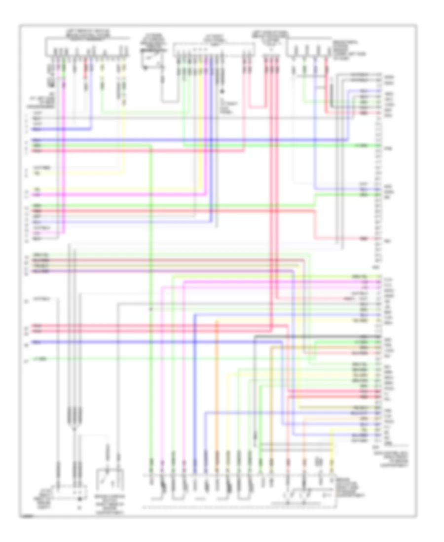
COOLING FAN
Cooling Fan Wiring Diagram for Toyota Celica GT 1991


List of elements for Cooling Fan Wiring Diagram for Toyota Celica GT 1991:
HORN
Horn Wiring Diagram for Toyota Celica GT 1991
List of elements for Horn Wiring Diagram for Toyota Celica GT 1991:
POWER DOOR LOCKS
Power Door Lock Wiring Diagram for Toyota Celica GT 1991
List of elements for Power Door Lock Wiring Diagram for Toyota Celica GT 1991:
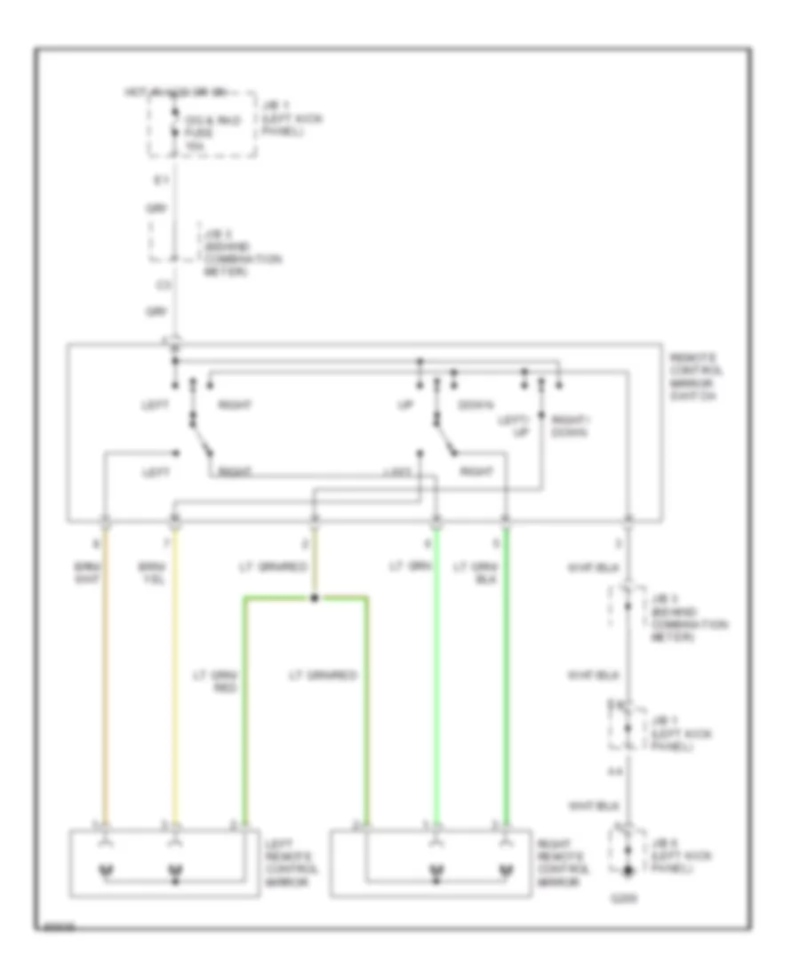
POWER MIRRORS
Power Mirror Wiring Diagram for Toyota Celica GT 1991
List of elements for Power Mirror Wiring Diagram for Toyota Celica GT 1991:
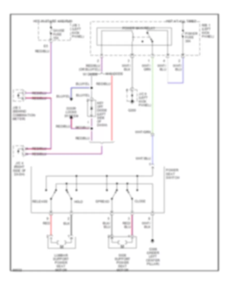
POWER SEATS
Power Seat Wiring Diagrams for Toyota Celica GT 1991
List of elements for Power Seat Wiring Diagrams for Toyota Celica GT 1991:
POWER WINDOWS
Power Window Wiring Diagram for Toyota Celica GT 1991
List of elements for Power Window Wiring Diagram for Toyota Celica GT 1991:
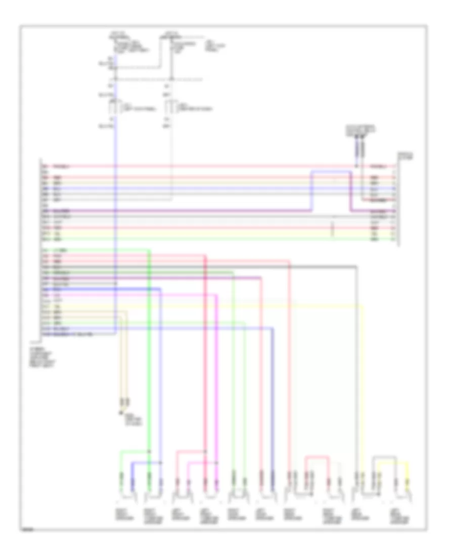
RADIO
Radio Wiring Diagrams, with CD Player for Toyota Celica GT 1991
List of elements for Radio Wiring Diagrams, with CD Player for Toyota Celica GT 1991:
Radio Wiring Diagrams, without CD Player for Toyota Celica GT 1991
List of elements for Radio Wiring Diagrams, without CD Player for Toyota Celica GT 1991:
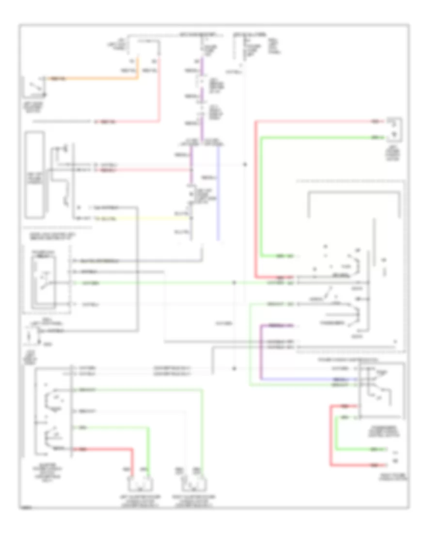
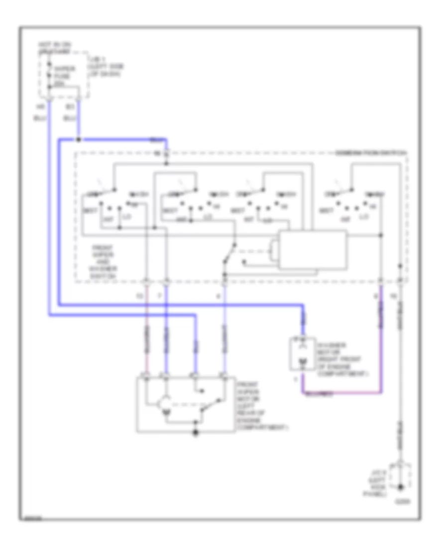
WIPER/WASHER
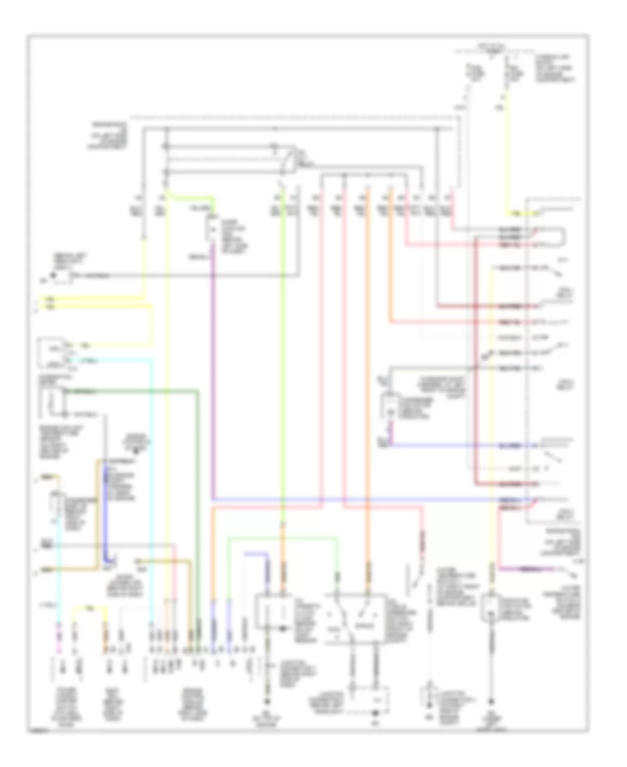
Front Washer/Wiper Wiring Diagram for Toyota Celica GT 1991
List of elements for Front Washer/Wiper Wiring Diagram for Toyota Celica GT 1991:
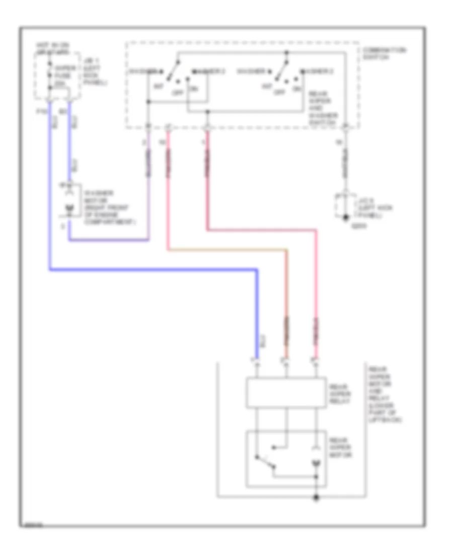
Rear Wiper/Washer Wiring Diagram for Toyota Celica GT 1991
List of elements for Rear Wiper/Washer Wiring Diagram for Toyota Celica GT 1991: