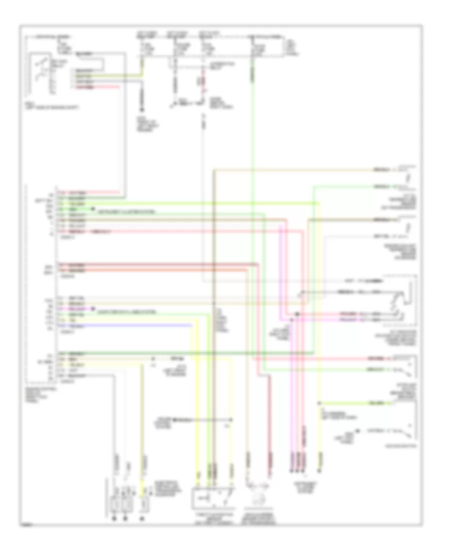
AIR CONDITIONING
A/C Wiring Diagram for Toyota T100 1995
 https://portal-diagnostov.com/license.html
Automotive Electricians Portal FZCO
Automotive Electricians Portal FZCO
https://portal-diagnostov.com/license.html
https://portal-diagnostov.com/license.html
Automotive Electricians Portal FZCO
Automotive Electricians Portal FZCO
List of elements for A/C Wiring Diagram for Toyota T100 1995:
- (2.7l a/t) (2.7l m/t)
- (3.4l a/t) (3.4l m/t)
- 1994 vftc c
- 2.7l
- A/c amplifier (right side of i/p)
- A/c dual pressure switch (right side of i/p)
- A/c fuse 10a
- A/c idle-up valve (rear of engine)
- A/c magnetic clutch (right front of engine)
- A/c switch
- A/c thermistor (right side of i/p)
- A7 b10 a20 b7
- All 3.4l and 1995
- Alt fuse 80a
- B8 a5
- Blower motor (right side of i/p)
- Blower resistor (right side of i/p)
- Blower switch
- C2 d1 c10 d2
- Engine control module (right side of i/p)
- Engine controls system (efi main relay)
- G200 (left kick panel)
- Gauge fuse 10a
- Heater fuse 30a
- Heater relay
- Hot at all times
- Hot in run or start
- Integration relay
- Interior lights system (rheostat)
- Interior lights system (tail fuse)
- J/b 1 (left kick panel)
- Off
- R/b 2 (left side of engine compt)
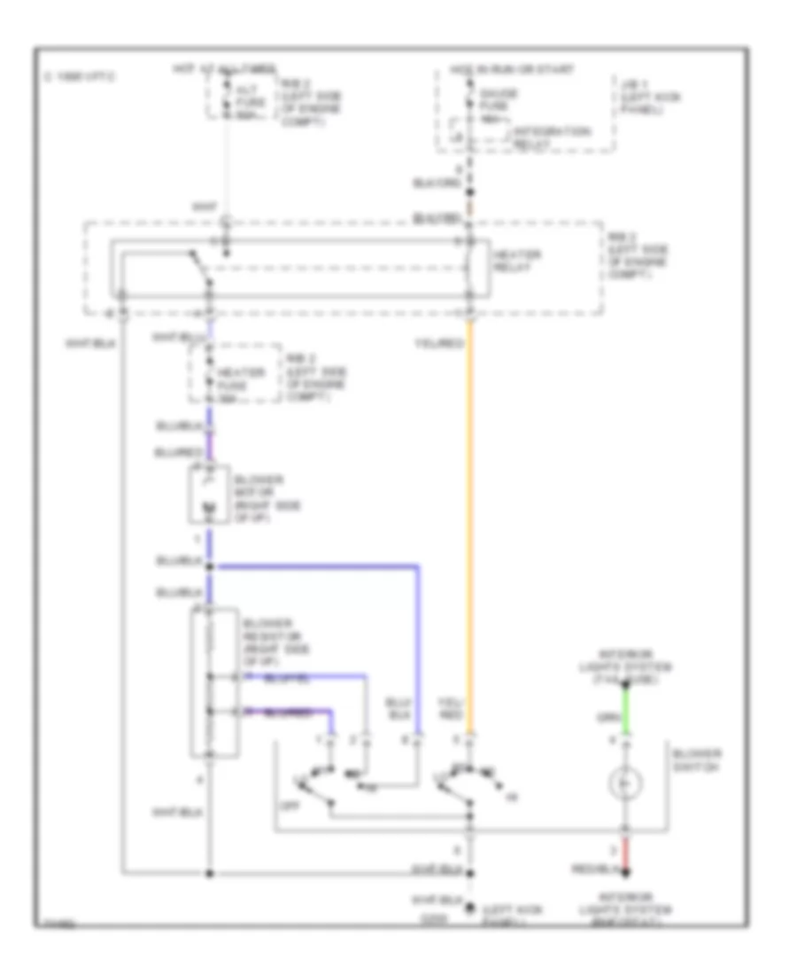
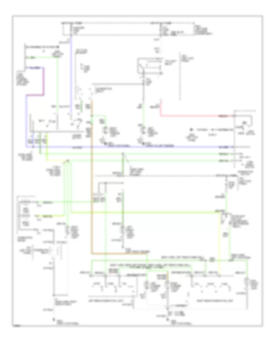
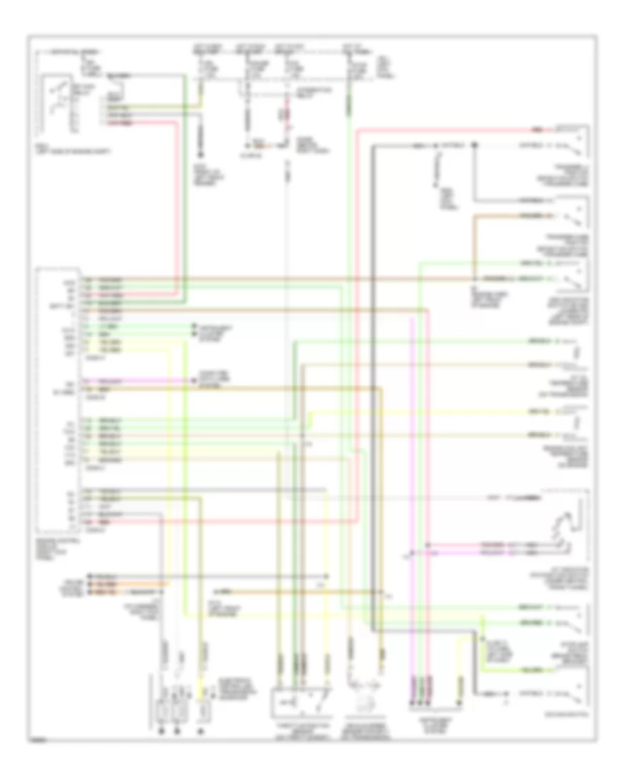
Heater Wiring Diagram for Toyota T100 1995
List of elements for Heater Wiring Diagram for Toyota T100 1995:
- (left kick panel)
- Alt fuse 80a
- Blower motor (right side of i/p)
- Blower resistor (right side of i/p)
- Blower switch
- C 1995 vftc
- G200
- Gauge fuse 10a
- Heater fuse 30a
- Heater relay
- Hot at all times
- Hot in run or start
- Integration relay
- Interior lights system (rheostat)
- Interior lights system (tail fuse)
- J/b 1 (left kick panel)
- Off
- R/b 2 (left side of engine compt)
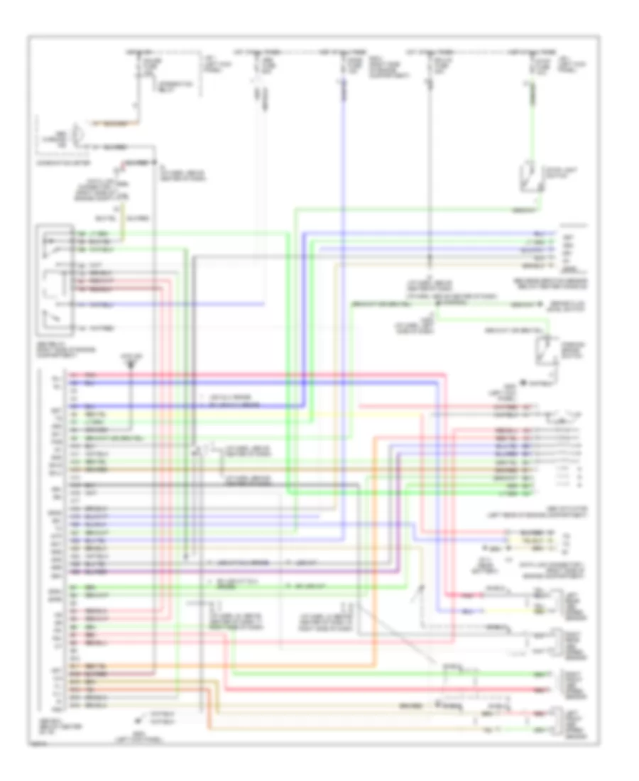
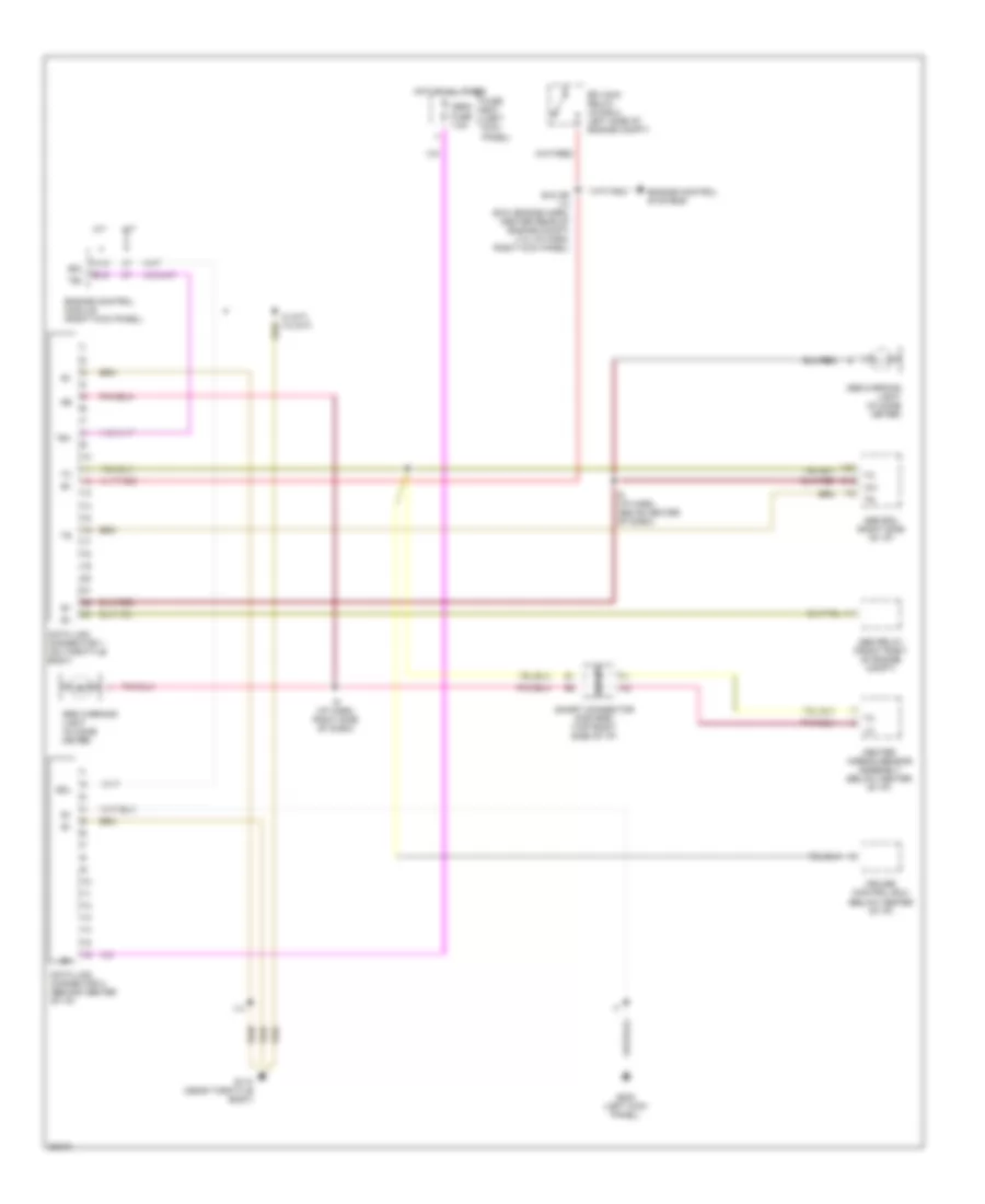
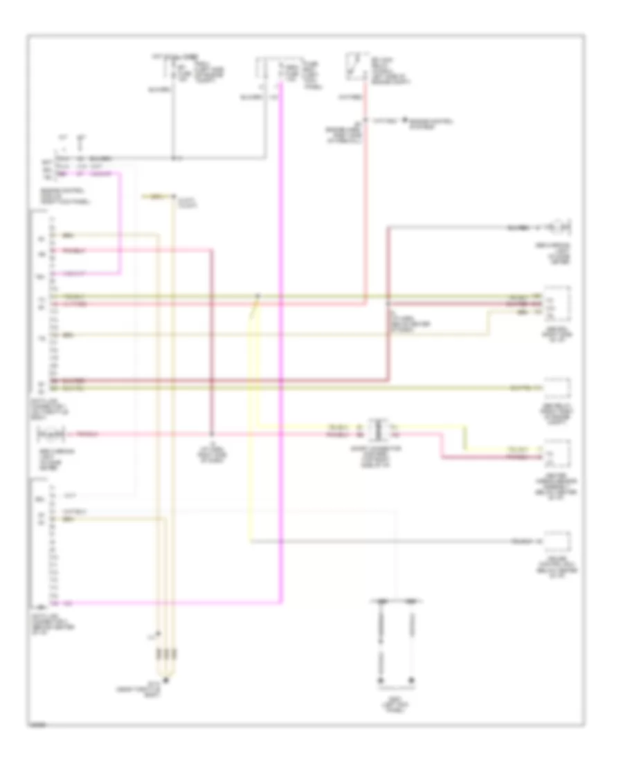
ANTI-LOCK BRAKES
Anti-lock Brake Wiring Diagrams for Toyota T100 1995
List of elements for Anti-lock Brake Wiring Diagrams for Toyota T100 1995:
- (i/p harn, above center of dash)
- (i/p harn, above center of dash) i6 (canada)
- (i/p harn, behind center of dash)
- 4wd ind
- A10
- A11
- A12
- A13
- A14
- A15
- A16
- A17
- A18
- A19
- A20
- A21
- A22
- A23
- A24
- A25
- A26
- Abs actuator (left rear of engine compartment)
- Abs deceleration sensor (below center console)
- Abs ecu (below center of i/p)
- Abs fuse 60a
- Abs relay (right side of engine compartment)
- Abs warning ind
- Ast
- B10
- B11
- B12
- B13
- B14
- B15
- B16
- Bat
- Brake fluid level switch
- Combination meter
- Data link connector 1 (right side of engine compartment)
- Data link wa connector 1 (right side of wb engine compt)
- Dome fuse 15a
- Ecu-ig fuse 20a
- Ex usa a/t
- Ex usa dlx grade
- Ex usa m/t dlx grade
- Ex1
- Fl+
- Fl-
- Fr+
- Fr-
- Fss
- G111 (near battery)
- G200 (left kick panel)
- Gauge fuse 10a
- Ggnd
- Gnd
- Gs1
- Gs2
- Gst
- Hot at all times
- Hot in on
- I10
- I4 (usa) (i/p harn, left side of dash)
- I6 (i/p harn, above center of dash)
- I6 i7
- I6 i9 (i/p harn, i6: above center of dash; i7: right side of dash)
- I8 i9 (i/p harn, i8: behind center of dash; i9: right side of dash)
- Ig1
- Integration relay
- J/b 1 (left kick panel)
- Left front abs speed sensor
- Left rear abs speed sensor
- Light
- Parking brake switch
- Pkb
- Pnk
- R/b 2 (right side of engine compartment)
- Red
- Right front abs speed sensor
- Right rear abs speed sensor
- Rl+
- Rl-
- Rr+
- Rr-
- Rss
- Sflh
- Sflr
- Sfrh
- Sfrr
- Shield
- Srh
- Srr
- Stop fuse 15a
- Stop light switch
- Stp
- Usa a/t
- Usa dlx grade
- Usa m/t dlx grade
COMPUTER DATA LINES
2.7L
2.7L, Computer Data Lines for Toyota T100 1995
List of elements for 2.7L, Computer Data Lines for Toyota T100 1995:
- A/t
- A19
- A20
- Abs ecu (right side of i/p)
- Abs relay (front right of engine compt)
- Abs warning light (in comb meter)
- B12
- B15
- Center airbag sensor assembly (below center of i/p)
- Cruise control ecu (below center of i/p)
- Data link connector 1 (on throttle body)
- Data link connector 3 (behind center of i/p)
- E18 or i14 (e18- engine harn, center rear of engine compt) (i14- i/p harn, right kick panel)
- Efi main relay (in r/b 2, left side of engine compt)
- Engine control module (right kick panel)
- Engine control systems
- Fuse box (left kick panel)
- G110 (near throttle body)
- G200 (left kick panel)
- Hot at all times
- I14
- I2 (a/t) i12 (m/t)
- I6 (i/p harn, above center of dash)
- I9 (i/p harn, right side of dash)
- M/t
- Obd2 fuse 7.5a
- Sdl
- Short connector (for srs) (top right side of i/p)
- Srs warning light (in comb meter)
- Te1
3.4L
3.4L, Computer Data Lines for Toyota T100 1995
List of elements for 3.4L, Computer Data Lines for Toyota T100 1995:
- A/t
- A14
- A18
- A19
- A20
- Abs ecu (right side of i/p)
- Abs relay (front right of engine compt)
- Abs warning light (in comb meter)
- B12
- Bat
- Center airbag sensor assembly (below center of i/p)
- Cruise control ecu (below center of i/p)
- Data link connector 1 (on throttle body)
- Data link connector 3 (behind center of i/p)
- E3 (engine harn, right side of firewall)
- Efi fuse 15a
- Efi main relay (in r/b 2, left side of engine compt)
- Engine control module (right kick panel)
- Engine control systems
- Fuse box (left kick panel)
- G110 (near throttle body)
- G200 (left kick panel)
- Hot at all times
- I14
- I2 (a/t) i12 (m/t)
- I6 (i/p harn, above center of dash)
- I9 (i/p harn, right side of dash)
- M/t
- Obd2 fuse 7.5a
- R/b 2 (left side of engine compt)
- Sdl
- Short connector (for srs) (top right side of i/p)
- Srs warning light (in comb meter)
- Te1
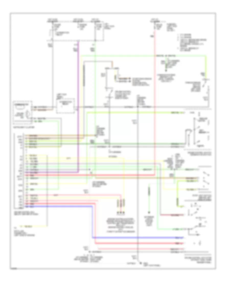
CRUISE CONTROL
Cruise Control Wiring Diagram for Toyota T100 1995
List of elements for Cruise Control Wiring Diagram for Toyota T100 1995:
- (1995 only) (i/p harness, top left end of dash)
- (1995)
- (a/t)
- (body harness, inside left door) b1
- (i/p harness, above center of dash)
- (left kick panel) j/b 1
- (m/t)
- (throttle position sensor)
- (usa)
- 2.7l engine
- 3.4l engine
- Batt
- C13
- Cancel
- Ccs
- Cruise control actuator (on right side, inner
- Cruise control clutch switch (under left side of dash)
- Cruise control ecu (below center of dash)
- Cruise control ind
- Cruise control switch (combination switch)
- Data link connector 1 (left side of engine)
- Ect
- Ecu-b fuse 15a
- Engine controls system (engine and electronically controlled transmission ecu) (a/t) (engine control module) (m/t)
- Engine fuse 10a
- Exterior lights system (stop light)
- Fender panel)
- Fuse box (left kick panel, on j/b 1)
- G200 (left kick panel)
- Gauge fuse 10a
- Gnd
- Hot at all times
- Hot in on and start
- I6 i9 (i/p harness, right side of dash)
- I7 (i/p harness,
- Idl
- Instrument cluster
- Integration relay
- J/b 1 (left kick panel)
- Left side of dash) (usa)
- Main
- N&c
- Of dash)
- Parking brake switch (behind left side off dash)
- Pkb
- Red
- Resume/ accel
- Set/ coast
- Spd
- Speedometer
- Starting/charging system (park/neutral position switch)
- Stop fuse 15a
- Stop light switch (behind left side of dash)
- Stp+
- Stp-
- Usa 3.4l engine m/t dlx grade
- Usa 3.4l engine sr5 grade, usa 3.4l engine a/t dlx grade, canada, 2.7l engine
- Vr1
- Vr2
- Vr3
- Warning systems (brake fluid level warning) (usa only)
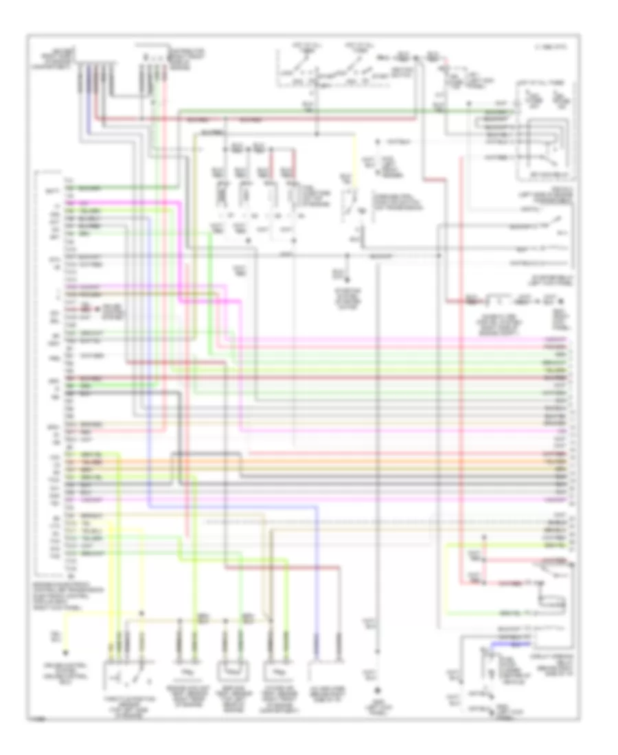
ENGINE PERFORMANCE
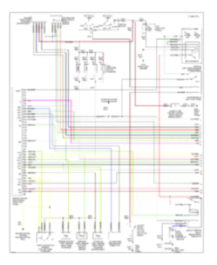
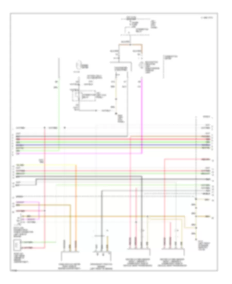
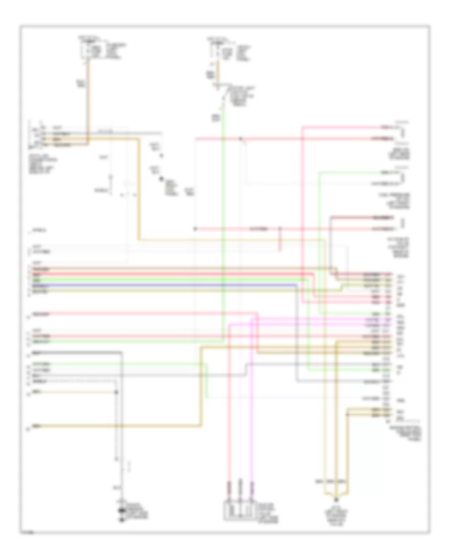
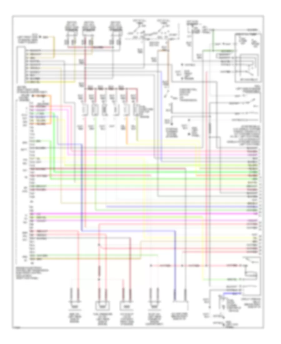
2.7L
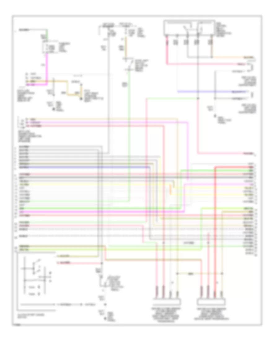
2.7L, Engine Performance Wiring Diagrams, A/T (1 of 3) for Toyota T100 1995
List of elements for 2.7L, Engine Performance Wiring Diagrams, A/T (1 of 3) for Toyota T100 1995:
- (right kick panel)
- (right side of engine compartment)
- 1995 vftc c
- A/c amplifier (behind right side of i/p)
- A10
- A11
- A12
- A13
- A14
- A15
- A16
- A17
- A18
- A19
- A20
- A21
- A22
- Acc
- Aci
- Act
- Am1 fuse 40a
- B10
- B11
- B12
- Batt
- C10
- C11
- C12
- C13
- C14
- C15
- C16
- C17
- Circuit opening relay (behind right side of i/p)
- Cruise control system
- Cruise control system (cruise control ecu)
- Distributor (right front side of g+
- Efi fuse 15a
- Efi main relay
- Egr gas temp. sensor (top left rear of engine)
- Engine & electronic controlled transmission electronic control module (ecm)
- Engine coolant temp. sensor (right rear of engine)
- Engine)
- Fuel injectors (on top of engine)
- Fuel pump (under center of vehicle)
- G100 (left front fender)
- G200 (left kick panel)
- G203 (right kick panel)
- Hot at all times
- Idl
- Ig2
- Ign fuse 7.5a
- Igniter
- Ignition switch
- Intake air temp. sensor (right front of engine compartment)
- J/b 1 (left kick panel)
- Knk
- Lock
- Ne-
- Noise filter (for ign, system) (right side of engine compt.)
- Nsw
- Od1
- Od2
- Ox1
- Ox2
- P/n
- Park/neutral position switch (on transmission)
- Prg
- R/b no.2 (left side of engine compartment)
- Red
- Sdl
- Sp1
- Sp2+
- Sp2-
- St1
- Sta
- Start
- Starter relay (left kick panel)
- Starting system (starter motor)
- Te1
- Tha
- Thg
- Throttle position sensor (top left side of engine)
- Thw
- Vcc
- Vta
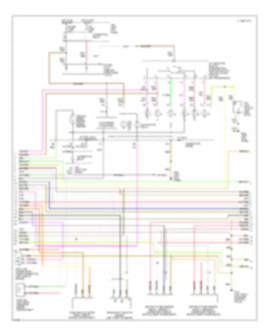
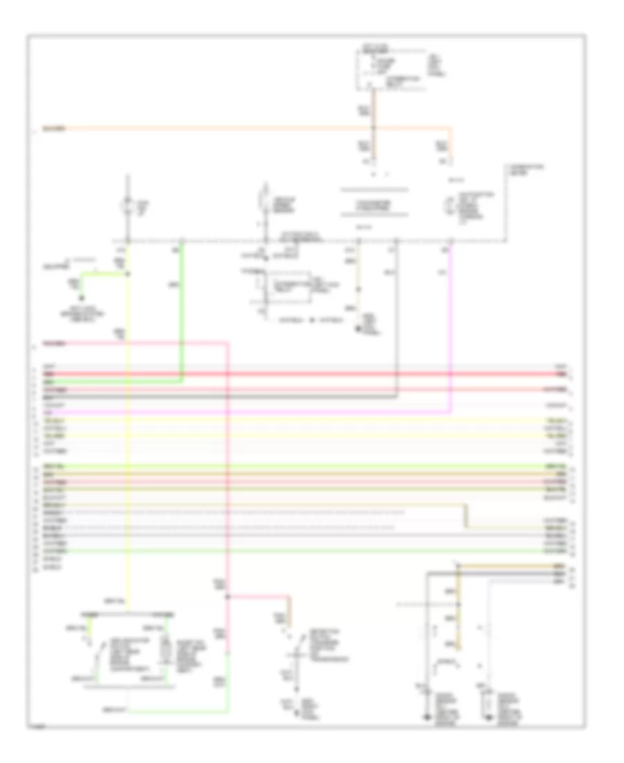
2.7L, Engine Performance Wiring Diagrams, A/T (2 of 3) for Toyota T100 1995
List of elements for 2.7L, Engine Performance Wiring Diagrams, A/T (2 of 3) for Toyota T100 1995:
- (w/tach. only) voltmeter rtn
- 1995 vftc c
- A/t indicator switch (park/neutral position switch) (neutral start switch) (on transmission)
- Cig fuse 15a
- Combination meter
- Crankshaft position sensor (left front of engine)
- D10
- D12
- Data link connector #1 (check connector) (left side of engine)
- Diode (a/t) (behind right side of i/p)
- Evap vsv (left rear corner of engine compartment)
- G110 (left front of engine, near fpu valve)
- G200 (left kick panel)
- Gauge fuse 10a
- Heated oxygen sensor (bank 1, sensor 1) (under right side of vehicle, near transmission)
- Heated oxygen sensor (bank 1, sensor 2) (under right side of vehicle, near transmission)
- Hot in acc or on
- Hot in on or start
- Integration relay
- J/b 1 (left kick panel)
- Malfunction ind lp
- Mass air flow meter (right side of engine compartment)
- Ne-
- O/d main switch (left side of i/p)
- O/d off ind lp
- Shield
- Tachometer (if equipped)
- Te1
- Vehicle speed sensor (speed sensor)
- W/ tach. only
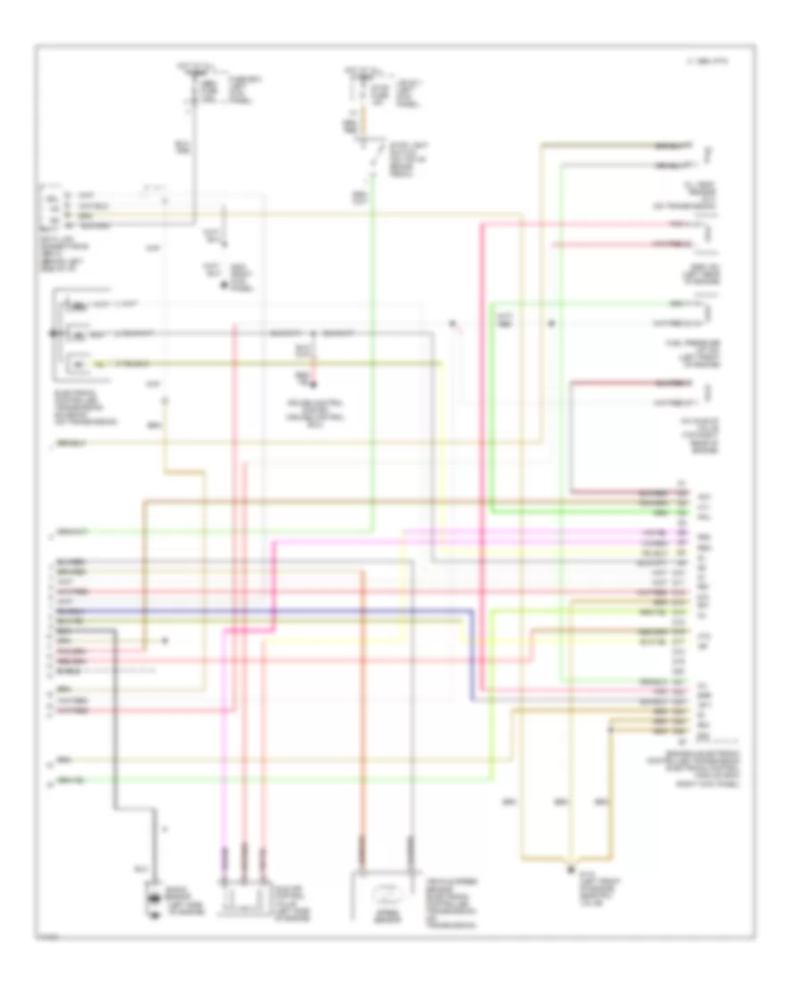
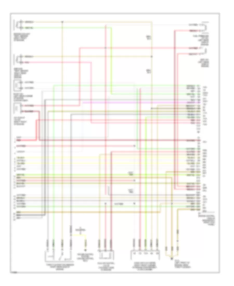
2.7L, Engine Performance Wiring Diagrams, A/T (3 of 3) for Toyota T100 1995
List of elements for 2.7L, Engine Performance Wiring Diagrams, A/T (3 of 3) for Toyota T100 1995:
- #10
- #20
- (left side of engine)
- (right kick panel)
- 1995 vftc c
- A/c idle-up valve (top right rear of engine)
- Acv
- Batt
- Cruise control system (cruise control ecu)
- D15
- D18
- D19
- D20
- D22 pnk
- Data link connector #3 (obd 2) (behind left side of i/p)
- E01
- E02
- E03
- Egr
- Egr vsv (left rear of engine)
- Electronic controlled transmission solenoid (on transmission)
- Engine & electronic controlled transmission electronic control module (ecm)
- Fpu
- Fuel pressure up vsv (left front of engine)
- Fuse box (left kick panel)
- G110 (left front of engine, near fpu valve)
- G203 (right kick panel)
- Hot at all times
- Ht1
- Ht2
- Idle air control valve (left side of engine)
- Igf
- Igt1
- J/b no.1 (left kick panel)
- Knock
- Obd2 fuse 7.5a
- Oil
- Oil temp. sensor (a/t) (on transmission)
- Pnk
- Rsc
- Rso
- Sdl
- Sensor
- Speed sensor
- Stop fuse 15a
- Stop light switch (on top of brake pedal)
- Vehicle speed sensor (electronic controlled transmission) (on transmission)
2.7L, Engine Performance Wiring Diagrams, M/T (1 of 3) for Toyota T100 1995
List of elements for 2.7L, Engine Performance Wiring Diagrams, M/T (1 of 3) for Toyota T100 1995:
- (right side of engine compartment)
- 1995 vftc c
- A/c amplifier (behind right side of i/p)
- A10
- A11
- A12
- A13
- A14
- A15
- A16
- A17
- A18
- A19
- A20
- A21
- A22
- Ac1
- Acc
- Act
- Am1 fuse 40a
- B10
- B11
- B12
- B13
- B14
- B15
- B16
- Batt
- C17
- Circuit opening relay (behind right side of i/p)
- Clutch start switch (on top of clutch pedal)
- Cruise control system (cruise control ecu)
- Distributor (right front side of g+
- Efi fuse 15a
- Efi main relay
- Egr gas temp. sensor (top left rear of engine)
- Engine control module (ecm) (right kick panel)
- Engine coolant temp. sensor (right rear of engine)
- Engine)
- Fuel injectors (on top of engine)
- Fuel pump (under center of vehicle)
- G100 (front left fender)
- G200 (left kick panel)
- G200 (left kick panel)
- G203 (right kick panel)
- Hot at all times
- Idl
- Ig2
- Ign fuse 7.5a
- Igniter
- Ignition switch
- Intake air temp. sensor (right front of engine compartment)
- J/b 1 (left kick panel)
- Knk
- Lock
- Noise filter (for ign. system) (right side of engine compt.)
- Ox1
- Ox2
- R/b no.2 (left side of engine compartment)
- Red
- Sdl
- Shield
- Sp1
- St1
- Sta
- Start
- Starter relay (left kick panel)
- Starting system (starter motor)
- Te1
- Tha
- Thg
- Throttle position sensor (top left side of engine)
- Thw
- Vcc
- Vta
2.7L, Engine Performance Wiring Diagrams, M/T (2 of 3) for Toyota T100 1995
List of elements for 2.7L, Engine Performance Wiring Diagrams, M/T (2 of 3) for Toyota T100 1995:
- (w/tach. only) voltmeter rtn
- 1995 vftc c
- Combination meter
- Crankshaft position sensor (left front of engine)
- D10
- D12
- Data link connector #1 (check connector) (left side of engine)
- Evap vsv (left rear corner of engine compartment)
- G110 (left front of engine, near fpu valve)
- G200 (left kick panel)
- Gauge fuse 10a
- Heated oxygen sensor (bank 1, sensor 1) (under right side of vehicle, near transmission)
- Heated oxygen sensor (bank 1, sensor 2) (under right side of vehicle, near transmission)
- Hot in on or start
- Integration relay
- J/b 1 (left kick panel)
- Malfunction indicator lamp (check engine warning lamp)
- Mass air flow meter (right side of engine compartment)
- Ne-
- Red
- Shield
- Speed meter
- Tachometer (if equipped)
- Te1
2.7L, Engine Performance Wiring Diagrams, M/T (3 of 3) for Toyota T100 1995
List of elements for 2.7L, Engine Performance Wiring Diagrams, M/T (3 of 3) for Toyota T100 1995:
- #10
- #20
- A/c idle-up valve (top right rear of engine)
- Acv
- Batt
- C16
- C19
- C21
- C22
- C24
- Data link connector #3 (obd 2) (behind left side of i/p)
- E01
- E02
- E03
- Egr
- Egr vsv (left rear of engine)
- Engine control module (ecm) (right kick panel)
- Fpu
- Fuel pressure up vsv (left front of engine)
- Fuse box (left kick panel)
- G110 (left front of engine, near fpu valve)
- G203 (right kick panel)
- Hot at all times
- Ht1
- Ht2
- Idle air control valve (left side of engine)
- Igf
- J/b no.1 (left kick panel)
- Knock sensor (left side of engine)
- Ne-
- Obd2 fuse 7.5a
- Pnk
- Prg
- Red
- Rsc
- Rso
- Sdl
- Shield
- Stop fuse 15a
- Stop light switch (on top of brake pedal)
3.4L
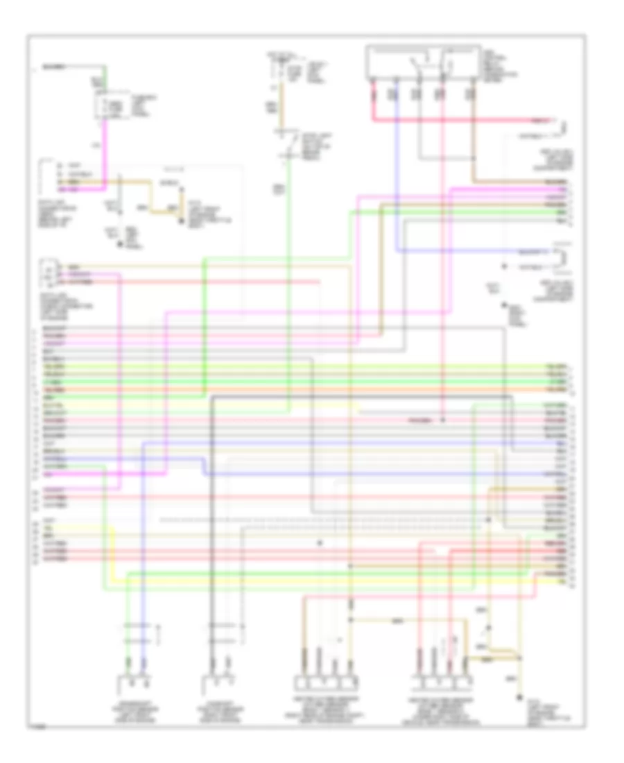
3.4L, Engine Performance Wiring Diagrams, A/T (1 of 4) for Toyota T100 1995
List of elements for 3.4L, Engine Performance Wiring Diagrams, A/T (1 of 4) for Toyota T100 1995:
- (on transmission)
- 4wd
- A/c amplifier (behind right side of i/p)
- A/c idle-up valve (top right front side of engine)
- A10
- A11
- A12
- A13
- A14
- A15
- A16
- A17
- A18
- A19
- A20
- A21
- A22
- A23
- A24
- A25
- A26
- A27
- A28
- Ac1
- Acc
- Act
- Acv
- Am1
- Am1 fuse 40a
- Am2
- B10
- B11
- B12
- B13
- B14
- B15
- B16
- Batt
- C17
- Circuit opening relay (behind right side of i/p)
- Cruise control system
- Efi fuse 15a
- Efi main relay
- Egr
- Egr vsv (left rear side of engine)
- Engine & electronic controlled transmission electronic control module (ecm) (right kick panel)
- Evap vsv (left rear corner of engine compartment)
- Fpu
- Fuel injectors (on top of engine)
- Fuel pressure up vsv (left rear side of engine)
- Fuel pump (under center of vehicle)
- G100 (front left fender)
- G110 (left front side of engine, near throttle body)
- G200 (left kick panel)
- Hot at all times
- Hot in on or start
- If equipped
- Ig2
- Ign fuse 7.5a
- Igniter (right front side of engine compartment)
- Ignition coil no.1 (right side of engine)
- Ignition coil no.2 (right side of engine)
- Ignition coil no.3 (right side of engine)
- Ignition switch
- J/b 1 (left kick panel)
- Lock
- Od1
- Od2
- Oilw
- P&n
- Park/neutral position switch
- Prg
- R/b 2 (left side of engine compartment)
- Red
- Sdl
- Spd
- St1
- Start
- Starter relay (u.s. models: w/power window, canada a/t & m/t w/power window (in j/b 1: left kick panel) (u.s. & canada m/t models w/o power window (left kick panel)
- Starting/ charging system (starter)
- Te1
- Tfn
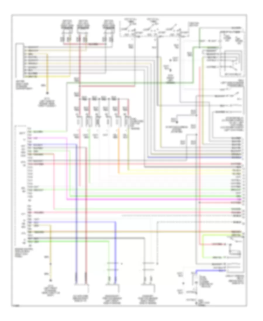
3.4L, Engine Performance Wiring Diagrams, A/T (2 of 4) for Toyota T100 1995
List of elements for 3.4L, Engine Performance Wiring Diagrams, A/T (2 of 4) for Toyota T100 1995:
- Add control relay (behind combination meter)
- Add valve 2 (left side of engine compartment)
- Add valve 4 (left side of engine compartment)
- Camshaft position sensor (right front side of engine)
- Crankshaft position sensor (left front side of engine)
- Data link connector #1 (check connector) (left side of engine)
- Data link connector #3 (obd2) (behind left side of i/p)
- Fuse box (left kick panel)
- G110 (left front of engine, near throttle body)
- G200 (left kick panel)
- G203 (right kick panel)
- Heated oxygen sensor (oxygen sensor) (bank 1 sensor 1) (right rear of engine compt., near transmission)
- Heated oxygen sensor (oxygen sensor) (bank 1 sensor 2) (under right side of vehicle, near transmission)
- Hot at all times
- Ht1
- Ht2
- J/b no.1 (left kick panel)
- Ne-
- Obd2 fuse 7.5a
- Ox1
- Ox2
- Pnk
- Red
- Shield
- Stop fuse 15a
- Stop light switch (on top of brake pedal)
- Te1
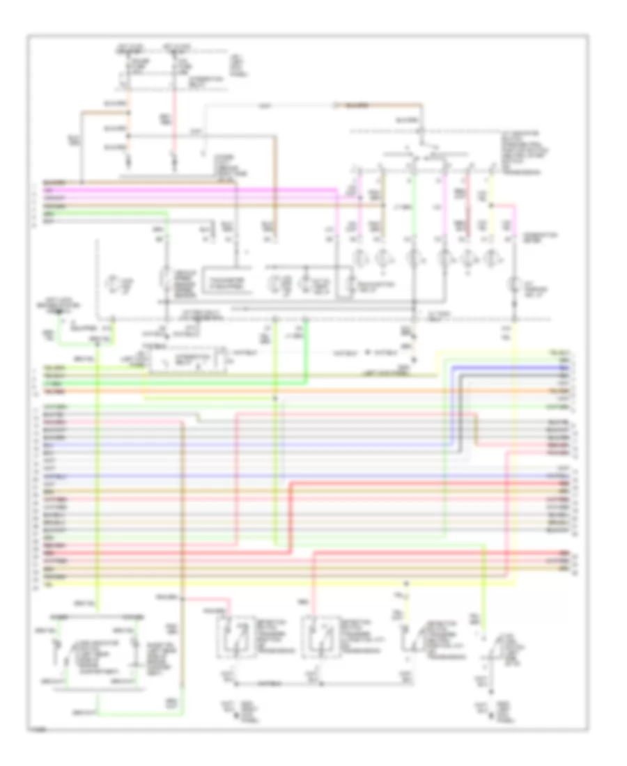
3.4L, Engine Performance Wiring Diagrams, A/T (3 of 4) for Toyota T100 1995
List of elements for 3.4L, Engine Performance Wiring Diagrams, A/T (3 of 4) for Toyota T100 1995:
- (w/tach only) voltmeter rtn
- 4wd
- 4wd ind. lp
- A/t indicator switch (park/neutral position switch) (neutral start switch) (on transmission)
- A/t oil temp. ind lp
- A/t parking ind. lp
- A10
- A12
- Add indicator switch (left rear side of engine compartment)
- Anti-lock brakes system (abs ecu)
- Cig fuse 15a
- Combination meter
- D10
- Detection switch (transfer l4 position, a/t) (on transmission)
- Detection switch (transfer neutral position, a/t) (on transmission)
- Detection switch (transfer position) (on transmission)
- Diode (a/t) (behind right side of i/p)
- G200 (left kick panel)
- G203 (right kick panel)
- G20o (left kick panel)
- Gauge fuse 10a
- Hot in acc or on
- Hot in on or start
- If equipped
- Integration relay
- J/b 1 (left kick panel)
- Malfunction ind lp.
- O/d main switch (left side of i/p)
- O/d off ind lp
- Red
- Short pin (left rear side of engine compart- ment)
- Tachometer (if equipped)
- Vehicle speed sensor (speed sensor)
- W/ tach. only
- W/add
- W/o add
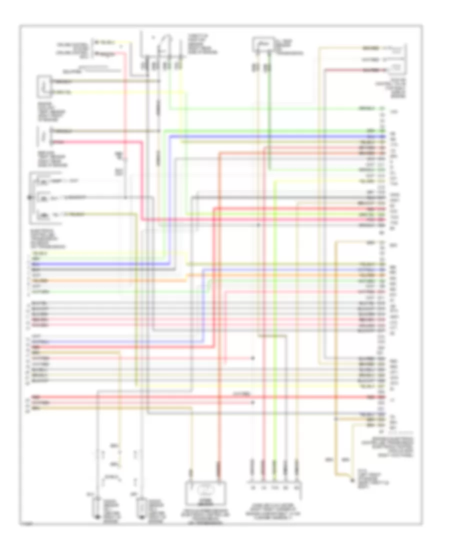
3.4L, Engine Performance Wiring Diagrams, A/T (4 of 4) for Toyota T100 1995
List of elements for 3.4L, Engine Performance Wiring Diagrams, A/T (4 of 4) for Toyota T100 1995:
- #10
- #20
- #30
- #40
- #50
- #60
- (right kick panel)
- C10
- C11
- C12
- C13
- C14
- C15
- C16
- C17
- C18
- C19
- C20
- C21
- C22
- Cruise control system (cruise control ecu)
- D10
- D11
- D12
- D13
- D14
- D15
- D16
- D17
- D18
- D19
- D20
- D21
- D22
- D23
- D24
- D25
- D26
- D27
- D28
- D29
- D30
- D31
- D32
- D33
- D34
- E01
- E02
- Egr gas temp. sensor (right rear side of engine)
- Electronic controlled transmission solenoid (on transmission)
- Engine coolant temp. sensor (right front of engine)
- Engine & electronic controlled transmission electronic control module (ecm)
- Eo3
- G110 (left front of engine, near throttle body)
- Ht1
- Ht2
- Idl
- Idle air control valve (top right side of engine)
- If equipped
- Igf
- Igt1
- Igt2
- Igt3
- Knk1
- Knk2
- Knock sensor no.1 (center front of engine)
- Knock sensor no.2 (center front of engine)
- Mass air flow meter (right front corner of engine compartment, in air cleaner assembly)
- Ne-
- Nsw
- Oil
- Oil temp sensor (on transmission)
- Ox1
- Ox2
- Pnk
- Red
- Rsc
- Rso
- Shield
- Sp2
- Speed sensor
- Sta
- Tha
- Thg
- Throttle position sensor (right rear side of engine)
- Thw
- Vcc
- Vehicle speed sensor (electronic controlled transmission) (on transmission)
- Vta
3.4L, Engine Performance Wiring Diagrams, M/T (1 of 4) for Toyota T100 1995
List of elements for 3.4L, Engine Performance Wiring Diagrams, M/T (1 of 4) for Toyota T100 1995:
- 4wd
- A/c amplifier (behind right side of i/p)
- A10
- A11
- A12
- A13
- A14
- A15
- A16
- A17
- A18
- A19
- A20
- A21
- A22
- Ac1
- Acc
- Act
- Am1
- Am1 fuse 40a
- Am2
- B10
- B11
- B12
- Batt
- Camshaft position sensor (right front side of engine)
- Circuit opening relay (behind right side of i/p)
- Crankshaft position sensor (left front side of engine)
- E03
- Efi fuse 15a
- Efi main relay
- Engine control module (ecm) (right kick panel)
- Fuel injectors (on top of engine)
- Fuel pump (under center of vehicle)
- G100 (front left fender)
- G110 (left front of engine, near throttle body)
- G110 (left side of engine, near throttle body)
- Hot at all times
- Ht1
- Ht2
- Ig1
- Ig2
- Igniter (right side of engine compartment)
- Ignition coil no.1 (right side of engine)
- Ignition coil no.2 (right side of engine)
- Ignition coil no.3 (right side of engine)
- Ignition switch
- Lock
- Ne-
- R/b 2 (left side of engine compartment)
- Red
- Sdl
- Shield
- Spd
- St1
- Sta
- Start
- Starter relay (w/ power window) (in j/b 1: left kick panel) (w/o power window) (left kick panel)
- Starting/charging system (starter)
3.4L, Engine Performance Wiring Diagrams, M/T (2 of 4) for Toyota T100 1995
List of elements for 3.4L, Engine Performance Wiring Diagrams, M/T (2 of 4) for Toyota T100 1995:
- Add control relay (behind combination meter)
- Add valve 2 (left side of engine compartment)
- Add valve 4 (left side of engine compartment)
- C17
- Clutch start cancel switch
- Clutch start switch (on top of clutch pedal)
- Data link connector #1 (check connector) (left side of engine)
- Data link connector #3 (obd2) (behind left side of i/p)
- Fuse box (left kick panel)
- G110 (left front of engine, near throttle body)
- G200 (left kick panel)
- G203 (right kick panel)
- Heated oxygen sensor (oxygen sensor) (bank 1 sensor 1) (right rear of engine compartment, near transmission)
- Heated oxygen sensor (oxygen sensor) (bank 1 sensor 2) (under right side of vehicle, near transmission)
- Hot at all times
- Hot in on or start
- Ign fuse 7.5a
- J/b 1 (left kick panel)
- Obd2 fuse 7.5a
- Pnk
- Red
- Shield
- Stop fuse 15a
- Stop light switch (on top of brake pedal)
- Te1
3.4L, Engine Performance Wiring Diagrams, M/T (3 of 4) for Toyota T100 1995
List of elements for 3.4L, Engine Performance Wiring Diagrams, M/T (3 of 4) for Toyota T100 1995:
- anti-lock brakes system (abs ecu)
- (w/tach only) voltmeter rtn
- 4wd ind. lp
- A12
- Add indicator switch (left rear side of engine compartment)
- Combination meter
- D10
- D12
- Detection switch (transfer position) (on transmission)
- G200 (left kick panel)
- G203 (right kick panel)
- Gauge fuse 10a
- Hot in on or start
- If equipped
- Integration relay
- J/b 1 (left kick panel)
- Knock sensor no.1 (center front of engine)
- Knock sensor no.2 (center front of engine)
- Malfunction ind. lp (check engine warning lt)
- Red
- Shield
- Short pin (left rear side of engine compart- ment)
- Tachometer (if equipped)
- Vehicle speed sensor
- W/add
- W/o add
3.4L, Engine Performance Wiring Diagrams, M/T (4 of 4) for Toyota T100 1995
List of elements for 3.4L, Engine Performance Wiring Diagrams, M/T (4 of 4) for Toyota T100 1995:
- #10
- #20
- #30
- #40
- #50
- #60
- A/c idle-up valve (right front of engine)
- Acv
- C10
- C11
- C12
- C13
- C14
- C15
- C16
- Cruise control system (cruise control ecu)
- D10
- D11
- D12
- D13
- D14
- D15
- D16
- D17
- D18
- D19
- D20
- D21
- D22
- D23
- D24
- D25
- D26
- Egr
- Egr gas temp. sensor (right rear side of engine)
- Egr vsv (left rear side of engine)
- Engine control module (engine ecu) (right kick panel)
- Engine coolant temp. sensor (right front of engine)
- Eo1
- Eo2
- Evap vsv (left rear corner of engine compartment)
- Fpu
- Fuel pressure up vsv (left rear side of engine)
- G110 (left front of engine, near throttle body)
- Idl
- Idle air control valve (top right side of engine)
- If equipped
- Ig3
- Igf
- Igt1
- Igt2
- Knk1
- Knk2
- Mass air flow meter (right front corner of engine compartment, in air cleaner)
- Ox1
- Ox2
- Pnk
- Prg
- Red
- Rsc
- Rso
- Te1
- Tha
- Thg
- Throttle position sensor (right rear side of engine)
- Thw
- Vcc
- Vta
EXTERIOR LIGHTS
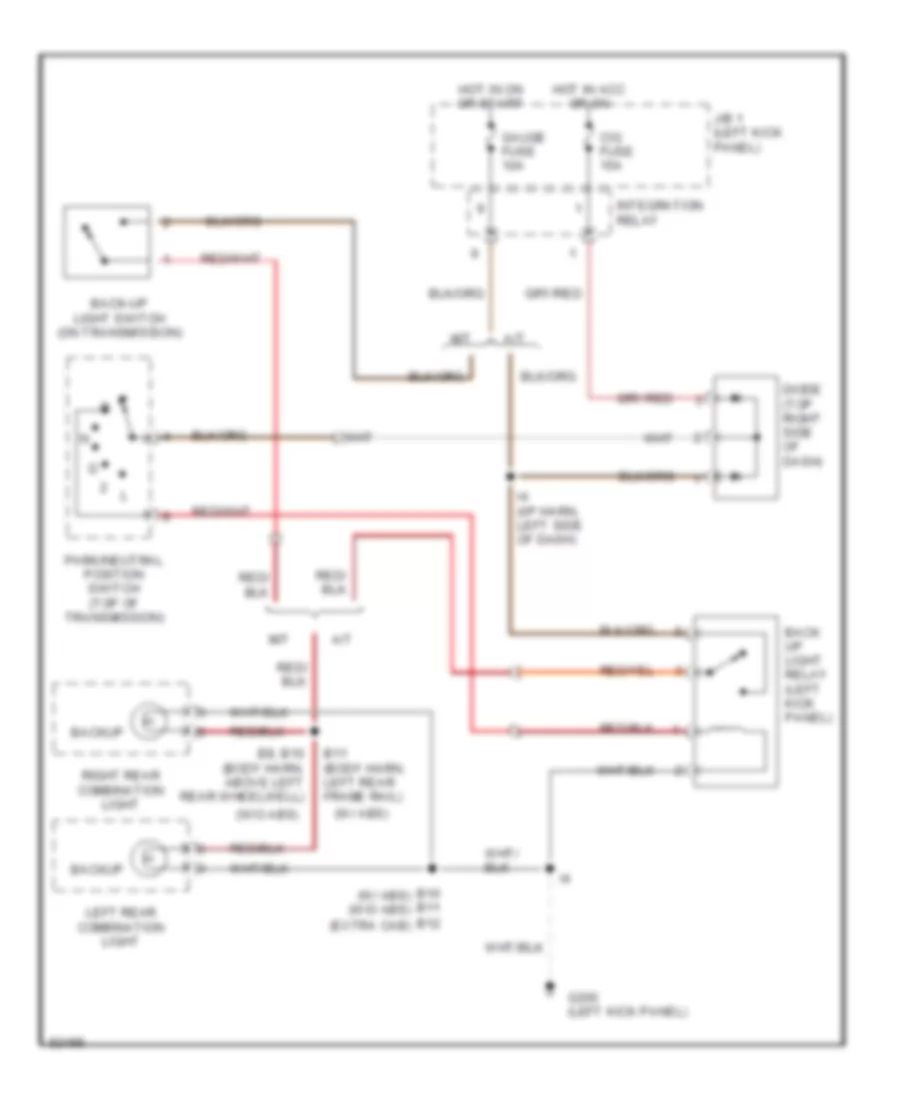
Back-up Lamps Wiring Diagram for Toyota T100 1995
List of elements for Back-up Lamps Wiring Diagram for Toyota T100 1995:
- (w/ abs)
- (w/o abs)
- A/t
- B10 (w/ abs) b11 (w/o abs)
- B11 (body harn, left rear frame rail)
- B12 (extra cab)
- B8, b10 (body harn, above left rear wheelwell)
- Back up light relay (left kick panel)
- Back-up light switch (on transmission)
- Backup
- Cig fuse 15a
- Diode (top right side of dash)
- G200 (left kick panel)
- Gauge fuse 10a
- Hot in acc or on
- Hot in on or start
- I4 (i/p harn, left side of dash)
- Integration relay
- J/b 1 (left kick panel)
- Left rear combination light
- M/t
- Park/neutral position switch (top of transmission)
- Right rear combination light
Exterior Lamps Wiring Diagram for Toyota T100 1995
List of elements for Exterior Lamps Wiring Diagram for Toyota T100 1995:
- (1995, 96, 97) (1998)
- (body harn, left kick panel) b1
- (body harn, left rear wheelwell) b10
- (body harn, rear left frame) (body harn, left rear wheelwell) b10
- (w/ abs)
- (w/ abs) (w/o abs)
- (w/o abs)
- Alt fuse 80a 100a
- B11
- C10
- C11
- C12
- Combination meter
- Combination switch
- G100 (front of left fender)
- G100 (left front fender)
- G200 (left kick panel)
- G203 (right kick panel)
- Haz-horn fuse 15a
- Hazard switch
- Head
- High mount stop light
- Hot at all times
- Hot in on or start
- I6 or i7
- I7 (dash harn, left side of dash)
- I7 or i4 (dash harn, left side of dash)
- I9 (dash harn, right side of dash)
- Integration relay
- J/b 1 (left kick panel)
- Left front parking light
- Left front turn signal light
- Left license plate light
- Left rear combination light
- Left turn
- Light switch
- Off
- Park
- R/b 2 (left side of engine compartment)
- Right front parking light
- Right front turn signal light
- Right license plate light
- Right rear combination light
- Right turn
- Stop
- Stop fuse 15a
- Stoplight switch (on bracket above brake pedal)
- Tail
- Tail fuse 15a
- Taillight relay
- Turn
- Turn fuse 10a
- Turn signal flasher (left side of dash)
- Turn signal switch
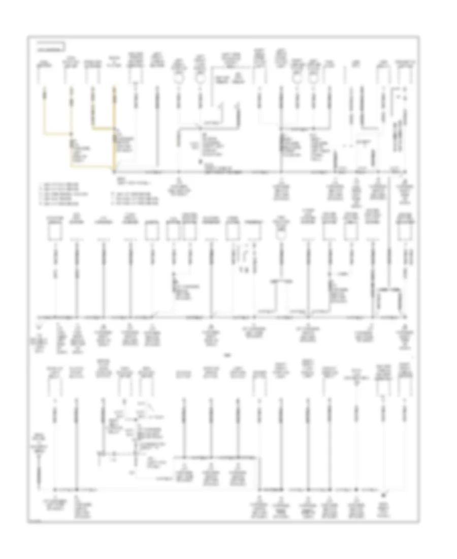
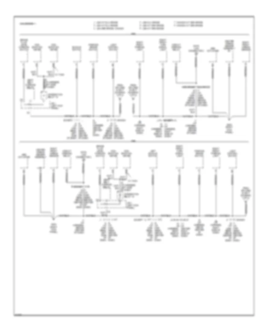
GROUND DISTRIBUTION
Ground Distribution Wiring Diagram (1 of 4) for Toyota T100 1995
List of elements for Ground Distribution Wiring Diagram (1 of 4) for Toyota T100 1995:
- (1995 0nly)
- (1995 m/t only)
- (1995)
- (a/t)
- (i/p harness, above center of dash)
- (left side of engine compt) r/b 2
- 2.7l engine
- A/c amplifier
- A/c switch
- A/t
- A11
- A24
- Abs ecu
- Abs relay
- B10 (body harness, above left rear wheel well)
- Back-up light relay
- Behind left side of dash)
- Blower resistor
- Brake fluid level warning switch
- Buckle switch
- Canada a/t sr5 grade
- Canada m/t sr5 grade
- Center airbag sensor assembly
- Cigarette lighter
- Circuit opening relay
- Clock
- Clutch start switch
- Com- bination meter
- Cruise control actuator
- Cruise control clutch switch
- Cruise control ecu
- Cruise control switch
- D10
- D12
- Data link connector 3 cg
- Dimmer switch
- Efi main relay
- Except
- From splice i4 (diagram 1 of 4)
- Front left side of radiator)
- Fuel pump
- Fuel sender
- G100 (front side of left front fender)
- G200 (left kick panel)
- G203 (right kick panel)
- Heater blower switch
- Heater relay
- High mounted stop light
- I4 (i/p har- ness, left side of dash)
- I4 (i/p harness, left side of dash)
- I5 (i/p harness, left side of dash)
- I6 (i/p harness, above center of dash)
- I6 (i/p harness, center top of dash)
- I7 (i/p har- ness, behind center of dash)
- I7 (i/p harness, behind center of dash)
- I8 (i/p harness, behind center of dash)
- I9 (i/p harness, right side of dash)
- I9 (i/p harness, right side of dash)
- Integration relay 15
- J/b 1 (left kick panel)
- Left front airbag sensor
- Left front parking light
- Left front turn signal light
- Left license plate light
- Left rear combi- nation light
- Light control switch
- M/t
- Noise filter
- O/d main switch
- Parking brake switch
- Radio & player
- Rheostat
- Right front airbag sensor
- Right front parking light
- Right front turn signal light
- Right license plate light
- Right rear combi- nation light
- Seat belt warning relay
- Speaker (woofer)
- Starter relay
- To splice i4 (diagram 1 or 2 of 4)
- Turn signal flasher
- Usa a/t dlx grade
- Usa a/t sr5 grade
- Usa dlx grade
- Usa m/t dlx grade
- Usa m/t sr5 grade
- Usa sr5 grade, canada
- W/ illumination
- W/o illumination
- Wiper and washer switch
Ground Distribution Wiring Diagram (2 of 4) for Toyota T100 1995
List of elements for Ground Distribution Wiring Diagram (2 of 4) for Toyota T100 1995:
- (1995 0nly)
- (1996 2wd)
- (3.4l engine a/t only)
- (3.4l engine only)
- (4wd)
- (front side of left front fender)
- (i/p harness, left side of dash)
- (left side of engine compt) r/b 2
- 1996, 2.7l engine
- 3.4l engine
- A/t 2.7l engine
- A/t 3.4l engine
- Above left front wheel well)
- B16
- Back-up light relay
- Brake fluid level warning switch
- C13
- C14
- C25
- C26
- Canada a/t sr5 grade
- Canada m/t sr5 grade
- Center airbag sensor assembly
- Center airbag sensor assembly e1
- Circuit opening relay
- Clutch start switch
- Com- bination meter
- D10
- D12
- D13
- D24
- D25
- D26
- D33
- D34
- Data link connector 1 cg
- Data link connector 3 cg
- Data link connector 3 sg
- Daytime running light relay
- Daytime running light resistor
- Dimmer switch
- Door lock control ecu
- E01 d13
- E02 d26
- E03
- Efi main relay
- Engine control module
- Except
- From splice i4 (diagram 1 of 4)
- Fuel sender
- G100
- G100 (front side of left front fender)
- G200 (left kick panel)
- G203 (right kick panel)
- Harness, above center
- Harness, behind center of dash)
- Heated oxygen sensor (bank 1 sensor 1)
- Heated oxygen sensor (bank 1 sensor 2)
- Heated oxygen sensor (bank 2 sensor 1)
- Heater relay
- I14 (i/p harness, right kick panel)
- I4 (i/p harness, left side of dash)
- I5 (i/p harness, behind left side of dash)
- I6 (i/p harness, above center of dash)
- I6 i4 (i/p (i/p harness, left side of dash) of dash)
- I7 (i/p (body harness, left door)
- I7 (i/p harness, behind center of dash)
- I8 (i/p harness, behind center of dash) (1995 only)
- I9 (i/p harness, right side of dash)
- Igniter
- Integration relay 15
- J/b 1 (left kick panel)
- Left buckle switch
- Left door key lock & unlock switch
- Left door unlock detection switch
- Left front airbag sensor
- Left front parking lamp
- Left front turn signal lamp
- Left power window master & door lock control switch
- Light control switch
- M/t 2.7l engine
- M/t 3.4l engine
- Parking brake switch
- Radio & player
- Remote control mirror switch
- Right front airbag sensor
- Right front parking light
- Right front turn signal light
- Seat belt warning relay
- Speaker (woofer)
- To splices i5 or i9 (diagram 3 of 4)
- Usa a/t
- Usa a/t dlx grade
- Usa a/t sr5 grade
- Usa dlx grade
- Usa m/t dlx grade
- Usa m/t sr5 grade
- Usa m/t, canada
- Usa sr5 grade, canada
- Vehicle speed sensor
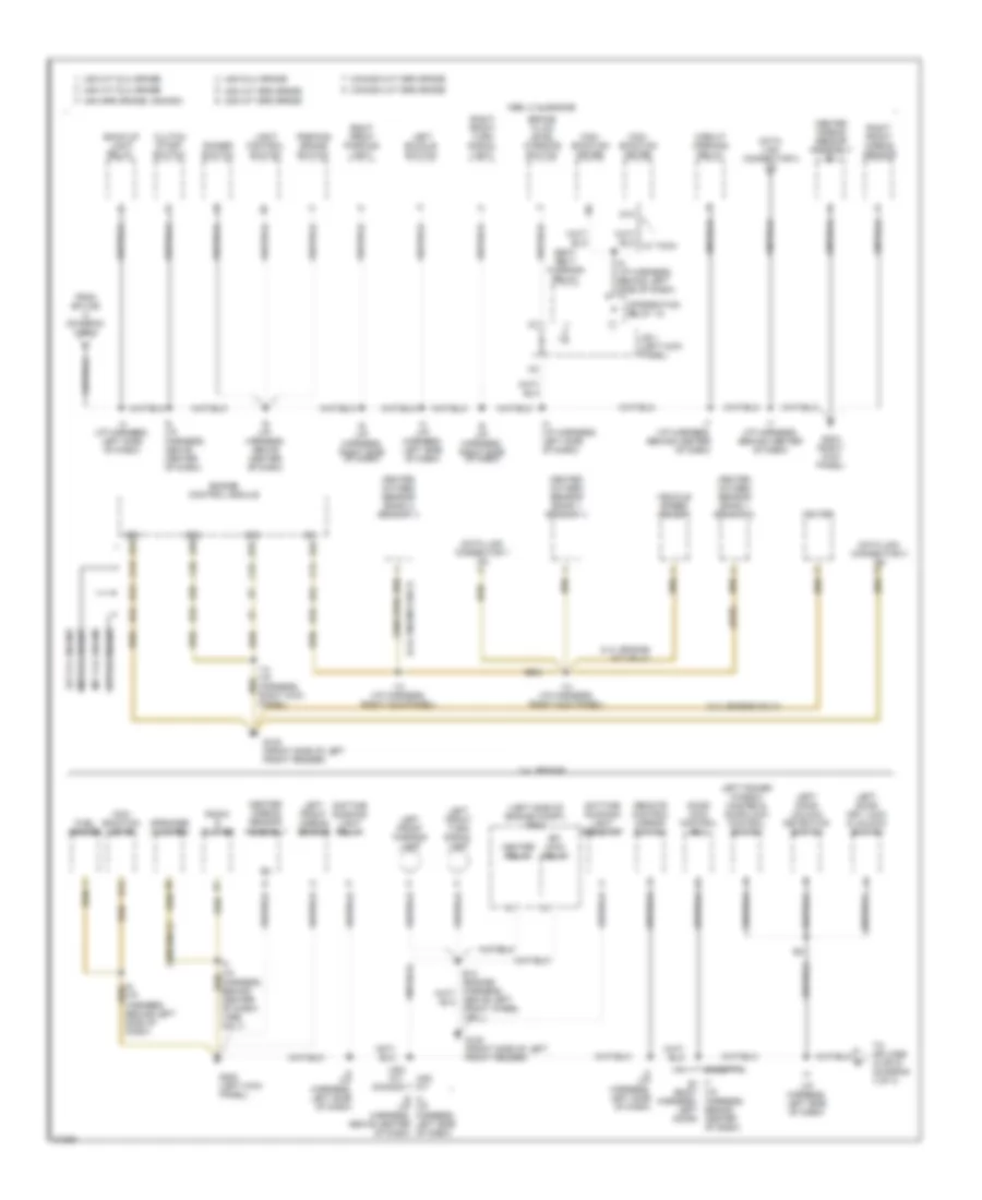
Ground Distribution Wiring Diagram (3 of 4) for Toyota T100 1995
List of elements for Ground Distribution Wiring Diagram (3 of 4) for Toyota T100 1995:
- & 1995
- (1996 only)
- (a/t)
- (canada)
- (i/p
- (i/p har- ness,
- (i/p har- ness, above center of dash)
- (i/p har- ness, left side of dash)
- (i/p harness,
- (i/p harness, above center of dash)
- (i/p harness, behind
- (i/p harness, behind center of dash)
- (m/t)
- 3.4l engine
- 3.4l m/t dlx grade
- A/c amplifier
- A/c switch
- A/t
- A11
- A24
- Above center of dash)
- Abs ecu
- Abs relay
- Auto antenna control relay
- B10 (body harness, above left rear wheel well)
- B11 (body harness, rear side under tailgate)
- B7 (body harness, inside of right door)
- Back-up light relay
- Blower resistor
- Canada a/t sr5 grade
- Canada m/t sr5 grade
- Cigarette lighter
- Clock
- Clutch start cancel switch
- Clutch start switch
- Cruise control actuator
- Cruise control clutch switch
- Cruise control ecu
- Cruise control switch
- Daytime running light relay (main)
- Detection switch (transfer l4 posi- tion, a/t)
- Detection switch (transfer neutral position, a/t)
- Detection switch (transfer position)
- Dimmer switch
- E8 (engine harness, on intake manifolds)
- Except
- From splice i4 b (diagram 2 of 4)
- From splice i9 (diagram 3 of 4)
- Fuel pump
- Glove box light
- Har- ness, above center of dash)
- Har- ness, left side of dash)
- Heater blower switch
- High mounted stop lamp
- I1 (i/p harness, behind left side of dash)
- I1 i6 (i/p har- ness, above center of dash)
- I4 (i/p har- ness, left side of dash)
- I4 (i/p harness,
- I4 i3 (i/p har- ness, left left side of dash) dash)
- I4 i7 (i/p harness, behind left side of dash) center of dash)
- I5 (i/p harness, left side of dash)
- I6 (i/p
- I6 (i/p harness, above center of dash)
- I6 i1 (i/p (i/p har- ness, above center of dash)
- I6 i4 (i/p har- ness, left side of dash)
- I6 i4 (i/p harness, left side of dash)
- I6 i7 (i/p harness, har- ness, behind center of dash)
- I6 i9 (i/p har- har- ness, ness, right side of dash)
- I7 (i/p harness, behind center of dash)
- I7 i4 (i/p harness, left side of center of dash) dash)
- I7 i6 (i/p (i/p har- har- ness, ness, behind center of dash)
- I7 i6 (i/p harness, above center of dash)
- I8 (i/p harness, behind center of dash)
- I9 (i/p har- ness, right side of dash)
- I9 (i/p harness, right side of dash)
- Ignition key cylinder light
- Left license plate light
- Left rear combi- nation light
- Left side of dash)
- M/t
- O/d main switch
- Rheostat
- Right door key lock & unlock switch
- Right door lock control switch
- Right door unlock detection switch
- Right license plate light
- Right rear combi- nation light
- Side of
- Sr5 grade a/t, 3.4l m/t
- Starter relay
- To splices i6 or i7 and i9 (diagram 4 of 4)
- To splices i6 or i9 (diagram 3 of 4)
- Turn signal flasher
- Usa a/t dlx grade
- Usa a/t sr5 grade
- Usa canada
- Usa dlx grade
- Usa m/t dlx grade
- Usa m/t sr5 grade
- Usa m/t, canada usa a/t
- Usa sr5 grade, canada
- Usa, canada canada a/t
- Vcv 2 (add)
- Vcv 4 (add)
- W/ abs w/o abs
- W/ illumination
- W/o illumination
- Washer level sensor
- Wiper and washer switch
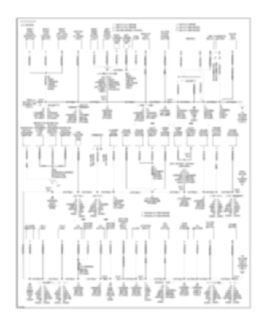
Ground Distribution Wiring Diagram (4 of 4) for Toyota T100 1995
List of elements for Ground Distribution Wiring Diagram (4 of 4) for Toyota T100 1995:
- 3.4l engine
- Above center of dash)
- Abs actuator
- Brake fluid level warning switch
- Buckle switch
- Canada
- Canada a/t sr5 grade
- Canada m/t sr5 grade
- Center airbag sensor assembly
- Center airbag sensor assembly e1
- Circuit opening relay
- Com- bination meter
- D10
- Data link connector 3 cg
- Dlx grade
- Except
- From splices i6 or i7 (diagram 3 of 4)
- G203 (right kick panel)
- Har- ness, left side of dash)
- Harness, right side of dash)
- I5 (i/p harness, left side of dash)
- I6 (i/p har- ness, above center of dash)
- I6 (i/p harness, above center of dash)
- I6 i4 (i/p (i/p har- ness, above center of dash)
- I7 (i/p har- ness, behind center of dash)
- I7 (i/p harness, behind center of dash)
- I7 i6 (i/p (i/p har- har- ness, ness, behind center of dash)
- I9 (i/p harness, right side of dash)
- I9 i11 (i/p (i/p center right side of dash)
- I9 i11 (i/p (i/p harness, right side of dash)
- Integration relay 15
- J/b 1 (left kick panel)
- Left buckle switch
- Light control switch
- M/t
- Parking brake switch
- Right front airbag sensor
- Right front parking light
- Right front turn signal light
- Seat belt warning relay
- Sr5 grade
- Usa a/t dlx grade
- Usa a/t sr5 grade
- Usa dlx grade
- Usa m/t dlx grade
- Usa m/t sr5 grade
- Usa sr5 grade, canada
- W/ tach
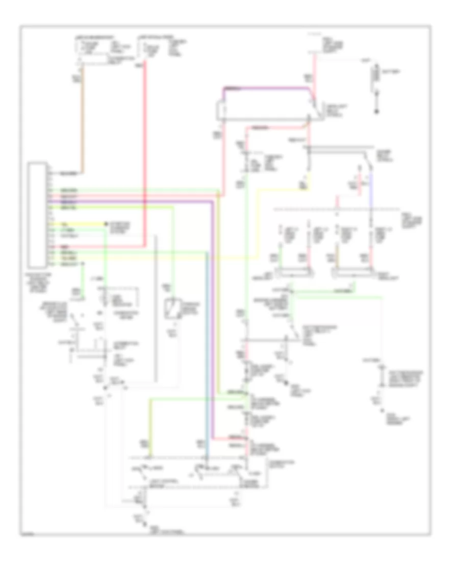
HEADLIGHTS
Headlight Wiring Diagram, with DRL for Toyota T100 1995
List of elements for Headlight Wiring Diagram, with DRL for Toyota T100 1995:
- Battery
- Brake fluid levle switch (left rear of engine compt)
- Combination meter
- Combination switch
- Daytime running light relay 4 (left kick panel)
- Daytime running light resistor (right front of engine compt)
- Dimmer relay (in r/b 2)
- Dimmer switch
- Drl diode 1 (center of i/p)
- Drl diode 2 (center of i/p)
- Drl fuse 7.5a
- E10 (engine harness, left side of battery)
- Ecu-b fuse 15a
- Flash
- Fuse box (left kick panel)
- G100 (front left fender)
- G200 (left kick panel)
- Gauge fuse 10a
- Head
- Headlight relay (in r/b 2)
- High
- High beam indicator
- Hot at all times
- Hot in on or start
- I6 (i/p harness, above center of dash)
- Integration relay
- J/b 1 (left kick panel)
- Left headlight
- Left hi head fuse 10a
- Left lo head fuse 10a
- Light control switch
- Main daytime running light relay (center of dash)
- Off
- Parking brake switch
- R/b 2 (left side of engine compt)
- Red
- Right headlight
- Right hi head fuse 10a
- Right lo head fuse 10a
- Starting/ charging system
- Tail
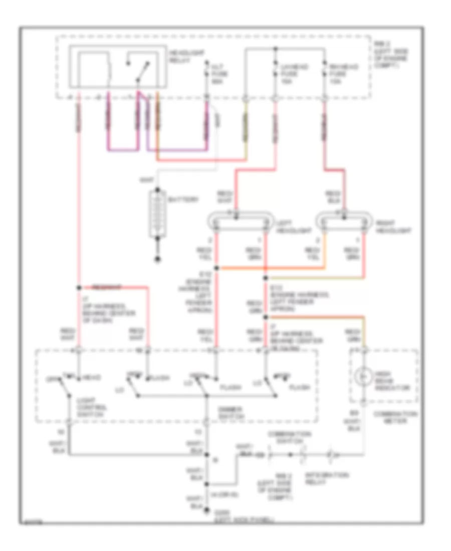
Headlight Wiring Diagram, without DRL for Toyota T100 1995
List of elements for Headlight Wiring Diagram, without DRL for Toyota T100 1995:
- Alt fuse 80a
- Battery
- Combination meter
- Combination switch
- Dimmer switch
- E12 (engine harness, left fender apron)
- Flash
- G200 (left kick panel)
- Head
- Headlight relay
- High
- High beam indicator
- I4 (or i6)
- I7 (i/p harness, behind center of dash)
- Integration relay
- Left headlight
- Lh head fuse 10a
- Light control switch
- Off
- R/b 2 (left side of engine compt)
- Rh head fuse 10a
- Right headlight
- Tail
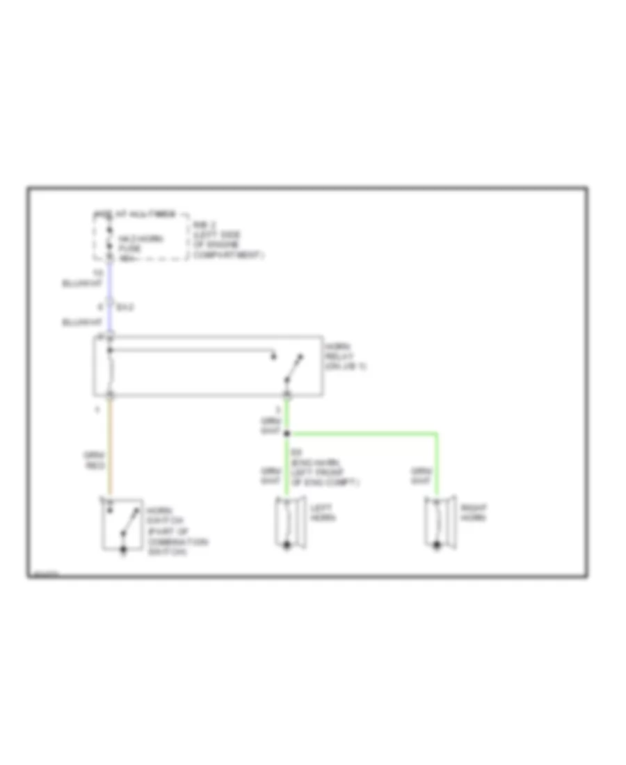
HORN
Horn Wiring Diagram for Toyota T100 1995
List of elements for Horn Wiring Diagram for Toyota T100 1995:
- (part of combination switch)
- E6 (eng harn, left front of eng compt)
- Ea2
- Haz-horn fuse 15a
- Horn relay (on j/b 1)
- Horn switch
- Hot at all times
- Left horn
- R/b 2 (left side of engine compartment)
- Right horn
INSTRUMENT CLUSTER
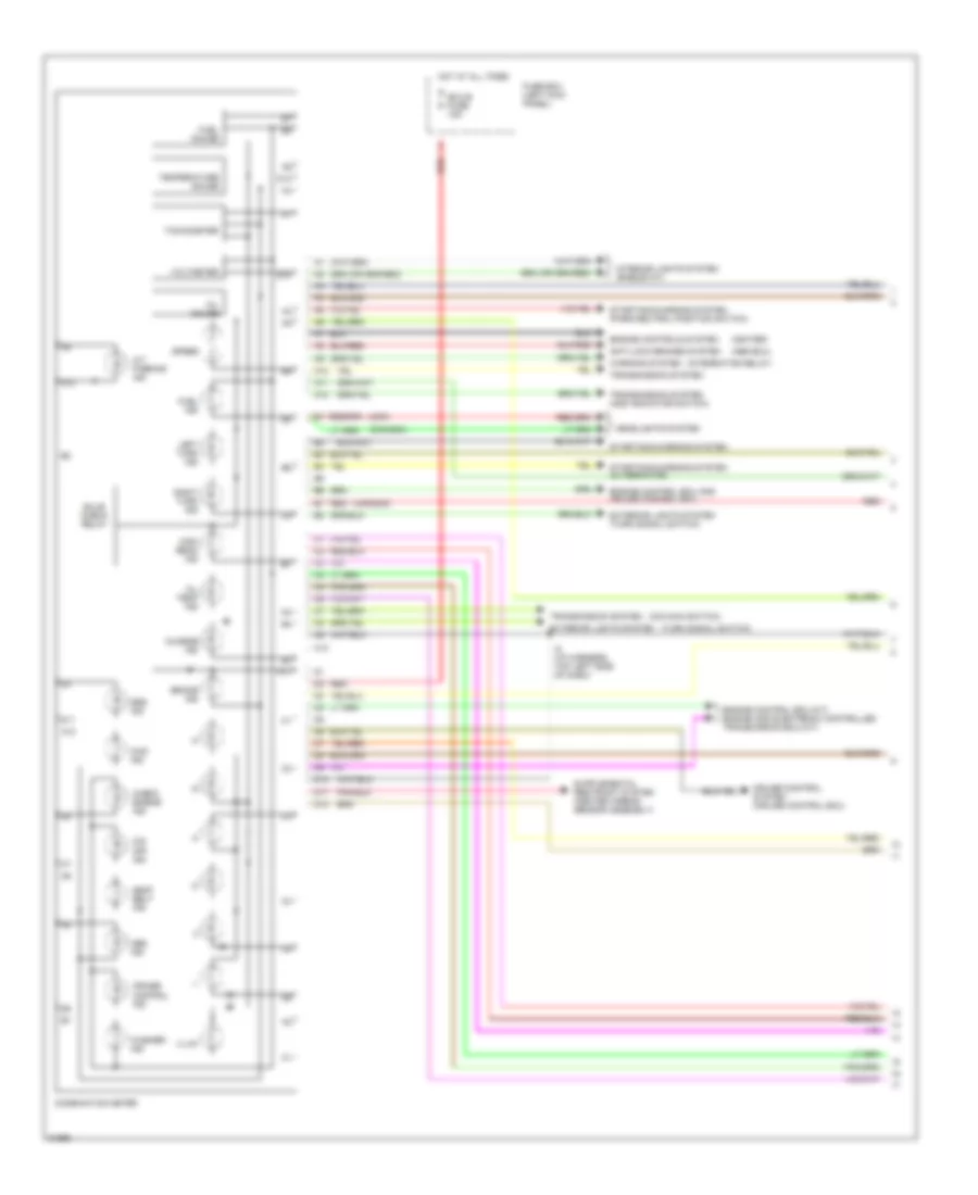
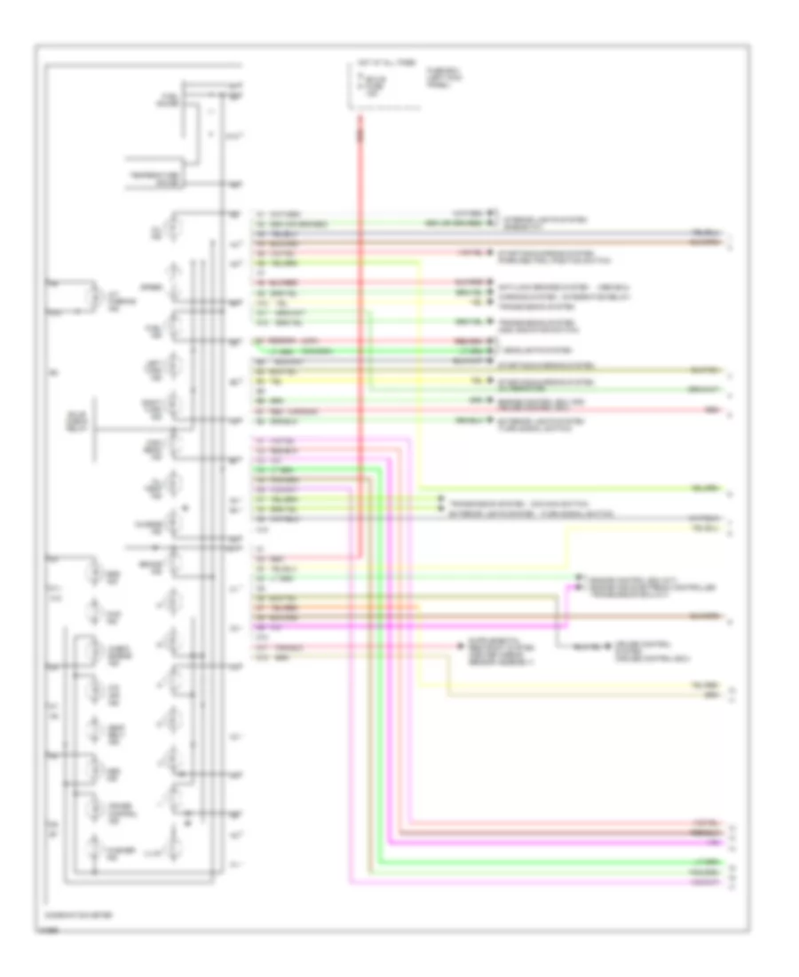
Instrument Cluster Wiring Diagram, with Tach (1 of 2) for Toyota T100 1995
List of elements for Instrument Cluster Wiring Diagram, with Tach (1 of 2) for Toyota T100 1995:
- (abs ecu)
- (canada)
- (igniter)
- (integration relay)
- (o/d main switch)
- (turn signal switch)
- (usa)
- 4wd ind
- A/t parking ind
- A10
- A11
- A12
- Abs ind
- Anti-lock brakes system
- Brake ind
- Bulb check relay
- C10
- Charge ind
- Check engine ind
- Combination meter
- Cruise control ind
- Cruise control system (cruise control ecu)
- D10
- D11
- D12
- Ecu-b fuse 15a
- Engine control ecu (m/t) engine and electronic controlled transmission ecu (a/t)
- Engine control ecu and cruise control ecu
- Engine controls system
- Exterior lights system
- Exterior lights system (turn signal switch)
- Fuel gauge
- Fuel ind
- Fuse box (left kick panel)
- Headlights system
- High beam ind
- Hot at all times
- I5 (i/p harness, top left side of dash)
- Illum
- Interior lights system (rheostat)
- Left turn ind
- O/d off ind
- Oil gauge
- Oil temp ind
- Red
- Right turn ind
- Seat belt ind
- Speed
- Srs ind
- Starting/charging system
- Starting/charging system (alternator)
- Starting/charging system (park/neutral position switch)
- Tachometer
- Temperature gauge
- Transmission system
- Transmission system (add indicator switch)
- Voltmeter
- Warning system
- Washer ind
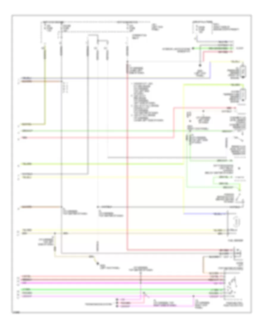
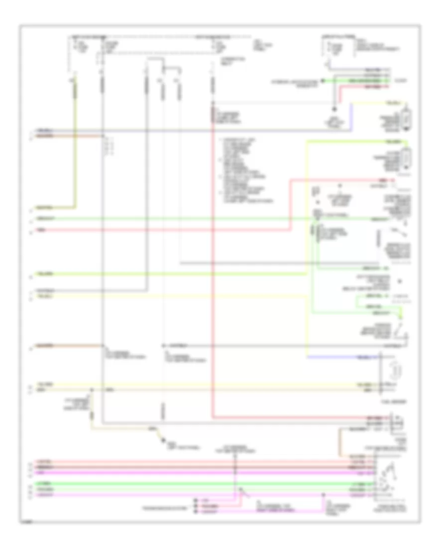
Instrument Cluster Wiring Diagram, with Tach (2 of 2) for Toyota T100 1995
List of elements for Instrument Cluster Wiring Diagram, with Tach (2 of 2) for Toyota T100 1995:
- (i/p harness, top center of dash) i6
- (i/p harness, top left side of dash)
- (usa)
- Brake fluid level switch (brake fluid reservoir)
- Canada m/t, usa m/t sr5 grade (i/p harness, top left end of dash) usa v6 a/t sr5 grade (i/p harness, left side of dash)
- Cig fuse 15a
- Clock
- Daytime running light relay (canada) (below center of dash)
- Diode (a/t) (top center of dash)
- Dome fuse 15a
- Fuel sender
- G200 (left kick panel)
- G203 (right kick panel)
- Gauge fuse 10a
- Hot at all times
- Hot in on and acc
- I1 (i/p harness, left side of dash)
- I12 (i/p harness, right kick panel)
- I5 (canada)
- I5 (i/p harness, top left side of dash)
- I6 (i/p harness, top center of dash)
- I7 (i/p harness, lower left side of dash)
- I9 (i/p harness, top right side of dash)
- Ign fuse 7.5a
- Integration relay
- Interior lights system (rheostat)
- J/b 1 (left kick panel)
- Oil pressure sender (front of engine)
- Park/neutral position switch
- Parking brake switch (behind center of dash)
- R/b 2 (right side of engine compatrment)
- Red
- Transmissions system
- Usa v6 a/t dlx grade, canada i4 a/t (i/p harness, top center of dash) usa m/t dlx grade (i/p harness, lower left side of dash)
- Washer fluid level sensor (canada) (washer fluid reservoir)
- Water temperature sender (rear of engine)
Instrument Cluster Wiring Diagram, without Tach (1 of 2) for Toyota T100 1995
List of elements for Instrument Cluster Wiring Diagram, without Tach (1 of 2) for Toyota T100 1995:
- (abs ecu)
- (canada)
- (integration relay)
- (o/d main switch)
- (turn signal switch)
- (usa)
- 4wd ind
- A/t parking ind
- A10
- A11
- A12
- Abs ind
- Anti-lock brakes system
- Brake ind
- Bulb check relay
- C10
- Charge ind
- Check engine ind
- Combination meter
- Cruise control ind
- Cruise control system (cruise control ecu)
- D10
- D11
- D12
- Ecu-b fuse 15a
- Engine control ecu (m/t) engine and electronic controlled transmission ecu (a/t)
- Engine control ecu and cruise control ecu
- Exterior lights system
- Exterior lights system (turn signal switch)
- Fuel gauge
- Fuel ind
- Fuse box (left kick panel)
- Headlights system
- High beam ind
- Hot at all times
- Illum
- Interior lights system (rheostat)
- Left turn ind
- O/d off ind
- Oil ind
- Oil temp ind
- Red
- Right turn ind
- Seat belt ind
- Speed
- Srs ind
- Starting/charging system
- Starting/charging system (alternator)
- Starting/charging system (park/neutral position switch)
- Temperature gauge
- Transmission system
- Transmission system (add indicator switch)
- Warning system
- Washer ind
Instrument Cluster Wiring Diagram, without Tach (2 of 2) for Toyota T100 1995
List of elements for Instrument Cluster Wiring Diagram, without Tach (2 of 2) for Toyota T100 1995:
- (i/p harness, top center of dash) i6
- (i/p harness, top left side of dash)
- (usa)
- Brake fluid level switch (brake fluid reservoir)
- Canada m/t, usa m/t sr5 grade (i/p harness, top left end of dash) usa v6 a/t sr5 grade (i/p harness, left side of dash)
- Cig fuse 15a
- Clock
- Daytime running light relay (canada) (below center of dash)
- Diode (a/t) (top center of dash)
- Dome fuse 15a
- Fuel sender
- G200 (left kick panel)
- G203 (right kick panel)
- Gauge fuse 10a
- Hot at all times
- Hot in on and acc
- I1 (i/p harness, left side of dash)
- I12 (i/p harness, right kick panel)
- I5 (canada)
- I5 (i/p harness, top left side of dash)
- I6 (i/p harness, top center of dash)
- I7 (i/p harness, lower left side of dash)
- I9 (i/p harness, top right side of dash)
- Ign fuse 7.5a
- Integration relay
- Interior lights system (rheostat)
- J/b 1 (left kick panel)
- Oil pressure sender (front of engine)
- Park/neutral position switch
- Parking brake switch (behind center of dash)
- R/b 2 (right side of engine compatrment)
- Red
- Transmissions system
- Usa v6 a/t dlx grade, canada i4 a/t (i/p harness, top center of dash) usa m/t dlx grade (i/p harness, lower left side of dash)
- Washer fluid level sensor (canada) (washer fluid reservoir)
- Water temperature sender (rear of engine)
INTERIOR LIGHTS
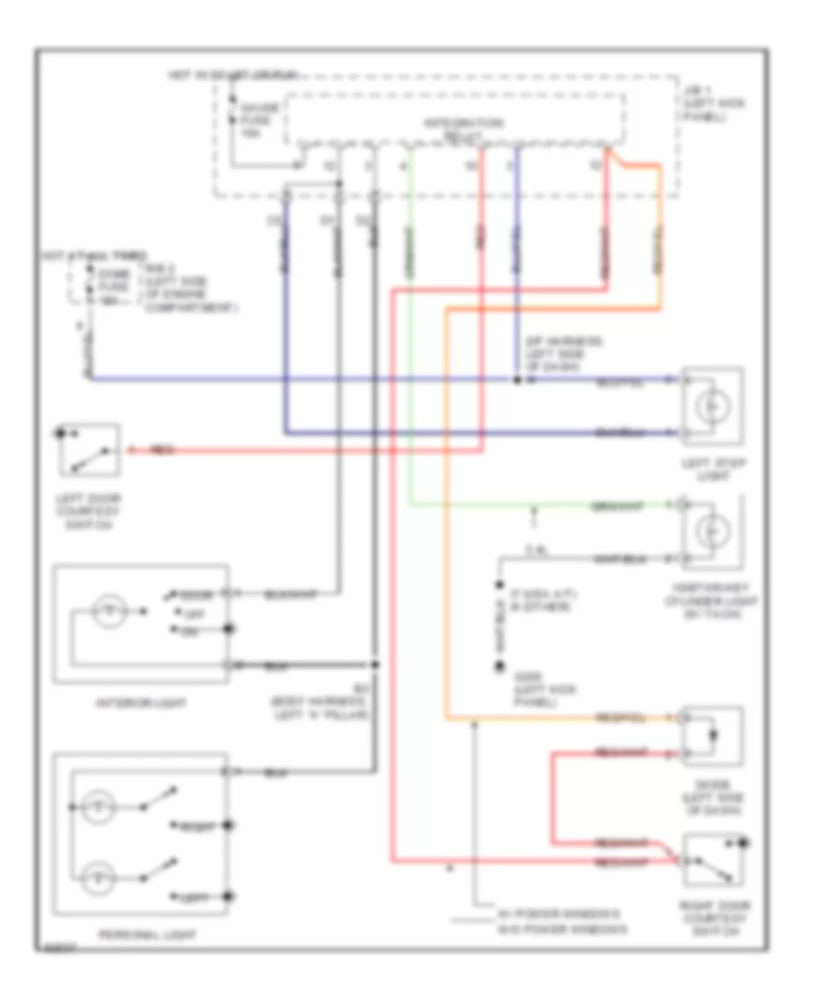
Courtesy Lamps Wiring Diagram for Toyota T100 1995
List of elements for Courtesy Lamps Wiring Diagram for Toyota T100 1995:
- (i/p harness, left side of dash) i4
- 3.4l
- B2 (body harness, left "a" pillar)
- Diode (left side of dash)
- Dome fuse 15a
- Door
- G200 (left kick panel)
- Gauge fuse 10a
- Hot at all times
- Hot in start or run
- I7 (usa a/t) i6 (other)
- Ignition key cylinder light (w/ tach)
- Integration relay
- Interior light
- J/b 1 (left kick panel)
- Left
- Left door courtesy switch
- Left step light
- Off
- Personal light
- R/b 2 (left side of engine compartment)
- Red
- Right
- Right door courtesy switch
- W/ power windows
- W/o power windows
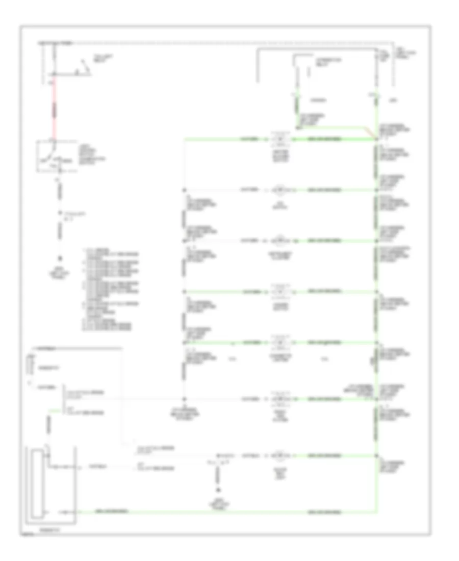
Instrument Illumination Wiring Diagram for Toyota T100 1995
List of elements for Instrument Illumination Wiring Diagram for Toyota T100 1995:
- (i/p harness, behind center of dash) i7
- (i/p harness, behind center of dash) i8
- (i/p harness, left side of dash) i4
- (i/p harness, left side of dash) i4 (2.7l)
- (i/p harness, left side of dash) i4 (3.4l)
- 2.7l (3rz-fe) 3.4l (5vz-fe) a/t sr5 grade canada 3.4l (5vz-fe) m/t sr5 grade 3.4l (5vz-fe) dlx grade 3.4l (5vz-fe) a/t sr5 grade 3.4l (5vz-fe) dlx grade canada 3.4l (5vz-fe) m/t sr5 grade 3.4l (5vz-fe) sr5 grade
- 3.4l
- 3.4l (5vz-fe) m/t dlx grade 2.7l (3rz-fe) canada 3.4l (5vz-fe) a/t dlx grade sr5 grade
- 3.4l m/t dlx grade 2.7l m/t
- A/c switch
- A/t 3.4l m/t sr5 grade
- C14
- Canada
- Cigarette lighter
- G200 (left kick panel)
- Glove box light
- Hazard switch
- Head
- Heater blower switch
- Hot at all times
- I4 (2.7l)
- I4 (i/p harness, left side of dash)
- I6 (2.7l)(canada) (i/p harness, above center of dash)
- I6 (3.4l) (i/p harness, above center of dash)
- I6 (i/p harness, above center of dash)
- I7 (3.4l m/t)
- I8 (i/p harness, behind center of dash)
- Instrument cluster
- Integration relay
- J/b 1 (left kick panel)
- Light control switch (combination switch)
- M/t dlx grade canada a/t dlx grade 3.4l (5vz-fe) sr5 grade 3.4l (5vz-fe) dlx grade
- Off
- Radio and player
- Rheostat
- Tail
- Tail fuse 15a
- Taillight relay
- Usa
POWER ANTENNA
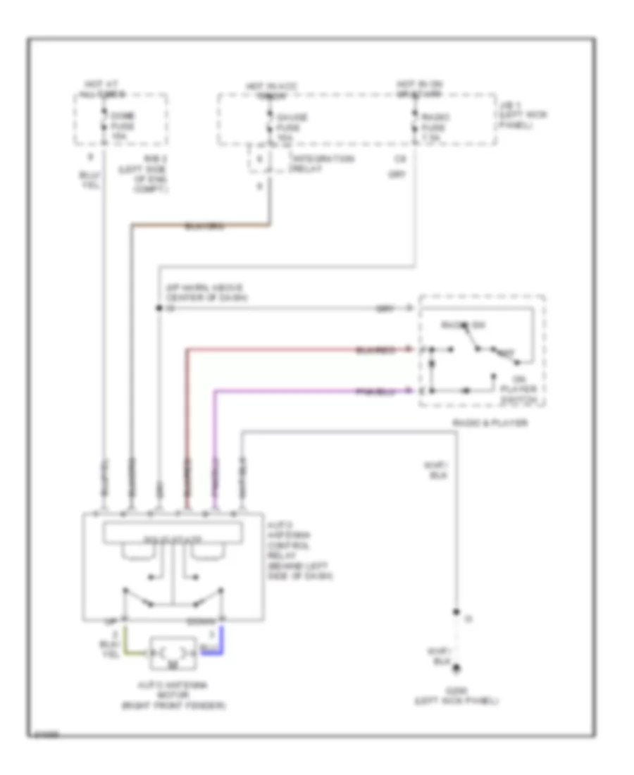
Power Antenna Wiring Diagram for Toyota T100 1995
List of elements for Power Antenna Wiring Diagram for Toyota T100 1995:
- (i/p harn, above center of dash) i3
- Auto antenna control relay (behind left side of dash)
- Auto antenna motor (right front fender)
- Dome fuse 15a
- Down
- G200 (left kick panel)
- Gauge fuse 10a
- Hot at all times
- Hot in acc or on
- Hot in on or start
- Integration relay
- J/b 1 (left kick panel)
- Off
- On player switch
- R/b 2 (left side of eng compt)
- Radio & player
- Radio fuse 7.5a
- Radio sw
- Solid state
POWER DISTRIBUTION
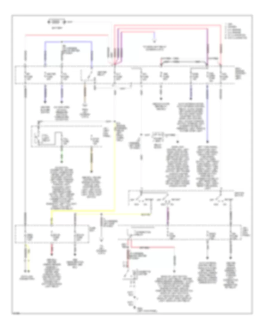
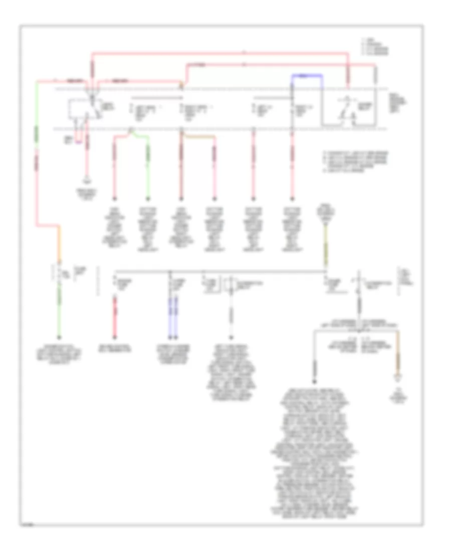
Power Distribution Wiring Diagram (1 of 2) for Toyota T100 1995
List of elements for Power Distribution Wiring Diagram (1 of 2) for Toyota T100 1995:
- (1995)
- (1996)
- 2.7l engine
- 3.4l engine
- 40a
- A/c amplifier, a/c dual pressure switch & thermister, a/c switch
- A/c fuse 10a
- A/c switch, cigarette lighter, clock, combination meter, left door courtesy switch, left front parking light, right front parking light, glove box light, hazard switch, heater blower switch, left license plate light, right license plate light, radio & player, rheostat, left taillight, right taillight, integration relay
- Abs actuator, abs relay, abs ecu
- Abs deceleration sensor, abs ecu
- Abs ecu, center airbag sensor assembly, combination meter, srs warning light, cruise control ecu, data link connector 1, daytime running light relay
- Abs ecu, cruise control ecu, engine control module, high mounted stop light, left stop light, right stop light, stop light switch
- Abs fuse 60a
- Acc
- Alt fuse 80a
- Am1 fuse
- Am2 fuse 30a
- Auto antenna control relay, radio & player, left remote control mirror, right remote control mirror, remote control mirror switch
- Auto antenna motor, auto antenna control relay, clock, diode, left door courtesy switch, right door courtesy switch, door lock control ecu, unlock warning switch, interior light, integration relay, personal light, radio & player, step light
- Back-up light switch, back-up light relay, center airbag sensor assembly, clock, a/t parking indicator light, a/t indicator light, diode, engine control module, park neutral position switch, back-up light switch & a/t indicator switch, left back-up light, right back-up light, back-up light relay
- Battery
- Canada
- Center airbag sensor assembly, charge warning light, combination meter, generator, efi relay
- Cig fuse 15a
- Cigarette lighter
- Data link connector 3
- Dome fuse 15a
- Door lock control ecu, left door lock motor, left door unlock detection switch, left door key lock & unlock switch, right door lock motor, right door unlock detection switch, left power window master switch & door lock control switch, left power window motor, right power window motor
- E12 (engine harness, above left front wheel well)
- E6 (i/p harness, above center of dash)
- Ecu-b fuse 15a
- Ecu-ig fuse 20a
- Efi fuse 15a
- From j/b 1 (diagram 2 of 2)
- Fuse box
- G200 (left kick panel)
- Haz- horn fuse 15a
- Heater blower switch
- Heater fuse 40a
- Heater relay
- I4 (i/p harness, left side of dash)
- I7 (i/p harness, behind center of dash)
- Ign fuse 7.5a
- Ignition switch
- Integration relay
- J/b 1 (left kick panel)
- Left turn signal indicator light, right turn signal indicator light, turn signal switch, horn switch, left front turn signal light, right front turn signal light, left horn, right horn, hazard switch, horn relay, integration relay, left rear turn signal light, right rear turn signal light
- Nca
- Obd2 fuse 7.5a
- Off
- Power 30a
- R/b 2 (engine compart- ment left)
- Radio fuse 7.5a
- Red
- Relay block
- Start
- Stop fuse 15a
- Tail fuse 15a
- Tail- light relay
- To headlight relay (diagram 2 of 2)
- To j/b 1 (diagram 2 of 2)
- Usa
- W/ illumination
- W/o illumination
Power Distribution Wiring Diagram (2 of 2) for Toyota T100 1995
List of elements for Power Distribution Wiring Diagram (2 of 2) for Toyota T100 1995:
- (i/p harness, left side of dash) i4
- (i/p harness, left side of dash) i5
- 2.7l engine
- 3.4l engine
- A canada m/t, usa m/t sr5 grade
- Abs actuator, abs relay, add indicator switch (w/add) or short pin (w/o add), abs ecu, add control relay, auto antenna control relay, back-up light switch, brake fluid level
- B usa 3.4l engine a/t sr5 grade
- C usa 3.4l engine a/t dlx grade, canada a/t, 2.7l engine
- C15
- C16
- Canada
- Cruise control ecu, generator
- D usa m/t dlx grade
- Daytime running light resistor, daytime running light relay no 4, left headlight
- Daytime running light resistor, daytime running light relay no 4, right headlight
- Dimmer relay
- Dimmer switch, light control switch, daytime running light relay no 4, diode no 1, diode no 2
- Drl 7.5a
- Engine fuse 10a
- From r/b 2 (diagram 1 of 2)
- From splice i4 (diagram 1 of 2)
- Fuse box
- Gauge fuse 10a
- Head relay
- High beam indicator light, dimmer switch, left headlight, integration relay
- High beam indicator light, dimmer switch, right headlight, integration relay
- I6 (i/p harness, above center of dash)
- I7 (i/p harness, behind center of dash)
- Integration relay
- J/b 1 (left kick panel)
- Left head left hi head 10a
- Left lo head 10a
- Left turn signal indicator light, right turn signal indicator light, turn signal switch, left front turn signal light, right front turn signal light, hazard switch, integration relay, left rear turn signal light, right rear turn signal light, turn signal flasher, integration relay
- Light, a/t parking indicator light, combination meter, seat belt warning light, 4wd indicator light, a/t indicator light, cruise control indicator light, malfunction indicator lamp, o/d off indicator light, cruise control ecu, data link connector 1, detection switch (transfer neutral position, a/t), detection switch transfer position), main daytime running light relay, diode (a/t), door lock control ecu, engine control module, fuel sender, heater blower switch, integration relay, oil pressure sender, o/d main switch, park neutral position switch, back-up light switch & a/t indicator switch, parking brake switch, left back-up light, right back-up light, vsv 2 (add), vsv 4 (add), washer level sensor, water temperature sender, heater relay (coil side), back-up light relay (coil side), back-up light relay (point side)
- R/b 2 (engine compart- ment left)
- Red
- Right head right hi head 10a
- Right lo head 10a
- To r/b 2 (diagram 1 of 2)
- Turn fuse 10a
- Usa
- Warning switch, back-up light relay (coil side), back-up light relay (point side), abs warning
- Wiper & washer switch, washer level sensor, washer motor, wiper motor
- Wiper fuse 20a
POWER DOOR LOCKS
Power Door Lock Wiring Diagram for Toyota T100 1995
List of elements for Power Door Lock Wiring Diagram for Toyota T100 1995:
- B2 (body harn, inside right door)
- B2 (body harn, left "a" pillar)
- Dome fuse 15a
- Door lock control relay (left side of i/p)
- G200 (left kick panel)
- Hot at all times
- I6 (usa a/t) i4 (except usa a/t)
- I6 (usa a/t) i4 (except usa a/t) (i6-i/p harn, center of dash) (i4-i/p harn, left side of dash)
- I9 (1995) i4 (1996-97) (i/p harn, left side of dash-1996-97) (i/p harn, left side of dash-1995)
- I9 (1995) i4 (1996-97) (i/p harn, left side of dash-1996-97) (i/p harn, left side of dash-1995)
- Left door courtesy switch
- Left door key lock/unlock switch
- Left door lock control switch (power window master switch)
- Left door lock motor/ unlock detection switch
- Lock
- Lock timer
- Power fuse 30a
- R/b 2 (left side of engine compartment)
- Red
- Relay block (left kick panel)
- Right door courtesy switch
- Right door key lock/unlock switch
- Right door lock control switch
- Right door lock motor/ unlock detection switch
- Solid state
- Unlock
- Unlock timer
- Unlock warning switch (ignition switch)
POWER MIRRORS
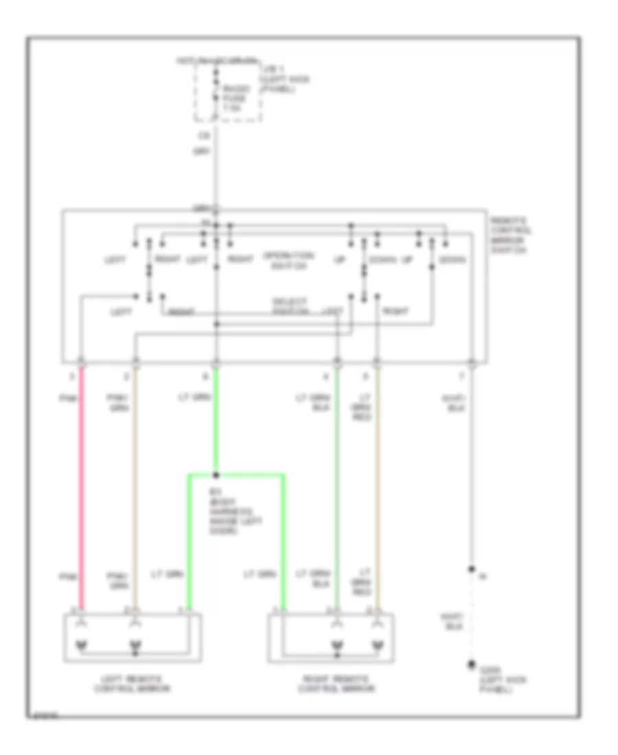
Power Mirror Wiring Diagram for Toyota T100 1995
List of elements for Power Mirror Wiring Diagram for Toyota T100 1995:
- B3 (body harness, inside left door)
- Down
- G200 (left kick panel)
- Hot in acc or on
- J/b 1 (left kick panel)
- Left
- Left remote control mirror
- Operation switch
- Pnk
- Radio fuse 7.5a
- Remote control mirror switch
- Right
- Right remote control mirror
- Select switch
POWER WINDOWS
Power Window Wiring Diagram for Toyota T100 1995
List of elements for Power Window Wiring Diagram for Toyota T100 1995:
- (1996-98) b1 i2 (1995) (usa a/t) (dash harness, under steering column)
- (body harness, left kick panel) (except usa a/t) b1
- (dash harn, left side of dash) i4
- (dash harness, top center of dash) i6
- (dash harness, under steering column) (except usa a/t) i7
- (usa a/t) (body harness, left kick panel)
- Diode (power window) (under top left side of dash)
- Door lock control ecu (at left kick panel)
- Down
- Driver's
- G200 (left kick panel)
- Gauge fuse 10a
- Hot at all times
- Hot in on or start
- I4 (dash harness, left side of dash)
- I6 (usa a/t) (dash harness, top center of dash)
- Integration relay
- J/b 1 (at left kick panel)
- Left door courtesy switch (at base of left "a" pillar)
- Left power window motor
- Lock
- Normal
- Passenger's
- Power fuse 30a
- Power window master switch
- Red
- Relay block (at left kick panel)
- Right door courtesy switch (at base of right "b" pillar)
- Right power window control switch
- Right power window motor
- Solid state
- Window lock switch
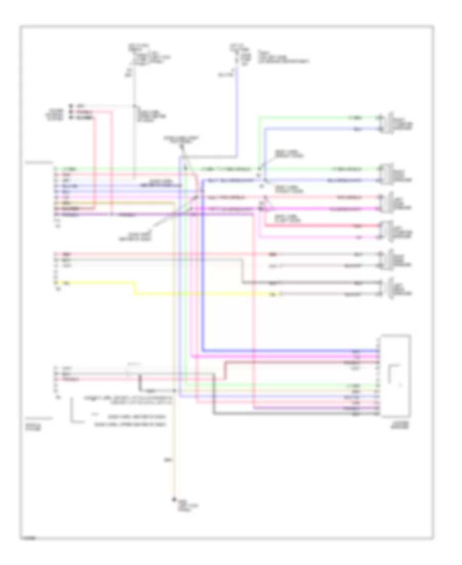
RADIO
Radio Wiring Diagrams for Toyota T100 1995
List of elements for Radio Wiring Diagrams for Toyota T100 1995:
- (body harn, in left door)
- (body harn, in right door)
- (dash harn, center of dash)
- (dash harn, center of dash) i8
- (dash harn, right kick panel) i12
- (dash harn, upper center of dash)
- (usa 6cyl m/t dlx & all 4cyl) i8
- (usa 6cyl sr5, usa 6cyl a/t dlx & canada) i6
- Dome fuse 15a
- G200 (left kick panel)
- Hot at all times
- Hot in acc or run
- I8 (dash harn, center of dash)
- J/b 1 (left kick panel)
- Left door speaker
- Left rear speaker
- Left tweeter speaker
- Nca
- Pnk
- Power antenna system
- R/b 2 (on left side of engine compartment)
- Radio & player
- Radio fuse 7.5a
- Red
- Right door speaker
- Right rear speaker
- Right tweeter speaker
- Woofer speaker
STARTING/CHARGING
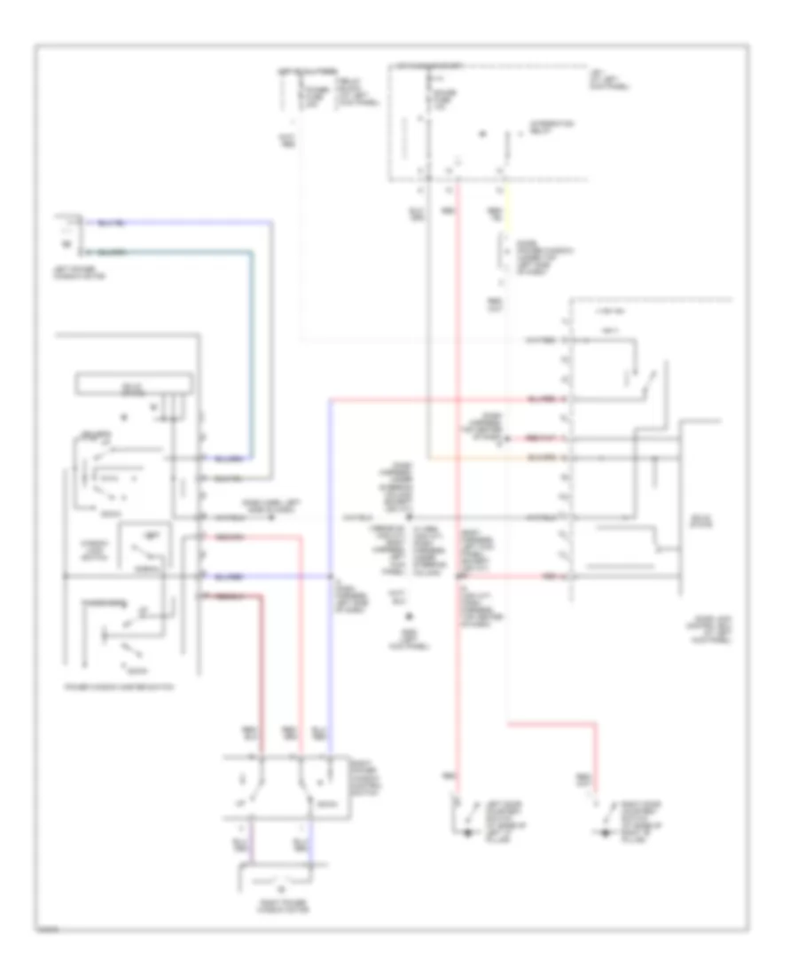
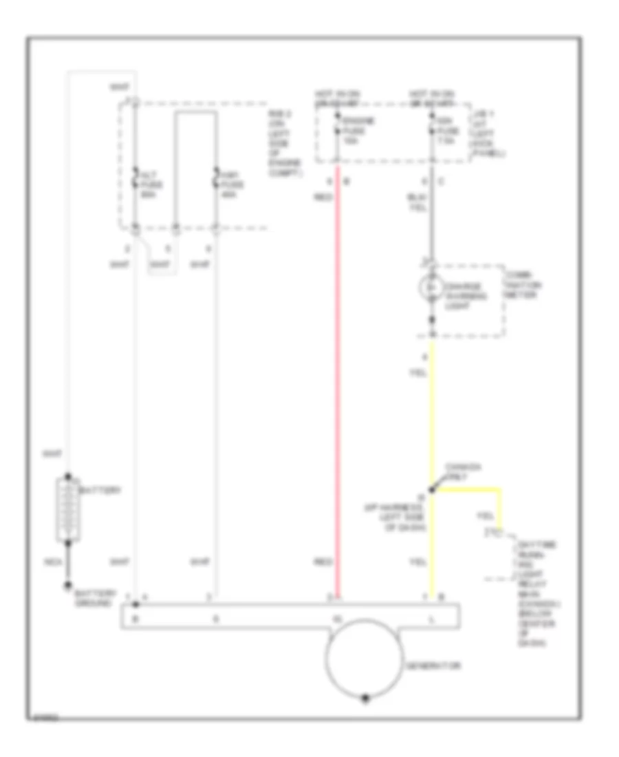
Charging Wiring Diagram for Toyota T100 1995
List of elements for Charging Wiring Diagram for Toyota T100 1995:
- Alt fuse 80a
- Am1 fuse 40a
- Battery
- Battery ground
- Canada only
- Charge warning light
- Comb- ination meter
- Daytime runn- ing light relay main (canada) (below center of dash)
- Engine fuse 10a
- Generator
- Hot in on or start
- I5 (i/p harness, left side of dash)
- Ign fuse 7.5a
- J/b 1 (at left kick panel)
- Nca
- R/b 2 (on left side of engine compt)
- Red
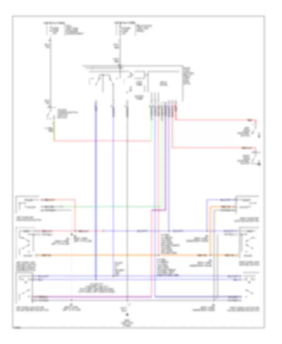
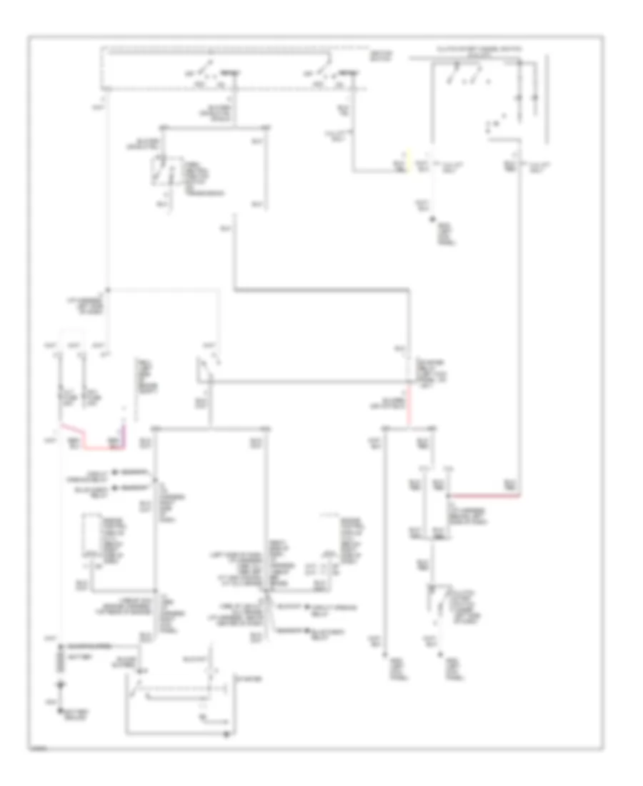
Starting Wiring Diagram for Toyota T100 1995
List of elements for Starting Wiring Diagram for Toyota T100 1995:
- (1996-97) e16 (engine harness, top rear of engine)
- (a/t)
- (m/t)
- (right side of dash, (left side of dash, i/p harness) (1995: all; 1996-1997: a/t and canada, m/t dlx grade) i4
- 2.7l
- 3.4l
- 3.4l m/t only
- A/t
- Acc
- Alt fuse 80a
- Am1 fuse 40a
- Battery
- Battery ground
- Bulb check relay
- Circuit opening relay
- Clutch start cancel switch (3.4l m/t)
- Clutch start switch (under left side of dash)
- Engine control module (2.7l) (below right side of dash)
- Engine control module (3.4l) (below right side of dash)
- G200 (left kick panel)
- I/p harness) (1996-97 sr5 grade) i9
- I14 (1995) (i/p harness, right kick panel)
- I3 (i/p harness, behind left side of dash)
- I4 (i/p harness, left side of dash)
- I6 (1996, 97 usa m/t dlx grade) (i/p harness, above center of dash)
- I9 (i/p harness, right side of dash)
- Ignition switch
- M/t
- Nca
- Off
- P/ n
- Park/ neutral position switch (on transmission)
- R/b 2 (left side of engine compt)
- Sta
- Start
- Starter
- Starter relay (left kick panel, on j/b 1)
SUPPLEMENTAL RESTRAINTS
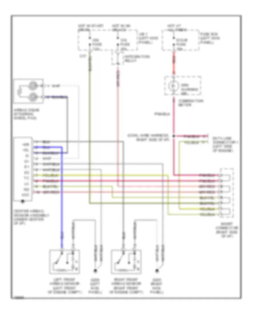
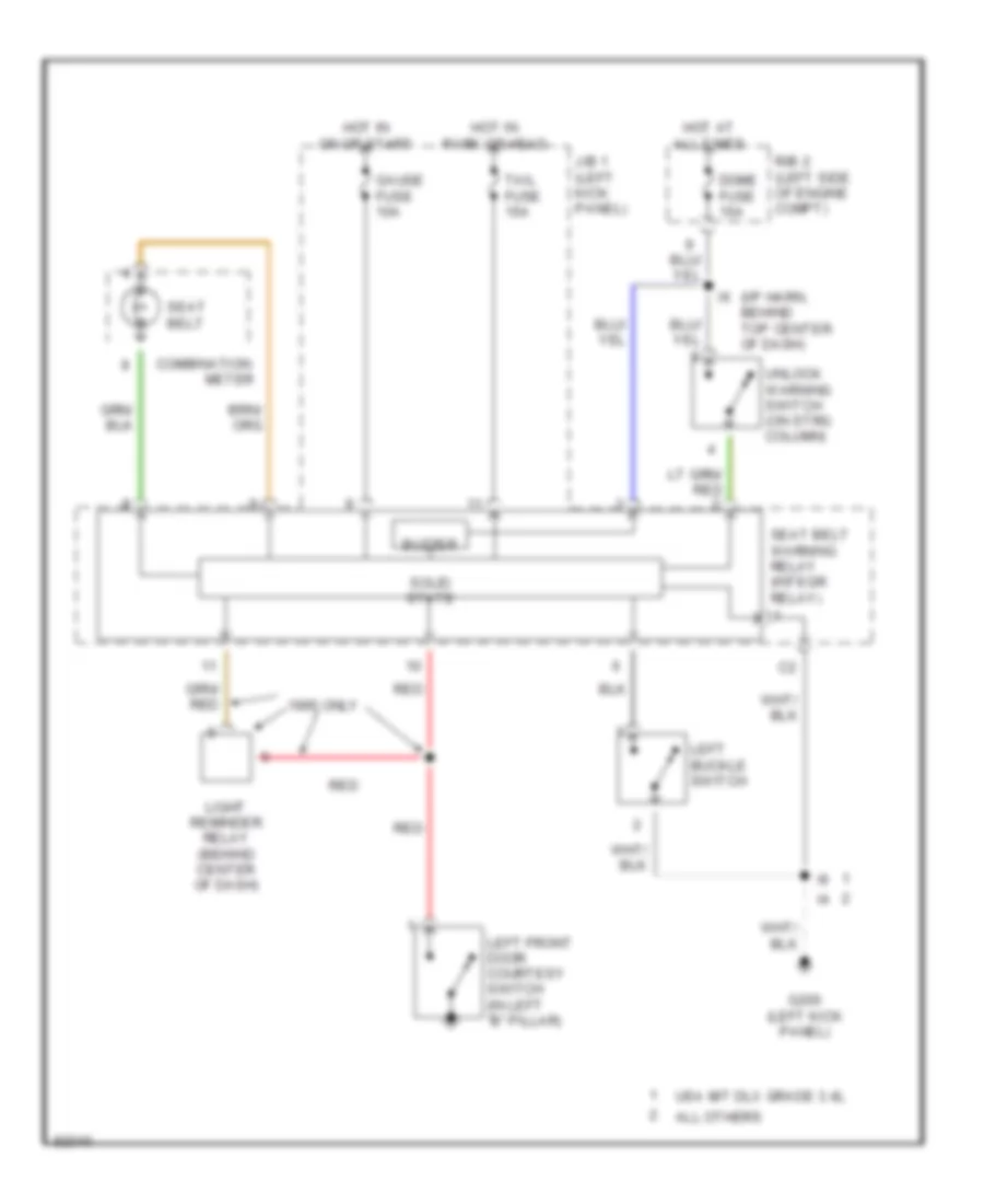
Supplemental Restraint Wiring Diagram for Toyota T100 1995
List of elements for Supplemental Restraint Wiring Diagram for Toyota T100 1995:
- (cowl wire harness, right side of i/p)
- (left front of engine compt)
- (right front of engine compt)
- +sl
- +sr
- Acc
- Airbag squib (steering wheel pad)
- C17
- Center airbag sensor assembly (under center of i/p)
- Cig fuse 15a
- Combination meter
- Data link connector 1 (left side of engine)
- Ecu-b fuse 15a
- Fuse box (left kick panel)
- G200 (left kick panel)
- G203 (right kick panel)
- Hot at all times
- Hot in on or acc
- Hot in start or on
- Ig2
- Ign fuse 7.5a
- Integration relay
- J/b 1 (left kick panel)
- Left front airbag sensor
- Red
- Right front airbag sensor
- Short connector (right side of i/p)
- Srs warning ind
TRANSMISSION
2.7L
2.7L, Transmission Wiring Diagram for Toyota T100 1995
List of elements for 2.7L, Transmission Wiring Diagram for Toyota T100 1995:
- (1996 only)
- A/t indicator (p/n position) switch (under central trans tunnel)
- A/t oil temperature sensor (on transmission)
- Batt (b+)
- C17
- Cig fuse 15a
- Computer data lines system
- Conn a
- Conn b
- Conn c
- Conn d
- Cruise control system
- Diode (behind right dash)
- E1 (grd)
- Efi fuse 15a
- Efi main
- Electronic controlled transmission solenoids
- Engine control module (right kick panel)
- Engine coolant temperature sensor (on engine)
- G100 (front of left front fender)
- G110 (left front of engine)
- G200 (left kick panel)
- Gauge fuse 10a
- Hot at all times
- Hot in acc or run
- Hot in run or start
- I12
- I12 (i/p harn, right kick panel)
- I14
- I14 (i/p harn, right kick panel)
- I4 (i/p harness, left side of dash)
- Idl
- Ign fuse 7.5a
- Instrument cluster system
- Integration relay
- J/b 1 (left kick panel)
- Nca
- No. 1
- No. 2
- No. 3
- O/d main switch
- Od2
- Oil
- R/b 2 (left side of engine compt)
- Red
- Relay
- Sp1
- Sp2+
- Sp2-
- Stop fuse 10a
- Stoplamp switch (brake pedal bracket)
- Te1
- Throttle position sensor (on throttle body)
- Thw
- Vcc
- Vehicle speed sensor (for ect) (on transmission)
- Vta
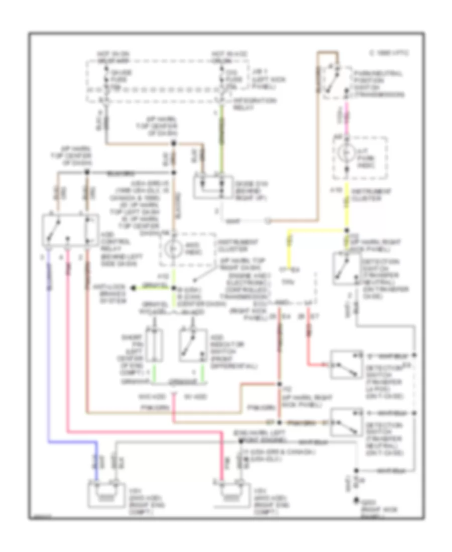
Transfer Case Wiring Diagram, A/T for Toyota T100 1995
List of elements for Transfer Case Wiring Diagram, A/T for Toyota T100 1995:
- (behind left side dash)
- (eng harn, left front engine)
- (i/p harn, right kick panel)
- (i/p harn, top center of dash)
- (i/p harn, top right dash)
- (left kick panel)
- (usa-sr5) i5 (1995 usa-dlx, i6
- 4wd
- 4wd indic.
- A/t park indic.
- A10
- A12
- Add control relay
- Add indicator switch (front differential)
- Anti-lock brakes system
- C 1995 vftc
- Canada & 1996) (i5: i/p harn, top left dash i6: i/p harn, top center dash)
- Cig fuse 15a
- Detection switch (transfer l4 pos) (on t-case)
- Detection switch (transfer neutral) (on t-case)
- Detection switch (transfer neutral) (on transfer case)
- Diode d10 (behind right i/p)
- Engine and electronic controlled transmission ecu (right kick panel)
- G203 (right kick panel)
- Gauge fuse 10a
- Hot in acc or on
- Hot in on or start
- I1 (usa-sr5 & canada) i6 (usa-dlx)
- I12
- I9 (usa) i6 (can) (center dash)
- Instrument cluster
- Integration relay
- J/b 1
- Park/neutral position switch (transmission)
- Pnk
- Red
- Short pin (left center of eng compt)
- Tfn
- Vsv (2wd add) (right eng compt)
- Vsv (4wd add) (right eng compt)
- W/ add
- W/o add
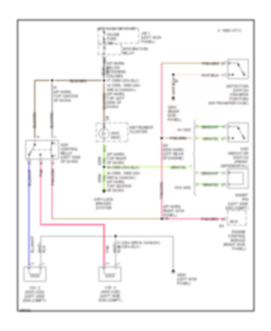
Transfer Case Wiring Diagram, M/T for Toyota T100 1995
List of elements for Transfer Case Wiring Diagram, M/T for Toyota T100 1995:
- (i/p harn, below steering column)
- (i/p harn, right kick panel) i12
- 4wd
- 4wd indic.
- A12
- Add control relay (left side of dash)
- Add indicator switch (front differential)
- Anti-lock brakes system
- C 1995 vftc
- Detection switch (tranfer position) (on transfer case)
- E8 (eng harn, left rear of engine)
- Engine control module (right kick panel)
- G200 (left kick panel)
- G203 (right kick panel)
- Gauge fuse 10a
- Hot in on or start
- I1 (usa-sr5 & canada) i6 (usa-dlx)
- I6 (1995, 1996 usa- sr5 & canada) (i/p harn, top center of dash)
- I6 (i/p harn, top center of dash)
- I7 (1996 usa-dlx)
- I9 (1996 usa-dlx)
- Instrument cluster
- Integration relay
- J/b 1 (left kick panel)
- Of dash)
- Pnk
- Short pin (left side eng compt)
- Top left side of dash)
- Vsv 2 (2wd add) (left side eng compt)
- Vsv 4 (4wd add) (left side eng compt)
- W/ add
- W/o add
3.4L
3.4L, Transmission Wiring Diagram for Toyota T100 1995
List of elements for 3.4L, Transmission Wiring Diagram for Toyota T100 1995:
- 4wd
- A/t indicator (p/n position) switch (under central trans tunnel)
- A/t oil temperature sensor (on transmission)
- Add indicator switch or add jumper pin (left rear of engine compt)
- Batt (b+)
- C17
- Cig fuse 15a
- Computer data lines system
- Conn a
- Conn b
- Conn c
- Conn d
- Cruise control system
- Diode (behind right dash)
- E1 (grd)
- E7 (engine harn, left front of engine)
- Efi fuse 15a
- Efi main
- Electronic controlled transmission solenoids
- Engine control module (right kick panel)
- Engine coolant temperature sensor (on engine)
- G100 (front of left front fender)
- G110 (left front of engine)
- G200 (left kick panel)
- Gauge fuse 10a
- Hot at all times
- Hot in acc or run
- Hot in run or start
- I14
- I14 (i/p harness, right kick panel)
- I5 (or i6)
- I5 (or i7) (i/p harn, left side of dash)
- Idl
- Ign fuse 7.5a
- Instrument cluster system
- Integration relay
- J/b 1 (left kick panel)
- Nca
- No. 1
- No. 2
- No. 3
- O/d main switch
- Od1
- Od2
- Oil
- Oilw
- R/b 2 (left side of engine compt)
- Red
- Relay
- Sp2
- Spd
- Stop fuse 10a
- Stoplamp switch (brake pedal bracket)
- Te1
- Throttle position sensor (on throttle body)
- Thw
- Transfer case position detection switch (transfer case)
- Transfer l4 position detection switch (transfer case)
- Vcc
- Vehicle speed sensor (for ect) (on transmission)
- Vta
Transfer Case Wiring Diagram, A/T for Toyota T100 1995
List of elements for Transfer Case Wiring Diagram, A/T for Toyota T100 1995:
- (behind left side dash)
- (eng harn, left front engine)
- (i/p harn, right kick panel)
- (i/p harn, top center of dash)
- (i/p harn, top right dash)
- (left kick panel)
- (usa-sr5) i5 (1995 usa-dlx, i6
- 4wd
- 4wd indic.
- A/t park indic.
- A10
- A12
- Add control relay
- Add indicator switch (front differential)
- Anti-lock brakes system
- C 1995 vftc
- Canada & 1996) (i5: i/p harn, top left dash i6: i/p harn, top center dash)
- Cig fuse 15a
- Detection switch (transfer l4 pos) (on t-case)
- Detection switch (transfer neutral) (on t-case)
- Detection switch (transfer neutral) (on transfer case)
- Diode d10 (behind right i/p)
- Engine and electronic controlled transmission ecu (right kick panel)
- G203 (right kick panel)
- Gauge fuse 10a
- Hot in acc or on
- Hot in on or start
- I1 (usa-sr5 & canada) i6 (usa-dlx)
- I12
- I9 (usa) i6 (can) (center dash)
- Instrument cluster
- Integration relay
- J/b 1
- Park/neutral position switch (transmission)
- Pnk
- Red
- Short pin (left center of eng compt)
- Tfn
- Vsv (2wd add) (right eng compt)
- Vsv (4wd add) (right eng compt)
- W/ add
- W/o add
Transfer Case Wiring Diagram, M/T for Toyota T100 1995
List of elements for Transfer Case Wiring Diagram, M/T for Toyota T100 1995:
- (i/p harn, below steering column)
- (i/p harn, right kick panel) i12
- 4wd
- 4wd indic.
- A12
- Add control relay (left side of dash)
- Add indicator switch (front differential)
- Anti-lock brakes system
- C 1995 vftc
- Detection switch (tranfer position) (on transfer case)
- E8 (eng harn, left rear of engine)
- Engine control module (right kick panel)
- G200 (left kick panel)
- G203 (right kick panel)
- Gauge fuse 10a
- Hot in on or start
- I1 (usa-sr5 & canada) i6 (usa-dlx)
- I6 (1995, 1996 usa- sr5 & canada) (i/p harn, top center of dash)
- I6 (i/p harn, top center of dash)
- I7 (1996 usa-dlx)
- I9 (1996 usa-dlx)
- Instrument cluster
- Integration relay
- J/b 1 (left kick panel)
- Of dash)
- Pnk
- Short pin (left side eng compt)
- Top left side of dash)
- Vsv 2 (2wd add) (left side eng compt)
- Vsv 4 (4wd add) (left side eng compt)
- W/ add
- W/o add
WARNING SYSTEMS
Warning System Wiring Diagrams for Toyota T100 1995
List of elements for Warning System Wiring Diagrams for Toyota T100 1995:
- (i/p harn, behind top center of dash)
- 1995 only
- All others
- Buzzer
- Combination
- Dome fuse 15a
- G200 (left kick panel)
- Gauge fuse 10a
- Hot at all times
- Hot in on or start
- Hot in park or head
- J/b 1 (left kick panel)
- Left buckle switch
- Left front door courtesy switch (in left "b" pillar)
- Light reminder relay (behind center of dash)
- Meter
- R/b 2 (left side of engine compt)
- Red
- Seat belt
- Seat belt warning relay (integr relay)
- Solid state
- Tail fuse 15a
- Unlock warning switch (on strg column)
- Usa m/t dlx grade 3.4l
WIPER/WASHER
Wiper/Washer Wiring Diagram for Toyota T100 1995
List of elements for Wiper/Washer Wiring Diagram for Toyota T100 1995:
- (2.7l)
- (3.4l)
- (3rz-fe: 2.7l, usa- 5vz-fe: 3.4l)
- (canada- 5vz-fe: 3.4l)
- (i/p harness, right side of dash) i9
- C15
- C16
- Combination switch
- G200 (left kick panel)
- High
- Hot in on or start
- I6 (i/p harness, above center of dash)
- Int
- J/b 1 (left kick panel)
- Low/ mist
- Off
- Solid state
- Wash
- Washer motor (left side of engine compartment)
- Wiper fuse 20a
- Wiper motor (right rear of engine compartment)
- Wiper/ washer switch

 Čeština
 Dansk
Dansk Deutsch
 Ελληνικά
 English
 English
 Suomi
Suomi Français
 Français
 עברית
עברית Hrvatski
 Magyar
 Italiano
 日本語
日本語 한국어
한국어 Nederlands
 Polski
 Português
 Português
 Română
 Русский
 Slovenčina
 Slovenščina
 Svenska
 Türkçe
 中文 (中国)