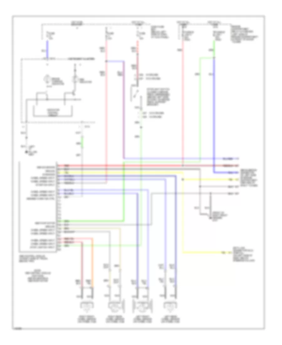
ANTI-LOCK BRAKES
Anti-lock Brake Wiring Diagrams for Hyundai Tiburon 1999
List of elements for Anti-lock Brake Wiring Diagrams for Hyundai Tiburon 1999:
- (front of right front fender) g101
- (left "c" pillar) g904
- (w/cruise)
- (w/o cruise)
- Abs bleeding connector (at left side of engine compartment, forward of strut tower)
- Abs control module (in right side of trunk, behind trim)
- Abs indicator
- Abs pump motor
- Abs solenoids
- Abs/ebd warn ind ctrl
- Brake warning indicator
- Dash fuse box (below left side of dash, at kick panel)
- Data link connector (dlc) (partial) (on left side of dash, below steering column)
- Diagnosis
- Engine compartment relay & fuse box (left side of engine compartment, in front of shock tower)
- Fuse 10a
- Fuse 15a
- Fusible link h 30a (pnk)
- Fusible link i 30a (pnk)
- Ground
- Hot at all times
- Hot in on or start
- I01-2
- Indicator control circuit
- Instrument cluster
- Left front wheel sensor (on wheel hub)
- Left rear wheel sensor (on wheel hub)
- M27
- M28
- Nca
- Note: abs control module contains: abs solenoids & abs pump motor
- Red
- Right front wheel sensor (on wheel hub)
- Right rear wheel sensor (on wheel hub)
- Start/on input
- Stop lamp sw input
- Stoplight switch (closed w/brake pedal depressed) (behind left side of dash, on brake pedal support bracket)
- Wheel speed input
 Čeština
 Dansk
Dansk Deutsch
 Ελληνικά
 English
 English
 Español
 Français
 Français
 עברית
עברית Hrvatski
 Magyar
 Italiano
 日本語
日本語 한국어
한국어 Nederlands
 Polski
 Português
 Português
 Română
 Русский
 Slovenčina
 Slovenščina
 Svenska
 Türkçe
 中文 (中国)
 Suomi
Suomi