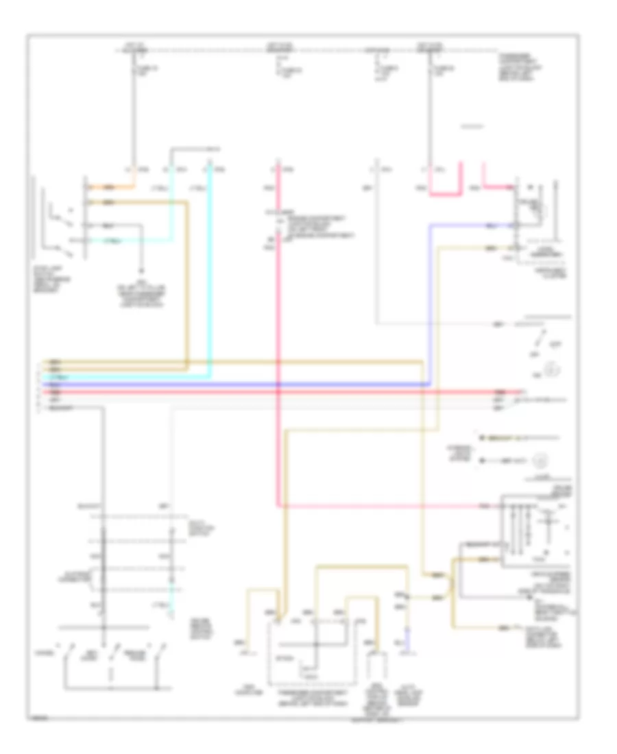
CRUISE CONTROL
Cruise Control Wiring Diagram (1 of 2) for Hyundai XG350 L 2005
 https://portal-diagnostov.com/license.html
Automotive Electricians Portal FZCO
Automotive Electricians Portal FZCO
https://portal-diagnostov.com/license.html
https://portal-diagnostov.com/license.html
Automotive Electricians Portal FZCO
Automotive Electricians Portal FZCO
List of elements for Cruise Control Wiring Diagram (1 of 2) for Hyundai XG350 L 2005:
- 87a
- Abs fuse 10a
- Accelerator position sensor (on throttle body)
- Aps sig (main)
- Aps sig (sub)
- Brake sig
- Burglar alarm relay
- C11
- C44-1
- C44-2
- C44-3
- Coast switch gnd
- Coast switch in
- Communication
- Ecm rly on
- Ecu fuse 10a
- Engine compartment junction block (on left front of engine compt)
- Etacm
- Ets control module (behind center of dash, on support bracket)
- Ets ind
- Ets motor (on right side of throttle body)
- Ets relay
- Ets rly cntl
- F10
- Fuse 32 10a
- Fuse 4 15a
- G11 (on firewall, near throttle housing)
- G13 (under center console, right of srs control module)
- G15 (under center console, at left rear of srs control module)
- Ground
- Hot at all times
- Hot in on or start
- Hot in start
- Hot with ecm ctrl relay energized
- I/p-h
- I/p-p
- Idle sw
- Idle switch
- Injector fuse 10a
- J/c c42 (lower left center of dash)
- Jc01
- Jm09
- Limp home valve (on right rear of engine, near throttle body)
- Limp home vlv
- M33-3
- Memory pwr
- Motor
- Motor pwr
- On/start
- Oxygen sensor fuse 15a
- P/n input
- Passenger compartment junction block (behind left end of dash)
- Passenger compartment relay box (behind left end of dash, on support bracket)
- Pcm (behind lower center of dash)
- Pnk
- Red
- Sensor pwr (5v)
- Source
- Start relay
- Start sig
- Stop lamp sw in
- Sw ind
- Throttle position sensor (on left side of throttle body)
- Tps sig (1)
- Tps sig (2)
- Transaxle range switch
- Vehicle speed in
Cruise Control Wiring Diagram (2 of 2) for Hyundai XG350 L 2005
List of elements for Cruise Control Wiring Diagram (2 of 2) for Hyundai XG350 L 2005:
- A11
- Auto head lamp leveling sensor
- Cancel
- Cruise ind
- Cruise remote control switch
- Cruise switch
- Data link connector (below left side of dash)
- Engine compartment junction block (on left front of engine compartment)
- Eps control module (behind center of dash, on support bracket)
- Etacm
- Fuse 19 15a
- Fuse 23 10a
- Fuse 28 10a
- Fuse 9 10a
- G03 (on left "a" pillar, near passenger compartment junction block)
- G11 (on firewall, near throttle housing)
- Hall ic
- Hot at all times
- Hot in on
- Hot in on or start
- I/p-b
- I/p-e
- I/p-h
- I/p-j
- I/p-k
- I18-2
- Illum
- Ind
- Instrument cluster
- Interior lights system
- Jc01
- Jm09
- M33-3
- Micro computer
- Multi- function switch
- Nca
- Off
- Passenger compartment junction block (behind left end of dash)
- Pnk
- Red
- Resume/ accel
- Set/ coast
- Slip ring connector
- Stop lamp switch (above brake pedal, on bracket)
- Trip computer
- Vehicle speed sensor (on top right side of transaxle)

 Čeština
 Dansk
Dansk Deutsch
 Ελληνικά
 English
 English
 Español
 Français
 Français
 עברית
עברית Hrvatski
 Magyar
 Italiano
 日本語
日本語 한국어
한국어 Nederlands
 Polski
 Português
 Português
 Română
 Русский
 Slovenčina
 Slovenščina
 Svenska
 Türkçe
 中文 (中国)