CRUISE CONTROL
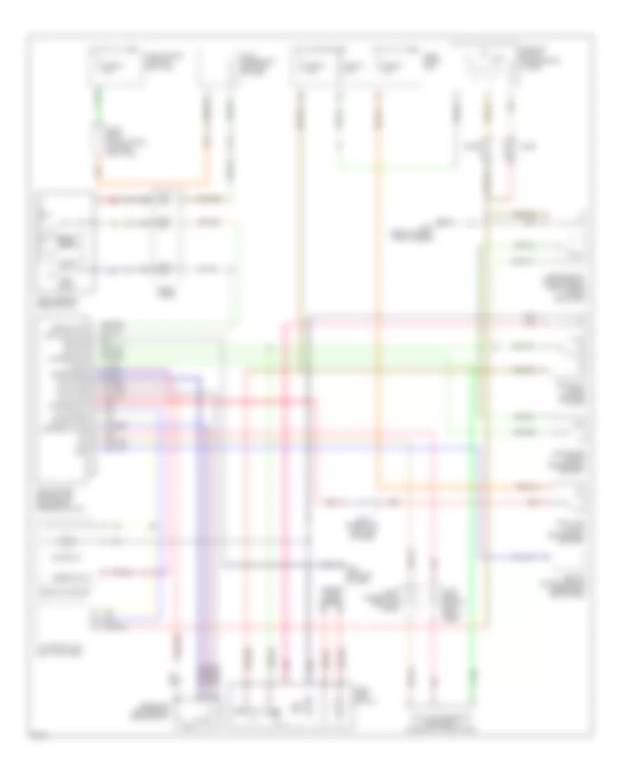
Cruise Control Wiring Diagram for Infiniti Q45 1997
List of elements for Cruise Control Wiring Diagram for Infiniti Q45 1997:
- 13h
- 17b
- A/t control unit (left kick panel)
- Abs/tcs control module (upper right end of dash)
- Air valve
- Ascd (cruise) control unit (left side of steering column)
- Ascd brake switch (brake pedal bracket)
- Ascd hold relay (left side of dash)
- Ascd main switch
- Ascd pump (left rear of engine compt)
- Ascd steering wheel switch
- Cancel
- Clock
- Combination meter
- Cruise ind
- Cruise lamp
- Data link connector for consult (under left side of dash)
- Diode
- Fuse 18 10a
- Fuse 32 7.5a
- Fuse 37 15a
- Fuse 64 15a
- Fuse block (j/b)
- Fuse, fusible link and relay box
- G101 (front of right front fender)
- G202 (left end of dash)
- Ground
- Horn relay (fuse, fusible link and relay box)
- Hot at all times
- Hot in on or start
- Inhibitor switch (transmission tunnel)
- Interior lights system
- Joint conn- ector 2 (left end of dash)
- Joint connector 1 (left end of dash)
- Joint connector 7 (left end of dash)
- Joint connector 8 (left kick panel)
- Main sw
- Nc brake sw
- Nca
- No brake sw
- O/d cancel
- Off
- On ind
- Park/neutral position relay (fuse, fusible link and relay box)
- Pnk
- Pump pwr
- Red
- Release valve
- Res/acc sw
- Resume/ accel
- Set/ coast
- Set/coast sw
- Speed sig out
- Spiral cable
- Spped sens
- Stop lamp switch (brake pedal bracket)
- Tcs
- Vac motor
 Čeština
 Dansk
Dansk Deutsch
 Ελληνικά
 English
 English
 Español
 Français
 Français
 עברית
עברית Hrvatski
 Magyar
 Italiano
 日本語
日本語 한국어
한국어 Nederlands
 Polski
 Português
 Português
 Română
 Русский
 Slovenčina
 Slovenščina
 Svenska
 Türkçe
 中文 (中国)
 Suomi
Suomi