SHIFT INTERLOCKS
Shift Interlock Wiring Diagram for Land Rover Defender 90 1997
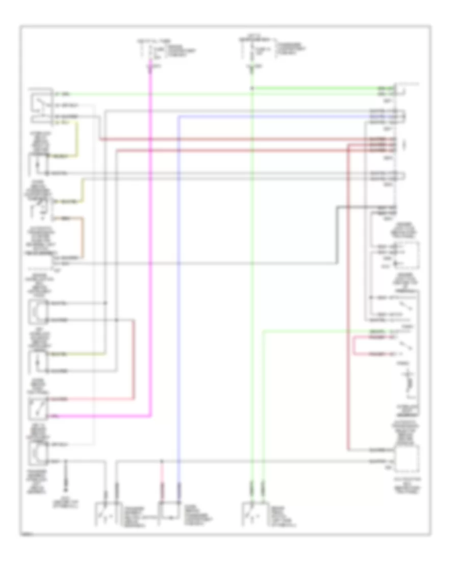
List of elements for Shift Interlock Wiring Diagram for Land Rover Defender 90 1997:
- Automatic transmission selector (behind center console)
- Automatic transmission starter inhibitor/ reverse light switch (above gearbox)
- Brake pedal switch (left side of firewall)
- C285
- C286
- C287
- C289
- C550
- C57
- C62
- Diode (behind dash trim panel)
- Diode (behind passenger compartment fuse box)
- Engine compartment fuse box
- Engine immobilization ecu (behind instrument pack)
- Fuse 18 15a
- Fuse 20a
- G121
- G121 (center top of firewall)
- Header joint k108 (center top of firewall)
- Header joint k109 (behind dash trim panel)
- Hot at all times
- Hot in start and run
- Interlock relay (behind front of center console)
- Interlock shift solenoid
- Key in sensor (behind instrument pack)
- Key interlock solenoid (behind instrument pack)
- Multifuction ecu (behind dash trim panel)
- Park1
- Park2
- Passenger compartment fuse box
- Transfer gearbox interlock unit (above gearbox)
- Transfer gearbox neutral switch (above gearabox)
 Čeština
 Dansk
Dansk Deutsch
 Ελληνικά
 English
 English
 Español
 Français
 Français
 עברית
עברית Hrvatski
 Magyar
 Italiano
 日本語
日本語 한국어
한국어 Nederlands
 Polski
 Português
 Português
 Română
 Русский
 Slovenčina
 Slovenščina
 Svenska
 Türkçe
 中文 (中国)
 Suomi
Suomi