AIR CONDITIONING
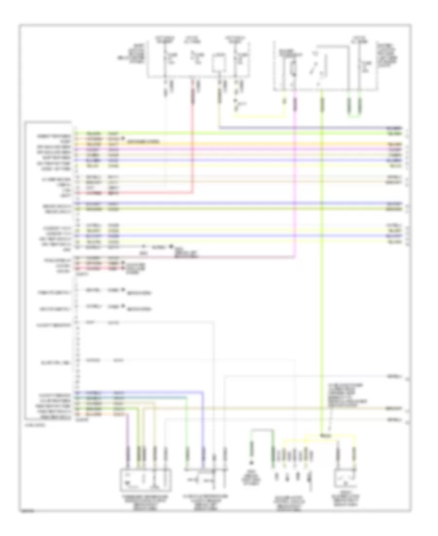
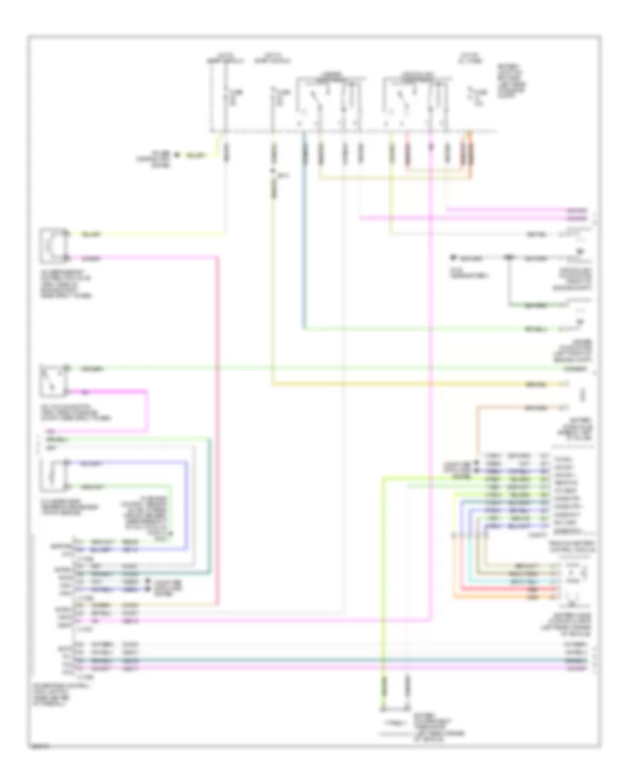
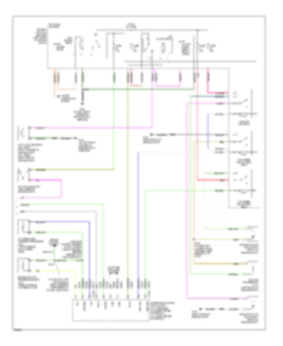
Automatic A/C Wiring Diagram, Except Hybrid (1 of 3) for Mercury Mariner 2008
 https://portal-diagnostov.com/license.html
Automotive Electricians Portal FZCO
Automotive Electricians Portal FZCO
https://portal-diagnostov.com/license.html
https://portal-diagnostov.com/license.html
Automotive Electricians Portal FZCO
Automotive Electricians Portal FZCO
List of elements for Automatic A/C Wiring Diagram, Except Hybrid (1 of 3) for Mercury Mariner 2008:
- (right side of dash) s225
- 5v vref return
- Ambient temp sens
- Battery junction box (bjb) (left front of engine compt)
- Blower motor control module (right side of dash)
- Blower motor relay
- Blwr ctrl (vbc)
- C2280a
- C2280b
- C2280e
- C2357a
- C2357b
- Cbp37
- Ch122
- Ch123
- Ch207
- Ch208
- Ch212
- Ch213
- Ch228
- Ch229
- Ch238
- Ch239
- Ch402
- Chs29
- Chs30
- Computer data lines system
- Defogger system
- Drv htd seat rly
- Drv sunload sens
- Drv temp act fdbk
- Drv temp dr ccw
- Drv temp dr cw
- Evap temp sens
- Fr blwr relay
- Front blower motor (right side of dash)
- Fuse 10a
- Fuse 40a
- Fuse 5a
- G200 (behind right side of dash)
- G202 (behind left side of dash)
- Gd112
- Gd114
- Gnd
- Hot at all times
- Hot in run or acc
- Hot in run or start
- Hvac (datc)
- In car temp sens
- In-vehicle temperature sensor (left side of dash)
- Lh111
- Logic
- Mode 1 act fdbk
- Mode dr 1 ccw
- Mode dr 1 cw
- Mot+
- Mot-
- Ms can+
- Ms can-
- Pass htd seat rly
- Pass temp act fdbk
- Pass temp dr ccw
- Pass temp dr cw
- Passenger temperature blend door actuator (right side of dash, on hvac assembly)
- Power distribution system
- Pwm
- R-def
- Recirc dr ccw
- Recirc dr cw
- Rh111
- S202
- Sbp15
- Seats system
- Smart junction box (sjb) (below center of dash)
- V batt
- V ign
- V ref 5v
- Vdb06
- Vdb07
- Vh101
- Vh301
- Vh406
- Vh407
- Vh414
- Vh416
- Vh417
- Vh436
- Vh440
- Vh441
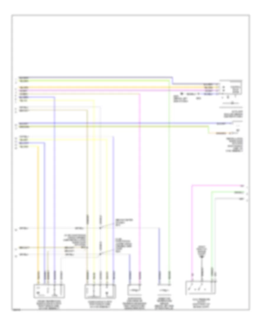
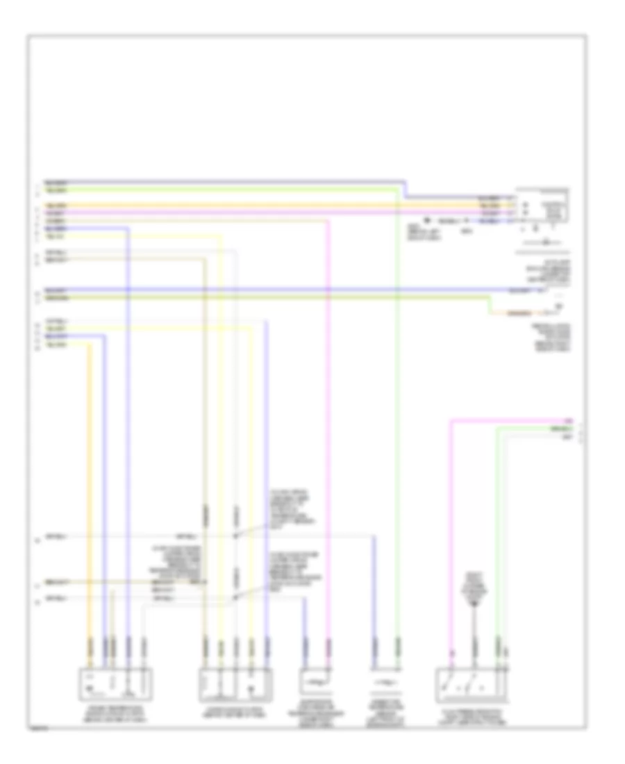
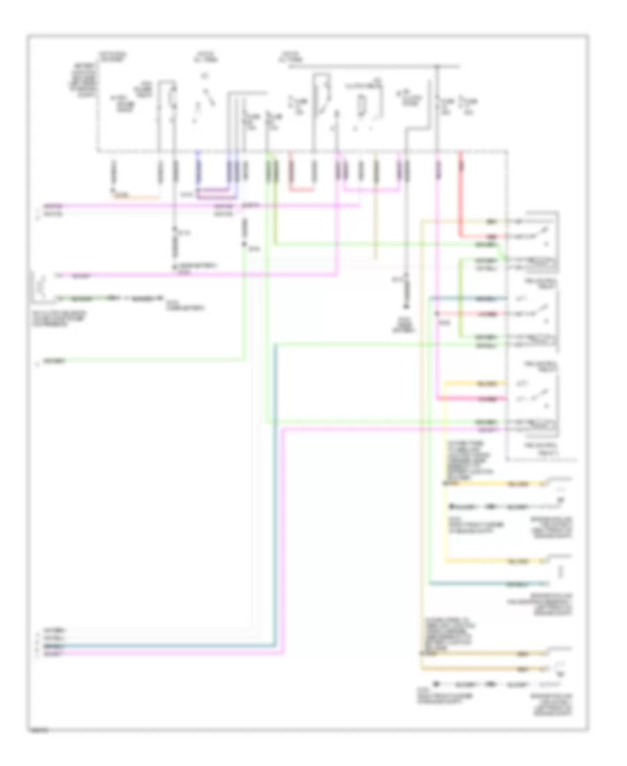
Automatic A/C Wiring Diagram, Except Hybrid (2 of 3) for Mercury Mariner 2008
List of elements for Automatic A/C Wiring Diagram, Except Hybrid (2 of 3) for Mercury Mariner 2008:
- (behind center of dash) s210
- (in air conditioning jumper wiring harness, near c2029) s222
- (in air conditioning wiring harness, near recirculation blend door actuator) s223
- (right front of engine compt) g103
- Ambient air temperature sensor (behind left side of front grille)
- Autolamp/ sunload sensor (center of dash)
- Control solid state
- Driver temperature blend door actuator (right side of dash, on hvac assembly)
- Dual pressure switch (right front of engine compt)
- Evaporator discharge air temperature sensor (right side of dash, near evaporator)
- G202 (behind left side of dash)
- Mode door actuator (right side of dash, on hvac assembly)
- Recirculation blend door actuator (right side of dash, on hvac assembly)
- S202
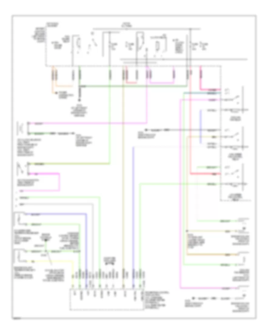
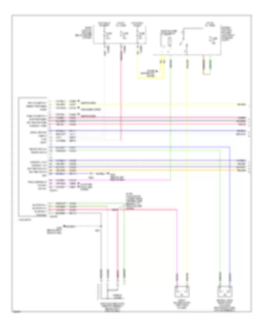
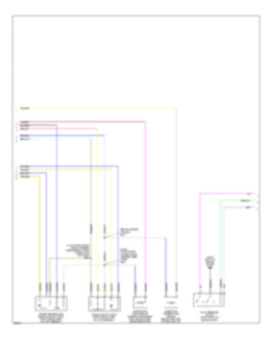
Automatic A/C Wiring Diagram, Except Hybrid (3 of 3) for Mercury Mariner 2008
List of elements for Automatic A/C Wiring Diagram, Except Hybrid (3 of 3) for Mercury Mariner 2008:
- (in engine control sensor & fuel charge wiring harness, before breakout to fuel injector 3)
- (in fuel shut off off solenoid wiring harness, near breakout to fuel injector 6)
- A/c clutch diode (early produ- ction)
- A/c clutch relay
- A/c clutch solenoid (2.3l: right front corner of engine compt) (3.0l: right front side of engine compt)
- A/c cycling switch (right rear of engine compt)
- Accr
- Accs
- Acpsw
- Battery junction box (bjb) (left front of engine compt)
- C175b
- C175e
- Can+
- Can-
- Cec01
- Cec02
- Ch302
- Ch421
- Ch425
- Cht
- Computer data lines system
- Cooling fan relay
- Cooling fan resistor (2.3l) (left front of engine compt)
- Cylinder head temperature sensor (2.3l) (top of engine, on cylinder head)
- Ect
- Engine controls system
- Engine coolant temperature (ect) (3.0l) (rear of engine in water outlet)
- Engine cooling fan motor 1 (front of engine compt)
- Engine cooling fan motor 2 (front of engine compt)
- Fan ctrl
- Fuse 10a
- Fuse 40a
- G102 (right front of engine compt)
- G104 (at left front corner of engine compt, near bjb)
- High speed fan control relay
- Hot at all times
- Hot in run or start
- Low speed fan control relay
- Pcm power diode
- Pcm power relay
- Power distribution system
- Powertrain control module (pcm) (3.0l: in recess on upper center of firewall) (2.3l: rear center of firewall)
- Re405
- Red
- S100
- S102
- S108 (in headlamp jumper wiring harness, near breakout to c139)
- S109
- S118
- S129
- Sigrtne
- Vdb04
- Vdb05
- Ve712
- Ve716
Automatic A/C Wiring Diagram, Hybrid (1 of 4) for Mercury Mariner 2008
List of elements for Automatic A/C Wiring Diagram, Hybrid (1 of 4) for Mercury Mariner 2008:
- (in air conditioner jumper wiring harness, near breakout to recirculation blend door actuator)
- 5v vref return
- Ambient temp sens
- Battery junction box (bjb) (left rear of engine compt)
- Blower motor control module (behind right side of dash)
- Blower motor relay
- Blwr ctrl (vbc)
- C2280a
- C2280b
- C2280e
- C2357a
- C2357b
- Cbp37
- Ch122
- Ch123
- Ch207
- Ch208
- Ch212
- Ch213
- Ch228
- Ch229
- Ch238
- Ch239
- Ch402
- Chs29
- Chs30
- Computer data lines system
- Defogger system
- Drv htd seat rly
- Drv sunload sens
- Drv temp act fdbk
- Drv temp dr ccw
- Drv temp dr cw
- Evap temp sens
- Fr blwr relay
- Front blower motor (behind right side of dash)
- Fuse 10a
- Fuse 40a
- Fuse 5a
- G200 (behind right end of dash)
- G202 (behind left end of dash)
- Gd112
- Gd114
- Gnd
- Hot at all times
- Hot in run or acc
- Hot in run or start
- Humidity sens pwr
- Humidity sens sig
- Hvac (datc)
- In car temp sens
- In-vehicle temperature/ humidity sensor (behind left side of dash)
- Lh111
- Lh115
- Logic
- Mode 1 act fdbk
- Mode dr 1 ccw
- Mode dr 1 cw
- Mot+
- Mot-
- Ms can+
- Ms can-
- Pass htd seat rly
- Pass temp act fdbk
- Pass temp dr ccw
- Pass temp dr cw
- Passenger temperature blend door actuator (behind right side of dash)
- Pwm
- R-def
- Recirc dr ccw
- Recirc dr cw
- Rh111
- S117
- S202
- S225
- Sbp15
- Seats system
- Smart junction box (sjb) (below center of dash)
- V batt
- V ign
- V ref 5v
- Vdb06
- Vdb07
- Vh101
- Vh301
- Vh406
- Vh407
- Vh413
- Vh414
- Vh416
- Vh417
- Vh436
- Vh440
- Vh441
Automatic A/C Wiring Diagram, Hybrid (2 of 4) for Mercury Mariner 2008
List of elements for Automatic A/C Wiring Diagram, Hybrid (2 of 4) for Mercury Mariner 2008:
- (in air conditioner jumper wiring harness, near breakout to temperature blend door actuator) s222
- (in air conditioner jumper wiring harness, near breakout to temperature blend door actuator) s223
- (in main wiring harness, near breakout to in-vehicle temperature/ humidity sensor) s210
- (right front corner of engine compt) g103
- Ambient air temperature sensor (left front of engine compt)
- Autolamp/ sunload sensor (under top center of dash)
- Control solid state
- Driver temperature blend door actuator (behind center of dash)
- Dual pressure switch (right side of engine compt, near strut tower)
- Evaporator discharge air temperature sensor (under right side of dash)
- G202 (behind left end of dash)
- Mode door actuator (behind center of dash)
- Recirculation blend door actuator (behind right side of dash)
- S202
Automatic A/C Wiring Diagram, Hybrid (3 of 4) for Mercury Mariner 2008
List of elements for Automatic A/C Wiring Diagram, Hybrid (3 of 4) for Mercury Mariner 2008:
- (in engine control sensor & fuel charge wiring harness, near breakout to coil on plug (cop) 4) s104
- (left rear corner of vehicle)
- A/c cycling switch (right side of engine compt, near strut tower)
- A/c refrigerant distribution valve (right side of engine compt, near strut tower)
- Accr
- Accs
- Acpsw
- Acrdv
- Battery compartment thermistor (left rear corner of vehicle)
- Battery junction box (bjb) (left rear of engine compt)
- Battery mode door actuator
- Battery zone valve (base of left "d" pillar)
- C175b
- C175e
- C175t
- C4227a
- Can+
- Can-
- Ce318
- Cec01
- Cec02
- Cec11
- Ch302
- Ch303
- Ch307
- Ch421
- Ch425
- Cht
- Computer data lines system
- Cyb10
- Cyb12
- Cyb13
- Cyb14
- Cylinder-head temperature sensor (top of engine)
- Fc1
- Fc2
- Fc3
- Fuse 10a
- Fuse 5a
- G105 (near battery)
- Heater pump motor (left front of engine compt)
- Heater pump relay
- Hot at all times
- Hot in start or run
- Hpcr
- Hs can +
- Hs can -
- M/e coolant pump motor (front of engine compt)
- M/e coolant pump relay
- Mecp
- Mode mtr +
- Mode mtr -
- Mode pot +
- Mode pot -
- Pot wpr
- Power distribution system
- Powertrain control module (pcm) (rear center of firewall)
- Re405
- Red
- Ryb07
- Ryb10
- S124
- S412
- Sigrtne
- Temp rtn
- Traction battery control module
- Txv sol
- Txv temp
- Vdb04
- Vdb05
- Ve712
- Vyb07
- Vyb11
Automatic A/C Wiring Diagram, Hybrid (4 of 4) for Mercury Mariner 2008
List of elements for Automatic A/C Wiring Diagram, Hybrid (4 of 4) for Mercury Mariner 2008:
- (in dash panel to headlamp junction wiring harness, near breakout to battery junction box (bjb) s122
- (in dash panel to headlamp junction wiring harness, near breakout to battery junction box (bjb)) s120
- (near battery) g104
- A/c clutch diode
- A/c clutch relay
- A/c clutch solenoid (on air conditioner compressor)
- Battery junction box (bjb) (left rear of engine compt)
- Engine cooling fan dropping resistor 1 (left front of engine compt)
- Engine cooling fan motor 1 (left front of engine compt)
- Engine cooling fan motor 2 (right front of engine compt)
- Fan control
- Fan control relay 1
- Fan control relay 2
- Fuse 10a
- Fuse 15a
- Fuse 40a
- G102 (right front corner of engine compt)
- G104 (near battery)
- Hot at all times
- Hot in run or start
- Pcm power diode
- Pcm power relay
- Red
- Relay 3
- S114
- S115
- S118
- S125
- S126
- S134
- S140
Manual A/C Wiring Diagram, Except Hybrid (1 of 3) for Mercury Mariner 2008
List of elements for Manual A/C Wiring Diagram, Except Hybrid (1 of 3) for Mercury Mariner 2008:
- (in air conditioning jumper wiring harness, near breakout to front blower motor)
- Ambient temp sens
- Battery junction box (bjb) (left front of engine compt)
- Blwr sw h
- Blwr sw m-h
- Blwr sw m-l
- C2280a
- C2280b
- C2280e
- C2357a
- C2357b
- Cbp37
- Ch122
- Ch123
- Ch207
- Ch208
- Ch228
- Ch229
- Ch238
- Ch239
- Ch428
- Ch429
- Ch430
- Chs29
- Chs30
- Computer data lines system
- Defogger system
- Drv htd seat rly
- Drv temp dr ccw
- Drv temp dr cw
- Drv temp dr fdbk
- Evap temp sens
- Fr blower relay
- Front blower motor (right side of dash)
- Front blower motor relay
- Front blower motor resistor assembly (behind right side of dash)
- Fuse 10a
- Fuse 40a
- Fuse 5a
- G200 (behind right side of dash)
- G202 (behind left side of dash)
- Gd112
- Gd114
- Gnd
- Hot at all times
- Hot in run or acc
- Hot in run or start
- Hvac (emtc)
- Lh111
- Mode dr 1 ccw
- Mode dr 1 cw
- Mode dr 1 fdbk
- Ms can+
- Ms can-
- Pass htd seat rly
- Power distribution system
- Pwr gnd
- R-def
- Recirc dr ccw
- Recirc dr cw
- Recirculation blend door actuator (right side of dash, on hvac assembly)
- Rh111
- S201
- S202
- S224
- Sbp15
- Seats system
- Signal return
- Smart junction box (sjb) (below center of dash)
- Thermal limiter
- V batt
- V ign
- V ref 5v
- Vdb06
- Vdb07
- Vh406
- Vh407
- Vh436
- Vh440
Manual A/C Wiring Diagram, Except Hybrid (2 of 3) for Mercury Mariner 2008
List of elements for Manual A/C Wiring Diagram, Except Hybrid (2 of 3) for Mercury Mariner 2008:
- (behind center of dash) s210
- (in air conditioning jumper wiring harness, near c2029) s222
- (in air conditioning wiring harness, near recirculation blend door actuator) s223
- (right front of engine compt) g103
- Ambient air temperature sensor (behind left side of front grille)
- Driver temperature blend door actuator (right side of dash, on hvac assembly)
- Dual pressure switch (right front of engine compt)
- Evaporator discharge air temperature sensor (right side of dash, near evaporator)
- Mode door actuator (right side of dash, on hvac assembly)
Manual A/C Wiring Diagram, Except Hybrid (3 of 3) for Mercury Mariner 2008
List of elements for Manual A/C Wiring Diagram, Except Hybrid (3 of 3) for Mercury Mariner 2008:
- (in engine control sensor & fuel charge wiring harness, before breakout to fuel injector 3)
- (in fuel shut off off solenoid wiring harness, near breakout to fuel injector 6)
- A/c clutch diode (early produ- ction)
- A/c clutch relay
- A/c clutch solenoid (2.3l: right front corner of engine compt) (3.0l: right front side of engine compt)
- A/c cycling switch (right rear of engine compt)
- Accr
- Accs
- Acpsw
- Battery junction box (bjb) (left front of engine compt)
- C175b
- C175e
- Can+
- Can-
- Cec01
- Cec02
- Ch302
- Ch421
- Ch425
- Cht
- Computer data lines system
- Cooling fan relay
- Cooling fan resistor (2.3l) (left front of engine compt)
- Cylinder head temperature sensor (2.3l) (top of engine, on cylinder head)
- Ect
- Engine control system
- Engine coolant temperature (ect) (3.0l) (rear of engine in water outlet)
- Engine cooling fan motor 1 (front of engine compt)
- Engine cooling fan motor 2 (front of engine compt)
- Fan ctrl
- Fuse 10a
- Fuse 40a
- G102 (right front of engine compt)
- G104 (at left front corner of engine compt, near bjb)
- High speed fan control relay
- Hot at all times
- Hot in run or start
- Low speed fan control relay
- Pcm power diode
- Pcm power relay
- Power distribution system
- Powertrain control module (pcm) (3.0l: in recess on upper center of firewall) (2.3l: rear center of firewall)
- Re405
- Red
- S100
- S102
- S108 (in headlamp jumper wiring harness, near breakout to c139)
- S109
- S118
- S129
- Sigrtne
- Vdb04
- Vdb05
- Ve712
- Ve716

 Čeština
 Dansk
Dansk Deutsch
 Ελληνικά
 English
 English
 Español
 Français
 Français
 עברית
עברית Hrvatski
 Magyar
 Italiano
 日本語
日本語 한국어
한국어 Nederlands
 Polski
 Português
 Português
 Română
 Русский
 Slovenčina
 Slovenščina
 Svenska
 Türkçe
 中文 (中国)