AIR CONDITIONING
A/C Wiring Diagram for Oldsmobile Cutlass GL 1998
 https://portal-diagnostov.com/license.html
Automotive Electricians Portal FZCO
Automotive Electricians Portal FZCO
https://portal-diagnostov.com/license.html
https://portal-diagnostov.com/license.html
Automotive Electricians Portal FZCO
Automotive Electricians Portal FZCO
List of elements for A/C Wiring Diagram for Oldsmobile Cutlass GL 1998:
- 2.4l l4
- 3.1l v6
- 5 volts
- A/c bfc fuse 10a
- A/c compressor clutch
- A/c compressor clutch diode
- A/c compressor clutch relay
- A/c disable
- A/c on ind
- A/c refigerant pressure sensor (on front of engine compt)
- A/c req input
- A/c request
- A/c request logic
- A/c switch
- A10
- A11
- Air temp logic
- Air temperature actuator (top right side of dash)
- B11
- Bat
- Battery
- Blower motor
- Blower motor relay
- Blower resistor assembly (below right side of dash)
- Blower switch
- Body function controller (below right side of dash)
- C10
- Clutch rly ctrl
- Cool fan 1 fuse 30a
- Cool fan 2 fuse 15a
- D10
- D11
- Defog on ind
- Defog rel ctrl
- Defog request logic
- Defog switch
- Defogger system
- F11
- Fan control relay 1
- Fan control relay 2
- G112 (3.1l v6) (left side of engine)
- G125 (2.4l l4) (front of engine)
- G201 (right side of dash)
- G202 (left side of dash)
- Ground
- Heater a/c control assembly
- Hi blo mot fuse 30a
- Hot at all times
- Hot in run
- Hot in run or start
- Htr a/c ign fuse 10a
- Htr out
- Hvac blower fuse 20a
- Ign
- Ignition
- Illum
- Interior lights system
- Ipc/hvac batt fuse 10a
- Left cooling fan motor
- Left fan ctrl
- Left i/p junction block
- Mode control relay
- Off
- Powertrain control module (below left side ofdash, next to steering column)
- Red
- Right cooling fan motor
- Right fan ctrl
- Right i/p junction block
- Sensor ground
- Sensor signal
- Ser data cls 2
- Step dim input
- Tan
- Temp req
- Underhood junction block
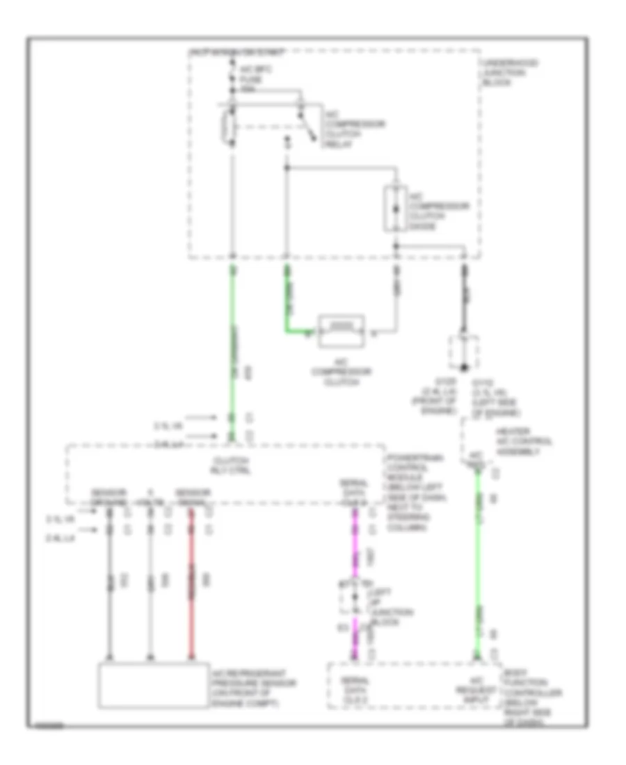
Compressor Wiring Diagram for Oldsmobile Cutlass GL 1998
List of elements for Compressor Wiring Diagram for Oldsmobile Cutlass GL 1998:
- 2.4l l4
- 3.1l v6
- A/c bfc fuse 10a
- A/c compressor clutch
- A/c compressor clutch diode
- A/c compressor clutch relay
- A/c refrigerant pressure sensor (on front of engine compt)
- A/c req
- A/c request input
- Body function controller (below right side of dash)
- Clutch rly ctrl
- G112 (3.1l v6) (left side of engine)
- G125 (2.4l l4) (front of engine)
- Heater a/c control assembly
- Hot in run or start
- Left i/p junction block
- Powertrain control module (below left side of dash, next to steering column)
- Sensor ground
- Sensor signal
- Serial data cls 2
- Underhood junction block
- Volts

 Čeština
 Dansk
Dansk Deutsch
 Ελληνικά
 English
 English
 Español
 Français
 Français
 עברית
עברית Hrvatski
 Magyar
 Italiano
 日本語
日本語 한국어
한국어 Nederlands
 Polski
 Português
 Português
 Română
 Русский
 Slovenčina
 Slovenščina
 Svenska
 Türkçe
 中文 (中国)