ANTI-LOCK BRAKES
Anti-lock Brakes Wiring Diagram for Ford Excursion 2005
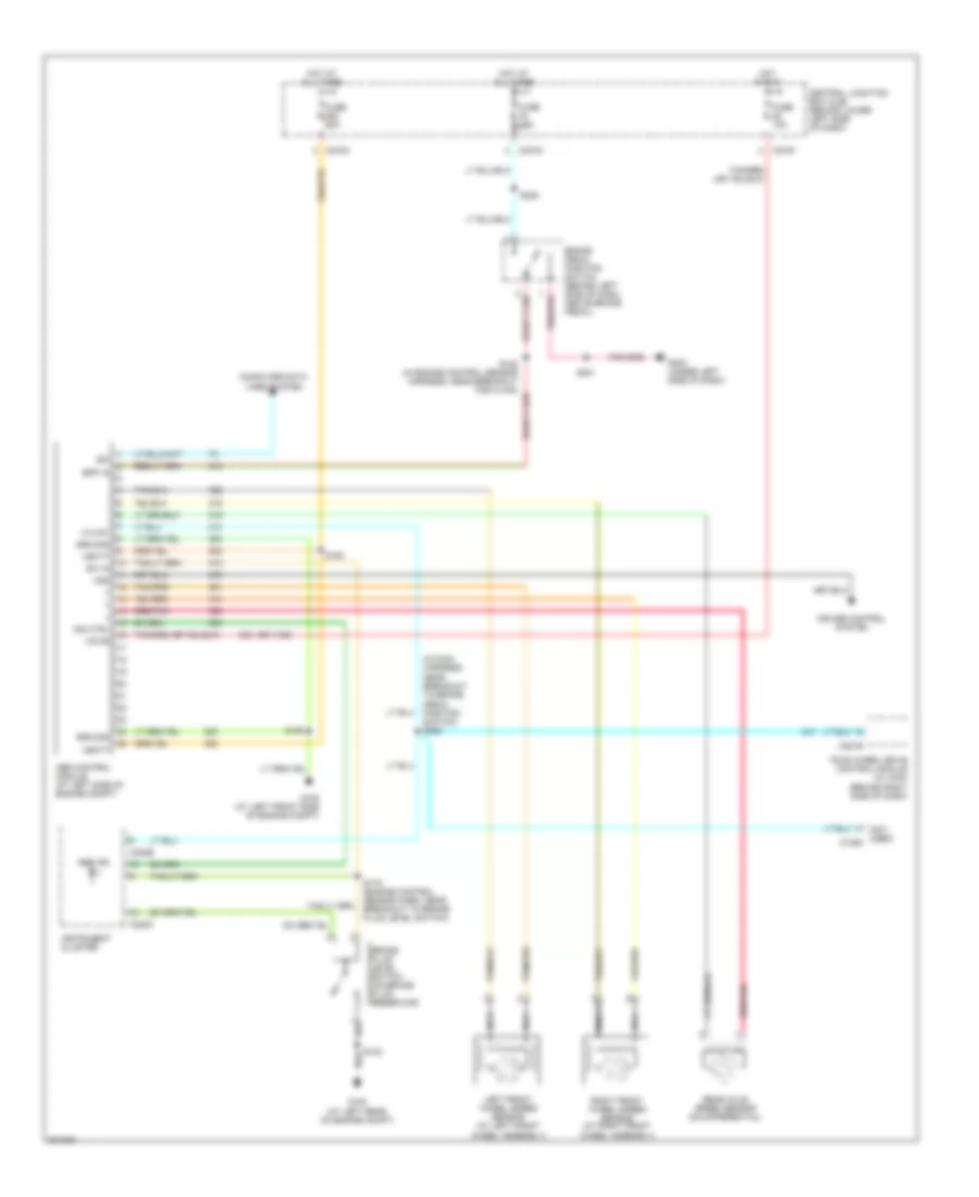
List of elements for Anti-lock Brakes Wiring Diagram for Ford Excursion 2005:
- (behind right side of dash)
- (in main harness, near breakout to brake pedal position switch) s259
- (not used) c1393
- (or 1155)
- Abs control module (at left side of engine compt)
- Abs ind
- Bpp in
- Brake fluid level switch (on brake fluid reservoir)
- Brake pedal position switch (behind left side of dash, above brake pedal)
- C220b
- C220c
- C270a
- C270f
- C270m
- C281b
- Central junction box (cjb) (behind lower left side of dash)
- Computer data lines system
- Cruise control system
- Four wheel drive control module (w/ 4wd)
- Fuse 10a
- Fuse 60a
- G100 (at left rear of engine compt)
- G105 (at left front side of engine compt)
- G300 (under left side of dash)
- Ground
- Hi/low
- Hot at all times
- Hot in run
- Ind ctrl
- Instrument cluster
- Iso
- Left front wheel speed sensor (at left front wheel assembly)
- Nca
- Rear axle speed sensor (on differential)
- Red/pnk
- Right front wheel speed sensor (at right front wheel assembly)
- S102
- S159
- S163
- S178 (engine control sensor harn, near breakout to brake fluid level switch)
- S201
- S228
- Sw in
- Vbatt
- Vpwr
- Vss
 Čeština
 Dansk
Dansk Deutsch
 Ελληνικά
 English
 English
 Español
 Français
 Français
 עברית
עברית Hrvatski
 Magyar
 Italiano
 日本語
日本語 한국어
한국어 Nederlands
 Polski
 Português
 Português
 Română
 Русский
 Slovenčina
 Slovenščina
 Svenska
 Türkçe
 中文 (中国)
 Suomi
Suomi