ANTI-LOCK BRAKES
Anti-lock Brakes Wiring Diagram for Mercury Grand Marquis GS 2004
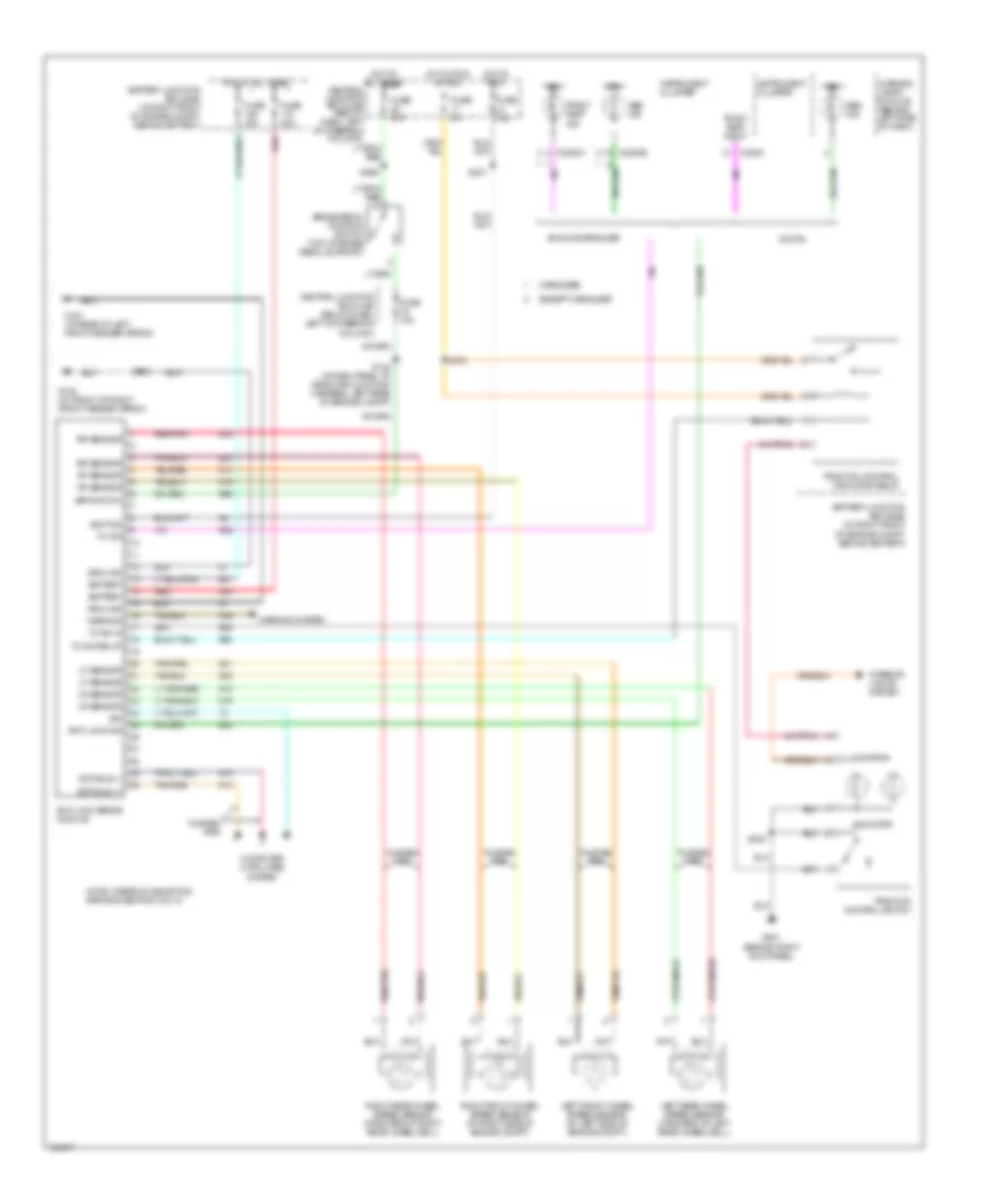
List of elements for Anti-lock Brakes Wiring Diagram for Mercury Grand Marquis GS 2004:
- Abs ind
- Analog/marauder
- Anti-lock brake module
- Anti-lock ind
- Battery
- Battery junction box (bjb) (in right front of engine compt, behind battery)
- Bpp switch
- Brake pedal position switch (top of brake pedal support)
- C220c
- C2220a
- C2220b
- Central junction box (cjb) (below dash, left of steering column)
- Computer data lines system
- Digital
- Except marauder
- Fuse 10a
- Fuse 15a
- Fuse 20a
- Fuse 40a
- Fuse 5a
- G101 (at rear of left front fender apron)
- G102 (at front of right front fender apron)
- G201 (behind right kick panel)
- Ground
- Hot at all times
- Hot in run
- Hot in run or acc
- Ign
- Ignition
- Illumination
- Indicator
- Instrument cluster
- Interior lights system
- Iso
- Left front wheel speed sensor (at left side of engine compt)
- Left rear wheel speed sensor (forward of left rear wheelwell)
- Lf sensor
- Lr sensor
- Marauder
- Note: there is a shorting bar across pins 15 & 16
- Red
- Red/pnk
- Rf sensor
- Right front wheel speed sensor (at right side of engine compt)
- Right rear wheel speed sensor (forward of right rear wheelwell)
- Rr sensor
- S112
- S132 (in dash panel to headlamp junction harness, left rear of engine compt)
- S154
- S224
- S231
- S265
- Scp bus (+)
- Scp bus (-)
- Tc ind
- Tc ind relay
- Tc sw in
- Tract asst ind
- Tract asst input
- Traction control indicator relay
- Traction control switch
- Twisted pair
- Warning
- Warning lamps module (behind left side of dash)
- Warning system
 Čeština
 Dansk
Dansk Deutsch
 Ελληνικά
 English
 English
 Español
 Français
 Français
 עברית
עברית Hrvatski
 Magyar
 Italiano
 日本語
日本語 한국어
한국어 Nederlands
 Polski
 Português
 Português
 Română
 Русский
 Slovenčina
 Slovenščina
 Svenska
 Türkçe
 中文 (中国)
 Suomi
Suomi