ENGINE PERFORMANCE
2.0L
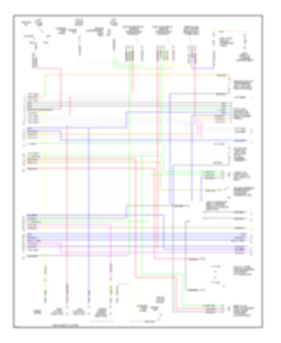
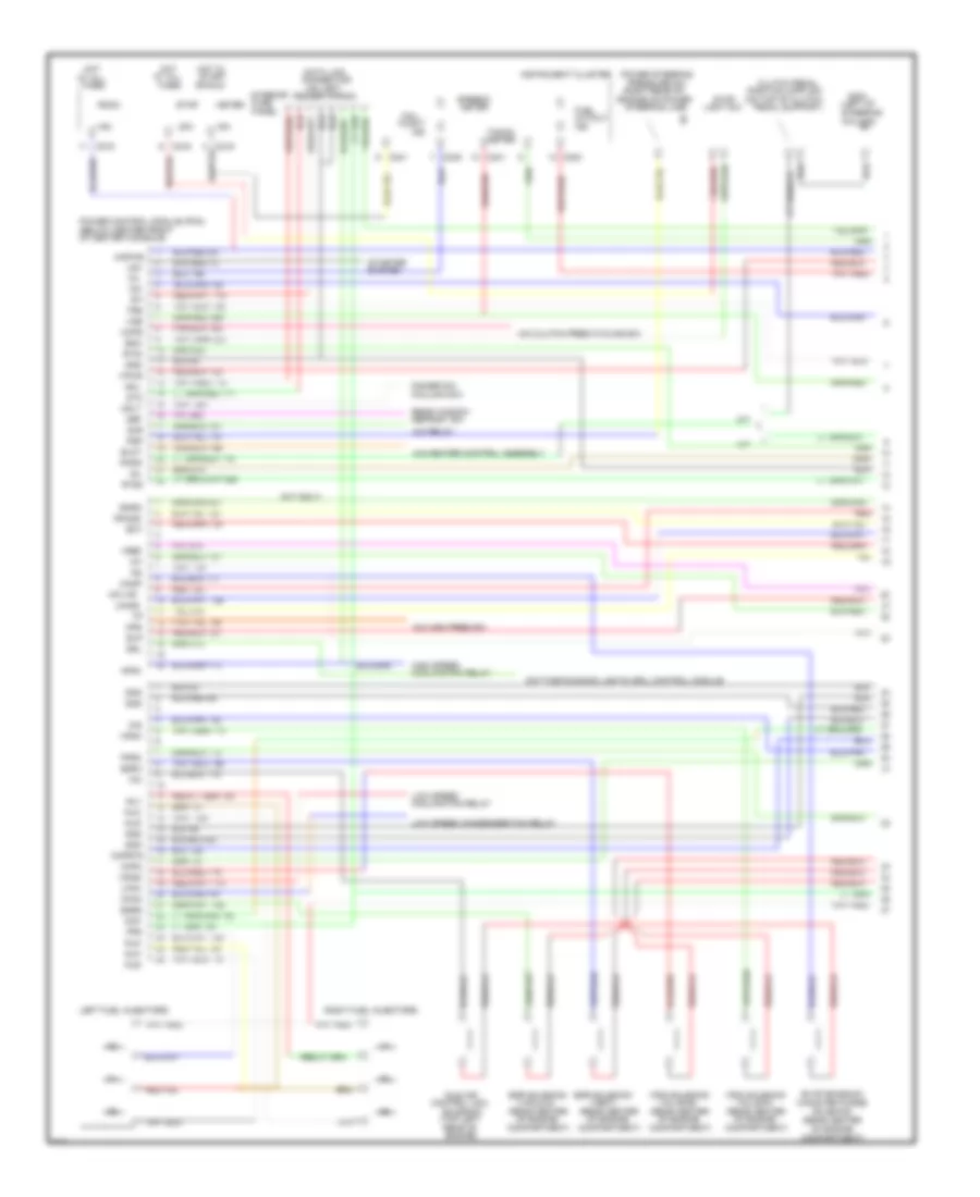
2.0L, Engine Performance Wiring Diagrams, A/T (1 of 3) for Ford Probe GT 1995
 https://portal-diagnostov.com/license.html
Automotive Electricians Portal FZCO
Automotive Electricians Portal FZCO
https://portal-diagnostov.com/license.html
https://portal-diagnostov.com/license.html
Automotive Electricians Portal FZCO
Automotive Electricians Portal FZCO
List of elements for 2.0L, Engine Performance Wiring Diagrams, A/T (1 of 3) for Ford Probe GT 1995:
- (below center
- (brake
- (canp) solenoid
- (center of
- (left front
- (left side
- (lower front
- (lower left side
- (lower rear
- (maf) sensor
- (near ignition
- (near left
- (on rear of
- (right rear
- (vacuum)
- (vent)
- 15a
- 20a
- A/c
- A/c control assembly
- A/c relay
- Acd
- Acon
- Air cleaner
- Assembly)
- At all
- Blr
- Boo
- Brake
- Canister purge
- Canp
- Capacitor
- Center console)
- Center of engine
- Cid
- Clutch cycling
- Coil)
- Compartment)
- Connector
- Control
- Control (iac)
- Crankshaft
- Data (+)
- Data (-)
- Daytime
- Def
- Dimmer sw (column sw)
- Distributor
- Drl
- Ect
- Egr solenoid
- Egra
- Egrp
- Egrv
- Engine
- Epc
- Evap emission
- Fender apron)
- Fog lt)
- Fpm
- Fprc
- Fprc solenoid
- Front of
- Fuel
- Fuse
- G104
- G105 (left side of engine,
- G106 joint
- G110 joint
- Hdl
- Heated oxygen
- Hfc
- High speed cooling fan relay
- Ho2s
- Ho2s gnd
- Hot
- Iac bpa
- Iat
- Idle air
- Idm
- Ign gnd
- Ignition coil
- Ignition control
- In acc
- In exhaust
- Inj 1
- Inj 2
- Inj 3
- Inj 4
- Injectors
- Input (sti)
- Interior
- Kapwr
- Lfc
- Lights
- Low speed cooling fan relay
- Maf
- Maf rtn
- Manifold)
- Mass airflow
- Mlp
- Module (icm) (left
- Module (pcm)
- Nca
- Of engine
- Of engine compt)
- Of engine)
- Of transaxle)
- On engine mount)
- On/off
- Or run
- Panel
- Pedal
- Pip
- Position (ckp)
- Powertrain
- Pressure sw
- Psp
- Pwr gnd
- Radio noise
- Rear defrost sw
- Rear of engine
- Red
- Red 722
- Room
- Running
- Self test
- Sensor
- Sensor (ho2s)
- Sensor (vss)
- Sig rtn
- Solenoid
- Spout
- Spout test
- Ss1
- Ss2
- Ss3
- Sti
- Sto and mil
- Stop
- Support)
- Switch
- Tcc
- Tcil
- Tcs
- Tft
- Times
- Tss
- Vehicle speed
- Vpwr
- Vref
- Vss (+)
- Vss (-)
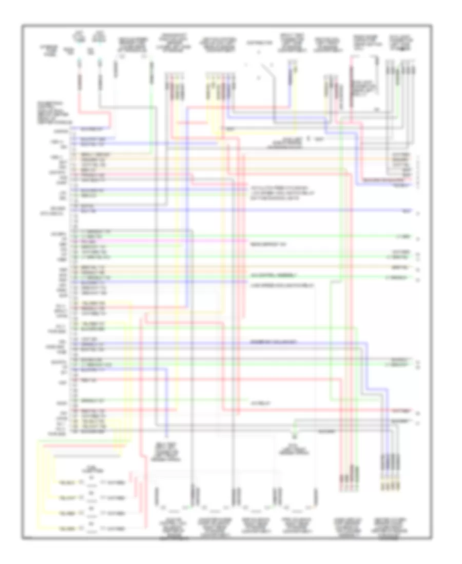
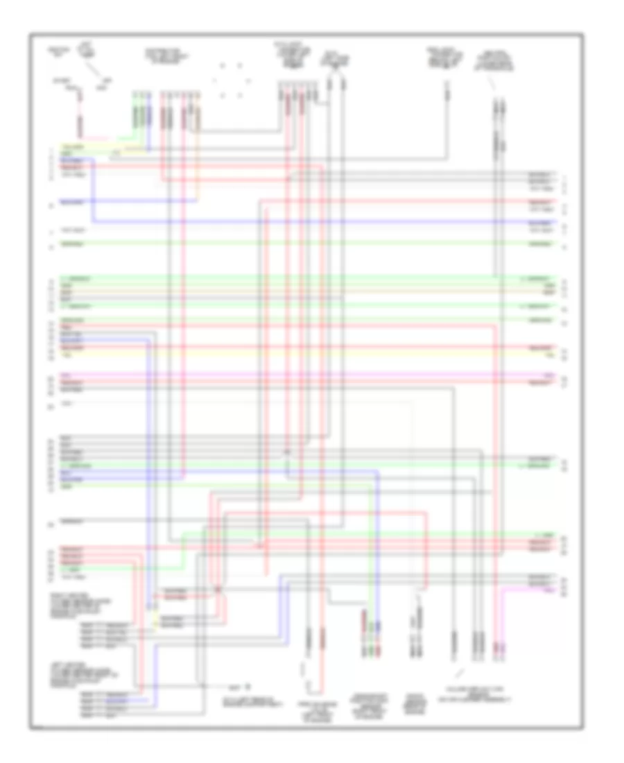
2.0L, Engine Performance Wiring Diagrams, A/T (2 of 3) for Ford Probe GT 1995
List of elements for 2.0L, Engine Performance Wiring Diagrams, A/T (2 of 3) for Ford Probe GT 1995:
- (behind right
- (below center
- (dlc) (on left
- (ect) (top left
- (engine
- (inside fuel
- (left side
- (on power
- (on throttle
- (rear of
- (right rear
- (top front
- 15a
- 30a
- Acc
- Apron)
- Assembly)
- At all
- B13
- Body)
- Box
- Cleaner
- Compartment
- Compartment)
- Connector
- Control
- Cutout
- Data link
- Egr valve
- Engine
- Engine coolant
- F/p
- Front fender
- Front of console,
- Fuel
- Fuel pump
- Fuel pump relay
- Function
- Fuse
- Fuse box)
- G407
- Hot
- Hot in
- Ig1
- Ignition
- Indicator
- Inertia fuel
- Inj
- Instrument cluster
- Intake air
- Interior
- Joint connector
- Luggage
- Mal/
- Manual lever
- Meter
- Mission
- Module
- Near pcm)
- Of air
- Of engine
- Of transaxle)
- Off
- Or run
- Panel
- Pcm power relay
- Position sensor
- Position sw
- Power steering
- Pressure sw
- Run
- Shutoff sw
- Side of engine)
- Start
- Steering line)
- Tacho
- Tank)
- Temp (iat)
- Temp sensor
- Throttle
- Times
- Trans/
- Wheelwell)
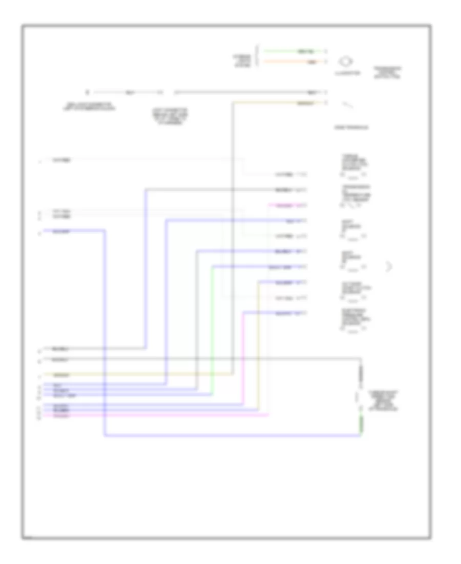
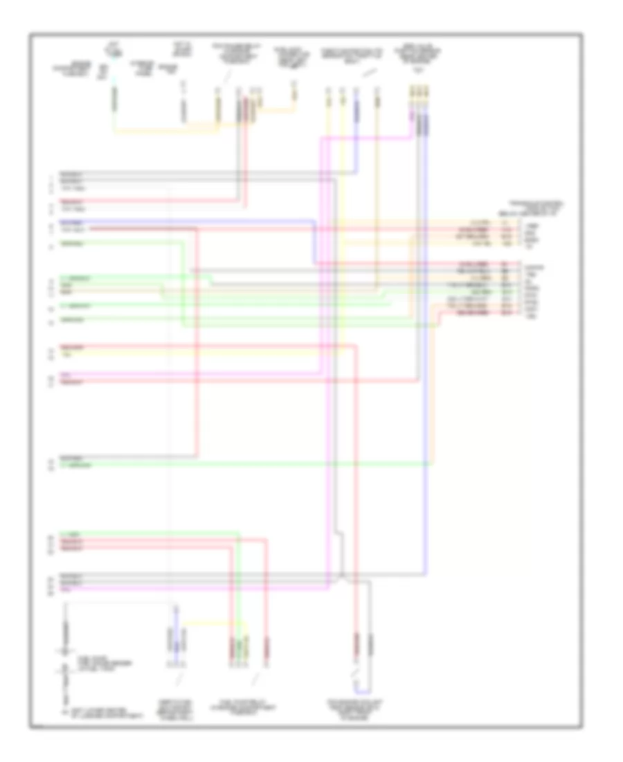
2.0L, Engine Performance Wiring Diagrams, A/T (3 of 3) for Ford Probe GT 1995
List of elements for 2.0L, Engine Performance Wiring Diagrams, A/T (3 of 3) for Ford Probe GT 1995:
- (behind left side
- (left of steering column)
- (left side
- (tot) sensor
- 3/2 timing/
- Cd4e transaxle
- Clutch (tcc)
- Coast clutch
- Control
- Control (epc)
- Converter
- Electronic
- G204 joint connector
- I/p harness)
- Illumination
- Interior
- Joint connector
- Lights
- Of i/p, taped to
- Of transaxle)
- Oil
- Pressure
- Sensor
- Shift
- Solenoid
- Speed (tss)
- Switch (tcs)
- System
- Temperature
- Transmission
- Turbine shaft
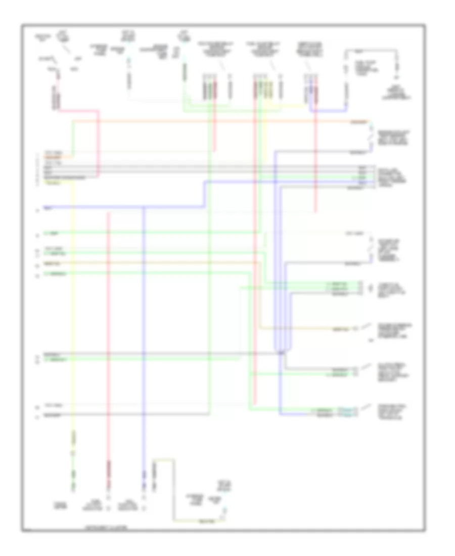
2.0L, Engine Performance Wiring Diagrams, M/T (1 of 2) for Ford Probe GT 1995
List of elements for 2.0L, Engine Performance Wiring Diagrams, M/T (1 of 2) for Ford Probe GT 1995:
- (below center
- (canp) solenoid
- (center of
- (left front
- (left side
- (lower front
- (lower left side
- (lower rear
- (maf) sensor
- (near ignition
- (near left
- (on rear of
- (right rear
- 15a
- A/c
- A/c clutch pres cycling sw
- A/c control assembly
- A/c relay
- Acd
- Acon
- Air cleaner
- Assembly)
- At all
- Blr
- Canister purge
- Canp
- Capacitor
- Center console)
- Center of engine
- Cid
- Coil)
- Compartment)
- Connector
- Control
- Control (iac)
- Crankshaft
- Daytime running lights
- Def
- Dimmer sw (column sw)
- Distributor
- Drl
- Ect
- Egr solenoid
- Engine
- Evr
- Fender apron)
- Fog lt)
- Fpm
- Fprc
- Fprc solenoid
- Front of
- Fuel
- Fuse
- G104
- G105 (left
- G106 joint
- G110 joint
- Hdl
- Heated oxygen
- Hfc
- High speed cooling fan relay
- Ho2s
- Ho2s gnd
- Hot
- Iac bpa
- Iat
- Idle air
- Idm
- Ign gnd
- Ignition coil
- Ignition control
- In acc
- In exhaust
- Inj 1
- Inj 2
- Inj 3
- Inj 4
- Injectors
- Input (sti)
- Interior
- Kapwr
- Lfc
- Low speed cooling fan relay
- Maf
- Maf rtn
- Manifold)
- Mass airflow
- Module (icm) (left
- Module (pcm)
- Nca
- Of engine
- Of engine)
- Of transaxle)
- On engine mount)
- Or run
- Panel
- Pip
- Pnp
- Position (ckp)
- Powertrain
- Psp
- Pwr gnd
- Radio noise
- Rear defrost sw
- Rear of engine
- Red
- Red 722
- Room
- Self test
- Sensor
- Sensor (ho2s)
- Sensor (vss)
- Side of engine,
- Sig rtn
- Solenoid
- Spout
- Spout test
- Sti
- Sto and mil
- Times
- Vehicle speed
- Vpwr
- Vref
- Vss (+)
- Vss (-)
2.0L, Engine Performance Wiring Diagrams, M/T (2 of 2) for Ford Probe GT 1995
List of elements for 2.0L, Engine Performance Wiring Diagrams, M/T (2 of 2) for Ford Probe GT 1995:
- (behind right
- (dlc) (on left
- (ect) (top left
- (engine
- (inside fuel
- (left side
- (on clutch
- (on power
- (on throttle
- (on top of
- (rear of
- 15a
- 30a
- Acc
- Apron)
- Assembly)
- At all
- B13
- Body)
- Box
- Bracket)
- Cleaner
- Clutch pedal
- Compartment
- Compartment)
- Connector
- Cutout
- Data link
- Engine
- Engine coolant
- F/p
- Front fender
- Fuel
- Fuel pump
- Fuel pump relay
- Function
- Fuse
- Fuse box)
- G407
- Hot
- Hot in
- Ig1
- Ignition
- Indicator
- Inertia fuel
- Inj
- Instrument cluster
- Intake air
- Interior
- Luggage
- Mal-
- Meter
- Module
- Nca
- Of air
- Off
- Or run
- Panel
- Park/neutral
- Pcm power relay
- Pedal support
- Position sw
- Power steering
- Pressure sw
- Run
- Shutoff sw
- Side of engine)
- Start
- Steering line)
- Tacho
- Tank)
- Temp (iat)
- Temp sensor
- Throttle
- Times
- Transaxle)
- Wheelwell)
2.5L
2.5L, Engine Performance Wiring Diagrams (1 of 3) for Ford Probe GT 1995
List of elements for 2.5L, Engine Performance Wiring Diagrams (1 of 3) for Ford Probe GT 1995:
- (below center front
- (column sw)
- (left of
- (m/t only)
- (on left
- (on top of clutch
- (rear center
- (right rear of
- (top left
- (vacuum)
- (vent)
- 15a
- 20a
- A/c clutch pres cycling sw
- A/c high pres sw
- A/c relay
- A/c-heater control assembly
- A/t
- Acr
- At all
- Baro
- Blmt
- Boo
- C215
- C216
- C240
- C241
- Canister purge
- Canp
- Ccps
- Cfan
- Cid
- Ckp
- Ckp2
- Ckprtn
- Clutch pedal
- Column)
- Compartment)
- Connector
- Control (iac)
- Cooling fan relay
- Cutout
- Data link
- Daytime running lights (drl) control module
- Def
- Defrost sw
- Dimmer sw
- Drl
- Ect
- Egr solenoid
- Egrc
- Egrv
- Engine on power
- Engine)
- Evap emission
- Evp
- Fender apron)
- Fpr
- Fprc
- Fuel
- Funct
- Fuse
- G204
- Gnd
- Hdlt
- Hfan
- High speed
- Hot
- Hot in
- Hps
- Iac
- Iat
- Icm
- Idl
- Idle air
- Ind
- Inj1
- Inj2
- Inj3
- Inj4
- Inj5
- Inj6
- Instrument cluster
- Interior
- Kapwr
- Left fuel injectors
- Lfan
- Lho2s
- Light sw
- Low speed
- Low speed condenser fan relay
- M/t
- Mal-
- Mc-vaf
- Meter
- Mil
- Of center console)
- Of engine
- Or run
- Panel
- Pedal support)
- Pnps
- Position (cpp) sw
- Power control module (pcm)
- Power steering
- Pressure sw
- Psp
- Rear of
- Rear window
- Red
- Red 722
- Rho2s
- Right fuel injectors
- Room
- Rts1
- Rts2
- Sml
- Soleniod
- Solenoid
- Speedo
- Start
- Starter
- Steering
- Steering line)
- Sti
- Sto
- Stop
- System
- Tacho
- Times
- Trs
- Valve #1
- Valve #2
- Vpwr
- Vref
- Vris solenoid
- Vris1
- Vris2
- Vss
- Vst
2.5L, Engine Performance Wiring Diagrams (2 of 3) for Ford Probe GT 1995
List of elements for 2.5L, Engine Performance Wiring Diagrams (2 of 3) for Ford Probe GT 1995:
- (behind left
- (left front
- (left side
- (lower center front of
- (lower center of
- (lower left
- (lower rear
- (on air cleaner assembly)
- (rear of
- (right front
- (top left front
- Acc
- At all
- Connector
- Crankshaft
- Distributor
- Engine compartment)
- Engine in exhaust
- Engine)
- Fprc solenoid
- G110
- G112 joint
- G114 (left rear of
- G204 joint
- Hot
- Ig1
- Ignition
- Knock
- Left heated
- Manifold)
- Nca
- Neutral
- Of engine)
- Of transaxle)
- Off
- Oxygen sensor (ho2s)
- Position (ckp)
- Position sw
- Red
- Right heated
- Run
- Sensor
- Side of
- Side of i/p)
- Start
- Times
- Valve
- Volume airflow (vaf)
2.5L, Engine Performance Wiring Diagrams (3 of 3) for Ford Probe GT 1995
List of elements for 2.5L, Engine Performance Wiring Diagrams (3 of 3) for Ford Probe GT 1995:
- (behind right
- (below center of i/p)
- (in engine
- (in engine compartment
- (in fuel tank)
- (near left
- (rear center
- (right front
- 15a
- 30a
- A18
- A20
- At all
- B10
- B13
- B14
- B15
- B16
- B19
- Baro
- Body)
- Ckp1
- Compartment
- Connector
- Egi
- Egr valve
- Engine
- Fog light)
- Fuel gauge sender
- Fuel pump relay
- Fuel pump/
- Fuse
- Fuse box
- Fuse box)
- G106 joint
- G407 (lower center
- Gnd
- Hot
- Hot in
- Idl
- Inertia fuel
- Inj
- Interior
- Kapwr
- Module (tcm)
- Nca
- Of engine)
- Of luggage compartment)
- Or run
- Panel
- Pcm engine coolant
- Pcm power relay
- Pnps
- Position sensor
- Rts1
- Rts2
- Sensor (on throttle
- Shutoff sw
- Start
- Temp sensor (etc)
- Throttle position (tp)
- Times
- Transaxle control
- Trs
- Vref
- Vss
- Wheelwell)

 Čeština
 Dansk
Dansk Deutsch
 Ελληνικά
 English
 English
 Español
 Français
 Français
 עברית
עברית Hrvatski
 Magyar
 Italiano
 日本語
日本語 한국어
한국어 Nederlands
 Polski
 Português
 Português
 Română
 Русский
 Slovenčina
 Slovenščina
 Svenska
 Türkçe
 中文 (中国)