SHIFT INTERLOCK
Shift Interlock Wiring Diagram for Ford Mustang Shelby GT500KR 2009
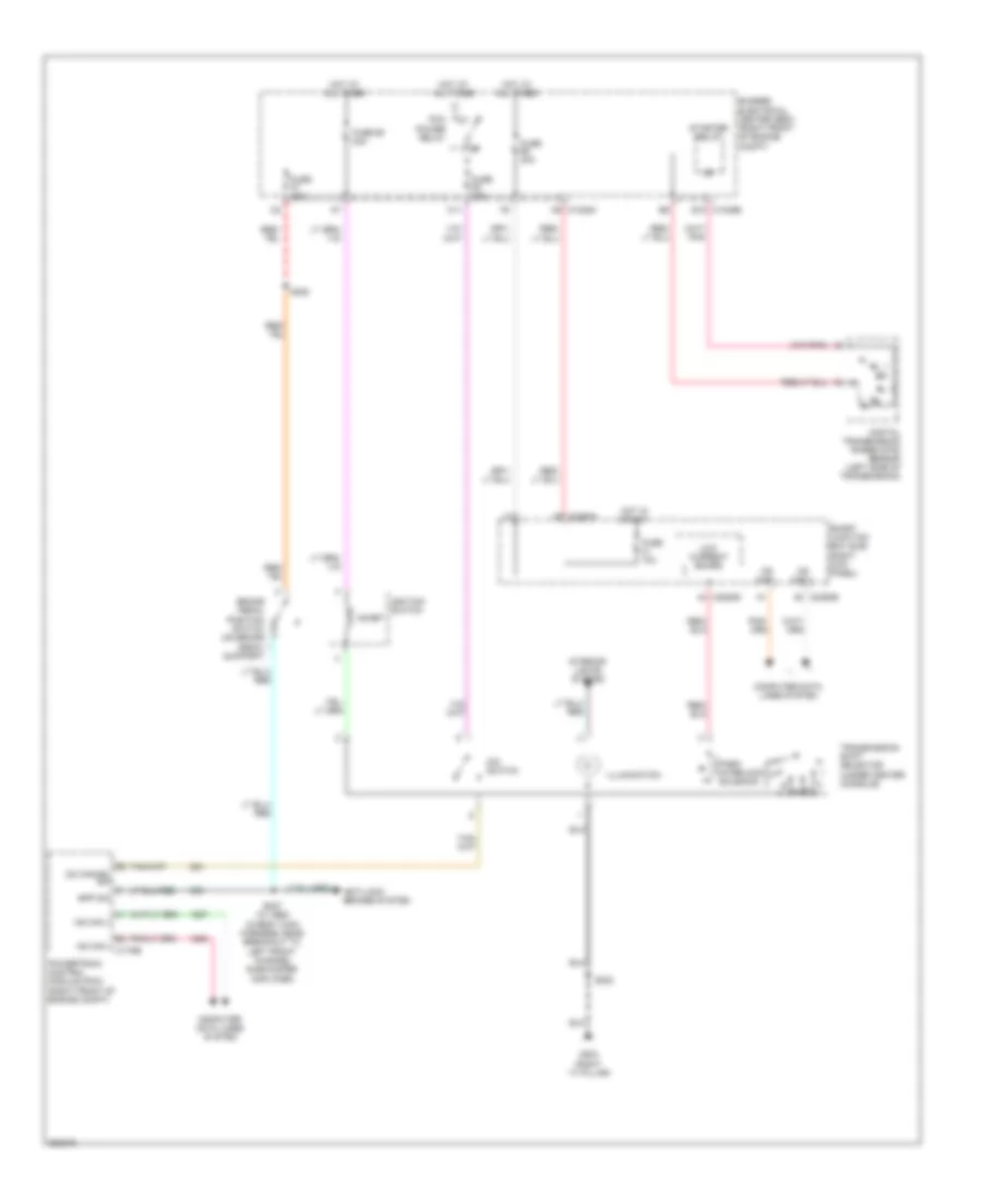
List of elements for Shift Interlock Wiring Diagram for Ford Mustang Shelby GT500KR 2009:
- (right ``a" pillar)
- A9 c1035a
- Anti-lock brakes system
- Bpp sw
- Brake pedal position switch (on brake pedal support)
- Bussed electrical center (bec) (right front of engine
- C1035b e10
- C11
- C2280b
- C2280d
- C2280h
- Compt)
- Computer data lines system
- Digital transmission range (dtr) sensor (left side of transmission)
- Fuse 10a
- Fuse 15a
- Fuse 30a
- Fuse 68 20a
- G203
- Hot at all times
- Hot in start
- Hs can +
- Hs can - c175b
- Ignition switch
- Illumination
- Inhibit
- Interior lights system
- Low current board
- Ms can +
- Ms can -
- O/d switch
- Od cancel sw
- Park interlock solenoid
- Pcm power relay
- Powertrain control module (pcm) (right front of engine compt)
- S222
- S225
- S227 (w/ abs) (in body main harness, near breakout to left front channel subwoofer amplifier)
- Smart junction box (sjb) (right kick panel)
- Starter relay
- Transmission shift selector (under center console)
 Čeština
 Dansk
Dansk Deutsch
 Ελληνικά
 English
 English
 Español
 Français
 Français
 עברית
עברית Hrvatski
 Magyar
 Italiano
 日本語
日本語 한국어
한국어 Nederlands
 Polski
 Português
 Português
 Română
 Русский
 Slovenčina
 Slovenščina
 Svenska
 Türkçe
 中文 (中国)
 Suomi
Suomi