AUTOMOTIVE ELECTRICIANS PORTAL

STARTING/CHARGING – Ford Flex SE 2014 – SYSTEM WIRING DIAGRAMS

STARTING/CHARGING

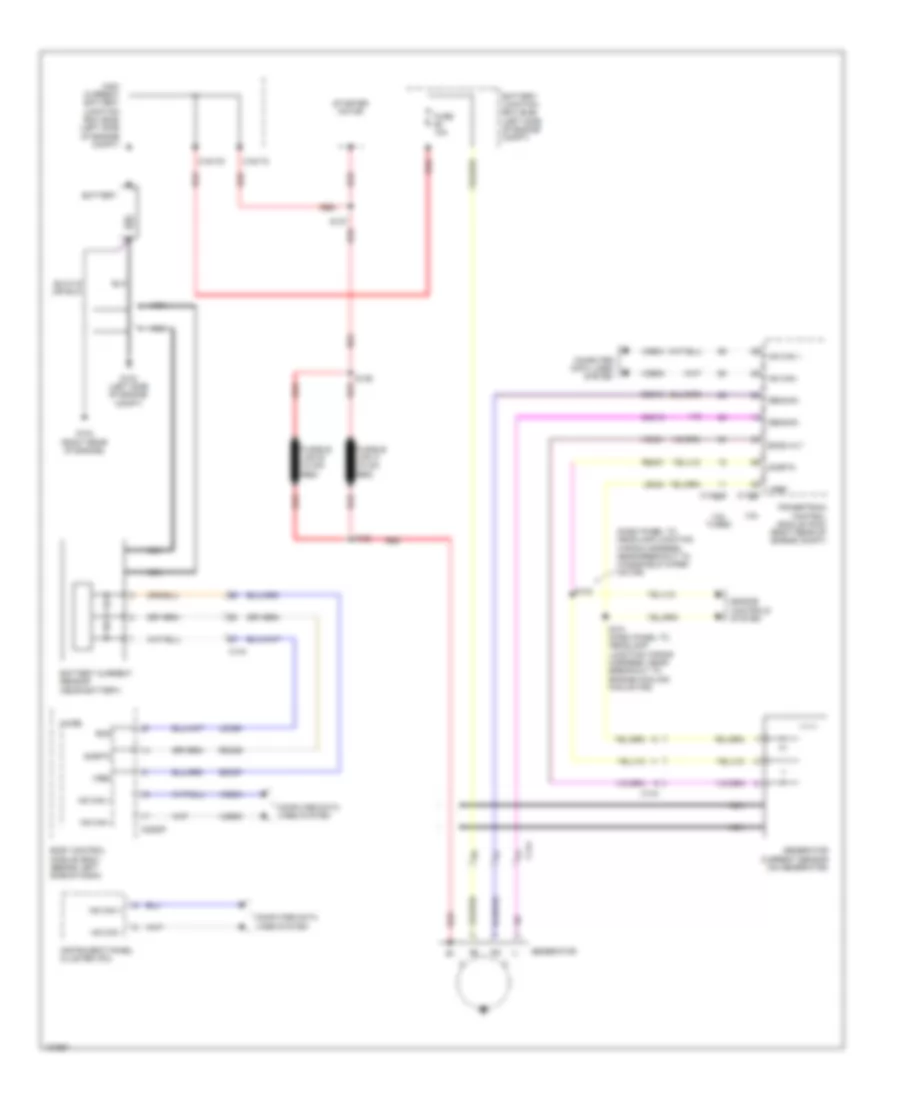
Charging Wiring Diagram for Ford Flex SE 2014

Charging Wiring Diagram for Ford Flex SE 2014 https://portal-diagnostov.com/license.html
https://portal-diagnostov.com/license.html Automotive Electricians Portal FZCO Automotive Electricians Portal FZCO
Download PDF file

List of elements for Charging Wiring Diagram for Ford Flex SE 2014:

  • (engine wiring harness, in breakout to c168 on transmission)
  • 3.5l
  • 3.5l turbo
  • 6f50/6f55 transmission
  • Acc
  • Audio control module (acm) (center of dash)
  • Battery
  • Battery junction box (bjb) (left side of engine compt)
  • Body control module (bcm) (behind left side of dash)
  • C144
  • C1617c
  • C1617d
  • C175b c1381b
  • C175t c1381e
  • C210
  • C2153c
  • C2280b
  • C240a
  • Cdc12
  • Cdc35
  • Ce336
  • Charging circuit
  • Computer data lines system
  • Fuse 26 5a
  • Fuse 30a
  • G103 (left side of engine compt)
  • G104 (right rear of engine)
  • High current battery junction box (bjb) (left side of engine compt)
  • Hot at all times
  • Hs can +
  • Hs can -
  • Ignition switch
  • Lock
  • Micro
  • Ms can +
  • Ms can -
  • Off
  • Powertrain control module (pcm) (right rear of engine compt)
  • Red
  • Remote function actuator module (behind right side of dash)
  • Ret24
  • Run
  • S100
  • S127
  • S207
  • Smc
  • Smcs
  • Start
  • Start/ stop 1 (active high)
  • Start/ stop switch
  • Start/stop 1
  • Starter motor
  • Starter relay
  • Stop 1 start/
  • Tr gnd
  • Tr-1
  • Tr-2
  • Tr-3
  • Tr-4
  • Trs
  • Tss/oss/tr gnd
  • Vdb04
  • Vdb05
  • Vdb06
  • Vdb07
  • Vet29
  • Vet30
  • Vet31
  • Vet32
  • W/ intelligent access
  • W/o intelligent access

Starting Wiring Diagram for Ford Flex SE 2014

Starting Wiring Diagram for Ford Flex SE 2014 https://portal-diagnostov.com/license.html
https://portal-diagnostov.com/license.html Automotive Electricians Portal FZCO Automotive Electricians Portal FZCO
Hanki pääsy kaikkiin auton kytkentäkaavioihinDownload PDF file

List of elements for Starting Wiring Diagram for Ford Flex SE 2014:

  • (dash panel to headlamp junction wiring harness, near breakout to windshield wiper motor)
  • 3.5l
  • 3.5l turbo
  • Battery
  • Battery current sensor (near battery)
  • Battery junction box (bjb) (left side of engine compt)
  • Bcs
  • Bcs2 alt
  • Body control module (bcm) (behind left side of dash)
  • C1381b
  • C144
  • C1617c
  • C1617d
  • C175b
  • C2280f
  • Cdc10
  • Cdc15
  • Computer data lines system
  • Engine controls system
  • Fuse 10a
  • Fusible link a (10 ga- red)
  • Fusible link b (10 ga- red)
  • G103 (left side of engine compt)
  • G104 (right rear of engine)
  • Gencom
  • Generator
  • Generator current sensor (on generator)
  • Genmon
  • High current battery junction box (bjb) (left side of engine compt)
  • Hs can +
  • Hs can -
  • Instrument panel cluster (ipc)
  • Ldc59
  • Le424
  • Micro
  • Nca
  • Powertrain control module (pcm) (right rear of engine compt)
  • Rdc59
  • Re407
  • Red
  • S101 (dash panel to headlamp junction wiring harness, near breakout to engine cooling fan motor)
  • S127
  • S128
  • S129
  • S133
  • Sdc57
  • Sigrtn
  • Starter motor
  • Vdb04
  • Vdb05
  • Vdc61
  • Vref