STARTING/CHARGING
Charging Wiring Diagram for Pontiac G8 GXP 2009
 https://portal-diagnostov.com/license.html
Automotive Electricians Portal FZCO
Automotive Electricians Portal FZCO
https://portal-diagnostov.com/license.html
https://portal-diagnostov.com/license.html
Automotive Electricians Portal FZCO
Automotive Electricians Portal FZCO
List of elements for Charging Wiring Diagram for Pontiac G8 GXP 2009:
- (behind right kick panel)
- (in rear compt, on latch plate) g409
- 175a
- 3.6l
- 5v ref
- 6.0l & 6.2l
- Batt pos vol
- Battery
- Battery cable
- Battery current sensor (left side of rear compt)
- Body control module (bcm) (under left side of dash, right of steering column)
- Charge ind
- Computer data lines system
- Current sig
- Cycle sig
- Driver information center (dic)
- Engine battery cable junction block
- Engine control module (ecm) (right side of engine compt)
- Fuse block
- G201
- G401 (rear compt, on left rear beam)
- Generator
- Generator inline fuse
- Gnd
- Hot at all times
- Hs bus +
- Hs bus -
- I/p battery cable junction block
- Inst/disp/ rfa/dlc fuse 5 10a
- Instrument panel cluster (ipc)
- J221
- J412
- Lo ref
- Lo spd gmlan
- Logic
- Pnk
- Rear fuse block (left side of rear compt)
- Red
- Rvc snsr fuse 11 7.5a
- Starting circuit
- Turn on sig
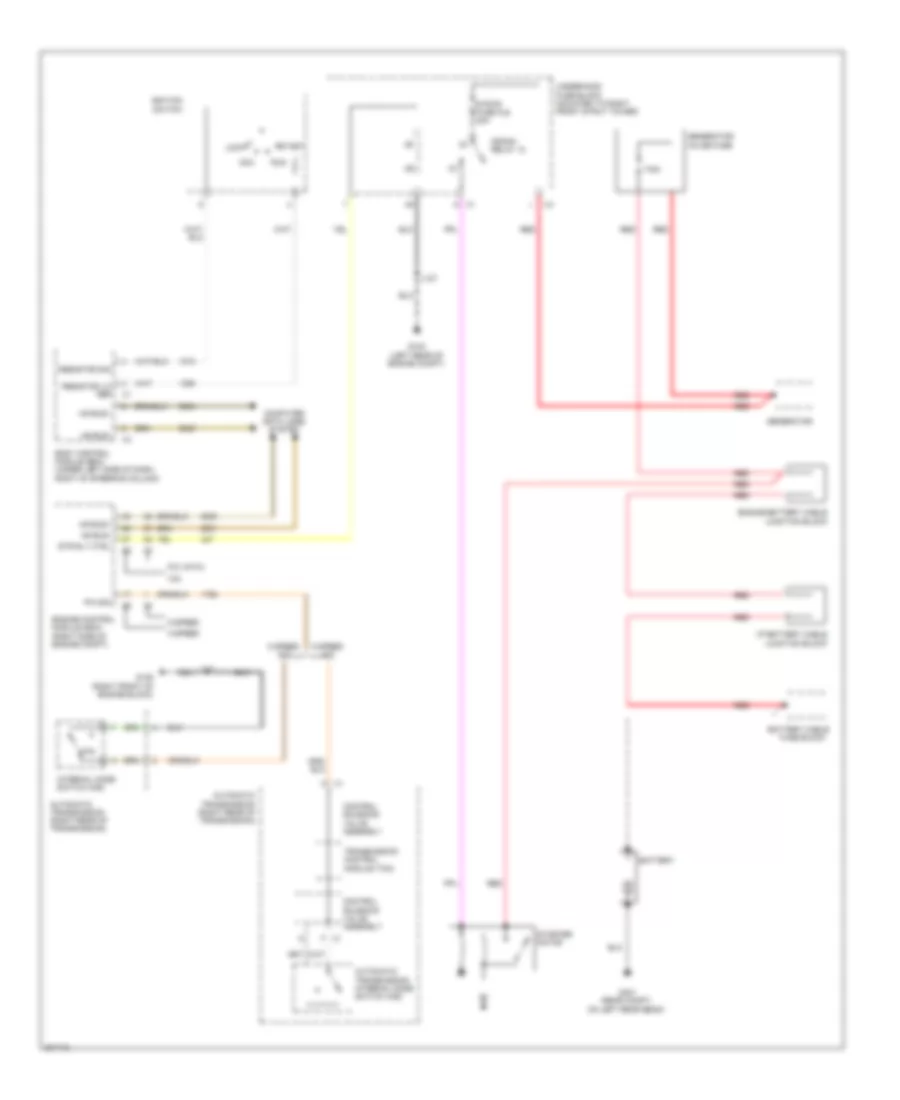
Starting Wiring Diagram for Pontiac G8 GXP 2009
List of elements for Starting Wiring Diagram for Pontiac G8 GXP 2009:
- 175a
- 3.6l
- 5 speed
- 5 speed a/t
- 6 speed
- 6 speed a/t
- 6.0l & 6.2l
- Acc
- Automatic transmission (right rear of transmission)
- Automatic transmission internal mode switch (ims)
- Battery
- Battery cable
- Body control module (bcm) (under left side of dash, right of steering column)
- Computer data lines system
- Control solenoid valve assembly
- Crank relay 12
- Engine battery cable junction block
- Engine control module (ecm) (right side of engine compt)
- F x1
- Fuse block
- G102 (left rear of engine compt)
- G106 (right front of engine block)
- G401 (rear compt, on left rear beam)
- Generator
- Generator inline fuse
- Hs bus+
- Hs bus-
- I/p battery cable junction block
- Ignition switch
- Internal mode switch (ims)
- J122
- J127
- Lock
- P/n
- P/n sig
- Red
- Resistor lo ref
- Resistor sig
- Run
- Start
- Starter motor
- Str rly ctrl
- Strtr fuse fu8 40a
- Transmission control module (tcm)
- Underhood fuse block (mounted to right front strut tower)

 Čeština
 Dansk
Dansk Deutsch
 Ελληνικά
 English
 English
 Español
 Français
 Français
 עברית
עברית Hrvatski
 Magyar
 Italiano
 日本語
日本語 한국어
한국어 Nederlands
 Polski
 Português
 Português
 Română
 Русский
 Slovenčina
 Slovenščina
 Svenska
 Türkçe
 中文 (中国)