SUPPLEMENTAL RESTRAINTS
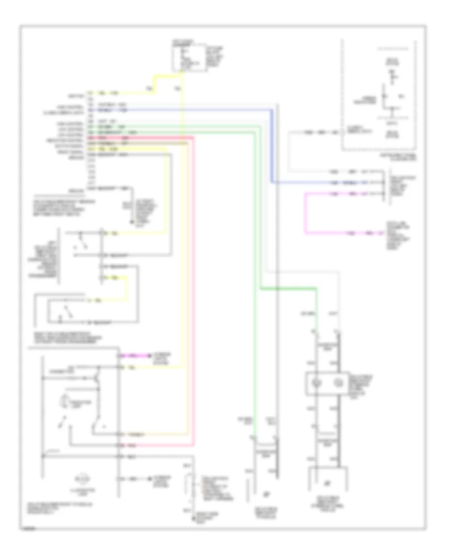
Supplemental Restraint Wiring Diagram for GMC Sonoma 2002
List of elements for Supplemental Restraint Wiring Diagram for GMC Sonoma 2002:
- (at right frame rail, forward of right front wheel) g101
- (no connection)
- (right side of dash) g203
- A10
- A11
- A12
- A13
- A14
- A15
- A16
- A17
- A18
- Airbag indicators
- Class 2 serial data
- Data
- Data link connector (dlc) (partial) (under left side of dash)
- Front signal
- Ground
- High control
- Hot in run & start
- I/p fuse block (on left end of dash)
- Ign
- Ignition
- Illumination lamp
- Indicator control
- Indicator lamp
- Inflatable restraint ip module
- Inflatable restraint ip module disable switch (pickup only)
- Inflatable restraint sensing & diagnostic module (under console & carpet, between front seats)
- Inflatable restraint steering wheel module
- Inflatable restraint steering wheel module coil
- Instrument panel cluster (ipc)
- Interior lights system
- Left inflatable restraint front end discriminating sensor (on front frame crossmember)
- Low control
- Nca
- Pnk
- Right inflatable restraint front end discriminating sensor (on front frame crossmember)
- Shorting bar
- Sir fuse 16 15a
- Solid state
- Splice pack sp201 (on left end of dash)
- Splice pack sp203 (in front of ashtray, strapped to body harness)
- Switch signal
 Čeština
 Dansk
Dansk Deutsch
 Ελληνικά
 English
 English
 Español
 Français
 Français
 עברית
עברית Hrvatski
 Magyar
 Italiano
 日本語
日本語 한국어
한국어 Nederlands
 Polski
 Português
 Português
 Română
 Русский
 Slovenčina
 Slovenščina
 Svenska
 Türkçe
 中文 (中国)
 Suomi
Suomi