ANTI-LOCK BRAKES
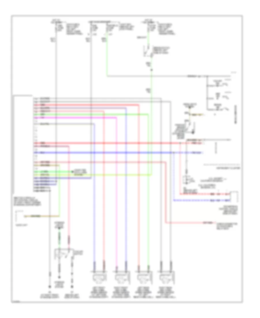
Anti-lock Brakes Wiring Diagram for Mazda 6 s 2005
List of elements for Anti-lock Brakes Wiring Diagram for Mazda 6 s 2005:
- (at right front of engine compt)
- (behind left side of dash)
- 2.3l: california emission, 3.0l
- 2.3l: except california emission
- Abs fuse 60a
- Abs ind
- Abs/tcs hydraulic unit/control module (at right front corner of engine compartment)
- Audio unit
- Brake ind
- Brake switch (behind left
- Check connector (in main fuse & relay box)
- Computer data lines system
- G2 (behind left end of dash)
- Headlights system
- Hot at all times
- Hot in on or start
- Ill
- Instrument cluster
- Interior lights system
- J-01
- J-02
- Jc g-02
- Joint box (behind left kick panel)
- Left front abs wheel speed sensor (at left side of engine compt)
- Left rear abs wheel speed sensor (at left rear wheelwell)
- Main fuse & relay box (on left front inner fender panel)
- Meter ig fuse 15a
- Micro-computer
- Parking brake switch (at base of parking brake lever)
- Powertrain control module (behind left side of dash)
- Red
- Right front abs wheel speed sensor (at right side of engine compt)
- Right rear abs wheel speed sensor (at right rear wheelwell)
- Sas fuse 15a
- Side of dash)
- Stop fuse 15a
- Tcs off ind
- Tcs off switch
 Čeština
 Dansk
Dansk Deutsch
 Ελληνικά
 English
 English
 Español
 Français
 Français
 עברית
עברית Hrvatski
 Magyar
 Italiano
 日本語
日本語 한국어
한국어 Nederlands
 Polski
 Português
 Português
 Română
 Русский
 Slovenčina
 Slovenščina
 Svenska
 Türkçe
 中文 (中国)
 Suomi
Suomi