ANTI-LOCK BRAKES
Anti-lock Brakes Wiring Diagram for Mazda B3000 2006
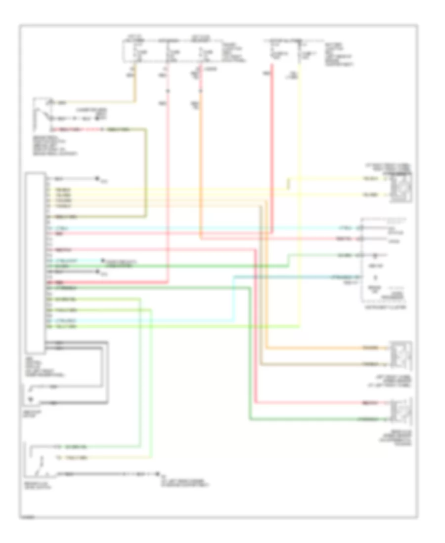
List of elements for Anti-lock Brakes Wiring Diagram for Mazda B3000 2006:
- (at right front wheel) right front wheel speed sensor
- (under driver's seat) g10
- 0922-101
- 4x4 status
- Abs control module (on left front inner fender panel)
- Abs ind
- Abs pump motor
- Battery junction box (left rear of engine compartment)
- Brake fluid level switch
- Brake ind
- Brake pedal position switch (behind left side of dash, on brake pedal support)
- Computer data lines system
- Fuse 10a
- Fuse 17 40a
- Fuse 33 30a
- Fuse 5a
- G12
- G3 (at left rear corner of engine compartment)
- Hot at all times
- Hot in on or start
- Hot in run
- Instrument cluster
- J-2280b
- Left front wheel speed sensor (at left front wheel)
- Micro- processor
- Nca
- Rear axle speed sensor (on differential housing)
- Red
- Red red
- Red/pnk
- Smart junction box (at right kick panel)
- Vpwr
 Čeština
 Dansk
Dansk Deutsch
 Ελληνικά
 English
 English
 Español
 Français
 Français
 עברית
עברית Hrvatski
 Magyar
 Italiano
 日本語
日本語 한국어
한국어 Nederlands
 Polski
 Português
 Português
 Română
 Русский
 Slovenčina
 Slovenščina
 Svenska
 Türkçe
 中文 (中国)
 Suomi
Suomi