WARNING SYSTEMS
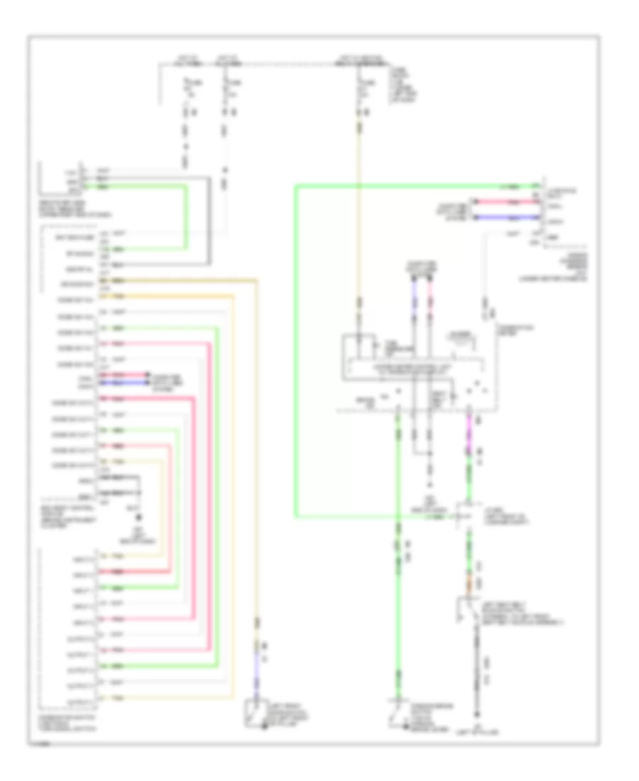
Warning Systems Wiring Diagram for Nissan Altima 2014
List of elements for Warning Systems Wiring Diagram for Nissan Altima 2014:
- (left "b" pillar)
- +12v
- 12g
- 12r
- 77j
- 82j
- Air bag diagnosis sensor unit (under center console)
- B12
- B201
- Bat bcm fuse
- Bcm (body control module) (behind instrument cluster)
- Brake ind
- Buzzer
- Can-h
- Can-l
- Combi sw in 1
- Combi sw in 2
- Combi sw in 3
- Combi sw in 4
- Combi sw in 5
- Combi sw out 1
- Combi sw out 2
- Combi sw out 3
- Combi sw out 4
- Combi sw out 5
- Combination meter
- Combination switch (lighting & turn signal switch)
- Computer data lines system
- Dr door sw
- E30
- Fuse 10a
- Fuse 5a
- Fuse block (j/b) (lower left end of dash)
- Gnd
- Gnd 1
- Gnd 2
- Gnd rf a/l
- Hot at all times
- Hot w/ ignition relay 2 energized
- Input 1
- Input 2
- Input 3
- Input 4
- Input 5
- J/c b05 (left front of luggage compt)
- Left front door switch (in left front "b" pillar)
- Left seat belt buckle switch (integral to left front seat belt buckle assembly)
- Lh buckle sw(+)
- M17
- M18
- M19
- M20
- M21
- M24
- M35
- M57 (left end of dash)
- Output 1
- Output 2
- Output 3
- Output 4
- Output 5
- Parking brake switch (top of parking brake lever)
- Pnk
- Red
- Remote keyless entry receiver (upper right end of dash)
- Rf nimoco
- Sbr
- Seat belt ind
- Sig
- Tan
- Tire pressure ind
- Unified meter control unit (w/ information display)
 Čeština
 Dansk
Dansk Deutsch
 Ελληνικά
 English
 English
 Español
 Français
 Français
 עברית
עברית Hrvatski
 Magyar
 Italiano
 日本語
日本語 한국어
한국어 Nederlands
 Polski
 Português
 Português
 Română
 Русский
 Slovenčina
 Slovenščina
 Svenska
 Türkçe
 中文 (中国)
 Suomi
Suomi