ANTI-LOCK BRAKES
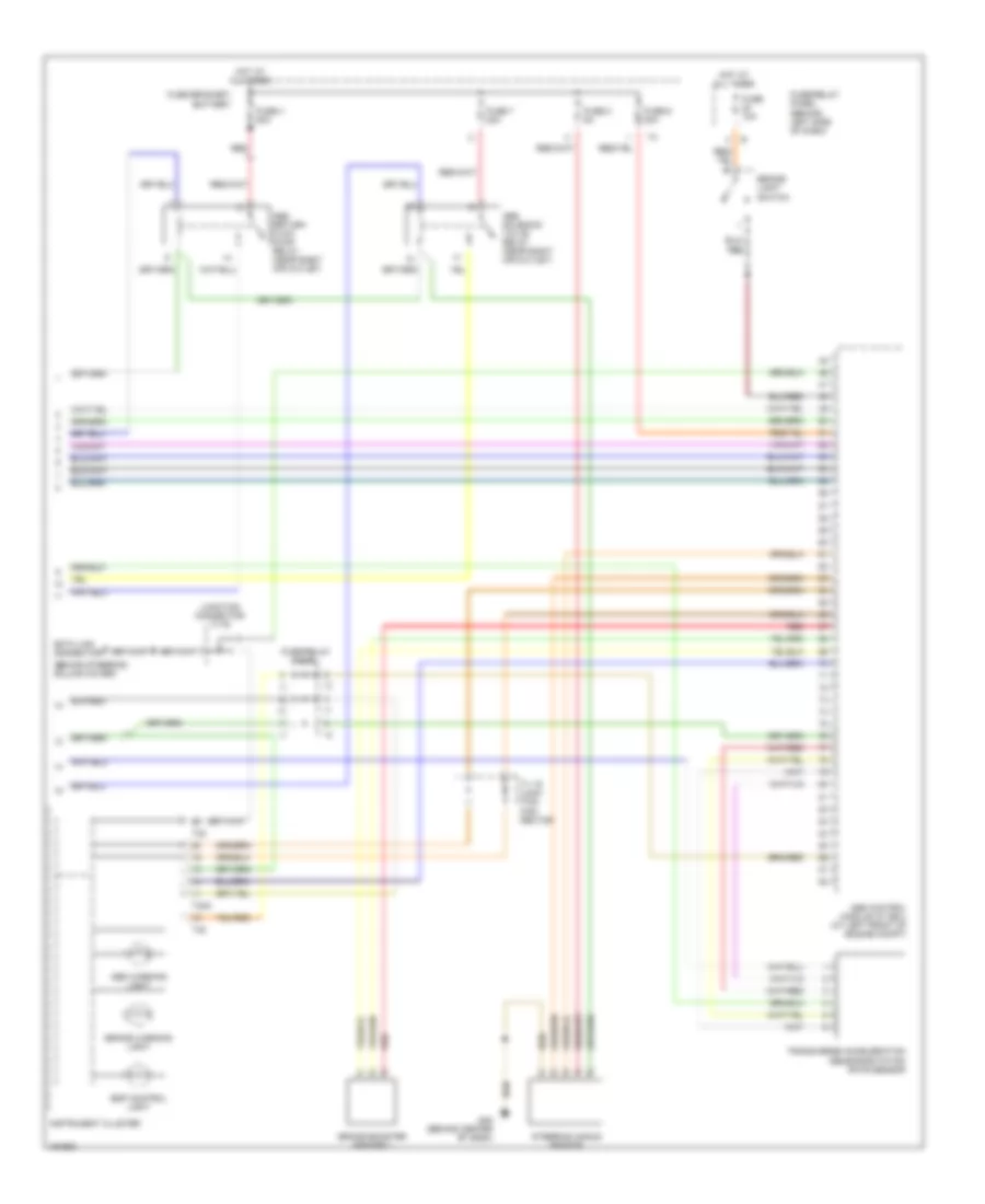
Anti-lock Brake Wiring Diagrams, with Electronic Stability Program (1 of 2) for Volkswagen EuroVan MV 2002
 https://portal-diagnostov.com/license.html
Automotive Electricians Portal FZCO
Automotive Electricians Portal FZCO
https://portal-diagnostov.com/license.html
https://portal-diagnostov.com/license.html
Automotive Electricians Portal FZCO
Automotive Electricians Portal FZCO
List of elements for Anti-lock Brake Wiring Diagrams, with Electronic Stability Program (1 of 2) for Volkswagen EuroVan MV 2002:
- Abs control module (w/ edl) (at left front of engine compt)
- Abs rtn flow pump
- Abs valves
- Asr/esp switch
- Battery
- Cruise control system
- Fuse 14 10a
- Fuse/relay panel
- Fuse/relay panel (behind left side of dash)
- G1 (battery to body)
- G45 (behind center of dash)
- Hot in on or start
- Interior lights system
- Left front abs wheel speed sensor
- Left rear abs wheel speed sensor
- Lf in
- Lf out
- Lr in
- Lr out
- Parking brake warning light switch
- Red
- Rf in
- Rf out
- Right front abs wheel speed sensor
- Right rear abs wheel speed sensor
- Rr in
- Rr out
- Tc pil
- Traction control hydraulic pump
- Tv 5 junction connector
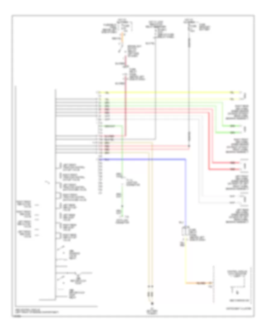
Anti-lock Brake Wiring Diagrams, with Electronic Stability Program (2 of 2) for Volkswagen EuroVan MV 2002
List of elements for Anti-lock Brake Wiring Diagrams, with Electronic Stability Program (2 of 2) for Volkswagen EuroVan MV 2002:
- (behind steering column cover)
- Abs control module (w/ edl) (at left front of engine compt)
- Abs return flow pump relay (near right air outlet)
- Abs solenoid valve relay (near right air outlet)
- Abs warning light
- Brake booster sender 1
- Brake warning light
- Brake- light switch
- Data link connector
- Esp control light
- Fuse 10a
- Fuse 4 50a
- Fuse 6 30a
- Fuse 7 30a
- Fuse 8 5a
- Fuse bracket/ battery
- Fuse/relay panel
- Fuse/relay panel (behind left side of dash)
- G45 (behind center of dash)
- Hot at all times
- Instrument cluster
- Junction connector tv16
- Red
- Steering angle sensor
- T32
- T32a
- Transverse acceleration sensor/rotation rate sensor
- Tv 16 junc- tion con- nector
Anti-lock Brake Wiring Diagrams, without Electronic Stability Program for Volkswagen EuroVan MV 2002
List of elements for Anti-lock Brake Wiring Diagrams, without Electronic Stability Program for Volkswagen EuroVan MV 2002:
- Abs control module (left front of engine compartment)
- Abs return flow pump
- Abs return flow pump relay
- Abs solenoid valve relay
- Abs warning ind
- Brakelight switch (below left side of dash)
- Control module with indicator unit
- Data link connector
- Fuse 10a
- Fuse 5 10a (below fuse/ relay panel)
- Fuse 50a
- Fuse bracket/ battery
- Fuse/ relay panel (behind left side of dash)
- Fuse/relay panel (behind left side of dash)
- G1 (battery to body)
- Hot at all times
- Hot w/ load reduction relay energized
- Instrument cluster
- Left front abs inlet valve
- Left front abs outlet valve
- Left front abs wheel speed sensor (on front of left front wheel bearing assembly)
- Left front traction control outlet valve
- Left front traction control switch-over valve
- Left rear abs inlet valve
- Left rear abs outlet valve
- Left rear abs wheel speed sensor (on back of left rear wheel bearing assembly)
- Red
- Right front abs inlet valve
- Right front abs outlet valve
- Right front abs wheel speed sensor (on front of right front wheel bearing assembly)
- Right front traction control outlet valve
- Right front traction control switch-over valve
- Right rear abs inlet valve
- Right rear abs outlet valve
- Right rear abs wheel speed sensor (on back of right rear wheel bearing assembly)
- T16
- T32
- Tv 14 junction connector

 Čeština
 Dansk
Dansk Deutsch
 Ελληνικά
 English
 English
 Español
 Français
 Français
 עברית
עברית Hrvatski
 Magyar
 Italiano
 日本語
日本語 한국어
한국어 Nederlands
 Polski
 Português
 Português
 Română
 Русский
 Slovenčina
 Slovenščina
 Svenska
 Türkçe
 中文 (中国)