COOLING FAN
2.8L
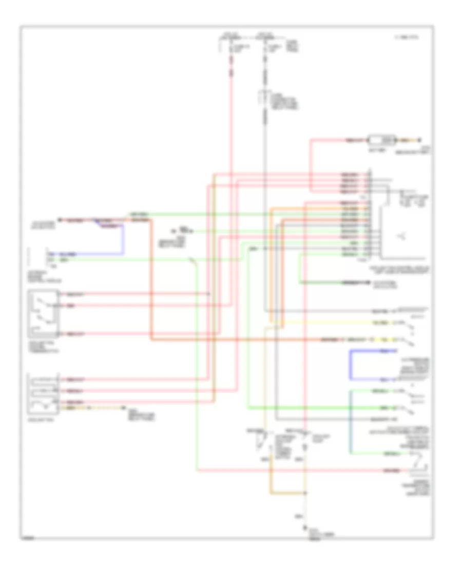
2.8L, Cooling Fan Wiring Diagram for Volkswagen GTI VR6 1995
List of elements for 2.8L, Cooling Fan Wiring Diagram for Volkswagen GTI VR6 1995:
- 1995 vftc c
- A/c cut out thermal switch/third speed coolant
- A/c pressure switch (right side of engine compt)
- A/c system (a/c clutch)
- A/c system (a/c switch)
- A1/5
- After-run coolant fan control thermo- switch
- Ambient temperature switch (near horn)
- Battery
- Coolant fan
- Coolant fan control module (left side of engine compt)
- Coolant fan control thermoswitch
- Coolant pump
- D/3
- Fan switch (center of engine compt)
- Fuse 19 30a
- Fuse 30a
- Fuse 4 15a
- Fuse 50a
- Fuse/ relay panel
- G100 (behind battery)
- G133 (on cylinder head)
- G202 (beside fuse/ relay panel)
- Hot at all times
- Motronic engine control module
- Red
- T10a
- T41
- T68
- Wire connector (above fuse/ relay panel)
 Čeština
 Dansk
Dansk Deutsch
 Ελληνικά
 English
 English
 Español
 Français
 Français
 עברית
עברית Hrvatski
 Magyar
 Italiano
 日本語
日本語 한국어
한국어 Nederlands
 Polski
 Português
 Português
 Română
 Русский
 Slovenčina
 Slovenščina
 Svenska
 Türkçe
 中文 (中国)
 Suomi
Suomi