ENGINE PERFORMANCE
3.2L
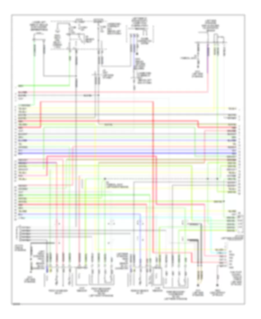
3.2L, Engine Performance Wiring Diagram, A/T (1 of 5) for Acura TL 2007
 https://portal-diagnostov.com/license.html
Automotive Electricians Portal FZCO
Automotive Electricians Portal FZCO
https://portal-diagnostov.com/license.html
https://portal-diagnostov.com/license.html
Automotive Electricians Portal FZCO
Automotive Electricians Portal FZCO
List of elements for 3.2L, Engine Performance Wiring Diagram, A/T (1 of 5) for Acura TL 2007:
- (left side of dash) j/c c507
- (near brake pedal) brake pedal position switch
- (type s)
- (under middle of dash) j/c c512
- Acc
- Afshtcr
- Air conditioning system
- Anti-theft system
- App sensor (right side of engine compt)
- Apsa
- Apsb
- Atpn
- B10
- B11
- B12
- B13
- B14
- B15
- B16
- B17
- B18
- B19
- B20
- B21
- B22
- B23
- B24
- Bksw
- Bkswnc
- Braided
- Canh
- Canl
- Ckpa
- Ckpb
- Cmp
- Computer data lines system
- Cooling fans system
- E10
- E11
- E12
- E13
- E14
- E15
- E16
- E17
- E18
- E19
- E20
- E21
- E22
- E23
- E24
- E25
- E26
- E27
- E28
- E29
- E30
- E31
- Ect2
- Egr
- Eld
- Etcsrly
- Except type s
- Fanh
- Fanl
- Fpc
- Fpcd
- Ftp
- Fuse 15a
- Fuse 2 15a
- Fuse 20a
- G101 (left side of engine)
- Hot at all times
- Hot in on or start
- Ig1
- Ignition coil relay
- Imocd
- Imofpr
- Imt+
- Imt-
- Imtm
- Ipb1
- Ipb2
- Knock sensor (on top middle of engine, below intake manifold)
- Lg2
- Mcs
- Moonroof control unit (rear of roof)
- Mrly
- Navigation unit (if equipped) (in trunk, below left side of package tray)
- Pcm (behind center of dash)
- Pcs
- Pgm-fi main relay 1
- Pgm-fi main relay 2
- Pnk
- Pspsw
- Red
- Scs
- Sdn
- Sg3
- Sg4
- Shift inter- lock system
- Sho2sb1
- Sho2sb2
- Sls
- Smode
- Sound systems
- Starting/charging system
- Strld
- Strly
- Sts
- Sup
- Throttle actuator control module relay (behind glove box)
- To fuse 23 (diagram 3 of 5)
- Type s
- Under- dash fuse/ relay box (behind left end of dash)
- Under-hood fuse/relay box (left rear of engine compt)
- Vcc3
- Vcc4
- Vcentb1
- Vcentb2
- Vsb1
- Vsb2
- Vsp
- Vssout
- Vsv
- Wen
- X23
- X31
- X32
- X38
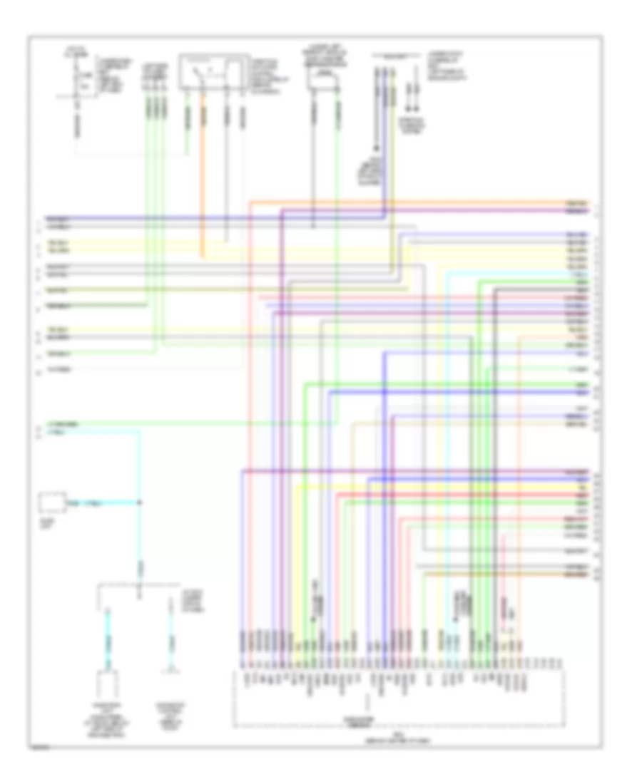
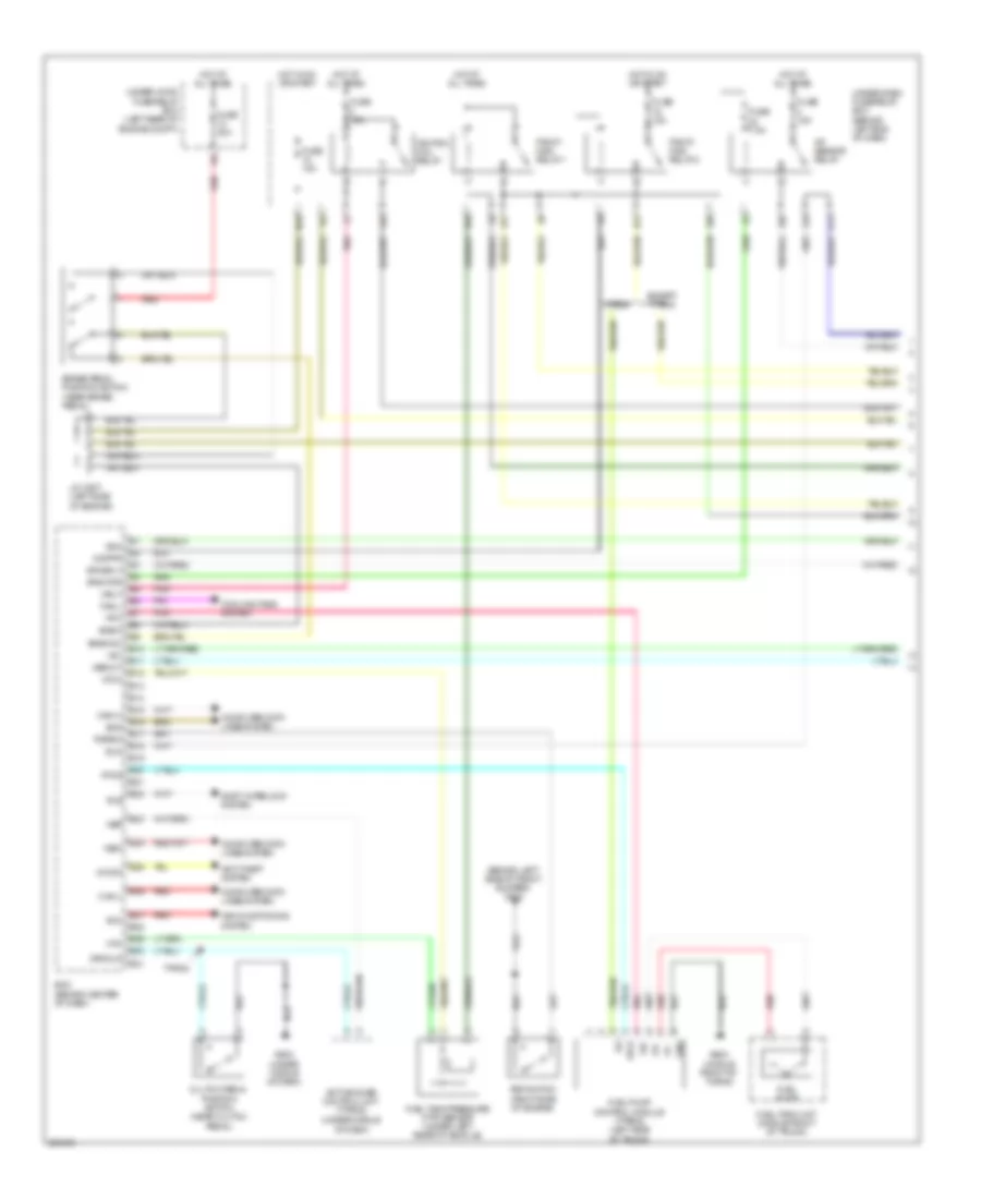
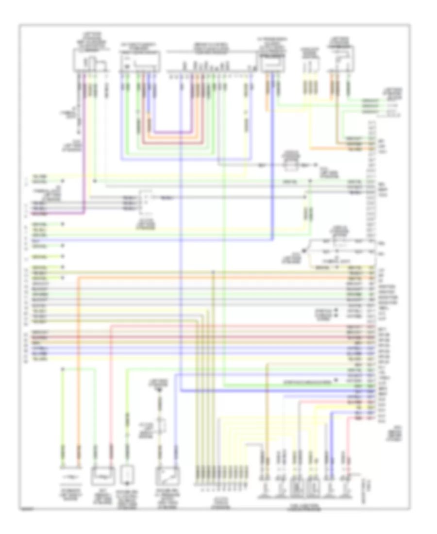
3.2L, Engine Performance Wiring Diagram, A/T (2 of 5) for Acura TL 2007
List of elements for 3.2L, Engine Performance Wiring Diagram, A/T (2 of 5) for Acura TL 2007:
- (at left side of engine compt, near strut tower) evap canister purge valve
- (left rear of engine) engine mount control solenoid valve
- (left side of dash) j/c c508
- (left side of engine)
- (left side of engine) j/c c105
- (middle front of trunk) fuel tank unit
- (right side of engine) psp switch
- (under left rear of vehicle) fuel tank pressure (ftp) sensor
- Atf temperature sensor
- E16
- Ect sensor 2 (under front of engine compt)
- Except type s
- Fuel gauge sending unit
- Fuel pump
- G101 (left side of engine)
- G302 (behind left side of front bumper)
- G503 (under middle of dash)
- G603 (middle front of trunk)
- Imt actuator (right side of engine)
- Instrument cluster system
- J/c c105
- J/c c105 (left side of engine)
- J/c c106 (middle of engine)
- Map sensor (left side of engine)
- Output shaft (countershaft) speed sensor (in transmission housing)
- Pg2
- Pnk
- Red
- Sedf
- Sefd
- Sequential sportshift a/t shift switch
- Sequential sportshift mode switch
- Throttle actuator control module (behind glove box)
- Tp sensor/ throttle actuator (on throttle body)
- Tpsa
- Tpsb
- Transmission gear selection switch/ park pin switch/ a/t gear position indicator panel light (under center console)
- Type s
- Under-dash fuse/relay box (behind left end of dash) x5
- Vcc
3.2L, Engine Performance Wiring Diagram, A/T (3 of 5) for Acura TL 2007
List of elements for 3.2L, Engine Performance Wiring Diagram, A/T (3 of 5) for Acura TL 2007:
- (b1, s1) connector
- (left front of engine) front a/f sensor (b2, s1) connector
- (left rear of engine compt) under-hood fuse/relay box
- (left side of engine) egr valve & egr valve position sensor
- (under left rear of vehicle) evap canister vent shut valve
- A/f sensor relay
- Braided
- Chip resistor
- D13
- Eld unit
- Fp+
- Fp-
- Fpc
- Fpcd
- From pgm fi main relay 1 (diagram 1 of 5)
- Front a/f sensor (b2, s1)
- Front secondary ho2s sensor (b2, s2) (left front of engine)
- Fuel pump control module (type s) (left side of trunk)
- Fuse 15a
- Fuse 4 15a
- Fuse 7.5a
- G101 (left side of engine)
- G302 (behind left side of front bumper)
- G603 (middle front of trunk)
- Gnd
- Hot at all times
- Hot in on or start
- Ig1
- J/c c104 (middle of engine)
- J/c c105 (left side of engine)
- J/c c507 (left side of dash)
- N29
- Pnk
- Power distribution system
- Rear a/f sensor (b1, s1)
- Rear secondary ho2s sensor (b1, s2) (left rear of engine)
- Red
- S1 (thermal joint)
- S3 (thermal joint) (left side of engine)
- Under-dash fuse/relay box (behind left end of dash)
- X10
- X36
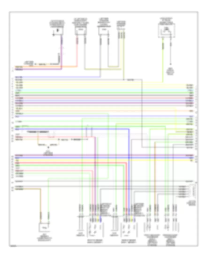
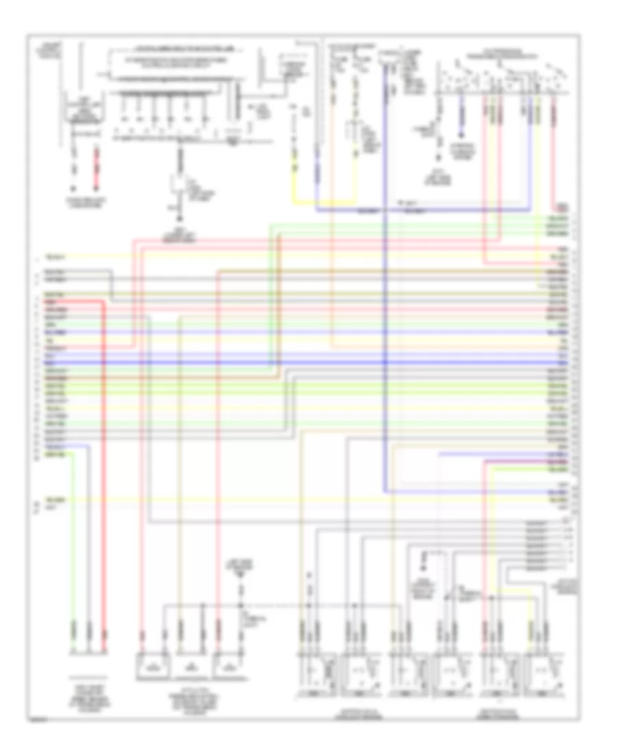
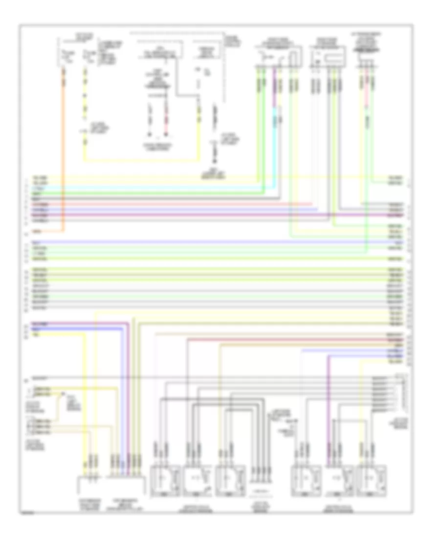
3.2L, Engine Performance Wiring Diagram, A/T (4 of 5) for Acura TL 2007
List of elements for 3.2L, Engine Performance Wiring Diagram, A/T (4 of 5) for Acura TL 2007:
- (left side of engine)
- (left side of engine) g101
- (on transaxle) transmission range switch
- A/t clutch pressure control solenoid valves (on transmission housing)
- A/t gear ind/cruise control dimming circuit
- A/t gear position detection circuit
- A/t gear position ind drive circuit
- A/t gear position indicator brightness control & dimming circuit
- A11
- A13
- A14
- B10
- B18
- Computer data lines system
- Cpu/fail safe circuit/can controller
- Drive circuit
- Fast controller area network transceiver
- Fuse 7.5a
- G101
- G102 (on right front of engine)
- G501 (under left side of dash)
- Gauge control module
- Hot in on or start
- Icm
- Ignition coils (middle of engine)
- Ignition coils (rear of engine)
- Input shaft (mainshaft) speed sensor (in transmission housing)
- J/c c104 (middle of engine)
- J/c c506 (left side of dash)
- J/c c508 (left side of dash)
- Lcd back light
- Micu
- Mil ind
- P16
- P20
- Red
- S1 (thermal joint)
- S2 (thermal joint)
- Shift ind
- Starting/ charging system
- Under- dash fuse/ relay box (behind left end of dash)
- Warning drive circuit
- X20
- X34
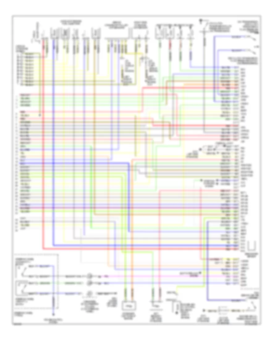
3.2L, Engine Performance Wiring Diagram, A/T (5 of 5) for Acura TL 2007
List of elements for 3.2L, Engine Performance Wiring Diagram, A/T (5 of 5) for Acura TL 2007:
- (behind crankshaft pulley) ckp sensors
- (middle of engine) fuel injectors
- (middle of engine) j/c c104
- (on transmission) 2nd clutch transmission fluid pressure switch
- (right side of engine) cmp sensor
- (thermal joint) s2
- 3rd clutch transmission fluid pressure switch (on transmission)
- 4th clutch transmission fluid pressure switch (on transmission)
- A10
- A11
- A12
- A13
- A14
- A15
- A16
- A17
- A18
- A19
- A20
- A21
- A22
- A23
- A24
- A25
- A26
- A27
- A28
- A29
- A30
- A31
- Afshtcb1
- Afshtcb2
- Altc
- Altf
- Altl
- Atft
- Atpd
- Atpfwd
- Atpl
- Atpp
- Atpr
- Atprvs
- B15
- Barometer sensor
- C10
- C11
- C12
- C13
- C14
- C15
- C16
- C17
- C18
- C19
- C20
- C21
- C22
- Cable reel (b: on steering column) (c: on steering wheel)
- Cruise control system
- D10
- D11
- D12
- D13
- D14
- D15
- D16
- D17
- Ect 1
- Ect sensor 1 (left side of engine)
- Egrp
- Engine) g101
- Except type s
- G101 (left side of engine)
- G501 (under left side of dash)
- Iat
- Iat sensor (left side of engine)
- Igp
- Igpls1
- Igpls2
- Igpls3
- Igpls4
- Igpls5
- Igpls6
- Inj1
- Inj2
- Inj3
- Inj4
- Inj5
- Inj6
- J/c c105 (left side of engine)
- J/c c106 (middle of engine)
- Lg1
- Lsa
- Lsb
- Lsc
- Map
- Op2sw
- Op3sw
- Op4sw
- Pcm (behind center of dash)
- Pg1
- Pg2
- Ppin
- Red
- Rocker arm oil control solenoid (right side of engine)
- Rocker arm oil pressure switch (right side of engine)
- Sdnp
- Sedf
- Sefd
- Sg1
- Sg2
- Sha
- Shb
- Shc
- Shd
- Shift control solenoid valves
- Shift interlock system
- So2shtcb1
- So2shtcb2
- Starting/ charging system
- Steering wheel (type s)
- Steering wheel downshift (-) switch
- Steering wheel upshift (+) switch
- Supp
- Type s
- Vbsol
- Vbsol2
- Vcc1
- Vcc2
- Vlblb1
- Vlblb2
- Vtpsw
- Vts
3.2L, Engine Performance Wiring Diagram, M/T (1 of 5) for Acura TL 2007
List of elements for 3.2L, Engine Performance Wiring Diagram, M/T (1 of 5) for Acura TL 2007:
- (behind left side of front bumper) g302
- A/f sensor relay
- Acc
- Active noise control unit (type s) (under middle
- Afshtcr
- Air conditioning system
- Anti-theft system
- Bksw
- Bkswnc
- Brake pedal position switch (near brake pedal)
- Can-h
- Can-l
- Clutch pedal position switch (near clutch pedal)
- Computer data lines system
- Cooling fans system
- Crmcls
- D13
- E10
- E11
- E12
- E13
- E14
- E15
- E16
- E17
- E18
- E19
- E20
- E21
- E22
- E23
- E24
- E25
- E26
- E27
- E28
- E29
- E30
- E31
- Ecm (behind center of dash)
- Eld
- Etcsrly
- Except type s
- Fan-l
- Fp+
- Fp-
- Fpc
- Fpcd
- Ftp
- Fuel pump
- Fuel pump control module (type s) (left side of trunk)
- Fuel tank pressure (ftp) sensor (under left rear of vehicle)
- Fuel tank unit (middle front of trunk)
- Fuse 15a
- Fuse 20a
- Fuse 7.5a
- G503 (under middle of dash)
- G603 (middle front of turnk)
- Gnd
- Hot at all times
- Hot in on or start
- Ig1
- Ignition coil relay
- Imocd
- Imofpr
- J/c c507 (left side of engine)
- Mrly
- N29
- Nep
- Of dash)
- Pgm-fi main relay 1
- Pgm-fi main relay 2
- Pnk
- Psp switch (right side of engine)
- Pspsw
- Red
- Rvs
- Scs
- Sg4
- Shift interlock system
- Type s
- Under-dash fuse/relay box (behind left end of dash)
- Under-hood fuse/relay box (left rear of engine compt)
- Vcc4
- Vssout
- Vsv
- Wen
- X10
- X31
- X32
- X36
- X38
3.2L, Engine Performance Wiring Diagram, M/T (2 of 5) for Acura TL 2007
List of elements for 3.2L, Engine Performance Wiring Diagram, M/T (2 of 5) for Acura TL 2007:
- (left side of dash) j/c c508
- (under left rear of vehicle) evap canister vent shut valve
- Apsa
- Apsb
- Audio unit
- B10
- B11
- B12
- B13
- B14
- B15
- B16
- B17
- B18
- B19
- B20
- B21
- B22
- B23
- B24
- Barometer sensor
- C26
- Ckpa
- Ckpb
- Cmp
- Cooling fans system
- D10
- D11
- D12
- D13
- D14
- D15
- D16
- D17
- Ecm (behind center of dash)
- Ect2
- Egr
- Eld unit
- Fan-h
- Fuse 15a
- G302 (behind left side of front bumper)
- Hot at all times
- Ig1
- Imt+
- Imt-
- Imtm
- Ipb1
- Ipb2
- J/c c512 (under middle of dash)
- Lg2
- Mcs
- Moonroof control unit (rear of roof)
- Navigation unit (if equipped) (in trunk, below left side of package tray)
- Pcs
- Red
- Sg3
- Sho2sb1
- Sho2sb2
- Starting/ charging system
- Sts
- System charging starting/
- Throttle actuator control module relay (behind glove box)
- Under-dash fuse/relay box (behind left end of dash)
- Under-hood fuse/relay box (left rear of engine compt)
- Vbsol2
- Vcc3
- Vcentb1
- Vcentb2
- Vlblb1
- Vlblb2
- Vsb1
- Vsb2
- X23
3.2L, Engine Performance Wiring Diagram, M/T (3 of 5) for Acura TL 2007
List of elements for 3.2L, Engine Performance Wiring Diagram, M/T (3 of 5) for Acura TL 2007:
- (at left side of engine compt, near strut tower) evap canister purge valve
- (left rear of engine) engine mount control solenoid valve
- (left side of engine) g101
- (left side of engine) j/c c105
- (middle front of trunk) (except type s) fuel tank unit
- (on top middle of engine, below intake manifold) knock sensor
- Braided
- Chip resistor
- Ect sensor 2 (under front of engine compt)
- Front a/f sensor (bank 2, sensor 1)
- Front secondary ho2s sensor (bank 2, sensor 2) (left front of engine)
- Fuel pump
- G101 (left side of engine)
- G603 (middle front of trunk)
- J/c c106 (middle of engine)
- Rear a/f sensor (bank 1, sensor 1)
- Rear secondary ho2s sensor (bank 1, sensor 2) (left rear of engine)
- Red
3.2L, Engine Performance Wiring Diagram, M/T (4 of 5) for Acura TL 2007
List of elements for 3.2L, Engine Performance Wiring Diagram, M/T (4 of 5) for Acura TL 2007:
- (in transmission housing) input shaft (mainshaft) speed sensor
- (left side of engine) g101
- (right side of engine compt) app sensor
- (right side of engine) imt actuator
- A13
- A14
- B10
- B18
- Ckp sensors (behind crankshaft pulley)
- Cmp sensor (right side of engine)
- Computer data lines system
- Cpu/ fail safe circuit/ can controller
- Fast controller area network transceiver
- Fuse 7.5a
- G101 (left side of engine)
- G501 (under left side of dash)
- Gauge control module
- Hot in on or start
- Icm
- Ignition coils (middle of engine)
- Ignition coils (rear of engine)
- J/c c104 (middle of engine)
- J/c c105 (left side of engine)
- J/c c106 (middle of engine)
- J/c c506 (left side of dash)
- J/c c508 (left side of dash)
- Mil ind
- Red
- S1 (thermal joint)
- Under-dash fuse/relay box (behind left end of dash)
- Warning drive circuit
- X20
- X34
3.2L, Engine Performance Wiring Diagram, M/T (5 of 5) for Acura TL 2007
List of elements for 3.2L, Engine Performance Wiring Diagram, M/T (5 of 5) for Acura TL 2007:
- (behind glove box) throttle actuator control module
- (in transmission housing) output shaft (countershaft) speed sensor
- (left side of engine) egr valve & egr valve position sensor
- (left side of engine) g101
- (left side of engine) j/c c105
- (left side of engine) map sensor
- (middle of engine) j/c c104
- (on throttle body) tp sensor/ throttle actuator
- A10
- A11
- A12
- A13
- A14
- A15
- A16
- A17
- A18
- A19
- A20
- A21
- A22
- A23
- A24
- A25
- A26
- A27
- A28
- A29
- A30
- A31
- Afshtcb1
- Afshtcb2
- Altc
- Altf
- Altl
- C10
- C11
- C12
- C13
- C14
- C15
- C16
- C17
- C18
- C19
- C20
- C21
- C22
- Ecm (behind center of dash)
- Ect sensor 1 (left side of engine)
- Ect1
- Egrp
- Except type s
- Fuel injectors (middle of engine)
- G101 (left side of engine)
- Gnd
- Iat
- Iat sensor (left side of engine)
- Igp
- Igpls1
- Igpls2
- Igpls3
- Igpls4
- Igpls5
- Igpls6
- Inj1
- Inj2
- Inj3
- Inj4
- Inj5
- Inj6
- J/c c104 (middle of engine)
- J/c c105 (left side of engine)
- Lg1
- Map
- Pg1
- Pg2
- Red
- Rocker arm oil control solenoid (right side of engine)
- Rocker arm oil pressure switch (right side of engine)
- S1 (thermal joint)
- S3 (thermal joint) (left side of engine)
- Sedf
- Sefd
- Sg1
- Sg2
- So2shtcb1
- So2shtcb2
- Starting/ charging system
- Starting/charging system
- Tpsa
- Tpsb
- Type s
- Vbsol
- Vcc
- Vcc1
- Vcc2
- Vtpsw
- Vts
3.5L
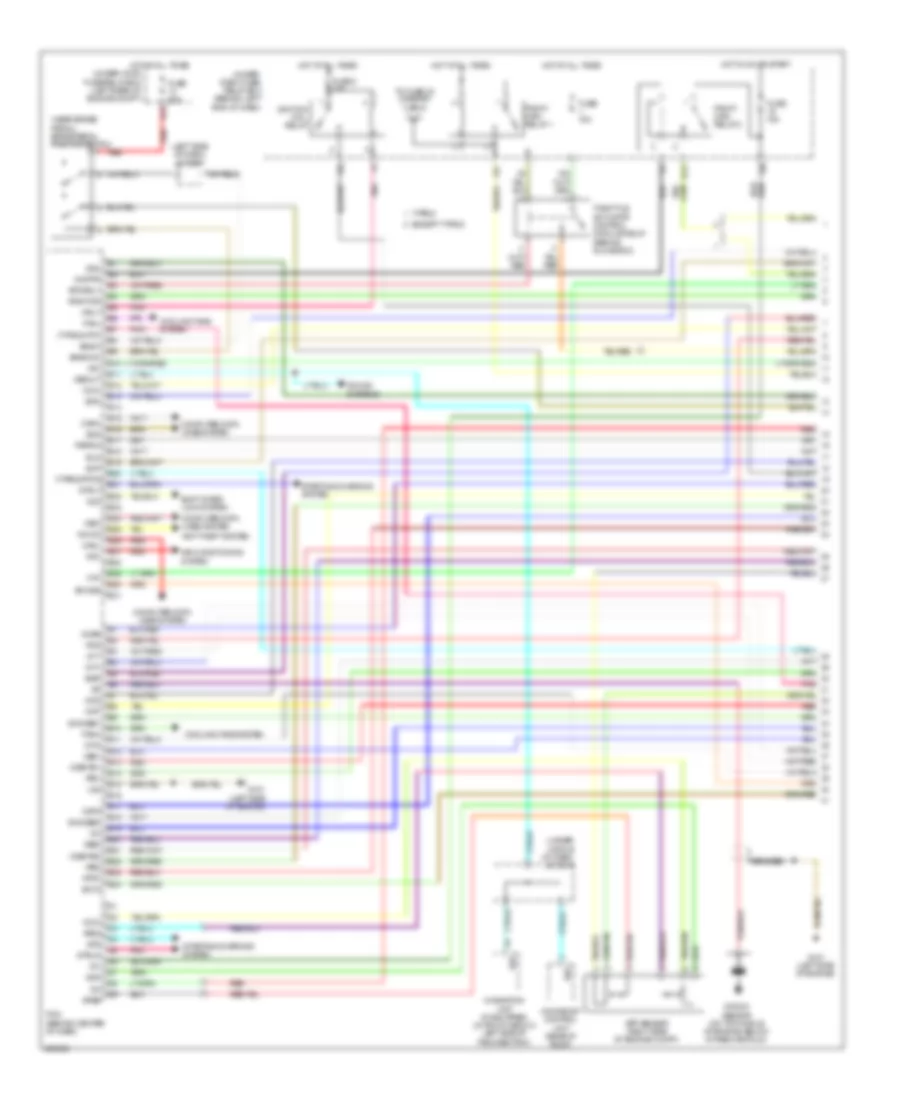
3.5L, Engine Performance Wiring Diagram, A/T (1 of 5) for Acura TL 2007
List of elements for 3.5L, Engine Performance Wiring Diagram, A/T (1 of 5) for Acura TL 2007:
- (left side of dash) j/c c507
- (near brake pedal) brake pedal position switch
- (type s)
- (under middle of dash) j/c c512
- Acc
- Afshtcr
- Air conditioning system
- Anti-theft system
- App sensor (right side of engine compt)
- Apsa
- Apsb
- Atpn
- B10
- B11
- B12
- B13
- B14
- B15
- B16
- B17
- B18
- B19
- B20
- B21
- B22
- B23
- B24
- Bksw
- Bkswnc
- Braided
- Canh
- Canl
- Ckpa
- Ckpb
- Cmp
- Computer data lines system
- Cooling fans system
- E10
- E11
- E12
- E13
- E14
- E15
- E16
- E17
- E18
- E19
- E20
- E21
- E22
- E23
- E24
- E25
- E26
- E27
- E28
- E29
- E30
- E31
- Ect2
- Egr
- Eld
- Etcsrly
- Except type s
- Fanh
- Fanl
- Fpc
- Fpcd
- Ftp
- Fuse 15a
- Fuse 2 15a
- Fuse 20a
- G101 (left side of engine)
- Hot at all times
- Hot in on or start
- Ig1
- Ignition coil relay
- Imocd
- Imofpr
- Imt+
- Imt-
- Imtm
- Ipb1
- Ipb2
- Knock sensor (on top middle of engine, below intake manifold)
- Lg2
- Mcs
- Moonroof control unit (rear of roof)
- Mrly
- Navigation unit (if equipped) (in trunk, below left side of package tray)
- Pcm (behind center of dash)
- Pcs
- Pgm-fi main relay 1
- Pgm-fi main relay 2
- Pnk
- Pspsw
- Red
- Scs
- Sdn
- Sg3
- Sg4
- Shift inter- lock system
- Sho2sb1
- Sho2sb2
- Sls
- Smode
- Sound systems
- Starting/charging system
- Strld
- Strly
- Sts
- Sup
- Throttle actuator control module relay (behind glove box)
- To fuse 23 (diagram 3 of 5)
- Type s
- Under- dash fuse/ relay box (behind left end of dash)
- Under-hood fuse/relay box (left rear of engine compt)
- Vcc3
- Vcc4
- Vcentb1
- Vcentb2
- Vsb1
- Vsb2
- Vsp
- Vssout
- Vsv
- Wen
- X23
- X31
- X32
- X38
3.5L, Engine Performance Wiring Diagram, A/T (2 of 5) for Acura TL 2007
List of elements for 3.5L, Engine Performance Wiring Diagram, A/T (2 of 5) for Acura TL 2007:
- (at left side of engine compt, near strut tower) evap canister purge valve
- (left rear of engine) engine mount control solenoid valve
- (left side of dash) j/c c508
- (left side of engine)
- (left side of engine) j/c c105
- (middle front of trunk) fuel tank unit
- (right side of engine) psp switch
- (under left rear of vehicle) fuel tank pressure (ftp) sensor
- Atf temperature sensor
- E16
- Ect sensor 2 (under front of engine compt)
- Except type s
- Fuel gauge sending unit
- Fuel pump
- G101 (left side of engine)
- G302 (behind left side of front bumper)
- G503 (under middle of dash)
- G603 (middle front of trunk)
- Imt actuator (right side of engine)
- Instrument cluster system
- J/c c105
- J/c c105 (left side of engine)
- J/c c106 (middle of engine)
- Map sensor (left side of engine)
- Output shaft (countershaft) speed sensor (in transmission housing)
- Pg2
- Pnk
- Red
- Sedf
- Sefd
- Sequential sportshift a/t shift switch
- Sequential sportshift mode switch
- Throttle actuator control module (behind glove box)
- Tp sensor/ throttle actuator (on throttle body)
- Tpsa
- Tpsb
- Transmission gear selection switch/ park pin switch/ a/t gear position indicator panel light (under center console)
- Type s
- Under-dash fuse/relay box (behind left end of dash) x5
- Vcc
3.5L, Engine Performance Wiring Diagram, A/T (3 of 5) for Acura TL 2007
List of elements for 3.5L, Engine Performance Wiring Diagram, A/T (3 of 5) for Acura TL 2007:
- (b1, s1) connector
- (left front of engine) front a/f sensor (b2, s1) connector
- (left rear of engine compt) under-hood fuse/relay box
- (left side of engine) egr valve & egr valve position sensor
- (under left rear of vehicle) evap canister vent shut valve
- A/f sensor relay
- Braided
- Chip resistor
- D13
- Eld unit
- Fp+
- Fp-
- Fpc
- Fpcd
- From pgm fi main relay 1 (diagram 1 of 5)
- Front a/f sensor (b2, s1)
- Front secondary ho2s sensor (b2, s2) (left front of engine)
- Fuel pump control module (type s) (left side of trunk)
- Fuse 15a
- Fuse 4 15a
- Fuse 7.5a
- G101 (left side of engine)
- G302 (behind left side of front bumper)
- G603 (middle front of trunk)
- Gnd
- Hot at all times
- Hot in on or start
- Ig1
- J/c c104 (middle of engine)
- J/c c105 (left side of engine)
- J/c c507 (left side of dash)
- N29
- Pnk
- Power distribution system
- Rear a/f sensor (b1, s1)
- Rear secondary ho2s sensor (b1, s2) (left rear of engine)
- Red
- S1 (thermal joint)
- S3 (thermal joint) (left side of engine)
- Under-dash fuse/relay box (behind left end of dash)
- X10
- X36
3.5L, Engine Performance Wiring Diagram, A/T (4 of 5) for Acura TL 2007
List of elements for 3.5L, Engine Performance Wiring Diagram, A/T (4 of 5) for Acura TL 2007:
- (left side of engine)
- (left side of engine) g101
- (on transaxle) transmission range switch
- A/t clutch pressure control solenoid valves (on transmission housing)
- A/t gear ind/cruise control dimming circuit
- A/t gear position detection circuit
- A/t gear position ind drive circuit
- A/t gear position indicator brightness control & dimming circuit
- A11
- A13
- A14
- B10
- B18
- Computer data lines system
- Cpu/fail safe circuit/can controller
- Drive circuit
- Fast controller area network transceiver
- Fuse 7.5a
- G101
- G102 (on right front of engine)
- G501 (under left side of dash)
- Gauge control module
- Hot in on or start
- Icm
- Ignition coils (middle of engine)
- Ignition coils (rear of engine)
- Input shaft (mainshaft) speed sensor (in transmission housing)
- J/c c104 (middle of engine)
- J/c c506 (left side of dash)
- J/c c508 (left side of dash)
- Lcd back light
- Micu
- Mil ind
- P16
- P20
- Red
- S1 (thermal joint)
- S2 (thermal joint)
- Shift ind
- Starting/ charging system
- Under- dash fuse/ relay box (behind left end of dash)
- Warning drive circuit
- X20
- X34
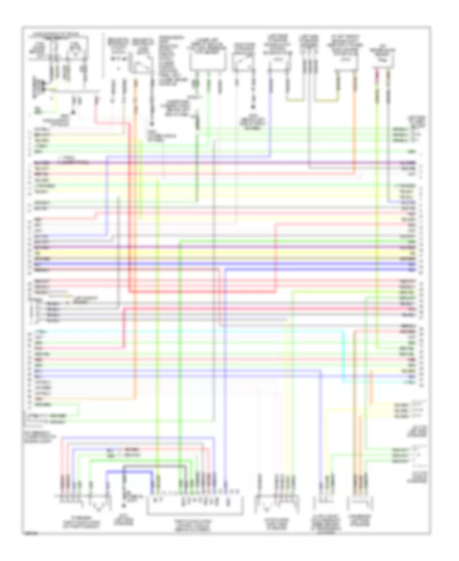
3.5L, Engine Performance Wiring Diagram, A/T (5 of 5) for Acura TL 2007
List of elements for 3.5L, Engine Performance Wiring Diagram, A/T (5 of 5) for Acura TL 2007:
- (behind crankshaft pulley) ckp sensors
- (middle of engine) fuel injectors
- (middle of engine) j/c c104
- (on transmission) 2nd clutch transmission fluid pressure switch
- (right side of engine) cmp sensor
- (thermal joint) s2
- 3rd clutch transmission fluid pressure switch (on transmission)
- 4th clutch transmission fluid pressure switch (on transmission)
- A10
- A11
- A12
- A13
- A14
- A15
- A16
- A17
- A18
- A19
- A20
- A21
- A22
- A23
- A24
- A25
- A26
- A27
- A28
- A29
- A30
- A31
- Afshtcb1
- Afshtcb2
- Altc
- Altf
- Altl
- Atft
- Atpd
- Atpfwd
- Atpl
- Atpp
- Atpr
- Atprvs
- B15
- Barometer sensor
- C10
- C11
- C12
- C13
- C14
- C15
- C16
- C17
- C18
- C19
- C20
- C21
- C22
- Cable reel (b: on steering column) (c: on steering wheel)
- Cruise control system
- D10
- D11
- D12
- D13
- D14
- D15
- D16
- D17
- Ect 1
- Ect sensor 1 (left side of engine)
- Egrp
- Engine) g101
- Except type s
- G101 (left side of engine)
- G501 (under left side of dash)
- Iat
- Iat sensor (left side of engine)
- Igp
- Igpls1
- Igpls2
- Igpls3
- Igpls4
- Igpls5
- Igpls6
- Inj1
- Inj2
- Inj3
- Inj4
- Inj5
- Inj6
- J/c c105 (left side of engine)
- J/c c106 (middle of engine)
- Lg1
- Lsa
- Lsb
- Lsc
- Map
- Op2sw
- Op3sw
- Op4sw
- Pcm (behind center of dash)
- Pg1
- Pg2
- Ppin
- Red
- Rocker arm oil control solenoid (right side of engine)
- Rocker arm oil pressure switch (right side of engine)
- Sdnp
- Sedf
- Sefd
- Sg1
- Sg2
- Sha
- Shb
- Shc
- Shd
- Shift control solenoid valves
- Shift interlock system
- So2shtcb1
- So2shtcb2
- Starting/ charging system
- Steering wheel (type s)
- Steering wheel downshift (-) switch
- Steering wheel upshift (+) switch
- Supp
- Type s
- Vbsol
- Vbsol2
- Vcc1
- Vcc2
- Vlblb1
- Vlblb2
- Vtpsw
- Vts
3.5L, Engine Performance Wiring Diagram, M/T (1 of 5) for Acura TL 2007
List of elements for 3.5L, Engine Performance Wiring Diagram, M/T (1 of 5) for Acura TL 2007:
- (behind left side of front bumper) g302
- A/f sensor relay
- Acc
- Active noise control unit (type s) (under middle
- Afshtcr
- Air conditioning system
- Anti-theft system
- Bksw
- Bkswnc
- Brake pedal position switch (near brake pedal)
- Can-h
- Can-l
- Clutch pedal position switch (near clutch pedal)
- Computer data lines system
- Cooling fans system
- Crmcls
- D13
- E10
- E11
- E12
- E13
- E14
- E15
- E16
- E17
- E18
- E19
- E20
- E21
- E22
- E23
- E24
- E25
- E26
- E27
- E28
- E29
- E30
- E31
- Ecm (behind center of dash)
- Eld
- Etcsrly
- Except type s
- Fan-l
- Fp+
- Fp-
- Fpc
- Fpcd
- Ftp
- Fuel pump
- Fuel pump control module (type s) (left side of trunk)
- Fuel tank pressure (ftp) sensor (under left rear of vehicle)
- Fuel tank unit (middle front of trunk)
- Fuse 15a
- Fuse 20a
- Fuse 7.5a
- G503 (under middle of dash)
- G603 (middle front of turnk)
- Gnd
- Hot at all times
- Hot in on or start
- Ig1
- Ignition coil relay
- Imocd
- Imofpr
- J/c c507 (left side of engine)
- Mrly
- N29
- Nep
- Of dash)
- Pgm-fi main relay 1
- Pgm-fi main relay 2
- Pnk
- Psp switch (right side of engine)
- Pspsw
- Red
- Rvs
- Scs
- Sg4
- Shift interlock system
- Type s
- Under-dash fuse/relay box (behind left end of dash)
- Under-hood fuse/relay box (left rear of engine compt)
- Vcc4
- Vssout
- Vsv
- Wen
- X10
- X31
- X32
- X36
- X38
3.5L, Engine Performance Wiring Diagram, M/T (2 of 5) for Acura TL 2007
List of elements for 3.5L, Engine Performance Wiring Diagram, M/T (2 of 5) for Acura TL 2007:
- (left side of dash) j/c c508
- (under left rear of vehicle) evap canister vent shut valve
- Apsa
- Apsb
- Audio unit
- B10
- B11
- B12
- B13
- B14
- B15
- B16
- B17
- B18
- B19
- B20
- B21
- B22
- B23
- B24
- Barometer sensor
- C26
- Ckpa
- Ckpb
- Cmp
- Cooling fans system
- D10
- D11
- D12
- D13
- D14
- D15
- D16
- D17
- Ecm (behind center of dash)
- Ect2
- Egr
- Eld unit
- Fan-h
- Fuse 15a
- G302 (behind left side of front bumper)
- Hot at all times
- Ig1
- Imt+
- Imt-
- Imtm
- Ipb1
- Ipb2
- J/c c512 (under middle of dash)
- Lg2
- Mcs
- Moonroof control unit (rear of roof)
- Navigation unit (if equipped) (in trunk, below left side of package tray)
- Pcs
- Red
- Sg3
- Sho2sb1
- Sho2sb2
- Starting/ charging system
- Sts
- System charging starting/
- Throttle actuator control module relay (behind glove box)
- Under-dash fuse/relay box (behind left end of dash)
- Under-hood fuse/relay box (left rear of engine compt)
- Vbsol2
- Vcc3
- Vcentb1
- Vcentb2
- Vlblb1
- Vlblb2
- Vsb1
- Vsb2
- X23
3.5L, Engine Performance Wiring Diagram, M/T (3 of 5) for Acura TL 2007
List of elements for 3.5L, Engine Performance Wiring Diagram, M/T (3 of 5) for Acura TL 2007:
- (at left side of engine compt, near strut tower) evap canister purge valve
- (left rear of engine) engine mount control solenoid valve
- (left side of engine) g101
- (left side of engine) j/c c105
- (middle front of trunk) (except type s) fuel tank unit
- (on top middle of engine, below intake manifold) knock sensor
- Braided
- Chip resistor
- Ect sensor 2 (under front of engine compt)
- Front a/f sensor (bank 2, sensor 1)
- Front secondary ho2s sensor (bank 2, sensor 2) (left front of engine)
- Fuel pump
- G101 (left side of engine)
- G603 (middle front of trunk)
- J/c c106 (middle of engine)
- Rear a/f sensor (bank 1, sensor 1)
- Rear secondary ho2s sensor (bank 1, sensor 2) (left rear of engine)
- Red
3.5L, Engine Performance Wiring Diagram, M/T (4 of 5) for Acura TL 2007
List of elements for 3.5L, Engine Performance Wiring Diagram, M/T (4 of 5) for Acura TL 2007:
- (in transmission housing) input shaft (mainshaft) speed sensor
- (left side of engine) g101
- (right side of engine compt) app sensor
- (right side of engine) imt actuator
- A13
- A14
- B10
- B18
- Ckp sensors (behind crankshaft pulley)
- Cmp sensor (right side of engine)
- Computer data lines system
- Cpu/ fail safe circuit/ can controller
- Fast controller area network transceiver
- Fuse 7.5a
- G101 (left side of engine)
- G501 (under left side of dash)
- Gauge control module
- Hot in on or start
- Icm
- Ignition coils (middle of engine)
- Ignition coils (rear of engine)
- J/c c104 (middle of engine)
- J/c c105 (left side of engine)
- J/c c106 (middle of engine)
- J/c c506 (left side of dash)
- J/c c508 (left side of dash)
- Mil ind
- Red
- S1 (thermal joint)
- Under-dash fuse/relay box (behind left end of dash)
- Warning drive circuit
- X20
- X34
3.5L, Engine Performance Wiring Diagram, M/T (5 of 5) for Acura TL 2007
List of elements for 3.5L, Engine Performance Wiring Diagram, M/T (5 of 5) for Acura TL 2007:
- (behind glove box) throttle actuator control module
- (in transmission housing) output shaft (countershaft) speed sensor
- (left side of engine) egr valve & egr valve position sensor
- (left side of engine) g101
- (left side of engine) j/c c105
- (left side of engine) map sensor
- (middle of engine) j/c c104
- (on throttle body) tp sensor/ throttle actuator
- A10
- A11
- A12
- A13
- A14
- A15
- A16
- A17
- A18
- A19
- A20
- A21
- A22
- A23
- A24
- A25
- A26
- A27
- A28
- A29
- A30
- A31
- Afshtcb1
- Afshtcb2
- Altc
- Altf
- Altl
- C10
- C11
- C12
- C13
- C14
- C15
- C16
- C17
- C18
- C19
- C20
- C21
- C22
- Ecm (behind center of dash)
- Ect sensor 1 (left side of engine)
- Ect1
- Egrp
- Except type s
- Fuel injectors (middle of engine)
- G101 (left side of engine)
- Gnd
- Iat
- Iat sensor (left side of engine)
- Igp
- Igpls1
- Igpls2
- Igpls3
- Igpls4
- Igpls5
- Igpls6
- Inj1
- Inj2
- Inj3
- Inj4
- Inj5
- Inj6
- J/c c104 (middle of engine)
- J/c c105 (left side of engine)
- Lg1
- Map
- Pg1
- Pg2
- Red
- Rocker arm oil control solenoid (right side of engine)
- Rocker arm oil pressure switch (right side of engine)
- S1 (thermal joint)
- S3 (thermal joint) (left side of engine)
- Sedf
- Sefd
- Sg1
- Sg2
- So2shtcb1
- So2shtcb2
- Starting/ charging system
- Starting/charging system
- Tpsa
- Tpsb
- Type s
- Vbsol
- Vcc
- Vcc1
- Vcc2
- Vtpsw
- Vts

 Čeština
 Dansk
Dansk Deutsch
 Ελληνικά
 English
 English
 Español
 Français
 Français
 עברית
עברית Hrvatski
 Magyar
 Italiano
 日本語
日本語 한국어
한국어 Nederlands
 Polski
 Português
 Português
 Română
 Русский
 Slovenčina
 Slovenščina
 Svenska
 Türkçe
 中文 (中国)