SUPPLEMENTAL RESTRAINTS
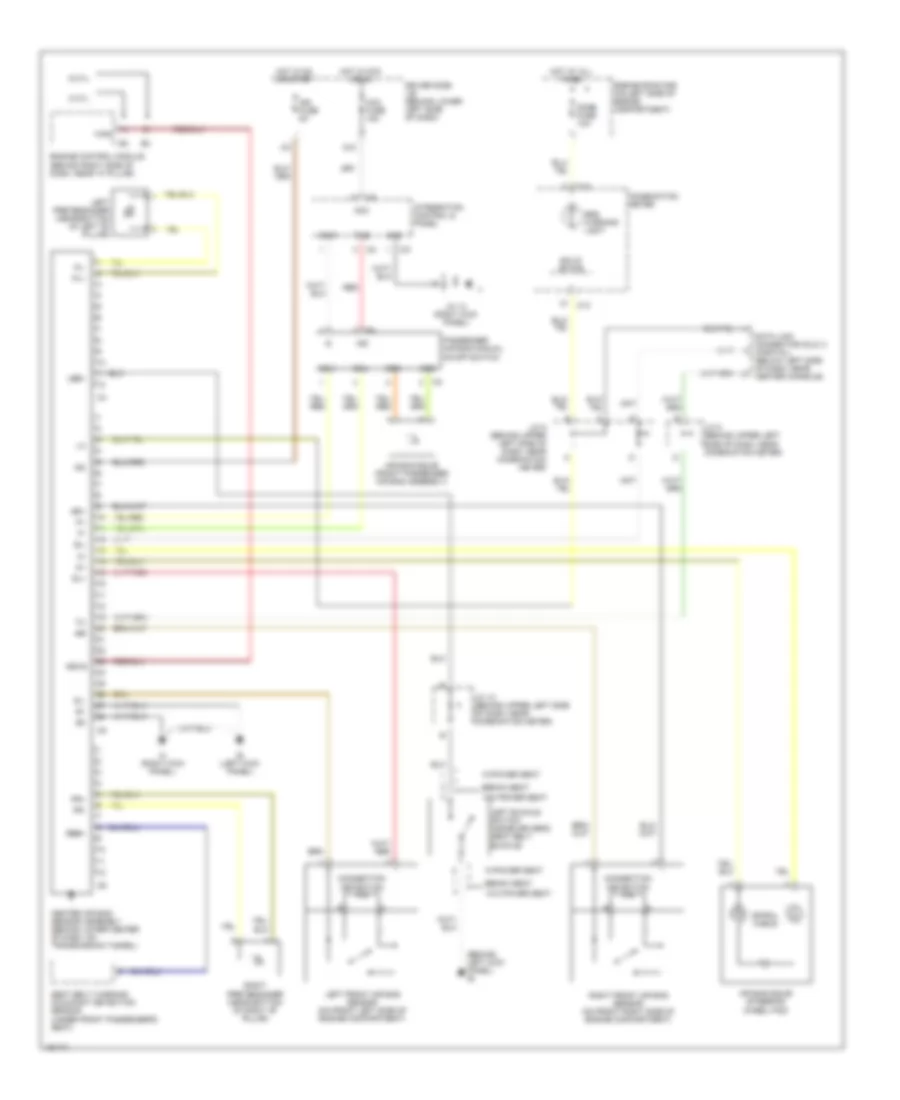
Supplemental Restraints Wiring Diagram for Toyota Tundra Limited 2003
List of elements for Supplemental Restraints Wiring Diagram for Toyota Tundra Limited 2003:
- (behind left kick panel) ie
- 6 cyl
- 8 cyl
- Acc
- Acc fuse 15a
- Air bag squib (front passenger air bag assembly)
- Air bag squib (steering wheel pad)
- Bench seat
- C12
- C13
- Center air bag sensor assembly (behind lower center of dash, on transmission tunnel)
- Combination meter
- Connection detection pin
- Data link connector (dlc) 3 (partial) (below left side of dash, near center console)
- Dome fuse 10a
- Driver side j/b (behind lower left side of dash)
- Ecu+
- Ecu-
- Engine control module (behind right side of dash, near "a" pillar)
- Engine room r/b (on left side of engine compartment)
- F/ps
- G10
- Gnd
- Gnd1
- Gsw2
- Hot at all times
- Hot in acc or on
- Hot in on or start
- I24
- I25
- Ie (left kick panel)
- Ig2
- Ign fuse 5a
- Ih (right kick panel)
- Ind
- Integration control & panel
- J/c 10 (behind upper left side of dash, near combination meter)
- J/c 13 (right kick panel)
- J/c 5 (behind upper left side of dash, near combination meter)
- J/c 8 (behind upper left side of dash, near combination meter)
- Lbe+
- Left buckle switch inside driver's seat belt buckle)
- Left front air bag sensor (on front left side of engine compartment)
- Left pretensioner (near bottom of left "b" pillar)
- Passenger air bag manual on-off switch
- Pind
- Pl+
- Pl-
- Pr+
- Pr-
- Rbe+
- Red
- Right front air bag sensor (on front right side of engine compartment)
- Right pretensioner (near bottom of right "b" pillar)
- Seat belt warning occupant detection sensor (under front passenger's seat)
- Sil
- Sl+
- Sl-
- Solid state
- Spiral cable
- Sqb+
- Sqb-
- Sr+
- Sr-
- Srs warning light
- W/o power seat
- W/power seat
 Čeština
 Dansk
Dansk Deutsch
 Ελληνικά
 English
 English
 Español
 Français
 Français
 עברית
עברית Hrvatski
 Magyar
 Italiano
 日本語
日本語 한국어
한국어 Nederlands
 Polski
 Português
 Português
 Română
 Русский
 Slovenčina
 Slovenščina
 Svenska
 Türkçe
 中文 (中国)
 Suomi
Suomi