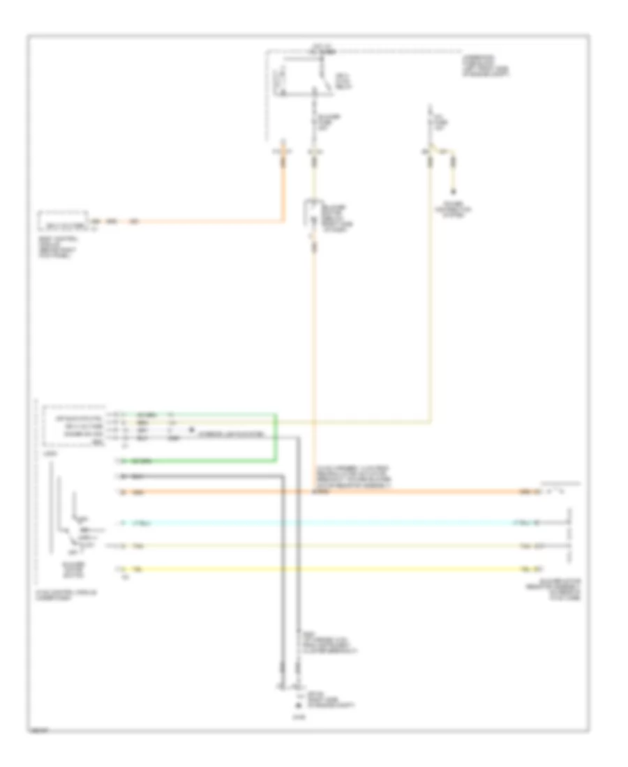
AIR CONDITIONING
Compressor Wiring Diagram for GMC Canyon 2007
 https://portal-diagnostov.com/license.html
Automotive Electricians Portal FZCO
Automotive Electricians Portal FZCO
https://portal-diagnostov.com/license.html
https://portal-diagnostov.com/license.html
Automotive Electricians Portal FZCO
Automotive Electricians Portal FZCO
List of elements for Compressor Wiring Diagram for GMC Canyon 2007:
- 5v ref
- A/c comp fuse 10a
- A/c comp relay
- A/c compressor clutch (left front of engine)
- A/c refrigerant pressure sensor (right rear of engine compt)
- A/c req sig
- A42
- A43
- A47
- Body control module (behind right kick panel)
- C7 f5
- Computer data lines system
- Evaporator temperature sensor (lower right side of dash)
- F11
- G103 (lower left side of engine)
- G106
- Hot at all times
- Hot in run or start
- Hvac control module (under dash)
- Ign fuse 15a
- Logic
- Low ref
- Powertrain control module (pcm) (right rear corner of engine compt)
- Press sens sig
- Rly ctrl
- S200 (hvac harness, 6 cm from instrument cluster breakout)
- Sensor module
- Serial data
- Sp106 (right side of engine compt)
- Underhood fuse block (left front side of engine compt)
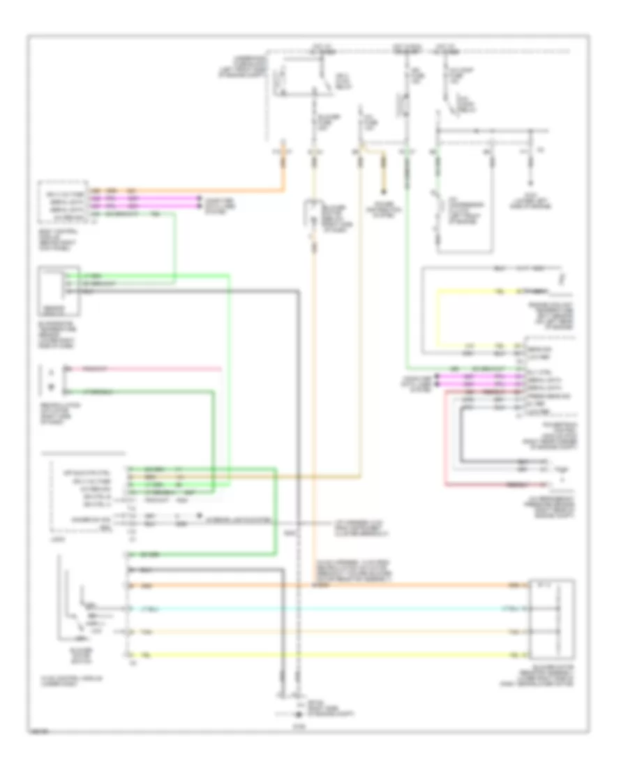
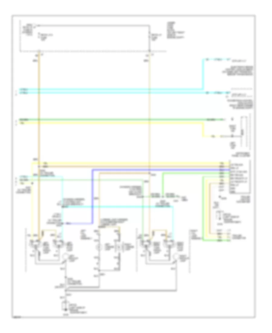
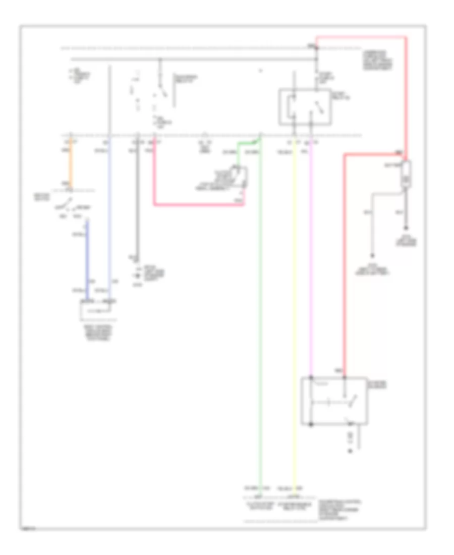
Heater Wiring Diagram for GMC Canyon 2007
List of elements for Heater Wiring Diagram for GMC Canyon 2007:
- (hvac harness, 14 cm from recirculation actuator breakout toward blower motor resistor assembly) s202
- A/c fuse 10a
- A26
- B c4
- Blower fuse 30a
- Blower motor (below right side of dash)
- Blower motor resistor assembly (on rear of hvac case)
- Blower motor switch
- Body control module (behind right kick panel)
- Dimmer sw sig
- F10 c7
- G106
- Gnd
- High
- Hot at all times
- Hvac control module (under dash)
- Ign 3 hvac relay
- Ign 3 voltage
- Interior lights system
- Logic
- Low
- Off
- Off blr mtr ctrl
- Power distribution system
- S200 (i/p harnss, 6 cm from instrument cluster breakout)
- Sp106 (right side of engine compt)
- Tan
- Underhood fuse block (left front side of engine compt)
Manual A/C Wiring Diagram for GMC Canyon 2007
List of elements for Manual A/C Wiring Diagram for GMC Canyon 2007:
- (hvac harness, 14 cm from recirculation actuator breakout toward blower motor resistor assembly) s202
- (i/p harness, 6 cm from instrument cluster breakout)
- 5v ref
- A/c comp fuse 10a
- A/c comp relay
- A/c compressor clutch (left front of engine)
- A/c fuse 10a
- A/c refrigerant pressure sensor (right rear of engine compt)
- A/c req sig
- A26
- A42
- A43
- A47
- B c4
- Blower fuse 30a
- Blower motor (below right side of dash)
- Blower motor resistor assembly (lower right side of dash, near blower motor)
- Blower motor switch
- Body control module (behind right kick panel)
- C7 f5
- Computer data lines system
- Dimmer sw sig
- Dr ctrl a
- Dr ctrl b
- Engine coolant temperature (ect) sensor (on left rear of engine)
- Evaporator temperature sensor (lower right side of dash)
- F10 c7
- F11
- G103 (lower left side of engine)
- G106
- Gnd
- High
- Hot at all times
- Hot in run or start
- Hvac control module (under dash)
- Ign 3 hvac relay
- Ign 3 voltage
- Ign fuse 15a
- Interior lights system
- Logic
- Low
- Low ref
- Nca
- Off
- Off blr mtr ctrl
- Power distribution system
- Powertrain control module (pcm) (right rear corner of engine compt)
- Press sens sig
- Recirculation actuator (right side of dash)
- Rly ctrl
- S200
- Sens sig
- Sensor module
- Serial data
- Sp106 (right side of engine compt)
- Tan
- Underhood fuse block (left front side of engine compt)
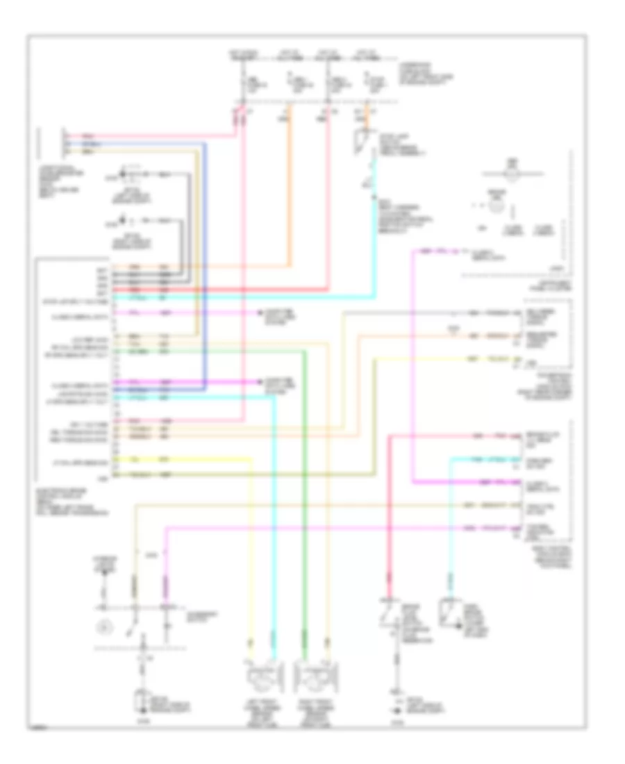
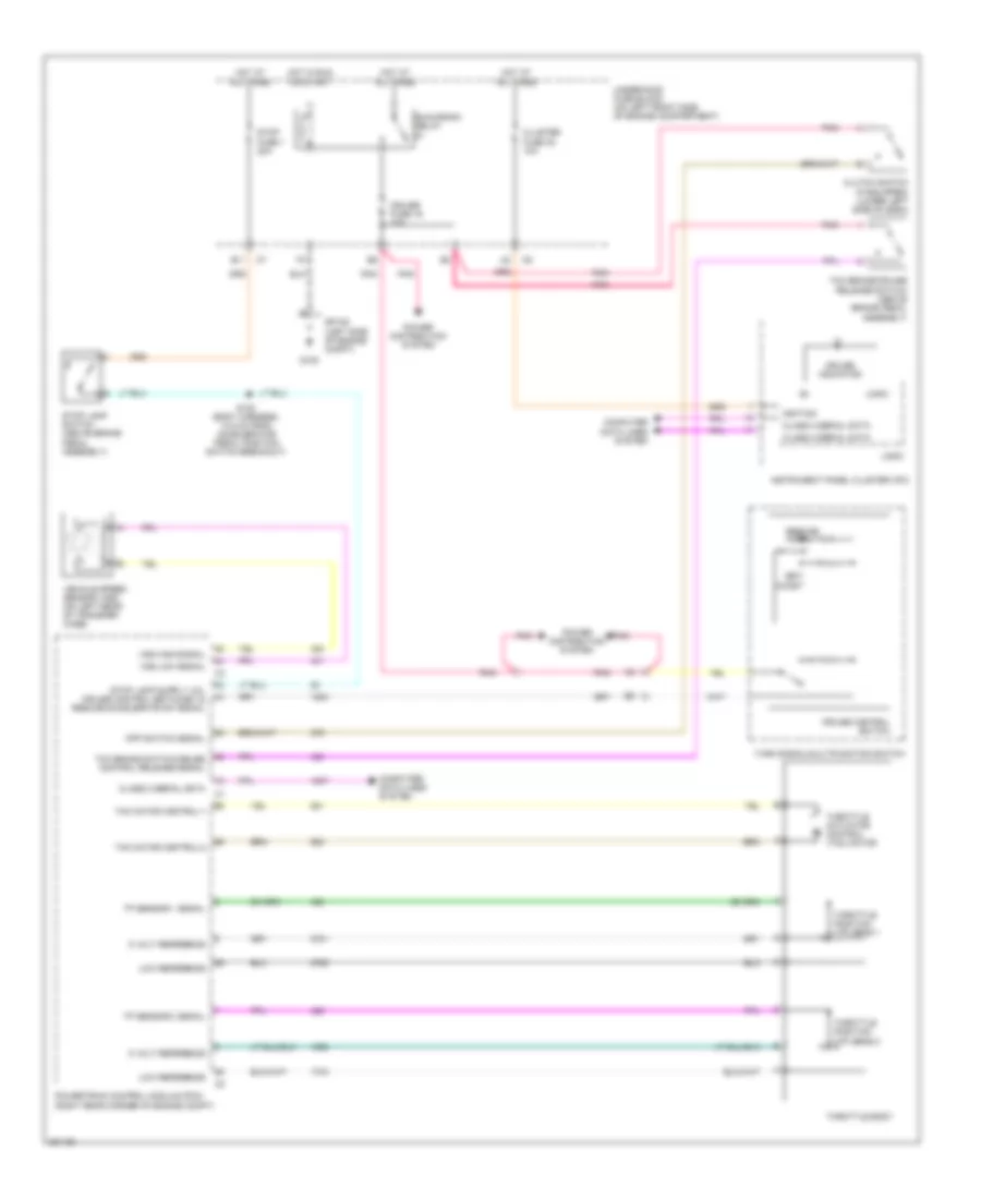
ANTI-LOCK BRAKES
Anti-lock Brakes Wiring Diagram for GMC Canyon 2007
List of elements for Anti-lock Brakes Wiring Diagram for GMC Canyon 2007:
- 2wd
- A17
- A26
- A31
- A39
- A45
- Abs 1 fuse 45 30a
- Abs 2 fuse 44 40a
- Abs fuse 16 10a
- Abs ind
- Accessory switch
- B c5
- Bat
- Body control module (bcm) (behind right kick panel)
- Brake fluid level switch (on brake fluid reservoir)
- Brake fluid lvl sens sig
- Brake ind
- C2 b
- C2 h
- Class 2 (ebcm)
- Class 2 serial data
- Computer data lines system
- Del torque sig (2wd)
- Delivered torque signal
- E11 c7
- Electronic brake control module (ebcm) (on inner left frame rail, beside transmission)
- G105
- G106
- Gnd
- Hot at all times
- Hot in run or start
- Ign
- Ign 1 voltage
- Instrument panel cluster
- Interior lights system
- Left front wheel speed sensor (on left front hub)
- Lf spd sens sply volt
- Lf whl spd sens sig
- Lng rate sig (4wd)
- Logic
- Longitudinal accelerometer sensor (4wd) (below driver seat)
- Low ref (4wd
- Park brake switch (lower left end of dash)
- Park brk sw sig
- Pnk
- Powertrain control module (pcm) (right rear corner of engine compt)
- Red
- Req torque sig (2wd)
- Requested torque signal
- Rf spd sens sply volt
- Rf whl spd sens sig
- Right front wheel speed sensor (on right front hub)
- S100 (body harness, 14.5 cm from accelerator pedal position switch breakout)
- Sp105 (left side of engine compt)
- Sp106 (right side of engine compt)
- Stop fuse 1 20a
- Stop lamp switch (above brake pedal assembly)
- Stop lmp sply voltage
- Tan
- Tcs req indicator ctrl
- Trac ctrl sw sig
- Underhood fuse block (on left front side of engine compt)
- Vss
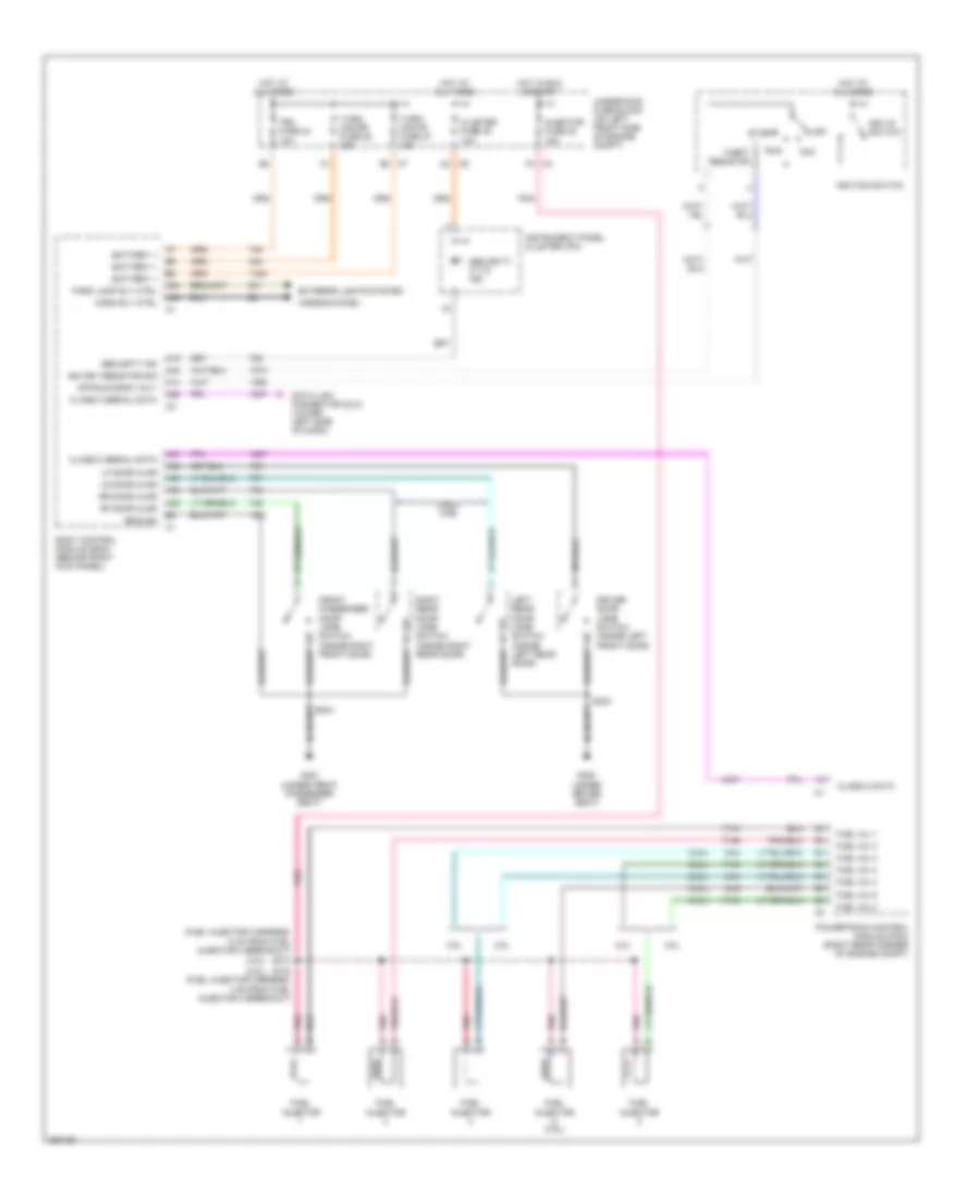
ANTI-THEFT
Anti-theft Wiring Diagram for GMC Canyon 2007
List of elements for Anti-theft Wiring Diagram for GMC Canyon 2007:
- (2.8l)
- (3.5l)
- (fuel injector harness, 5 cm from fuel injector 4 breakout)
- 2.8l
- 3.5l
- A14
- A19
- A2 c6
- A24
- A32
- A38
- A39
- A40
- A42
- A44
- A47
- Acc
- B3 c7
- Battery +
- Body control module (bcm) (behind right kick panel)
- C2 f4
- Class 2 data
- Class 2 serial data
- Cluster fuse 38 10a
- Crew cab
- Data link connector (dlc) (lower left side of dash)
- Driver door jamb switch (inside left front door)
- Exterior lights system
- Front passenger door jamb switch (inside right front door)
- Fuel inj 1
- Fuel inj 2
- Fuel inj 3
- Fuel inj 4
- Fuel inj 5
- Fuel injector
- Fuel injector (3.5l)
- G300 (under driver seat)
- G301 (under front passenger seat)
- Ground
- Horn rly ctrl
- Horns system
- Hot at all times
- Hot in run & start
- Ign key resistor sig
- Ignition switch
- Injector fuse 22 15a
- Instrument panel cluster (ipc)
- Key-in switch
- Left rear door jamb switch (inside left rear door)
- Lf door ajar
- Lr door ajar
- Off
- Off/run/crnk volt
- Park lamp rly ctrl
- Pnk
- Powertrain control module (pcm) (right rear corner of engine compt)
- Rf door ajar
- Right rear door jamb switch (inside right rear door)
- Rr door ajar
- Run
- S103
- S104 (fuel injector harness, 4 cm from fuel injector 4 breakout)
- S303
- Security ind
- Security/ c.t.d. ind
- Start
- Tbc fuse 34 10a
- Theft resistor
- Turn/ haz fr fuse 37 15a
- Turn/ haz rr fuse 28 15a
- Underhood fuse block (on left front side of engine compt)
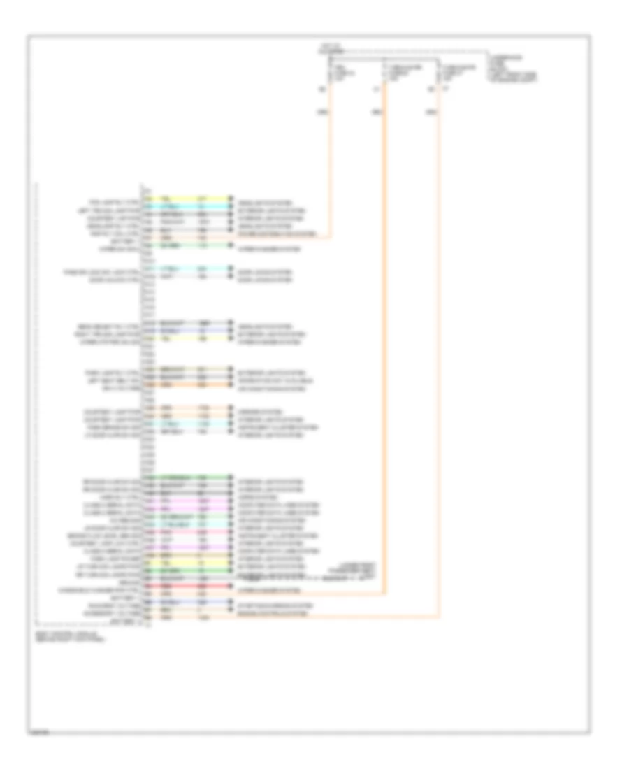
BODY CONTROL MODULES
Body Control Modules Wiring Diagram (1 of 2) for GMC Canyon 2007
List of elements for Body Control Modules Wiring Diagram (1 of 2) for GMC Canyon 2007:
- (under front passenger seat) g301
- A/c req sig
- A10
- A11
- A12
- A13
- A14
- A15
- A16
- A17
- A18
- A19
- A20
- A21
- A22
- A23
- A24
- A25
- A26
- A27
- A28
- A29
- A30
- A31
- A32
- A33
- A34
- A35
- A36
- A37
- A38
- A39
- A40
- A41
- A42
- A43
- A44
- A45
- A46
- A47
- A48
- Accessory voltage
- Air conditioning system
- Battery +
- Beam select rly ctrl
- Body control module (behind right kick panel)
- Brake fluid level sen sig
- Class 2 serial data
- Computer data lines system
- Courtesy lamp low ctrl
- Courtesy lamp pwr
- Courtesy lmp pwr
- Door locks system
- Door unlock ctrl
- Engine controls system
- Exterior lights system
- Fog lamp rly ctrl
- Ground
- Headlamp rly ctrl
- Headlights system
- Horn rly ctrl
- Horns system
- Hot at all times
- Ign 3 voltage
- Information not available
- Instrument cluster system
- Interior lights system
- Left seat belt sw
- Left trn sig lamp pwr
- Lf door ajar sw sig
- Lr door ajar sw sig
- Lr turn sig lamps pwr
- Mirrors system
- Park brake sw sig
- Park lamp power
- Park lamp rly ctrl
- Pass dr lock sw lock ctrl
- Pnk
- Power distribution system
- Rap rly coil ctrl
- Red
- Right trn sig lamp pwr
- Rr door ajar sw sig
- Rr turn sig lamps pwr
- Run/crnk voltage
- S304
- Starting/charging system
- Tbc fuse 34 10a
- Turn/haz fr fuse 37 15a
- Turn/haz rr fuse 28 15a
- Underhood fuse block (left front side of engine compt)
- Windshield washer pmp ctrl
- Wiper mtr prk sw sig
- Wiper sw sig 2
- Wiper/washer system
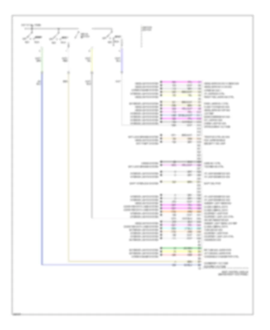
Body Control Modules Wiring Diagram (2 of 2) for GMC Canyon 2007
List of elements for Body Control Modules Wiring Diagram (2 of 2) for GMC Canyon 2007:
- A10
- A11
- A12
- A13
- A14
- A15
- A16
- A17
- A18
- A19
- A20
- A21
- A22
- A23
- A24
- A25
- A26
- A27
- A28
- A29
- A30
- A31
- A32
- A33
- A34
- A35
- A36
- A37
- A38
- A39
- A40
- A41
- A42
- A43
- A44
- A45
- A46
- A47
- A48
- Acc
- Accessory voltage
- Ambient light sens low ref
- Ambient light sens sig
- Anti-lock brakes system
- Anti-theft system
- Body control module (behind right kick panel)
- Cargo lamp sw sig
- Class 2 serial data
- Computer data lines system
- Courtesy lamp low ctrl
- Courtesy lamp pwr
- Dome override sw sig
- Exterior lights system
- Flash to pass sw sig
- Fog lamps enable
- Front fog lamps ind ctrl
- Hazard sw sig
- Headlamps dim sw hi beam sig
- Headlamps sw hi on sig
- Headlamps sw off sig
- Headlights system
- Horn rly ctrl
- Horns system
- Hot at all times
- I/p lamp dimmer sw sig
- I/p lamps dim ctrl
- Ign key resistor sig
- Ignition switch
- Int lamp sw sig
- Interior lights system
- Key-in switch
- Low ref
- Lr turn sig lamps pwr
- Off
- Off/run/crnk voltage
- Park lamps rly ctrl
- Red
- Rr turn sig lamps pwr
- Run
- Run/crnk voltage
- Security ind lamp
- Shift interlock system
- Shift sol pwr
- Start
- Tcs req ind ctrl
- Traction ctrl sw sig
- Turn sig sw sig
- Windshield washer pmp ctrl
- Wiper sw sig 1
- Wiper/washer system
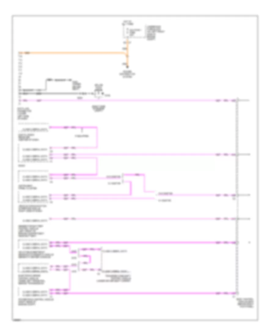
COMPUTER DATA LINES
Computer Data Lines Wiring Diagram for GMC Canyon 2007
List of elements for Computer Data Lines Wiring Diagram for GMC Canyon 2007:
- (right side of engine compt)
- 2wd
- 4wd
- A38
- A39
- A41
- A42
- A44
- A47
- Aux pwr 1 fuse 20a
- Body control module (bcm) (behind right kick panel)
- Class 2 serial data
- Data link connector (lower left side of dash)
- Digital radio receiver (center of dash)
- Electronic brake control module (inner left frame rail, beside transmission)
- G106
- G300 (under driver seat)
- Generator battery control module (left front of engine compartment, near battery)
- Hot at all times
- If equipped
- Inflatable restraint sensing & diagnostic module (beneath center console)
- Instrument panel cluster
- Power distribution system
- Powertrain control module (right rear of engine compt)
- Radio
- S200
- S201
- Splice pack sp106
- Transfer case shift control module (under driver seat carpet)
- Underhood fuse block (on left front side of engine compt)
- Vehicle communication interface module (right side of dash)
- W/ onstar
- W/o onstar
CRUISE CONTROL
Cruise Control Wiring Diagram for GMC Canyon 2007
List of elements for Cruise Control Wiring Diagram for GMC Canyon 2007:
- 5 volt reference
- Class 2 serial data
- Cluster fuse 38 10a
- Clutch switch (if equipped) (lower left side of dash)
- Coast
- Computer data lines system
- Cpp switch signal
- Cruise control switch
- Cruise fuse 19 10a
- Cruise indicator
- E11
- G105
- Hot at all times
- Hot in run or start
- Ignition
- Instrument panel cluster (ipc)
- Logic
- Low reference
- Pnk
- Power distribution system
- Powertrain control module (pcm) (right rear corner of engine compt)
- Resume/ accel
- Run/crank relay
- S100 (body harness, 14.5 cm from accelerator pedal position switch breakout)
- Set/
- Sp105 (left side of engine compt)
- Stop fuse 1 20a
- Stop lamp switch (above brake pedal assembly)
- Tac motor control-1
- Tac motor control-2
- Tcc brake switch/cruise control release signal
- Tcc brake/cruise release switch (above brake pedal assembly)
- Throttle actuator control (tac) motor
- Throttle body
- Throttle position (tp) sens 1
- Throttle position (tp) sens 2
- Tp sensor 1 signal
- Tp sensor 2 signal
- Turn signal/multifunction switch
- Underhood fuse block (on left front side of engine compartment)
- Vehicle speed sensor (vss) (on left rear of transfer case)
- Vss high signal
- Vss low signal
ENGINE PERFORMANCE
2.9L VIN 9
2.9L VIN 9, Engine Performance Wiring Diagram (1 of 5) for GMC Canyon 2007
List of elements for 2.9L VIN 9, Engine Performance Wiring Diagram (1 of 5) for GMC Canyon 2007:
- (body harness, 14.5 cm from accelerator pedal position switch breakout) s100
- (chassis harness, 39 cm before fuel pump & sender assembly)
- (part of transfer case) (4wd) transfer case shift control module
- 4wd lo sw
- A/c comp rly
- A/c press
- A/c refrigerant pressure sensor (right rear of engine compt)
- Accelerator pedal position (app) sensor (on accelerator bracket)
- Accy volt
- Air conditioning system
- App 1
- App 1 +5v ref
- App 1 low ref
- App 2
- App 2 +5v ref
- App 2 low ref
- App sens 1
- App sens 2
- Arp +5v ref
- Arp low ref
- Batt pos volt
- Can vent fuse 10a
- Class 2 data
- Cluster fuse 10a
- Computer data lines system
- Cpp sw sig
- Cruise control system
- Cruise ctrls
- Diag enable
- E11
- Evap vent sol
- Evaporative emission (evap) canister vent solenoid (on side of evap canister, above spare tire)
- Exterior lights system
- Ftp +5v ref
- Fuel lvl sens
- Fuel pump rly
- Fuel tank press
- Fuel tank pressure (ftp) sensor (at top left rear of fuel tank)
- Hot at all times
- Hot in run & start
- Ignition 1 volt
- Instrument panel cluster
- Iss sig
- Low ref
- Malfunction indicator lamp (mil)
- Mil ctrl
- Pcm 1 fuse 10a
- Pcm b fuse 10a
- Pnk
- Pnp/clutch sig
- Powertrain control module (pcm) (right rear corner of engine compt)
- S310
- Starter rly
- Starting/ charging system
- Stop fuse 20a
- Stop lamp
- Stop lamp switch (above brake pedal assembly)
- Tan
- Tcc brk sw
- Underhood fuse block (on left front side of engine compartment)
- Vehicle spd sig
2.9L VIN 9, Engine Performance Wiring Diagram (2 of 5) for GMC Canyon 2007
List of elements for 2.9L VIN 9, Engine Performance Wiring Diagram (2 of 5) for GMC Canyon 2007:
- (2wd)
- (on inner left frame rail, beside transmission) electronic brake control module (ebcm)
- Acc
- Accy volt
- Body control module (bcm) (behind right kick panel)
- Etc fuse 15a
- Fuel pmp fuse 15a
- Fuel pump & sender assembly (top of fuel tank)
- Fuel pump relay
- G105
- Heated oxygen sensor (ho2s) 1 (right side of engine, on exhaust manifold)
- Heated oxygen sensor (ho2s) 2 (in exhaust pipe, adjacent to transmission)
- Hot at all times
- Ignition switch
- Nca
- O2 sensor fuse 10a
- Off
- Pnk
- Powertrain relay
- Run
- S401
- Splice pack sp105 (left side of engine compt)
- Start
- Underhood fuse block (on left front side of engine compartment)
2.9L VIN 9, Engine Performance Wiring Diagram (3 of 5) for GMC Canyon 2007
List of elements for 2.9L VIN 9, Engine Performance Wiring Diagram (3 of 5) for GMC Canyon 2007:
- (2wd)
- 1-2 sol
- 2-3 sol
- 3-2 sol
- A/t fluid pressure manual valve position switch
- Automatic transaxle (if equpped)
- Del torque
- Engine oil pressure (eop) sensor (right front of engine)
- Evap purge
- Fluid temp sensor
- Ho2s 2 hi
- Ho2s 2 htr
- Ho2s 2 low
- Input speed sensor
- Iss low ref
- Low oil sw
- Low ref
- Oil press
- Park/neutral position (pnp) switch (lower left side of transmission)
- Pc sol
- Pnk
- Powertrain control module (pcm) (right rear corner of engine compt)
- Pressure control solenoid
- Red
- Req torque
- Rev
- S133
- Tan
- Tcc pwm sol
- Tcc sol
- Tfp sw a
- Tfp sw b
- Tfp sw c
- Tft sens
- Tr sw a
- Tr sw b
- Tr sw p
- Tr sw sig
- Vss sig hi
- Vss sig low
2.9L VIN 9, Engine Performance Wiring Diagram (4 of 5) for GMC Canyon 2007
List of elements for 2.9L VIN 9, Engine Performance Wiring Diagram (4 of 5) for GMC Canyon 2007:
- (2wd: on left rear of tranmission) (4wd: on left rear of transfer case) vehicle speed sensor (vss)
- B11
- C11
- Control
- D11
- E11
- Erls fuse 15a
- Evaporative emission (evap) canister purge solenoid (left side of engine, below intake)
- F11
- G102 (lower left side of engine)
- G103 (lower left side of engine)
- Ground
- Hot in run & start
- Iat
- Ign fuse 15a
- Ignition
- Ignition coils
- Injector fuse 15a
- Intake air temperature (iat)/ mass air flow (maf) sensor (in air intake duct, top right of engine)
- Maf
- Nca
- Plug
- Pnk
- Spark plug
- Tan
- Trans fuse 10a
- Underhood fuse block (on left front side of engine compartment)
2.9L VIN 9, Engine Performance Wiring Diagram (5 of 5) for GMC Canyon 2007
List of elements for 2.9L VIN 9, Engine Performance Wiring Diagram (5 of 5) for GMC Canyon 2007:
- (left rear of engine block, below starter) crankshaft position (ckp) sensor
- (lower left side of engine) g102
- (top left side of engine, on intake manifold) manifold absolute pressure (map) sensor
- (top right front of engine) camshaft position (cmp) sensor
- A11
- B11
- Camshaft position (cmp) actuator solenoid (on top right front of engine)
- Ckp low ref
- Ckp sig
- Cmp +12v ref
- Cmp low ref
- Cmp sig
- Cpa +5v ref
- Cpa low ref
- Ect low ref
- Ect sens
- Engine coolant temperature (ect) sensor (on left rear of engine)
- Fuel inj 1
- Fuel inj 2
- Fuel inj 3
- Fuel inj 4
- Fuel injectors (top of engine, attached to fuel rail)
- Gen field
- Gen reg cntrl
- Generator
- Generator battery control module (near battery)
- Ground
- Ho2s 1 high
- Ho2s 1 htr
- Ho2s 1 low
- Iat low ref
- Iat sens
- Ic 1 ctrl
- Ic 2 ctrl
- Ic 3 ctrl
- Ic 4 ctrl
- Knock sens
- Knock sensor (left side of engine)
- Ks low ref
- Maf sens
- Map +5v ref
- Map low ref
- Map sens
- Nca
- Pnk
- Powertrain control module (pcm) (right rear corner of engine compt)
- Red
- S104 (fuel injector harness, 4 cm from fuel injector 4 breakout)
- Tac mtr 1
- Tac mtr 2
- Tan
- Throttle body
- Tp 1 +5v ref
- Tp 1 low ref
- Tp 2 +5v ref
- Tp 2 low ref
- Tp sens 1
- Tp sens 2
- Underhood fuse block (on left front side of engine compartment)
3.7L VIN E
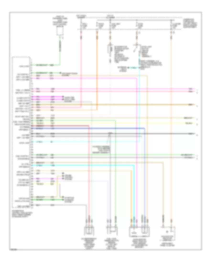
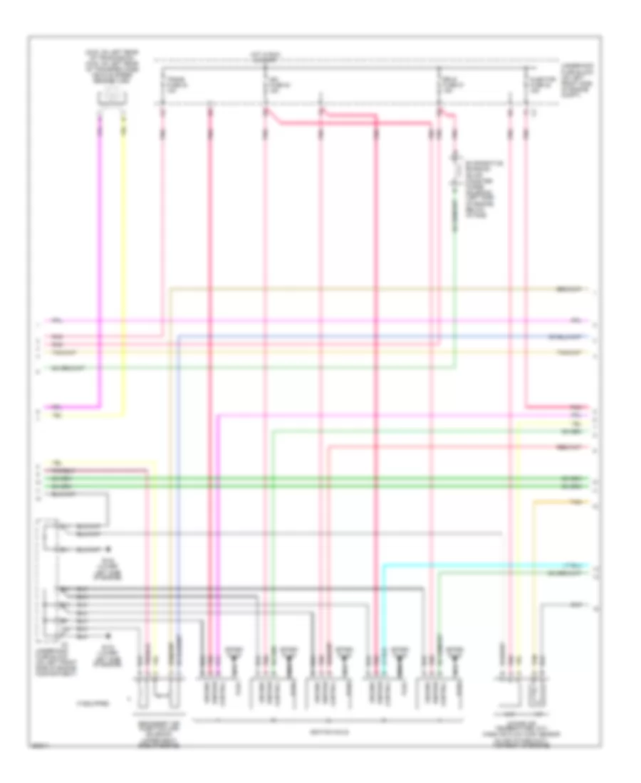
3.7L VIN E, Engine Performance Wiring Diagram (1 of 5) for GMC Canyon 2007
List of elements for 3.7L VIN E, Engine Performance Wiring Diagram (1 of 5) for GMC Canyon 2007:
- (body harness, 14.5 cm from accelerator pedal position switch breakout) s100
- (chassis harness, 39 cm before fuel pump & sender assembly)
- (part of transfer case) (4wd) transfer case shift control module
- 4wd lo sw
- A/c comp rly
- A/c press
- A/c refrigerant pressure sensor (right rear of engine compt)
- Accelerator pedal position (app) sensor (on accelerator bracket)
- Accy volt
- Air conditioning system
- Air pump rly
- App 1
- App 1 +5v ref
- App 1 low ref
- App 2
- App 2 +5v ref
- App 2 low ref
- App sens 1
- App sens 2
- Arp +5v ref
- Arp low ref
- Batt pos volt
- Can vent fuse 10a
- Class 2 data
- Cluster fuse 10a
- Computer data lines system
- Cpp sw sig
- Cruise control system
- Cruise ctrls
- Diag enable
- E11
- Evap vent sol
- Evaporative emission (evap) canister vent solenoid (on side of evap canister, above spare tire)
- Exterior lights system
- Ftp +5v ref
- Fuel lvl sens
- Fuel pump rly
- Fuel tank press
- Fuel tank pressure (ftp) sensor (at top left rear of fuel tank)
- Hot at all times
- Hot in run & start
- Ignition 1 volt
- Instrument panel cluster
- Iss sig
- Low ref
- Malfunction indicator lamp (mil)
- Mil ctrl
- Pcm 1 fuse 10a
- Pcm b fuse 10a
- Pnk
- Pnp/clutch sig
- Powertrain control module (pcm) (right rear corner of engine compt)
- S310
- Starter rly
- Starting/ charging system
- Stop fuse 20a
- Stop lamp
- Stop lamp switch (above brake pedal assembly)
- Tan
- Tcc brk sw
- Underhood fuse block (on left front side of engine compartment)
- Vehicle spd sig
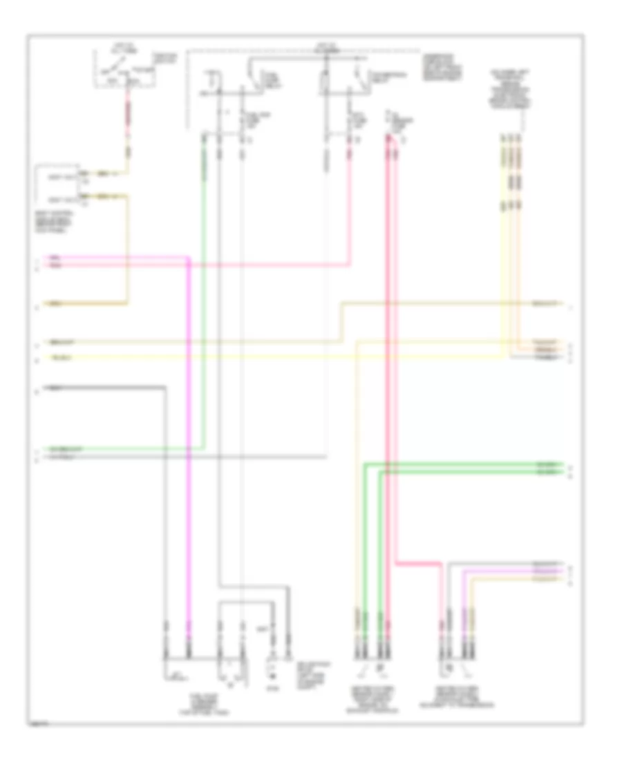
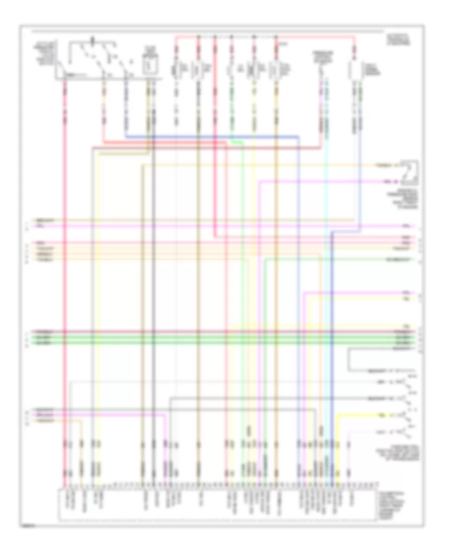
3.7L VIN E, Engine Performance Wiring Diagram (2 of 5) for GMC Canyon 2007
List of elements for 3.7L VIN E, Engine Performance Wiring Diagram (2 of 5) for GMC Canyon 2007:
- (2wd)
- (on inner left frame rail, beside transmission) electronic brake control module (ebcm)
- Acc
- Accy volt
- Air pump fuse 50a
- Air solenoid fuse block (if equipped) (lower right front of engine compartment)
- Air solenoid relay
- Battery
- Body control module (bcm) (behind right kick panel)
- Etc fuse 15a
- Fuel pmp fuse 15a
- Fuel pump & sender assembly (top of fuel tank)
- Fuel pump relay
- G101 (lower left side of engine)
- G105
- Heated oxygen sensor (ho2s) 1 (right side of engine, on exhaust manifold)
- Heated oxygen sensor (ho2s) 2 (in exhaust pipe, adjacent to transmission)
- Hot at all times
- Ignition switch
- Nca
- O2 sensor fuse 10a
- Off
- Pnk
- Powertrain relay
- Red
- Run
- S101 (in battery harness)
- S105
- S401
- Secondary air injection (air) pump relay (if equipped) (lower right front of engine compartment)
- Secondary air injection (air) pump relay (lower right front of engine compt)
- Splice pack sp105 (left side of engine compt)
- Start
- Underhood fuse block (on left front side of engine compartment)
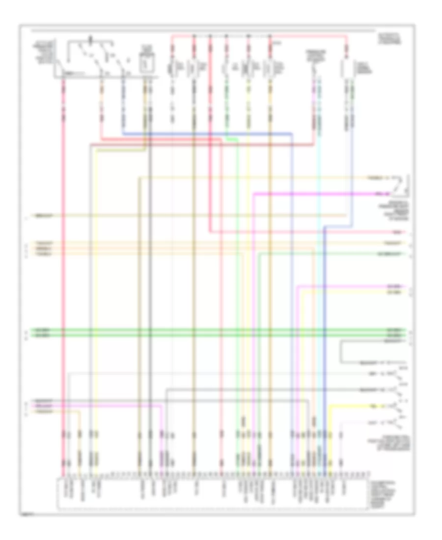
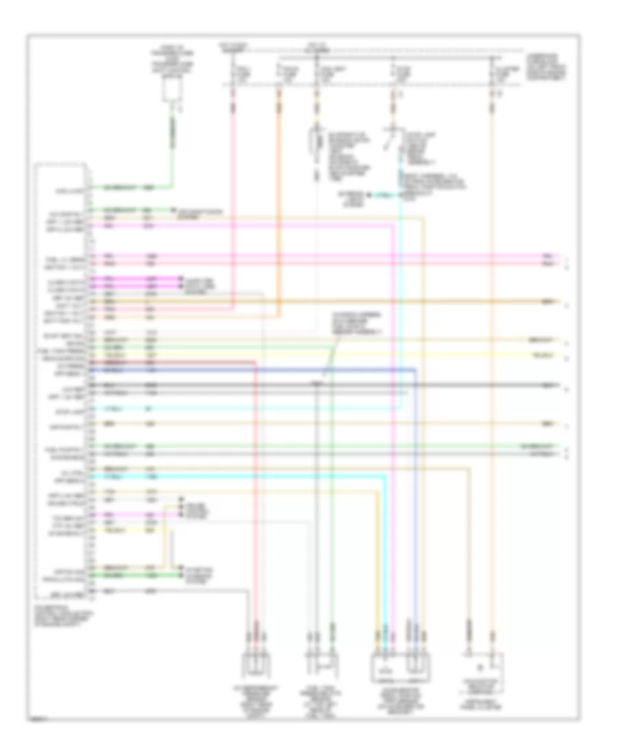
3.7L VIN E, Engine Performance Wiring Diagram (3 of 5) for GMC Canyon 2007
List of elements for 3.7L VIN E, Engine Performance Wiring Diagram (3 of 5) for GMC Canyon 2007:
- (2wd)
- 1-2 sol
- 2-3 sol
- 3-2 sol
- A/t fluid pressure manual valve position switch
- Air inj reac
- Automatic transaxle (if equpped)
- Del torque
- Engine oil pressure (eop) sensor (right front of engine)
- Evap purge
- Fluid temp sensor
- Ho2s 2 hi
- Ho2s 2 htr
- Ho2s 2 low
- Input speed sensor
- Iss low ref
- Low oil sw
- Low ref
- Oil press
- Park/neutral position (pnp) switch (on lower left side of transmission)
- Pc sol
- Pnk
- Powertrain control module (pcm) (right rear corner of engine compt)
- Pressure control solenoid
- Red
- Req torque
- Rev
- S133
- Tan
- Tcc pwm sol
- Tcc sol
- Tfp sw a
- Tfp sw b
- Tfp sw c
- Tft sens
- Tr sw a
- Tr sw b
- Tr sw p
- Tr sw sig
- Vss sig hi
- Vss sig low
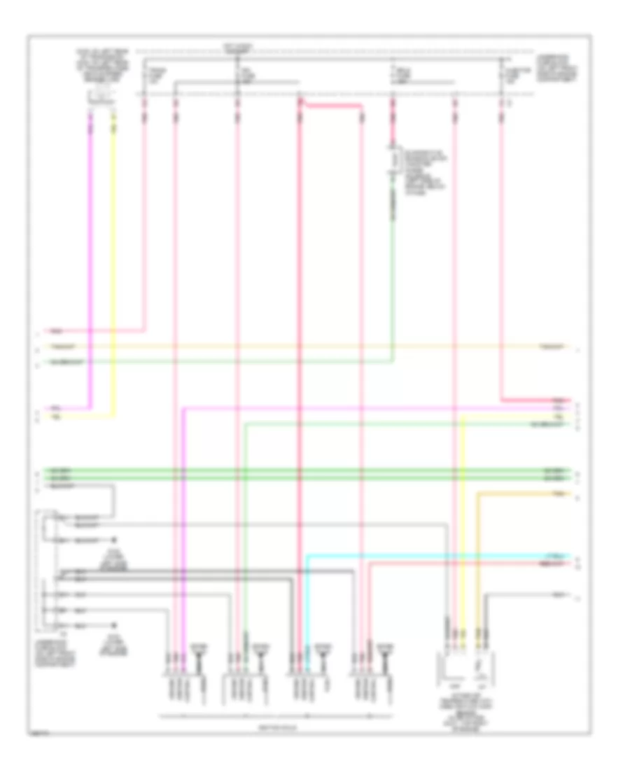
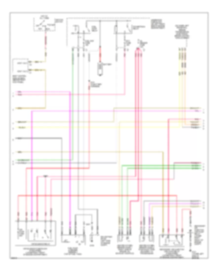
3.7L VIN E, Engine Performance Wiring Diagram (4 of 5) for GMC Canyon 2007
List of elements for 3.7L VIN E, Engine Performance Wiring Diagram (4 of 5) for GMC Canyon 2007:
- (2wd: on left rear of tranmission) (4wd: on left rear of transfer case) vehicle speed sensor (vss)
- B11
- C11
- Control
- D11
- E11
- Erls fuse 27 15a
- Evaporative emission (evap) canister purge solenoid (left side of engine, below intake)
- F11
- G102 (lower left side of engine)
- G103 (lower left side of engine)
- Ground
- Hot in run & start
- Iat
- If equipped
- Ign fuse 23 15a
- Ignition
- Ignition coils
- Injector fuse 22 15a
- Intake air temperature (iat)/ mass air flow (maf) sensor (in air intake duct, top right of engine)
- Maf
- Nca
- Plug
- Pnk
- Secondary air injection (air) solenoid (upper right side of engine)
- Spark plug
- Tan
- Trans fuse 24 10a
- Underhood fuse block (on left front side of engine compartment)
- Underhood fuse block (on left front side of engine compt)
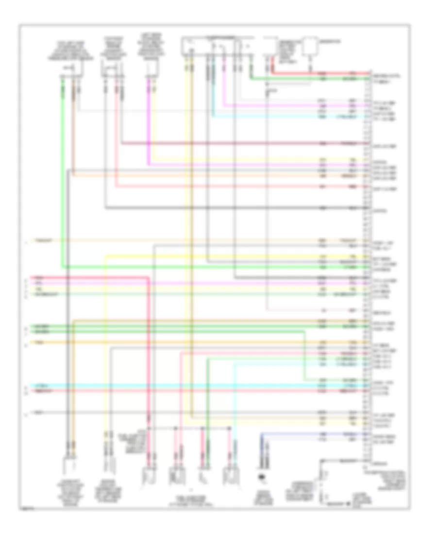
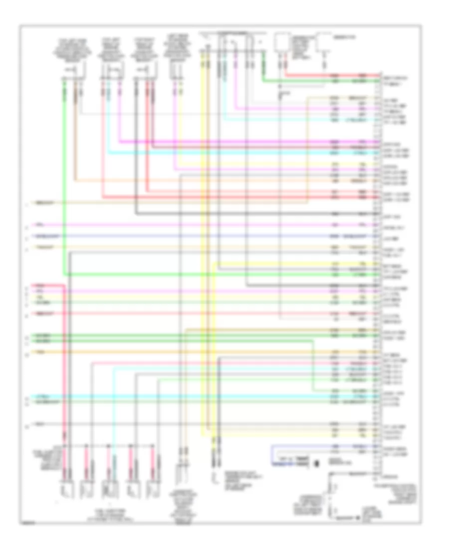
3.7L VIN E, Engine Performance Wiring Diagram (5 of 5) for GMC Canyon 2007
List of elements for 3.7L VIN E, Engine Performance Wiring Diagram (5 of 5) for GMC Canyon 2007:
- (left rear of engine block, below starter) crankshaft position (ckp) sensor
- (lower left side of engine) g102
- (top left front of engine) camshaft position (cmp) sensor 2
- (top left side of engine, on intake manifold) manifold absolute pressure (map) sensor
- (top right front of engine) camshaft position (cmp) sensor 1
- +5v ref
- A11
- Air sol rly
- B11
- Camshaft position (cmp) actuator solenoid bank 1 exhaust (on top right front of engine)
- Ckp low ref
- Ckp sig
- Cmp 1 sig
- Cmp 2 sig
- Cmp1 +12v ref
- Cmp1 low ref
- Cmp2 +12v ref
- Cmp2 low ref
- Cpa +5v ref
- Cpa low ref
- Ect low ref
- Ect sens
- Engine coolant temperature (ect) sensor (on left rear of engine)
- Fuel inj 1
- Fuel inj 2
- Fuel inj 3
- Fuel inj 4
- Fuel inj 5
- Fuel injectors (top of engine, attached to fuel rail)
- Gen field
- Gen turn-on
- Generator
- Generator battery control module (near battery)
- Ground
- Ho2s 1 high
- Ho2s 1 htr
- Ho2s 1 low
- Iat low ref
- Iat sens
- Ic 1 ctrl
- Ic 2 ctrl
- Ic 3 ctrl
- Ic 4 ctrl
- Ic 5 ctrl
- Knock sens
- Knock sensor (ks)
- Ks 1 low ref
- Low ref
- Maf sens
- Map +5v ref
- Map low ref
- Map sens
- Nca
- Pnk
- Pnk a
- Powertrain control module (pcm) (right rear corner of engine compt)
- Red
- S103 (fuel injector harness, 5 cm from fuel injector 4 breakout)
- Tac mtr 1
- Tac mtr 2
- Tan
- Throttle body
- Tp 1 +5v ref
- Tp 1 low ref
- Tp 2 +5v ref
- Tp 2 low ref
- Tp sens 1
- Tp sens 2
- Underhood fuse block (on left front side of engine compartment)
EXTERIOR LIGHTS
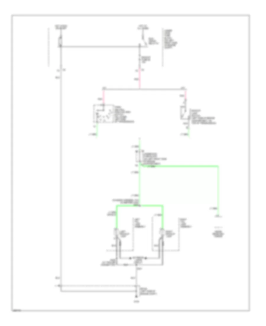
Back-up Lamps Wiring Diagram for GMC Canyon 2007
List of elements for Back-up Lamps Wiring Diagram for GMC Canyon 2007:
- (chassis harness, 75.5 cm before c402) s404
- A/t
- Backup fuse 26 15a
- Backup lamp switch (left side of engine compartment, on top of transmission)
- Exterior lamps circuit
- G105
- Hot at all times
- Hot in run or start
- Inside rearview mirror
- Left backup lamp
- Left tail lamp assembly
- M/t
- Nca
- Park/ neutral position (pnp) switch (on lower left side of transmission)
- Pnk
- Right backup lamp
- Right tail lamp assembly
- Run/ crank relay 61
- S401
- S409 (w/ trailer connection)
- Sp105 (left side of engine compt)
- Under- hood fuse block (on left front side of engine compt)
- Underhood fuse block (on left front side of engine compartment) c7
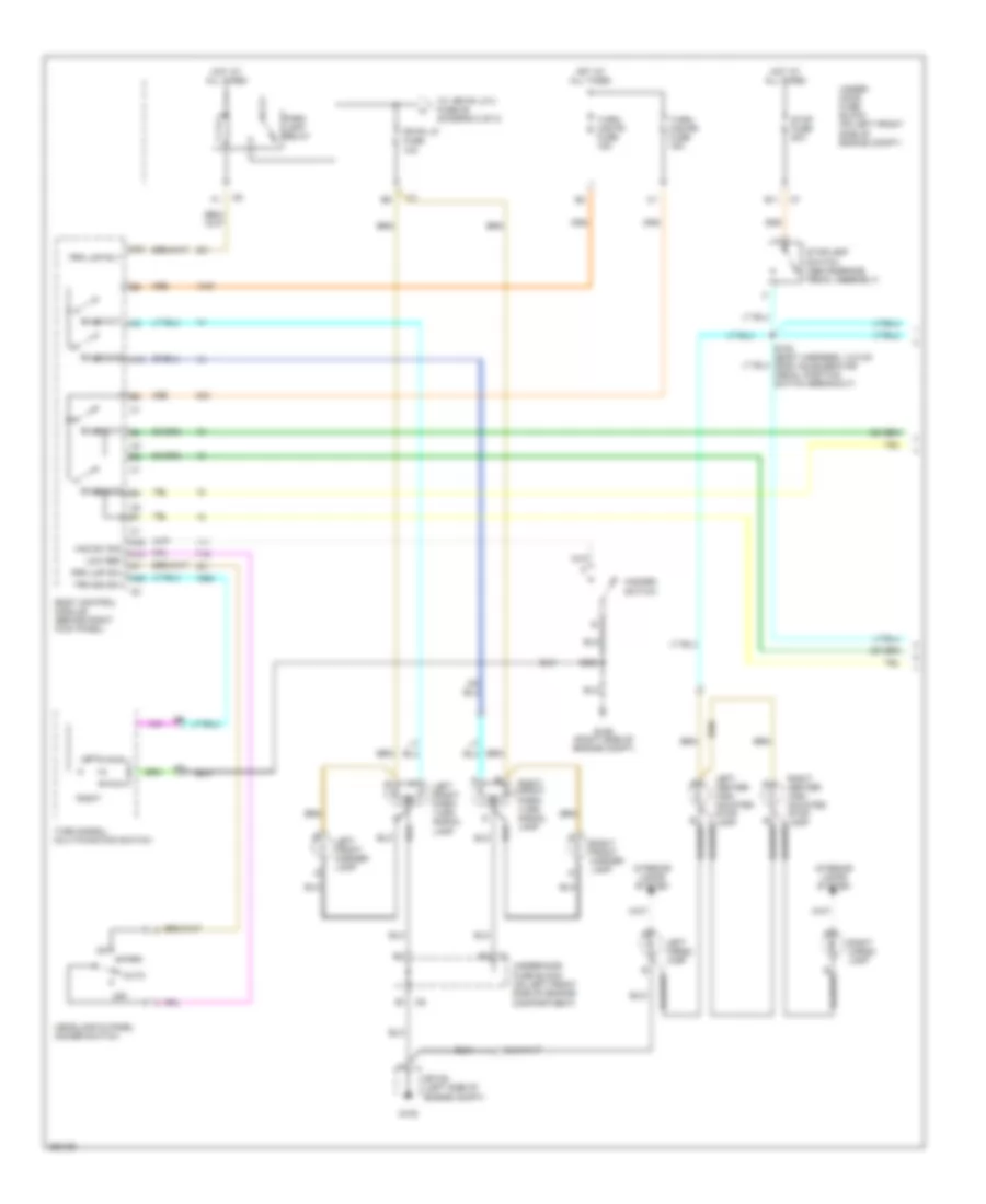
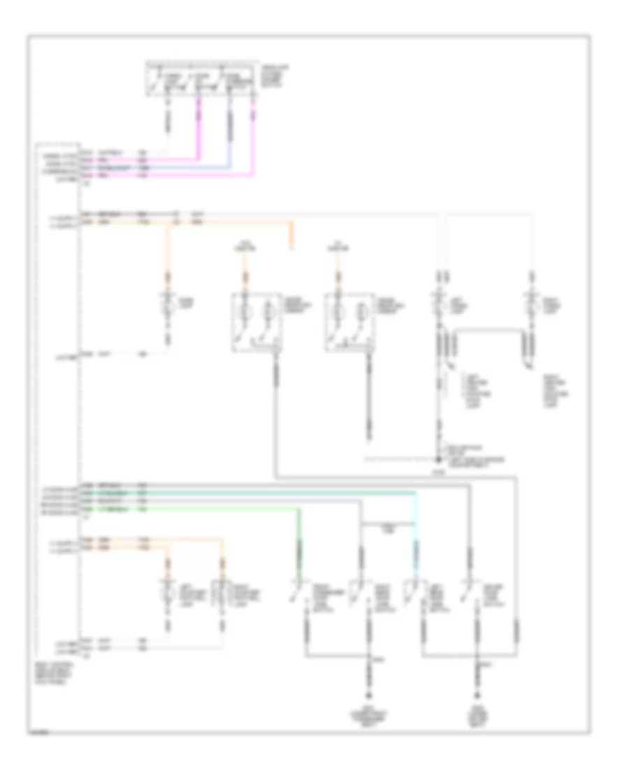
Exterior Lamps Wiring Diagram (1 of 2) for GMC Canyon 2007
List of elements for Exterior Lamps Wiring Diagram (1 of 2) for GMC Canyon 2007:
- A10
- A19
- A24
- A45
- A48
- Auto
- Body control module (behind right kick panel)
- Bulb out
- E11
- Fr pk lp fuse 10a
- G105
- G106 (right side of engine compt)
- Haz sw sig
- Hazard switch
- Headlamp & panel dimmer switch
- Hot at all times
- Interior lamps system
- Left
- Left cargo lamp
- Left front marker lamp
- Left front park/ turn signal lamp
- Low ref
- Off
- Park
- Park lamp relay
- Prk lmp rly
- Prk lmp sw
- Right
- Right cargo lamp
- Right front marker lamp
- Right front park/ turn signal lamp
- S200
- Sp105 (left side of engine compt)
- Stop fuse 20a
- Stoplamp switch (above brake pedal assembly)
- To rr pk lp 2 fuse 29 (diagram 2 0f 2)
- Trn sig sw
- Turn signal/ multi-function switch
- Turn/ haz fr fuse 15a
- Turn/ haz rr fuse 15a
- Under- hood fuse block (on left front side of engine compt)
- Underhood fuse block (on left front side of engine compartment)
Exterior Lamps Wiring Diagram (2 of 2) for GMC Canyon 2007
List of elements for Exterior Lamps Wiring Diagram (2 of 2) for GMC Canyon 2007:
- & c402 breakout) s403
- (chassis harness, 13 cm from c401 & c402 breakout) s402
- (license lamp harness, 44.5 cm before right license lamp) s900
- (not used)
- (w/ trailer connection) s408
- C401
- Electronic brake control module (ebcm) (on inner left frame rail, beside transmission)
- From a fr pk lp fuse 40 (diagram 1 0f 2)
- G105
- Grd
- Instrument panel cluster
- Left backup lamp
- Left license lamp
- Left rear stop lamp
- Left rear turn signal lamp
- Left tail lamp assembly
- Left turn ind
- Logic
- Lr trn sig
- Lr trn/stp lp
- Nca
- Powertrain control module (pcm) (right rear corner of engine compt)
- Prk lp
- Right backup lamp
- Right license lamp
- Right rear stop lamp
- Right rear turn signal lamp
- Right tail lamp assembly
- Right turn ind
- Rr pk lp 2 fuse 10a
- Rr pk lp fuse 15a
- Rr trn sig
- Rr trn/stp lp
- S400
- S401
- S405 (w/ trailer connection)
- S406 (w/ trailer connection)
- S407 (w/ trailer connection)
- S409
- S409 (w/ trailer connection)
- S901
- Sp105 (left side of engine compartment)
- Stp lmp vlt
- Stp lp sw sig
- Trailer connector
- Trailer lighting converter
- Under- hood fuse block (on left front side of engine compt)
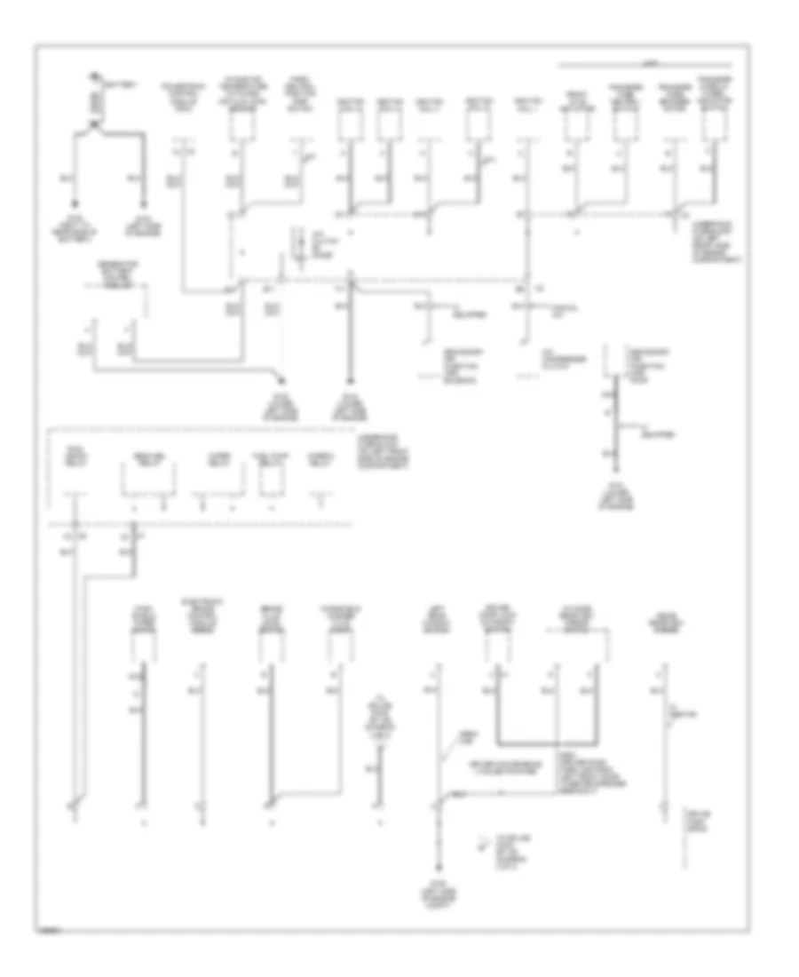
GROUND DISTRIBUTION
Ground Distribution Wiring Diagram (1 of 3) for GMC Canyon 2007
List of elements for Ground Distribution Wiring Diagram (1 of 3) for GMC Canyon 2007:
- 3.7l
- 4wd
- A/c clutch diode
- A/c compressor clutch
- A/t
- A11
- B11
- Battery
- Beam sel relay
- Brake fluid level switch
- C11
- Crew cab
- D11
- Driver convenience iii sales package
- Driver door lock & window switch
- E11
- Electronic brake control module (ebcm)
- F11
- Front axle actuator
- Fuel pump relay
- G100 (next to rear side of battery)
- G101 (lower left side of engine)
- G102 (lower left side of engine)
- G103 (lower left side of engine)
- G104 (left side of engine)
- G105 (left side of engine compt)
- Generator battery control module
- If equipped
- Ignition coil 1
- Ignition coil 2
- Ignition coil 3
- Ignition coil 4
- Ignition coil 5
- Inside rearview mirror
- Intake air temperature (iat)/mass air flow (maf) sensor
- Left rear window switch
- Manual a/c
- Nca
- Outside rearview mirror switch
- Park/ neutral position (pnp) switch
- Powertrain control module (pcm)
- Run/ crank relay
- S500 (driver door harn, 5cm from left front door tweeter speaker breakout)
- Secondary air injection (air) pump
- Secondary air injection (air) solenoid
- Splice pack sp105
- To splice pack sp 105 (diagram 2 of 3)
- To splice pack sp 106 (diagram 2 of 3)
- Transfer case 2/4 wheel indicator switch
- Transfer case encoder motor
- Transfer case neutral switch
- Underhood fuse block (on left front side of engine compartment)
- W/ onstar
- Wind- shield wiper motor
- Windshield washer fluid pump
- Wiper 2 relay
- Wiper relay
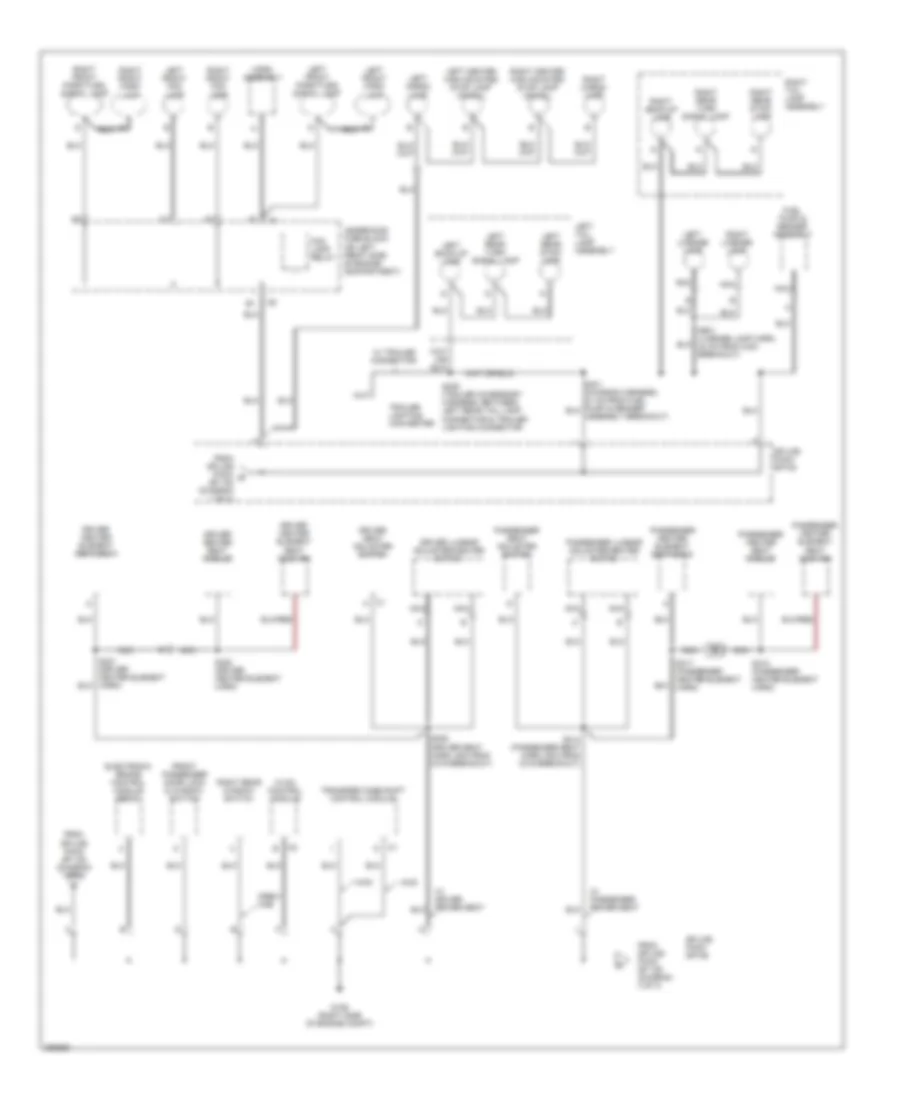
Ground Distribution Wiring Diagram (2 of 3) for GMC Canyon 2007
List of elements for Ground Distribution Wiring Diagram (2 of 3) for GMC Canyon 2007:
- 4wd
- C1 h
- Crew cab
- Driver heater element seat back
- Driver heater element seat cushion
- Driver heater seat module
- Driver lumbar adjuster/heater switch
- Driver seat adjuster switch
- Electronic brake control module (ebcm)
- Fog lamp relay
- From splice pack b sp 105 (diagram 1 of 3)
- From splice pack sp 105 (diagram 1 of 3)
- From splice pack sp 106 (diagram 3 of 3)
- Front passenger door lock & window switch
- Fuel pump & sender assembly
- G106 (right side of engine compt)
- Horn assembly
- Hvac control module
- Left back-up lamp
- Left cargo lamp
- Left center high mounted stop lamp (chmsl)
- Left front fog lamp
- Left front park lamp
- Left front park/turn signal lamp
- Left license lamp
- Left rear stop- lamp
- Left rear turn signal lamp
- Left tail lamp assembly
- Nca
- Passenger heater element seat back
- Passenger heater element seat cushion
- Passenger heater seat module
- Passenger lumbar adjuster/heater switch
- Passenger seat adjuster switch
- Right back-up lamp
- Right cargo lamp
- Right center high mounted stop lamp (chmsl)
- Right front fog lamp
- Right front park lamp
- Right front park/turn signal lamp
- Right license lamp
- Right rear stop- lamp
- Right rear turn signal lamp
- Right rear window switch
- Right tail lamp assembly
- S306 (driver seat harn, 5cm from c319 breakout)
- S314 (passenger seat harn, 5cm from c319 breakout)
- S317 (passenger heater element harn)
- S318 (passenger heater element harn)
- S321 (driver heater element harn)
- S322 (driver heater element harn)
- S409 (trailer accessory harness, between left rear tail lamp connector & trailer lighting connector
- S901 (license lamp harn, 24 cm from c400 breakout)
- Splice pack sp105
- Splice pack sp106
- Trailer lighting converter
- Transfer case shift control module
- Underhood fuse block (on left front side of engine compartment)
- W/ driver power seat
- W/ passenger power seat
- W/ trailer connector
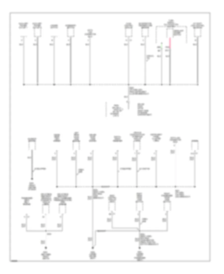
Ground Distribution Wiring Diagram (3 of 3) for GMC Canyon 2007
List of elements for Ground Distribution Wiring Diagram (3 of 3) for GMC Canyon 2007:
- (between front seats)
- (front center of roof)
- (right side of engine compartment)
- A/t shift lock control solenoid
- Accessory switch
- Auxiliary power outlet 1
- Auxiliary power outlet 2
- B10
- Body control module (bcm)
- C1 a12
- C1 b3
- Crew cab
- Data link connector (dlc)
- Digital radio receiver
- Driver door jamb switch
- Evaporator temperature sensor
- From splice pack c sp 106 (diagram 3 of 3)
- Front passenger door jamb switch
- G300 (under driver seat)
- G301 (under front passenger seat)
- G302
- G303
- Hazard switch
- Headlamp dimmer switch
- Hvac control module
- If equipped
- Inflatable restraint front passenger presense system (pps) module
- Inflatable restraint sensing & diagnostic module (sdm)
- Inside rear view mirror
- Instrument panel cluster (ipc)
- Left rear door jamb switch
- Manual a/c
- Passenger seat belt buckle
- Pnk
- Radio
- Right rear door jamb switch
- S200 (i/p harn, 6cm from instrument cluster breakout)
- S201 (i/p harn, 7cm from c204 breakout)
- S324
- Splice pack sp106
- Sunroof switch
- Turn signal/ multifunction switch
- Vehicle communication interface module (vcim)
- W/ onstar
HEADLIGHTS
Headlights Wiring Diagram for GMC Canyon 2007
List of elements for Headlights Wiring Diagram for GMC Canyon 2007:
- A10
- A11
- A18
- A31
- A36
- A37
- A39
- A43
- Ambient light sensor
- Ambient lt sens
- Auto
- B10
- Beam sel relay
- Bm sel rly ctrl
- Body control module (behind right kick panel)
- C1 c2
- C7 c10
- Class 2 data
- Class 2 ser data
- Class 2 serial data
- Drl fuse 10a
- Drl ind
- Drl relay
- Drl relay ctrl
- Flash to pass
- Fog lmp ind
- Fog lp fuse 15a
- Fog lp relay
- Fog lp rly ctrl
- Fog lp sw sig
- Front fog lamp ind
- Front fog lamp switch
- G105
- G106
- Ground distribution system
- Hdlp dim sw sig
- Hdlp off sig
- Hdlp on sig
- Hdlp relay
- Hdlp rly ctrl
- Headlamp & panel dimmer switch
- Headlamp dimmer switch
- High beam
- High beam ind
- Hot at all times
- Ign
- Instrument panel cluster
- Left front fog lamp
- Left high beam head- lamp
- Left low beam head- lamp
- Lh hdlp fuse 10a
- Low ref
- Off
- Park
- Park brake switch (lower left end of dash)
- Pk brake sig
- Pnk
- Red
- Rh hdlp fuse 10a
- Right front fog lamp
- Right high beam head- lamp
- Right low beam head- lamp
- S200
- Sp105 (left side of engine compt)
- Sp106 (right side of engine compt)
- Turn signal/ multifunction switch
- Underhood fuse block (on left front side of engine compt)
HORN
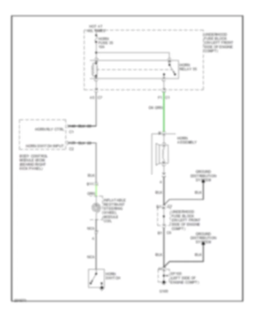
Horn Wiring Diagram for GMC Canyon 2007
List of elements for Horn Wiring Diagram for GMC Canyon 2007:
- A25
- A40
- A5 c7
- B11
- Body control module (bcm) (behind right kick panel)
- F1 c1
- G105
- Ground distribution system
- Horn assembly
- Horn fuse 35 10a
- Horn relay 55
- Horn rly ctrl
- Horn switch
- Horn switch input
- Hot at all times
- Inflatable restraint steering wheel module coil
- Nca
- Sp105 (left side of engine compt)
- Underhood fuse block (on left front side of engine compt)
INSTRUMENT CLUSTER
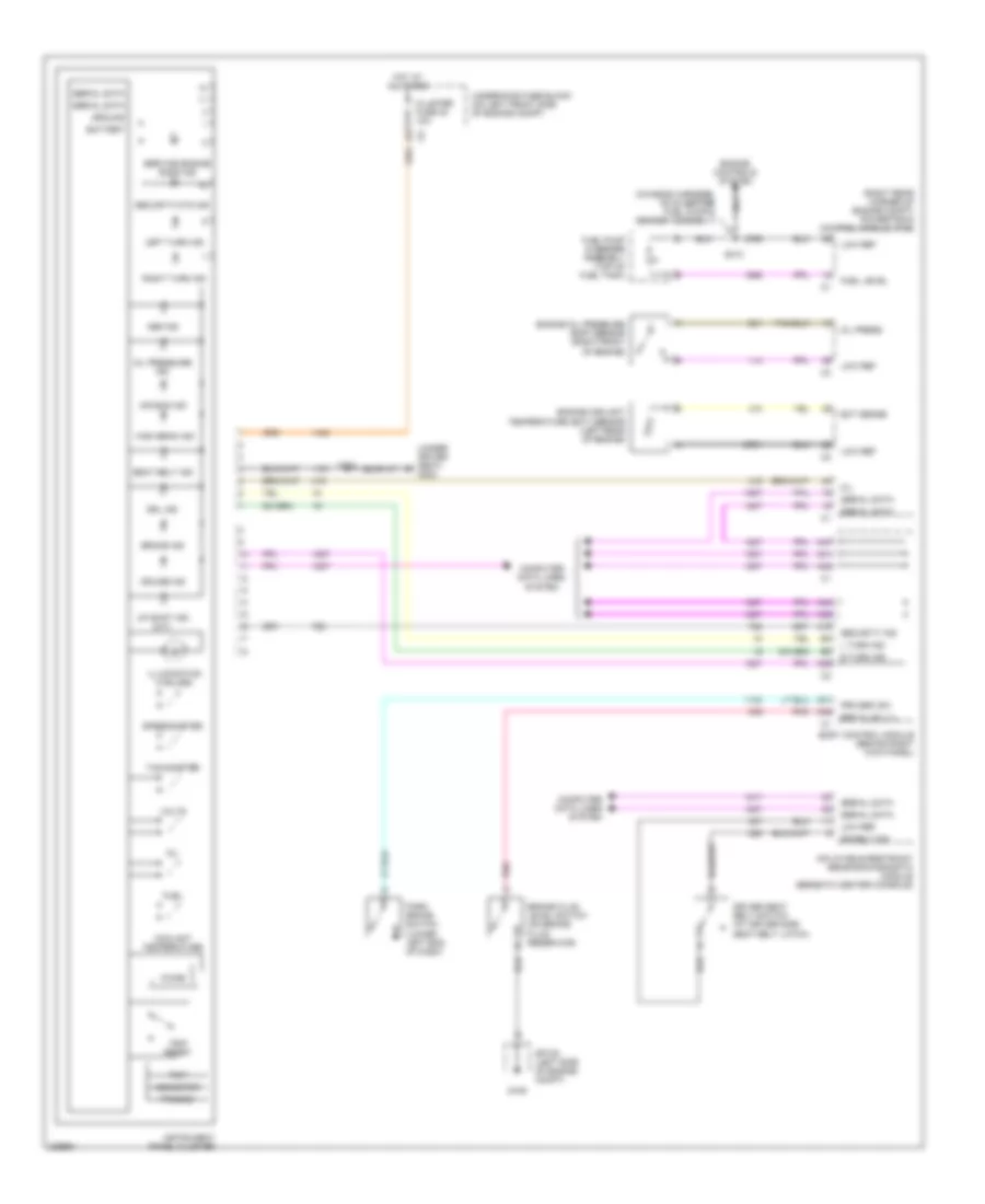
Instrument Cluster Wiring Diagram for GMC Canyon 2007
List of elements for Instrument Cluster Wiring Diagram for GMC Canyon 2007:
- (chassis harness, 39 cm before fuel pump & sender assembly)
- (right rear corner of engine compt) powertrain control module (pcm)
- (under driver seat) g300
- A19
- A31
- A38
- A39
- A41
- A42
- A44
- A45
- A47
- Abs ind
- Air bag ind
- Battery
- Body control module (behind right kick panel)
- Brake fluid level switch (on brake fluid reservoir)
- Brake ind
- Brk fluid lvl
- Chime
- Cluster fuse 38 10a
- Computer data lines system
- Coolant temperature
- Cruise ind
- Dr belt sw
- Driver seat belt switch (at driver side seat belt latch)
- Drl ind
- Ect sense
- Engine controls system
- Engine coolant
- Engine oil pressure (eop) sensor (right front of engine)
- Fuel
- Fuel level
- Fuel pump & sender assembly (top of fuel tank)
- G105
- Ground
- High beam ind
- Hot at all times
- Illumination (4 bulbs)
- Inflatable restraint sensing/diagnostic module (beneath center console)
- Instrument panel cluster
- L turn ind
- Left turn ind
- Low ref
- Mil
- Odometer
- Oil
- Oil press
- Oil pressure ind
- Park brake switch (lower left end of dash)
- Pnk
- Prk brk sw
- Prnd321
- R turn ind
- Right turn ind
- S201
- S310
- Seat belt ind
- Security ind
- Security/ctd ind
- Serial data
- Service engine soon ind
- Sp105 (left side of engine compt)
- Speedometer
- Tachometer
- Temperature (ect) sensor (left rear of engine)
- Trip
- Trip reset
- Underhood fuse block (on left front side of engine compt)
- Up shift ind (m/t)
- Volts
INTERIOR LIGHTS
Courtesy Lamps Wiring Diagram for GMC Canyon 2007
List of elements for Courtesy Lamps Wiring Diagram for GMC Canyon 2007:
- A10
- A11
- A12
- A13
- A30
- A32
- A38
- A39
- A40
- A41
- A44
- A46
- A47
- Body control module (bcm) (behind right kick panel)
- Cargo lamp switch
- Cargo lp sw
- Crew cab
- Dome lamp
- Dome lp sw
- Dome on switch
- Dome override switch
- Driver door jamb switch
- Front passenger door jamb switch
- G105
- G300 (under driver seat)
- G301 (under front passenger seat)
- Headlamp & panel dimmer switch
- Inside rearview mirror
- Left cargo lamp
- Left center high mounted stop lamp
- Left courtesy footwell lamp
- Left rear door jamb switch
- Lf door ajar
- Low ref
- Lr door ajar
- Override sw
- Rf door ajar
- Right cargo lamp
- Right center high mounted stop lamp
- Right courtesy footwell lamp
- Right rear door jamb switch
- Rr door ajar
- S304
- Splice pack sp105 (left side of engine compartment)
- W/ onstar
- W/o onstar
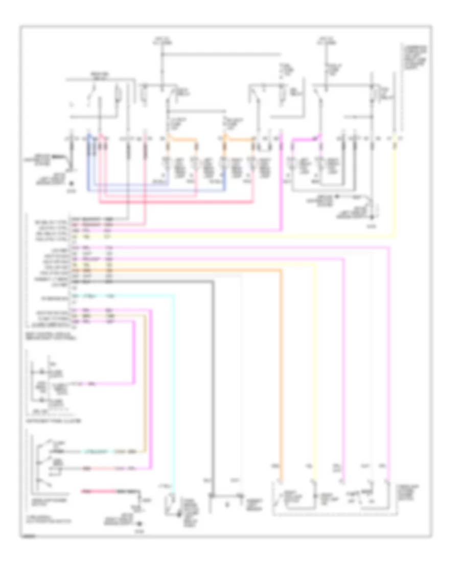
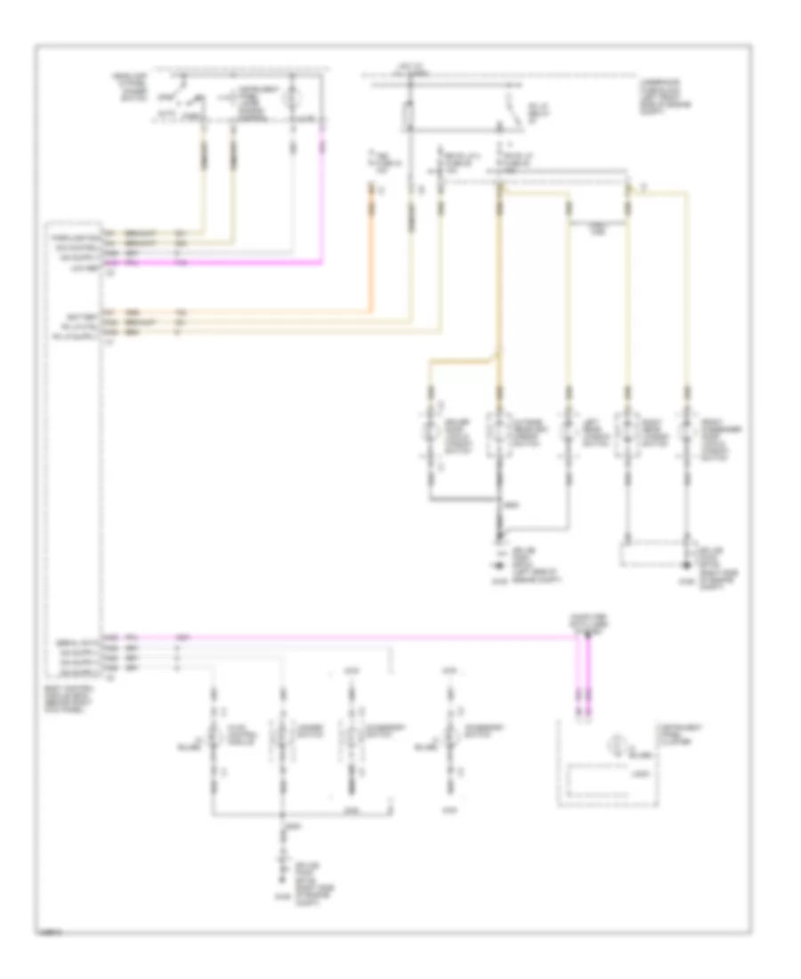
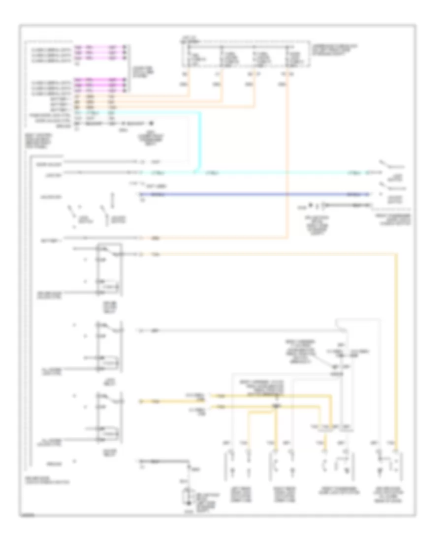
Instrument Illumination Wiring Diagram for GMC Canyon 2007
List of elements for Instrument Illumination Wiring Diagram for GMC Canyon 2007:
- (3 bulbs)
- (4 bulbs)
- (5 bulbs)
- 2wd
- 4wd
- A10
- A24
- A28
- A29
- A35
- A36
- A39
- A48
- Accessory switch
- Auto
- Battery
- Body control module (bcm) (behind right kick panel)
- C11
- Computer data lines system
- Crew cab
- Dim control
- Driver door lock & window switch
- F11
- Fr pk lp fuse 40 10a
- Front passenger door lock & window switch
- G105
- G106
- Hazard switch
- Headlamp & panel dimmer switch
- Hot at all times
- Hvac control module
- Illum
- Instrument panel cluster
- Instrument panel lamps dimming control
- Left rear window switch
- Logic
- Low ref
- Off
- Outside rearview mirror switch
- Park
- Parklamp sig
- Pk lp ctrl
- Pk lp relay
- Right rear window switch
- Rr pk lp 2 fuse 29 10a
- S200
- S500
- Serial data
- Splice pack sp105 (left side of engine compt)
- Splice pack sp106 (right side of engine compt)
- Tbc fuse 34 10a
- Underhood fuse block (left front side of engine compt)
POWER DISTRIBUTION
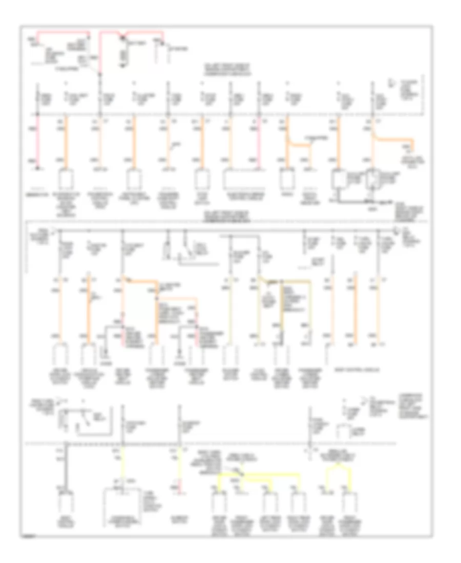
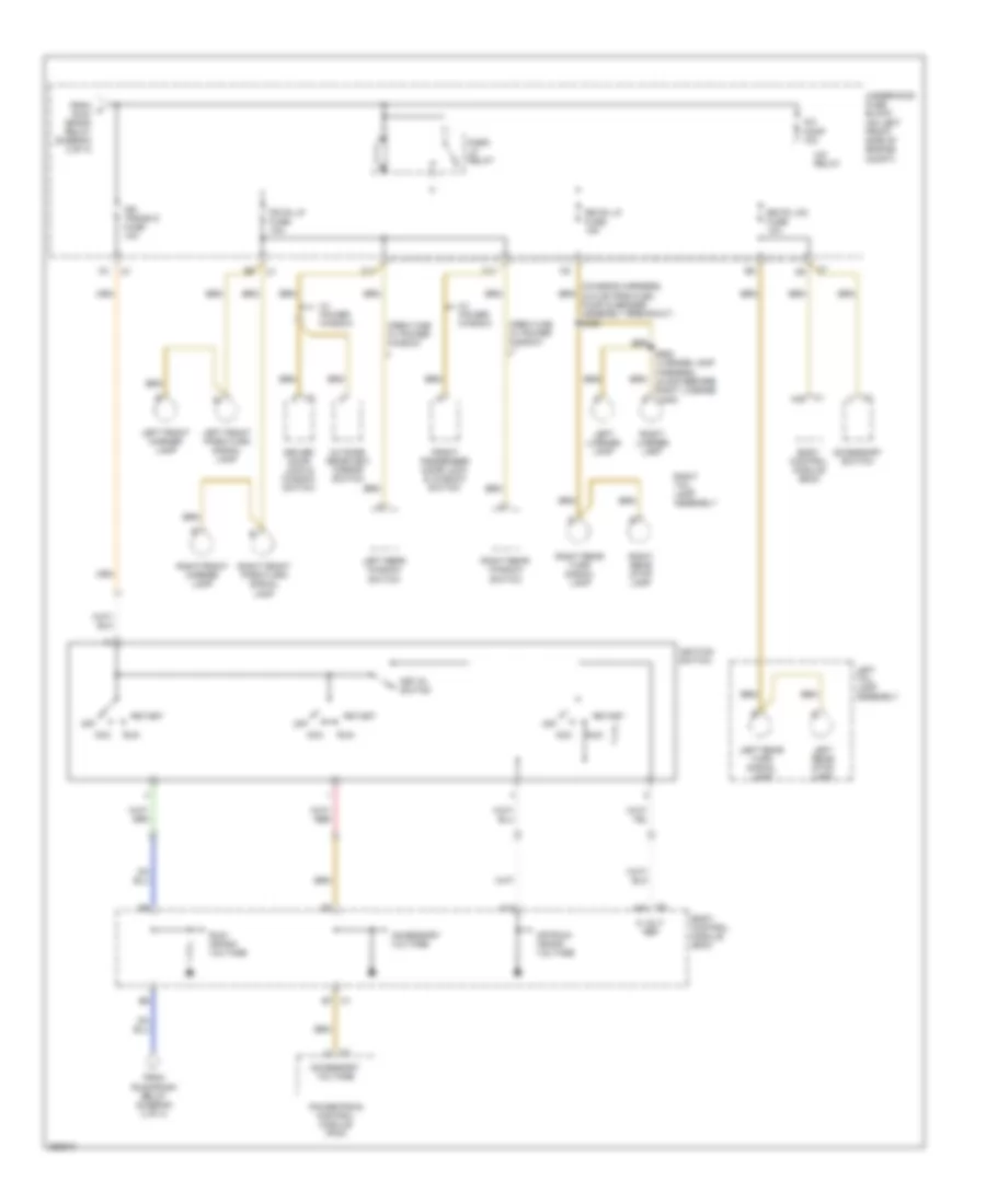
Power Distribution Wiring Diagram (1 of 4) for GMC Canyon 2007
List of elements for Power Distribution Wiring Diagram (1 of 4) for GMC Canyon 2007:
- (body harn, 4 cm from accelerator pedal position switch breakout)
- (on left front side of engine compartment) underhood fuse block
- 4wd
- A/c fuse 10a
- A10
- Abs 1 fuse 30a
- Abs 2 fuse 40a
- Air solenoid fuse block
- Aux pwr 1 fuse 20a
- Aux pwr 2 fuse 20a
- Auxiliary power outlet
- B10
- B11
- Battery
- Blower fuse 30a
- Blower motor switch
- Body control module
- C204
- Can vent fuse 10a
- Cluster fuse 10a
- Crew cab w/ power window
- Data link connector (dlc)
- Digital radio receiver
- Diode
- Door lock fuse 20a
- Driver door lock & window switch
- Driver heated seat module
- Driver lumbar adjuster/ heater switch
- E11
- Electronic brake control module
- Evaporative emission (evap) canister vent solenoid
- F12
- From a aux fuse (diagram 1 of 4)
- From turn/ b haz rr fuse (diagram 1 of 4)
- Front passenger door lock & window switch
- G106 (right side of engine compt, behind air cleaner)
- Generator
- Htd seat fuse 20a
- Hvac control module
- If equipped
- Ign 3 hvac relay
- Instrument panel cluster (ipc)
- Left rear door lock & window switch
- Mega fuse 100a
- Nca
- Onstar fuse 10a
- Passenger heated seat module
- Passenger lumbar adjuster/ heater switch
- Pcm b fuse 10a
- Powertrain control module (pcm)
- Pwr/ window fuse 30a
- Radio
- Radio fuse 15a
- Rap relay
- Red
- Regular, extended cab w/ power window
- Right rear door lock & window switch
- S101 (battery harness)
- S200
- S300 (body harness, 5 cm from g300 breakout)
- S302
- S313 (pass seat harn, 12.5cm from c318 breakout)
- S315 (driver heater element harness)
- S319 (passenger heater element harness)
- Start fuse 30a
- Start relay
- Starter
- Stop fuse 20a
- Stop lamp switch
- Sunroof fuse 20a
- Sunroof switch
- Tbc fuse 10a
- Tccm fuse 10a
- To door lock fuse (diagram 1 of 4)
- To powertrain relay (diagram 2 of 4)
- To rap relay (diagram 1 of 4)
- Transfer case shift control module
- Turn signal/ multi- function switch
- Turn/ haz fr fuse 15a
- Turn/ haz rr fuse 15a
- Underhood fuse block (on left front side of engine compartment)
- Vehicle communication interface module (vcim)
- W/ 6-way power seat
- W/ gps 1
- W/ heated seats
- Windshield wiper/washer switch
- Wip/wash fuse 10a
- Wiper fuse 25a
- Wiper relay
Power Distribution Wiring Diagram (2 of 4) for GMC Canyon 2007
List of elements for Power Distribution Wiring Diagram (2 of 4) for GMC Canyon 2007:
- (automatic transmission harness) s133
- (driver seat harness, 12.5 cm from c319 breakout) s312
- (not used)
- (w/ gps)
- (w/ outside display)
- 1-2 shift solenoid valve
- 2-3 shift solenoid valve
- 3-2 shift solenoid valve
- 4wd
- A/t
- Accessory switch
- Airbag fuse 10a
- Clutch switch (m/t)
- Cruise fuse 10a
- Driver lumbar adjuster/ heater switch
- Driver seat adjuster switch
- Drl fuse 10a
- Drl relay
- Fog lp fuse 15a
- Fog lp relay
- From fuel d pump relay (diagram 2 of 4)
- From wiper c fuse (diagram 1 of 4)
- Fuel pump relay
- G105
- Generator battery control module
- Hdlp relay
- Horn fuse 10a
- Horn relay
- Inflatable restraint front passenger presence system (pps) module
- Inflatable restraint sensing & diagnostic module (sdm)
- Inside rearview mirror
- Nca
- Passenger seat adjuster switch
- Pnk
- Powertrain relay
- Pwr/seat fuse 40a
- Red
- Run/ crank relay
- Rvc fuse 10a
- Seat fuse holder 20a
- Sp105 (left side of engine compt)
- Tcc brake/ cruise release switch
- To backup fuse (diagram 3 of 4)
- To body control module (diagram 4 of 4)
- To park lp relay (diagram 4 of 4)
- To run/ crank relay (diagram 2 of 4)
- Torque converter clutch (tcc) solenoid valve
- Torque converter clutch pulse width modulation (tcc pwm) solenoid valve
- Trans fuse 10a
- Transfer case shift control module
- Turn signal/ multifuction switch
- Underhood fuse block (on left front side of engine compt)
- W/ 6-way power seat
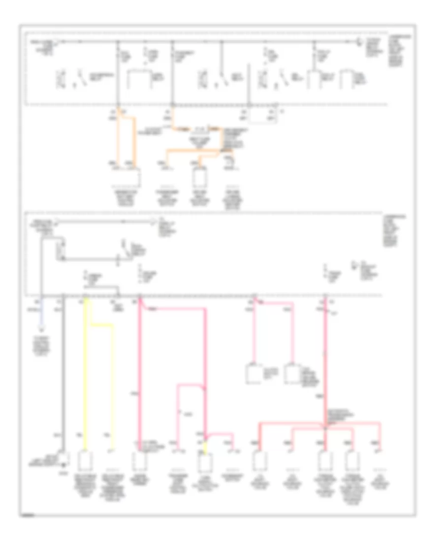
Power Distribution Wiring Diagram (3 of 4) for GMC Canyon 2007
List of elements for Power Distribution Wiring Diagram (3 of 4) for GMC Canyon 2007:
- (fuel injector harn, 4cm from fuel injector 4 breakout) s104
- (fuel injector harn, 5cm from fuel injector 4 breakout) s103
- 2.9l
- 3.7l
- 4wd
- A/c comp relay
- A/t
- Abs fuse 10a
- Back-up lamp switch
- Backup fuse 15a
- C2 b2
- C2 c3
- C2 f4
- C7 f3
- Clutch start switch
- Electronic brake control module (ebcm)
- Erls fuse 15a
- Evaporative emission (evap) canister purge solenoid
- From ign g fuse 23 (diagram 3 of 4)
- From trans e fuse 24 (diagram 2 of 4)
- Front axle actuator
- Frt ax fuse 15a
- Fuel injector
- If equipped
- Ign fuse 15a
- Ignition coil 1
- Ignition coil 2
- Ignition coil 3
- Ignition coil 4
- Ignition coil 5
- Injector fuse 15a
- Intake air temperature (iat)/mass air flow (maf) sensor
- Longitudinal accelerometer sensor
- M/t
- Park/ neutral position (pnp) switch
- Pcm i fuse 10a
- Pnk
- Pnk pnk
- Powertrain control module (pcm)
- Secondary air injection (air) pump relay
- To erls fuse 27 (diagram 3 of 4)
- Underhood fuse block (on left front side of engine compartment)
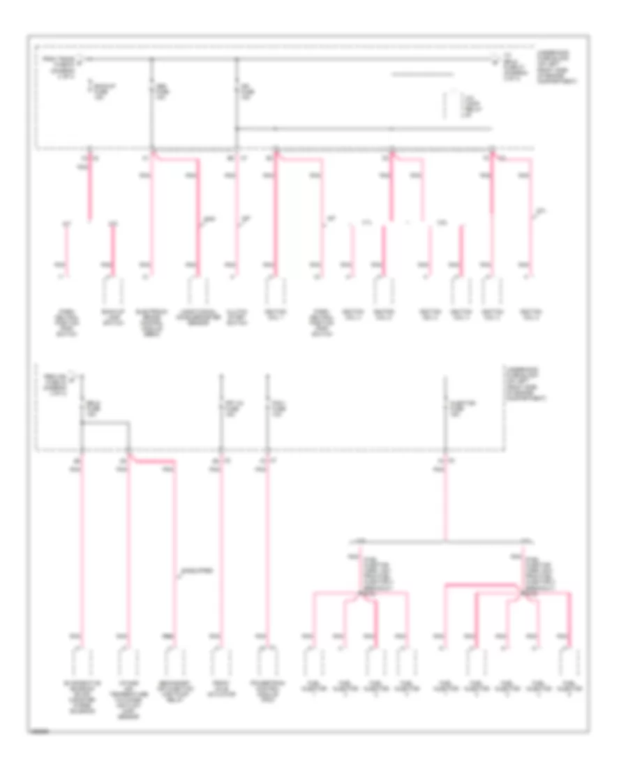
Power Distribution Wiring Diagram (4 of 4) for GMC Canyon 2007
List of elements for Power Distribution Wiring Diagram (4 of 4) for GMC Canyon 2007:
- (chassis harness, 40.5 cm from fuel pump & sender assembly breakout) s400
- 5 volt ref
- A/c comp 10a
- A/c relay
- A14
- Acc
- Accessory switch
- Accessory voltage
- Body control module (bcm)
- C1 a48
- C1 b7
- C11
- C2 a42
- C2 c
- Crew cab w/ power window
- Driver door lock & window switch
- F11
- Fr pk lp fuse 10a
- From f run/ crank relay (diagram 2 of 4)
- From run/crank relay (diagram 2 of 4)
- Front passenger door lock & window switch
- Ign trans d fuse 10a
- Ignition switch
- Key-in switch
- Left front marker lamp
- Left front park/turn signal lamp
- Left license lamp
- Left rear stop lamp
- Left rear turn signal lamp
- Left rear window switch
- Left tail lamp assembly
- Off
- Off/run/ crank voltage
- Outside rearview mirror switch
- Park lp relay
- Powertrain control module (pcm)
- Right front marker lamp
- Right front park/turn signal lamp
- Right license lamp
- Right rear stop lamp
- Right rear turn signal lamp
- Right rear window switch
- Right tail lamp assembly
- Rr pk lp fuse 15a
- Rr pk lp2 fuse 10a
- Run
- Run/ crank voltage
- S900 (license lamp harness, 44.5cm before right license lamp)
- Start
- Underhood fuse block (on left front side of engine compt)
- W/ power window
POWER DOOR LOCKS
Power Door Locks Wiring Diagram for GMC Canyon 2007
List of elements for Power Door Locks Wiring Diagram for GMC Canyon 2007:
- (body harness, 10.5 cm from accelerator pedal position switch breakout)
- (body harness, 17 cm from accelerator pedal position switch breakout)
- (not used)
- 87a
- A11
- A12
- A38
- A39
- A41
- A42
- A44
- A47
- All doors lock ctrl
- All doors unlock ctrl
- Battery +
- Body control module (bcm) (behind right kick panel)
- C7 b3
- Class 2 serial data
- Computer data lines system
- Door lock fuse 21 20a
- Door unlock
- Door unlock ctrl
- Driver door lock & window switch
- Driver door lock actuator (in lower rear of door)
- Driver door unlock ctrl
- Driver unlock relay
- F5 c6
- Front passenger door lock & window switch
- Front passenger door lock actuator
- G105
- G106
- G301 (under front passenger seat)
- Ground
- Hot at all times
- Left rear door lock actuator (crew cab)
- Lock relay
- Lock sw
- Lock switch
- Pass door lock ctrl
- Right rear door lock actuator (crew cab)
- S304
- S308
- S309
- S500
- Splice pack sp105 (left side of engine compt)
- Splice pack sp106 (right side of engine compt)
- Tan
- Tbc fuse 34 10a
- Turn/ haz fr fuse 37 15a
- Turn/ haz rr fuse 28 15a
- Underhood fuse block (on left front side of engine compt)
- Unlock relay
- Unlock sw
- Unlock switch
- W/ crew cab
- W/o crew cab
POWER MIRRORS
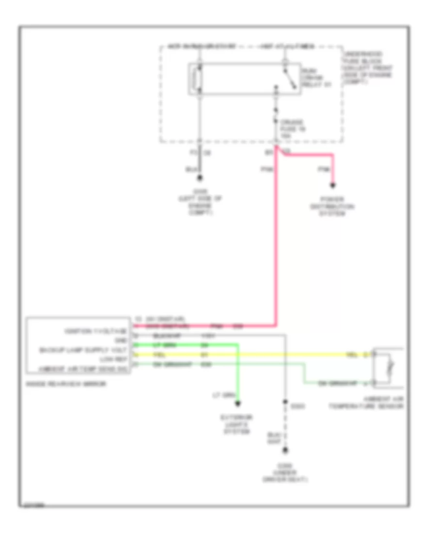
Automatic Day/Night Mirror Wiring Diagram for GMC Canyon 2007
List of elements for Automatic Day/Night Mirror Wiring Diagram for GMC Canyon 2007:
- (w/ onstar) (w/o onstar)
- Ambient air temp sens sig
- Ambient air temperature sensor
- Cruise fuse 19 10a
- Exterior lights system
- F3 c6
- G105 (left side of engine compt)
- G300 (under driver seat)
- Gnd
- Hot at al times
- Hot in run or start
- Ignition 1 voltage
- Inside rearview mirror
- Low ref
- Pnk
- Power distribution system
- Run/ crank relay 61
- S303
- Underhood fuse block (on left front side of engine compt)
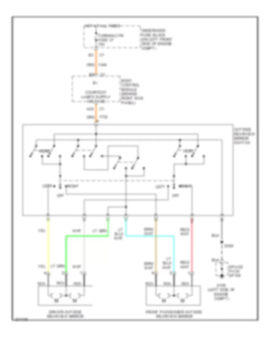
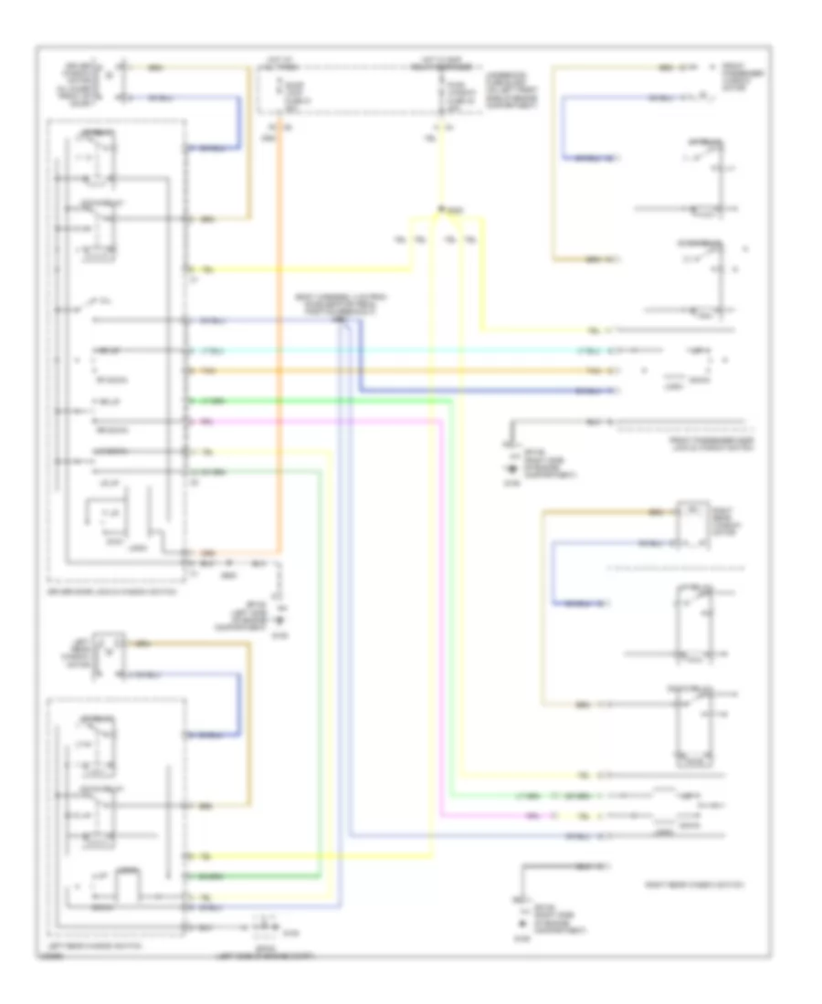
Power Mirrors Wiring Diagram for GMC Canyon 2007
List of elements for Power Mirrors Wiring Diagram for GMC Canyon 2007:
- A29
- Body control module (behind right kick panel)
- Driver outside rearview mirror
- Front passenger outside rearview mirror
- G105 (left side of engine compt)
- Horiz
- Hot at all times
- Left
- Nca
- Off
- Outside rearview mirror switch
- Right
- S500
- Splice pack sp105
- Turn/haz fr fuse 37 15a
- Underhood fuse block (on left front side of engine compt)
- Vert
POWER SEATS
Driver Heated Seat Wiring Diagram for GMC Canyon 2007
List of elements for Driver Heated Seat Wiring Diagram for GMC Canyon 2007:
- (driver heater element harness)
- A/c fuse 5 10a
- A26
- A5 c6
- B nca
- Body control module (behind right kick panel)
- C nca
- Driver heated seat module
- Driver lumbar adjuster/ heater switch
- Driver seat back heater element
- Driver seat cushion heater element
- E nca
- E9 c7
- Element harness) (driver heater s315
- F10 c7
- G106 (right side of engine compt)
- Gnd
- High
- High/low status ind bulb
- Hot at all times
- Htd/seat fuse 18 20a
- Ign 3 hvac relay
- Ign 3 voltage
- Low
- Nca
- Pnk
- Red
- S300
- S301
- S306
- S320
- S321 (driver heater element harness)
- S322
- Underhood fuse block (on left front side of engine compt)
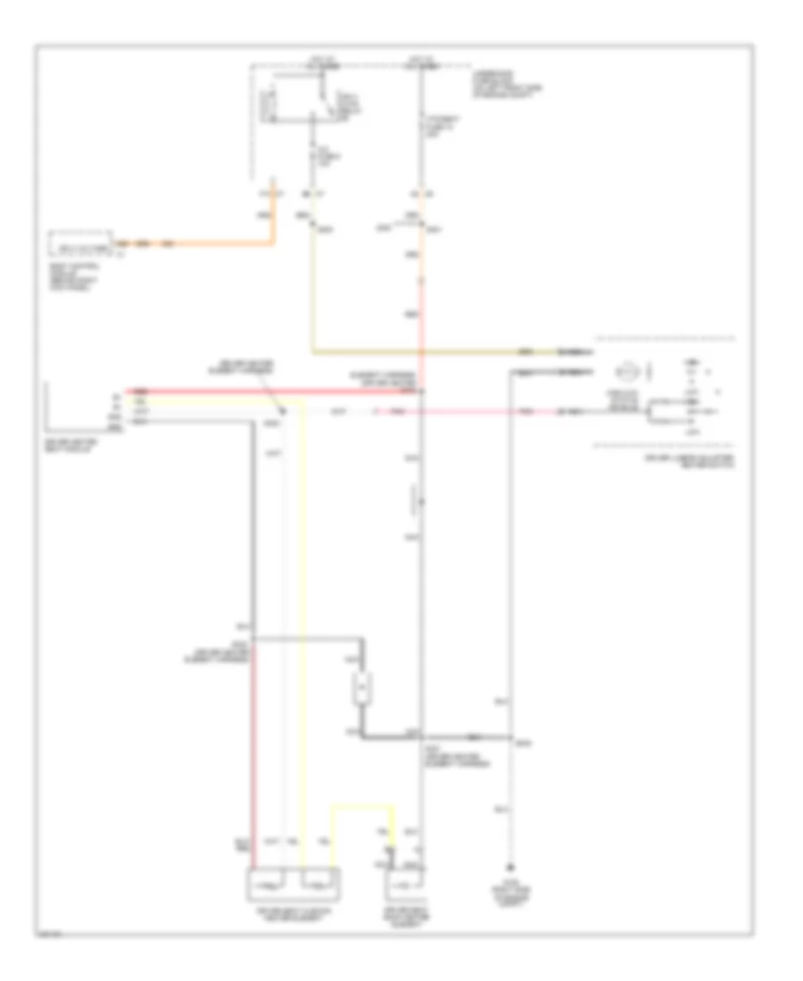
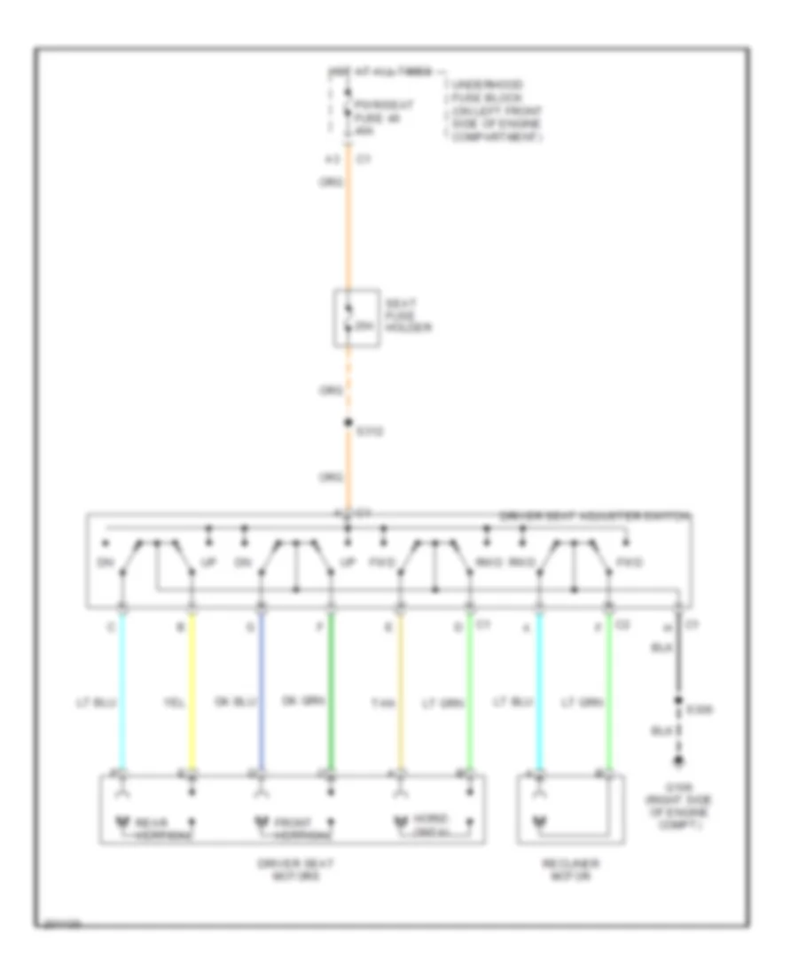
Driver Power Seat Wiring Diagram for GMC Canyon 2007
List of elements for Driver Power Seat Wiring Diagram for GMC Canyon 2007:
- 20a
- Driver seat adjuster switch
- Driver seat motors
- Front vertical
- Fwd
- G106 (right side of engine compt)
- Hot at all times
- M horiz- ontal
- Pwr/seat fuse 46 40a
- Rear vertical
- Recliner motor
- Rwd
- S306
- S312
- Seat fuse holder
- Tan
- Underhood fuse block (on left front side of engine compartment)
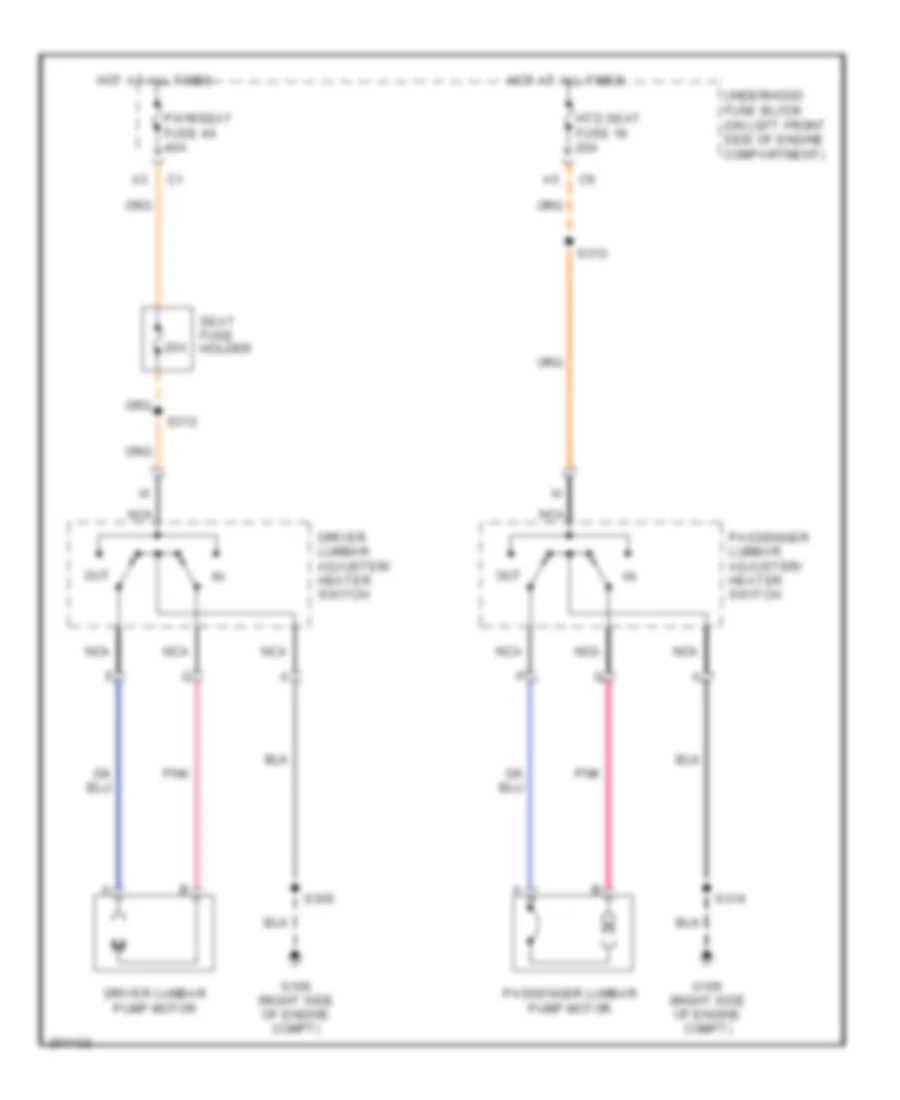
Lumbar Wiring Diagram for GMC Canyon 2007
List of elements for Lumbar Wiring Diagram for GMC Canyon 2007:
- 20a
- Driver lumbar adjuster/ heater switch
- Driver lumbar pump motor
- G106 (right side of engine compt)
- Hot at all times
- Htd seat fuse 18 20a
- Nca
- Out
- Passenger lumbar adjuster/ heater switch
- Passenger lumbar pump motor
- Pnk
- Pwr/seat fuse 46 40a
- S306
- S312
- S313
- S314
- Seat fuse holder
- Underhood fuse block (on left front side of engine compartment)
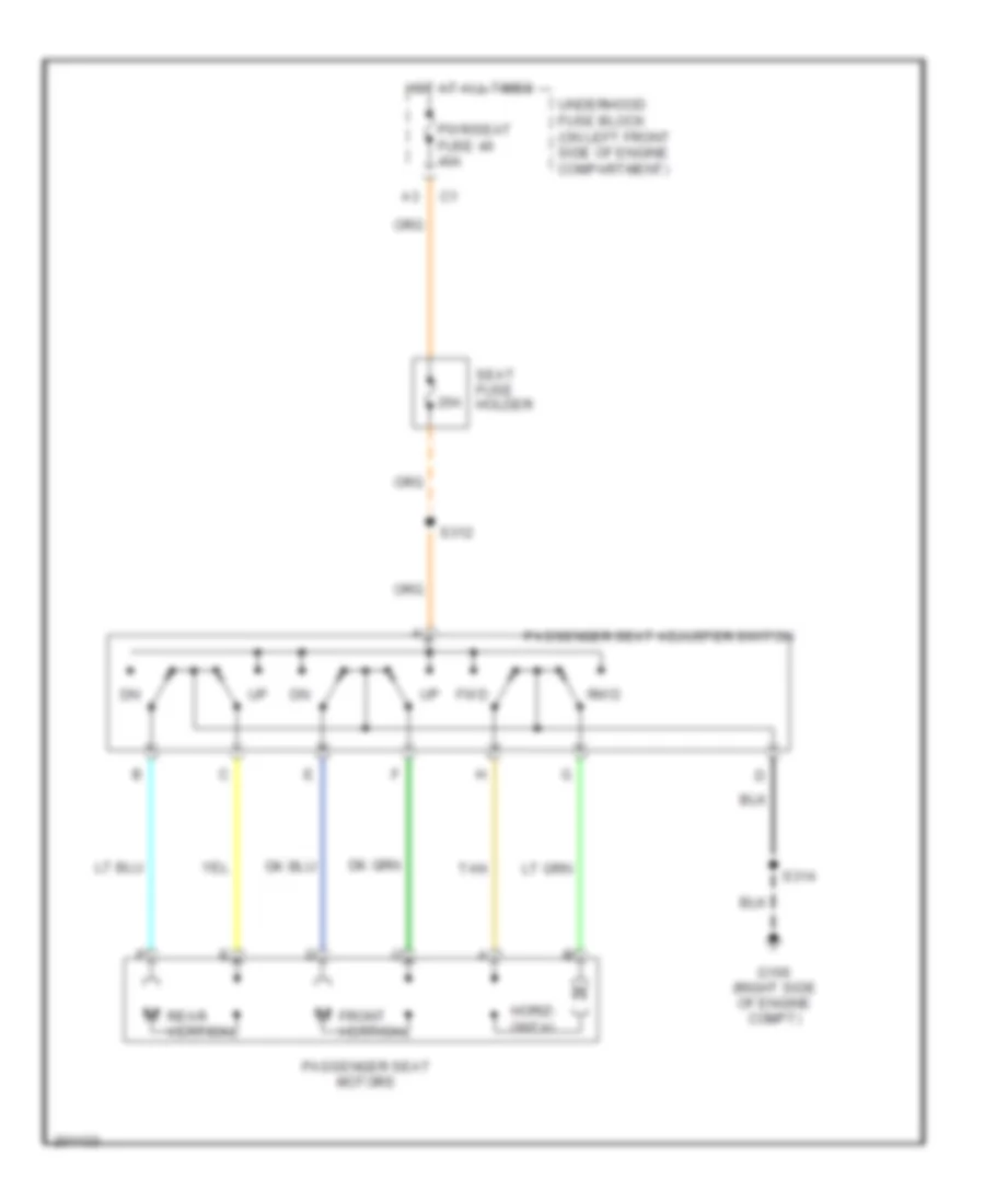
Passenger Power Seat Wiring Diagram for GMC Canyon 2007
List of elements for Passenger Power Seat Wiring Diagram for GMC Canyon 2007:
- 20a
- Front vertical
- Fwd
- G106 (right side of engine compt)
- Horiz- ontal
- Hot at all times
- Passenger seat adjuster switch
- Passenger seat motors
- Pwr/seat fuse 46 40a
- Rear vertical
- Rwd
- S312
- S314
- Seat fuse holder
- Tan
- Underhood fuse block (on left front side of engine compartment)
Passenger"s Heated Seat Wiring Diagram for GMC Canyon 2007
List of elements for Passenger"s Heated Seat Wiring Diagram for GMC Canyon 2007:
- (passenger heater element harness)
- (passenger heater element harness) s319
- A/c fuse 5 10a
- A26
- A5 c6
- B nca
- Body control module (behind right kick panel)
- C nca
- D nca
- E nca
- E9 c7
- F10 c7
- G106 (right side of engine compt)
- Gnd
- High
- High/low status ind bulb
- Hot at all times
- Htd/seat fuse 18 20a
- Ign 3
- Ign 3 hvac relay
- Ign 3 voltage
- Logic
- Low
- Nca
- Passenger heated seat module
- Passenger lumbar adjuster/ heater switch
- Passenger seat back heater element
- Passenger seat cushion heater element
- Pnk
- Red
- Rt seat belt sw
- S300
- S313
- S314
- S316
- S317 (passenger heater element harness)
- S318
- Underhood fuse block (on left front side of engine compt)
POWER TOP/SUNROOF
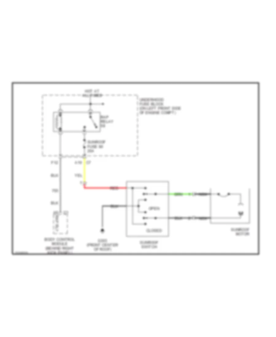
Power Top/Sunroof Wiring Diagram for GMC Canyon 2007
List of elements for Power Top/Sunroof Wiring Diagram for GMC Canyon 2007:
- A10
- A6 rap rly
- Body control module (behind right kick panel)
- Closed
- F12
- G303 (front center of roof)
- Hot at all times
- Nca
- Open
- Rap relay
- Red
- Sunroof fuse 80 20a
- Sunroof motor
- Sunroof switch
- Underhood fuse block (on left front side of engine compt)
POWER WINDOWS
Power Windows Wiring Diagram, 2 Door for GMC Canyon 2007
List of elements for Power Windows Wiring Diagram, 2 Door for GMC Canyon 2007:
- (not used)
- C6 f5
- Door lock fuse 21 20a
- Down
- Down relay
- Driver door lock & window switch
- Driver window motor (in lower front of door)
- Front passenger door lock & window switch
- Front passenger window motor (in lower front of door)
- G105
- G106
- Hot at all times
- Hot w/ rap relay energized
- Logic
- Pwr/ window fuse 42 30a
- Rf down
- Rf up
- S500
- Sp105 (left side of engine compt)
- Sp106 (right side of engine compt)
- Tan
- Underhood fuse block (on left front side of engine compartment)
- Up relay
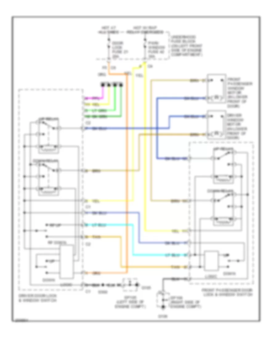
Power Windows Wiring Diagram, 4 Door for GMC Canyon 2007
List of elements for Power Windows Wiring Diagram, 4 Door for GMC Canyon 2007:
- (body harness, 4 cm from accelerator pedal position breakout) s307
- C4 a
- C6 f5
- Door lock fuse 21 20a
- Down
- Down relay
- Driver door lock & window switch
- Driver window motor (in lower front of door)
- Dwn
- Front passenger door lock & window switch
- Front passenger window motor
- G105
- G106
- Hot at all times
- Hot w/ rap relay energized
- Left rear window motor
- Left rear window switch
- Logic
- Lr down
- Lr up
- Pwr/ window fuse 42 30a
- Rf down
- Rf up
- Right rear window motor
- Right rear window switch
- Rr down
- Rr up
- S302
- S500
- Sp105 (left side of engine compartment)
- Sp105 (left side of engine compt)
- Sp106 (right side of engine compartment)
- Tan
- Underhood fuse block (on left front side of engine compartment)
- Up relay
- W/l
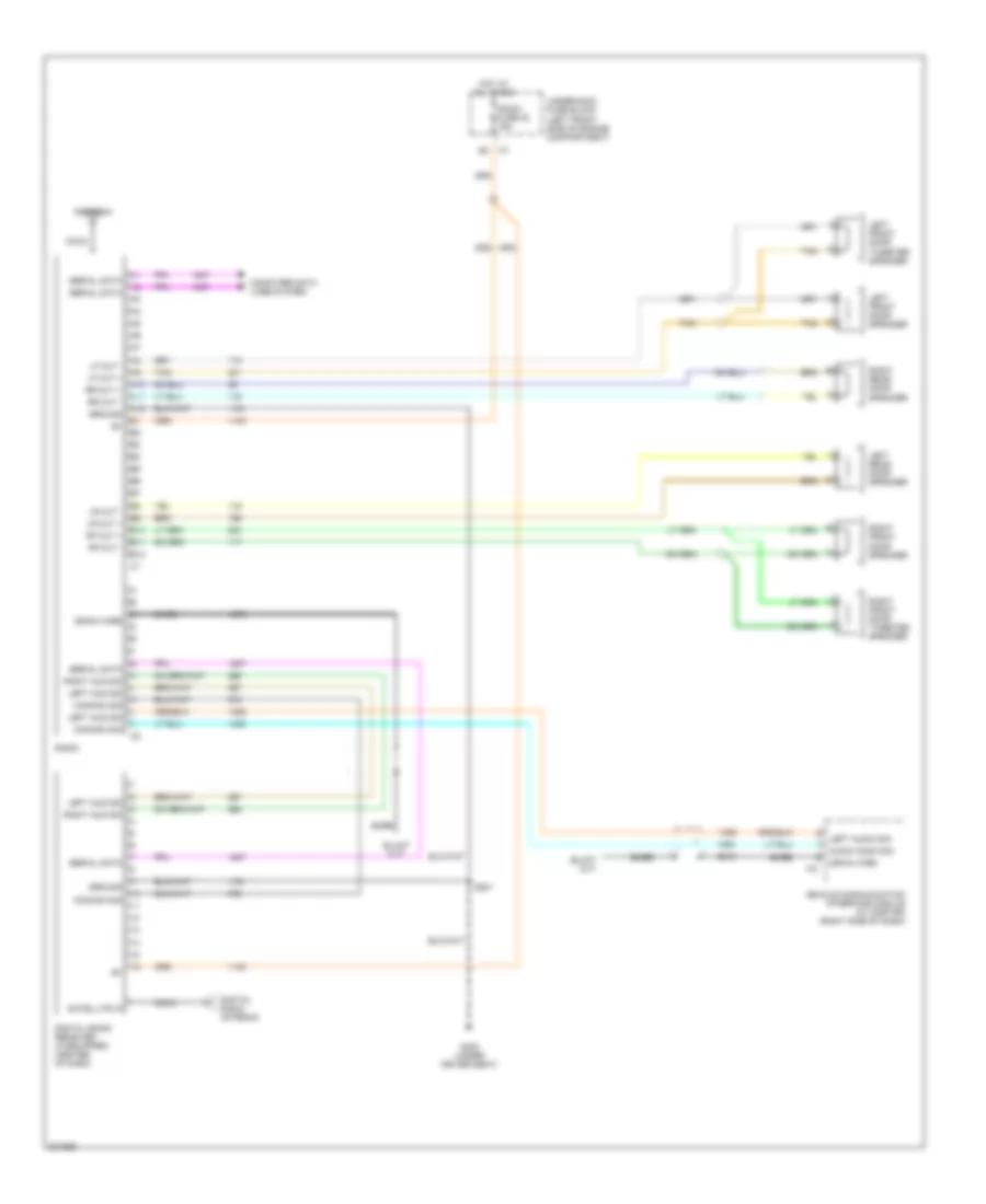
RADIO
Radio Wiring Diagram for GMC Canyon 2007
List of elements for Radio Wiring Diagram for GMC Canyon 2007:
- A10
- A11
- A12
- Antenna
- Audio comm sig
- B10
- B11
- B12
- Bare
- Coax
- Common sig
- Computer data lines system
- Digital radio antenna
- Digital radio receiver (if equipped) (center of dash)
- Drain wire
- G300 (under driver seat)
- Ground
- Hot at all times
- Left aud sig
- Left audio sig
- Left front door speaker
- Left front door tweeter speaker
- Left rear door speaker
- Lf out +
- Lf out -
- Lr out +
- Lr out -
- Radio
- Radio fuse 32 15a
- Rf out +
- Rf out -
- Right aud sig
- Right front door speaker
- Right front door tweeter speaker
- Right rear door speaker
- Rr out +
- Rr out -
- S201
- Satellite in
- Serial data
- Tan
- Underhood fuse block (left front side of engine compartment)
- Vehicle communication interface module (w/ onstar) (right side of dash)
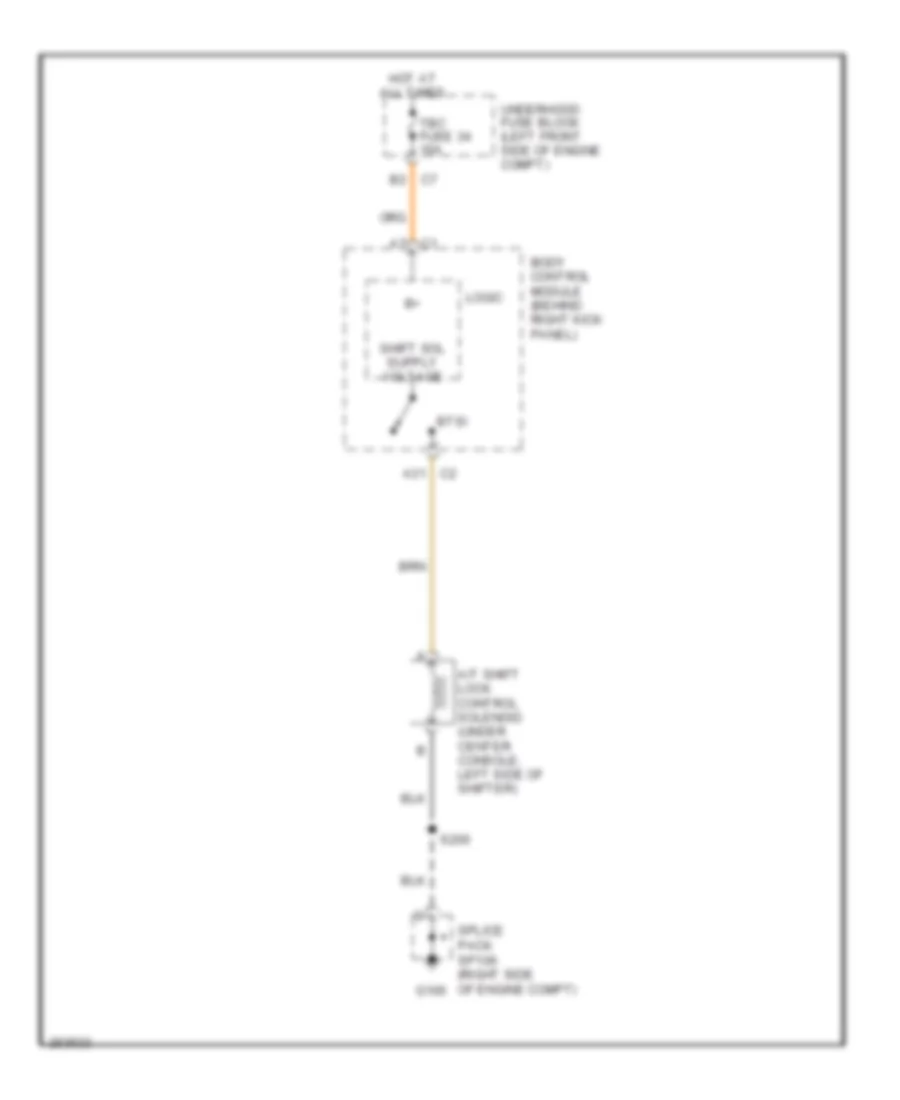
SHIFT INTERLOCK
Shift Interlock Wiring Diagram for GMC Canyon 2007
List of elements for Shift Interlock Wiring Diagram for GMC Canyon 2007:
- A/t shift lock control solenoid (under center console, left side of shifter)
- A31 c2
- B2 c7
- Body control module (behind right kick panel)
- Btsi
- C1 a7
- G106
- Hot at all times
- Logic
- S200
- Splice pack sp106 (right side of engine compt)
- Tbc fuse 34 10a
- Underhood fuse block (left front side of engine compt)
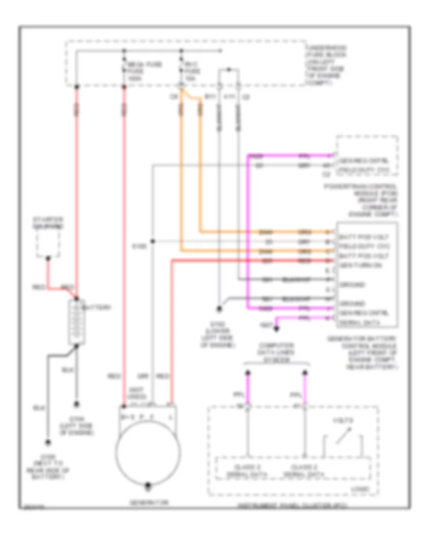
STARTING/CHARGING
Charging Wiring Diagram for GMC Canyon 2007
List of elements for Charging Wiring Diagram for GMC Canyon 2007:
- (not used)
- A11 c2
- B+ s
- B11
- Batt pos volt
- Battery
- Class 2 serial data
- Computer data lines system
- Field duty cyc
- G100 (next to rear side of battery)
- G102 (lower left side of engine)
- G104 (left side of engine)
- Gen reg cntrl
- Gen turn on
- Generator
- Generator battery control module (left front of engine compt, near battery)
- Ground
- Instrument panel cluster (ipc)
- Logic
- Mega fuse fuse 100a
- Powertrain control module (pcm) (right rear corner of engine compt)
- Red
- Rvc fuse 10a
- S105
- Serial data
- Starter solenoid
- Underhood fuse block (on left front side of engine compt)
- Volts
Starting Wiring Diagram, A/T for GMC Canyon 2007
List of elements for Starting Wiring Diagram, A/T for GMC Canyon 2007:
- Acc
- Battery
- Body control module (bcm) (behind right kick panel)
- C1 b6
- C2 b8
- C2 d2
- C2 e2
- C6 f3
- C7 c3
- C7 d1
- G100 (next to rear side of battery)
- G104 (left side of engine)
- G105
- Ign fuse 23 15a
- Ign trans d fuse 10 10a
- Ignition switch
- Off
- Park/neutral position (pnp) switch (lower left side of transmission)
- Pnk
- Pnp start switch sig
- Power distribution system
- Powertrain control module (pcm) (right rear corner of engine compartment)
- Red
- Run
- Run/crank relay 61
- Sp105 (left side of engine compt)
- Start
- Start fuse 43 30a
- Start relay 62
- Starter enable relay ctrl
- Starter solenoid
- Underhood fuse block (on left front side of engine compartment)
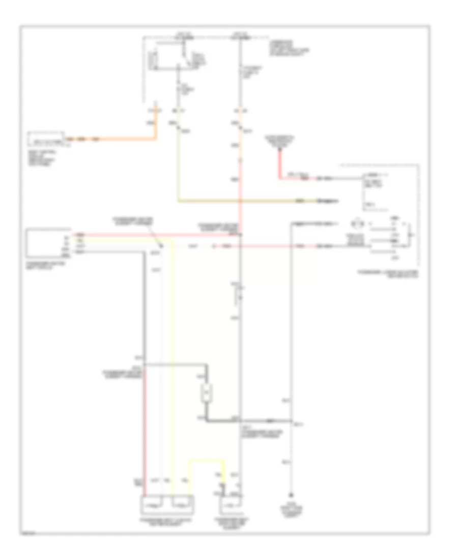
Starting Wiring Diagram, M/T for GMC Canyon 2007
List of elements for Starting Wiring Diagram, M/T for GMC Canyon 2007:
- (not used)
- Acc
- Battery
- Body control module (bcm) (behind right kick panel)
- C1 b6
- C2 b8
- C2 d2
- C2 e2
- C6 f3
- C7 c3
- C7 d1
- C7 e6
- Clutch start switch (top of clutch pedal assembly)
- Clutch start switch sig
- G100 (next to rear side of battery)
- G104 (left side of engine)
- G105
- Ign fuse 23 15a
- Ign trans d fuse 10 10a
- Ignition switch
- Off
- Pnk
- Powertrain control module (pcm) (right rear corner of engine compartment)
- Red
- Run
- Run/crank relay 61
- Sp105 (left side of engine compt)
- Start
- Start fuse 43 30a
- Start relay 62
- Starter enable relay ctrl
- Starter solenoid
- Underhood fuse block (on left front side of engine compartment)
SUPPLEMENTAL RESTRAINTS
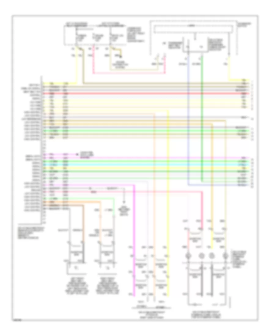
Supplemental Restraints Wiring Diagram (1 of 2) for GMC Canyon 2007
List of elements for Supplemental Restraints Wiring Diagram (1 of 2) for GMC Canyon 2007:
- Accessory switch
- Airbag fuse 10a
- Computer data lines system
- Control
- Cruise fuse 10a
- Disbl sw signal
- G302 (between front seats)
- Ground
- High control
- Hot w/ run/crank relay energized
- Hot with park lamp relay energized
- Ignition 1
- Inflatable restraint i/p module (right side of dash)
- Inflatable restraint passenger airbag on/off indicator
- Inflatable restraint sensing & diagnostic module (sdm) (beneath center console)
- Inflatable restraint steering wheel module (top of steering wheel)
- Inflatable restraint steering wheel module coil (steering wheel)
- Left front seat belt pretensioner (extended cap: in left rear door; regular/crew cab: in left "b" pillar)
- Logic
- Low control
- Low reference
- Nca
- Passenger seat belt indicator
- Pnk
- Power distribution system
- Red
- Right front seat belt pretensioner (extended cap: in right rear door; regular/crew cab: in right "b" pillar)
- Rr pk lp2 fuse 10a
- S324
- Seat belt sw
- Serial data
- Shorting bar
- Signal
- Stage 1
- Stage 2
- Tan
- Underhood fuse block (on left front side of engine compartment)
- Voltage
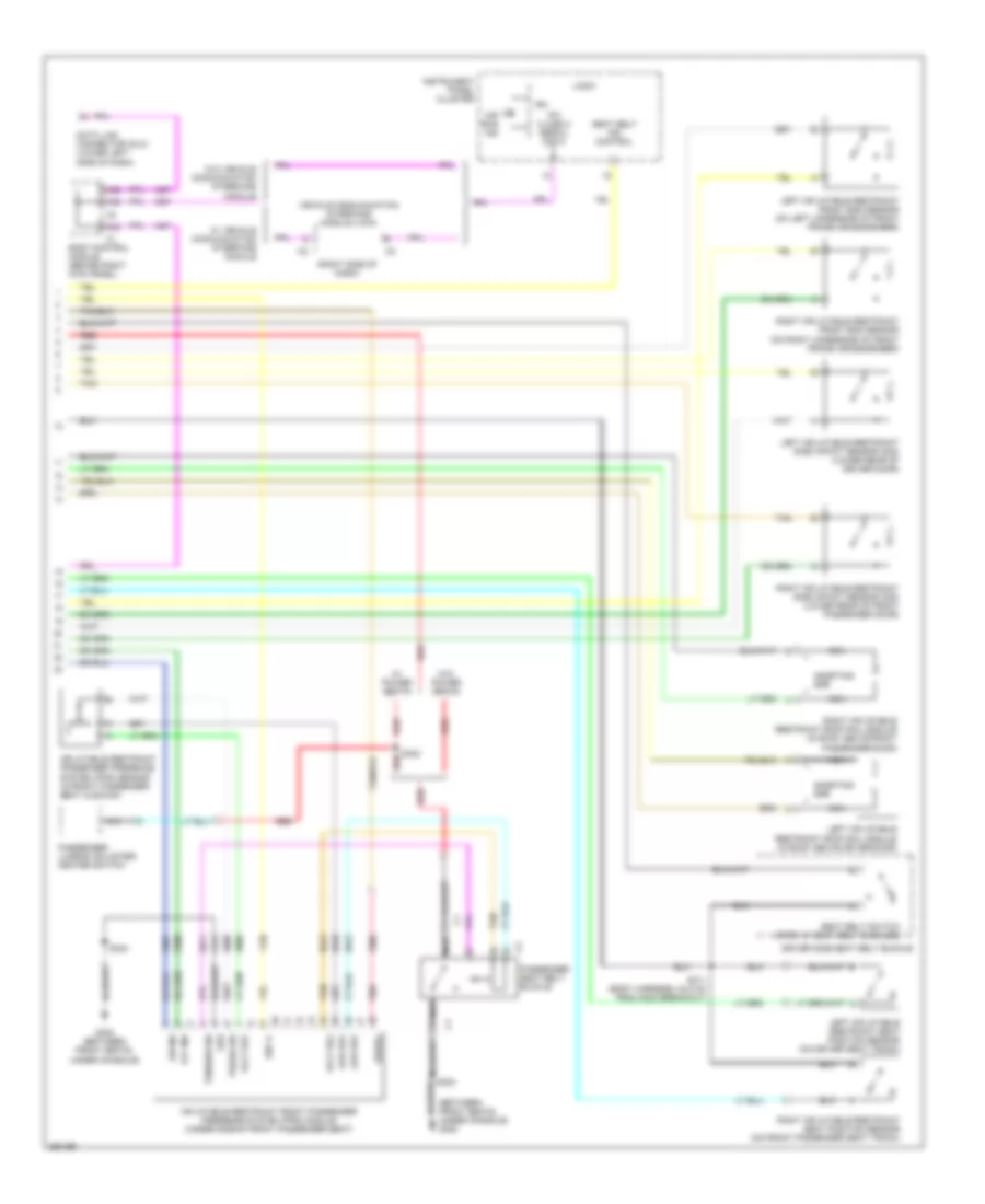
Supplemental Restraints Wiring Diagram (2 of 2) for GMC Canyon 2007
List of elements for Supplemental Restraints Wiring Diagram (2 of 2) for GMC Canyon 2007:
- (between front seats, under console) g302
- (right side of dash)
- A38
- A39
- A42
- Air bag ind
- Body control module (behind right kick panel)
- Data link connector (dlc) (lower left side of dash)
- Driver side seat belt buckle
- G302 (between front seats, under console)
- Grd
- Ign
- Ign 1+
- Inflatable restraint front passenger presence system (pps) module (under side of front passenger seat)
- Inflatable restraint passenger presence system (pps) sensor (in front passenger seat cushion)
- Instrument panel cluster
- Ipc class 2 serial data
- Left inflatable restraint front end sensor (on left underside of front frame crossmember)
- Left inflatable restraint roof rail module (in roof above driver door)
- Left inflatable restraint seat position sensor (on driver seat track)
- Left inflatable restraint side impact sensor (sis) (lower rear of driver door)
- Logic
- Low ref
- Nca
- Nca a
- Off ind
- On ind
- Passenger lumbar adjuster/ heater switch
- Passenger seat belt buckle
- Pnk
- Press sig
- Red
- Right inflatable restraint front end sensor (on right underside of front frame crossmember)
- Right inflatable restraint roof rail module (in roof above front passenger door)
- Right inflatable restraint seat position sensor (on front passenger seat track)
- Right inflatable restraint side impact sensor (sis) (lower rear of front passenger door)
- S311 (body harness, 24.5 cm from g302 breakout)
- S323
- S324
- Seat belt ind control
- Seat belt switch (open w/ seat belt buckled)
- Serial
- Shorting bar
- Tan
- Tension sig
- Vehicle communication interface module (vcim)
- Volt ref
- W/ power seats
- W/ vehicle communication interface module
- W/o power seats
- W/o vehicle communication interface module
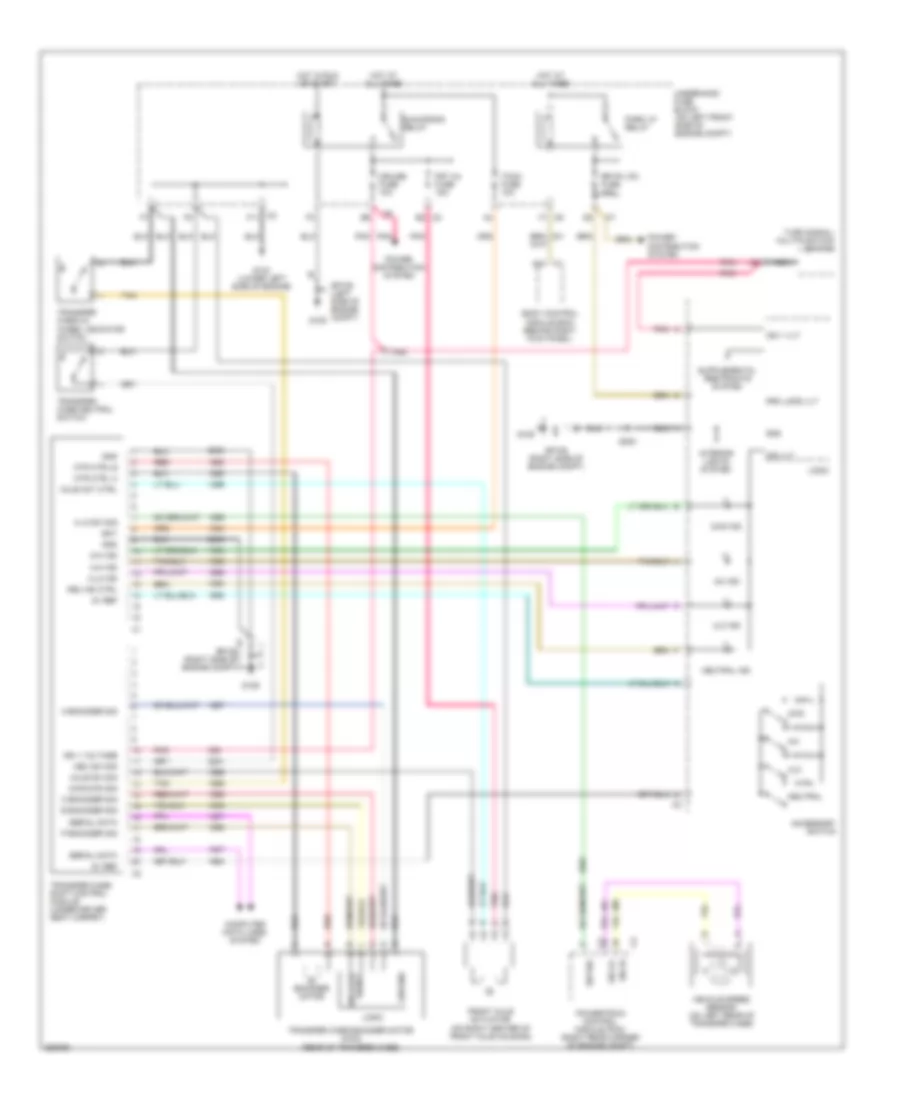
TRANSMISSION
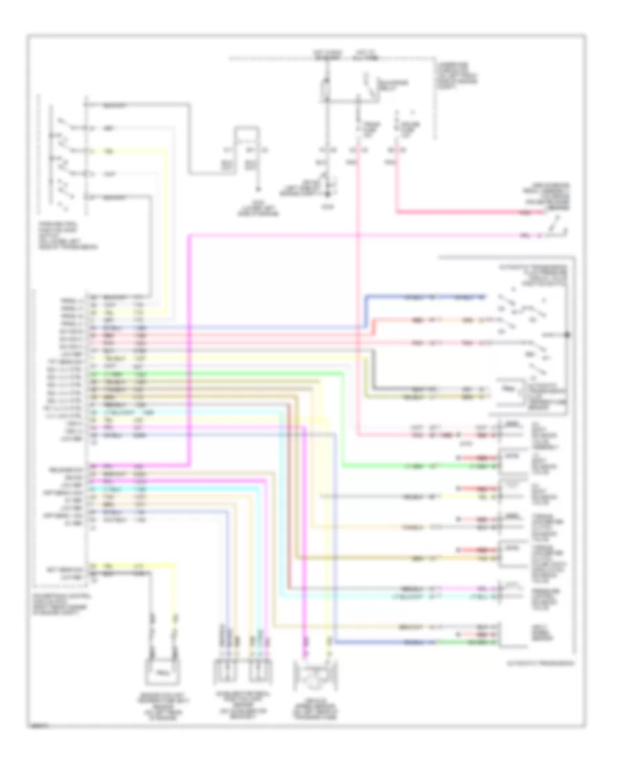
A/T Wiring Diagram for GMC Canyon 2007
List of elements for A/T Wiring Diagram for GMC Canyon 2007:
- (above brake pedal assembly) tcc brake cruise release switch
- 1-2 shift solenoid valve
- 2-3 shift solenoid valve
- 3-2 shift solenoid valve assembly
- 5v ref
- Accelerator pedal position (app) sensor (on accelerator bracket)
- App sens 1 sig
- App sens 2 sig
- Automatic transmission
- Automatic transmission fluid pressure manual valve position switch
- Automatic transmission fluid temperature sensor
- B3 c6
- C11
- C2 b11
- C2 c2
- Cruise fuse 10a
- Ect sens sig
- Engine coolant temperature (ect)
- F3 c6
- G102 (lower left side of engine)
- G105
- Hot at all times
- Hot in run or start
- Input speed sensor
- Iss sig
- Low ref
- Nca
- Park/neutral position (pnp) switch (on lower left side of transmission)
- Pc vlv hi ctrl
- Pnk
- Powertrain control module (pcm) (right rear corner of engine compt)
- Pressure control solenoid valve
- Prndl a
- Prndl b
- Prndl c
- Prndl p
- Red
- Release sig
- Rev
- Run/crank relay
- S133
- Sensor (on left rear of engine)
- Sol vlv ctrl
- Sp105 (left side of engine compt)
- Sw sig a
- Sw sig b
- Sw sig c
- Tan
- Tft sens sig
- Torque converter clutch pulse width modulation solenoid valve
- Torque converter clutch solenoid valve
- Trans fuse 10a
- Underhood fuse block (on left front side of engine compt)
- Vehicle speed sensor (on left rear of transfer case)
- Vlv low ctrl
- Vss hi
- Vss lo
Transfer Case Wiring Diagram for GMC Canyon 2007
List of elements for Transfer Case Wiring Diagram for GMC Canyon 2007:
- 2-hi ind
- 2wd
- 2wd ind
- 2wd/4wd sig
- 4-hi ind
- 4-lo ind
- 4-lo sw sig
- 4hi
- 4hi ind
- 4lo
- 4lo ind
- 5v ref
- A encoder sig
- Accessory switch
- Axle act ctrl
- Axle sw sig
- B encoder sig
- B2 c2
- Bat
- Body control module bcm) (behind right kick panel)
- C encoder sig
- C1 a24
- C2 f11
- C6 f1
- Computer data lines system
- Cruise fuse 10a
- Encoder motor
- Front axle actuator (on right center of front axle housing)
- Frt ax fuse 15a
- G103 (lower left side of engine)
- G105
- G106
- Gnd
- Ground
- Hot at all times
- Hot in run or start
- Ign 1 vlt
- Ign 1 voltage
- Ind vlt
- Interior lights system
- Logic
- Mtr ctrl a
- Mtr ctrl b
- Nca
- Neu ind ctrl
- Neu sw sig
- Neutral
- Neutral ind
- P encoder sig
- Park lp relay
- Pnk
- Power distribution system
- Powertrain control module (pcm) (right rear corner of engine compt)
- Prk lmps vlt
- Red
- Rr pk lp2 fuse 10a
- Run/crank relay
- S200
- Serial data
- Sig hi
- Sig lo
- Signal encoder
- Sp105 (left side of engine compt)
- Sp106 (right side of engine compt)
- Sw sig
- Tan
- Tccm fuse 10a
- Transfer case 2/4 wheel indicator switch
- Transfer case encoder motor (4wd) (rear of transfer case)
- Transfer case neutral switch
- Transfer case shift control module (under driver seat carpet)
- Turn signal/ multifunction switch
- Underhood fuse block (on left front side of engine compt)
- Vehicle speed sensor (on left rear of transfer case)
WARNING SYSTEMS
Warning Systems Wiring Diagram for GMC Canyon 2007
List of elements for Warning Systems Wiring Diagram for GMC Canyon 2007:
- (body harness, 24.5 cm from g302 breakout) s311
- A10
- A14
- A32
- A38
- A39
- A42
- A44
- Auto
- Body control module (bcm) (behind right kick panel)
- C7 b2
- Chime
- Class 2 serial data
- Computer data lines system
- Driver door jamb switch
- Driver seat belt switch (open w/ seat belt buckled)
- G300 (under driver seat)
- G301 (under front passenger seat)
- Headlamp & panel dimmer switch
- Hot at all times
- Ign trans d fuse 10 10a
- Ignition switch
- Inflatable restraint sensing & diagnostic module (sdm) (below passenger's seat)
- Instrument panel cluster (ipc)
- Key-in switch
- Left rear door jamb switch (crew cab)
- Left seat belt sw
- Left turn ind
- Lf dr ajar sw sig
- Logic
- Low ref
- Lr dr ajar sw sig
- Lr turn sig lmps pwr
- Off
- Off/run/crank volt
- Park
- Passenger door jamb switch
- Pk lmp sw sig
- Rf dr ajar sw sig
- Right rear door jamb switch (crew cab)
- Right turn ind
- Rr dr ajar sw sig
- Rr turn sig lmps pwr
- S303
- S304
- Seat belt ind
- Tbc fuse 34 10a
- Underhood fuse block (on left front side of engine compt)
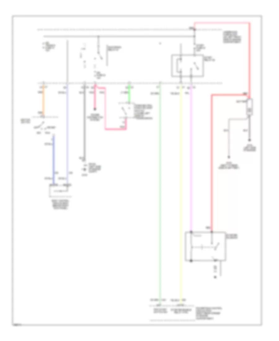
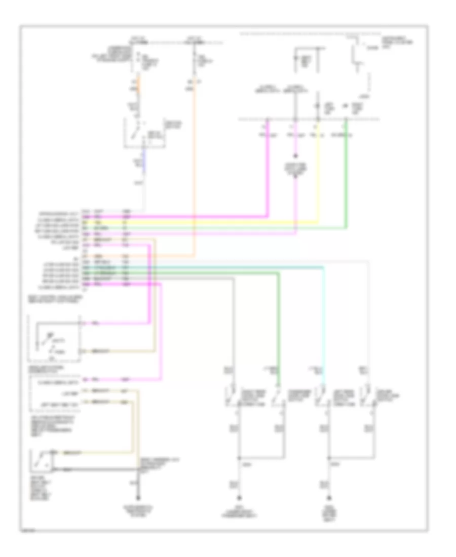
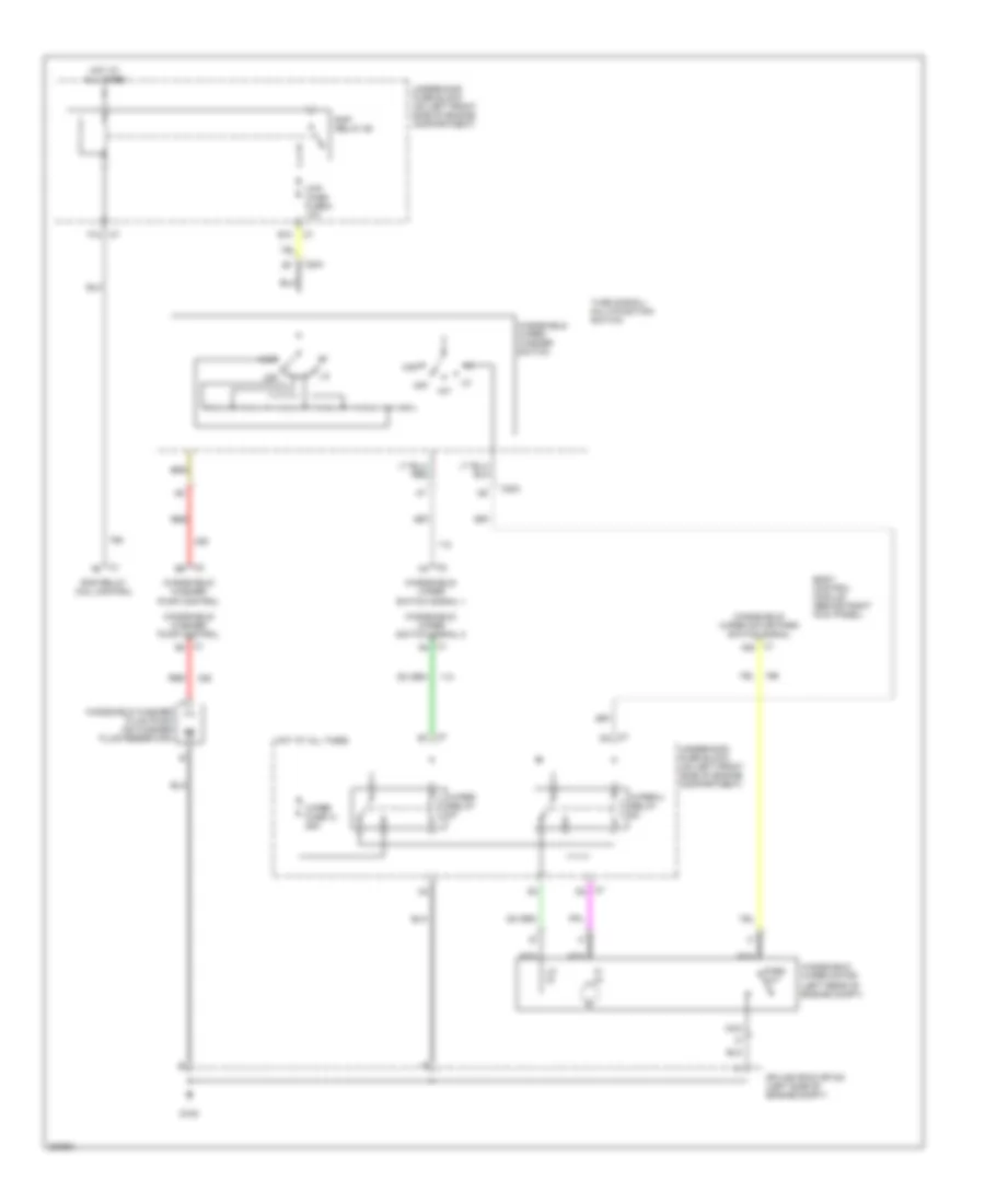
WIPER/WASHER
Wiper/Washer Wiring Diagram for GMC Canyon 2007
List of elements for Wiper/Washer Wiring Diagram for GMC Canyon 2007:
- A20
- B10
- Body control module (behind right kick panel)
- C204
- F12
- G105
- Hi in
- Hot at all times
- Int
- Lo in
- Mist
- Nca
- Off
- Park out
- Rap relay 58
- Rap relay coil control
- Red
- Splice pack sp105 (left side of engine compt)
- Turn signal/ multifunction switch
- Underhood fuse block (on left front side of engine compartment)
- Windshield washer fluid pump (on washer fluid reservoir)
- Windshield wiper motor (left rear of engine compt)
- Windshield wiper/ washer switch
- Windshield/ washer pump control
- Windshield/ wiper motor park switch signal
- Windshield/ wiper switch signal 1
- Windshield/ wiper switch signal 2
- Wip/ wash fuse 8 10a
- Wiper 2 relay
- Wiper fuse 14 25a
- Wiper relay

 Čeština
 Dansk
Dansk Deutsch
 Ελληνικά
 English
 English
 Español
 Français
 Français
 עברית
עברית Hrvatski
 Magyar
 Italiano
 日本語
日本語 한국어
한국어 Nederlands
 Polski
 Português
 Português
 Română
 Русский
 Slovenčina
 Slovenščina
 Svenska
 Türkçe
 中文 (中国)