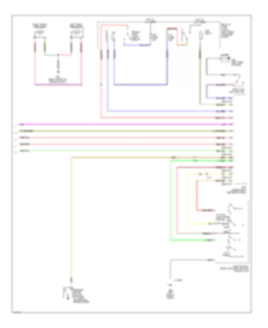
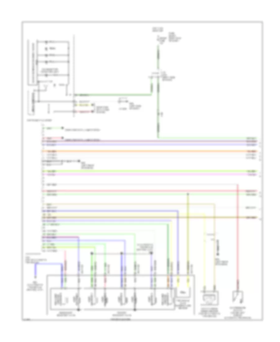
AIR CONDITIONING
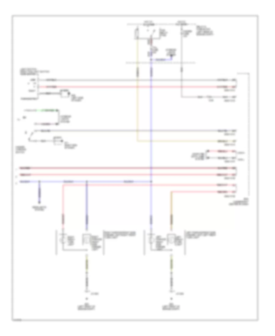
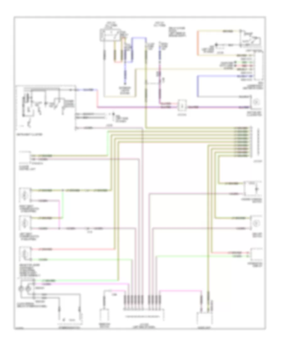
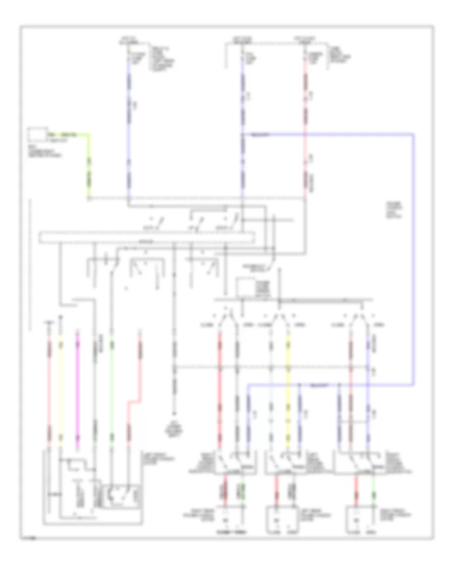
Automatic A/C Wiring Diagram (1 of 2) for Mazda 5 Touring 2013
 https://portal-diagnostov.com/license.html
Automotive Electricians Portal FZCO
Automotive Electricians Portal FZCO
https://portal-diagnostov.com/license.html
https://portal-diagnostov.com/license.html
Automotive Electricians Portal FZCO
Automotive Electricians Portal FZCO
List of elements for Automatic A/C Wiring Diagram (1 of 2) for Mazda 5 Touring 2013:
- (right side of a/c unit) air intake actuator
- 0740-201a
- 0740-201b
- A/c fuse 10a
- A/c mag fuse 10a
- A/c relay
- Blower relay 1
- Blower relay 2
- C-02
- C-05
- C-66
- Climate control unit
- Computer data lines system
- Front blower motor (center of a/c unit)
- Front power mos fet (lower right side of a/c unit)
- Fuse block (right end of dash)
- G02
- G09 (left side of dash)
- Heater 1 fuse 40a
- Heater 2 fuse 30a
- Heater 3 fuse 30a
- Hot at all times
- Hot in on or start
- Interior lights system
- J/c c-44
- J/c g02
- J/c g09
- Magnetic clutch (on a/c compressor)
- Rear blower motor (under center of dash)
- Rear fan switch
- Rear vent actuator (lower front of a/c unit)
- Red
- Relay & fuse block (left rear of engine compt)
- Room fuse 15a
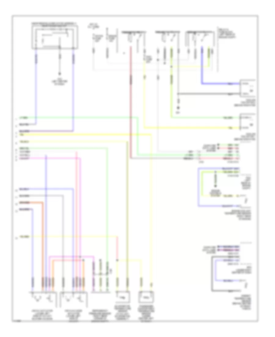
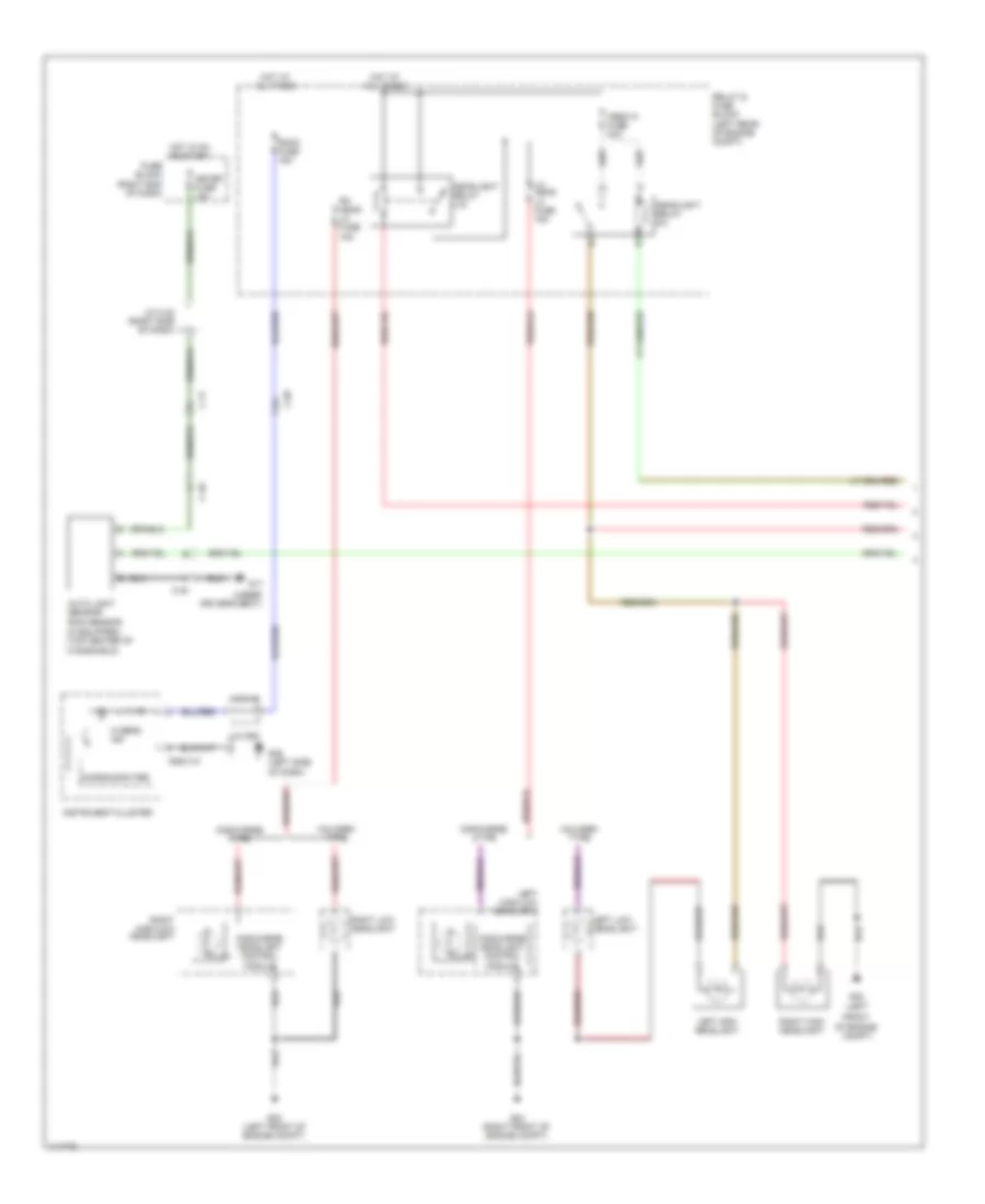
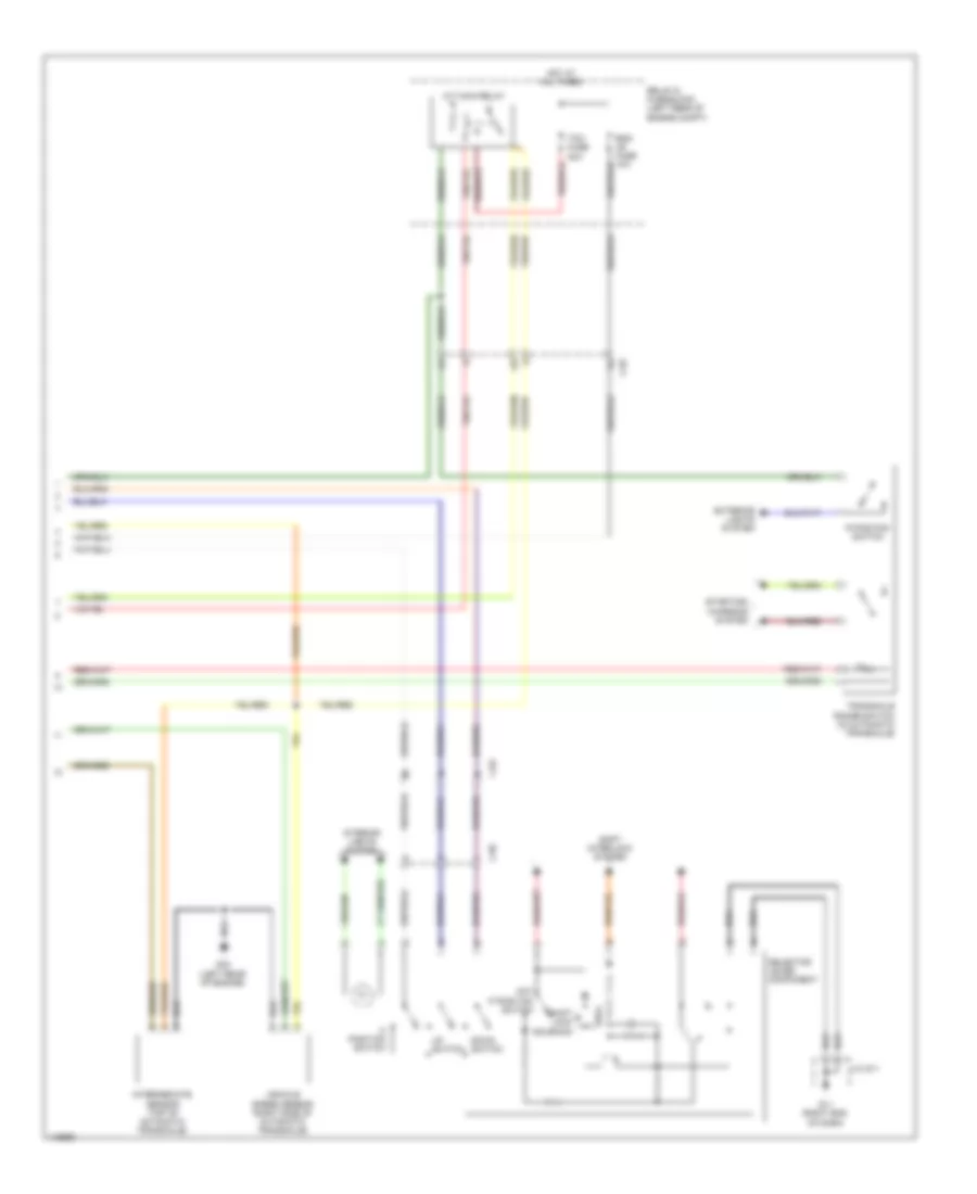
Automatic A/C Wiring Diagram (2 of 2) for Mazda 5 Touring 2013
List of elements for Automatic A/C Wiring Diagram (2 of 2) for Mazda 5 Touring 2013:
- (near rear blower motor assembly) rear power mos fet
- 0140-101a
- 0140-101b
- 0940-101a
- 0940-101f
- 1ai
- 1am
- 2ah
- 2av
- Ad fan fuse 30a
- Air flow mode actuator (lower left side of a/c unit)
- Air mix actuator (lower left side of a/c unit blower housing)
- Ambient temperature sensor (behind center of front fascia)
- Bcm (under right center of dash)
- C-02
- C-05
- Computer data lines system
- Cooling fan motor 1 (behind radiator)
- Cooling fan motor 2 (behind radiator)
- Cooling fan relay 1
- Cooling fan relay 2
- Cooling fan relay 3
- Eng+b fuse 10a
- Engine controls system
- Engine coolant temperature sensor (right rear of engine)
- Evaporator temperature sensor (in a/c unit evaporator assembly)
- Fan1 fuse 30a
- G01
- G12 (left center of dash)
- Hot at all times
- Passenger compartment temperature sensor (under center left of dash)
- Pcm (left rear of engine compt)
- Red
- Refrigerant pressure sensor (right rear corner of engine compt)
- Relay & fuse block (left rear of engine compt)
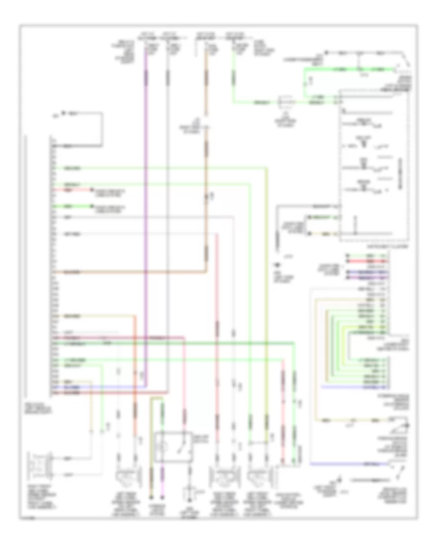
ANTI-LOCK BRAKES
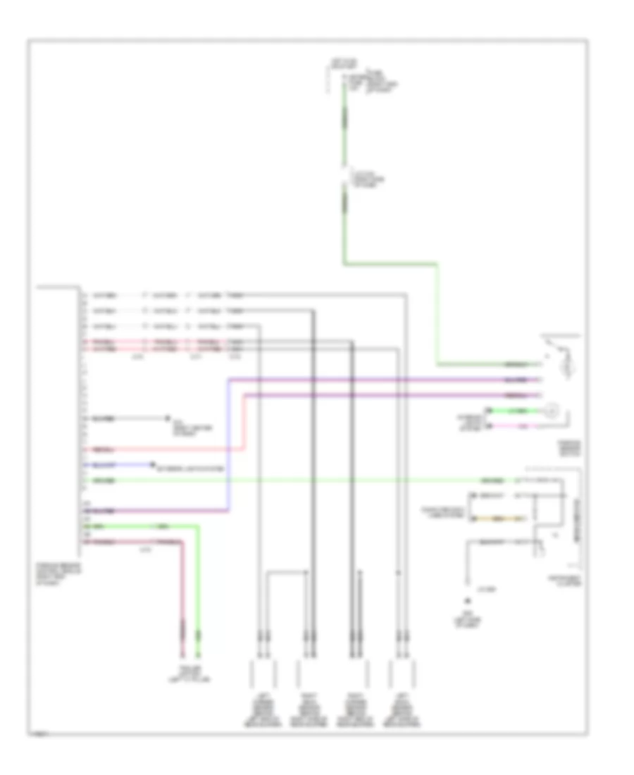
Anti-lock Brakes Wiring Diagram for Mazda 5 Touring 2013
List of elements for Anti-lock Brakes Wiring Diagram for Mazda 5 Touring 2013:
- 0810-101b
- 0940-101a
- 0940-101c
- 0940-101f
- Abs ind
- Abs p fuse 40a
- Abs v fuse 20a
- Bcm (under right center of dash)
- Brake fluid level sensor (in brake fluid reservoir)
- Brake ind
- Brake switch (top of brake pedal bracket)
- C-04
- C-05
- C-10
- C-11
- C-17
- C-18
- C-34
- C-35
- C-37
- Compt)
- Computer data lines system
- Dsc hu/cm (left rear of engine compt)
- Dsc ind
- Dsc off ind
- Dsc off switch
- Fuse block (right end of dash)
- G01
- G02 (left front of engine j/c 2
- G09 (left side of dash)
- G14 (under passenger's seat)
- Hot at all times
- Hot in on or start
- Instrument cluster
- Interior lights system
- J/c 9
- J/c c-42 (right side of dash)
- J/c c-43 (right end of dash)
- Left front abs wheel speed sensor (on left front wheel hub assembly)
- Left rear abs wheel speed sensor (on left rear wheel hub assembly)
- Meter fuse 10a
- Microcomputer
- Parking brake switch (at base of parking brake lever)
- Red
- Relay & fuse block (left rear of engine compt)
- Right front abs wheel speed sensor (on right front wheel hub assembly)
- Right rear abs wheel speed sensor (on right rear wheel hub assembly)
- Sas control module (under center console)
- Sas fuse 10a
- Steering angle sensor (on steering column)
ANTI-THEFT
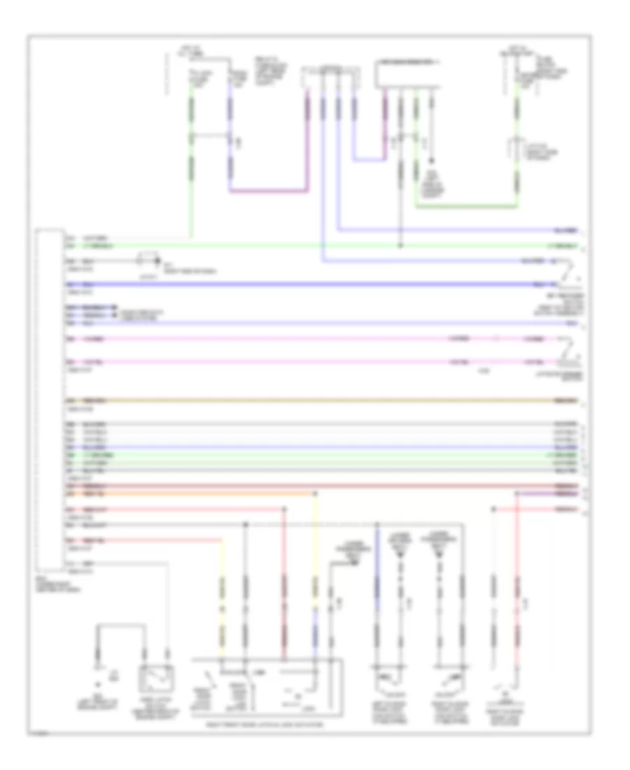
Forced Entry Wiring Diagram (1 of 2) for Mazda 5 Touring 2013
List of elements for Forced Entry Wiring Diagram (1 of 2) for Mazda 5 Touring 2013:
- (if equipped)
- (under driver's seat) g17
- (under passenger's seat) g14
- 0940-101a
- 0940-101c
- 0940-101d
- 0940-101e
- 0940-101f
- Bcm (under right center of dash)
- C-05
- C-17
- C-18
- C-20
- C-30
- C-31
- C-32
- Computer data lines system
- D lock fuse 20a
- Front door latch switch
- Front door lock- link switch
- Fuse block (right end of dash)
- G02 (left front of engine compt)
- G11 (right end of dash)
- G16 (left side of luggage compt)
- Hood latch switch (center front of engine compt)
- Hot at all times
- Hot in on or start
- J/c c-42 (right side of dash)
- J/c c-44
- J/c g02
- J/c g11
- Key reminder switch (part of ignition switch assembly)
- Keyless receiver
- Left sliding door lock-
- Liftgate opener switch
- Link switch
- Lock
- Meter fuse 10a
- Relay & fuse block (left rear of engine compt)
- Right front door latch & lock actuator
- Right sliding door lock actuator
- Right sliding door lock-
- Room fuse 15a
- Unlock
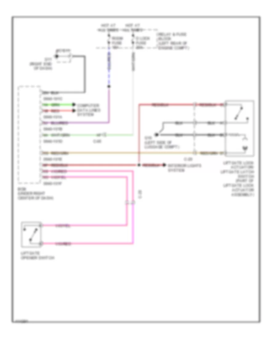
Forced Entry Wiring Diagram (2 of 2) for Mazda 5 Touring 2013
List of elements for Forced Entry Wiring Diagram (2 of 2) for Mazda 5 Touring 2013:
- (left "c" pillar)
- (under
- C-20
- C-29
- C-30
- C-32
- Computer data lines system
- Door ind
- Driver's seat)
- Front door latch switch
- Front door lock- link switch
- G09 (left side of dash)
- G14 (under passenger's seat)
- G16 (left side of
- G17
- G17 (under driver's seat)
- Instrument cluster
- J/c g09
- Key cylinder switch
- Left door lock switch
- Left front door latch & lock actuator
- Left sliding door lock actuator
- Left sliding door switch
- Liftgate lock actuator (bottom center of liftgate)
- Lock
- Luggage compt)
- Microcomputer
- Right door lock switch
- Right sliding door switch (right "c" pillar)
- Security ind
- Unlock
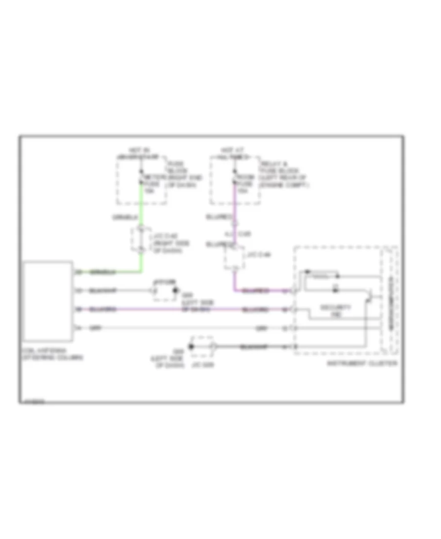
Immobilizer Wiring Diagram for Mazda 5 Touring 2013
List of elements for Immobilizer Wiring Diagram for Mazda 5 Touring 2013:
- (right side of dash)
- Aj c-05
- Coil antenna (steering column)
- Fuse block (right end of dash)
- G09 (left side of dash)
- Hot at all times
- Hot in on or start
- Instrument cluster
- J/c c-42
- J/c c-44
- J/c g09
- Meter fuse 10a
- Microcomputer
- Relay & fuse block (left rear of engine compt)
- Room fuse 15a
- Security ind
BODY CONTROL MODULES
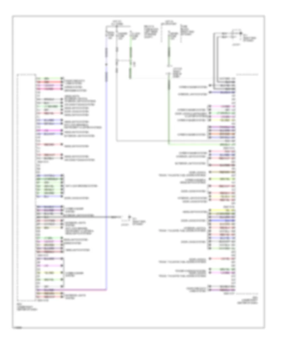
Body Control Modules Wiring Diagram for Mazda 5 Touring 2013
List of elements for Body Control Modules Wiring Diagram for Mazda 5 Touring 2013:
- 0940-101a
- 0940-101b
- 0940-101c
- 0940-101d
- 0940-101e
- 0940-101f
- Air conditioning system
- Anti-lock brakes & instrument cluster systems
- Anti-lock brakes system
- Anti-lock brakes, instrument cluster & headlights systems
- Bcm (under right center of dash)
- C-05
- Computer data lines system
- D lock fuse 20a
- Defogger system
- Door locks & instrument cluster systems
- Door locks & trunk, tailgate, fuel doors systems
- Door locks system
- Exterior lights system
- Fuse block (right end of dash)
- G11 (right end of dash)
- Hazard fuse 10a
- Headlights system
- Headlights, exterior lights & interior lights systems
- Horns system
- Hot at all times
- Hot in on or start
- Interior lights & trunk, tailgate, fuel doors systems
- Interior lights system
- J/c c-42 (right side of dash)
- J/c g11
- Meter fuse 10a
- Pnk
- Power windows system door locks & trunk, tailgate, fuel doors systems
- Red
- Relay & fuse block (left rear of engine compt)
- Room fuse 15a
- Wiper/washer & headlights systems
- Wiper/washer system
COMPUTER DATA LINES
Computer Data Lines Wiring Diagram for Mazda 5 Touring 2013
List of elements for Computer Data Lines Wiring Diagram for Mazda 5 Touring 2013:
- 0140-101a
- 0614-101b
- 0740-201a
- 0810-101a
- 0920-201a
- 0940-101a
- 0940-101f
- 1ai
- 1am
- Audio unit
- Bcm (under right center of dash)
- C-02
- C-05
- C-18
- Climate control unit
- Data link connector (dlc) 2 (under lower left side of dash)
- Dsc hu/cm (left rear of engine compt)
- Ehpas control module (right front of engine compt)
- G09 (left side of dash)
- G23 (left rear of engine)
- Hot at all times
- Hs can-h
- Hs can-l
- Information display
- Instrument cluster
- J/c 09
- J/c c-44
- J/c c-45 (right center of dash)
- J/c c-47 (behind instrument cluster)
- Ms can-h
- Ms can-l
- Pcm (left rear of engine compt)
- Pnk
- Red
- Relay & fuse block (left rear of engine compt)
- Room fuse 15a
- Sas control module (under center console)
- Sirius satellite radio unit (if equipped) (right end of dash)
- Tcm (a/t) (top of automatic transaxle)
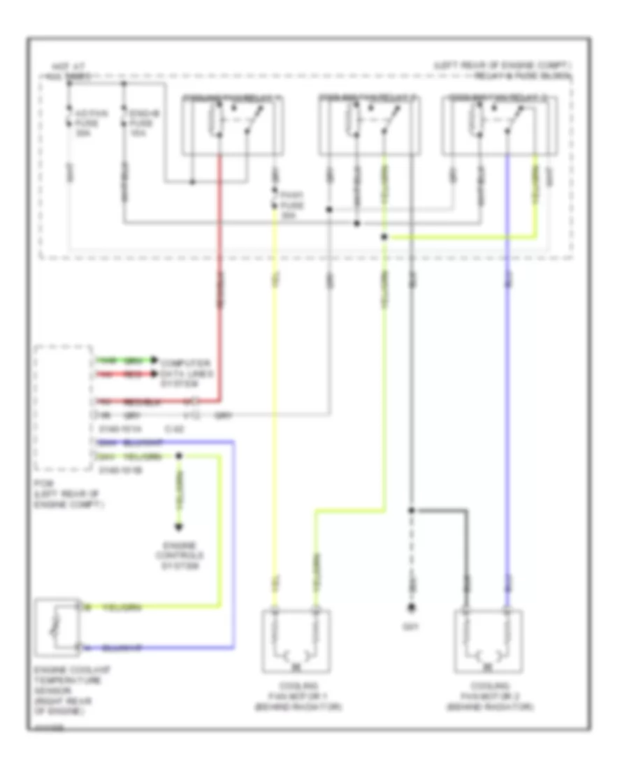
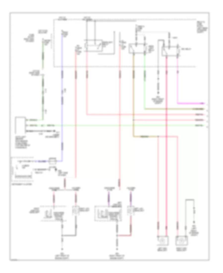
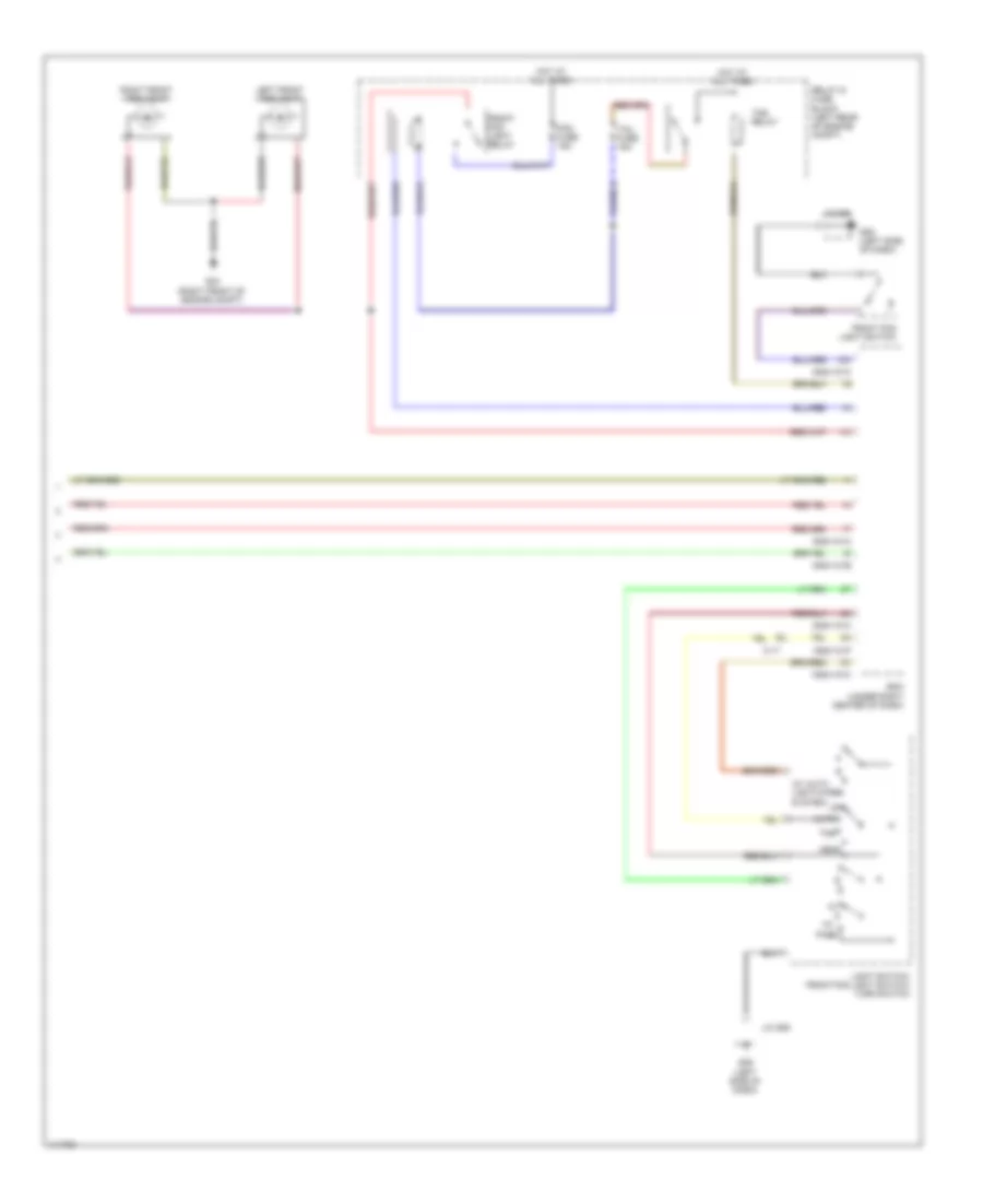
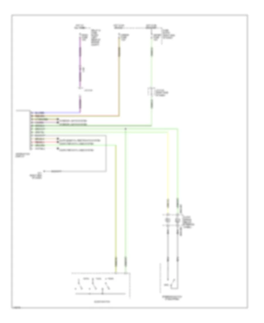
COOLING FAN
Cooling Fan Wiring Diagram for Mazda 5 Touring 2013
List of elements for Cooling Fan Wiring Diagram for Mazda 5 Touring 2013:
- (left rear of engine compt) relay & fuse block
- 0140-101a
- 0140-101b
- 1ai
- 1am
- 2ah
- 2av
- Ad fan fuse 30a
- C-02
- Computer data lines system
- Cooling fan motor 1 (behind radiator)
- Cooling fan motor 2 (behind radiator)
- Cooling fan relay 1
- Cooling fan relay 2
- Cooling fan relay 3
- Eng+b fuse 10a
- Engine controls system
- Engine coolant temperature sensor (right rear of engine)
- Fan1 fuse 30a
- G01
- Hot at all times
- Pcm (left rear of engine compt)
- Red
CRUISE CONTROL
Cruise Control Wiring Diagram for Mazda 5 Touring 2013
List of elements for Cruise Control Wiring Diagram for Mazda 5 Touring 2013:
- (left side of manual transaxle)
- (under passenger's seat) g14
- (w/ cruise control switch)
- 0140-101a
- 0140-101b
- 0922-201
- 0922-202
- 1ab
- 1ae
- 1ai
- 1aj
- 1am
- 1an
- 1ao
- 1ap
- 1aq
- 1av
- 1bc
- 1bd
- 2ak
- 2al
- 2an
- 2ar
- 2be
- 2bf
- Accelerator pedal position sensor (top of accelerator pedal bracket)
- Brake switch (top of brake pedal bracket)
- C-02
- C-04
- C-05
- C-10
- C-13
- C-69
- Cancel switch
- Clock spring (below steering wheel)
- Clutch pedal position switch (m/t) (top of clutch pedal assembly)
- Computer data lines system
- Cruise (amber) ind
- Cruise off switch
- Cruise on switch
- Eng +b fuse 10a
- G09 (left side of dash)
- G23 (left rear of engine)
- Hot at all times
- Input/turbine speed sensor (top of automatic transaxle)
- Instrument cluster
- J/c c-44
- Microcomputer
- Nca
- Neutral switch (m/t)
- Pcm (left rear of engine compt)
- Pnk
- Red
- Relay & fuse block (left rear of engine compt)
- Resume switch
- Room fuse 15a
- Set(+) switch
- Set(-) switch
- Steering switch
- Stop fuse 10a
- Tcm (top of automatic transaxle)
- Throttle body (left rear of engine)
- Vehicle speed sensor (right side of automatic transaxle)
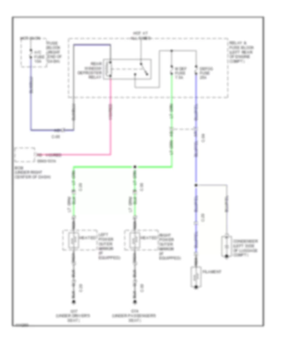
DEFOGGERS
Defoggers Wiring Diagram for Mazda 5 Touring 2013
List of elements for Defoggers Wiring Diagram for Mazda 5 Touring 2013:
- 0940-101a
- A/c fuse 10a
- All times
- Bcm (under right center of dash)
- C-04
- C-05
- C-20
- C-29
- C-30
- Condenser (left side of luggage compt)
- Defog fuse 25a
- Filament
- Fuse block (right end of dash)
- G14 (under passenger's seat)
- G17 (under driver's seat)
- Heated
- Hot at
- Hot in on
- Left power outer mirror (if equipped)
- M def fuse 7.5a
- Nca
- Rear window defroster relay
- Relay & fuse block (left rear of engine compt)
- Right power outer mirror (if equipped)
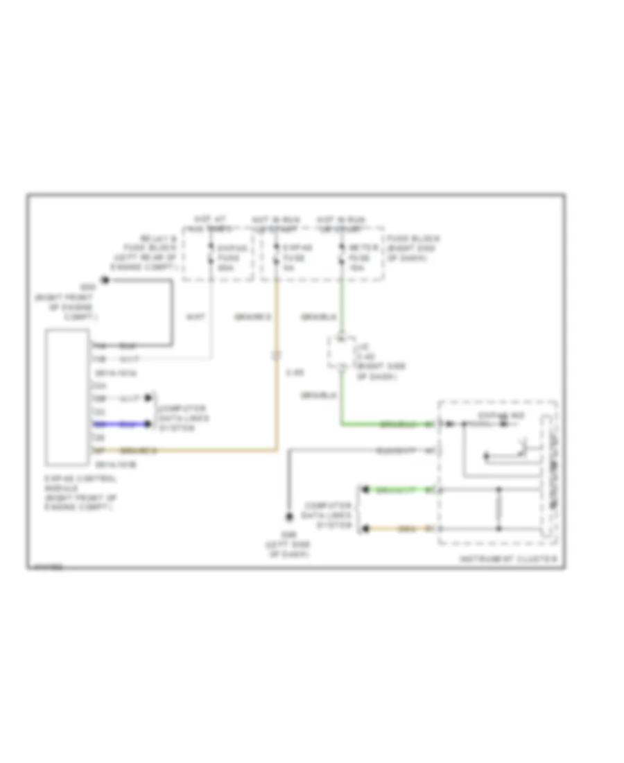
ELECTRONIC POWER STEERING
Electronic Power Steering Wiring Diagram for Mazda 5 Touring 2013
List of elements for Electronic Power Steering Wiring Diagram for Mazda 5 Touring 2013:
- (right front
- 0614-101a
- 0614-101b
- C-05
- Compt)
- Computer data lines system
- Ehpas control module (right front of engine compt)
- Ehpas fuse 5a
- Ehpas fuse 80a
- Ehpas ind
- Fuse block (right end of dash)
- G05
- G09 (left side of dash)
- Hot at all times
- Hot in run or start
- Instrument cluster
- J/c c-42 (right side of dash)
- Meter fuse 10a
- Micro computer
- Of engine
- Relay & fuse block (left rear of engine compt)
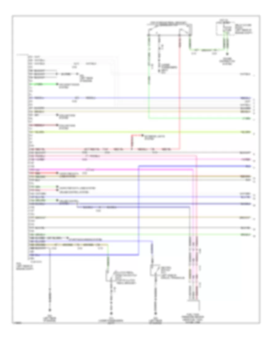
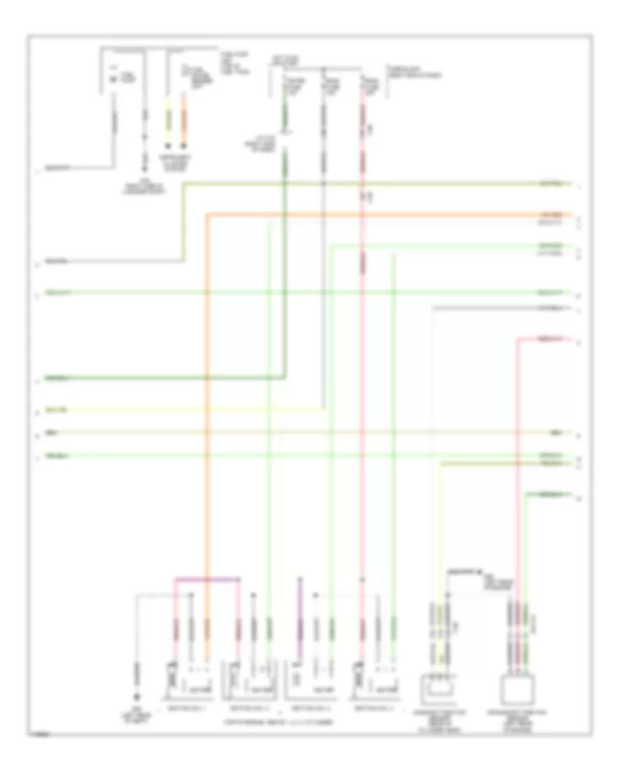
ENGINE PERFORMANCE
2.5L
2.5L, Engine Performance Wiring Diagram (1 of 4) for Mazda 5 Touring 2013
List of elements for 2.5L, Engine Performance Wiring Diagram (1 of 4) for Mazda 5 Touring 2013:
- (top of brake pedal bracket) brake switch
- (under passenger's seat) g14
- 0140-101a
- 1aa
- 1ab
- 1ac
- 1ad
- 1ae
- 1af
- 1ag
- 1ah
- 1ai
- 1aj
- 1ak
- 1al
- 1am
- 1an
- 1ao
- 1ap
- 1aq
- 1ar
- 1as
- 1at
- 1au
- 1av
- 1aw
- 1ax
- 1ay
- 1az
- 1ba
- 1bb
- 1bc
- 1bd
- 1be
- 1bf
- 1bg
- 1bh
- Air conditioning system
- C-02
- C-04
- C-10
- C-11
- C-12
- C-18
- Clutch pedal position switch (m/t) (top of clutch pedal bracket)
- Computer data lines system
- Cooling fans system
- Cruise control system
- Exterior lights system
- Fuel tank pressure sensor (near fuel tank, in fuel line)
- G14 (under passenger's seat)
- G23 (left rear of engine)
- Hot at all times
- Nca
- Neutral switch (m/t) (left side of manual transaxle)
- Pcm (left rear of engine compt)
- Pnk
- Power distribution system
- Red
- Relay & fuse block (left rear of engine compt)
- Starting/charging system
- Stop fuse 10a
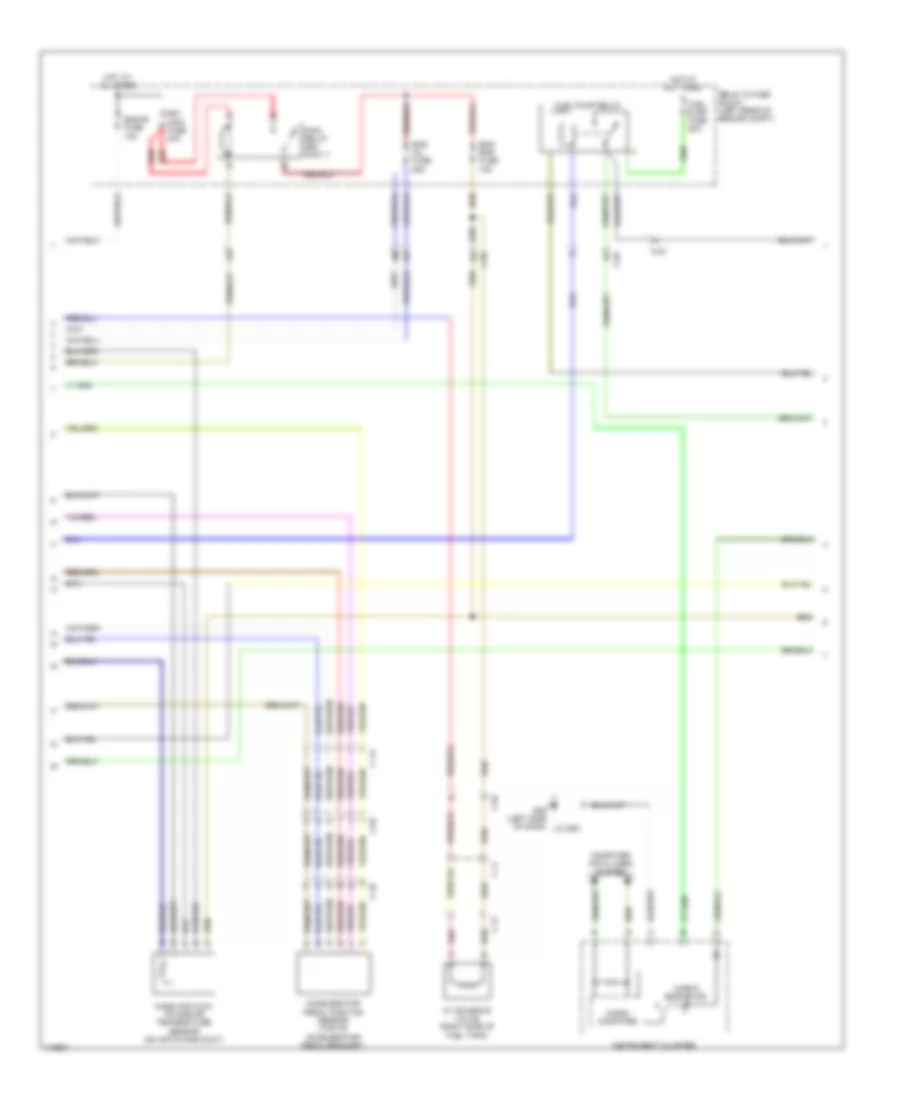
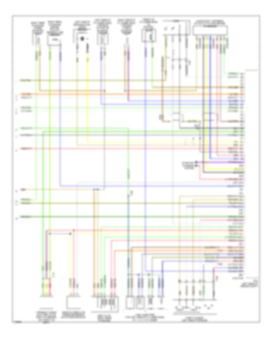
2.5L, Engine Performance Wiring Diagram (2 of 4) for Mazda 5 Touring 2013
List of elements for 2.5L, Engine Performance Wiring Diagram (2 of 4) for Mazda 5 Touring 2013:
- Accelerator pedal position sensor (top of accelerator pedal bracket)
- C-02
- C-04
- C-10
- C-11
- C-12
- C-13
- Check engine ind
- Computer data lines system
- Cv solenoid valve (right side of fuel tank)
- Eg1 main fuse 40a
- Eng bar fuse 15a
- Eng inj fuse 25a
- Eng+b fuse 10a
- Fuel pump fuse 20a
- Fuel pump relay
- G09 (left side of dash)
- Hot at all times
- Instrument cluster
- J/c g09
- Main relay (egi main 1)
- Mass air flow/ intake air temperature sensor (on air intake duct)
- Micro- computer
- Pnk
- Red
- Relay & fuse block (left rear of engine compt)
2.5L, Engine Performance Wiring Diagram (3 of 4) for Mazda 5 Touring 2013
List of elements for 2.5L, Engine Performance Wiring Diagram (3 of 4) for Mazda 5 Touring 2013:
- (top of engine, above 1, 2, 3, 4 cylinder)
- 014-141
- C-02
- C-05
- C-69
- Camshaft position sensor (rear of cylinder head)
- Crankshaft position sensor (left rear of engine)
- Eng2 fuse 15a
- Eng3 fuse 20a
- Fuel gauge sender unit
- Fuel pump
- Fuel pump unit (top of fuel tank)
- Fuse block (right end of dash)
- G15 (right side of luggage compt)
- G29 (left rear of engine)
- G29 (left rear of seat)
- Hot in on or start
- Igniter
- Ignition coil 1
- Ignition coil 2
- Ignition coil 3
- Ignition coil 4
- Instrument cluster system
- J/c c-42 (right side of dash)
- Meter fuse 10a
2.5L, Engine Performance Wiring Diagram (4 of 4) for Mazda 5 Touring 2013
List of elements for 2.5L, Engine Performance Wiring Diagram (4 of 4) for Mazda 5 Touring 2013:
- (front of cylinder head) oil control valve
- (in exhaust, upstream of catalytic converter) a/f sensor
- (left rear of cylinder head) variable intake air solenoid valve
- (left side of engine block) knock sensor
- (right rear of cylinder head) variable tumble solenoid valve
- (right rear of engine) engine coolant temperature sensor
- (right rear of engine) purge solenoid valve
- 0140-101b
- 0140-107a
- 0140-107b
- 2aa
- 2ab
- 2ac
- 2ad
- 2ae
- 2af
- 2ag
- 2ah
- 2ai
- 2aj
- 2ak
- 2al
- 2am
- 2an
- 2ao
- 2ap
- 2aq
- 2ar
- 2as
- 2at
- 2au
- 2av
- 2aw
- 2ax
- 2ay
- 2az
- 2ba
- 2bb
- 2bc
- 2bd
- 2be
- 2bf
- 2bg
- 2bh
- C-02
- C-14
- C-69
- Egr valve (right rear of engine)
- Fuel injectors (top left side of cylinder head, at 1, 2, 3, 4 cylinder)
- Ho2s
- Manifold absolute pressure sensor (on intake manifold)
- Nca
- Pcm (left rear of engine compt)
- Red
- Starting/ charging system
- Throttle body (left rear of engine)
- Variable tumble shutter valve position sensor (on throttle body)
EXTERIOR LIGHTS
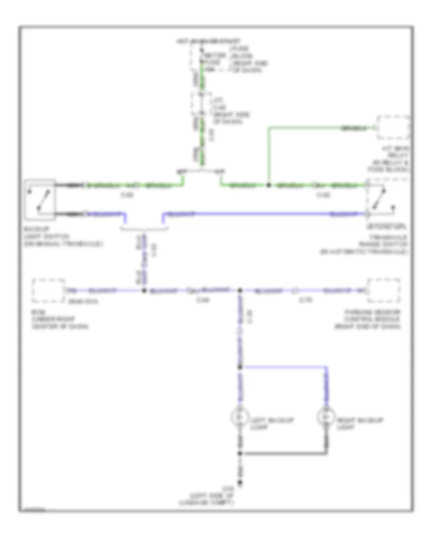
Backup Lamps Wiring Diagram for Mazda 5 Touring 2013
List of elements for Backup Lamps Wiring Diagram for Mazda 5 Touring 2013:
- 0940-101a
- A/t
- A/t main relay (in relay & fuse block)
- Backup light switch (on manual transaxle)
- Bcm (under right center of dash)
- C-02
- C-04
- C-05
- C-20
- C-70
- Fuse block (right end of dash)
- G16 (left side of luggage compt)
- Hot in on or start
- J/c c-42 (right side of dash)
- Left backup light
- M/t
- Meter fuse 10a
- Nca
- Parking sensor control module (right end of dash)
- R position
- Right backup light
- Transaxle range switch (in automatic transaxle)
Exterior Lamps Wiring Diagram (1 of 2) for Mazda 5 Touring 2013
List of elements for Exterior Lamps Wiring Diagram (1 of 2) for Mazda 5 Touring 2013:
- 0140-101a
- 1ab
- Brake switch (top of brake pedal bracket)
- C-02
- C-04
- C-10
- C-17
- C-20
- C-29
- C-30
- Computer data lines system
- Fuse block (right end of dash)
- G09 (left side of dash)
- G14 (under passenger's seat)
- G15 (right side of
- G16 (left side of luggage compt)
- G17 (under driver's seat)
- High-mount brake light
- Hot at all times
- Hot in on or start
- Instrument cluster
- J/c c-42 (right side of dash)
- J/c g09
- Left brake light
- Left front side turn light (if equipped)
- Left license plate light
- Left rear turn light
- Left tail light
- Left tail light/ left brake light/ left rear turn light
- Left turn ind
- Luggage compt)
- Meter fuse 10a
- Microcomputer
- Nca
- Pcm (left rear of engine compt)
- Power distribution system
- Relay & fuse block (left rear of engine compt)
- Right brake light
- Right front side turn light (if equipped)
- Right license plate light
- Right rear turn light
- Right tail light
- Right tail light/ right brake light/ right rear turn light
- Right turn ind
- Selector lever component (a/t) (base of shift lever assembly)
- Stop fuse 10a
Exterior Lamps Wiring Diagram (2 of 2) for Mazda 5 Touring 2013
List of elements for Exterior Lamps Wiring Diagram (2 of 2) for Mazda 5 Touring 2013:
- 0940-101a
- 0940-101b
- 0940-101c
- 0940-101d
- 0940-101e
- 0940-101f
- All times
- Bcm (under right center of dash)
- C-05
- Can-h
- Can-l
- Computer data lines system
- G02 (left front of engine compt)
- G09 (left side of dash)
- G11 (right end of dash)
- Hazard fuse 10a
- Hazard warning switch
- Headlights system
- Hot at
- Hot at all times
- Ill
- Interior lights system
- J/c g02
- J/c g09
- J/c g11
- Left
- Left front turn light
- Left parking/ front side marker light
- Left parking/front side marker light/left front turn light
- Light switch/ front fog light switch/ turn switch
- Relay & fuse block (left rear of engine compt)
- Right
- Right front turn light
- Right parking/ front side marker light
- Right parking/front side marker light/right front turn light
- Tns relay (tns)
- Turn switch
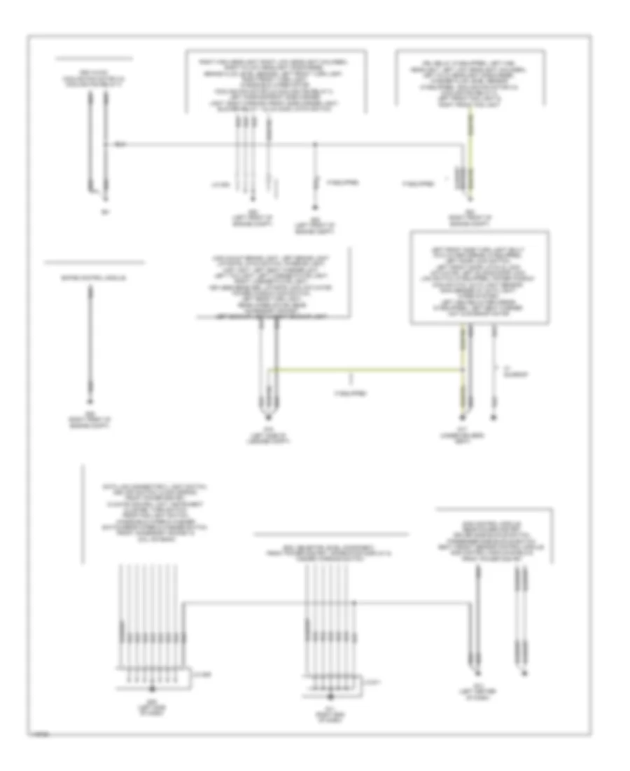
GROUND DISTRIBUTION
Ground Distribution Wiring Diagram (1 of 2) for Mazda 5 Touring 2013
List of elements for Ground Distribution Wiring Diagram (1 of 2) for Mazda 5 Touring 2013:
- Bcm, selector level component, front power mos fet, information display & hazard warning switch
- Data link connector 2, light switch, dsc off switch, clock spring, front power mos fet, climate control unit, instrument cluster, turn switch, front fog light switch, windshield wiper & washer switch/rear wiper & washer switch, front accessory socket & coil antenna
- Drl relay (if equipped), left high headlight, left low headlight (halogen), left hi/lo headlight (discharge), washer fluid level sensor (if equipped), cooling fan motor 2 & cooling fan relay 2, left front fog light & right front fog light
- Dsc hu/cm, cooling fan motor 2 & cooling fan relay 2
- Ehpas control module
- G01
- G02 (left front of engine compt)
- G04 (right front of engine compt)
- G05 (right front of engine compt)
- G09 (left side of dash)
- G11 (right end of dash)
- G12 (left center of dash)
- G16 (left side of luggage compt)
- G17 (under driver's seat)
- If equipped
- J/c g02
- J/c g09
- J/c g11
- Left front side turn light (built into outer mirror) (if equipped), left door lock switch, left front door latch & lock actuator, left sliding door lock link switch (if equipped), power window main switch, auto light sensor/ rain sensor (w/ auto light/ wiper system), left heated outer mirror (if equipped), left seat warmer unit & sunroof motor
- Light, right parking /front side marker light, blower relay 1 & 2 & hood latch switch
- Right high headlight, right low headlight (halogen), right hi/low headlight (discharge), brake fluid level sensor, left front turn light, right front turn light, windshield wiper motor, cooling fan motor 2 & cooling fan relay 2, left parking/front side marker
- Sas control module, rear power mos fet, driver side buckle switch, passenger side buckle switch, seat weight sensor control module, sas control module shield & front power mos fet
- Sunroof
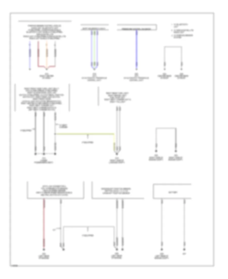
Ground Distribution Wiring Diagram (2 of 2) for Mazda 5 Touring 2013
List of elements for Ground Distribution Wiring Diagram (2 of 2) for Mazda 5 Touring 2013:
- A/t
- Battery
- Crankshaft position sensor, ignition coils 1, 2, 3, 4 & camshaft position sensor
- Data link connector 2, tcm, intermediate sensor, vehicle speed sensor, input/turbine speed sensor shield, neutral switch (m/t) & pcm
- G10 (right center of dash)
- G14 (under passenger's seat)
- G15 (right side of luggage compt)
- G19 (a/t) (in automatic transaxle control unit)
- G20 (a/t) (in automatic transaxle control unit)
- G23 (left rear of engine)
- G29 (left rear of engine)
- G32 (right side of engine compt)
- G33 (right side of engine compt)
- G34 (center rear of roof)
- G35 (center rear of roof)
- G36 (left rear of engine compt)
- G37
- If equipped
- Pressure control solenoid
- Right front side turn light (built into outer mirror) (if equipped), right sliding door lock link switch (if equipped), clutch pedal position switch (m/t), right door lock switch, right front door latch & lock actuator, brake switch, right heated outer mirror (if equipped), right seat warmer unit, right seat warmer switch & left seat warmer switch
- Right rear turn light, right brake light, fuel pump unit, right seat warmer unit & right taillight
- Shift solenoid a, b & c
- System
- Unit
- W/ parking sensor
- W/ seat warmer
- W/ sirius satellite radio unit
HEADLIGHTS
Headlights Wiring Diagram, with DRL (1 of 2) for Mazda 5 Touring 2013
List of elements for Headlights Wiring Diagram, with DRL (1 of 2) for Mazda 5 Touring 2013:
- (if equipped) (top center of windshield)
- (left
- (left front of
- (right front of
- (right front of engine compt)
- (under driver's seat)
- 0922-101
- Auto light sensor/ rain sensor
- C-05
- C-17
- C-40
- Discharge headlight control module
- Discharge type
- Drl relay
- Engine compt)
- Front of engine compt)
- Fuse block (right end of dash)
- G02
- G04
- G09 (left side of dash)
- G17
- Halogen type
- Head hi fuse 20a
- Head- light relay (hi)
- Headlight relay (lo)
- Hi beam ind
- Hot at all times
- Hot in on or start
- Instrument cluster
- J/c c-42 (right side of dash)
- J/c c-44
- J/c g09
- Left high headlight
- Left high/low headlight
- Left low headlight
- Lh head lo fuse 15a
- Meter fuse 15a
- Microcomputer
- Pnk
- Relay & fuse block (left rear of engine compt)
- Rh head lo fuse 15a
- Right high headlight
- Right high/low headlight
- Right low headlight
- Room fuse 15a
Headlights Wiring Diagram, with DRL (2 of 2) for Mazda 5 Touring 2013
List of elements for Headlights Wiring Diagram, with DRL (2 of 2) for Mazda 5 Touring 2013:
- (right front of engine compt)
- 0940-101a
- 0940-101c
- 0940-101e
- 0940-101f
- Auto
- Bcm (under right center of dash)
- C-17
- Fog fuse 15a
- Front fog light relay
- Front fog light switch
- G04
- G09 (left side of dash)
- Head
- Hot at all times
- J/c g09
- Left front fog light
- Light switch/ front fog light switch/ turn switch
- Off
- Parking brake switch (at base of parking brake lever)
- Pass
- Relay & fuse block (left rear of engine compt)
- Right front fog light
- Tail fuse 15a
- Tns
- Tns relay
- W/ auto light/wiper system
Headlights Wiring Diagram, without DRL (1 of 2) for Mazda 5 Touring 2013
List of elements for Headlights Wiring Diagram, without DRL (1 of 2) for Mazda 5 Touring 2013:
- (if equipped) (top center of windshield)
- (left
- (under driver's seat)
- 0922-101
- Auto light sensor/ rain sensor
- C-05
- C-17
- C-40
- Discharge headlight control module
- Discharge type
- Front of engine compt)
- Fuse block (right end of dash)
- G02
- G02 (left front of engine compt)
- G04 (right front of engine compt)
- G09 (left side of dash)
- G17
- Halogen type
- Head hi fuse 20a
- Headlight relay (hi)
- Headlight relay (lo)
- Hi beam ind
- Hot at all times
- Hot in on or start
- Instrument cluster
- J/c c-42 (right side of dash)
- J/c c-44
- J/c g09
- Left high headlight
- Left high/low headlight
- Left low headlight
- Lh head lo fuse 15a
- Meter fuse 15a
- Microcomputer
- Relay & fuse block (left rear of engine compt)
- Rh head lo fuse 15a
- Right high headlight
- Right high/low headlight
- Right low headlight
- Room fuse 15a
Headlights Wiring Diagram, without DRL (2 of 2) for Mazda 5 Touring 2013
List of elements for Headlights Wiring Diagram, without DRL (2 of 2) for Mazda 5 Touring 2013:
- (right front of engine compt)
- (w/ auto light/wiper system)
- 0940-101a
- 0940-101c
- 0940-101e
- 0940-101f
- Auto
- Bcm (under right center of dash)
- C-17
- Fog fuse 15a
- Front fog light relay
- Front fog light switch
- G04
- G09 (left side of dash)
- Head
- Hot at all times
- J/c g09
- Left front fog light
- Light switch/ front fog light switch/ turn switch
- Off
- Pass
- Relay & fuse block (left rear of engine compt)
- Right front fog light
- Tail fuse 15a
- Tns
- Tns relay
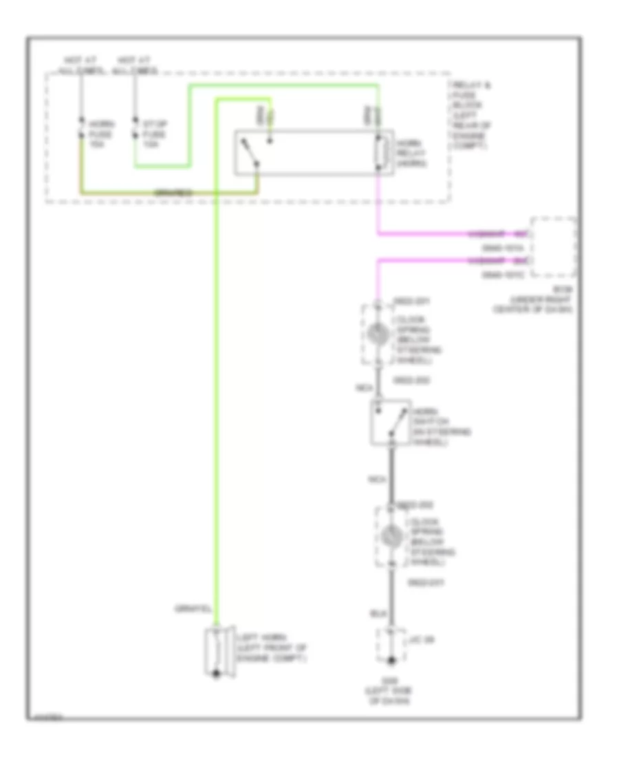
HORN
Horn Wiring Diagram for Mazda 5 Touring 2013
List of elements for Horn Wiring Diagram for Mazda 5 Touring 2013:
- 0922-201
- 0922-202
- 0940-101a
- 0940-101c
- Bcm (under right center of dash)
- Clock spring (below steering wheel)
- G09 (left side of dash)
- Horn fuse 15a
- Horn relay (horn)
- Horn switch (in steering wheel)
- Hot at all times
- J/c 09
- Left horn (left front of engine compt)
- Nca
- Relay & fuse block (left rear of engine compt)
- Stop fuse 10a
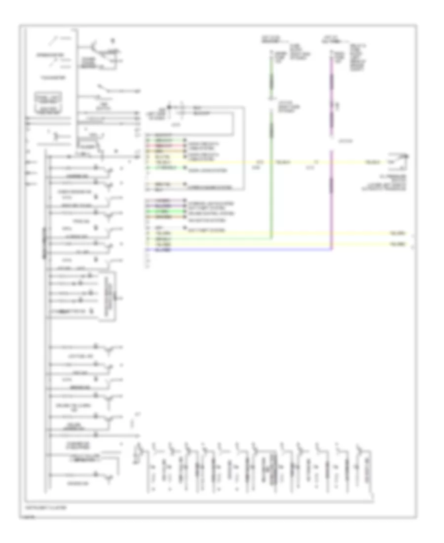
INSTRUMENT CLUSTER
Instrument Cluster Wiring Diagram (1 of 2) for Mazda 5 Touring 2013
List of elements for Instrument Cluster Wiring Diagram (1 of 2) for Mazda 5 Touring 2013:
- (a/t)
- A/t ind
- Abs ind
- Air bag ind
- Anti-theft system
- Brake ind
- Buzzer
- C-05
- C-13
- Charge ind
- Check engine ind
- Circuit failure detection
- Computer data lines system
- Cruise (amber) ind
- Cruise control system
- D & selector ind
- Dimmer cancel switch
- Door ind
- Door locks system
- Dsc ind
- Dsc off ind
- Ehpas ind
- Fuel cap ind
- Fuse block (right end of dash)
- G09 (left side of dash)
- Hi beam ind
- Hot at all times
- Hot in on or start
- Illum
- Ind (w/ malfunction warning light)
- Instrument cluster
- Interior lights system
- J/c 9
- J/c c-42 (right side of dash)
- J/c c-44
- Lh turn ind
- Low fuel ind
- Malfunction
- Meter fuse 10a
- Micro computer
- Navigation system
- Odo/trip fuel meter
- Oil ind
- Oil pressure switch (lower left side of automatic transaxle)
- Panel light control
- Relay & fuse block (left rear of engine compt)
- Rh turn ind
- Room fuse 15a
- Seat belts ind
- Security ind
- Selector indicator drive circuit
- Speedometer
- Tachometer
- Temp cool ind
- Temp hot ind
- Tns ind
- Tpms ind
- Trip switch
- Washer ind (if equipped)
- Wiper/washer system
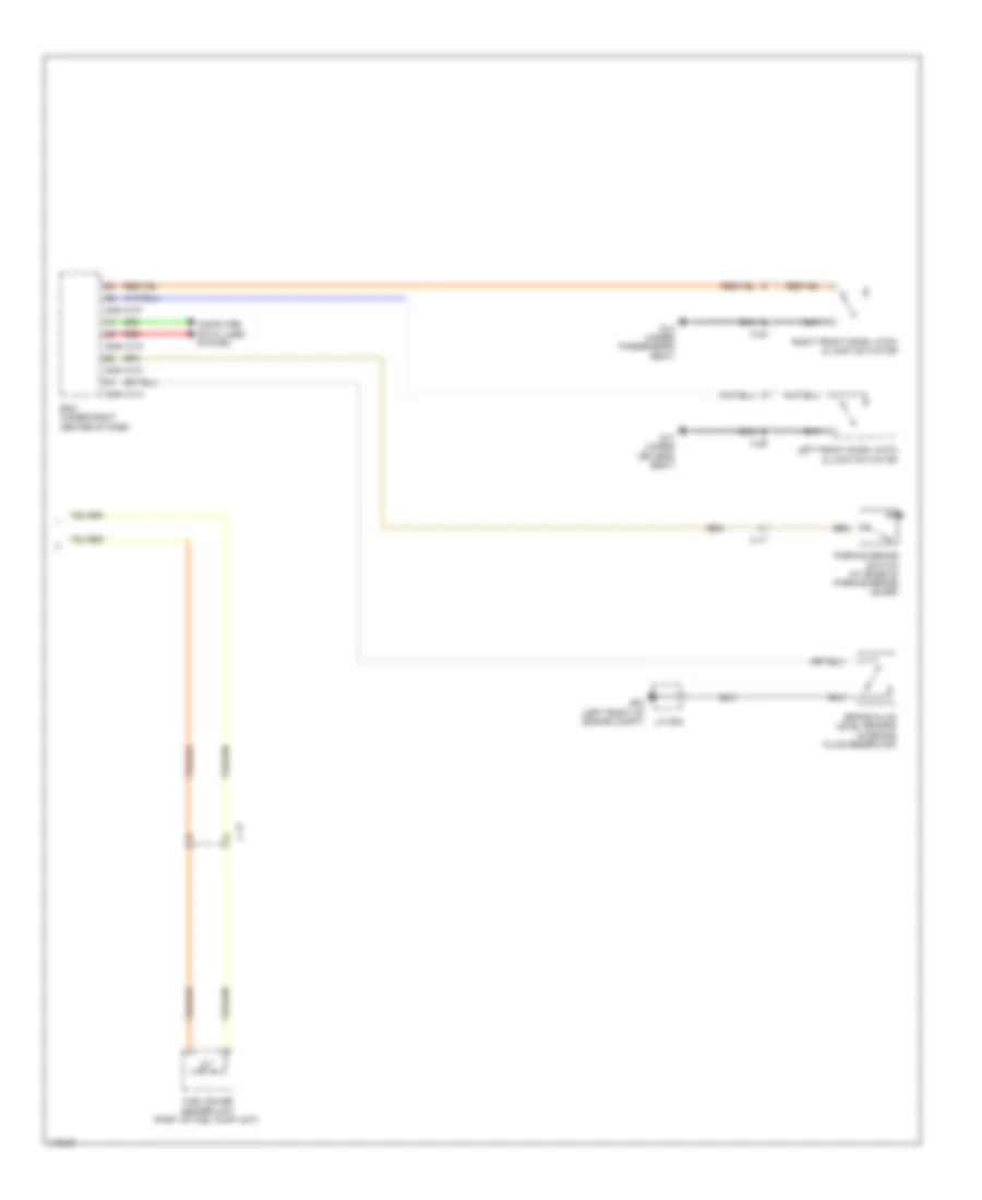
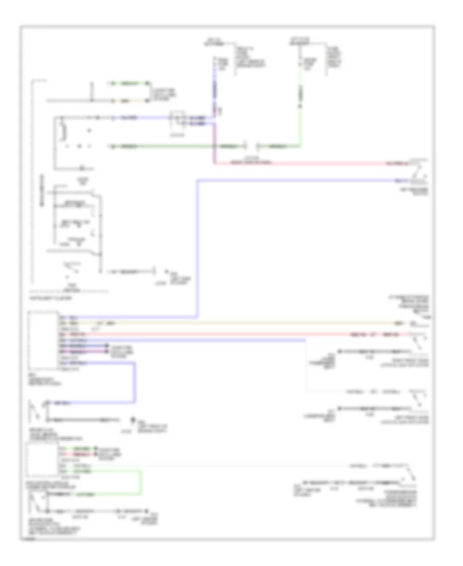
Instrument Cluster Wiring Diagram (2 of 2) for Mazda 5 Touring 2013
List of elements for Instrument Cluster Wiring Diagram (2 of 2) for Mazda 5 Touring 2013:
- 0940-101a
- 0940-101c
- 0940-101f
- Bcm (under right center of dash)
- Brake fluid level sensor (in brake fluid reservoir)
- C-17
- C-29
- C-30
- Computer data lines system
- Fuel gauge sender unit (part of fuel pump unit)
- G02 (left front of engine compt)
- G14 (under passenger's seat)
- G17 (under driver's seat)
- J/c g02
- Left front door latch & lock actuator
- Parking brake switch (at base of parking brake lever)
- Red
- Right front door latch & lock actuator
Multi-Information System Wiring Diagram for Mazda 5 Touring 2013
List of elements for Multi-Information System Wiring Diagram for Mazda 5 Touring 2013:
- 0922-201
- 0922-202
- C-05
- Clock spring (below steering wheel)
- Clock switch
- Computer data lines system
- Fuse block (right end of dash)
- G11 (right end of dash)
- Hot at all times
- Hot in on or acc
- Hot in on or start
- Info
- Information display
- Interior lights system
- J/c c-42 (right side of dash)
- J/c c-44
- Meter fuse 10a
- Mirror fuse 7.5a
- Nca
- Relay & fuse block (left rear of engine compt)
- Room fuse 15a
- Steering switch (if equipped)
INTERIOR LIGHTS
Courtesy Lamps Wiring Diagram for Mazda 5 Touring 2013
List of elements for Courtesy Lamps Wiring Diagram for Mazda 5 Touring 2013:
- 0940-101a
- 0940-101b
- 0940-101e
- 0940-101f
- Bcm (under right center of dash)
- C-20
- C-22
- C-29
- C-30
- Cargo compartment light
- Computer data lines system
- Door
- Front door latch switch
- G14 (under passenger's seat)
- G16 (left side of luggage compt)
- G17 (under driver's seat)
- Hot at all times
- Interior light
- Left front door latch & lock actuator
- Left sliding door switch (left "c" pillar)
- Liftgate latch switch (part of liftgate lock actuator assembly)
- Map light
- Off
- Red
- Relay & fuse block (left rear of engine compt)
- Right front door latch & lock actuator
- Right sliding door switch (right "c" pillar)
- Room fuse 15a
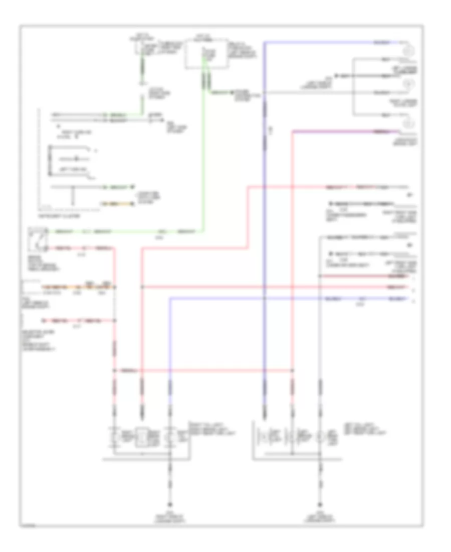
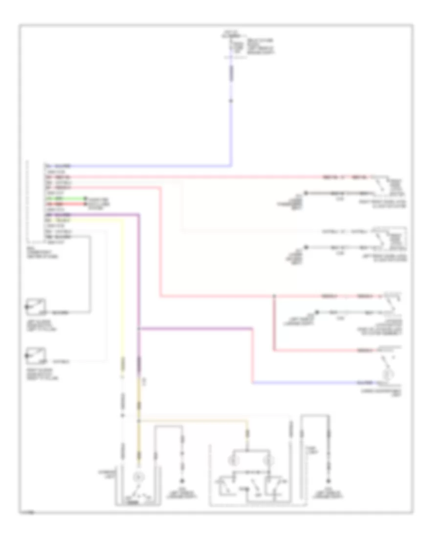
Instrument Illumination Wiring Diagram for Mazda 5 Touring 2013
List of elements for Instrument Illumination Wiring Diagram for Mazda 5 Touring 2013:
- (if equipped)
- 0740-201a
- 0920-201a
- 0922-201
- 0922-202
- 0940-101a
- 0940-101c
- 0940-101d
- Audio unit
- Auto
- Bcm (under right center of dash)
- Buzzer
- C-05
- C-18
- C-66
- Climate control unit
- Clock spring (below steering wheel)
- Computer data lines system
- Dimmer cancel switch
- Dsc off switch
- Exterior lights system
- G09 (left side of dash)
- Hazard warning switch
- Head
- Hot at all times
- Ignition key illumination
- Illumi fuse 7.5a
- Illumi ind
- Information display
- Instrument cluster
- J/c 09
- J/c c-44
- J/c c-50 (left end of dash)
- J/c c-51
- Left seat warmer switch
- Light switch
- Microcomputer
- Nca
- Off
- Rear fan switch
- Red
- Relay & fuse block (left rear of engine compt)
- Right seat warmer switch
- Room fuse 15a
- Selector lever component (if equipped) (base of shift lever assembly)
- Steering switch
- Tns
- Tns ind
- Tns relay (tail)
NAVIGATION
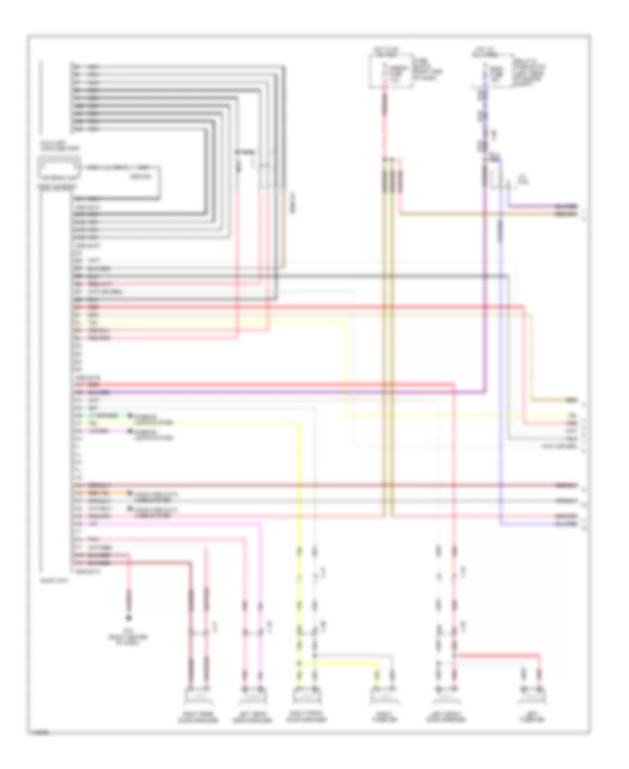
Navigation Wiring Diagram (1 of 2) for Mazda 5 Touring 2013
List of elements for Navigation Wiring Diagram (1 of 2) for Mazda 5 Touring 2013:
- 0920-201a
- 0920-201b
- 0920-201c
- 0920-201d
- 0920-202
- 0920-214
- 4ua
- 4ub
- 4uc
- 4ud
- Antenna amp
- Audio unit
- Auxiliary jack/usb port
- C-05
- C-17
- C-18
- C-29
- C-30
- Computer data lines system
- Fuse block (right end of dash)
- G10 (right center of dash)
- Hot at all times
- Hot in on or acc
- Interior lights system
- J/c c-44
- Left front door speaker
- Left rear door speaker
- Left tweeter
- Mirror fuse 7.5a
- Nca
- Pnk
- Red
- Relay & fuse block (left rear of engine compt)
- Right front door speaker
- Right rear door speaker
- Right tweeter
- Roof antenna
- Room fuse 15a
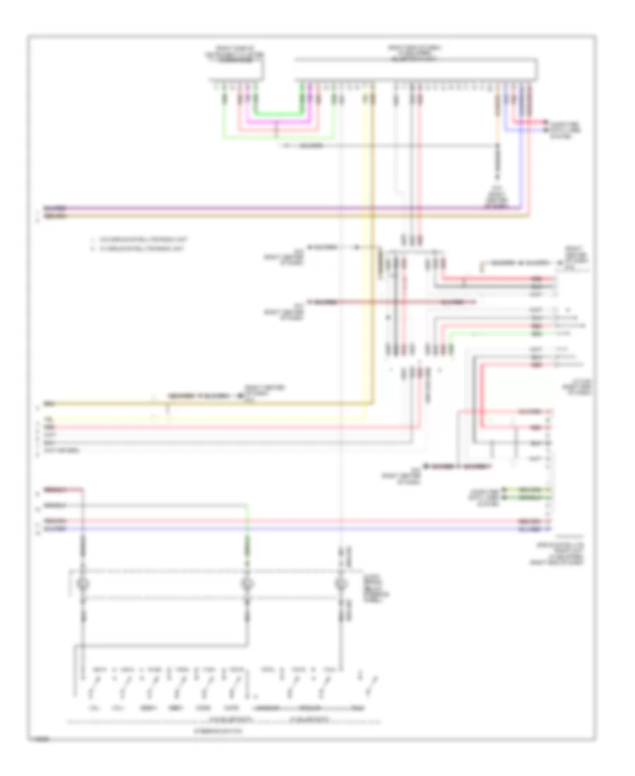
Navigation Wiring Diagram (2 of 2) for Mazda 5 Touring 2013
List of elements for Navigation Wiring Diagram (2 of 2) for Mazda 5 Touring 2013:
- (right
- (right center of dash) g10
- (right side of instrument cluster) microphone
- 0922-201
- 0922-202
- Center of dash) g10
- Clock spring (below steering wheel)
- Computer data lines system
- G10 (right center of dash)
- Hang-up
- J/c c-52 (right end of dash)
- Mode
- Mute
- Nca
- Pick-up
- Pnk
- Red
- Seek+
- Seek-
- Sirius satellite radio unit (if equipped) (right end of dash)
- Steering switch
- Talk
- Vol+
- Vol-
- W/ sirius satellite radio unit
- W/o sirius satellite radio unit
Parking Assistant Wiring Diagram for Mazda 5 Touring 2013
List of elements for Parking Assistant Wiring Diagram for Mazda 5 Touring 2013:
- C-70
- C-71
- C-72
- Computer data lines system
- Exterior lights system
- Fuse block (right end of dash)
- G09 (left side of dash)
- G10 (right center of dash)
- Hot in on or start
- Instrument cluster
- Interior lights system
- J/c c-42 (right side of dash)
- J/c g09
- Left back sensor (behind left side of rear bumper)
- Left corner sensor (behind left end of rear bumper)
- Meter fuse 10a
- Microcomputer
- Nca
- Parking sensor control module (right end of dash)
- Parking sensor switch
- Right back sensor (behind right side of rear bumper)
- Right corner sensor (behind right end of rear bumper)
- Trailer (option) (left "c" pillar)
POWER DISTRIBUTION
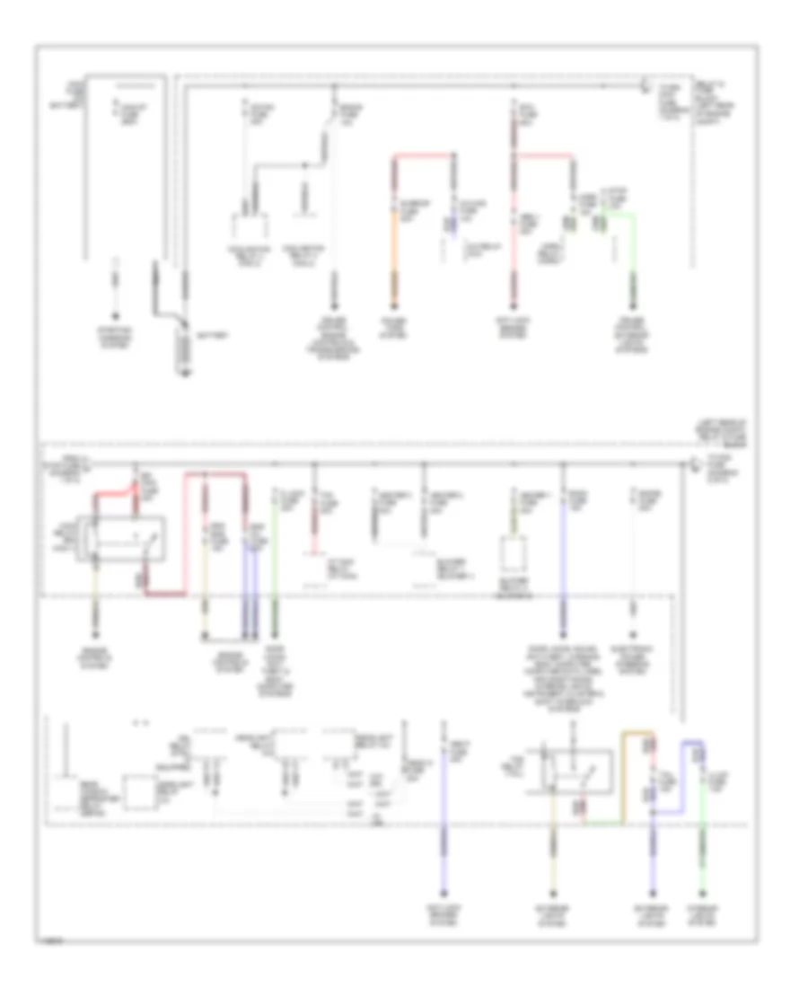
Power Distribution Wiring Diagram (1 of 2) for Mazda 5 Touring 2013
List of elements for Power Distribution Wiring Diagram (1 of 2) for Mazda 5 Touring 2013:
- (left rear of engine compt) relay & fuse block
- A/c mag fuse 10a
- A/c relay (a/c)
- Abs p fuse 40a
- Abs v fuse 20a
- Ad fan fuse 30a
- Anti-lock brakes system
- At main relay (at main)
- Battery
- Blower relay 1 (blower 1)
- Blower relay 2 (blower 2)
- Btn fuse 60a
- Compt)
- Cooling fan relay 2 (fan 2)
- Cooling fan relay 3 (fan 3)
- Cruise control, engine controls & transmissions systems
- Cruise control, exterior lights systems
- D lock fuse 20a
- Door locks, anti- theft & body computer systems
- Door locks, sound, anti-theft, warning, body computer, computer data lines, air conditioning, interior lights, instrument cluster & shift interlock systems
- Drl relay (dtrl) (if equipped)
- Egi main fuse 40a
- Ehpas fuse 80a
- Electronic power steering system
- Eng bar fuse 15a
- Eng inj fuse 25a
- Eng+b fuse 10a
- Engine controls system
- Exterior lights system
- From stop fuse a (diagram 1 of 2)
- Head hi fuse 20a
- Headlight relay (hi)
- Headlight relay (lo)
- Heater 1 fuse 40a
- Heater 2 fuse 30a
- Heater 3 fuse 30a
- Horn fuse 15a
- Horn relay (horn)
- Illumi fuse 7.5a
- Interior lights system
- Main fuse (on battery)
- Main relay (egi main 1)
- Main st fuse 250a
- Nca
- Power tops system
- Rear window defroster relay (defog)
- Red
- Relay & fuse block (left rear of engine
- Room fuse 15a
- Starting/ charging system
- Stop fuse 10a
- Sunroof fuse 20a
- Tail fuse 15a
- Tcm fuse 20a
- Tns relay (tail)
- To egi main fuse (diagram 1 of 2)
- To fog fuse (diagram 2 of 2)
- W/ drl
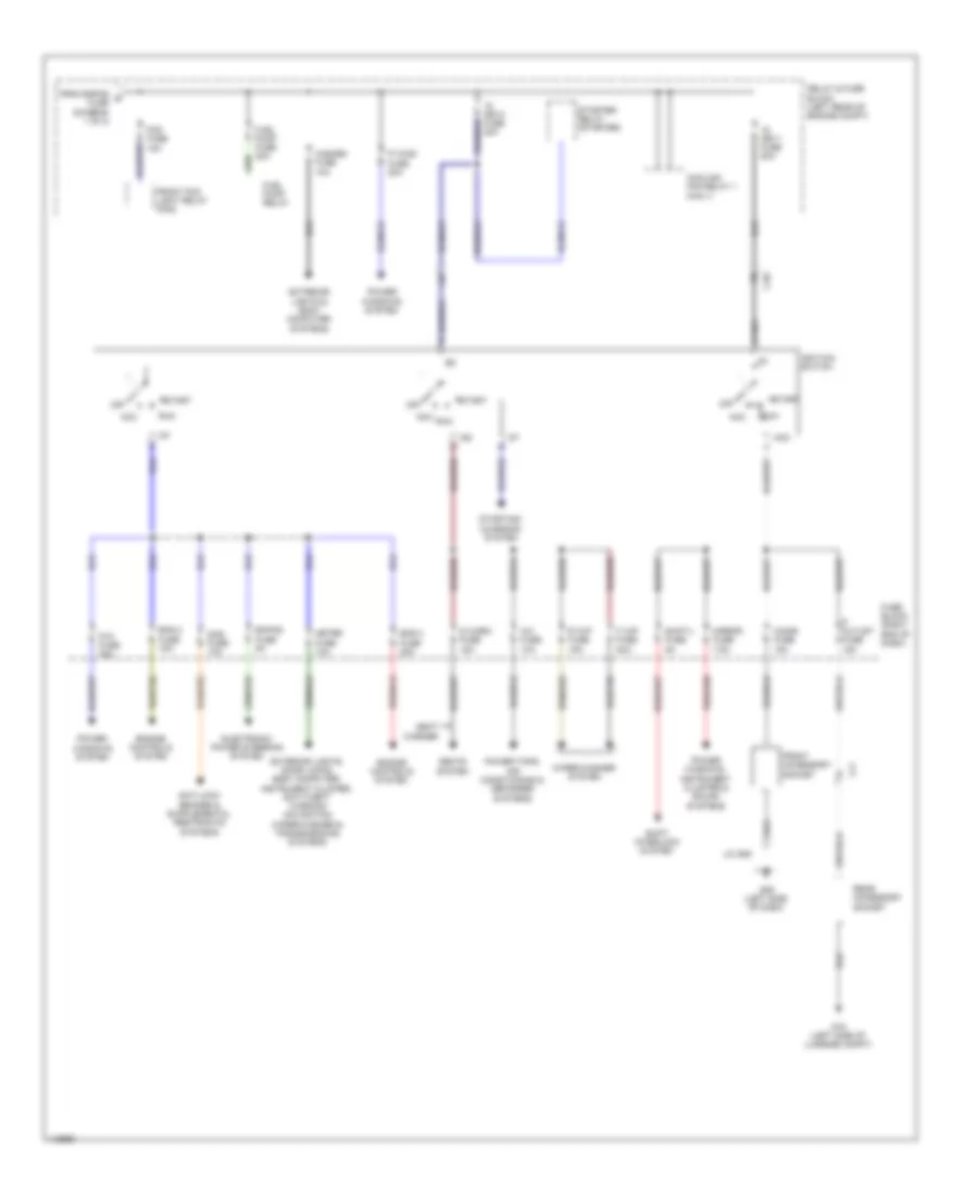
Power Distribution Wiring Diagram (2 of 2) for Mazda 5 Touring 2013
List of elements for Power Distribution Wiring Diagram (2 of 2) for Mazda 5 Touring 2013:
- A/c fuse 10a
- Acc
- C-05
- C17
- Cigar fuse 15a
- Cooling fan relay 1 (fan 1)
- Ehpas fuse 5a
- Electronic power steering system
- Eng 2 fuse 15a
- Eng 3 fuse 20a
- Engine controls system
- Exterior lights & body computer systems
- Exterior lights, door locks, body computer, instrument cluster, anti-theft, warning navigation wiper/washer & transmissions systems
- F wip fuse 25a
- Fog fuse 15a
- From ehpas b fuse (diagram 1 of 2)
- Front accessory socket
- Front fog light relay (fog)
- Fuel pump fuse 20a
- Fuel pump relay
- Fuse block (right end of dash)
- G09 (left side of dash)
- G16 (left side of luggage compt)
- Hazard fuse 10a
- Ig key1 fuse 50a
- Ig key2 fuse 40a
- Ig1
- Ig2
- Ignition switch
- J/c g09
- Meter fuse 10a
- Mirror fuse 7.5a
- Off
- P outlet fuse 15a
- P wind fuse 20a
- P/w fuse 30a
- Power tops, air conditioning & defogger systems
- Power windows system
- Power windows, instrument cluster & sound systems
- R wip fuse 15a
- Rear accessory socket
- Relay & fuse block (left rear of engine compt)
- Run
- S warm fuse 15a
- Sas fuse 10a
- Seat warmer
- Seats system
- Shift interlock system
- Shift/l fuse 5a
- Start
- Starter relay (starter)
- Starting/ charging system
- Wiper/washer system
POWER DOOR LOCKS
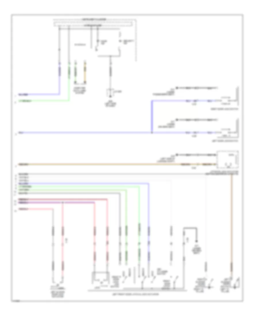
Power Door Locks Wiring Diagram (1 of 2) for Mazda 5 Touring 2013
List of elements for Power Door Locks Wiring Diagram (1 of 2) for Mazda 5 Touring 2013:
- (if equipped)
- (under driver's seat) g17
- (under passenger's seat) g14
- 0940-101a
- 0940-101c
- 0940-101d
- 0940-101e
- 0940-101f
- Bcm (under right center of dash)
- C-05
- C-17
- C-18
- C-20
- C-30
- C-31
- C-32
- Computer data lines system
- D lock fuse 20a
- Front door latch switch
- Front door lock- link switch
- Fuse block (right end of dash)
- G02 (left front of engine compt)
- G11 (right end of dash)
- G16 (left side of luggage compt)
- Hood latch switch (center front of engine compt)
- Hot at all times
- Hot in on or start
- J/c c-42 (right side of dash)
- J/c c-44
- J/c g02
- J/c g11
- Key reminder switch (part of ignition switch assembly)
- Keyless receiver
- Left sliding door lock-
- Liftgate opener switch
- Link switch
- Lock
- Meter fuse 10a
- Relay & fuse block (left rear of engine compt)
- Right front door latch & lock actuator
- Right sliding door lock actuator
- Right sliding door lock-
- Room fuse 15a
- Unlock
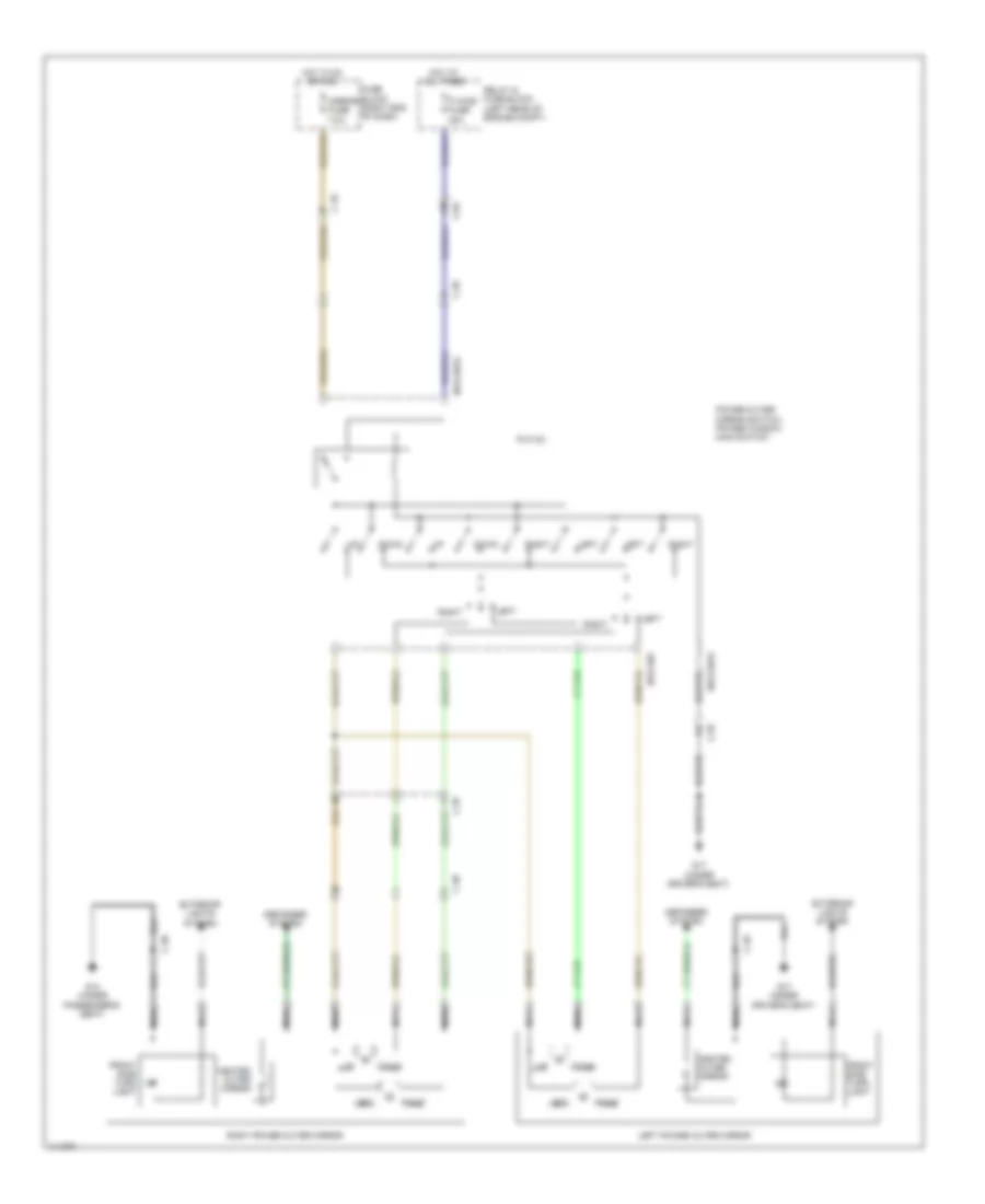
Power Door Locks Wiring Diagram (2 of 2) for Mazda 5 Touring 2013
List of elements for Power Door Locks Wiring Diagram (2 of 2) for Mazda 5 Touring 2013:
- (left "c" pillar)
- (under
- C-20
- C-29
- C-30
- C-32
- Computer data lines system
- Door ind
- Driver's seat)
- Front door latch switch
- Front door lock- link switch
- G09 (left side of dash)
- G14 (under passenger's seat)
- G16 (left side of
- G17
- G17 (under driver's seat)
- Instrument cluster
- J/c g09
- Key cylinder switch
- Left door lock switch
- Left front door latch & lock actuator
- Left sliding door lock actuator
- Left sliding door switch
- Liftgate lock actuator (bottom center of liftgate)
- Lock
- Luggage compt)
- Microcomputer
- Right door lock switch
- Right sliding door switch (right "c" pillar)
- Security ind
- Unlock
POWER MIRRORS
Power Mirrors Wiring Diagram for Mazda 5 Touring 2013
List of elements for Power Mirrors Wiring Diagram for Mazda 5 Touring 2013:
- 0912-201a
- 0912-301
- C-04
- C-18
- C-29
- C-30
- Defogger system
- Down
- Exterior lights system
- Front side turn light
- Fuse block (right end of dash)
- G14 (under passenger's seat)
- G17 (under driver's seat)
- Heated outer mirror
- Hot at all times
- Hot in on or acc
- Left
- Left power outer mirror
- Mirror fuse 7.5a
- Nca
- P wind fuse 20a
- P/w cm
- Power outer mirror switch/ power window main switch
- Relay & fuse block (left rear of engine compt)
- Right
- Right power outer mirror
POWER SEATS
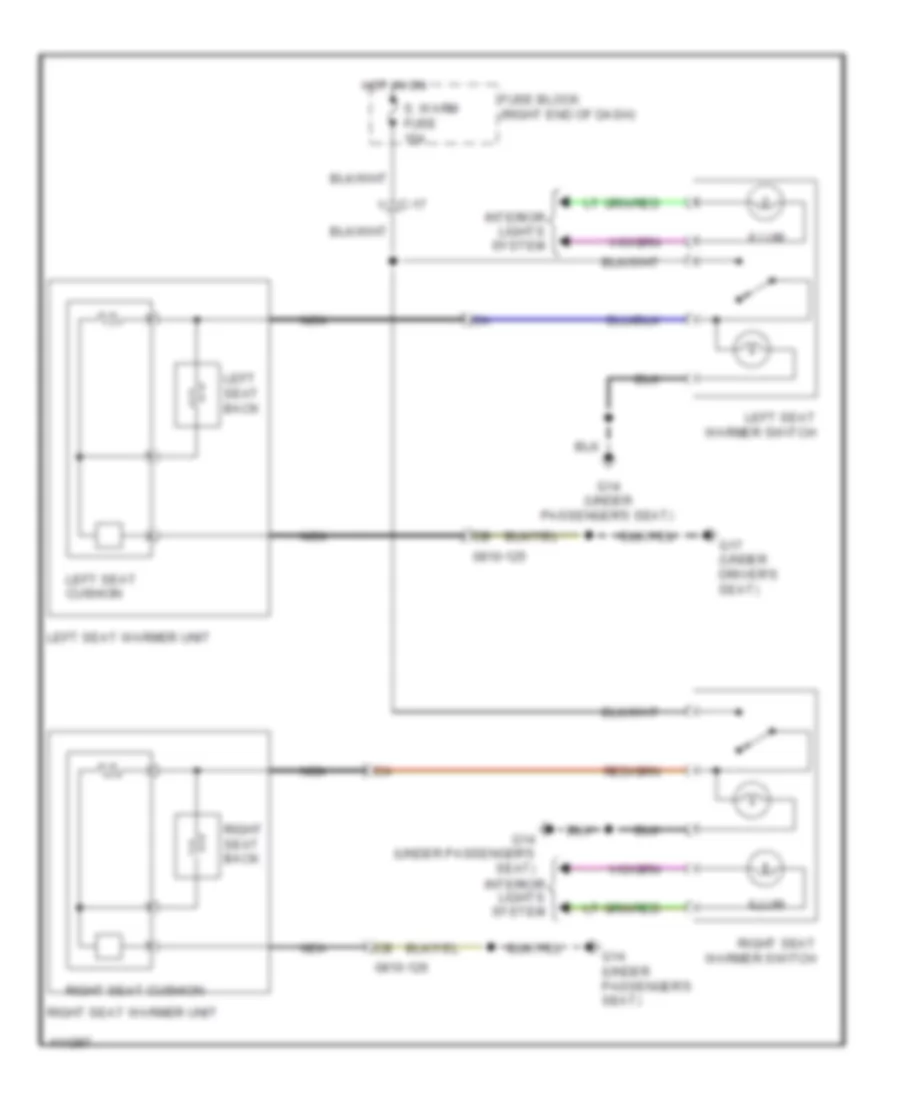
Power Seats Wiring Diagram for Mazda 5 Touring 2013
List of elements for Power Seats Wiring Diagram for Mazda 5 Touring 2013:
- 0810-125
- 0810-126
- C-17
- Fuse block (right end of dash)
- G14 (under passenger's seat)
- G17 (under driver's seat)
- Hot in on
- Illum
- Interior lights system
- Left seat back
- Left seat cushion
- Left seat warmer switch
- Left seat warmer unit
- Nca
- Right seat back
- Right seat cushion
- Right seat warmer switch
- Right seat warmer unit
- S. warm fuse 15a
POWER TOP/SUNROOF
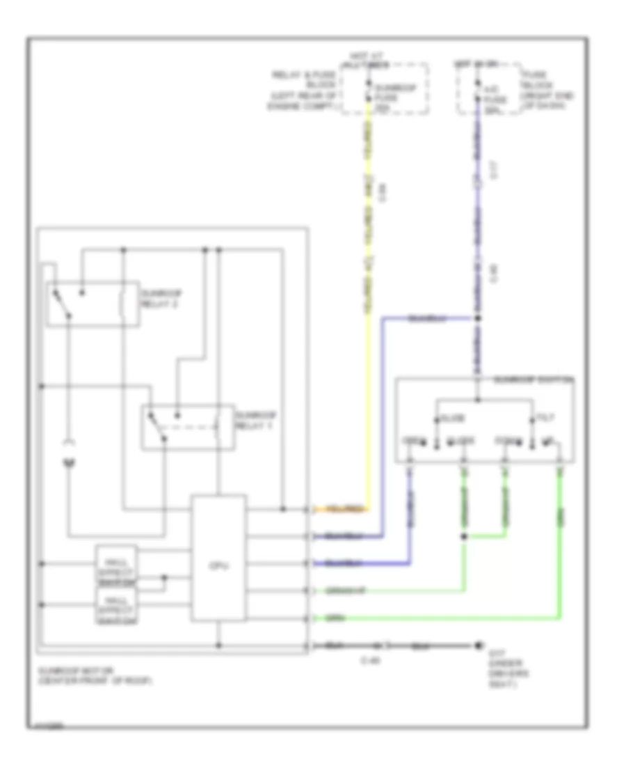
Power Top/Sunroof Wiring Diagram for Mazda 5 Touring 2013
List of elements for Power Top/Sunroof Wiring Diagram for Mazda 5 Touring 2013:
- A/c fuse 10a
- C-04
- C-17
- C-40
- Close
- Cpu
- Down
- Fuse block (right end of dash)
- G17 (under driver's seat)
- Hall effect switch
- Hot at all times
- Hot in on
- Open
- Relay & fuse block (left rear of engine compt)
- Slide
- Sunroof fuse 20a
- Sunroof motor (center front of roof)
- Sunroof relay 1
- Sunroof relay 2
- Sunroof switch
- Tilt
POWER WINDOWS
Power Windows Wiring Diagram for Mazda 5 Touring 2013
List of elements for Power Windows Wiring Diagram for Mazda 5 Touring 2013:
- 0912-201a
- 0912-201b
- 0940-101f
- Auto
- Bcm (under right center of dash)
- C-04
- C-17
- C-18
- C-29
- C-30
- C-31
- C-32
- Close
- Down
- Fuse block (right end of dash)
- G17 (under driver's seat)
- Hall effect switch 1
- Hot at all times
- Hot in acc or on
- Hot in on or start
- Left front power window motor
- Left rear power window motor
- Left rear power window sub switch
- Mirror fuse 7.5a
- Open
- Open m
- P wind fuse 20a
- P/w cm
- P/w fuse 30a
- Power outer mirror switch
- Power window main switch
- Power-cut switch
- Red
- Relay & fuse block (left rear of engine compt)
- Right front power window motor
- Right front power window sub switch
- Right rear power window motor
- Right rear power window sub switch
- Switch 2 hall effect
RADIO
Radio Wiring Diagram (1 of 2) for Mazda 5 Touring 2013
List of elements for Radio Wiring Diagram (1 of 2) for Mazda 5 Touring 2013:
- 0920-201a
- 0920-201b
- 0920-201c
- 0920-201d
- 0920-202
- 0920-214
- 4ua
- 4ub
- 4uc
- 4ud
- Antenna amp
- Audio unit
- Auxiliary jack/usb port
- C-05
- C-17
- C-18
- C-29
- C-30
- Computer data lines system
- Fuse block (right end of dash)
- G10 (right center of dash)
- Hot at all times
- Hot in on or acc
- Interior lights system
- J/c c-44
- Left front door speaker
- Left rear door speaker
- Left tweeter
- Mirror fuse 7.5a
- Nca
- Pnk
- Red
- Relay & fuse block (left rear of engine compt)
- Right front door speaker
- Right rear door speaker
- Right tweeter
- Roof antenna
- Room fuse 15a
Radio Wiring Diagram (2 of 2) for Mazda 5 Touring 2013
List of elements for Radio Wiring Diagram (2 of 2) for Mazda 5 Touring 2013:
- (right
- (right center of dash) g10
- (right side of instrument cluster) microphone
- 0922-201
- 0922-202
- Center of dash) g10
- Clock spring (below steering wheel)
- Computer data lines system
- G10 (right center of dash)
- Hang-up
- J/c c-52 (right end of dash)
- Mode
- Mute
- Nca
- Pick-up
- Pnk
- Red
- Seek+
- Seek-
- Sirius satellite radio unit (if equipped) (right end of dash)
- Steering switch
- Talk
- Vol+
- Vol-
- W/ sirius satellite radio unit
- W/o sirius satellite radio unit
SHIFT INTERLOCK
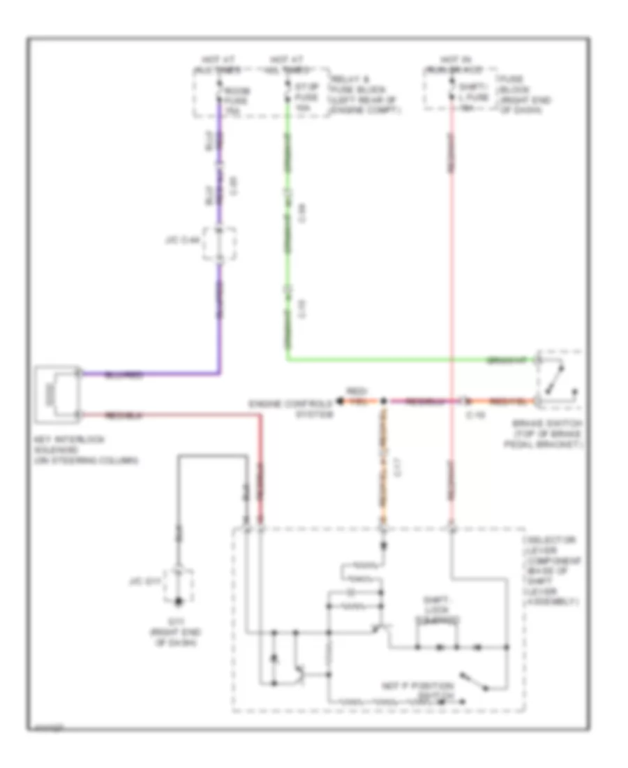
Shift Interlock Wiring Diagram for Mazda 5 Touring 2013
List of elements for Shift Interlock Wiring Diagram for Mazda 5 Touring 2013:
- (on steering column)
- Brake switch (top of brake pedal bracket)
- C-04
- C-05
- C-10
- C-17
- Engine controls system
- Fuse block (right end of dash)
- G11 (right end of dash)
- Hot at all times
- Hot in run or acc
- J/c c-44
- J/c g11
- Key interlock solenoid
- Not p position switch
- Relay & fuse block (left rear of engine compt)
- Room fuse 15a
- Selector lever component (base of shift lever assembly)
- Shift- lock solenoid
- Shift/ l fuse 15a
- Stop fuse 10a
STARTING/CHARGING
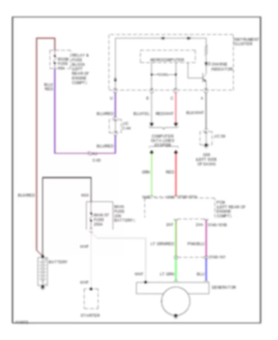
Charging Wiring Diagram for Mazda 5 Touring 2013
List of elements for Charging Wiring Diagram for Mazda 5 Touring 2013:
- 0140-101a
- 0140-141
- 1ai
- 1am
- 2aa 0140-101b
- 2af
- Battery
- C-05
- Charge
- Computer data lines system
- G09 (left side of dash)
- Generator
- Indicator
- Instrument cluster
- J/c 09
- J/c c-44
- Main fuse (on battery)
- Main st fuse 250a
- Microcomputer
- Nca
- Pcm (left rear of engine compt)
- Red
- Relay & fuse block (left rear of engine compt)
- Room fuse 15a
- Starter
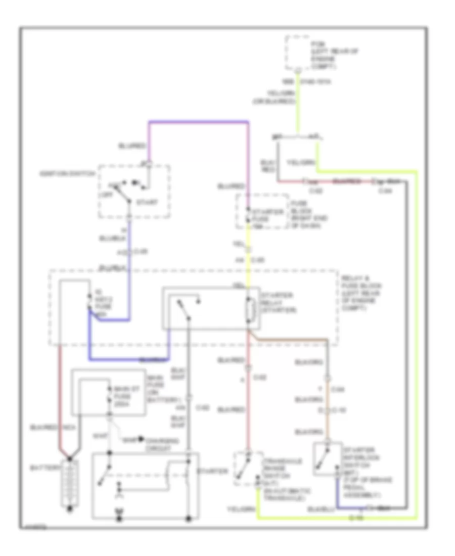
Starting Wiring Diagram for Mazda 5 Touring 2013
List of elements for Starting Wiring Diagram for Mazda 5 Touring 2013:
- 1bb 0140-101a
- A/t
- Acc
- Ak c-02
- Ak c-05
- Battery
- C-02
- C-04
- C-05 ao
- C-10
- Charging circuit
- Fuse block (right end of dash)
- Ig key2 fuse 40a
- Ignition switch
- L c-10
- M c-04
- M/t
- Main fuse (on battery)
- Main st fuse 250a
- Off
- Pcm (left rear of engine compt)
- Relay & fuse block (left rear of engine compt)
- Start
- Starter
- Starter fuse 10a
- Starter interlock switch (m/t) (top of brake pedal assembly)
- Starter relay (starter)
- Transaxle range switch (a/t) (in automatic transaxle)
SUPPLEMENTAL RESTRAINTS
Supplemental Restraints Wiring Diagram (1 of 2) for Mazda 5 Touring 2013
List of elements for Supplemental Restraints Wiring Diagram (1 of 2) for Mazda 5 Touring 2013:
- (integral to driver side seat belt buckle assembly) driver side buckle switch
- (left center of dash)
- (left side of dash)
- 0810-101a
- 0810-101b
- 0810-125
- 0810-126
- 2aa
- 2ab
- 2ac
- 2ad
- 2ae
- 2af
- 2ag
- 2ah
- 2ai
- 2aj
- 2ak
- 2al
- 2am
- 2an
- Air bag ind
- C-17
- C-18
- Circuit failure detection
- Computer data lines system
- Driver side curtain air bag module (in driver side "d" pillar)
- Driver-side side air bag module (outer edge of driver side seat back)
- Driver-side side air bag sensor 2 (near base of driver side "c" pillar)
- Fuse block (right end of dash)
- G09
- G12
- G12 (left center of dash)
- Hot in on or start
- Inflator
- Instrument cluster
- Joint conn- ector c-43 (right end of dash)
- Joint connector c-42 (right side of dash)
- Meter fuse 10a
- Micro computer
- Nca
- Passenger side air bag sensor 2 (near base of passenger side "c" pillar)
- Passenger side curtain air bag module (in passenger side "d" pillar)
- Passenger-side side air bag module (outer edge of passenger side seat back)
- Pnk
- Red
- Sas control module (under center console)
- Sas fuse 10a
- Seat belt ind
- Short bar
Supplemental Restraints Wiring Diagram (2 of 2) for Mazda 5 Touring 2013
List of elements for Supplemental Restraints Wiring Diagram (2 of 2) for Mazda 5 Touring 2013:
- (base of driver side "b" pillar) driver side pre-tensioner seat belt
- (base of passenger side "b" pillar) passenger side pre-tensioner seat belt
- (behind right side of dash) (w/ two step deployment control system) passenger side air bag module 2
- (behind right side of dash) passenger side air bag module 1
- (center front of engine compt) crash zone sensor
- (integral to passenger side seat belt buckle assembly) passenger side buckle switch
- (left center of dash)
- (w/ two step deployment control system) information display
- 0810-105
- 0810-124
- 0810-125
- 0810-126
- 0810-137a
- 0810-137b
- 0810-137c
- C-05
- C-18
- Clock spring (below steering wheel)
- Driver side air bag module 1 (in steering wheel)
- Driver side air bag module 2 (w/ two step deployment control system) (in steering wheel)
- Driver side side air bag sensor 1 (near base of driver side "b" pillar)
- G12
- G12 (left center of dash)
- Inflator
- Left seat weight sensor
- Nca
- Passenger side side air bag sensor 1 (near base of passenger side "b" pillar)
- Pnk
- Red
- Right seat weight sensor
- Seat track position sensor
- Seat weight sensor control module (w/ two step deployment control system) (under passenger's seat)
- Short bar
- W/ shield wire
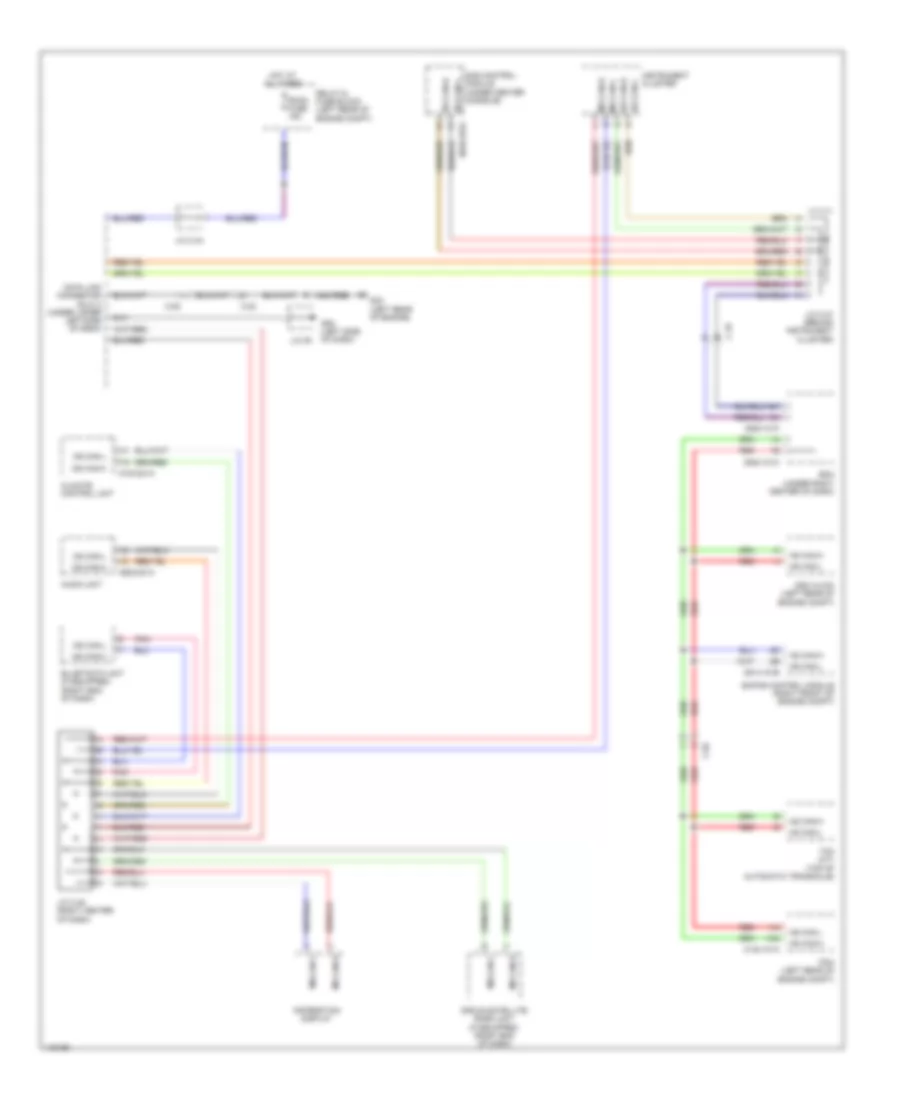
TRANSMISSION
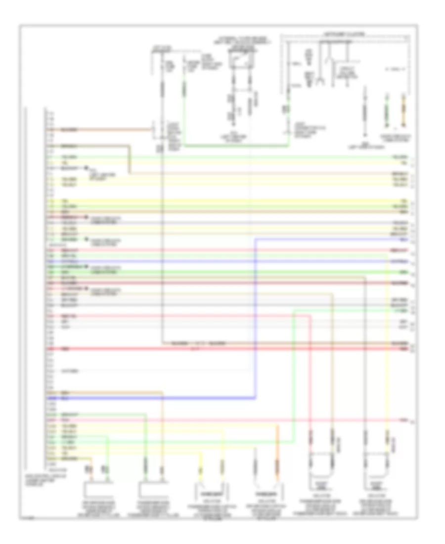
Transmission Wiring Diagram (1 of 2) for Mazda 5 Touring 2013
List of elements for Transmission Wiring Diagram (1 of 2) for Mazda 5 Touring 2013:
- (a/t)
- (in automatic transaxle control unit) g19
- 0517-105
- 0517-107
- A/t ind
- C-05
- Computer data lines system
- D & selector indicator light
- Fuse block (right end of dash)
- G09 (left side of dash)
- G20 (in automatic transaxle control unit)
- G23 (left rear of engine)
- Hot in on or start
- Input/turbine speed sensor (top of automatic transaxle)
- Instrument cluster
- J/c c-42 (right side of dash)
- J/c g09
- Meter fuse 10a
- Micro computer
- Oil pressure switch (lower left side of automatic transaxle)
- Pressure control solenoid b
- Primary solenoid valve
- Red
- Secondary solenoid valve
- Selector indicator drive circuit
- Solenoid a control pressure
- Solenoid a shift
- Solenoid b shift
- Solenoid c shift
- Solenoid d shift
- Solenoid e shift
- Solenoid f shift
- Tcm (top of automatic transaxle)
- Transaxle case
- Transaxle fluid temperature sensor
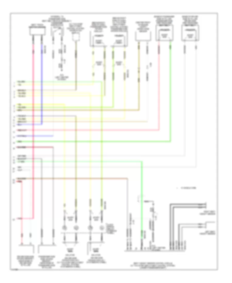
Transmission Wiring Diagram (2 of 2) for Mazda 5 Touring 2013
List of elements for Transmission Wiring Diagram (2 of 2) for Mazda 5 Touring 2013:
- A/t main relay
- C-02
- C-05
- Down switch
- Exterior lights system
- G11 (right end of dash)
- G23 (left rear of engine)
- Hot at all times
- Interior lights system
- Intermediate sensor (top of automatic transaxle)
- J/c g11
- M position switch
- Not p position switch
- R position switch
- Relay & fuse block (left rear of engine compt)
- Selector lever component
- Shift interlock system
- Shift lock solenoid
- Starting/ charging system
- Tcm fuse 20a
- Transaxle range switch (in automatic transaxle)
- Up switch
- Vehicle speed sensor (right side of automatic transaxle)
TRUNK, TAILGATE, FUEL DOOR
Trunk/Tailgate Release Wiring Diagram for Mazda 5 Touring 2013
List of elements for Trunk/Tailgate Release Wiring Diagram for Mazda 5 Touring 2013:
- 0940-101a
- 0940-101b
- 0940-101c
- 0940-101d
- 0940-101e
- 0940-101f
- Bcm (under right center of dash)
- C-05
- C-20
- Computer data lines system
- D lock fuse 20a
- G11 (right end of dash)
- G16 (left side of luggage compt)
- Hot at all times
- Interior lights system
- J/c g11
- Liftgate lock actuator/ liftgate latch switch (part of liftgate lock actuator assembly)
- Liftgate opener switch
- Red
- Relay & fuse block (left rear of engine compt)
- Room fuse 15a
WARNING SYSTEMS
Warning Systems Wiring Diagram for Mazda 5 Touring 2013
List of elements for Warning Systems Wiring Diagram for Mazda 5 Touring 2013:
- (at base of parking brake lever)
- 0810-101a
- 0810-101b
- 0810-125
- 0810-126
- 0940-101a
- 0940-101c
- 0940-101f
- Bcm (under right center of dash)
- Brake fluid level sensor (in brake fluid reservoir)
- Brake ind
- Buzzer
- C-05
- C-17
- C-18
- C-29
- C-30
- Computer data lines system
- Door ind
- Driver side buckle switch (integral to driver seat belt buckle assembly)
- Fuse block (right end of dash)
- G02 (left front of engine compt)
- G09 (left side of dash)
- G12 (left center of dash)
- G14 (under passenger's seat)
- G17 (under driver's seat)
- Hot at all times
- Hot in on or start
- Instrument cluster
- J/c c-42 (right side of dash)
- J/c c-44
- J/c-02
- J/c-09
- Key reminder switch
- Left front door latch & lock actuator
- Meter fuse 10a
- Microcomputer
- Nca
- Parking brake switch
- Passenger side buckle switch (integral to passenger seat belt buckle assembly)
- Relay & fuse block (left rear of engine compt)
- Right front door latch & lock actuator
- Room fuse 15a
- Sas control module (under center console)
- Seat belt ind
- Tpms ind
- Trip switch
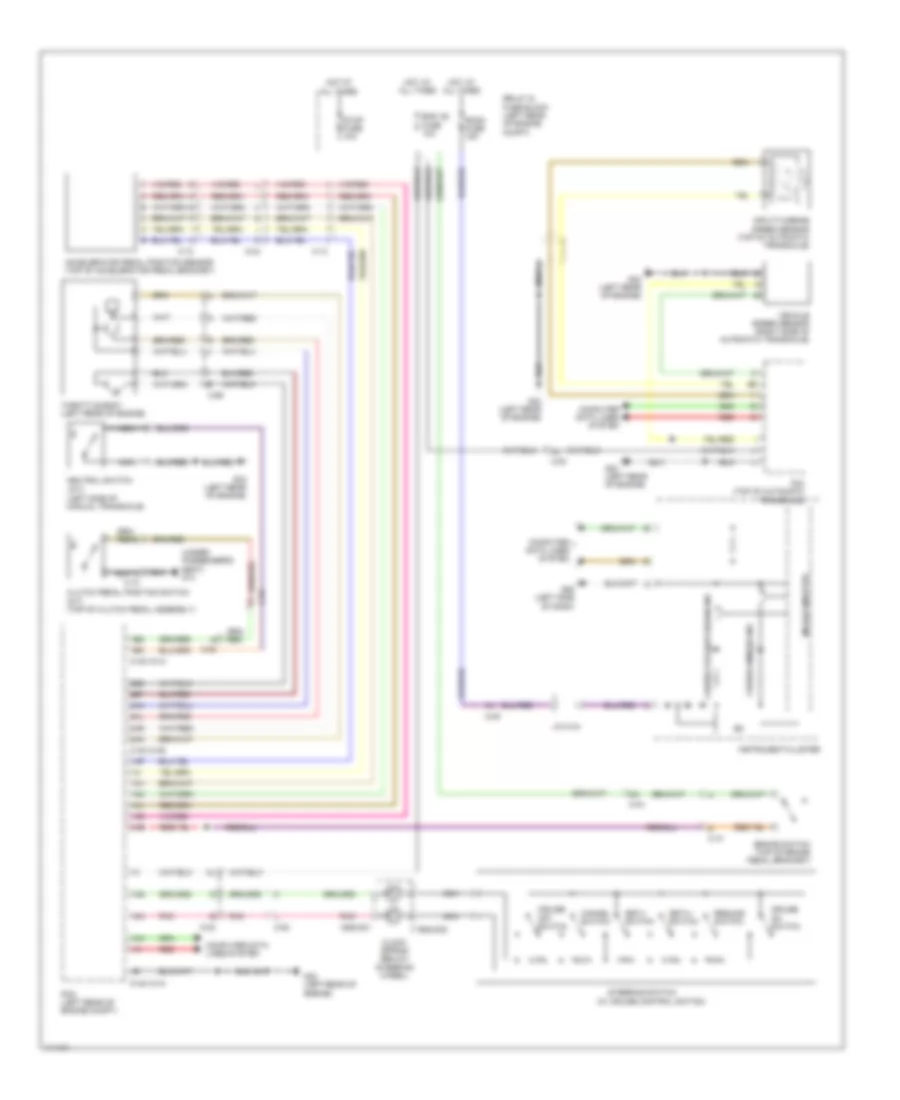
WIPER/WASHER
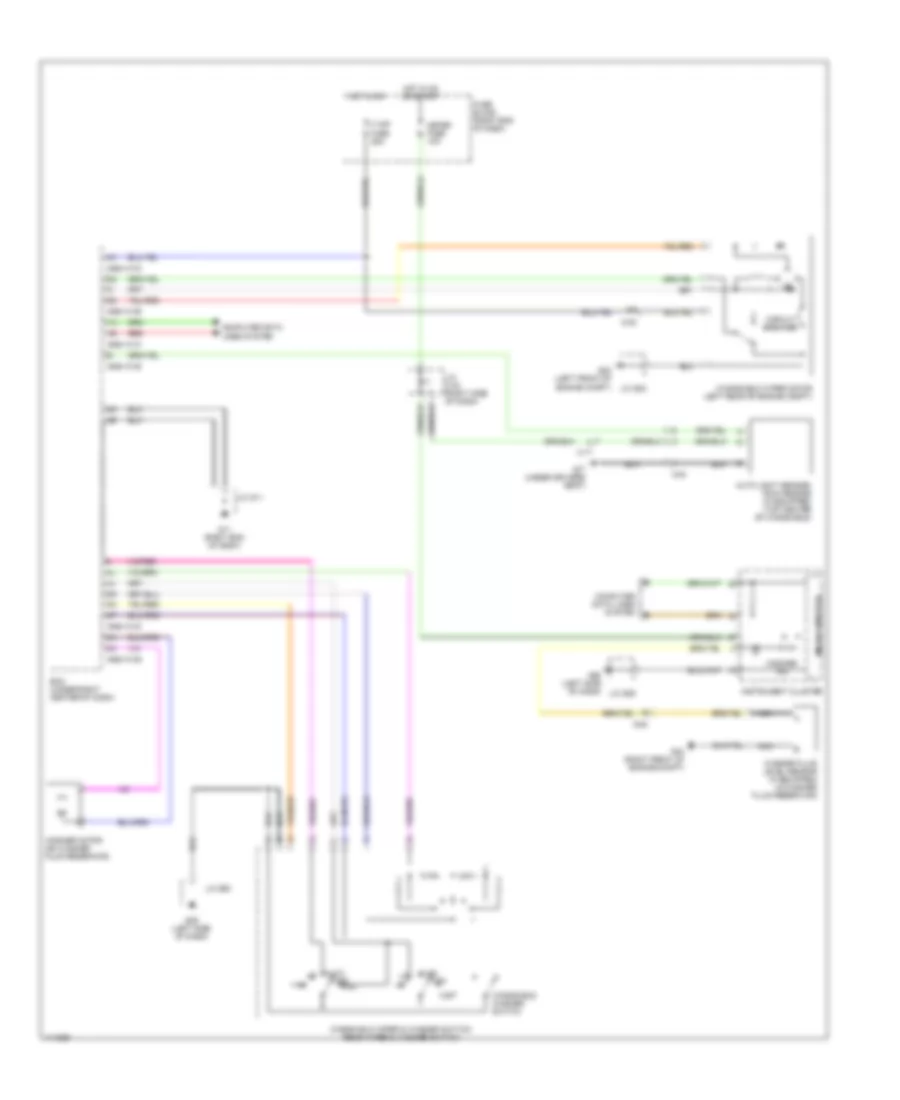
Front Wiper/Washer Wiring Diagram, with Auto Wiper System for Mazda 5 Touring 2013
List of elements for Front Wiper/Washer Wiring Diagram, with Auto Wiper System for Mazda 5 Touring 2013:
- 0940-101a
- 0940-101b
- 0940-101d
- 0940-101e
- Auto
- Auto light sensor/ rain sensor (if equipped) (top center of windshield)
- Bcm (under right center of dash)
- C-05
- C-17
- C-40
- Circuit breaker
- Computer data lines system
- F wip fuse 25a
- Fuse block (right end of dash)
- G02 (left front of engine compt)
- G04 (right front of engine compt)
- G09 (left side of dash)
- G11 (right end of dash)
- G17 (under driver's seat)
- Hot in on
- Hot in on or start
- Instrument cluster
- J/c c-42 (right side of dash)
- J/c g02
- J/c g09
- J/c g11
- Meter fuse 10a
- Microcomputer
- Mist
- Nca
- Off
- Red
- Washer fluid level sensor (if equipped) (in washer fluid reservoir)
- Washer ind
- Washer motor (on washer fluid reservoir)
- Windshield washer switch
- Windshield wiper & washer switch/ rear wiper & washer switch
- Windshield wiper motor (left rear of engine compt)
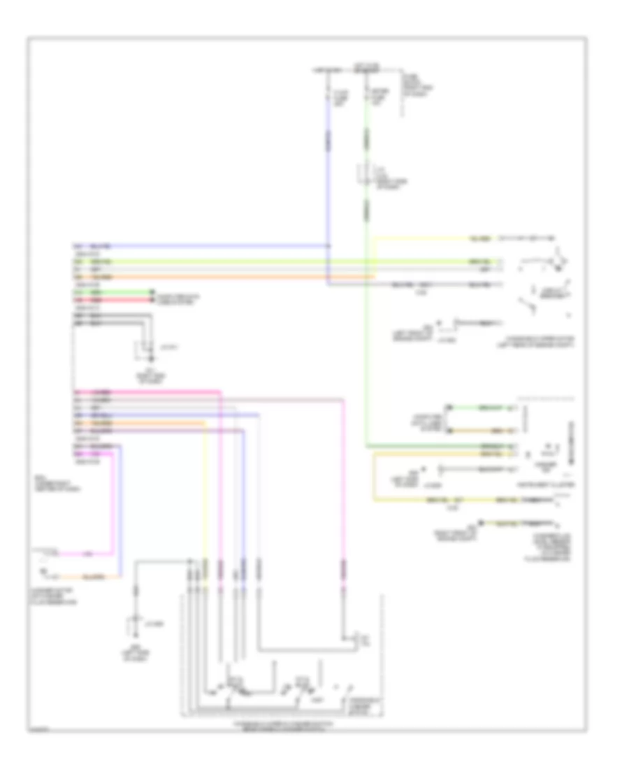
Front Wiper/Washer Wiring Diagram, without Auto Wiper System for Mazda 5 Touring 2013
List of elements for Front Wiper/Washer Wiring Diagram, without Auto Wiper System for Mazda 5 Touring 2013:
- 0940-101a
- 0940-101b
- 0940-101d
- Bcm (under right center of dash)
- C-05
- Circuit breaker
- Computer data lines system
- F wip fuse 25a
- Fuse block (right end of dash)
- G02 (left front of engine compt)
- G04 (right front of engine compt)
- G09 (left side of dash)
- G11 (right end of dash)
- Hot in on
- Hot in on or start
- Instrument cluster
- Int & auto
- Int vol
- J/c c-42 (right side of dash)
- J/c g02
- J/c g09
- J/c g11
- Meter fuse 10a
- Microcomputer
- Mist
- Nca
- Off
- Red
- Washer fluid level sensor (if equipped) (in washer fluid reservoir)
- Washer ind
- Washer motor (on washer fluid reservoir)
- Windshield washer switch
- Windshield wiper & washer switch/ rear wiper & washer switch
- Windshield wiper motor (left rear of engine compt)
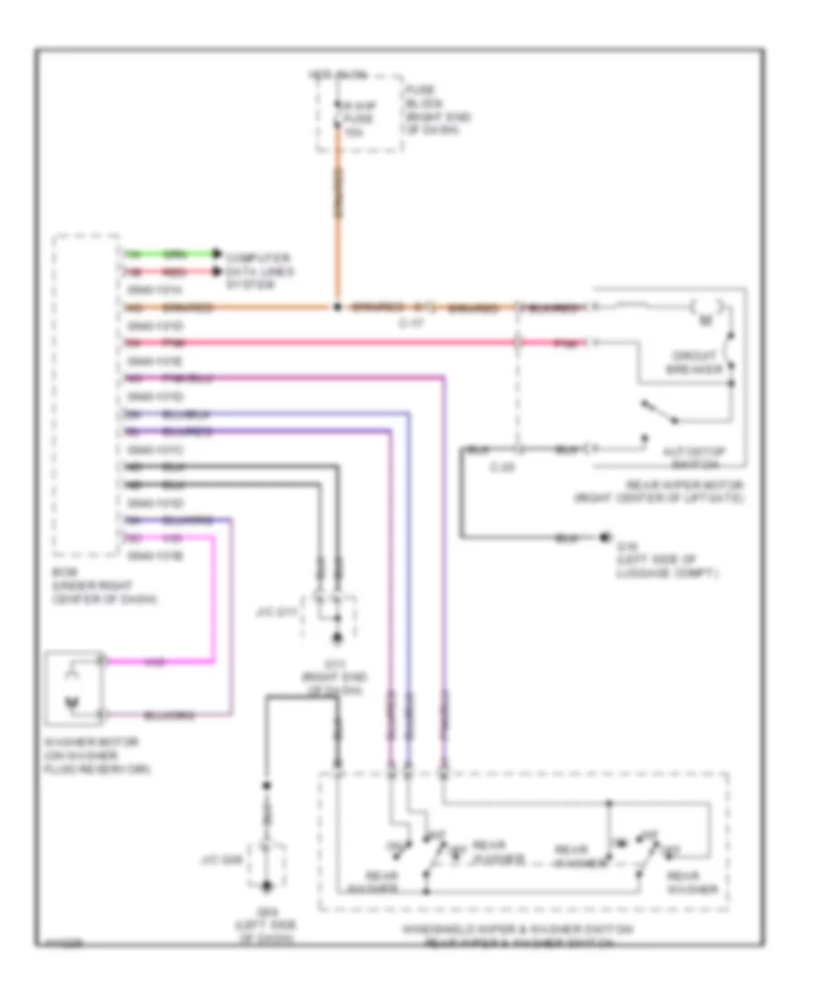
Rear Wiper/Washer Wiring Diagram for Mazda 5 Touring 2013
List of elements for Rear Wiper/Washer Wiring Diagram for Mazda 5 Touring 2013:
- 0940-101a
- 0940-101b
- 0940-101c
- 0940-101d
- 0940-101e
- Autostop switch
- Bcm (under right center of dash)
- C-17
- C-20
- Circuit breaker
- Computer data lines system
- Fuse block (right end of dash)
- G09 (left side of dash)
- G11 (right end of dash)
- G16 (left side of luggage compt)
- Hot in on
- Int
- J/c g09
- J/c g11
- Off
- Pnk
- R wip fuse 15a
- Rear washer
- Rear wiper motor (right center of liftgate)
- Red
- Washer motor (on washer fluid reservoir)
- Windshield wiper & washer switch/ rear wiper & washer switch

 Čeština
 Dansk
Dansk Deutsch
 Ελληνικά
 English
 English
 Español
 Français
 Français
 עברית
עברית Hrvatski
 Magyar
 Italiano
 日本語
日本語 한국어
한국어 Nederlands
 Polski
 Português
 Português
 Română
 Русский
 Slovenčina
 Slovenščina
 Svenska
 Türkçe
 中文 (中国)