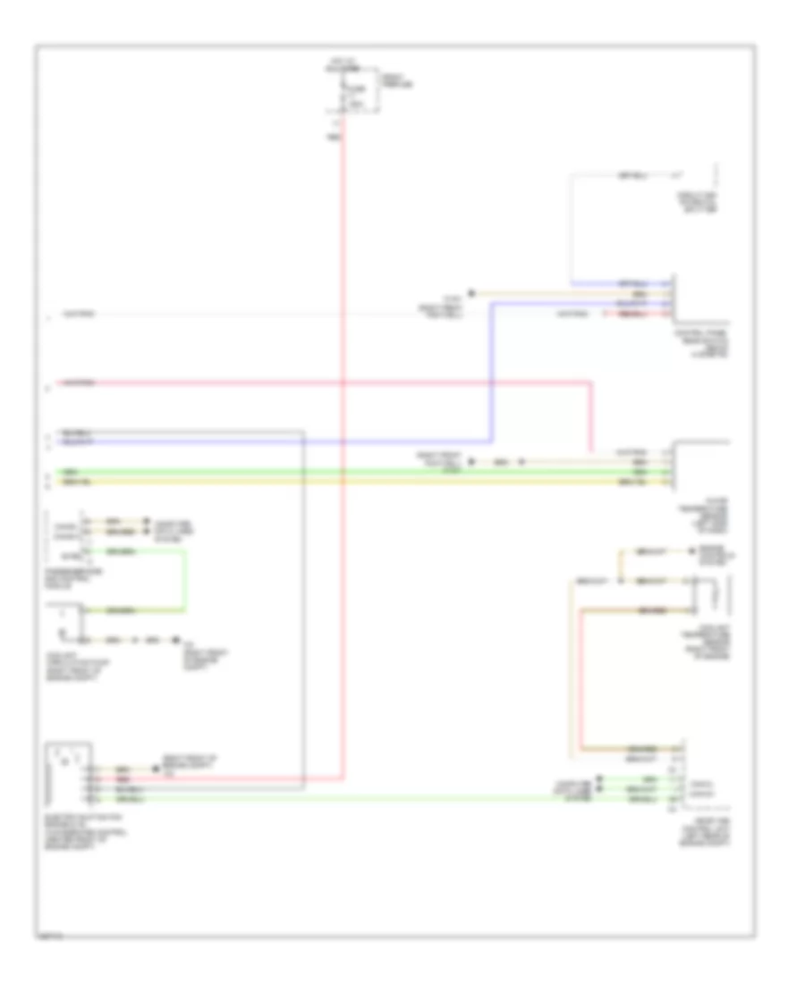
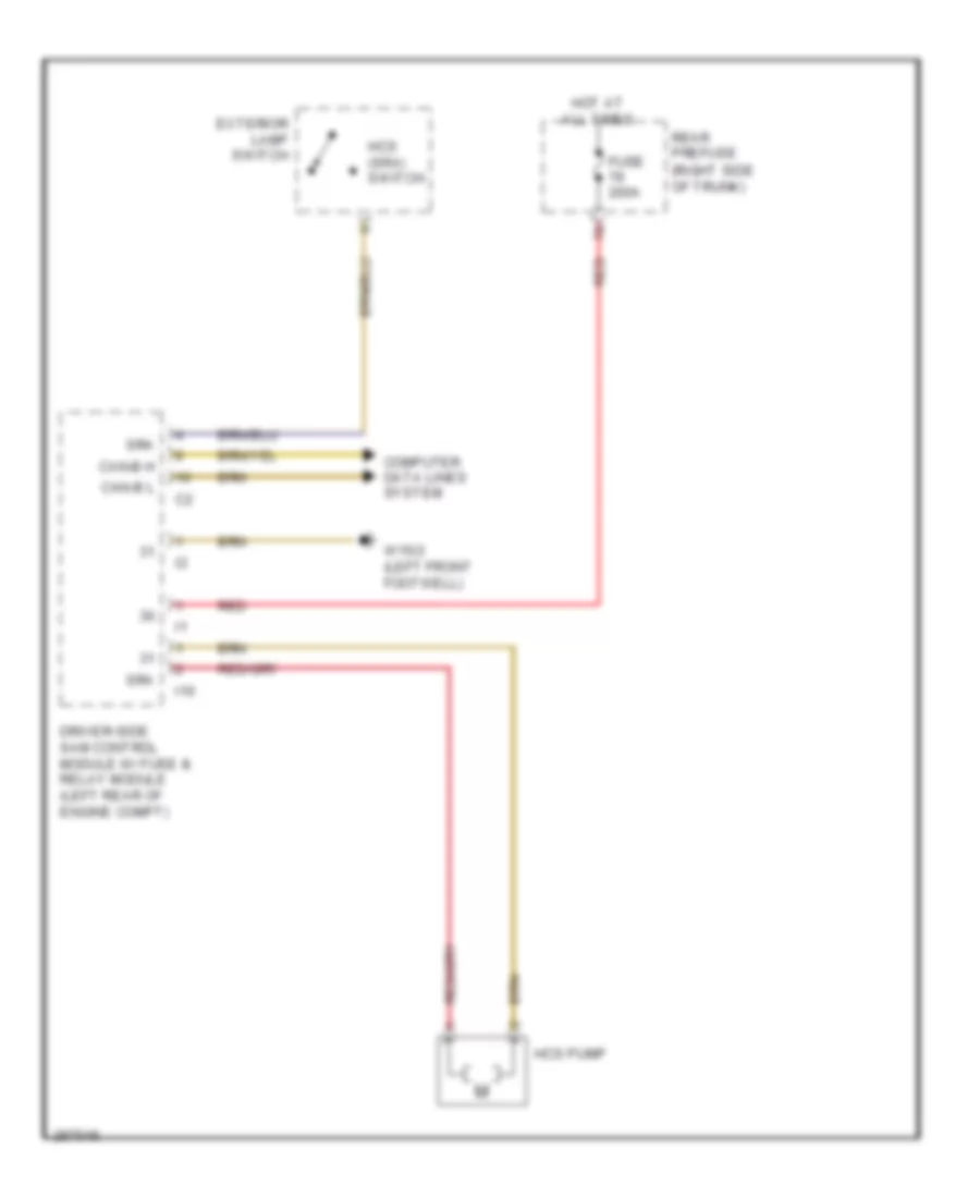
AIR CONDITIONING
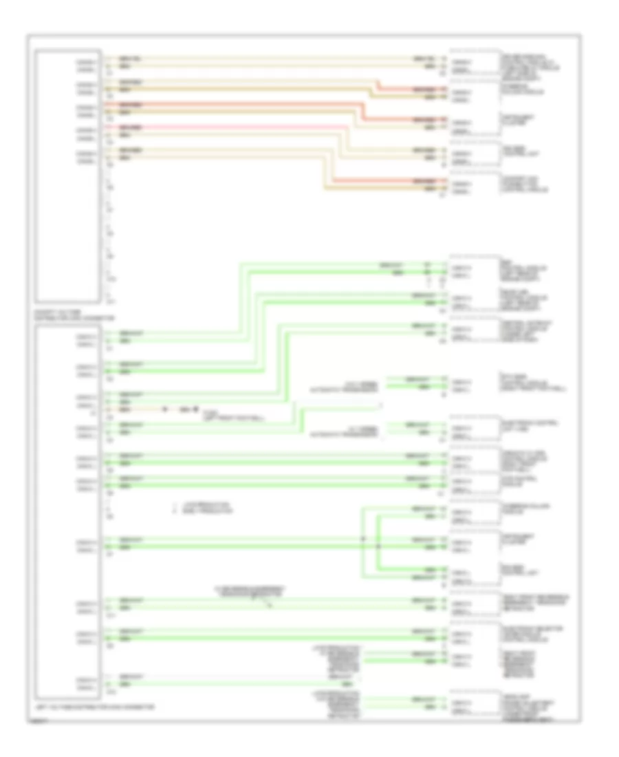
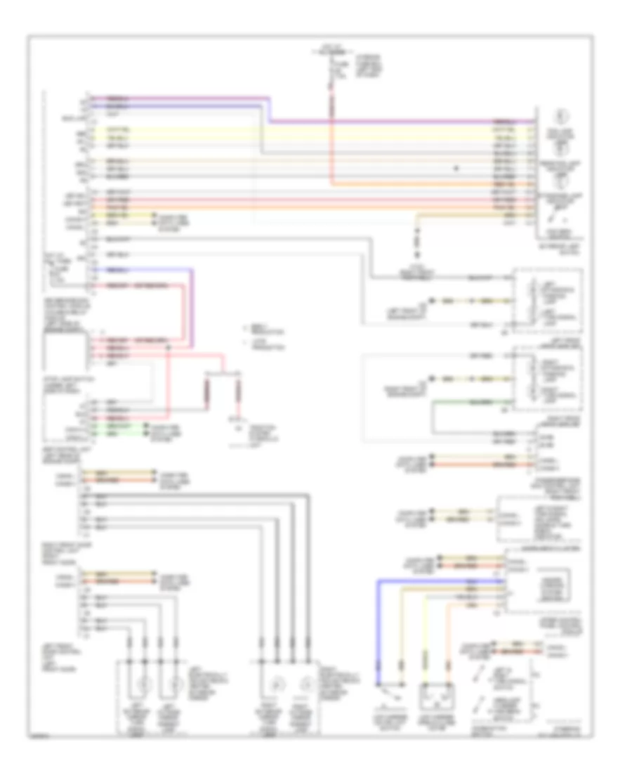
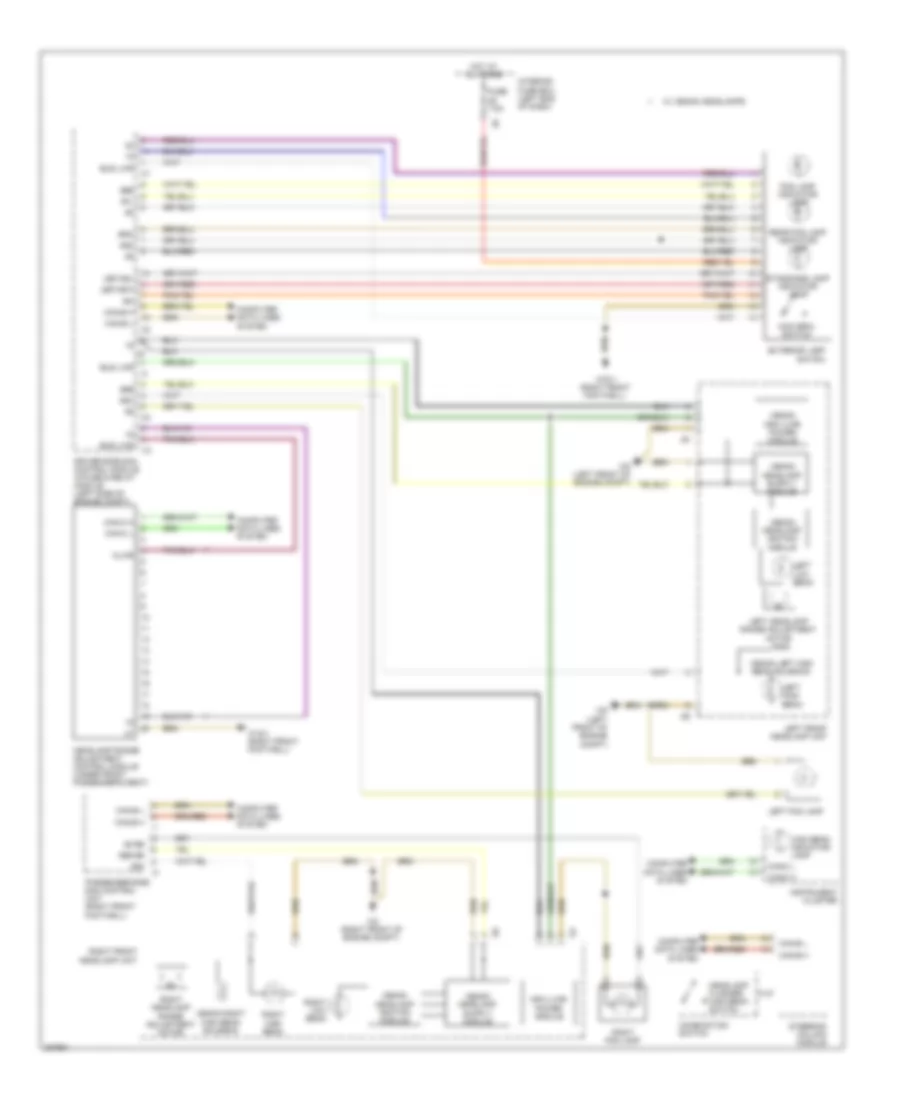
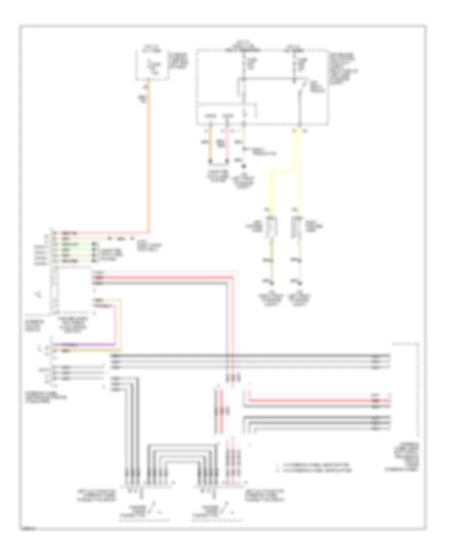
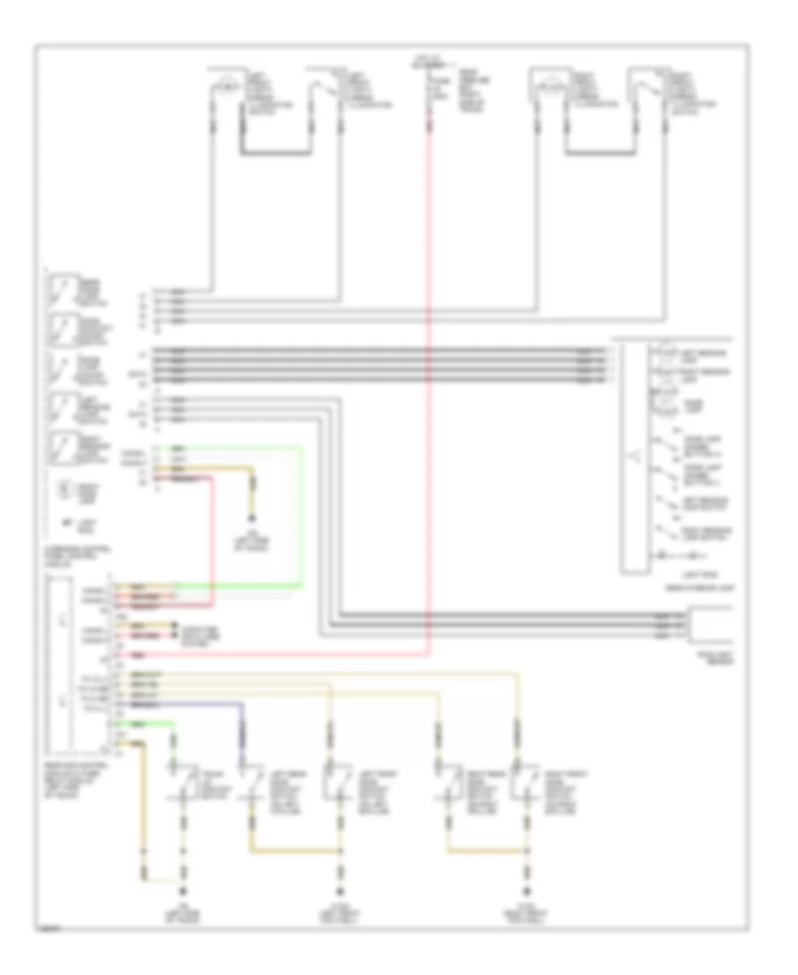
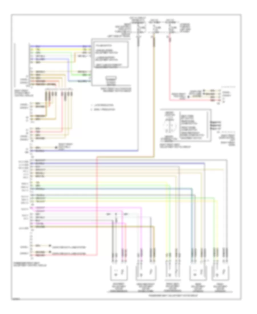
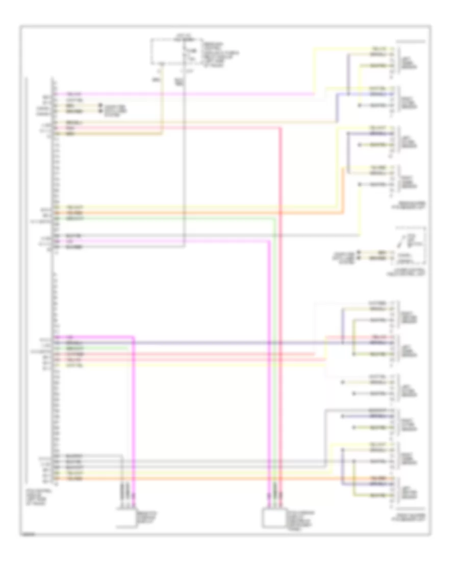
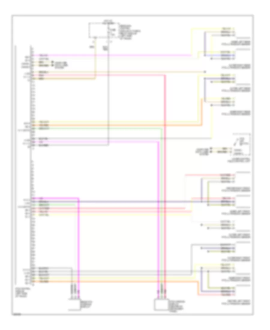
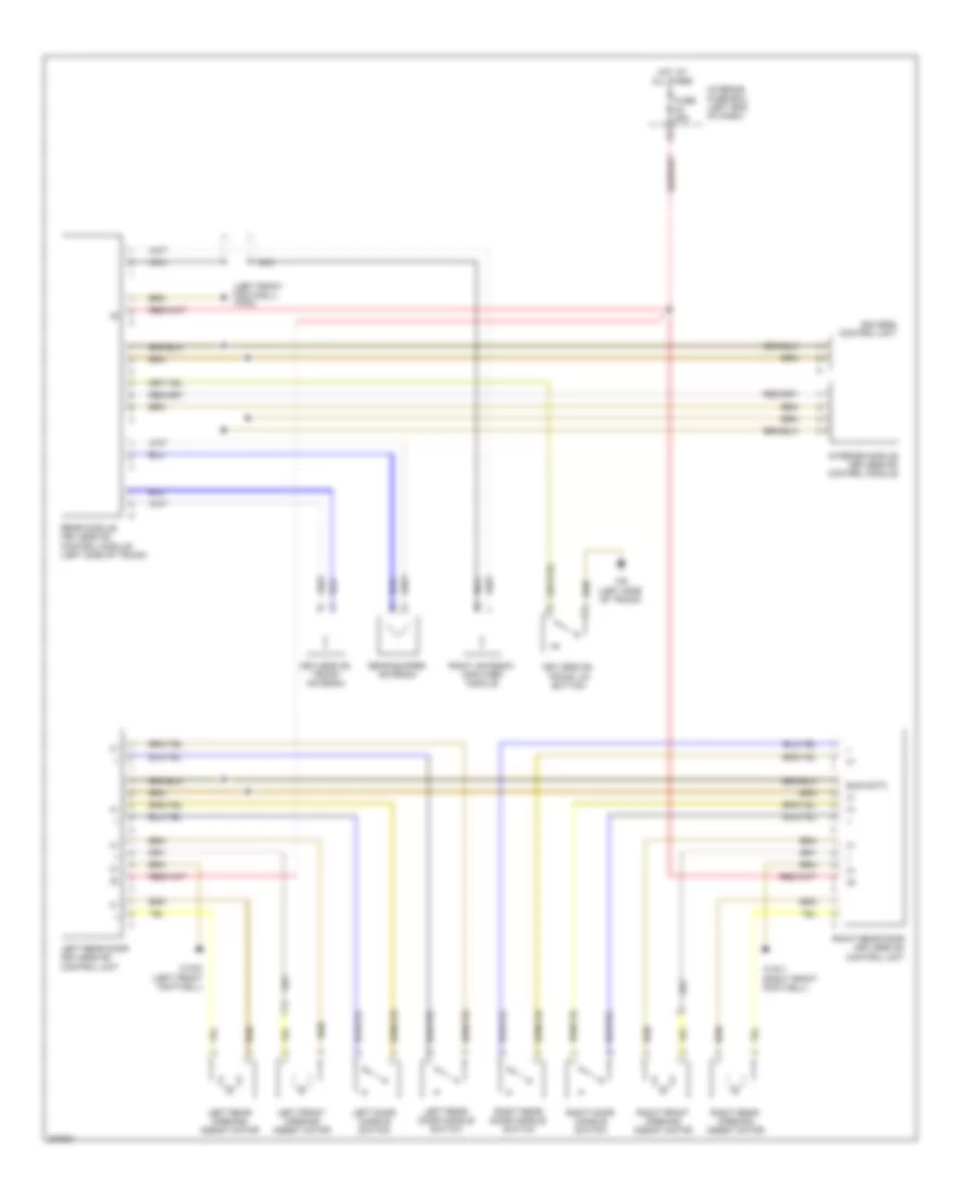
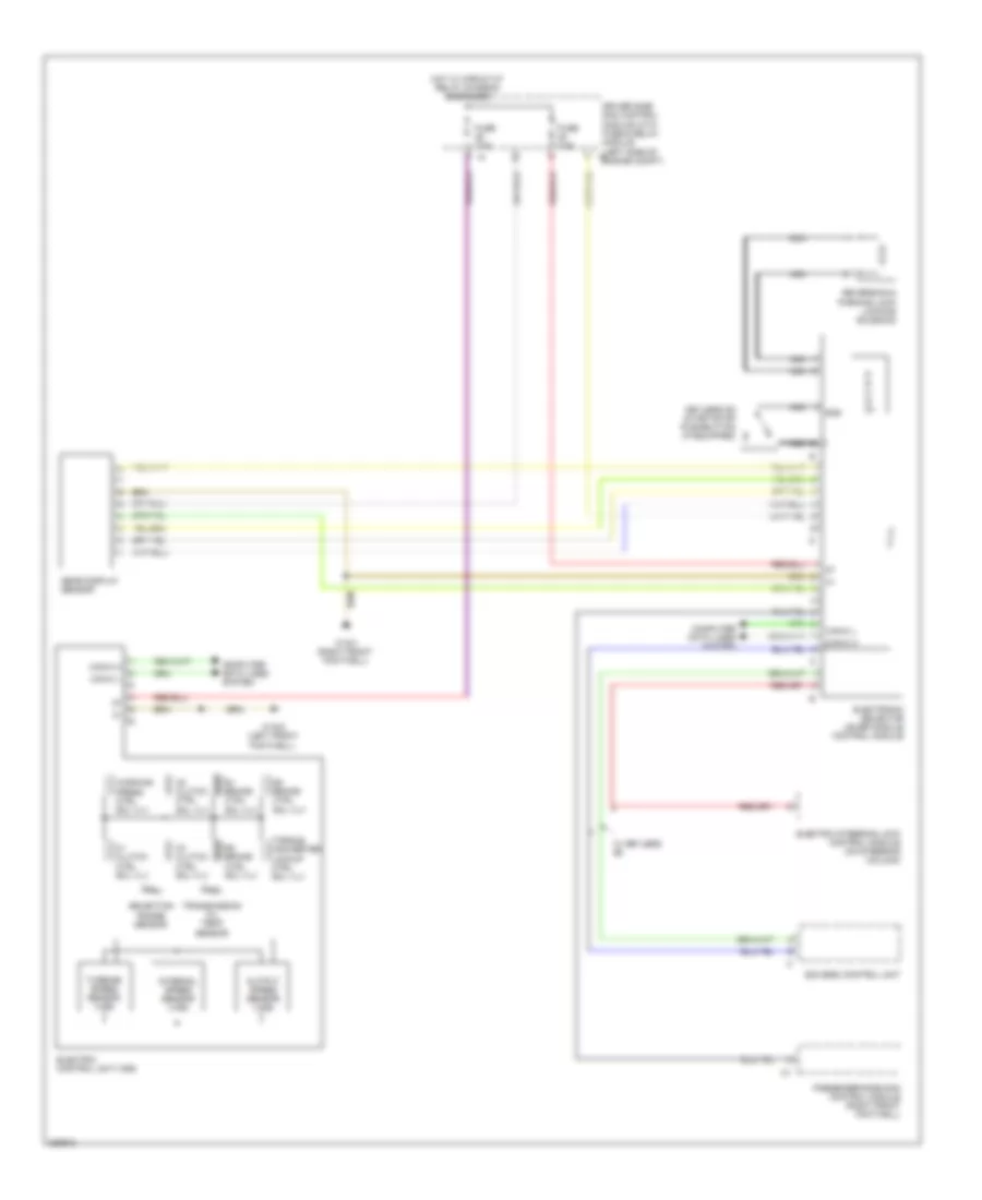
Automatic A/C Wiring Diagram (1 of 2) for Mercedes-Benz CLS500 2006
 https://portal-diagnostov.com/license.html
Automotive Electricians Portal FZCO
Automotive Electricians Portal FZCO
https://portal-diagnostov.com/license.html
https://portal-diagnostov.com/license.html
Automotive Electricians Portal FZCO
Automotive Electricians Portal FZCO
List of elements for Automatic A/C Wiring Diagram (1 of 2) for Mercedes-Benz CLS500 2006:
- (right front footwell) w15/1
- 12v
- Can-b h
- Can-b l
- Comfort aac pushbutton control module
- Computer data lines system
- Df sig
- Driver-side sam control module w/fuse & relay module (left side of engine compt)
- Early production
- Evaporator temperature sensor (left side of hvac unit)
- Fresh air/ recirculated air flap actuator motor (on hvac unit)
- Front prefuse
- Fuse 40a
- Heating systems recirculation unit
- Hot at all times
- I13
- Left blending air flap actuator
- Left center air outlet flap actuator motor (on hvac unit)
- Left defroster vent flap actuator motor (on hvac unit)
- Left footwell flap actuator motor (on hvac unit)
- Left rear blending air flap actuator motor (on hvac unit)
- Nca
- Rear window defroster switch
- Recirculated air switch
- Refrigerant pressure sensor
- Right blending air flap actuator
- Right center air outlet flap actuator motor (on hvac unit)
- Right defroster vent flap actuator motor (on hvac unit)
- Right footwell flap actuator motor (on hvac unit)
- Right rear blending air flap actuator motor (on hvac unit)
- W15/1 (right front footwell)
- Window defrost switch
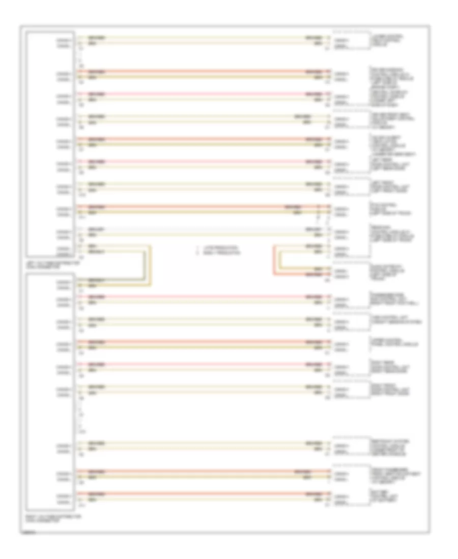
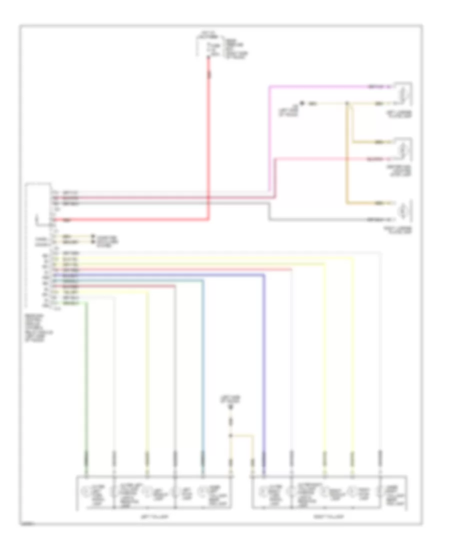
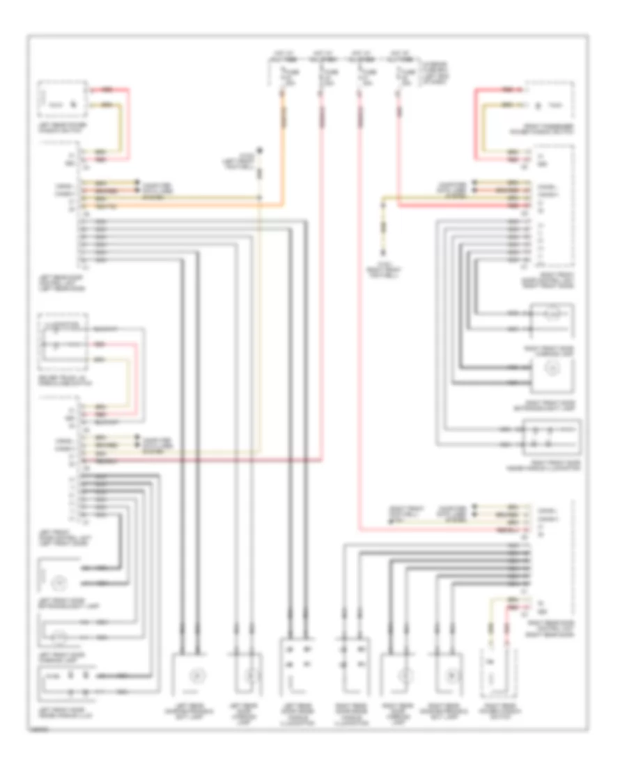
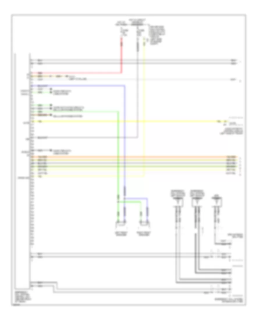
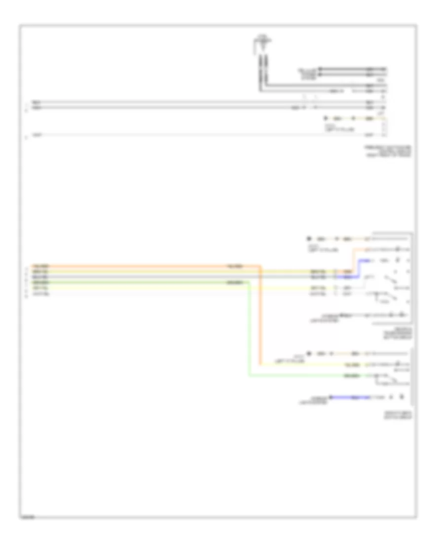
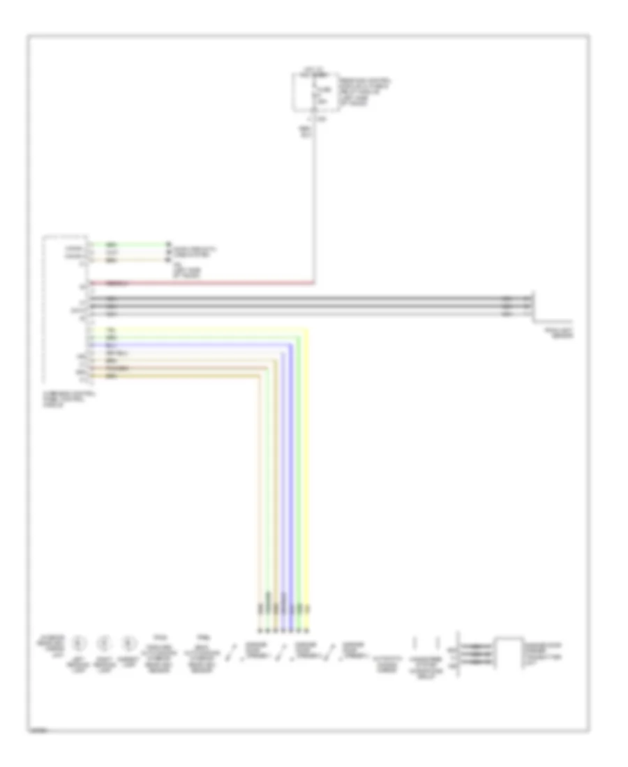
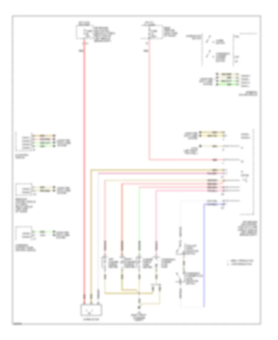
Automatic A/C Wiring Diagram (2 of 2) for Mercedes-Benz CLS500 2006
List of elements for Automatic A/C Wiring Diagram (2 of 2) for Mercedes-Benz CLS500 2006:
- (right front footwell)
- (right front footwell) w15/1
- (right front of engine compt)
- 58 re
- Can-b h
- Can-b l
- Can-ch
- Can-cl
- Circuit 58d potential splitter
- Computer data lines system
- Control panel rear switch group (4 zone ac)
- Coolant circulation pump (right front of engine compt)
- Coolant temperature sensor (right front of engine)
- Electric suction fan engine & ac w/integrated control (center front of engine compt)
- Engine controls system
- Front prefuse
- Fuse 150a
- Hot at all times
- In-car temperature sensor (left side of dash)
- Me-sfi (me) control unit (left rear of emgine compt)
- Passenger-side sam control module
- Red
- W15/1
- W2 (right front of engine compt)
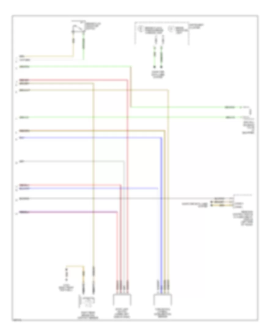
ANTI-LOCK BRAKES
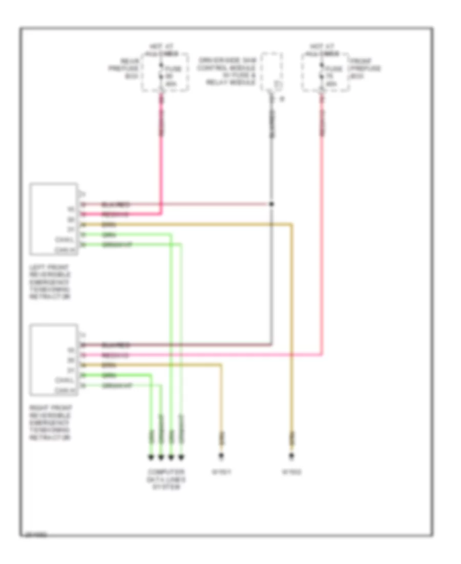
Anti-lock Brakes Wiring Diagram, Early Production (1 of 2) for Mercedes-Benz CLS500 2006
List of elements for Anti-lock Brakes Wiring Diagram, Early Production (1 of 2) for Mercedes-Benz CLS500 2006:
- 12v
- Brake fluid indicator switch
- Dfhl a a
- Dfhr a a
- Dfvl a a
- Dfvr a a
- Driver side sam control module w/ fuse & relay module (left side of engine compt)
- Front axle balance valve
- Front axle pre pressure sensor
- Front prefuse
- Fuse 40a
- Fuse 50a
- High pressure charging pump motor
- Hot at all times
- Left front inlet control valve
- Left front outlet control valve
- Left front pressure sensor
- Left front separation valve
- Left rear inlet control valve
- Left rear outlet control valve
- Left rear pressure sensor
- Left rear wheel speed sensor
- Nca
- Rear axle balance valve
- Rear sam control module w/ fuse & relay module (left side of trunk)
- Reservoir sensor
- Right front inlet control valve
- Right front outlet control valve
- Right front pressure sensor
- Right front separation valve
- Right rear inlet control valve
- Right rear outlet control valve
- Right rear pressure sensor
- Right rear wheel speed sensor
- Sbc control module
- Sbc pedal value sensor (left rear of engine compt)
- Solid state
- Traction system hydraulic unit
- W3/1 (right front of engine compt)
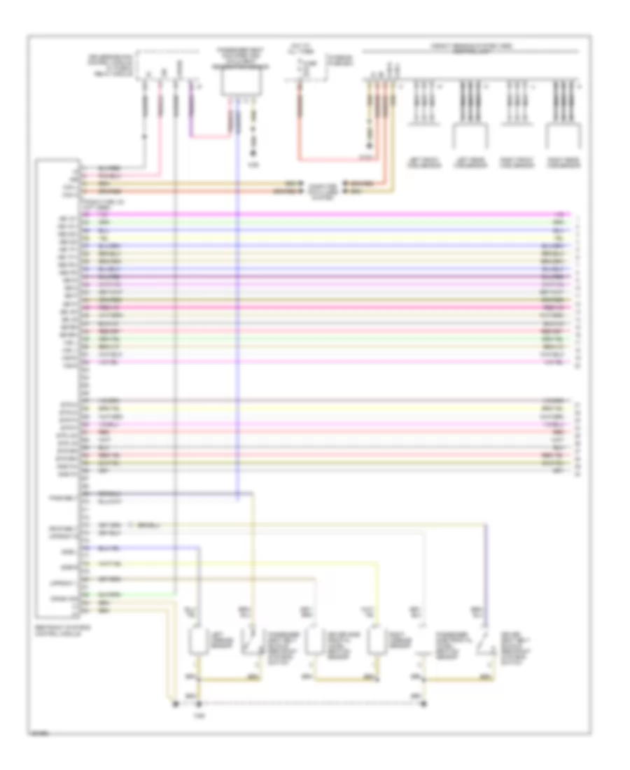
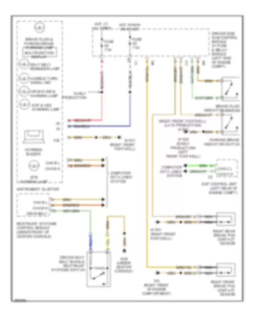
Anti-lock Brakes Wiring Diagram, Early Production (2 of 2) for Mercedes-Benz CLS500 2006
List of elements for Anti-lock Brakes Wiring Diagram, Early Production (2 of 2) for Mercedes-Benz CLS500 2006:
- (pin 15-28 not used)
- (pin 24-48 not used)
- Abs ind
- Brake fluid & parking brake warning lamp
- Brake indicator light
- Can h
- Can l
- Can-c h
- Can-c l
- Computer data lines system
- Data link connector (under left side of dash)
- Diag
- Driver side sam control module w/ fuse & relay module (left side of engine compt)
- Esp control unit (left rear of engine compt)
- Fuse 10a
- Fuse 20a
- Hot at all times
- Hot w/ circuit 87 relay energized
- I13
- Instrument cluster
- Left front wheel speed sensor
- Nca
- Pml (+)
- Pml (-)
- Right front brake pad contact sensor
- Right front wheel speed sensor
- Right rear brake pad contact sensor
- Solid state
- Sps (pml) solenoid valve
- Stop lamp switch (under left side of dash)
- Turn rate & lateral acceleration sensor
- W15/1 (right front footwell)
- W2 (right front of engine compt)
- W9 (left front of engine compt)
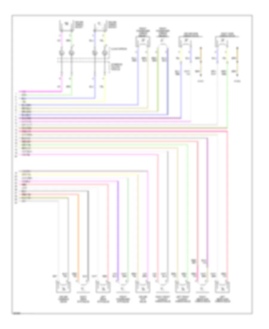
Anti-lock Brakes Wiring Diagram, Late Production (1 of 2) for Mercedes-Benz CLS500 2006
List of elements for Anti-lock Brakes Wiring Diagram, Late Production (1 of 2) for Mercedes-Benz CLS500 2006:
- (-)
- (left rear of engine compt) esp control unit
- (right front of engine compt) w3/1
- (under left side of dash) data link connector
- 12v
- Bla
- Bls
- Can-c h
- Can-c l
- Can-h h
- Can-h l
- Computer data lines system
- Df hl m
- Df hl s
- Df hr m
- Df hr s
- Df vl m
- Df vl s
- Df vr m
- Df vr s
- Diag
- Driver side sam control module w/ fuse & relay module (left side of engine compt)
- Front axle inlet solenoid valve
- Front axle pre pressure sensor
- Front axle switchover solenoid valve
- Front prefuse
- Fuse 40a
- High pressure charging pump motor
- Hot at all times
- I13
- Left front inlet control valve
- Left front outlet control valve
- Left front pressure sensor
- Left front wheel speed sensor
- Left rear inlet control valve
- Left rear outlet control valve
- Left rear pressure sensor
- Left rear wheel speed sensor
- Nca
- Pml 12v
- Pml a
- Rear axle switchover solenoid valve
- Right front brake pad contact sensor
- Right front inlet control valve
- Right front outlet control valve
- Right front pressure sensor
- Right front wheel speed sensor
- Right rear inlet control valve
- Right rear outlet control valve
- Right rear pressure sensor
- Right rear wheel speed sensor
- Solid state
- Traction system hydraulic unit
- W2 (right front of engine compt)
- W3/1 (right front of engine compt)
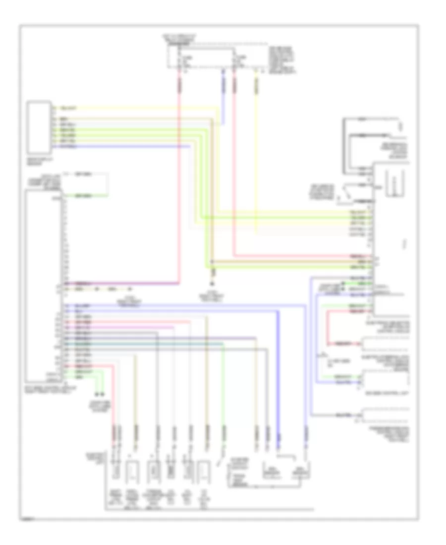
Anti-lock Brakes Wiring Diagram, Late Production (2 of 2) for Mercedes-Benz CLS500 2006
List of elements for Anti-lock Brakes Wiring Diagram, Late Production (2 of 2) for Mercedes-Benz CLS500 2006:
- Brake fluid & parking brake warning lamp
- Brake fluid indicator switch
- Brake indicator light
- Can-b h
- Can-b l
- Can-c h
- Can-c l
- Computer data lines system
- Instrument cluster
- Nca
- Rear sam control module w/ fuse & relay module (left side of trunk)
- Right rear brake pad contact sensor
- Sps (pml) solenoid valve (if equipped)
- Stop lamp switch (under left side of dash)
- Turn rate & lateral acceleration sensor
- W15/1 (right front footwell)
ANTI-THEFT
Anti-theft Wiring Diagram for Mercedes-Benz CLS500 2006
List of elements for Anti-theft Wiring Diagram for Mercedes-Benz CLS500 2006:
- Alarm signal siren
- Ata hood switch
- Ata inclination sensor
- Can-b h
- Can-b l
- Computer data lines system
- Fuse 200a
- Fuse 30a
- Fuse 7.5a
- Hot at all times
- Interior fuse box left end of dash)
- Ir rec
- Left front door control module (left front door)
- Left front ir receiver (left front door, door handle)
- Pawl rotary tumbler switch
- Rear prefuse (right side of trunk)
- Rear sam control module with fuse/ relay module (left side of trunk)
- Red
- Right front door control module
- Right front ir receiver
- Trunk lid external operation switch
- W15/1 (right front footwell)
- W6 (left side of trunk)
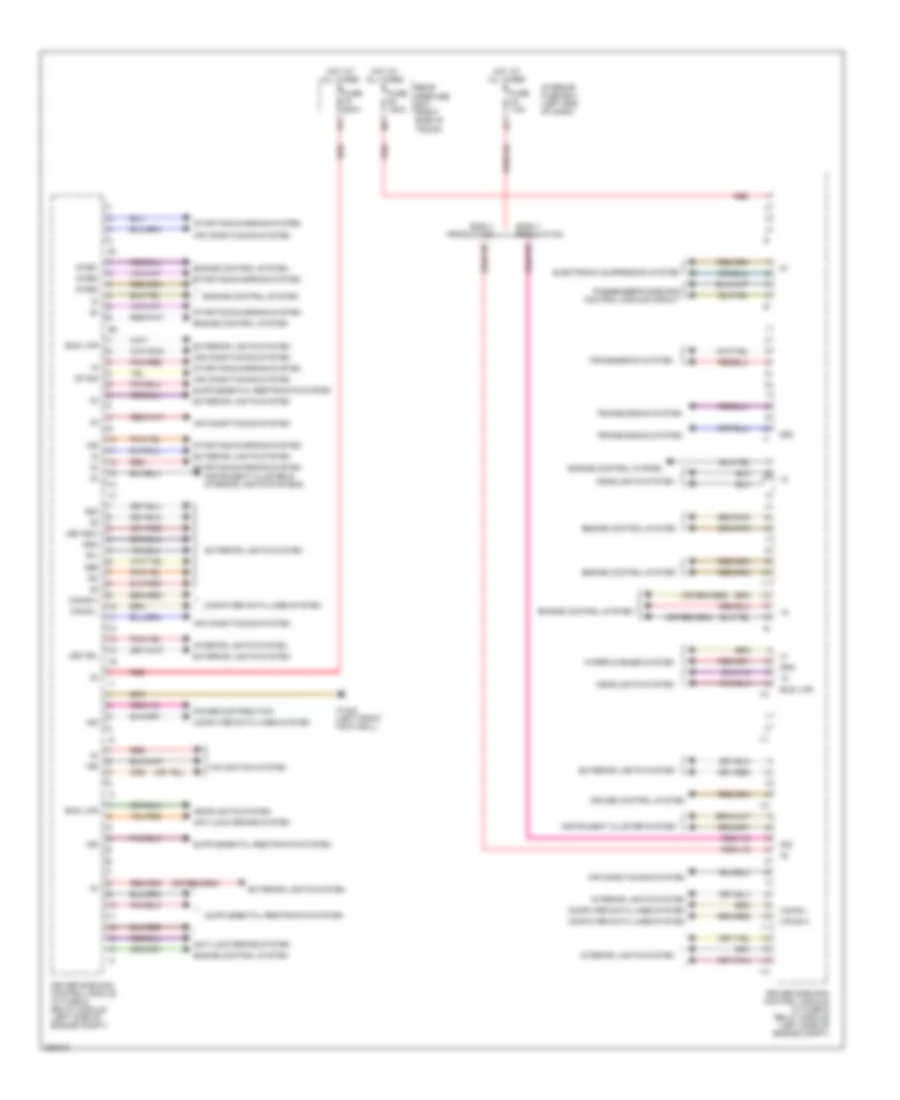
BODY CONTROL MODULES
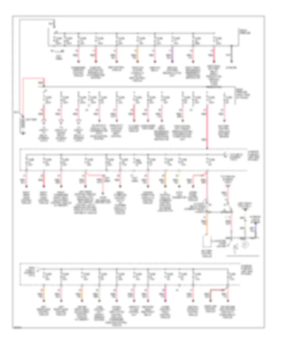
Driver"s Side SAM Control Module Wiring Diagram (1 of 2) for Mercedes-Benz CLS500 2006
List of elements for Driver"s Side SAM Control Module Wiring Diagram (1 of 2) for Mercedes-Benz CLS500 2006:
- 15g
- 15r
- 30z
- 56b
- 58d
- 87me1
- 87me2
- 87me3
- Afl
- Air conditioning system
- Anti-lock brake system
- Bus lwr
- Can-b h
- Can-b l
- Computer data lines system
- Cruise control system
- Df sig
- Driver side sam control module w/ fuse & relay module (left side of engine compt)
- Early production
- Electronic suspension system
- Engine control system
- Exterior lights system
- Fuse 150a
- Fuse 200a
- Fuse 7.5a
- Headlights system
- Hot at all times
- I10
- I11
- I12
- I13
- Instrument cluster & interior lights systems
- Instrument cluster system
- Interior fuse box (left end of dash)
- Interior lights system
- Led nsl
- Led nsw
- Navigation system
- Passenger's side sam control module circuit
- Pnk/red
- Power distribution
- Rear prefuse box (right side of trunk)
- Red
- Sra
- Starting/charging system
- Transmission system
- W15/2 (left front footwell)
- Wiper/washer system
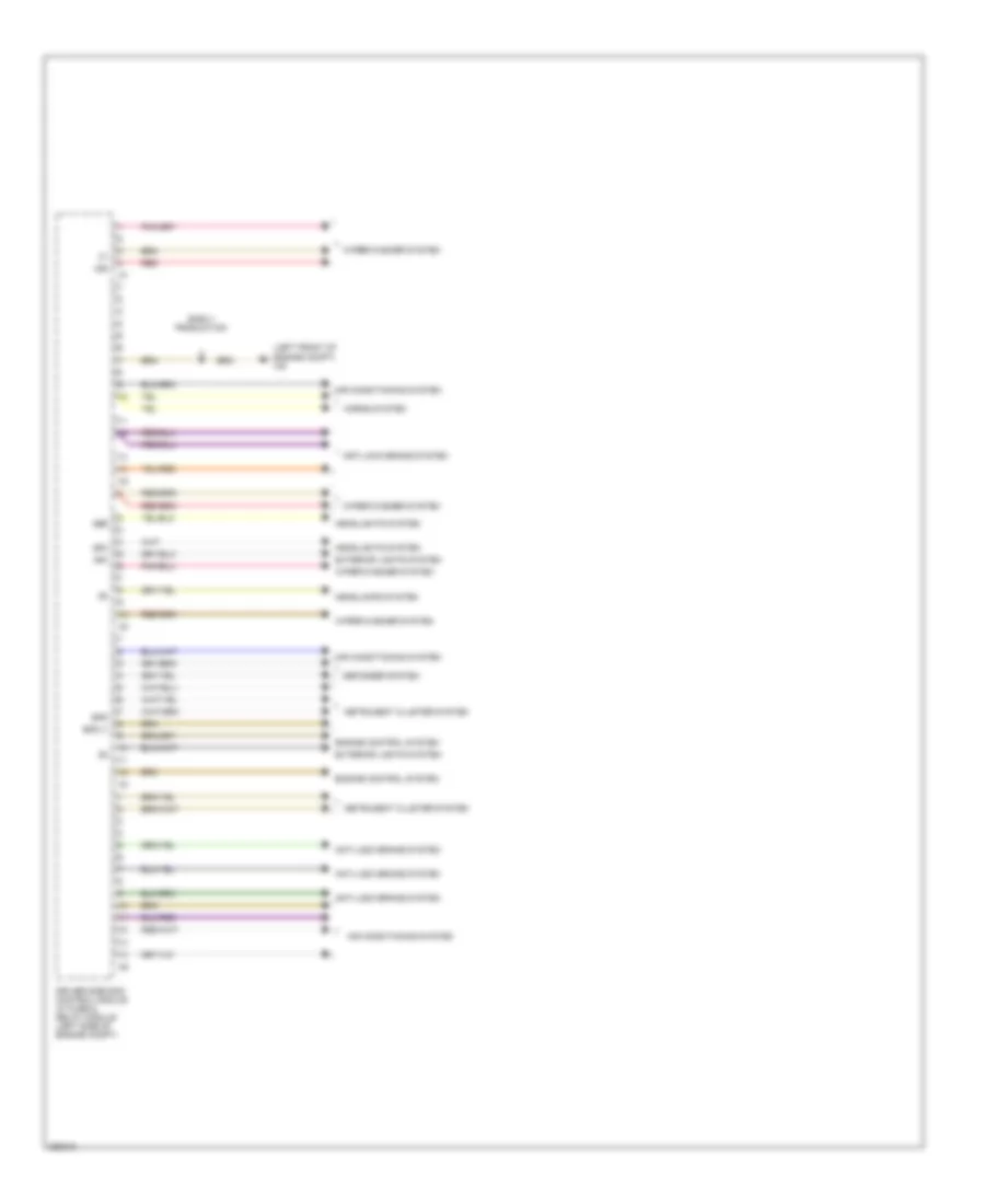
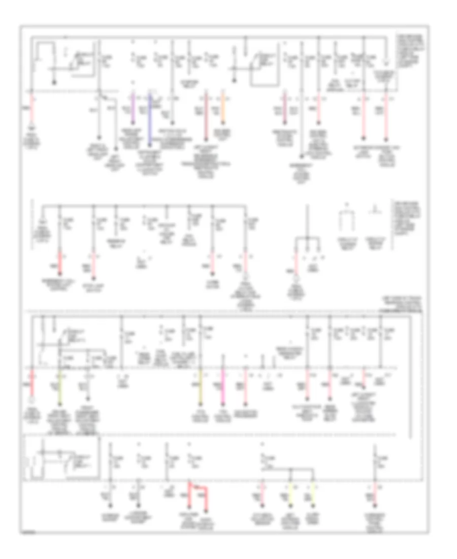
Driver"s Side SAM Control Module Wiring Diagram (2 of 2) for Mercedes-Benz CLS500 2006
List of elements for Driver"s Side SAM Control Module Wiring Diagram (2 of 2) for Mercedes-Benz CLS500 2006:
- (left front of engine compt) w9
- 15r
- 49a
- 56a
- 56b
- Air conditioning system
- Anti-lock brake system
- Bfs
- Bfs (-)
- Defogger system
- Driver side sam control module w/ fuse & relay module (left side of engine compt)
- Early production
- Engine control system
- Exterior lights system
- Headlamps system
- Headlights system
- Horns system
- Instrument cluster system
- Red
- Wiper/washer system
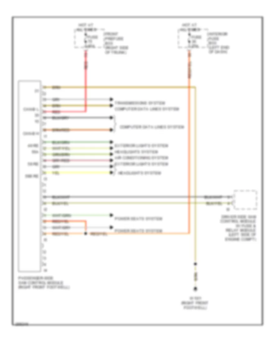
Passenger"s Side SAM Control Module Wiring Diagram for Mercedes-Benz CLS500 2006
List of elements for Passenger"s Side SAM Control Module Wiring Diagram for Mercedes-Benz CLS500 2006:
- 49 re
- 56a
- 56b re
- 58 re
- Air conditioning system
- Can-b h
- Can-b l
- Computer data lines system
- Driver side sam control module w/ fuse & relay module (left side of engine compt)
- Exterior lights system
- Front prefuse box (right side of trunk)
- Fuse 25a
- Fuse 40a
- Headlights system
- Hot at all times
- Interior fuse box (left end of dash)
- Passenger-side sam control module (right front footwell)
- Power seats system
- Red
- Transmissions system
- W15/1 (right front footwell)
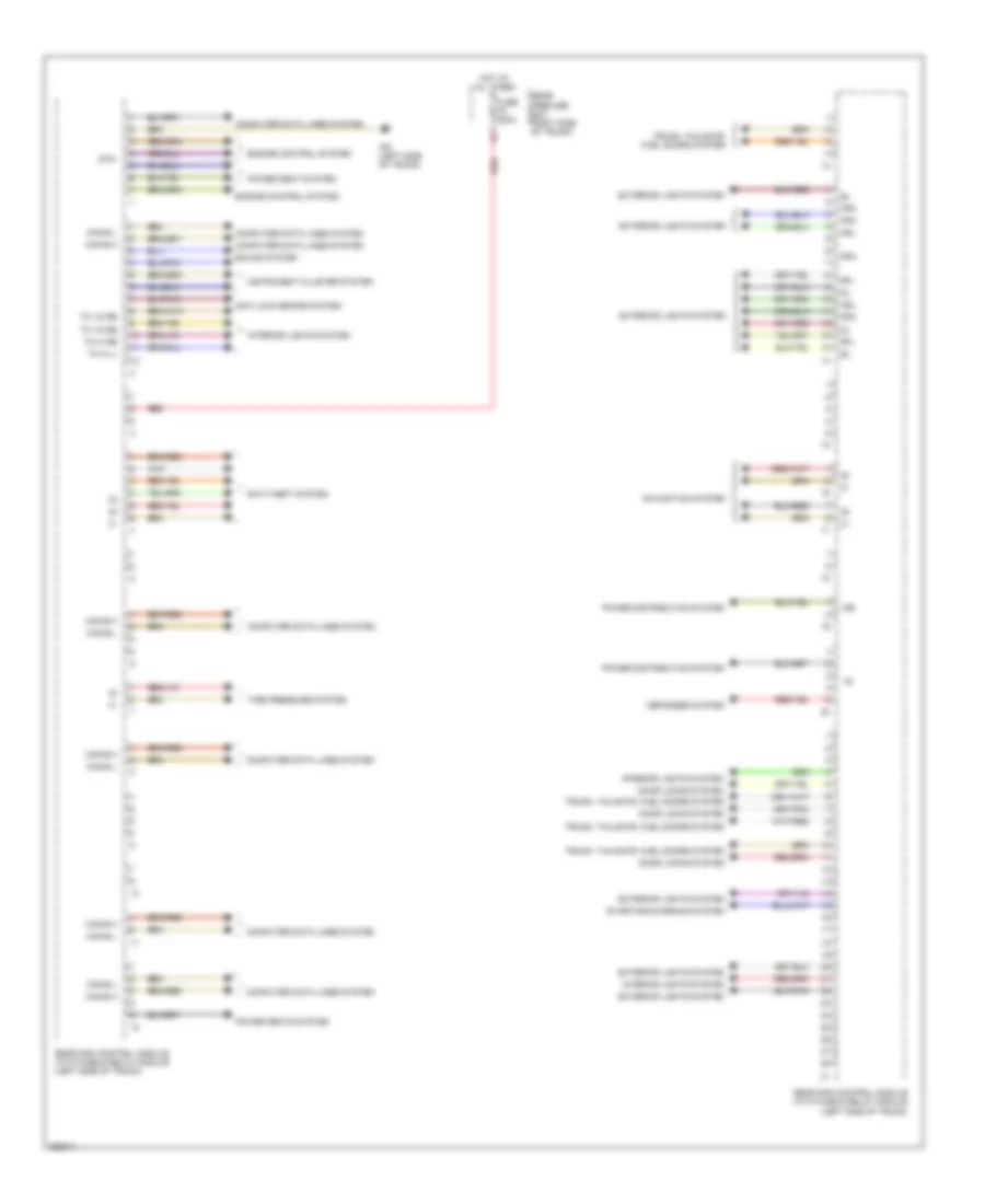
Rear SAM Control Module Wiring Diagram (1 of 2) for Mercedes-Benz CLS500 2006
List of elements for Rear SAM Control Module Wiring Diagram (1 of 2) for Mercedes-Benz CLS500 2006:
- 15r
- 87m1
- Anti-lock brake system
- Anti-theft system
- Can-b h
- Can-b l
- Computer data lines system
- Defogger system
- Door locks system
- Engine control system
- Exterior lights system
- Fra
- Fuse 200a
- Hot at all times
- Instrument cluster system
- Interior lights system
- Navigation system
- Nsl
- Power distribution system
- Power seat system
- Power seats system
- Rear prefuse box right side of trunk)
- Rear sam control module with fuse & relay module (left side of trunk)
- Red
- Rfl
- Sound system
- Starting/charging system
- Tire pressure system
- Tk hi li
- Tk hi re
- Tk vo re
- Trunk, tailgate, fuel doors system
- W6 (left side of trunk)
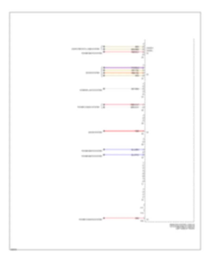
Rear SAM Control Module Wiring Diagram (2 of 2) for Mercedes-Benz CLS500 2006
List of elements for Rear SAM Control Module Wiring Diagram (2 of 2) for Mercedes-Benz CLS500 2006:
- Can-b h
- Can-b l
- Computer data lines system
- F17
- F18
- F20
- Interior lights system
- Power seats system
- Power window system
- Power windows system
- Rear sam control module with fuse & relay module (left side of trunk)
- Red
- Sound system
COMPUTER DATA LINES
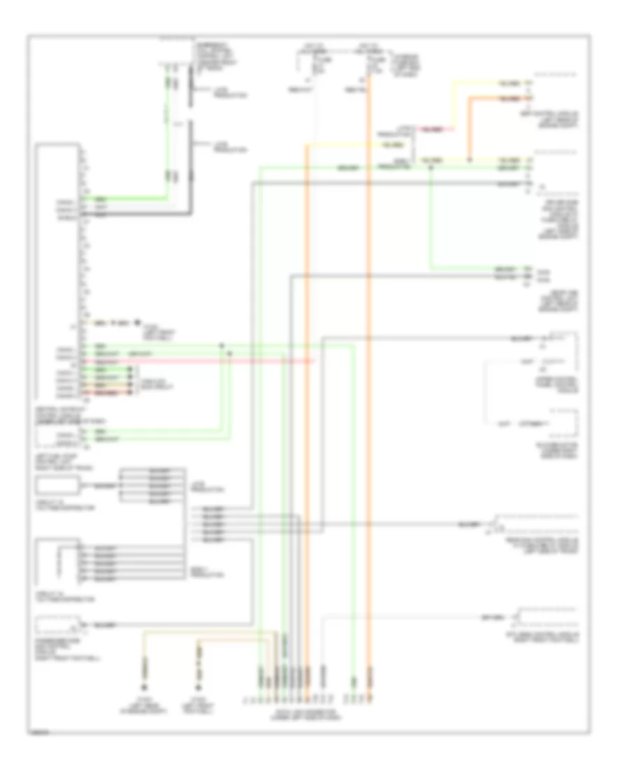
Data Link Connector Wiring Diagram for Mercedes-Benz CLS500 2006
List of elements for Data Link Connector Wiring Diagram for Mercedes-Benz CLS500 2006:
- Blower motor (under right side of dash)
- Can-b h
- Can-b l
- Can-c h
- Can-c l
- Can-d h
- Can-d l
- Central gateway control module (under left side of dash)
- Circuit 15 voltage distributor
- Data link connector (under left side of dash)
- Diag
- Driver side sam control module w/ fuse & relay module (left side of engine compt)
- Early production
- Emergency call system control unit (center front of trunk) c1
- Esp control module (left rear of engine compt)
- Etc (egs) control module (right front footwell)
- Fuse 5a
- Fuse 7.5a
- High/low bus circuit
- Hot at all times
- Interior fuse box (left end of dash)
- Late production
- Left fuel pump control unit (right side of trunk)
- Me-sfi (me) control unit (left rear of engine compt)
- Nca
- Passenger side sam control module (right front footwell)
- Rear sam control module w/ fuse & relay module (left side of trunk)
- Shield
- Upper control panel control module
- W15/2 (left front footwell)
- W15/3 (left rear of engine compt)
High/Low Bus Wiring Diagram (1 of 2) for Mercedes-Benz CLS500 2006
List of elements for High/Low Bus Wiring Diagram (1 of 2) for Mercedes-Benz CLS500 2006:
- Airmatic w/ ads control module (right front footwell)
- C10
- C11
- Can-b h
- Can-b l
- Can-c h
- Can-c l
- Central gateway control module (under left side of dash)
- Cockpit voltage distributor (can) connector
- Comfort aac pushbutton control module
- Driver side sam control module w/ fuse & relay module (left side of engine compt)
- Dtr control module
- Early production
- Eis (ezs) control unit
- Electronic control unit (vgs)
- Electronic selector lever module control module
- Esp control module (left rear of engine compt)
- Etc (egs) control module (right front footwell)
- Headlamp range adjustment control module (under front passenger's seat)
- Instrument cluster
- Late production
- Late production w/ reversible emergency tensioning retractor
- Late production w/o reversible emergency tensioning retractor
- Left voltage distributor (can) connector
- Me-sfi (me) control module (left rear of engine compt)
- Right front reversible emergency tensioning retractor
- Steering column module
- W/ 7 speed automatic transmission
- W/ reversible emergency tensioning retractor
- W/o 7 speed automatic transmission
- W15/2 (left front footwell)
High/Low Bus Wiring Diagram (2 of 2) for Mercedes-Benz CLS500 2006
List of elements for High/Low Bus Wiring Diagram (2 of 2) for Mercedes-Benz CLS500 2006:
- Audio gateway control module (left side of trunk)
- Battery control unit (at battery)
- C10
- C11
- Can-b h
- Can-b l
- Central gateway control module (under left side of dash)
- Driver front seat adjustment control module (w/ memory)
- Driver side sam control module w/ fuse & relay module (left side of engine compt)
- Early production
- Front passenger front seat adjustment control module (w/ memory)
- Hs (sih) & seat ventilation control module (w/ memory) (under driver's seat)
- I13
- Late production
- Left front door control unit (left front door)
- Left rear door control unit (left rear door)
- Left voltage distributor (can) connector
- Lower control field control module
- Passenger side sam control unit (right front footwell)
- Pts control module (left side of trunk)
- Rear sam control module w/ fuse & relay module (left side of trunk)
- Restraint system control module (under front of center console)
- Right front door control unit (right front door)
- Right rear door control unit (right rear door)
- Right voltage distributor (can) connector
- Upper control panel control module
- Wss control unit (weight sensing system)
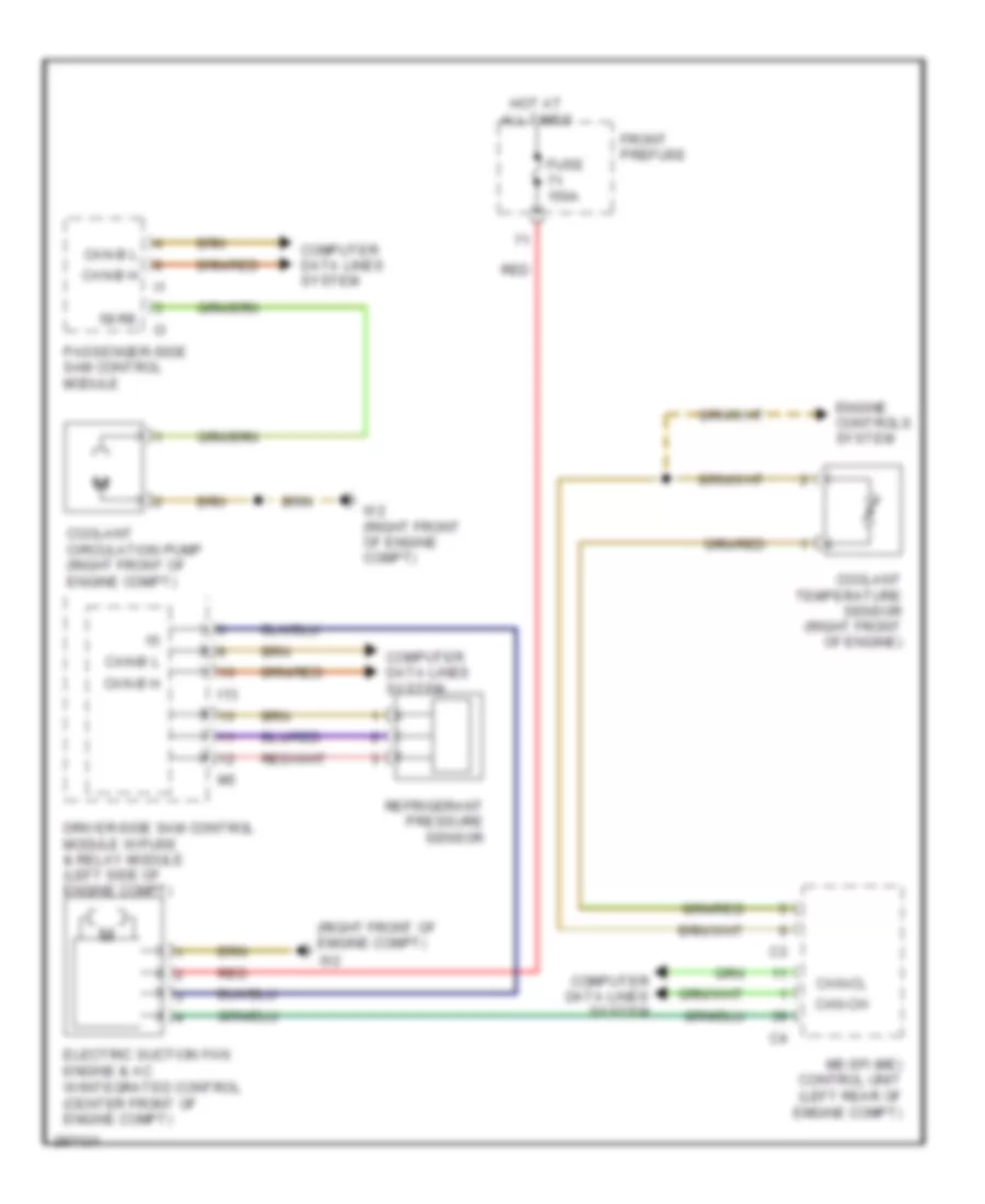
COOLING FAN
Cooling Fan Wiring Diagram for Mercedes-Benz CLS500 2006
List of elements for Cooling Fan Wiring Diagram for Mercedes-Benz CLS500 2006:
- (right front of emgine compt)
- 58 re
- Can-b h
- Can-b l
- Can-ch
- Can-cl
- Computer data lines system
- Coolant circulation pump (right front of engine compt)
- Coolant temperature sensor (right front of engine)
- Driver-side sam control module w/fuse & relay module (left side of engine compt)
- Electric suction fan engine & ac w/integrated control (center front of engine compt)
- Engine controls system
- Front prefuse
- Fuse 150a
- Hot at all times
- I13
- Me-sfi (me) control unit (left rear of emgine compt)
- Passenger-side sam control module
- Red
- Refrigerant pressure sensor
- W2 (right front of engine compt)
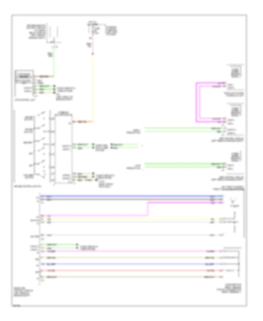
CRUISE CONTROL
Cruise Control Wiring Diagram for Mercedes-Benz CLS500 2006
List of elements for Cruise Control Wiring Diagram for Mercedes-Benz CLS500 2006:
- (not used)
- (on throttle body) throttle valve actuator
- Accelerator pedal sensor (top of accelerator pedal assembly)
- Can h
- Can l
- Can-b h
- Can-b l
- Can-c h
- Can-c l
- Computer data lines system
- Cruise control switch
- Cruise switch
- Dec/set
- Driver-side sam control module w/ fuse & relay module (left side of engine compt)
- Dtr control unit
- Dtr radar sensor
- Ea ip1s
- Ea ip2s
- Early production
- Esp control module (left rear of engine compt)
- Fuse 7.5a
- Hot at all times
- I12
- Interior fuse box (left end of dash)
- Late production
- Me-sfi (me) control module (left rear of engine compt)
- Off
- Sig
- Steering column module
- Traction system hydraulic unit
- Vcs (sbs) switch
- W15/1 (right front footwell)
- W9 (left front of engine compt)
- Wheel speed sensor signal
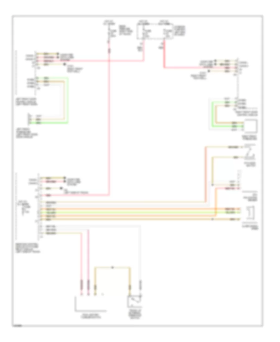
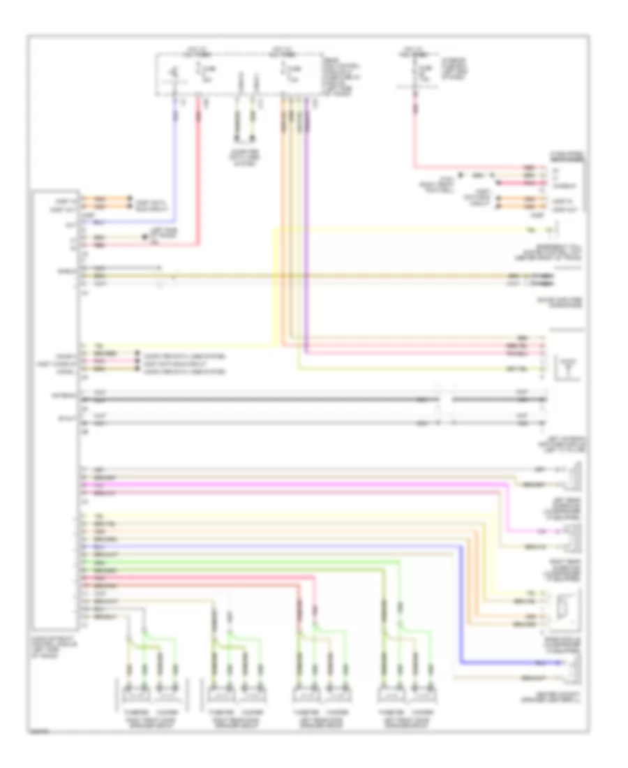
DEFOGGERS
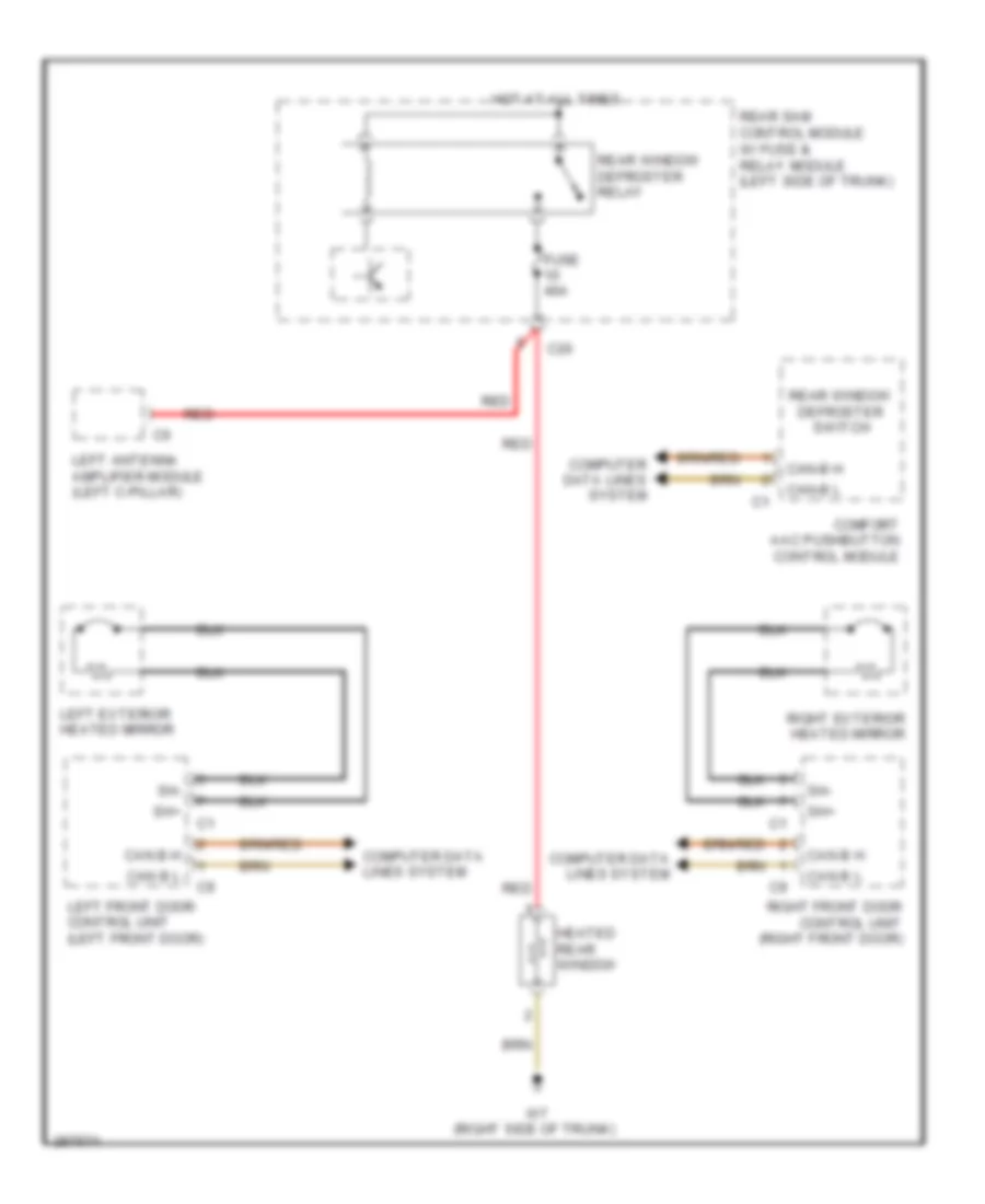
Defoggers Wiring Diagram for Mercedes-Benz CLS500 2006
List of elements for Defoggers Wiring Diagram for Mercedes-Benz CLS500 2006:
- C20
- Can b h
- Can b l
- Can-b h
- Can-b l
- Comfort aac pushbutton control module
- Computer data lines system
- Fuse 40a
- Heated rear window
- Hot at all times
- Left antenna amplifier module (left c-pillar)
- Left exterior heated mirror
- Left front door control unit (left front door)
- Rear sam control module w/ fuse & relay module (left side of trunk)
- Rear window defroster relay
- Rear window defroster switch
- Red
- Right exterior heated mirror
- Right front door control unit (right front door)
- Sh+
- Sh-
- W7 (right side of trunk)
ELECTRONIC SUSPENSION
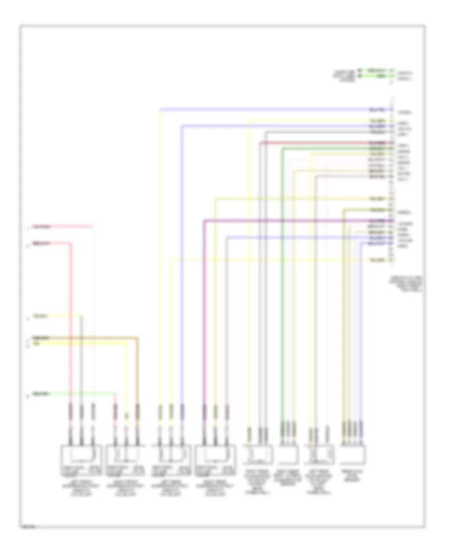
Electronic Suspension Wiring Diagram (1 of 2) for Mercedes-Benz CLS500 2006
List of elements for Electronic Suspension Wiring Diagram (1 of 2) for Mercedes-Benz CLS500 2006:
- (left front of engine compt) w9
- Airmatic central reservoir charge valve (under left front of vehicle)
- Airmatic compressor unit (under left front of vehicle)
- Airmatic pressure sensor
- Airmatic relay (s) (clipped on driver-side sam control module)
- Airmatic w/ ads control module (right front footwell)
- C37
- Ci6
- Driver side sam control module w/ fuse & relay module (left side of engine compt)
- Front prefuse
- Fuse 15a
- Fuse 40a
- Fuse 7.5a
- Hot at all times
- Hot w/ circuit 87 relay energized
- Interior fuse box (left end of dash)
- Left front axle damping valve unit (in left front wheelwell)
- Left front body lateral acceleration sensor
- Left front level sensor
- Nca
- Nvlm
- Nvls 1
- Nvls 2
- Nvlv
- Nvrm
- Nvrs 1
- Nvrs 2
- Nvrv
- Red
- Right front axle damping valve unit (in right front wheelwell)
- Right front body lateral acceleration sensor
- Right front level sensor
- Rkps
- Rkpv
- Val 1
- Val 2
- Valv
- Var 1
- Var 2
- Varv
- Vkps
- Vkpv
- Vsps
- Vvls
- Vvlv
- Vvrs
- Vzvsvl
- Vzvsvr
- Vzvvvl
- Vzvvvr
- W15/1 (right front footwell)
- Wake up
- Zamvl
- Zasvl
- Zavvl
- Zdspm
- Zdsps
- Zdspv
Electronic Suspension Wiring Diagram (2 of 2) for Mercedes-Benz CLS500 2006
List of elements for Electronic Suspension Wiring Diagram (2 of 2) for Mercedes-Benz CLS500 2006:
- Additional volume valve
- Airmatic w/ ads control module (right front footwell)
- Can-c h
- Can-c l
- Computer data lines system
- Hal 1
- Hal 2
- Hal v
- Har 1
- Har 2
- Har v
- Left front suspension strut airmatic valve unit
- Left rear axle damping valve unit (in left rear wheelwell)
- Left rear suspension strut airmatic valve unit
- Level valve
- Nca
- Nhrm
- Nhrs 1
- Nhrs 2
- Nhrv
- Rear axle level sensor
- Right front suspension strut airmatic valve unit
- Right rear axle damping valve unit (in right rear wheelwell)
- Right rear body lateral acceleration sensor
- Right rear suspension strut airmatic valve unit
- Vzvshl
- Vzvshr
- Vzvvhl
- Vzvvhr
- Zamhr
- Zashr
- Zavhr
ENGINE PERFORMANCE
5.0L
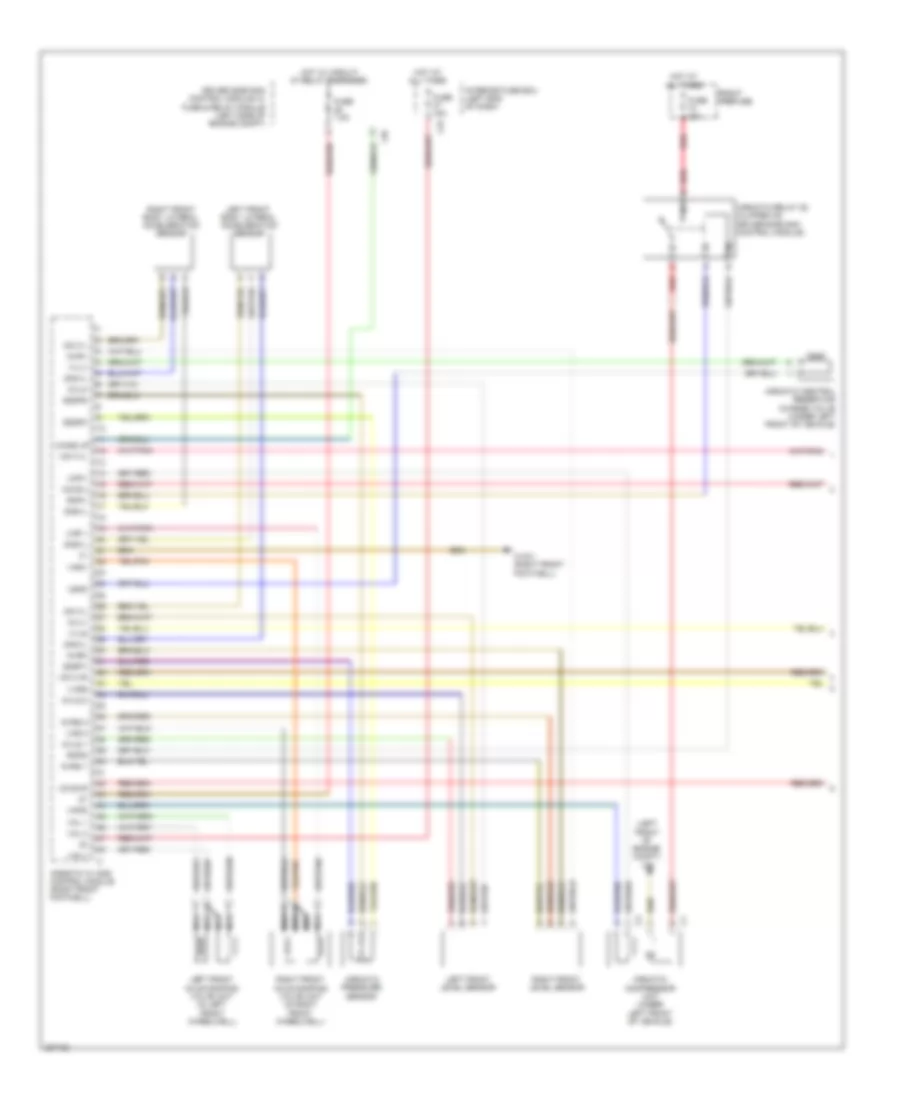
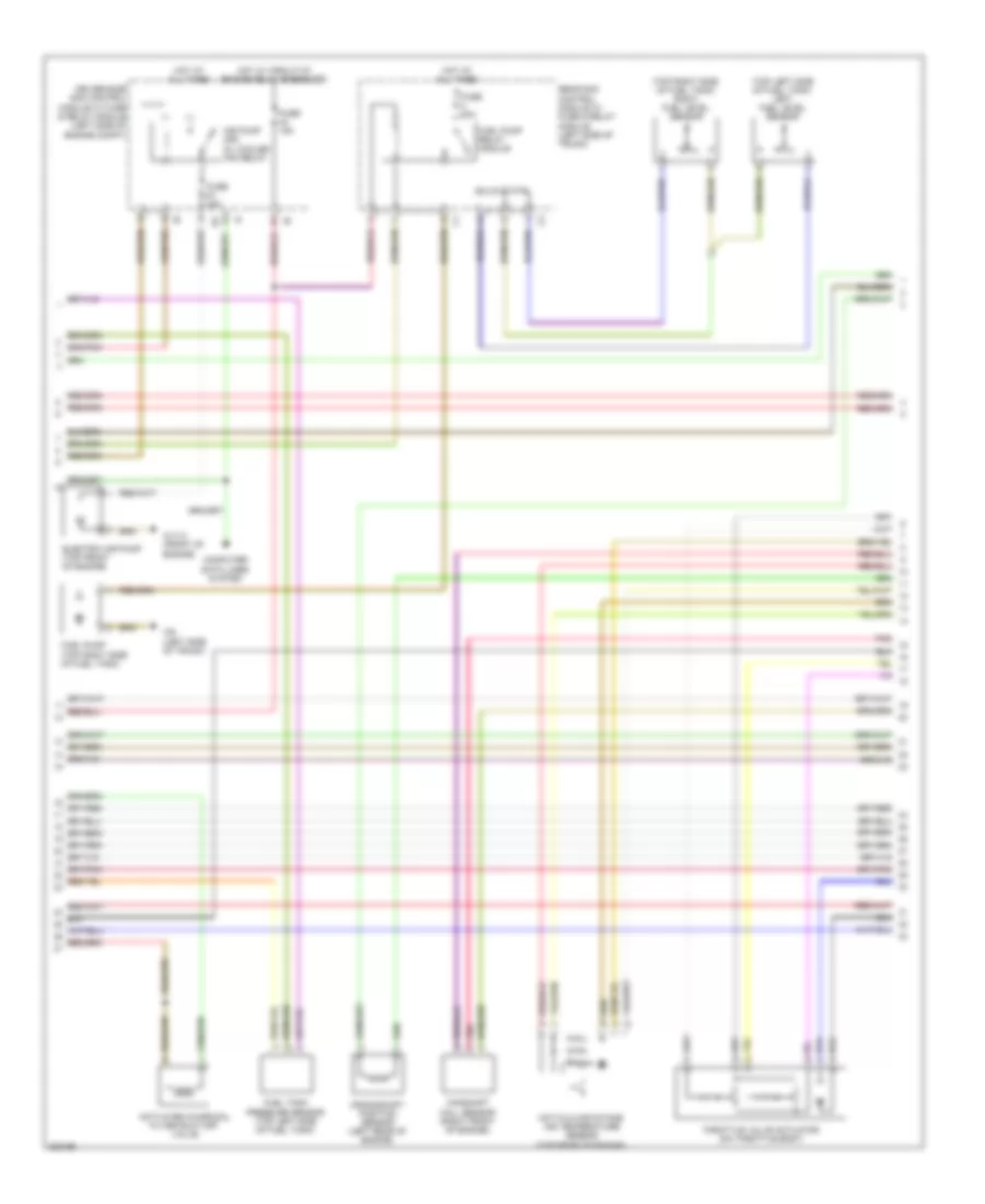
5.0L, Engine Performance Wiring Diagram (1 of 4) for Mercedes-Benz CLS500 2006
List of elements for 5.0L, Engine Performance Wiring Diagram (1 of 4) for Mercedes-Benz CLS500 2006:
- (-)
- 30z
- 87m1
- Aav
- Accelerator pedal sensor (top of accelerator pedal assembly)
- Computer data lines system
- Cooling fans system
- Diag
- Dst
- Ekpr
- Fuse 7.5a
- Hot at all times
- Interior fuse box (left end of dash)
- Left o2 sensor (downstream of twc) (in left exhaust, after twc)
- Left o2 sensor (upstream of twc) (in left exhaust, before twc)
- Ls nk m
- Ls1hk
- Ls2hk
- Lshhk1
- Lshhk2
- Lugs
- Me-sfi (me) control unit (left rear of engine compt)
- Nca
- Purge control valve
- Right o2 sensor (downstream of twc) (in right exhaust, after twc)
- Right o2 sensor (upstream of twc) (in right exhaust, before twc)
- Slpr
- Sp1m
- Sp1s
- Sp2m
- Sp2s
- Starting/charging system
- Str
- Tev
- Tna
- W15/3 (left rear of engine compt)
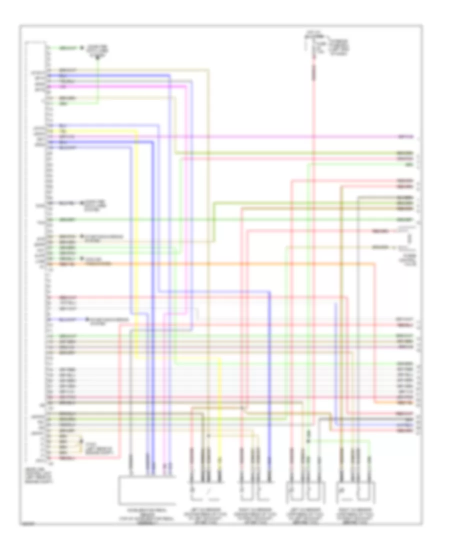
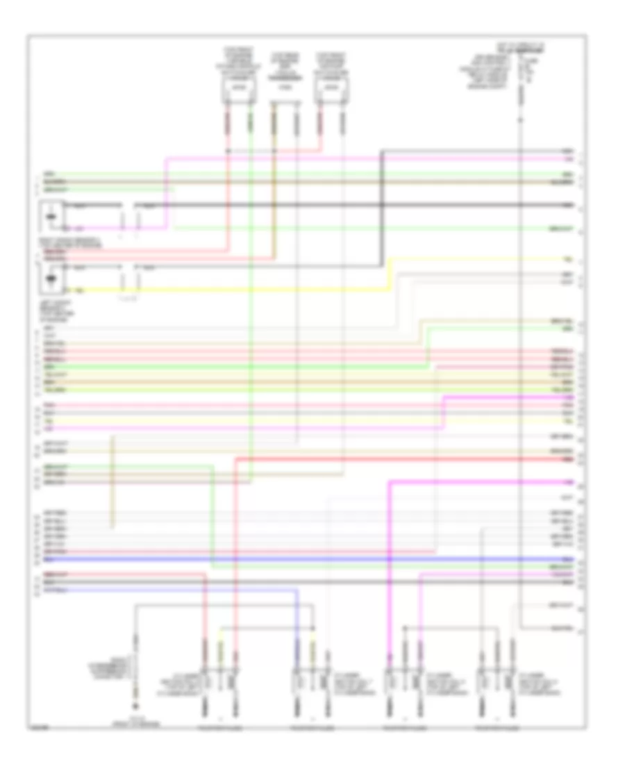
5.0L, Engine Performance Wiring Diagram (2 of 4) for Mercedes-Benz CLS500 2006
List of elements for 5.0L, Engine Performance Wiring Diagram (2 of 4) for Mercedes-Benz CLS500 2006:
- (top left side of fuel tank) left fuel level sensor
- (top right side of fuel tank) right fuel level sensor
- Activated charcoal filter shut-off valve
- Air pump (or) oil cooler fan relay
- Camshaft hall sensor (right front of engine)
- Computer data lines system
- Crankshaft position sensor (left rear of engine)
- Driver-side sam control module w/ fuse & relay module (left side of engine compt)
- Electric air pump (top front of engine)
- Fuel pump (top right side of fuel tank)
- Fuel pump relay module
- Fuel tank pressure sensor (top left side of fuel tank)
- Fuse 15a
- Fuse 20a
- Fuse 40a
- Hot at all times
- Hot film maf/intake air temperature sensor (top rear of engine)
- Hot w/ circuit 87 engine relay energized
- Pnk
- Rear sam control module w/ fuse & relay module (left side of trunk)
- Solid state
- Throttle valve actuator (on throttle body)
- W11/3 (front of engine)
- W6 (left side of trunk)
5.0L, Engine Performance Wiring Diagram (3 of 4) for Mercedes-Benz CLS500 2006
List of elements for 5.0L, Engine Performance Wiring Diagram (3 of 4) for Mercedes-Benz CLS500 2006:
- (top front of engine) air pump switchover valve
- (top front of engine) variable intake manifold switchover valve
- (top rear of engine) egr vacuum transducer
- Cylinder ignition coil 5 (top of left cylinder bank)
- Cylinder ignition coil 6 (top of left cylinder bank)
- Cylinder ignition coil 7 (top of left cylinder bank)
- Cylinder ignition coil 8 (top of left cylinder bank)
- Driver-side sam control module w/ fuse & relay module (left side of engine compt)
- Fuse 15a
- Hot w/ circuit 15 relay energized
- Left knock sensor 2 (top center of engine)
- Nca
- Pnk
- Radio interference suppression capacitor 1
- Red
- Right knock sensor 2 (top center of engine)
- To spark plugs
- W11/3 (front of engine)
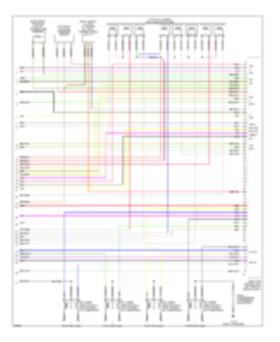
5.0L, Engine Performance Wiring Diagram (4 of 4) for Mercedes-Benz CLS500 2006
List of elements for 5.0L, Engine Performance Wiring Diagram (4 of 4) for Mercedes-Benz CLS500 2006:
- (-)
- (right front of engine) coolant temperature sensor
- (right side of oil pan) oil sensor (oil level, temperature & quality)
- (top front of engine) pressure sensor
- (top of cylinders) fuel injection valves
- +5v
- Ap mo+
- Ap mo-
- Cylinder ignition coil 1 (top of right cylinder bank)
- Cylinder ignition coil 2 (top of right cylinder bank)
- Cylinder ignition coil 3 (top of right cylinder bank)
- Cylinder ignition coil 4 (top of right cylinder bank)
- Ea ip1s
- Ea ip2s
- Ef a
- Ef b
- Me-sfi (me) control unit (left rear of engine compt)
- Mr ip
- Nca
- Pnk
- Radio interference suppression capacitor 2
- Red
- Sig
- To spark plugs
- Uref 2
- W11/3 (front of engine)
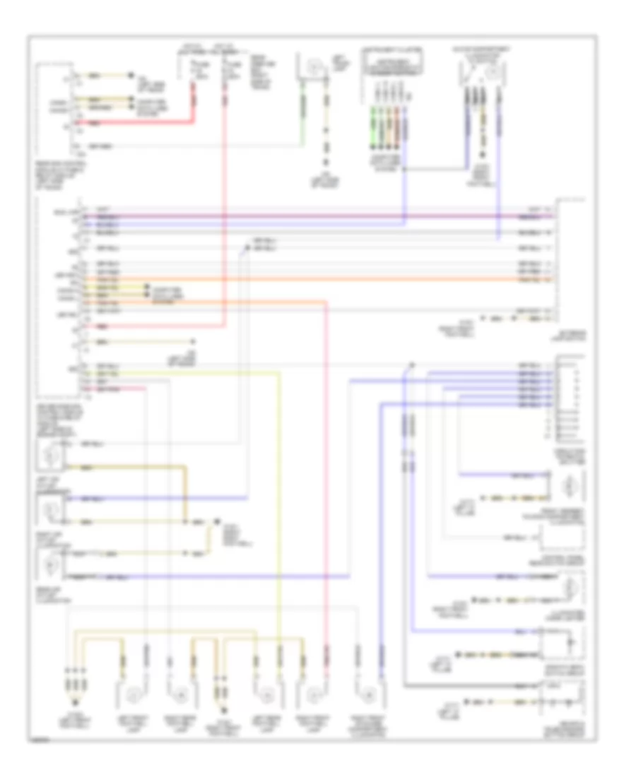
EXTERIOR LIGHTS
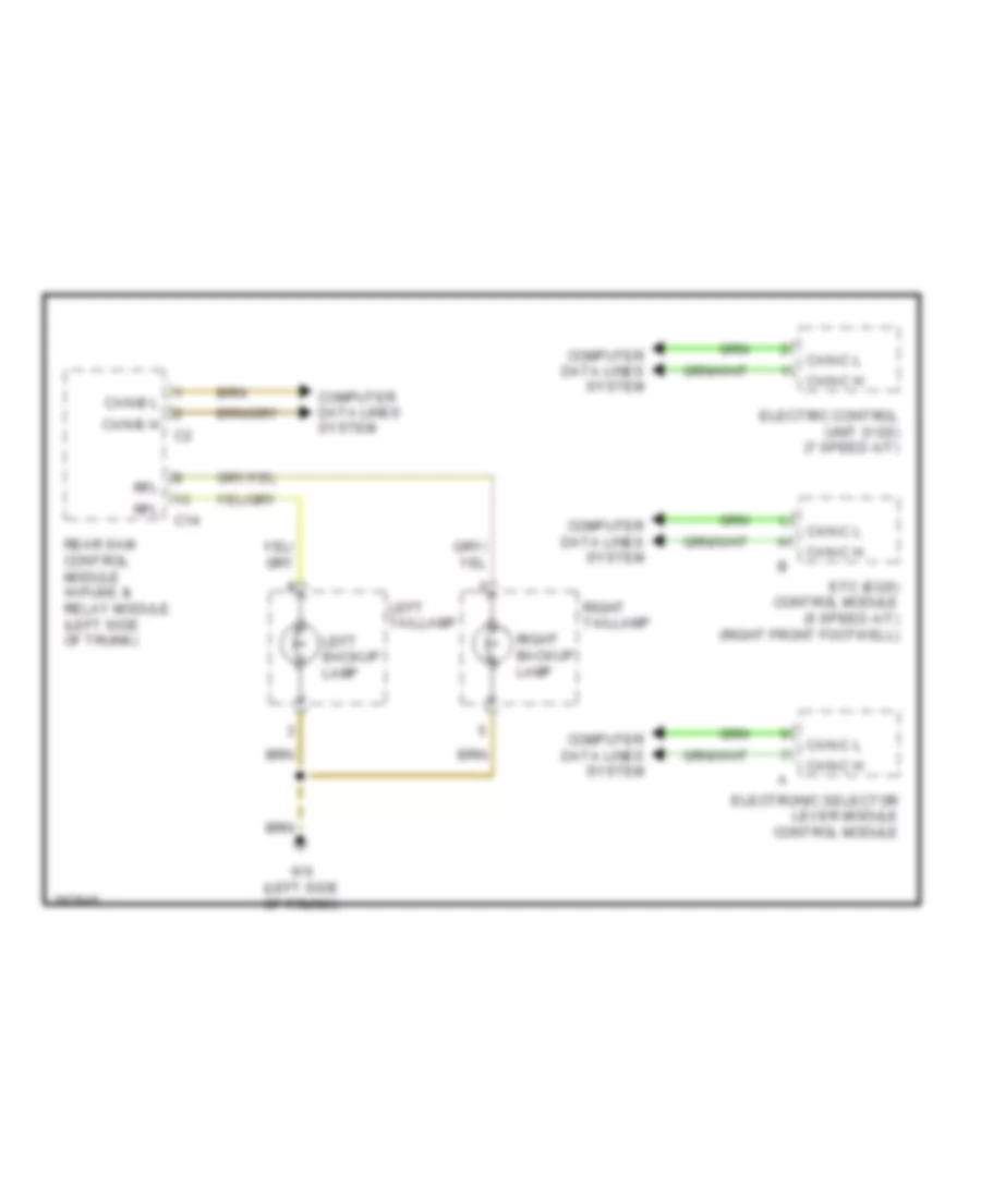
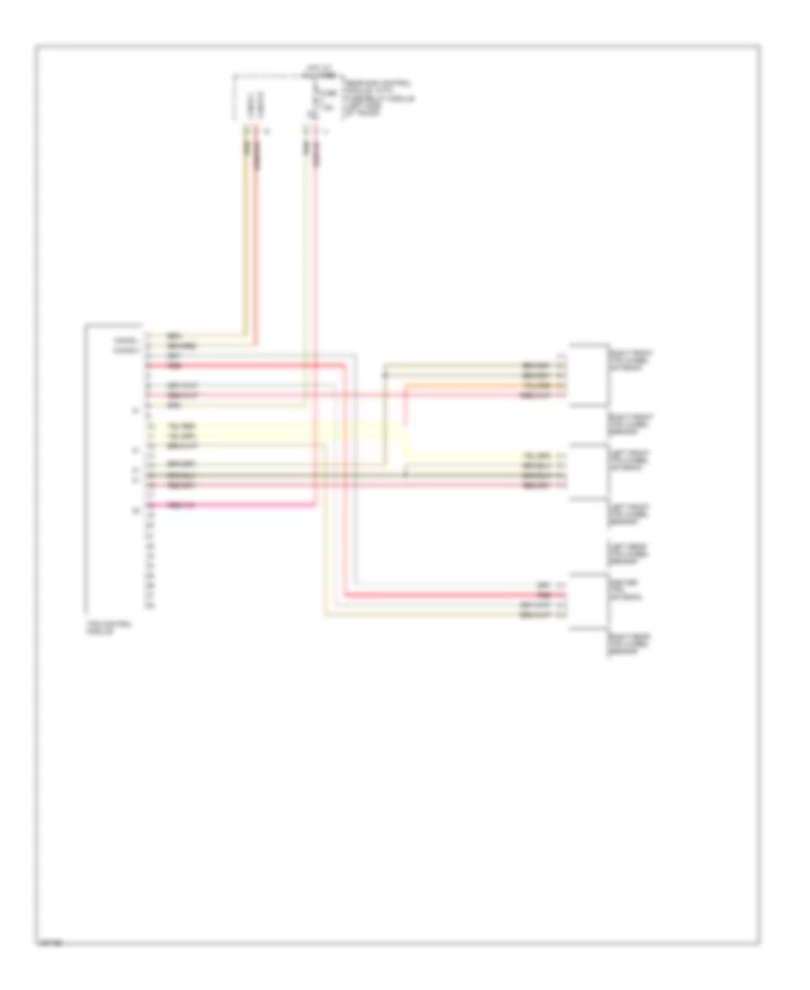
Back-up Lamps Wiring Diagram for Mercedes-Benz CLS500 2006
List of elements for Back-up Lamps Wiring Diagram for Mercedes-Benz CLS500 2006:
- C14
- Can-b h
- Can-b l
- Can-c h
- Can-c l
- Computer data lines system
- Electric control unit (vgs) (7 speed a/t)
- Electronic selector lever module control module
- Etc (egs) control module (5 speed a/t) (right front footwell)
- Left backup lamp
- Left taillamp
- Rear sam control module w/fuse & relay module (left side of trunk)
- Rfl
- Right backup lamp
- Right taillamp
- W6 (left side of trunk)
Front Exterior Lamps Wiring Diagram for Mercedes-Benz CLS500 2006
List of elements for Front Exterior Lamps Wiring Diagram for Mercedes-Benz CLS500 2006:
- 49 re
- 49a
- 56b
- 58 re
- 58d
- Afl
- Bls
- Bus lwr
- Can-b h
- Can-b l
- Can-c h
- Can-c l
- Combination switch
- Computer data lines system
- Driver-side sam control module w/fuse & relay module (left side of engine compt)
- Early
- Esp control unit (left rear of engine compt)
- Exterior lamp switch
- Fog lamp indicator lamp
- Fuse 10a
- Fuse 7.5a
- Hazard warning system switch
- Hcs (sra) switch
- Headlamp flasher/ high beam switch
- Hot at all times
- Instrument cluster
- Interior fuse box (left end of dash)
- Late production
- Led nsl
- Led nsw
- Left & right turn signal ind lamps, audible turn signal indicator
- Left & right turn signal switch
- Left electrically adjustable & heated exterior mirror
- Left exterior mirror turn signal lamp
- Left front door control unit (left front door)
- Left front headlamp unit
- Left outside mirror ambient lamp
- Left standing & parking lamp
- Left turn signal lamp
- Passenger-side sam control unit (right front footwell)
- Production
- Rear fog lamp indicator lamp
- Right electrically adjustable & heated exterior mirror
- Right exterior mirror turn signal lamp
- Right front door control unit (right front door)
- Right front headlamp unit
- Right outside mirror ambient lamp
- Right standing & parking lamp
- Right turn signal lamp
- Sra
- Standings lamp indicator lamp
- Steering column module
- Stop lamp switch (under left side of dash)
- Traction system hydraulic unit
- Ucp carrier motor limit switch
- Ucp carrier open & close motor
- Upper control panel control module
- W15/1 (right front footwell)
- W2 (right front of engine compt)
- W9 (left front of engine compt)
Rear Exterior Lamps Wiring Diagram for Mercedes-Benz CLS500 2006
List of elements for Rear Exterior Lamps Wiring Diagram for Mercedes-Benz CLS500 2006:
- (left side of trunk) w6
- C14
- C21
- Can-b h
- Can-b l
- Center high mounted stop lamp
- Computer data lines system
- Fra
- Fuse 200a
- Hot at all times
- Inner left taillamp, rear fog lamp
- Inner right taillamp, rear fog lamp
- Left backup lamp
- Left license plate lamp
- Left stop lamp
- Left taillamp
- Nsl
- Outer left taillamp, parking lamp & rear fog lamp
- Outer left turn signal lamp
- Outer right taillamp, parking lamp & rear fog lamp
- Outer right turn signal lamp
- Rear prefuse box (right side of trunk)
- Rear sam control module w/fuse & relay module (left side of trunk)
- Red
- Rfl
- Right backup lamp
- Right license plate lamp
- Right stop lamp
- Right taillamp
- W6 (left side of trunk)
GROUND DISTRIBUTION
Ground Distribution Wiring Diagram for Mercedes-Benz CLS500 2006
List of elements for Ground Distribution Wiring Diagram for Mercedes-Benz CLS500 2006:
- (7-speed a/t)
- (w/ memory)
- Air pump, radio interference suppression capacitor 1 & cylinder ignition coil (1 to 4)
- Airmatic compressor unit, air compressor motor, dtr control unit, driver-side sam control module w/ fuse & relay module,
- Battery control module & battery sensor
- Comand operating, display & control module, rear module keyless-go control unit, driver front seat adjustment control module, rear left door control module, hs (sih) & seat ventilation control module, right front backrest heated cushion, right front seat heated cushion, left front backrest heated cushion, left front seat heated cushion, left front reversible emergency tensioning retractor, left rear door keyless-go control unit, lower control field control module, driver-side sam control module w/ fuse & relay module, electronic selector lever module control module, neck-pro head restraint relay, gear display sensor, electric control unit (vgs), left voltage distributor (can) connector, left front door contact switch, left rear door contact switch, driver-side air bag squib, left rear footwell lamp, driver neck-pro head restraint solenoid, datalink connector, central gateway control module, left front footwell lamp, sdar antenna, left front door control module, right front stowage compartment illumination, illuminated cigar lighter & upper control panel control module,
- Data link connector
- Electric suction fan engine & ac w/ integrated control, right front headlamp unit, right fog lamp, coolant circulation pump, windshield washer fluid pump, left fanfare horn, right front brake pad contact sensor, c-aac sun sensor (4), washer nozzle heater, washer nozzle hose heater & c-aac (k-kla) multifunction sensor
- Esp control module, left front head lamp unit, left fog lamp, right fanfare horn, sdar antenna, c-aac (k-kla) multifunction sensor & left front brake pad contact sensor,
- Fuel pump
- Fuel pump, overhead control panel control module, audio gateway control module, rear sam control module w/ fuse & relay, rear screen blind relay, trunk lid keyless-go button, left trunk lamp, left tail lamp, right tail lamp, left rear head restraint motor, right rear head restraint motor, left rear door contact switch, overhead control panel & ffs (rba) connector, trunk lid ambient lamp, left license plate lamp, right license plate lamp, center high-mounted stop lamp, pawl rotary tumbler switch, trunk lid contact switch & trunk lid external operation switch
- Mb-info & telediagnosis button group, voice control system (vcs (sbs)) control unit, emergency call system control unit, universal portable ctel interface (upci (uhi)) control module, frequency switchover control module, sdar control unit & portable ctel antenna amplifier connector,
- Me-sfi (me) control module &
- Radio interference suppression capacitor 1,
- Radio interference suppression capacitor 2 & air pump
- Restraint systems control module
- Right rear door keyless-go control unit, front passenger front seat adjustment control module w/ memory, airmatic w/ ads control unit, right front reversible emergency tensioning retractor, heating systems recirculation unit, left air outlet illumination, right air outlet illumination, in car temperature sensor, glove compartment illumination w/ switch, right front footwell lamp, electric steering lock control module, instrument cluster, steering column module, headlamp range adjustment control module, right rear door control module, right front door control module, exterior lamp switch, eis (ezs) control unit, cd charger , electronic selector lever module control module, gear display sensor, etc (egs) control module, passenger-side sam control module, right front door contact switch, right rear door contact switch, right rear brake pad contact sensor, right side air bag ignition squib, right rear footwell lamp, front passenger neck-pro head restraint solenoid, wss control unit (weight sensing system), control panel rear switch group, rear air outlet illumination, upper control panel control module, illuminated cigar lighter, passenger-side sam control module, parking brake indicator switch & front armrest folding compartment illumination
- Sdar antenna,
- Sos/ata (edw) switch group,
- Tlc (hds) control module, luggage compartment socket, pneumatic pump for dynamic seat control & multicontour seat pneumatic pump
- Traction system hydraulic unit & esp control module
- W10 (right side of trunk)
- W11/3 (front of engine)
- W11w2 (right rear of engine)
- W15/1 (right front footwell)
- W15/2 (left front footwell)
- W15/3 (left rear of engine compt)
- W17/1 (left "c" pillar)
- W2 (right front of engine compt)
- W26 (under center console)
- W3/1 (right front of engine compt)
- W6 (left side of trunk)
- W6/1 (left side of trunk)
- W7 (right side of trunk)
- W9 (left front of engine compt)
HEADLIGHTS
Headlights Wiring Diagram for Mercedes-Benz CLS500 2006
List of elements for Headlights Wiring Diagram for Mercedes-Benz CLS500 2006:
- 55 re
- 56a
- 56b
- 56b re
- 58d
- Afl
- Alwr
- Bus lwr
- Can-b h
- Can-b l
- Can-c h
- Can-c l
- Combination switch
- Computer data lines system
- Driver-side sam control module w/fuse & relay module (left side of engine compt)
- Exterior lamp switch
- Fog lamp indicator lamp
- Fuse 7.5a
- Hcs (sra) switch
- Headlamp flasher/ high beam switch
- Headlamp range adjustment control module (under front passenger's seat)
- High beam indicator lamp
- Hot at all times
- Hra (lwr) power module
- I10
- Instrument cluster
- Interior fuse box (left end of dash)
- Led nsl
- Led nsw
- Left fog lamp
- Left front headlamp unit
- Left headlamp range adjustment motor
- Left high beam
- Left low beam
- Passenger-side sam control unit (right front footwell)
- Rear fog lamp indicator lamp
- Right fog lamp
- Right front headlamp unit
- Right headlamp range adjustment motor
- Right high beam
- Right low beam
- Sra
- Standings lamp indicator lamp
- Steering column module
- W/ xenon headlamps
- W15/1 (right front footwell)
- W2 (right front of engine compt)
- W9 (left front of engine compt)
- Xenon headlamp ignition module
- Xenon hra (lwr) power module
- Xenon left high beam solenoid
- Xenon right high beam solenoid
HORN
Horn Wiring Diagram for Mercedes-Benz CLS500 2006
List of elements for Horn Wiring Diagram for Mercedes-Benz CLS500 2006:
- (or nca)
- Can-b h
- Can-b l
- Can-c h
- Can-c l
- Computer data lines system
- Data
- Driver-side sam control module w/ fuse & relay module (left side of engine compt)
- Early production
- Fan relay module
- Fanfare horns and airbag clock spring contact
- Fanfare horns pushbutton
- Fuse 53a 15a
- Fuse 53b 15a
- Fuse 7.5a
- Hot at all times
- Hot w/ circuit 15r relay energized
- I13
- Interior fuse box (left end of dash)
- Left fanfare horn
- Left multifunction steering wheel pushbutton group
- Nca
- Red
- Right fanfare horn
- Steering column module
- Steering wheel gear shift signal processing module (inside steering wheel)
- Steering wheel heater electronics (if equipped)
- W/ steering wheel gear shifter
- W/o steering wheel gear shifter
- W15/1 (right front footwell)
- W2 (right front of engine compt)
- W9 (left front of engine compt)
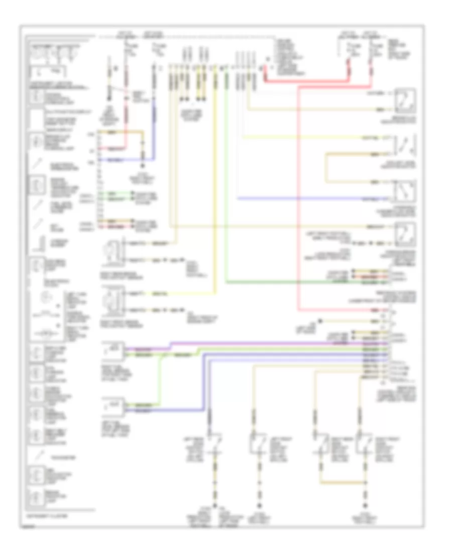
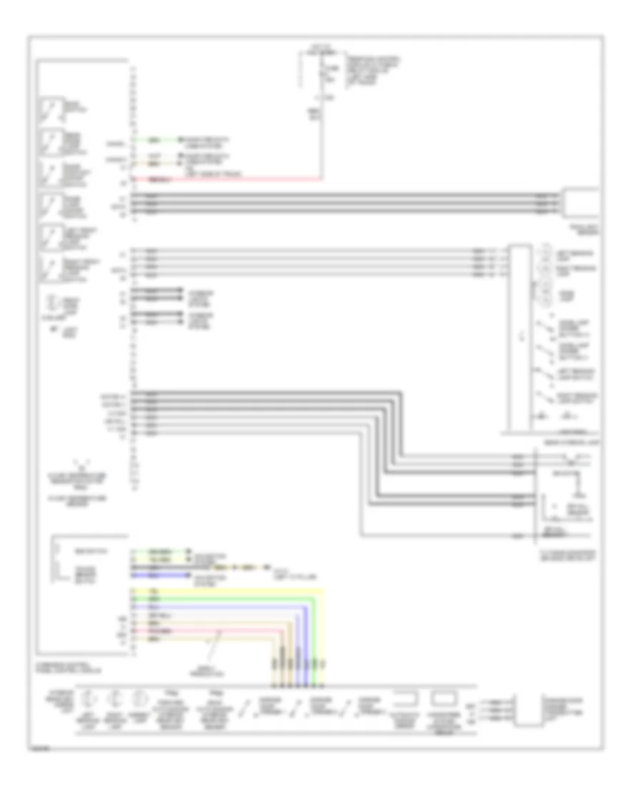
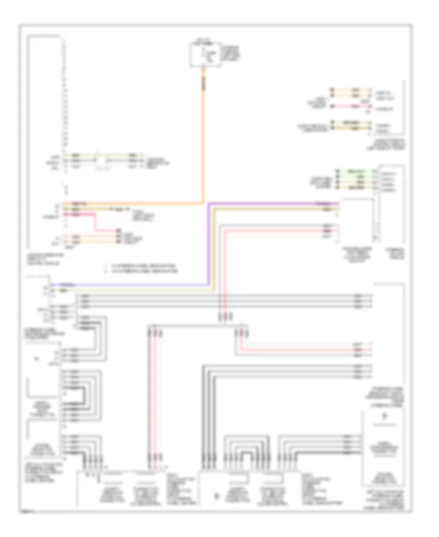
INSTRUMENT CLUSTER
Instrument Cluster Wiring Diagram for Mercedes-Benz CLS500 2006
List of elements for Instrument Cluster Wiring Diagram for Mercedes-Benz CLS500 2006:
- "check engine" malfunction indicator lamp
- (left front footwell) (early production) w15/2
- 15g
- 31e
- Abs malfunction indicator lamp
- Air bag indicator & warning lamp
- Audible turn signal indicator
- Brake fluid & parking brake warning lamp
- Brake fluid indicator switch
- Brake indicator lamp
- Can-b h
- Can-b l
- Can-c h
- Can-c l
- Computer data lines system
- Coolant level indicator switch
- Driver side sam control module w/ fuse & relay module (left side of engine compartment)
- Dtr warning lamp indicator
- Early pro- duction
- Ect gauge
- Electronic clock
- Electronic speedometer
- Engine coolant temperature malfunction indicator
- Esp & abs warning lamp indicator
- Fuel level & reserve gauge
- Fuel reserve indicator lamp
- Fuse 200a
- Fuse 7.5a
- Gear display
- High beam indicator lamp
- Hot at all times
- Hot in on or start
- I13
- Instrument cluster
- Instrument illumination
- Instrument lighting rheostat & reset button
- Left front door contact switch (on left b-pillar)
- Left fuel level sensor (top left side of fuel tank)
- Left rear door contact switch (on left c-pillar)
- Left turn signal indicator lamp
- Multifunction display
- Nca
- Parking brake indicator switch (left front footwell)
- Rear prefuse box (right side of trunk)
- Rear sam control module w/ fuse/relay module (left side of trunk)
- Red
- Restraint systems control module (under front of center console)
- Right front brake pad contact sensor
- Right front door contact switch (on right b-pillar)
- Right fuel level sensor (top right side of fuel tank)
- Right rear brake pad contact sensor
- Right rear door contact switch (on right c-pillar)
- Right turn signal indicator lamp
- Seat belt reminder lamp indicator
- Tachometer
- Tk hi li
- Tk hi re
- Tk vo li
- Tk vo re
- Trip odometer reset button
- W15/1 (late production) (right front footwell)
- W15/1 (right front footwell)
- W15/2 (early production) (left front footwell)
- W15/2 (left front footwell)
- W2 (right front of engine compt)
- W6 (late production) (left side of trunk)
- W6 (left side of trunk)
- W9 (left front of engine compt)
- Warning buzzer
- Windshield washer fluid level indicator switch
Overhead Console Wiring Diagram for Mercedes-Benz CLS500 2006
List of elements for Overhead Console Wiring Diagram for Mercedes-Benz CLS500 2006:
- (2 bulbs)
- 15r
- 58d
- Ambient lamp
- Automatic dimming mirror
- Back auto dimming interior rearview sensor
- C22
- Can-b h
- Can-b l
- Computer data lines system
- Data
- Dome lamp
- Dome lamp dimmer buttion (+)
- Dome lamp dimmer buttion (-)
- Dome lamp on/off switch
- Door
- Door contact on/off switch
- Early production
- Forward auto dimming interior rearview sensor
- Front dome lamp
- Fuse 25a
- Garage
- Garage door opener transmitter unit
- H 1 sig
- H 2 sig
- Hands-free system microphone group
- Hot at all times
- In car temperature sensor
- In car temperature sensor fan motor
- Interior lights system
- Interior rearview mirror unit
- Left front reading lamp switch
- Left reading lamp
- Left reading lamp switch
- Light ring
- Motor (+)
- Motor (-)
- Navigation system
- Nca
- Opener 1
- Opener 2
- Opener 3
- Overhead control panel control module
- Rain/light sensor
- Rear dome lamp switch
- Rear interior lamp
- Rear sam control module w/ fuse & relay module (left side of trunk)
- Right front reading lamp switch
- Right reading lamp
- Right reading lamp switch
- Roof switch
- Sos switch
- Sr hall sensor
- Sr hall sensor 1
- Sr motor
- Tilting/sliding roof (sr (shd)) drive unit
- Towing sensor switch
- Ub hall
- W17/1 (left "c" pillar)
- W6 (left side of trunk)
INTERIOR LIGHTS
Courtesy Lamps Wiring Diagram for Mercedes-Benz CLS500 2006
List of elements for Courtesy Lamps Wiring Diagram for Mercedes-Benz CLS500 2006:
- 15g
- 58d
- Bus lwr
- C24
- Can-b h
- Can-b l
- Can-c h
- Can-c l
- Circuit 58d potential splitter
- Computer data lines system
- Control panel rear switch group
- Driver side sam control module w/ fuse & relay module (left side of engine compt)
- Exterior lamp switch
- Front armrest folding compartment illumination
- Fuse 200a
- Glove compartment illumination w/ switch
- Hot at all times
- I13
- Illuminated cigar lighter
- Instrument cluster
- Instrument lighting rheostat & reset button
- Led nsl
- Led nsw
- Left air outlet illumination
- Left front footwell lamp
- Left rear footwell lamp
- Left trunk lamp
- Mb-info & telediagnosis button group
- Nca
- Rear air outlet illumination
- Rear prefuse box (right side of trunk)
- Rear sam control module w/ fuse & relay module (left side of trunk)
- Red
- Right air outlet illumination
- Right front footwell lamp
- Right front stowage compartment illumination
- Right rear footwell lamp
- Sos/ata (edw) switch group
- W15/1 (right front footwell)
- W15/1 (right right footwell)
- W15/2 (left front footwell)
- W17/1 (left "c" pillar)
- W6 (left side of trunk)
Instrument Illumination Wiring Diagram (1 of 2) for Mercedes-Benz CLS500 2006
List of elements for Instrument Illumination Wiring Diagram (1 of 2) for Mercedes-Benz CLS500 2006:
- C21
- C22
- Can-b h
- Can-b l
- Computer data lines system
- Data
- Dome lamp
- Dome lamp dimmer buttion (+)
- Dome lamp dimmer buttion (-)
- Dome lamp on/off switch
- Door contact on/off switch
- Front dome lamp
- Fuse 200a
- Hot at all times
- Left front door contact switch (on left b-pillar)
- Left front vanity mirror illumination
- Left front vanity mirror illumination switch
- Left reading lamp
- Left reading lamp switch
- Left rear door contact switch (on left c-pillar)
- Light ring
- Nca
- Overhead control panel control module
- Rain/light sensor
- Rear dome lamp switch
- Rear interior lamp
- Rear prefuse box (right side of trunk)
- Rear sam control module w/ fuse/ relay module (left side of trunk)
- Red
- Right front door contact switch (on right b-pillar)
- Right front vanity mirror illumination
- Right front vanity mirror illumination switch
- Right reading lamp
- Right reading lamp switch
- Right rear door contact switch (on right c-pillar)
- Tk hi li
- Tk hi re
- Tk vo li
- Tk vo re
- Trunk lid contact switch
- W15/1 (right front footwell)
- W15/2 (left front footwell)
- W6 (left side of trunk)
Instrument Illumination Wiring Diagram (2 of 2) for Mercedes-Benz CLS500 2006
List of elements for Instrument Illumination Wiring Diagram (2 of 2) for Mercedes-Benz CLS500 2006:
- (+)
- (-)
- (right front footwell) w15/1
- 58d
- Can-b h
- Can-b l
- Computer data lines system
- Driver trunk lid open/close switch
- Front passenger power window switch
- Fuse 30a
- Hot at all times
- Illumination
- Interior fuse box (left end of dash)
- Left front door control unit (left front door)
- Left front door entrance & exit lamp
- Left front door inside handle illum
- Left front door warning lamp
- Left rear door control unit (left rear door)
- Left rear door entrance & exit lamp
- Left rear door inside handle illumination
- Left rear door warning lamp
- Left rear power window switch
- Nca
- Red
- Right front door control unit (right front door)
- Right front door entrance & exit lamp
- Right front door inside handle illumination
- Right front door warning lamp
- Right rear door control unit (right rear door)
- Right rear door entrance & exit lamp
- Right rear door inside handle illumination
- Right rear door warning lamp
- Right rear power window switch
- W15/1 (right front footwell)
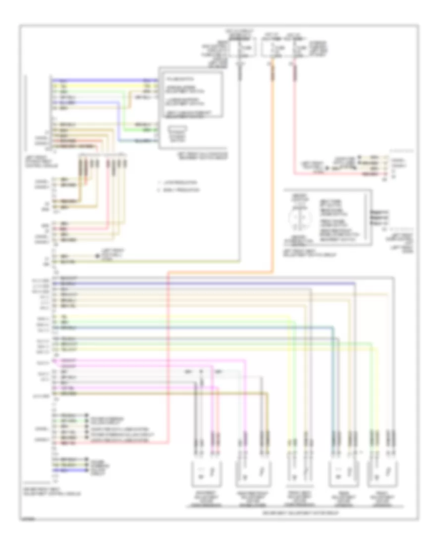
MEMORY SYSTEMS
Driver"s Memory Seat Wiring Diagram for Mercedes-Benz CLS500 2006
List of elements for Driver"s Memory Seat Wiring Diagram for Mercedes-Benz CLS500 2006:
- (left front footwell) w15/2
- (or red)
- - lumbar support adjustment switch
- - pulse switch
- - seat cushion fore/aft adjustment switch
- - side bolsters adjustment switch
- -backrest switch
- -front raise/ lower switch
- -head restraint raise/lower switch
- -rear raise/ lower switch
- -seat fore/ aft switch
- 15r
- Backrest adjustment motor (forward/back)
- C11
- Can-b h
- Can-b l
- Computer data lines system
- Driver front seat adjustment control module
- Driver seat adjustment motor group
- Dynamic
- Dynamic switch
- Early production
- Front adjustment motor (up/down)
- Front seat adjustment motor (forward/back)
- Fuse 30a
- Gnd
- Head restraint adjustment motor (raise/lower)
- Hh (+) sig
- Hh (-)
- Hot at all times
- Hot w/ circuit 15r relay 2 energized
- Hv (+) sig
- Hv (-)
- Interior fuse box (left end of dash)
- Late production
- Left front door control unit (left front door)
- Left front dynamic seat control module
- Left front multicontour backrest switch group
- Left front seat adjustment switch group
- Lk (+) sig
- Lk (-)
- Lv (+) sig
- Lv (-)
- Memory location 1, 2, 3 switch
- Memory store button switch
- Mhh (+)
- Mhh (-)
- Mhv (+)
- Mhv (-)
- Mlk (+)
- Mlk (-)
- Mlv (+)
- Mlv (-)
- Power steering column circuit
- Rear adjustment motor (up/down)
- Rear sam control module w/ fuse & relay module (left side of trunk)
- Red
Memory Mirrors Wiring Diagram for Mercedes-Benz CLS500 2006
List of elements for Memory Mirrors Wiring Diagram for Mercedes-Benz CLS500 2006:
- Automatic dimming mirror
- Can-b h
- Can-b l
- Computer data lines system
- Data
- Defogger system
- Exterior lights system
- Fold in/ fold out switch
- Fuse 30a
- Hot at all times
- In/out
- Interior fuse box (left end of dash)
- Left electrically adjustable & heated exterior mirror
- Left front door control unit (left front door)
- Left outside mirror ambient lamp
- Left turn signal
- Left/right switch
- Mirror heater
- Mirrors system
- Outside mirror adjustment switch
- Raise/lower, in/out switch
- Red
- Right electrically adjustable & heated exterior mirror
- Right front door control unit (right front door)
- Right outside mirror ambient lamp
- Right turn signal
- Up/down
- W15/1 (right front footwell)
- W15/2 (left front footwell)
Passenger"s Memory Seat Wiring Diagram for Mercedes-Benz CLS500 2006
List of elements for Passenger"s Memory Seat Wiring Diagram for Mercedes-Benz CLS500 2006:
- (or red)
- (right front footwell) w15/1
- - lumbar support adjustment switch
- - pulse switch
- - seat cushion fore/aft adjustment switch
- - side bolsters adjustment switch
- -backrest switch
- -front raise/ lower switch
- -head restraint raise/lower switch
- -rear raise/ lower switch
- -seat fore/ aft switch
- 15r
- Backrest adjustment motor (forward/back)
- C11
- Can-b h
- Can-b l
- Computer data lines system
- Dynamic
- Dynamic switch
- Early production
- Front adjustment motor (up/down)
- Front seat adjustment motor (forward/back)
- Fuse 30a
- Head restraint adjustment motor (raise/lower)
- Hh (+) sig
- Hh (-)
- Hot at all times
- Hot w/ circuit 15r relay 2 energized
- Hv (+) sig
- Hv (-)
- Interior fuse box (left end of dash)
- Late production
- Lk (+) sig
- Lk (-)
- Lv (+) sig
- Lv (-)
- Memory location 1, 2, 3 switch
- Memory store button switch
- Mhh (+)
- Mhh (-)
- Mhv (+)
- Mhv (-)
- Mlk (+)
- Mlk (-)
- Mlv (+)
- Mlv (-)
- Passenger front seat adjustment control module
- Passenger seat adjustment motor group
- Rear adjustment motor (up/down)
- Rear sam control module w/ fuse & relay module (left side of trunk)
- Red
- Right front door control unit (right front door)
- Right front dynamic seat control module
- Right front multicontour backrest switch group
- Right front seat adjustment switch group
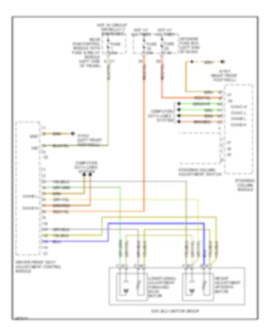
Steering Column Memory Wiring Diagram for Mercedes-Benz CLS500 2006
List of elements for Steering Column Memory Wiring Diagram for Mercedes-Benz CLS500 2006:
- 15r
- Can-b h
- Can-b l
- Can-c h
- Can-c l
- Column module
- Computer
- Computer data lines system
- Data lines
- Driver front seat adjustment control module
- Esc (elv) motor group
- Fuse 30a
- Fuse 7.5a
- Gnd
- Height adjustment up/down motor
- Hot at all times
- Hot w/ circuit 15r relay 2 energized
- Interior fuse box (left end of dash)
- Longitudinal adjustment forward/ back motor
- Rear sam control module with fuse & relay module (left side of trunk)
- Steering
- Steering column adjustment switch
- System
- W15/1 (right front footwell)
- W15/2 (left front footwell)
NAVIGATION
COMAND Actuation Wiring Diagram for Mercedes-Benz CLS500 2006
List of elements for COMAND Actuation Wiring Diagram for Mercedes-Benz CLS500 2006:
- Accept/ terminate phone call pushbutton
- Audio gateway control module (left side of trunk)
- Can-b h
- Can-b l
- Can-c h
- Can-c l
- Comand operating, display & control module
- Computer data lines system
- Data
- Fanfare horns and airbag clock spring contact
- Fuse 15a
- Hot at all times
- Interior fuse box (left end of dash)
- Left multifunction steering wheel pushbutton group (w/ steering wheel gear shifter)
- Left multifunction steering wheel pushbutton group (w/ steering wheel heater)
- Most
- Most data bus circuit
- Most in
- Most out
- Nca
- Nf-l
- Nf-r
- Out
- Pnk
- Pushbutton + & -, setting of specific function & volume control
- Red
- Right multifunction steering wheel pushbutton group (w/ steering wheel gear shifter)
- Right multifunction steering wheel pushbutton group (w/ steering wheel heater)
- Scroll forward/ back pushbutton
- Scroll forward/back pushbutton
- Separation point
- Shield
- Steering column module
- Steering wheel gear shift signal processing module (inside steering wheel)
- Steering wheel heater electronics (if equipped)
- System selection pushbutton
- W/ steering wheel gear shifter
- W/o steering wheel gear shifter
- W15/2 (left front footwell)
- Wake-up
- Walkman
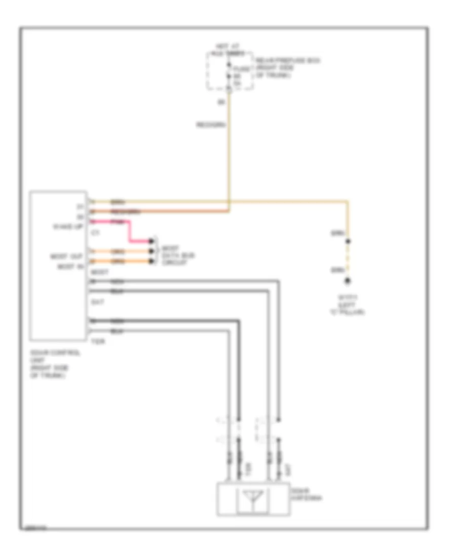
MOST Data Bus Wiring Diagram for Mercedes-Benz CLS500 2006
List of elements for MOST Data Bus Wiring Diagram for Mercedes-Benz CLS500 2006:
- (if equipped)
- Audio gateway control module (left side of trunk)
- Cd changer
- Comand operating, display & control module
- Most
- Navigation processor (left side of trunk)
- Out
- Pnk
- Sdar control unit (right side of trunk)
- Universal portable ctel interface (upci (uhi)) control module (center front of trunk)
- Voice control system (vcs (sbs)) control unit (right front of trunk)
- Wake-up
- Wake-up signal connector
Navigation Wiring Diagram for Mercedes-Benz CLS500 2006
List of elements for Navigation Wiring Diagram for Mercedes-Benz CLS500 2006:
- (if equipped)
- Audio gateway control module (left side of trunk)
- C16
- Can-b h
- Can-b l
- Can-c h
- Can-c l
- Cd changer
- Comand operating, display & control module
- Computer data lines system
- Di control module
- Emergency call system control unit (center front of trunk)
- Fuse 7.5a
- Gps
- Gps ant
- Gps antenna
- Gps antenna splitter
- Hot at all times
- Most
- Most in
- Most out
- Most wake-up
- Navigation processor (left side of trunk)
- Nca
- Out
- Pnk
- Rear sam control module w/ fuse & relay module (left side of trunk)
- Sdar control unit (right side of trunk)
- Shield
- Universal portable ctel interface (upci (uhi)) control module (center front of trunk)
- Voice control system (vcs (sbs)) control unit (right front of trunk)
- Wake-up
- Wake-up signal connector
Parktronic Wiring Diagram, Early Production for Mercedes-Benz CLS500 2006
List of elements for Parktronic Wiring Diagram, Early Production for Mercedes-Benz CLS500 2006:
- (+) sh
- (+) sv
- (-) sh
- (-) sv
- C17
- Can-b h
- Can-b l
- Computer data lines system
- Front bumper pts sensor unit
- Fuse 7.5a
- Hot at all times
- Left center sensor
- Left inner sensor
- Left outer sensor
- Lower control field control unit
- Pnk
- Pts control module (left side of trunk)
- Pts off switch
- Pts warning display (center of instrument panel)
- Rear bumper pts sensor unit
- Rear pts warning display
- Rear sam control module w/ fuse & relay module (left side of trunk)
- Right center sensor
- Right inner sensor
- Right outer sensor
- S1 v
- S10 h
- S2 v
- S3 v
- S4 v
- S5 v
- S6 v
- S7 h
- S8 h
- S9 h
- W h (+)
- W h (-)
- W h (data)
- W v (+)
- W v (-)
- W v (data)
Parktronic Wiring Diagram, Late Production for Mercedes-Benz CLS500 2006
List of elements for Parktronic Wiring Diagram, Late Production for Mercedes-Benz CLS500 2006:
- (+) sh
- (+) sv
- (-) sh
- (-) sv
- Can-b h
- Can-b l
- Center left front pts ultrasonic sensor
- Center right front pts ultrasonic sensor
- Computer data lines system
- Fuse 7.5a
- Hot at all times
- Inner left front pts ultrasonic sensor
- Inner left rear pts ultrasonic sensor
- Inner right front pts ultrasonic sensor
- Inner right rear pts ultrasonic sensor
- Lower control field control unit
- Outer left front pts ultrasonic sensor
- Outer left rear pts ultrasonic sensor
- Outer right front pts ultrasonic sensor
- Outer right rear pts ultrasonic sensor
- Pnk
- Pts control module (left side of trunk)
- Pts off switch
- Pts warning display (center of instrument panel)
- Rear pts warning display
- Rear sam control module w/ fuse & relay module (left side of trunk)
- S1 v
- S10 h
- S2 v
- S3 v
- S4 v
- S5 v
- S6 v
- S7 h
- S8 h
- S9 h
- W h (+)
- W h (-)
- W h (data)
- W v (+)
- W v (-)
- W v (data)
Tele Aid Wiring Diagram (1 of 2) for Mercedes-Benz CLS500 2006
List of elements for Tele Aid Wiring Diagram (1 of 2) for Mercedes-Benz CLS500 2006:
- 15r
- Audio gateway control module (left side of trunk)
- Can-d h
- Can-d l
- Cellular phones system
- Ci3
- Computer data lines system
- Crash sig
- Driver side sam control module with fuse & relay module (left side of engine compt)
- Emergency call system antenna splitter
- Emergency call system control unit (center front of trunk)
- Emergency call system left backup antenna
- Fuse 5a
- Fuse 7.5a
- Gps antenna
- Gps antenna splitter
- Hot at all times
- Hot w/ circuit 15r relay energizer
- Left front speaker
- Mute
- Nca
- Red
- Right front speaker
- S nca
- Shield
- Voice activation circuit & cellular phones system
- W17/1 (left "c" pillar)
Tele Aid Wiring Diagram (2 of 2) for Mercedes-Benz CLS500 2006
List of elements for Tele Aid Wiring Diagram (2 of 2) for Mercedes-Benz CLS500 2006:
- Cellular phones system
- Ctel antenna
- Frequency switchover control module (right front of trunk)
- Interior lights system
- Kom
- Lct
- Mb-info & telediagnosis button group
- Nca
- S nca
- Sos/ata (edw) switch group
- W17/1 (left "c" pillar)
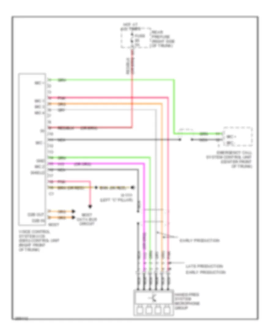
Voice Activation Wiring Diagram for Mercedes-Benz CLS500 2006
List of elements for Voice Activation Wiring Diagram for Mercedes-Benz CLS500 2006:
- (or red)
- D2b in
- D2b out
- Early production
- Emergency call system control unit (center front of trunk)
- Fuse 5a
- Gnd
- Hands-free system microphone group
- Hot at all times
- Late production
- Mic +
- Mic -
- Mic 1
- Mic 2
- Mic 3
- Mic 4
- Most
- Most data bus circuit
- Nca
- Pnk
- Rear prefuse (right side of trunk)
- Shield
- Voice control system (vcs (sbs)) control unit (right front of trunk)
- W17/1 (left "c" pillar)
POWER DISTRIBUTION
Power Distribution Wiring Diagram (1 of 2) for Mercedes-Benz CLS500 2006
List of elements for Power Distribution Wiring Diagram (1 of 2) for Mercedes-Benz CLS500 2006:
- (diagram 1 of 2)
- (left front footwell) w15/2
- (not used)
- (right side of trunk)
- 87a
- Additional battery relay (early production) terminal block (late production)
- Airmatic relay
- Airmatic w/ ads control unit
- Battery
- Battery control module
- Battery control module & battery sensor
- Central gateway control module
- Comand operating, display & control module
- Cutoff relay for interruptible loads
- Data link connector
- Di control module, steering control module & exterior lamp switch
- Door keyless-go control unit
- Driver front seat adjustment control module (w/ memory)
- Driver side sam control module w/ fuse & relay module
- Electric suction fan engine & a/c w/ integrated control
- Esp control module
- From fuse 31 a
- Front passenger front seat adjustment control module (w/ memory)
- Front prefuse
- Fuse
- Fuse 150a
- Fuse 15a
- Fuse 200a
- Fuse 20a
- Fuse 25a
- Fuse 30a
- Fuse 40a
- Fuse 50a
- Fuse 5a
- Fuse 7.5a
- Fuse res
- Heating systems recirculation unit
- Hs (sih) & seat ventilation control module & passenger side sam control module
- Illuminated cigar lighter
- Interior fuse box (left end of dash)
- Interior lights system
- Left front door control module
- Left front reversible emergency tensioning retractor
- Left rear door control module
- Left rear door keyless-go control unit, rear module keyless-go control unit & rear sam control module with fuse and relay module
- Lower control field control module
- Me-sfi (me) control module
- Media interface control unit & cd changer display & control module
- Nca
- Neck-pro head restraint relay
- Passenger side sam control module
- Pneumatic pump for dynamic seat control
- Rear prefuse
- Red
- Res fuse
- Right front door control module
- Right front reversible emergency tensioning retractor
- Right rear door control module
- Starter
- Subwoofer amplifier
- Tlc (hds) control module
- To circuit 15r relay 2 (diagram 2 of 2)
- To circuit 87 chasis relay (diagram 2 of 2)
- To circuit relay (diagram 2 of 2)
- To fuse 32 (diagram 1 of 2)
- To fuse 54a (diagram 2 of 2)
- Traction system hydraulic unit & esp control module
- Upper panel control module
- Wss control unit (weight sensing system)
- Wss control unit (weight sensing system) high-definition tuner control unit
Power Distribution Wiring Diagram (2 of 2) for Mercedes-Benz CLS500 2006
List of elements for Power Distribution Wiring Diagram (2 of 2) for Mercedes-Benz CLS500 2006:
- (left side of trunk) rear sam control module with fuse & relay module
- (not used)
- 15r relay 1
- 15r relay 2
- Air pump oil cooler fan relay
- Alarm signal siren
- Amplifier for sound system
- Ata (edw) inclination sensor
- Audio gateway module
- Circuit
- Circuit 15r relay
- Circuit 87 chassis relay
- Circuit 87 engine relay
- Comfort aac push button control module
- Cut-off relay
- Driver front seat adjustment control module (w/ memory)
- Driver side sam control module with fuse & relay module (left side of engine compt)
- Eis (ezs) control unit
- Eis (ezs) control unit & electric steering lock control module
- Emergency call system control unit
- Emergency call system unit control
- Exterior lamp switch
- F17
- F18
- F19
- F20
- Fan relay module
- From cutoff relay for interruptible loads (diagram 1 of 2)
- From fuse 64 (diagram 2 of 2)
- From fuse 78 (diagram 1 of 2)
- From fuse 79 (diagram 1 of 2)
- From fuse 80 (diagram 1 of 2)
- Front passenger front seat adjustment control module (w/ memory)
- Fuel filler cap polarity change 1, 2 relay
- Fuel pump relay module
- Fuse 10a
- Fuse 15a
- Fuse 15a 30a
- Fuse 20a
- Fuse 25a
- Fuse 30a
- Fuse 40a
- Fuse 53a 15a
- Fuse 53b 15a
- Fuse 54a 15a
- Fuse 54b 15a
- Fuse 5a
- Fuse 7.5a
- Headlamp range adjustment control module
- I10
- Ignition coils 1, 2, 3, 4 & radio interference supression capacitor 2
- Instrument cluster & glove compartment illumination switch
- Interior socket
- Left & right front illuminated door sill molding voltage converter
- Left & right front reversible emergency tensioning retractor & restraints control module
- Left antenna amplifier module
- Left front headlamp unit
- Luggage compartment socket
- Multicontour seat pneumatic pump
- Navigation processor
- Overhead control panel control module
- Pts control module
- Rear screen blind relay
- Rear window defroster relay
- Rear wiper relay
- Red
- Relay
- Reserve
- Restraints system control module
- Right & left front headlamp unit
- Starter relay
- Stop lamp switch
- To fuse 55 (diagram 2 of 2)
- Tpm control module
- Wiper motor
POWER DOOR LOCKS
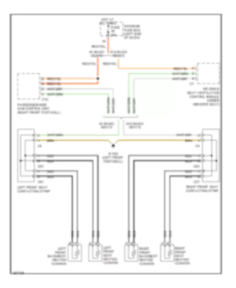
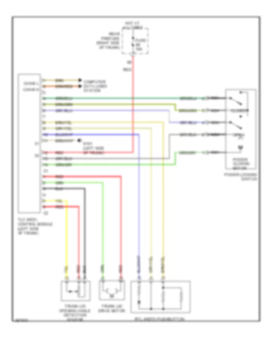
Automatic Door Locks Wiring Diagram (1 of 2) for Mercedes-Benz CLS500 2006
List of elements for Automatic Door Locks Wiring Diagram (1 of 2) for Mercedes-Benz CLS500 2006:
- Can-b h
- Can-b l
- Closed
- Computer data lines system
- Door contact on & off switch
- Door motor
- Fuse 30a
- Hot at all times
- Interior fuse box (left end of dash)
- Left front door central locking motor
- Left front door control module
- Left front door entrance & exit lamp
- Left front door warning lamp
- Left front inside door handle illumination
- Left rear door central locking motor
- Left rear door control module
- Left rear door entrance & exit lamp
- Nca
- Open
- Overhead control panel control module
- Power closing drive motor
- Power locking switch
- Rear prefuse (right side of trunk)
- Red
- Tlc (hds) control module (left side of trunk)
- W15/1 (right front footwell)
- W6/1 (left side of trunk)
Automatic Door Locks Wiring Diagram (2 of 2) for Mercedes-Benz CLS500 2006
List of elements for Automatic Door Locks Wiring Diagram (2 of 2) for Mercedes-Benz CLS500 2006:
- Can-b h
- Can-b l
- Computer data lines system
- Door motor
- Fuse 30a
- Hot at all times
- Interior fuse box (left end of dash)
- Left rear door warning lamp
- Left rear inside door handle illumination
- Nca
- Red
- Right front door central locking motor
- Right front door control module
- Right front door entrance & exit lamp
- Right front door warning lamp
- Right front inside door handle illumination
- Right rear door central locking motor
- Right rear door control module
- Right rear door entrance & exit lamp
- Right rear door warning lamp
- Right rear inside door handle illumination
- W15/1 (right front footwell)
Keyless Go System Wiring Diagram for Mercedes-Benz CLS500 2006
List of elements for Keyless Go System Wiring Diagram for Mercedes-Benz CLS500 2006:
- (left front footwell) w15/2
- Bus data
- Eis (ezs) control unit
- Fuse 25a
- Hot at all times
- Interior fuse box (left end of dash)
- Interior module keyless go control module
- Keyless go trunk antenna
- Keyless go trunk lid button
- Left door handle switch
- Left front opening assist motor
- Left rear door handle switch
- Left rear door keyless go control unit
- Left rear opening assist motor
- Nca
- Rear bumper antenna
- Rear module keyless go control module (left side of trunk)
- Right antenna amplifier module
- Right door handle switch
- Right front opening assist motor
- Right rear door handle switch
- Right rear door keyless go control unit
- Right rear opening assist motor
- W15/1 (right front footwell)
- W15/2 (left front footwell)
- W6 (left side of trunk)
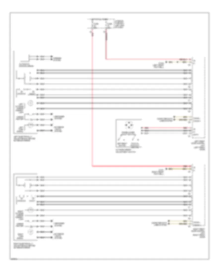
POWER MIRRORS
Automatic Day/Night Mirror Wiring Diagram for Mercedes-Benz CLS500 2006
List of elements for Automatic Day/Night Mirror Wiring Diagram for Mercedes-Benz CLS500 2006:
- 15r
- 58d
- Ambient lamp
- Automatic dimming mirror
- Back auto dimming interior rearview sensor
- C22
- Can-b h
- Can-b l
- Computer data lines system
- Data
- Door
- Forward auto dimming interior rearview sensor
- Fuse 25a
- Garage
- Garage door opener transmitter unit
- Hands-free system microphone group
- Hot at all times
- Interior rearview mirror unit
- Left reading lamp
- Nca
- Opener 1
- Opener 2
- Opener 3
- Overhead control panel control module
- Rain/light sensor
- Rear sam control module w/ fuse & relay module (left side of trunk)
- Right reading lamp
- W6 (left side of trunk)
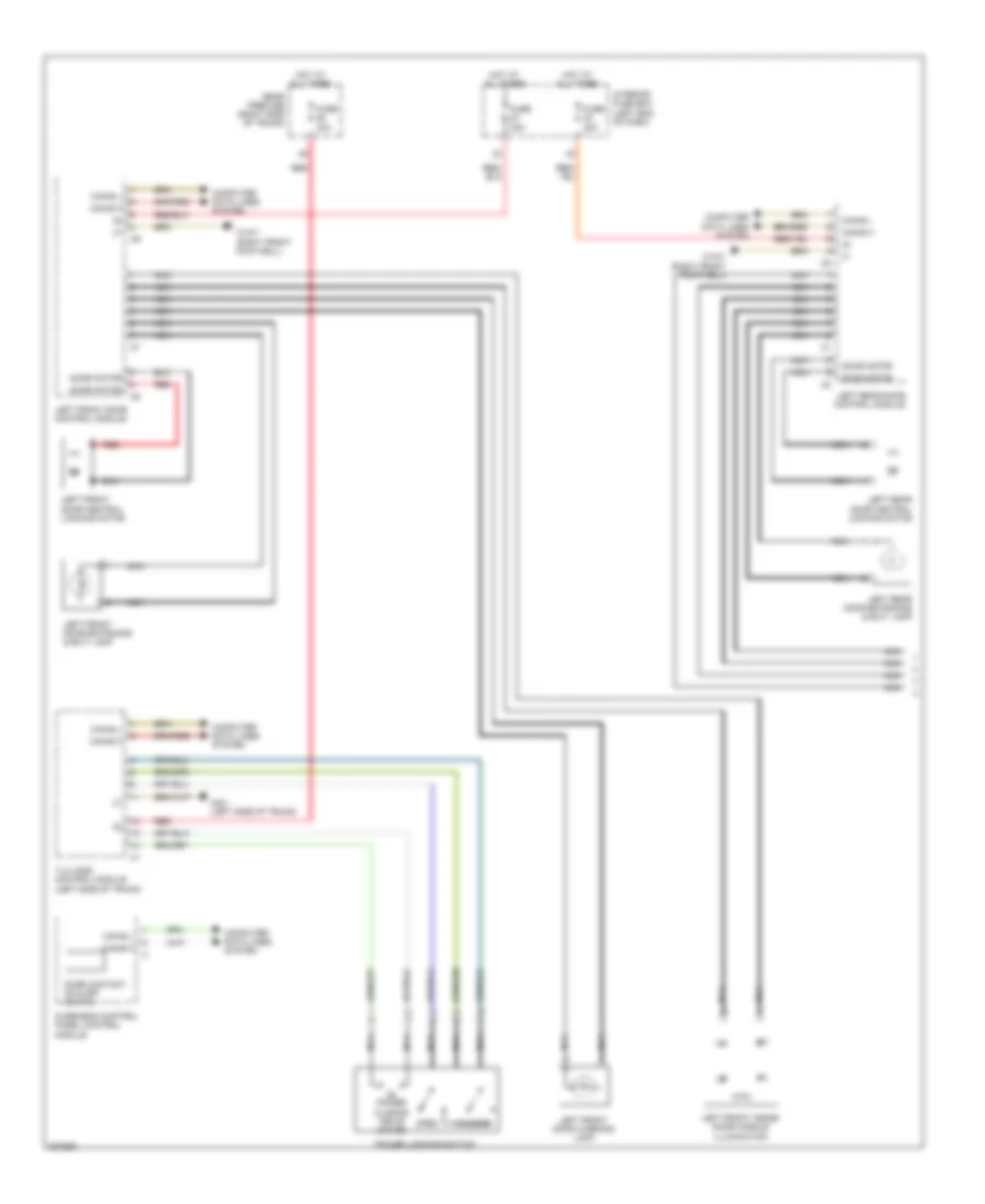
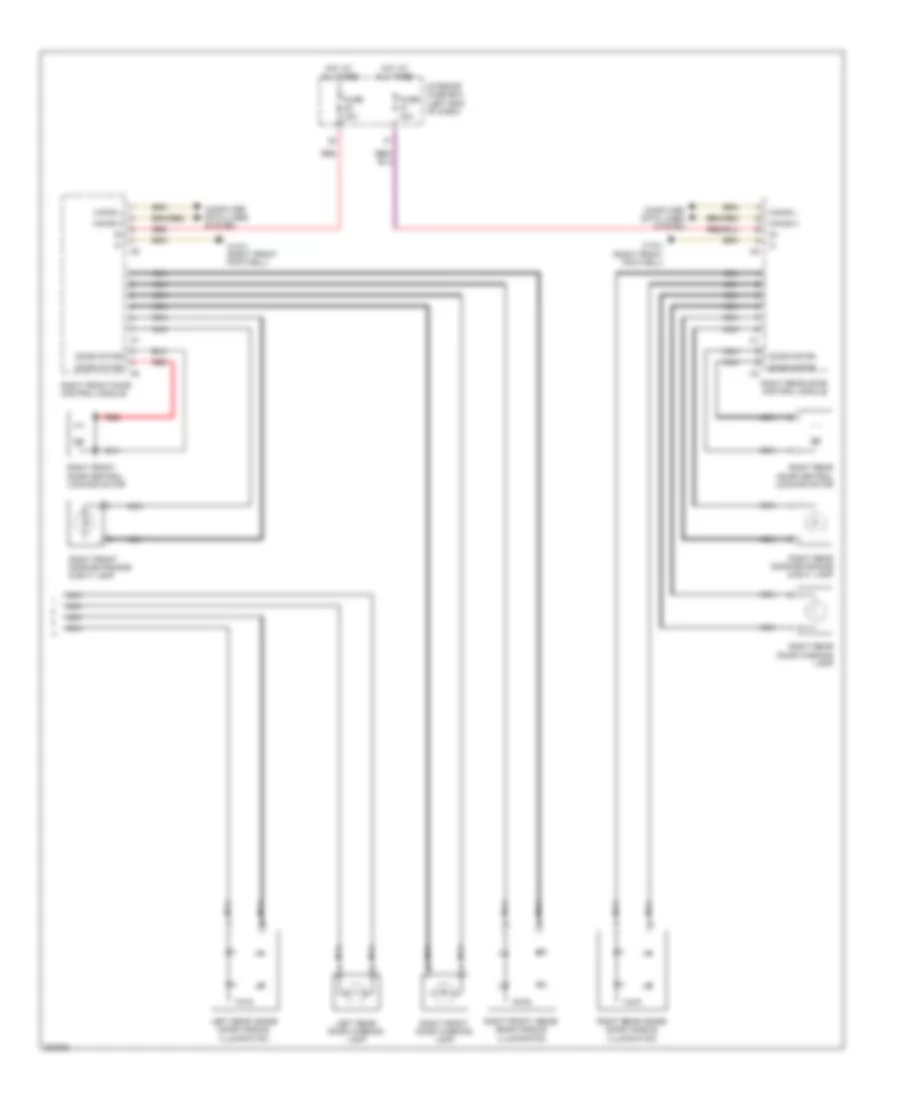
Power Mirror Wiring Diagram for Mercedes-Benz CLS500 2006
List of elements for Power Mirror Wiring Diagram for Mercedes-Benz CLS500 2006:
- Automatic dimming mirror
- Can-b h
- Can-b l
- Computer data lines system
- Data
- Defogger system
- Exterior lights system
- Fold-in, fold-out switch
- Fuse 30a
- Hot at all times
- In/out motor
- Interior fuse box (left end of dash)
- Interior lights system
- Left electrically adjustable & heated exterior mirror
- Left exterior mirror turn signal lamp
- Left front door control unit (left front door)
- Left outside mirror ambient lamp
- Left/right selection switch
- Mirror heater
- Outside mirror adjustment switch
- Raise/lower, in/out rocker switch
- Red
- Right electrically adjustable & heated exterior mirror
- Right exterior mirror turn signal lamp
- Right front door control unit (right front door)
- Right outside mirror ambient lamp
- Up/down motor
- W15/1 (right front footwell)
- W15/2 (left front footwell)
POWER SEATS
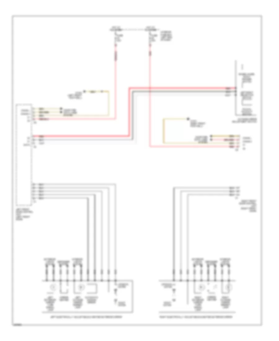
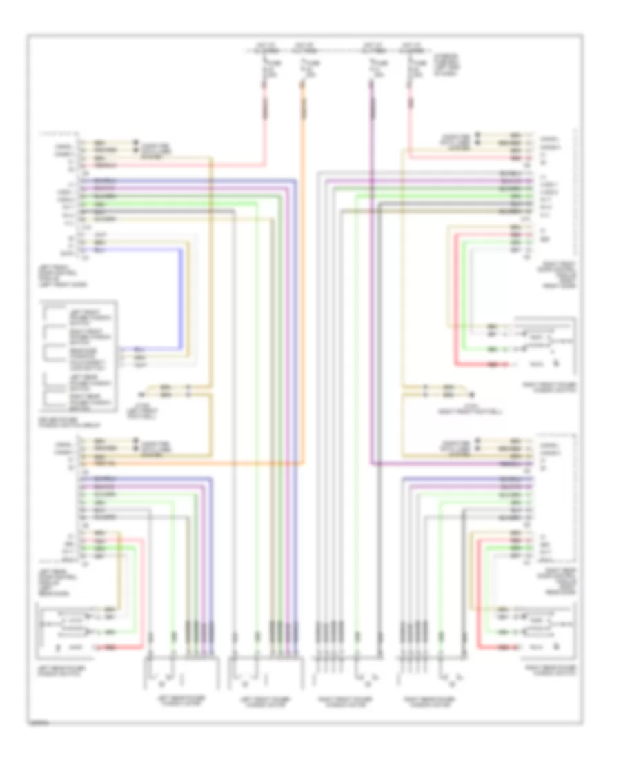
Heated Seats Wiring Diagram for Mercedes-Benz CLS500 2006
List of elements for Heated Seats Wiring Diagram for Mercedes-Benz CLS500 2006:
- C15
- C51
- C61
- Fuse 25a
- Hot at all times
- Hs (sih) & seat ventilation control module (under driver's seat)
- Interior fuse box (left end of dash)
- Left front backrest heated cushion
- Left front seat contacting strip
- Left front seat heated cushion
- Nca
- Passenger-side sam control unit (right front footwell)
- Right front backrest heated cushion
- Right front seat contacting strip
- Right front seat heated cushion
- W/ basic seats
- W/o basic seats
- W15/2 (left front footwell)
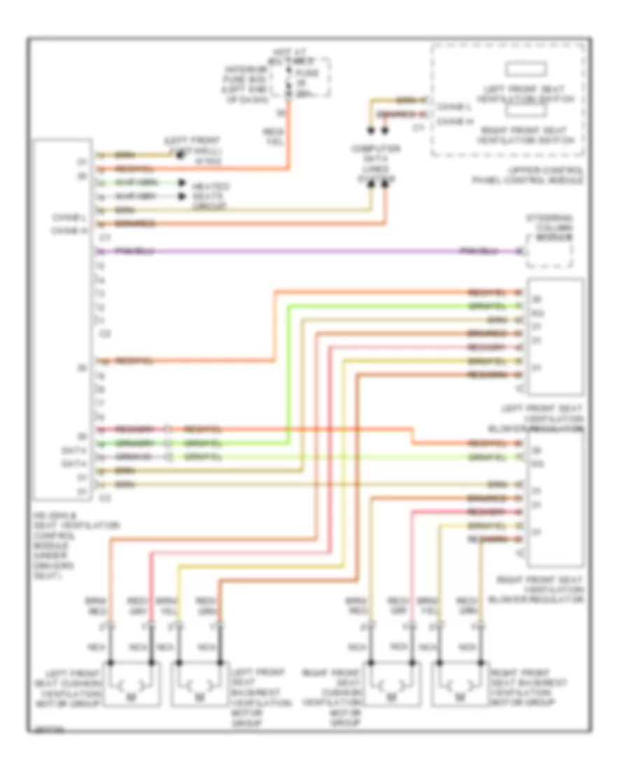
Seat Ventilation Wiring Diagram for Mercedes-Benz CLS500 2006
List of elements for Seat Ventilation Wiring Diagram for Mercedes-Benz CLS500 2006:
- (left front footwell) w15/2
- Can-b h
- Can-b l
- Computer data lines system
- Data
- Fuse 25a
- Heated seats circuit
- Hot at all times
- Hs (sih) & seat ventilation control module (under driver's seat)
- Interior fuse box (left end of dash)
- Left front seat backrest ventilation motor group
- Left front seat cushion ventilation motor group
- Left front seat ventilation blower regulator
- Left front seat ventilation switch
- Nca
- Right front seat backrest ventilation motor group
- Right front seat cushion ventilation motor group
- Right front seat ventilation blower regulator
- Right front seat ventilation switch
- Steering column module
- Upper control panel control module
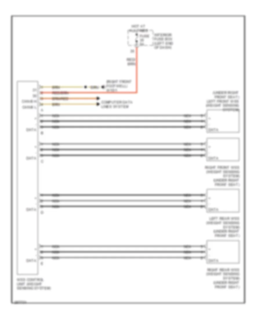
Weight Sensing System Wiring Diagram for Mercedes-Benz CLS500 2006
List of elements for Weight Sensing System Wiring Diagram for Mercedes-Benz CLS500 2006:
- (right front footwell) w15/1
- (under right front seat) left front wss (weight sensing system)
- Can-b h
- Can-b l
- Computer data lines system
- Data
- Fuse 5a
- Hot at all times
- Interior fuse box (left end of dash)
- Left rear wss (weight sensing system) (under right front seat)
- Nca
- Right front wss (weight sensing system) (under right front seat)
- Right rear wss (weight sensing system) (under right front seat)
- Wss control unit (weight sensing system)
POWER TOP/SUNROOF
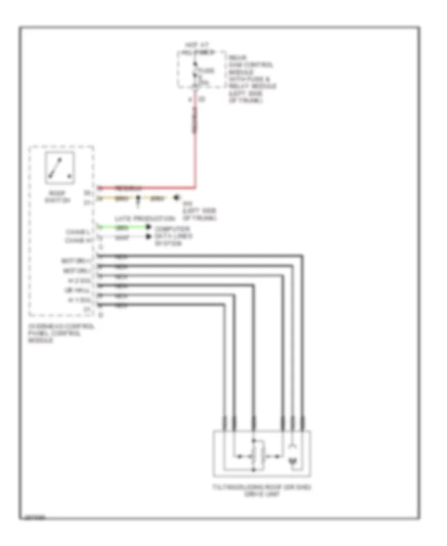
Power Top/Sunroof Wiring Diagram for Mercedes-Benz CLS500 2006
List of elements for Power Top/Sunroof Wiring Diagram for Mercedes-Benz CLS500 2006:
- Can-b h
- Can-b l
- Computer data lines system
- Fuse 25a
- H 1 sig
- H 2 sig
- Hot at all times
- Late production
- Motor(+)
- Motor(-)
- Nca
- Overhead control panel control module
- Rear sam control module with fuse & relay module (left side of trunk)
- Roof switch
- Tilting/sliding roof (sr shd) drive unit
- Ub hall
- W6 (left side of trunk)
POWER WINDOWS
Power Windows Wiring Diagram for Mercedes-Benz CLS500 2006
List of elements for Power Windows Wiring Diagram for Mercedes-Benz CLS500 2006:
- (+)
- 58d
- C10
- Can-b h
- Can-b l
- Computer data lines system
- Data
- Driver power window switch group
- Fh h
- Fh t
- Fuse 30a
- H (-)
- H sig 1
- H sig 2
- Hot at all times
- Interior fuse box (left end of dash)
- Left front door control module (left front door)
- Left front power window motor
- Left front power window switch
- Left rear door control module (left rear door)
- Left rear power window motor
- Left rear power window switch
- Rear side windows child safety lock switch
- Red
- Right front door control module (right front door)
- Right front power window motor
- Right front power window switch
- Right rear door control module (right rear door)
- Right rear power window motor
- Right rear power window switch
- W15/1 (right front footwell)
- W15/2 (left front footwell)
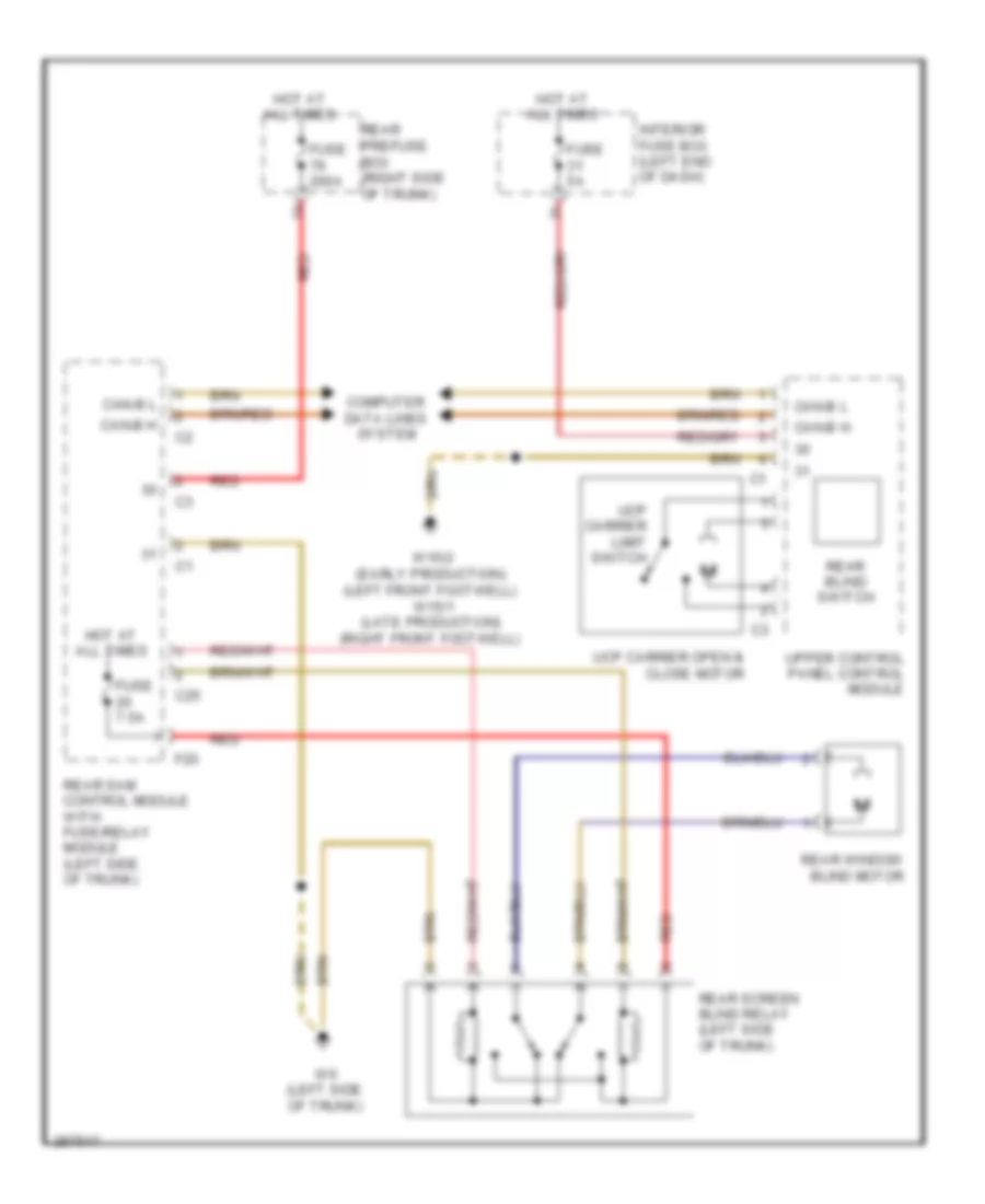
Rear Window Sun Shade Wiring Diagram for Mercedes-Benz CLS500 2006
List of elements for Rear Window Sun Shade Wiring Diagram for Mercedes-Benz CLS500 2006:
- C25
- Can-b h
- Can-b l
- Computer data lines system
- F20
- Fuse 200a
- Fuse 5a
- Fuse 7.5a
- Hot at all times
- Interior fuse box (left end of dash)
- Rear blind switch
- Rear prefuse box (right side of trunk)
- Rear sam control module with fuse/relay module (left side of trunk)
- Rear screen blind relay (left side of trunk)
- Rear window blind motor
- Red
- Ucp carrier limit switch
- Ucp carrier open & close motor
- Upper control panel control module
- W15/2 (early production) (left front footwell) w15/1 (late production) (right front footwell)
- W6 (left side of trunk)
RADIO
COMAND Actuation Wiring Diagram for Mercedes-Benz CLS500 2006
List of elements for COMAND Actuation Wiring Diagram for Mercedes-Benz CLS500 2006:
- Accept/ terminate phone call pushbutton
- Audio gateway control module (left side of trunk)
- Can-b h
- Can-b l
- Can-c h
- Can-c l
- Comand operating, display & control module
- Computer data lines system
- Data
- Fanfare horns and airbag clock spring contact
- Fuse 15a
- Hot at all times
- Interior fuse box (left end of dash)
- Left multifunction steering wheel pushbutton group (w/ steering wheel gear shifter)
- Left multifunction steering wheel pushbutton group (w/ steering wheel heater)
- Most
- Most data bus circuit
- Most in
- Most out
- Nca
- Nf-l
- Nf-r
- Out
- Pnk
- Pushbutton + & -, setting of specific function & volume control
- Red
- Right multifunction steering wheel pushbutton group (w/ steering wheel gear shifter)
- Right multifunction steering wheel pushbutton group (w/ steering wheel heater)
- Scroll forward/ back pushbutton
- Scroll forward/back pushbutton
- Separation point
- Shield
- Steering column module
- Steering wheel gear shift signal processing module (inside steering wheel)
- Steering wheel heater electronics (if equipped)
- System selection pushbutton
- W/ steering wheel gear shifter
- W/o steering wheel gear shifter
- W15/2 (left front footwell)
- Wake-up
- Walkman
MOST Data Bus Wiring Diagram for Mercedes-Benz CLS500 2006
List of elements for MOST Data Bus Wiring Diagram for Mercedes-Benz CLS500 2006:
- (if equipped)
- Audio gateway control module (left side of trunk)
- Cd changer
- Comand operating, display & control module
- Most
- Navigation processor (left side of trunk)
- Out
- Pnk
- Sdar control unit (right side of trunk)
- Universal portable ctel interface (upci (uhi)) control module (center front of trunk)
- Voice control system (vcs (sbs)) control unit (right front of trunk)
- Wake-up
- Wake-up signal connector
Radio Wiring Diagram for Mercedes-Benz CLS500 2006
List of elements for Radio Wiring Diagram for Mercedes-Benz CLS500 2006:
- (if equipped) cd changer
- (left side of trunk) w6
- Antenna
- Audio gateway control module (left side of trunk)
- Aut
- Bass module loudspeaker (if equipped)
- C11
- C23
- C28
- Can-b h
- Can-b l
- Center cockpit speaker (centerfill)
- Computer data lines system
- Emergency call system control unit (center front of trunk)
- Fuse 40a
- Fuse 7.5a
- Hot at all times
- Interior fuse box (left end of dash)
- Left antenna amplifier module (left "c" pillar)
- Left front door speaker group
- Left rear door speaker group
- Left rear surround loudspeaker (if equipped)
- Most
- Most data bus circuit
- Most in
- Most out
- Most wake-up
- Nca
- Pnk
- Rear sam control module w/ fuse & relay module (left side of trunk)
- Red
- Right front door speaker group
- Right rear door speaker group
- Right rear surround loudspeaker (if equipped)
- Shield
- Sound amplifier microphone
- Tweeter
- W15/1 (right front footwell)
- Wake-up
- Woofer
- Zf-out
Satellite Radio Wiring Diagram for Mercedes-Benz CLS500 2006
List of elements for Satellite Radio Wiring Diagram for Mercedes-Benz CLS500 2006:
- (right side of trunk)
- Fuse 5a
- Hot at all times
- Most
- Most data bus circuit
- Most in
- Most out
- Nca
- Pnk
- Rear prefuse box (right side of trunk)
- Sat
- Sdar antenna
- Sdar control unit
- Ter
- W17/1 (left "c" pillar)
- Wake-up
Voice Activation Wiring Diagram for Mercedes-Benz CLS500 2006
List of elements for Voice Activation Wiring Diagram for Mercedes-Benz CLS500 2006:
- (or red)
- D2b in
- D2b out
- Early production
- Emergency call system control unit (center front of trunk)
- Fuse 5a
- Gnd
- Hands-free system microphone group
- Hot at all times
- Late production
- Mic +
- Mic -
- Mic 1
- Mic 2
- Mic 3
- Mic 4
- Most
- Most data bus circuit
- Nca
- Pnk
- Rear prefuse (right side of trunk)
- Shield
- Voice control system (vcs (sbs)) control unit (right front of trunk)
- W17/1 (left "c" pillar)
SHIFT INTERLOCK
Shift Interlock Wiring Diagram for Mercedes-Benz CLS500 2006
List of elements for Shift Interlock Wiring Diagram for Mercedes-Benz CLS500 2006:
- (left front footwell) (w/ 7 speed a/t) w15/2
- 7-speed a/t
- C15
- C17
- Can-c h
- Can-c l
- Chassis circuit 87 relay
- Computer data lines system
- Driver side sam control module w/ fuse & relay module (left side of engine compt)
- Electronic selector lever module control module
- Engine circuit 87 relay
- Etc (egs) control module (w/ etc) (right front footwell) electric control unit (7-speed a/t)
- Fuse 150a
- Fuse 7.5a
- Gear display sensor
- Hot at all times
- Left voltage distributor (can) connector
- Rear prefuse box (right side of trunk)
- Red
- W/ etc
- W15/1 (w/ etc) (right front footwell)
- W28/1
- W36/1 (at right front footwell)
STARTING/CHARGING
Charging Wiring Diagram for Mercedes-Benz CLS500 2006
List of elements for Charging Wiring Diagram for Mercedes-Benz CLS500 2006:
- Abr
- Auxiliary battery
- Auxiliary battery relay
- Battery
- Battery control unit (early production) (at battery)
- Battery sensor (late production)
- Can-b h
- Can-b l
- Computer data lines system
- Cutoff relay for interruptible loads
- Early production
- Front prefuse
- Fuse
- Fuse 150a
- Fuse 5a
- Generator
- Late production
- Lin
- Me-sfi (me) control unit (left rear of engine compt)
- Rear prefuse box (right side of trunk)
- Red
- Starter
- Terminal block
- W10 (right side of trunk)
Starting Wiring Diagram for Mercedes-Benz CLS500 2006
List of elements for Starting Wiring Diagram for Mercedes-Benz CLS500 2006:
- Auxiliary battery
- Auxiliary battery relay
- Battery
- Battery control unit (early production) (at battery)
- Can-c h
- Can-c l
- Charging circuit
- Circuit 87 relay engine
- Circuit relay
- Computer data lines system
- Driver side sam control module w/ fuse & relay module (left side of engine compt)
- Front prefuse
- Fuse 150a
- Fuse 59 15a
- Hot at all times
- Me-sfi (me) control unit (left rear of engine compt)
- Red
- Solid state
- Starter
- Starter relay
- Str
- System power distribution
- W10 (right side of trunk)
SUPPLEMENTAL RESTRAINTS
Emergency Seat Belt Tensioners Wiring Diagram for Mercedes-Benz CLS500 2006
List of elements for Emergency Seat Belt Tensioners Wiring Diagram for Mercedes-Benz CLS500 2006:
- Can h
- Can l
- Computer data lines system
- Driver-side sam control module w/ fuse & relay module
- Front prefuse box
- Fuse 40a
- Hot at all times
- Left front reversible emergency tensioning retractor
- Rear prefuse box
- Right front reversible emergency tensioning retractor
- W15/1
- W15/2
Supplemental Restraint Wiring Diagram (1 of 2) for Mercedes-Benz CLS500 2006
List of elements for Supplemental Restraint Wiring Diagram (1 of 2) for Mercedes-Benz CLS500 2006:
- (pins 5 thru 32: not used)
- 15r
- Ab1 d1+
- Ab1 d1-
- Ab1 p1+
- Ab1 p1-
- Ab2 d2+
- Ab2 d2-
- Ab2 p2+
- Ab2 p2-
- Can h
- Can l
- Computer data lines system
- Crash
- Crash sig
- Driver seat belt buckle restraint systems switch
- Driver side frontal accel- eration sensor
- Driver-side sam control module w/ fuse & relay module
- Drvr belt
- Etr d+
- Etr d-
- Etr lr+
- Etr lr-
- Etr p+
- Etr p-
- Etr rr+
- Etr rr-
- Fuse 5a
- Gkb fa+
- Gkb fa-
- Hot at all times
- Interior fuse box
- Left airbags sensor
- Left front wss sensor
- Left rear wss sensor
- Nca
- Pass belt
- Passenger seat belt buckle restraint systems switch
- Passenger seat occupied and child seat recognition sensor
- Passenger side frontal accel- eration sensor
- Red
- Restraint systems control module
- Right airbags sensor
- Right front wss sensor
- Right rear wss sensor
- Sb d+
- Sb d-
- Sb lr+
- Sb lr-
- Sb p+
- Sb p-
- Sb rr+
- Sb rr-
- Side l
- Side r
- Upfront l
- Upfront r
- W15/1
- W26
- Wb l+
- Wb l-
- Wb r+
- Wb r-
- Weight sensing system (wss) control unit
Supplemental Restraint Wiring Diagram (2 of 2) for Mercedes-Benz CLS500 2006
List of elements for Supplemental Restraint Wiring Diagram (2 of 2) for Mercedes-Benz CLS500 2006:
- Clock spring
- Driver airbag squib 1
- Driver airbag squib 2
- Driver etr squib
- Driver kneebag squib
- Driver side airbag squib
- Front passenger airbag squib 1
- Front passenger airbag squib 2
- Front passenger etr squib
- Left front window airbag squib
- Left rear etr squib
- Left rear side airbag squib
- Red
- Right front window airbag squib
- Right rear etr squib
- Right rear side airbag squib
- Right side airbag squib
- Steering column module
- W15/1
- W15/2
TRANSMISSION
Transmission Wiring Diagram, 5 Speed A/T for Mercedes-Benz CLS500 2006
List of elements for Transmission Wiring Diagram, 5 Speed A/T for Mercedes-Benz CLS500 2006:
- (+)
- (-)
- 1-2/ 4-5 valve sol vlv
- 2-3 shift sol vlv
- 3-4 shift sol vlv
- Can-c h
- Can-c l
- Computer data lines system
- Ctrl sol vlv
- Data link connector (dlc) (under left side of dash)
- Diag
- Driver side sam control module with fuse & relay module (left side of engine compt)
- Eis (ezs) control unit
- Electric control unit
- Electric steering lock control module (on steering column)
- Electronic selector lever module control module
- Etc (egs) control module (right front footwell)
- Fuse 7.5a
- Gear display sensor
- Gnd
- Hot w/ circuit 87 relay chassis energized
- Keyless go start/stop pushbutton (if equipped)
- Modu- lating press ctrl sol vlv
- Nca
- P r n d- d+
- Passenger-side sam control module (right front footwell)
- Reversing & parking lock locking solenoid
- Rpm sensor
- Shift press
- Sig
- Starter lockout contact
- Torque converter lockup pwm sol vlv
- Trans temp sensor
- W/ keyless go
- W15/1 (right front footwell)
Transmission Wiring Diagram, 7 Speed A/T for Mercedes-Benz CLS500 2006
List of elements for Transmission Wiring Diagram, 7 Speed A/T for Mercedes-Benz CLS500 2006:
- B1 brake ctrl sol vlv
- B2 brake ctrl sol vlv
- B3 brake ctrl sol vlv
- Can-c h
- Can-c l
- Computer data lines system
- Driver side sam control module with fuse & relay module (left side of engine compt) i7
- Eis (ezs) control unit
- Electric control unit (vgs)
- Electric steering lock control module (on steering column)
- Electronic selector lever module control module
- Fuse 7.5a
- Gear display sensor
- Gnd
- Hot w/ circuit 87 relay chassis energized
- Internal speed sensor (vgs)
- K1 clutch ctrl sol vlv
- K2 clutch ctrl sol vlv
- K3 clutch ctrl sol vlv
- Keyless go start/stop pushbutton (if equipped)
- Nca
- Output speed sensor (vgs)
- P r n d- d+
- Passenger-side sam control module (right front footwell)
- Reversing & parking lock locking solenoid
- Selection range sensor
- Torque converter lockup ctrl sol vlv
- Transmission oil temp sensor
- Turbine speed sensor (vgs)
- W/ keyless go
- W15/1 (right front footwell)
- W15/2 (left front footwell)
- Working press ctrl sol vlv
TRUNK, TAILGATE, FUEL DOOR
Trunk Pull-Down Wiring Diagram for Mercedes-Benz CLS500 2006
List of elements for Trunk Pull-Down Wiring Diagram for Mercedes-Benz CLS500 2006:
- Can-b h
- Can-b l
- Closed
- Computer data lines system
- Fuse 30a
- Hot at all times
- Nca
- Open
- Power closing motor
- Power locking switch
- Rear prefuse (right side of trunk)
- Red
- Rtl (hdfs) pushbutton
- Tlc (hds) control module (left side of trunk)
- Trunk lid drive motor
- Trunk lid opening angle detection sensor
- W6/1 (left side of trunk)
WARNING SYSTEMS
Seat Belt Warning Wiring Diagram for Mercedes-Benz CLS500 2006
List of elements for Seat Belt Warning Wiring Diagram for Mercedes-Benz CLS500 2006:
- (right front footwell) (late production) w15/1
- 31e
- Air bag ind & warning lamp
- Audible turn signal ind
- Brake fluid & parking brake warning lamp
- Brake fluid indicator switch
- Can b h
- Can b l
- Can c h
- Can c l
- Computer data lines system
- Driver seat belt buckle restraint systems switch
- Driver side sam control module w/ fuse & relay module (left side of engine compt)
- Drvr belt
- Dtr warning lamp
- Early production
- Esp & abs warning lamp
- Esp control unit (left rear of engine compt)
- Fuse 7.5a
- Hot at all times
- Hot in run or start
- I13
- Instrument cluster
- Multifunction display
- Nca
- Parking brake indicator switch
- Production) (left front footwell)
- Restraint systems control module (under front of center console)
- Right front brake pad contact sensor
- Right rear brake pad contact sensor
- Seat belt reminder lamp
- W15/1 (right front footwell)
- W15/2 (early
- W2 (right front of engine compartment)
- W26 (under center console)
- Warning buzzer
Tire Pressure Monitoring Wiring Diagram for Mercedes-Benz CLS500 2006
List of elements for Tire Pressure Monitoring Wiring Diagram for Mercedes-Benz CLS500 2006:
- Can-b h
- Can-b l
- Center tpm antenna
- Fuse 7.5a
- Hot at all times
- Left front tpm wheel antenna
- Left front tpm wheel sensor
- Left rear tpm wheel sensor
- Rear sam control module with fuse/relay module (left side of trunk)
- Red
- Right front tpm wheel antenna
- Right front tpm wheel sensor
- Right rear tpm wheel sensor
- Tps control module
WIPER/WASHER
Headlamp Washer Wiring Diagram for Mercedes-Benz CLS500 2006
List of elements for Headlamp Washer Wiring Diagram for Mercedes-Benz CLS500 2006:
- (right side of trunk)
- Can-b h
- Can-b l
- Computer data lines system
- Driver-side sam control module w/ fuse & relay module (left rear of engine compt)
- Exterior lamp switch
- Fuse 200a
- Hcs (sra) switch
- Hcs pump
- Hot at all times
- I10
- Rear prefuse
- Red
- Sra
- W15/2 (left front footwell)
Wiper/Washer Wiring Diagram for Mercedes-Benz CLS500 2006
List of elements for Wiper/Washer Wiring Diagram for Mercedes-Benz CLS500 2006:
- (right side of trunk)
- Can-b h
- Can-b l
- Can-c h
- Can-c l
- Combination switch
- Computer data lines system
- Coolant level indicator switch
- Di control module
- Driver-side sam control module w/ fuse & relay module (left rear of engine compt)
- Early production
- Fuse 200a
- Fuse 40a
- Hot at all times
- Hot in on or start
- Late production
- Left washer nozzle heater
- Motor
- Overhead control panel control module
- Rear prefuse
- Rear sam control module w/ fuse & relay module (left side of trunk)
- Red
- Right washer nozzle heater
- Steering column module
- W15/2 (left front footwell)
- W2 (right front of engine compt)
- Washer nozzle hose heater
- Windshield washer fluid level indicator switch
- Windshield washer fluid pump
- Windshield washer system switch
- Wiper motor
- Wiper switch

 Čeština
 Dansk
Dansk Deutsch
 Ελληνικά
 English
 English
 Español
 Français
 Français
 עברית
עברית Hrvatski
 Magyar
 Italiano
 日本語
日本語 한국어
한국어 Nederlands
 Polski
 Português
 Português
 Română
 Русский
 Slovenčina
 Slovenščina
 Svenska
 Türkçe
 中文 (中国)