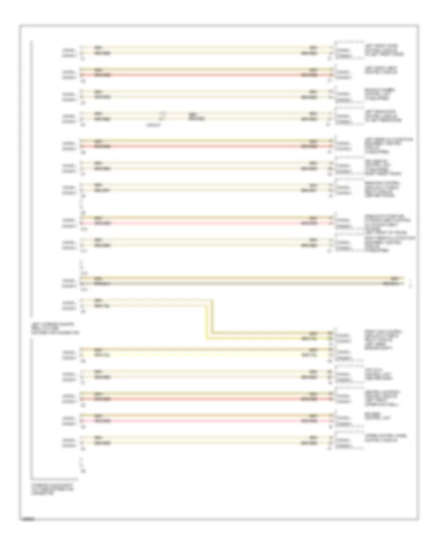
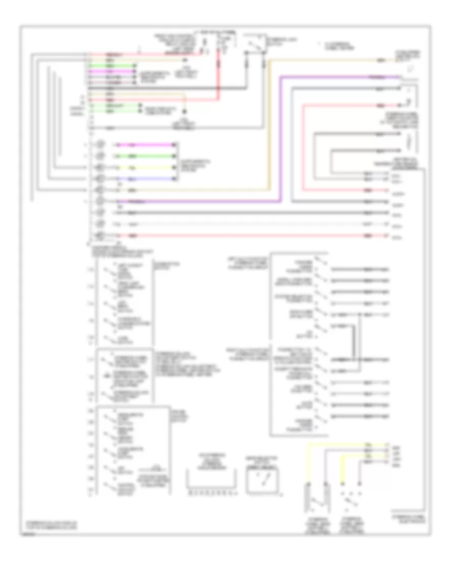
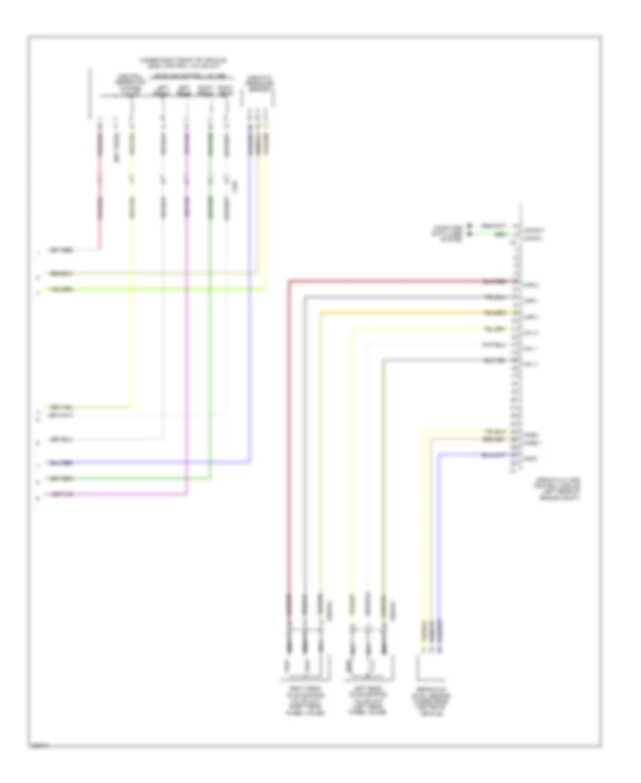
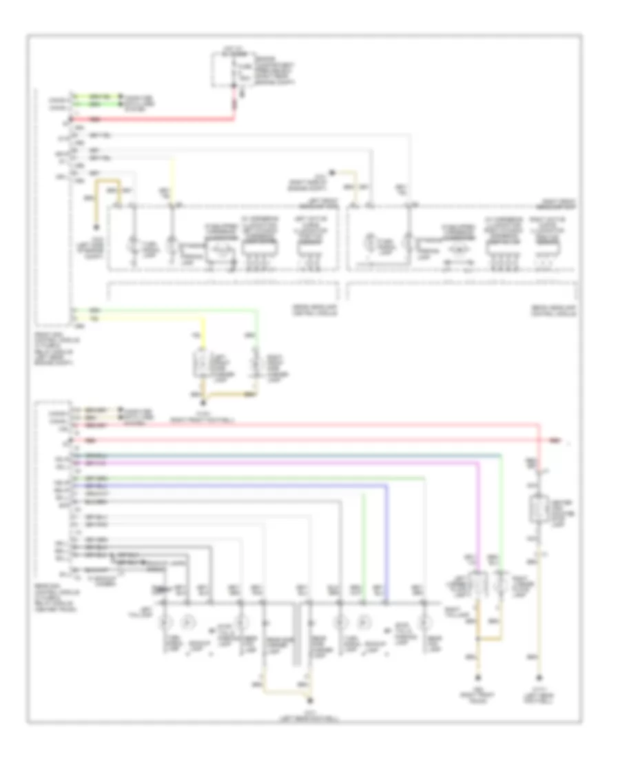
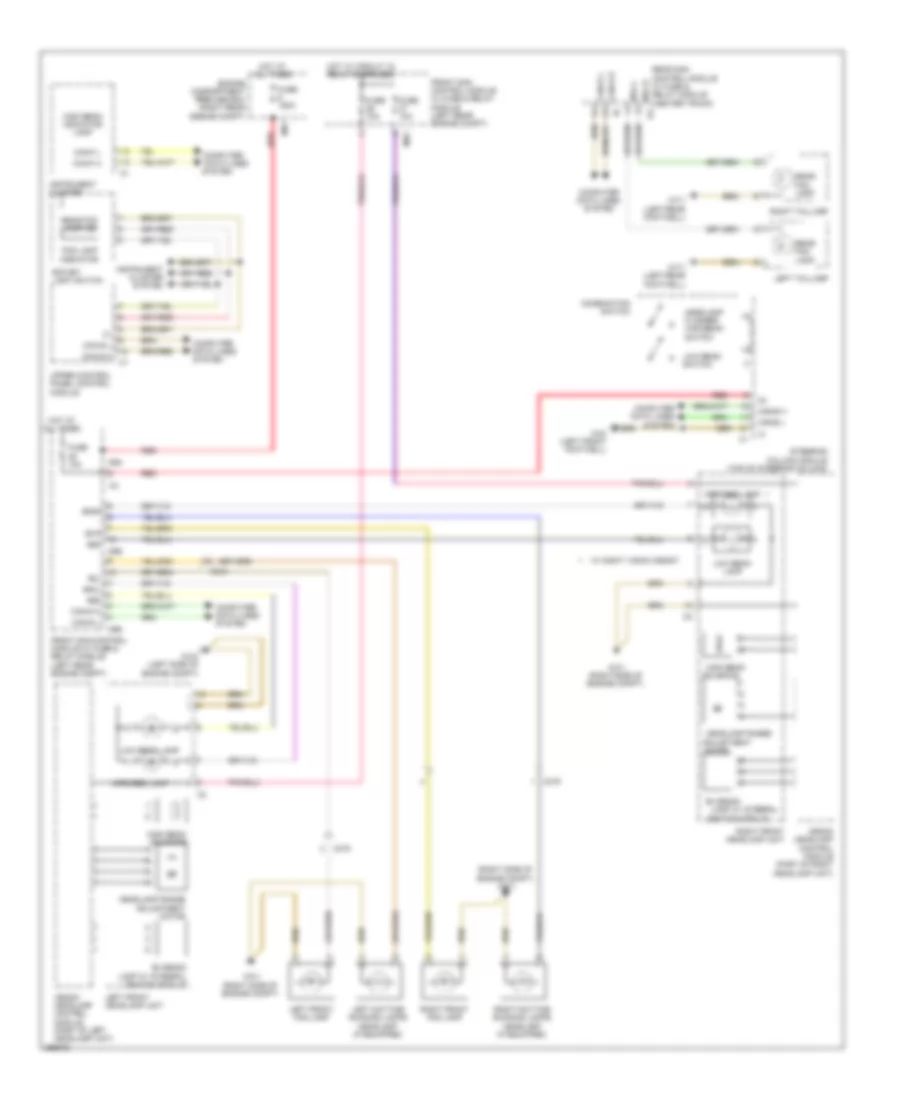
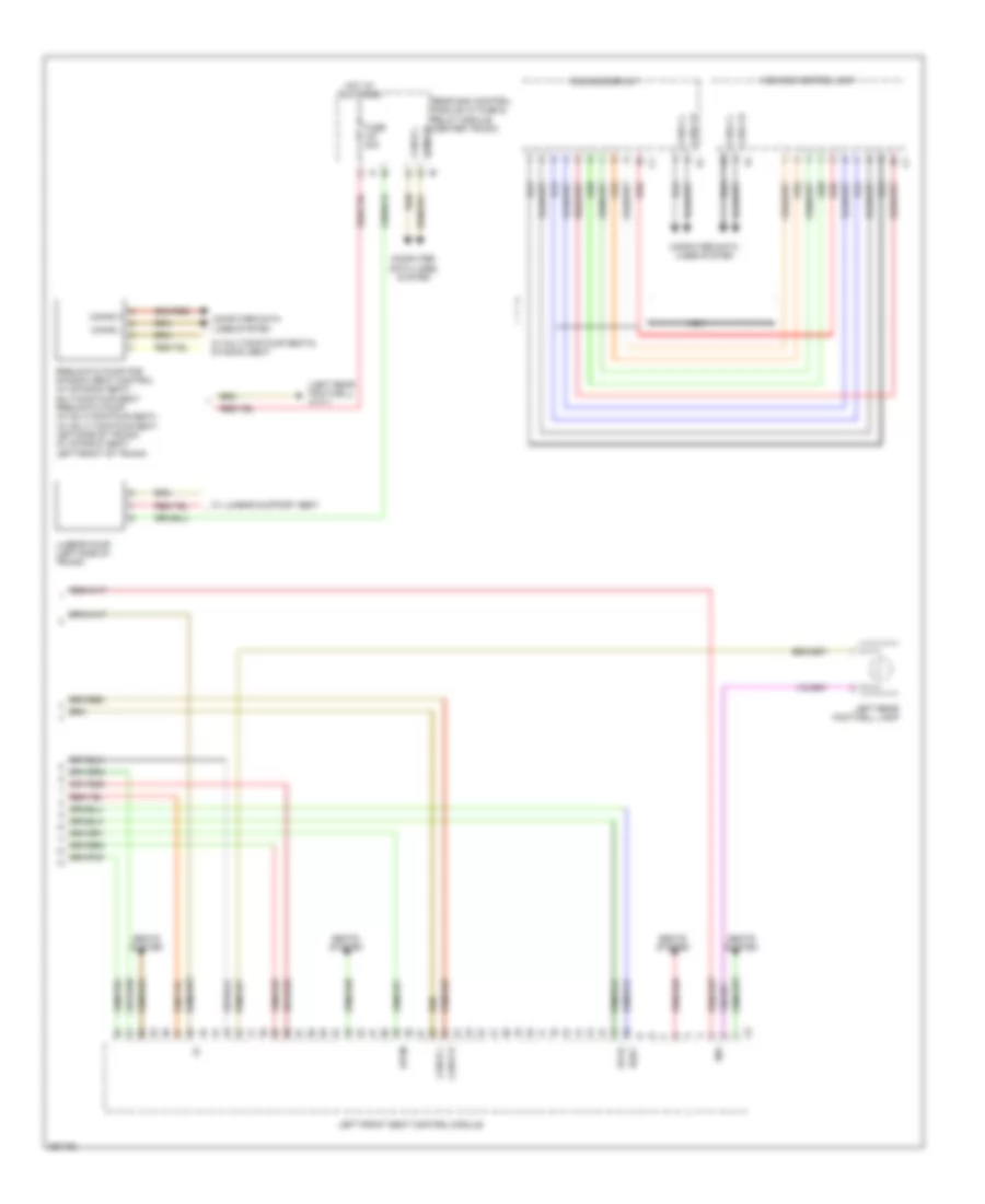
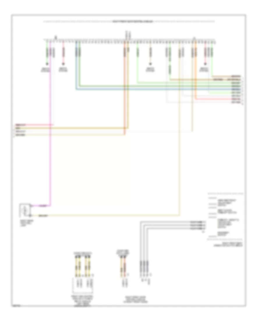
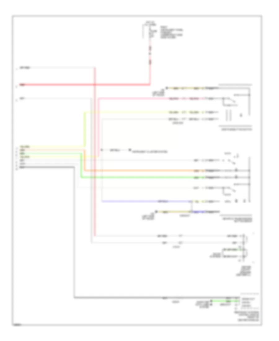
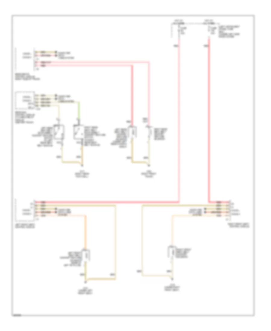
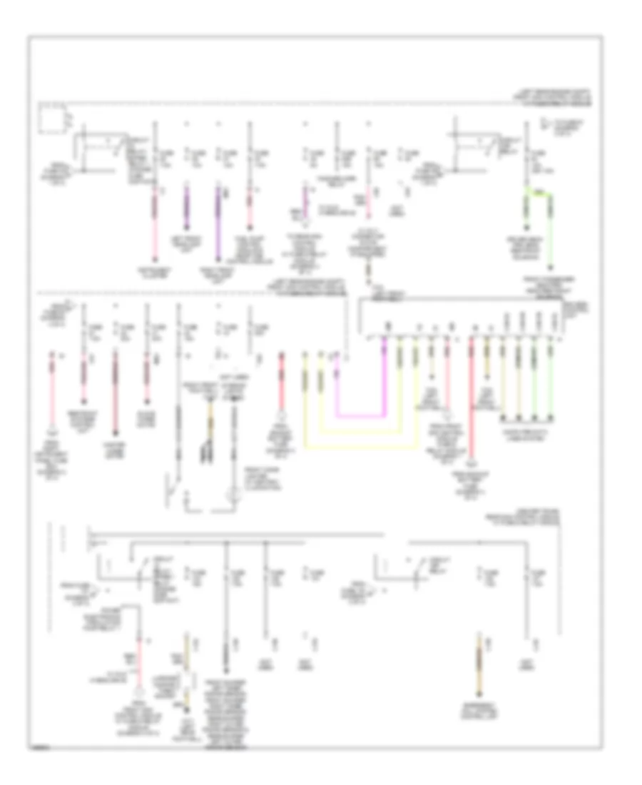
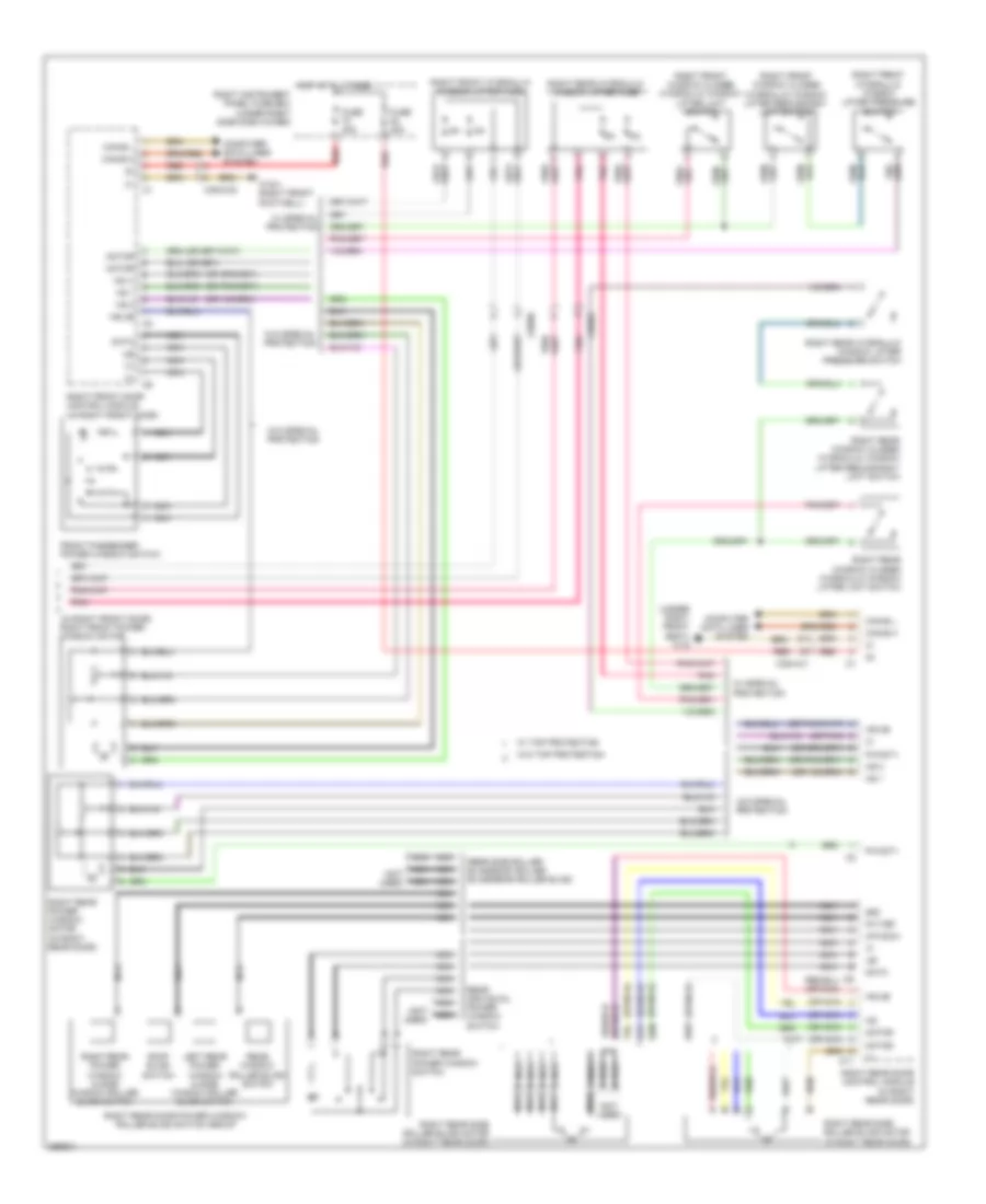
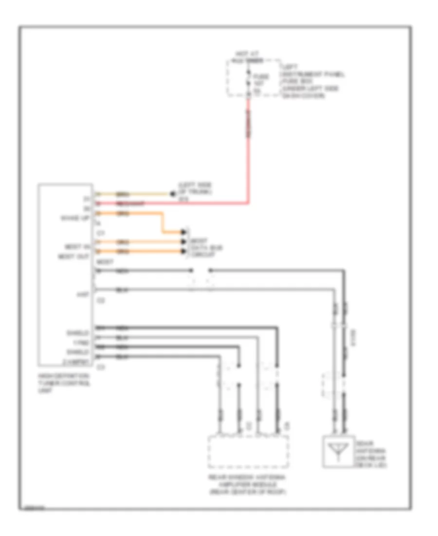
AIR CONDITIONING
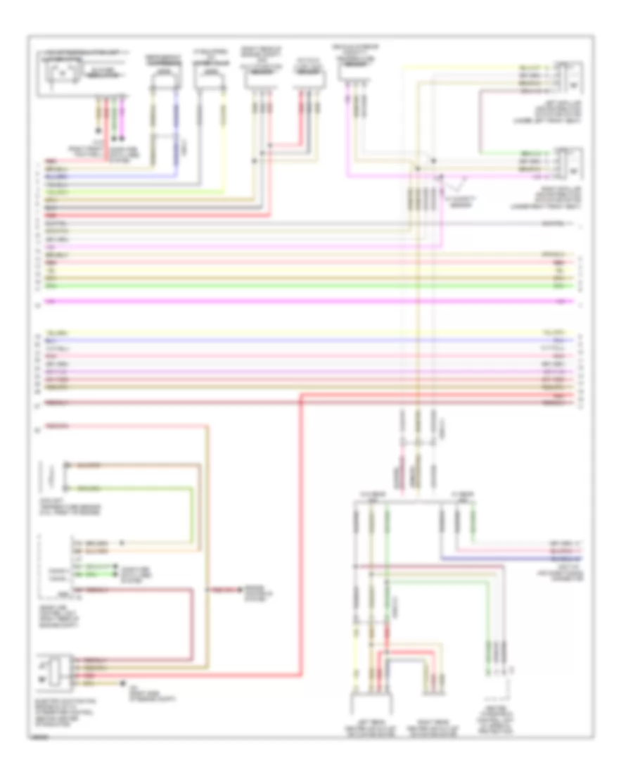
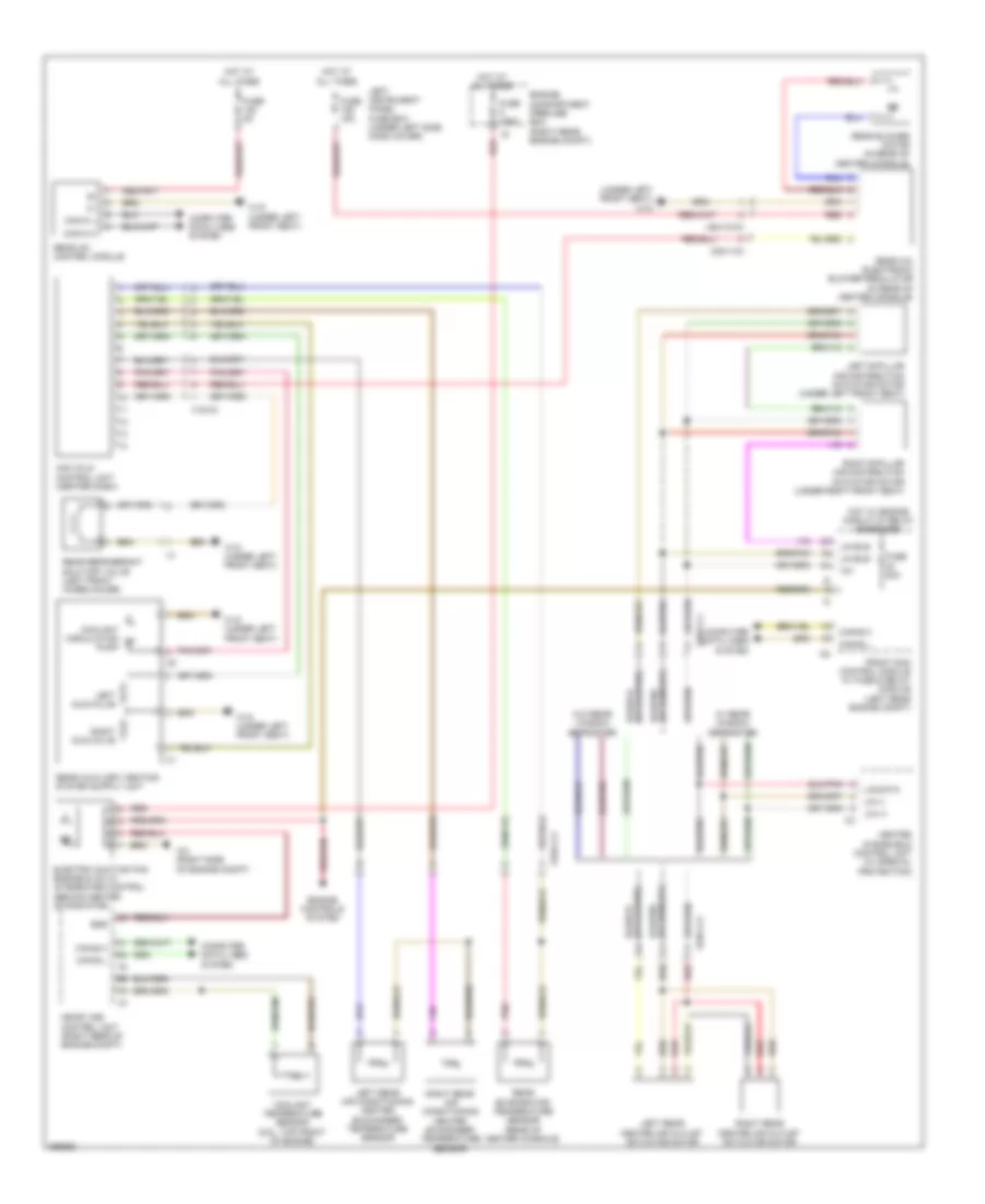
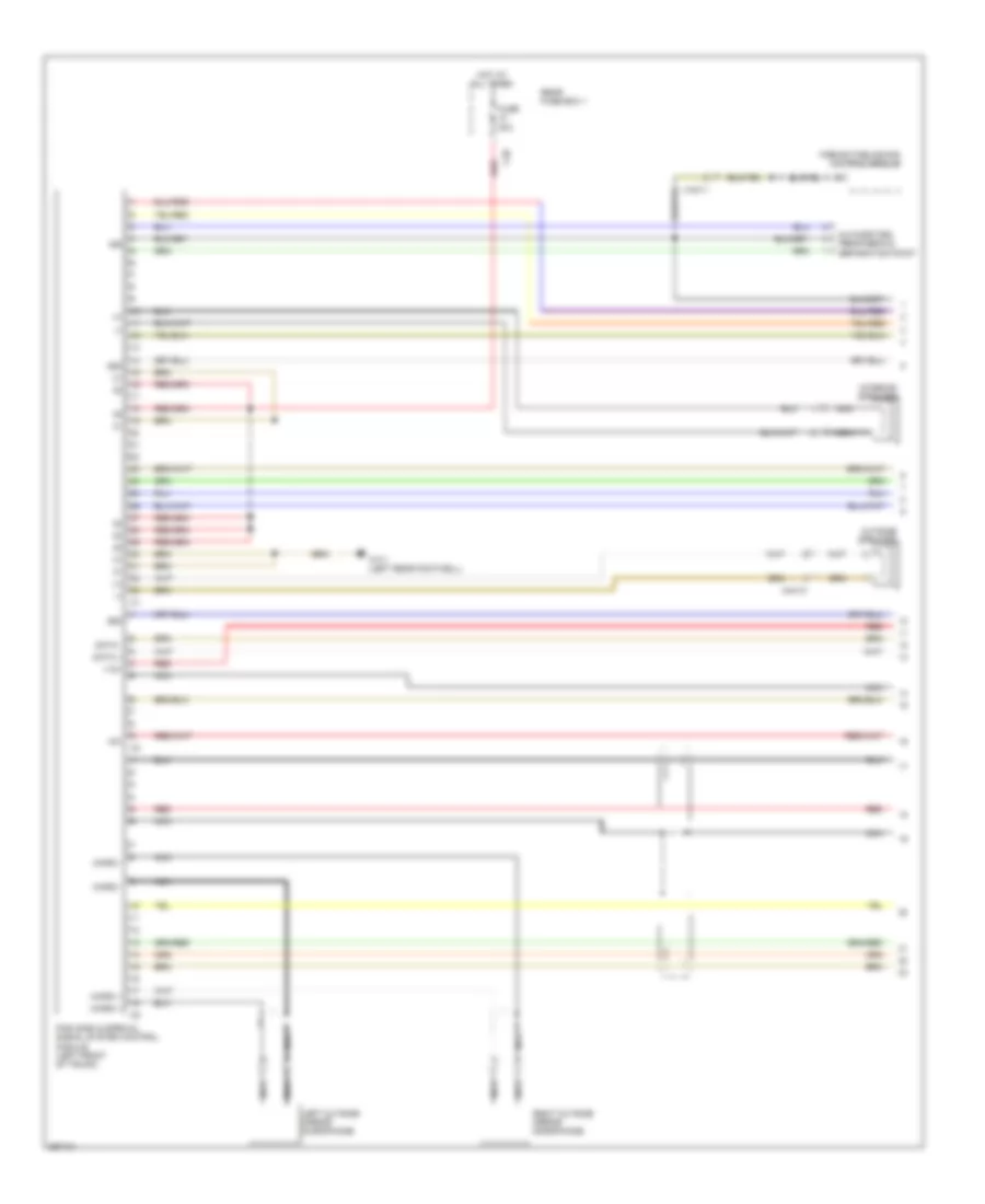
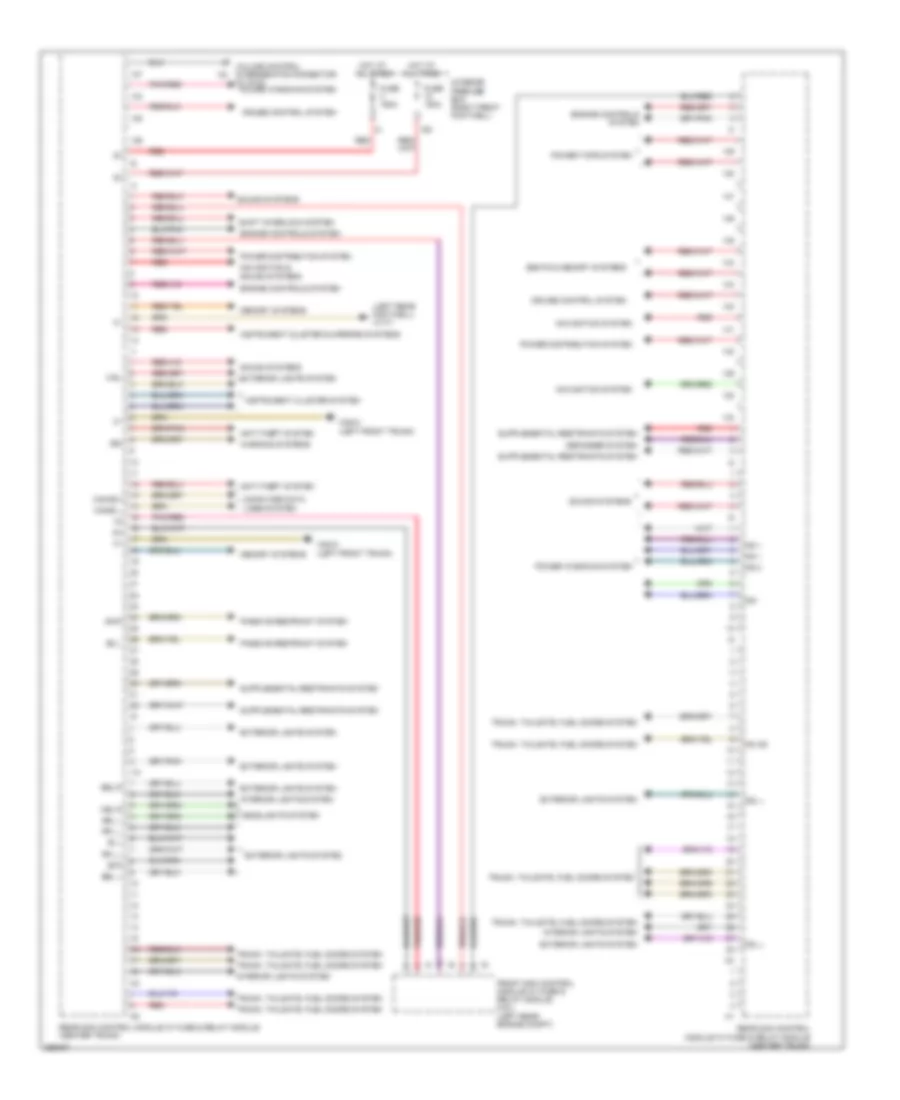
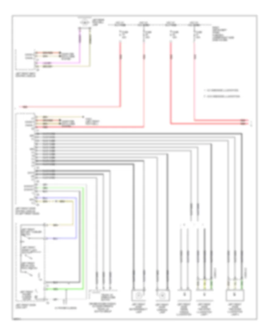
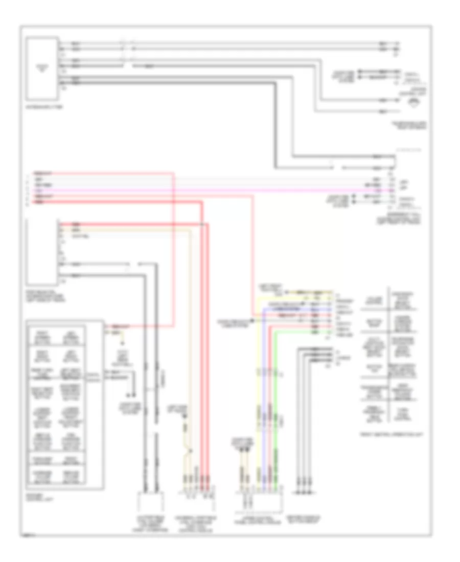
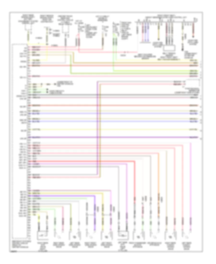
Automatic A/C Wiring Diagram (1 of 3) for Mercedes-Benz S550 2011
 https://portal-diagnostov.com/license.html
Automotive Electricians Portal FZCO
Automotive Electricians Portal FZCO
https://portal-diagnostov.com/license.html
https://portal-diagnostov.com/license.html
Automotive Electricians Portal FZCO
Automotive Electricians Portal FZCO
List of elements for Automatic A/C Wiring Diagram (1 of 3) for Mercedes-Benz S550 2011:
- (left front footwell) w34
- (right rear footwell) w17
- +12v
- +5v
- 12v
- 58d
- Aac (kla) control unit (center dash)
- Can-b h
- Can-b l
- Computer data lines system
- Data
- Front center air outlet potentiometer
- Front sam control module w/ fuse & relay module (left rear engine compt)
- Fuse 15a
- Fuse 20a
- Fuse 40a
- Fuse 5a
- Gnd
- Hot at all times
- Hot w/ chassis circuit 87 relay energized
- Hot w/ engine circuit 87 relay energized
- Klb 12v
- Klb data
- Klb gnd
- Left side air outlet potentiometer
- Lin 12v
- Lin bus
- Lin data
- Lin gnd
- Lin-bus
- Mr7
- Mr8
- Pnk
- Rear center air outlet potentiometer
- Red
- Refrigerant pressure sensor (left front wheelhouse)
- Right side air outlet potentiometer
- Sig
- W34 (left front footwell)
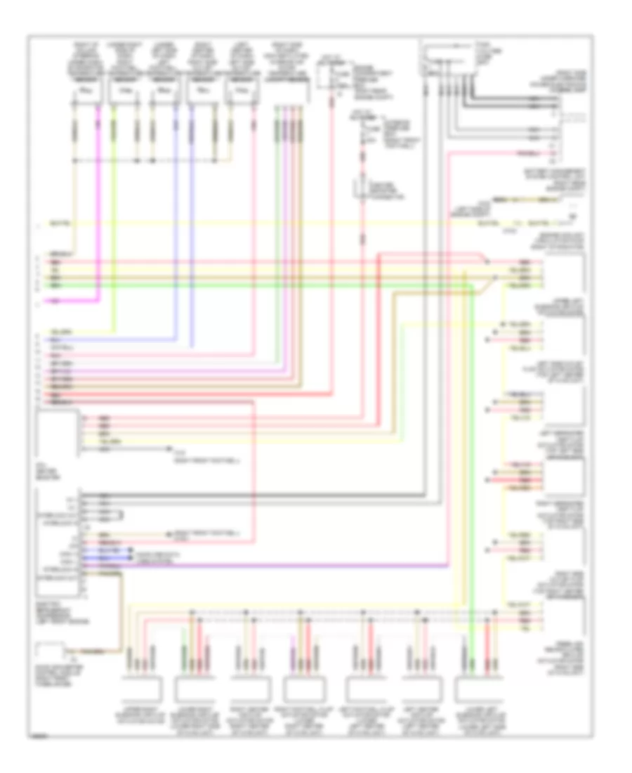
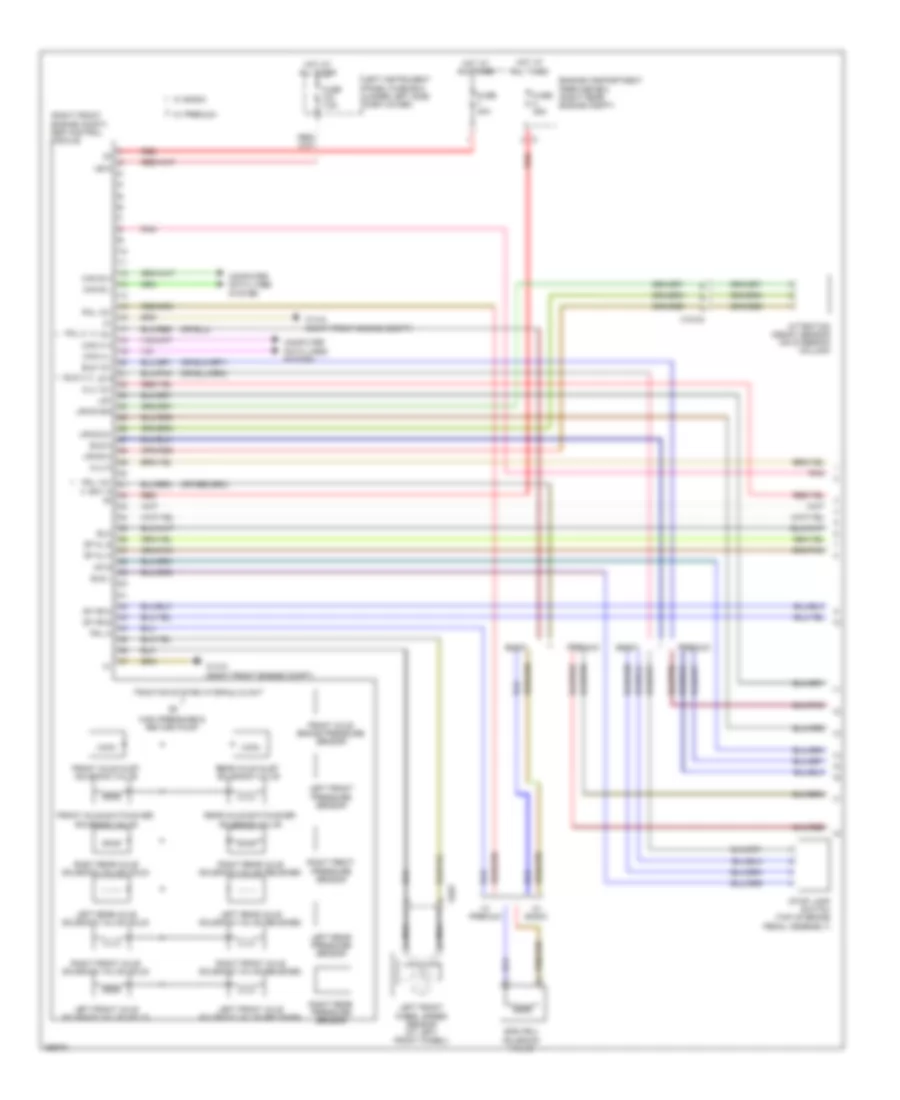
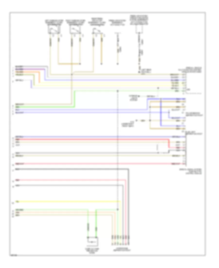
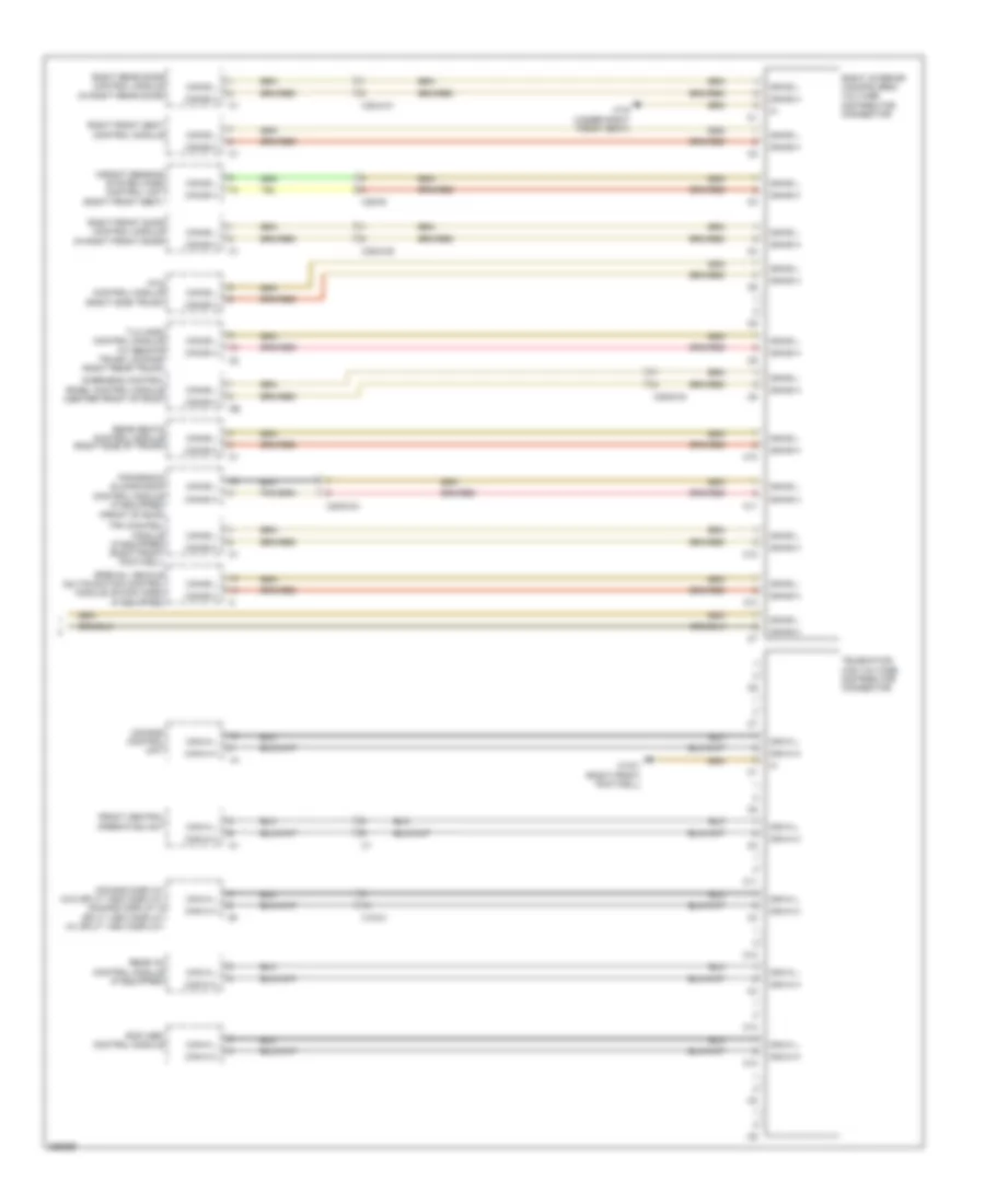
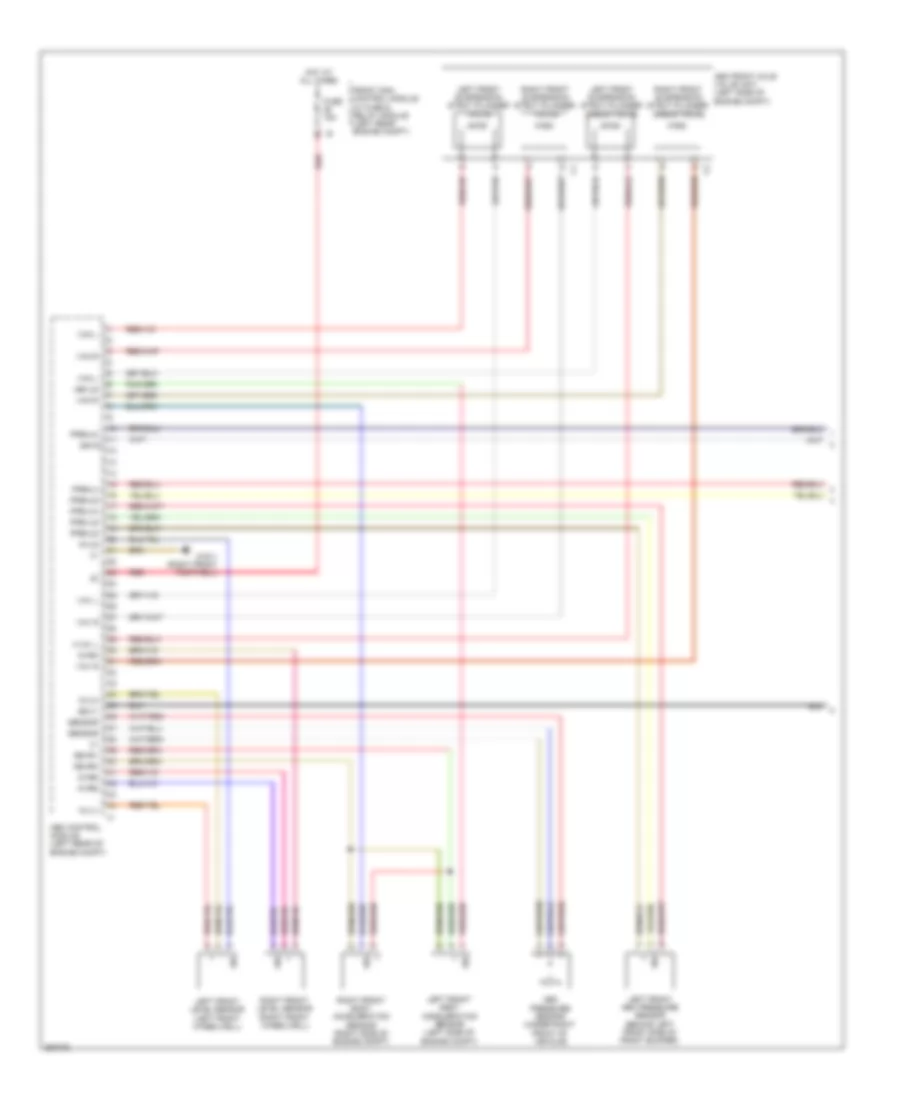
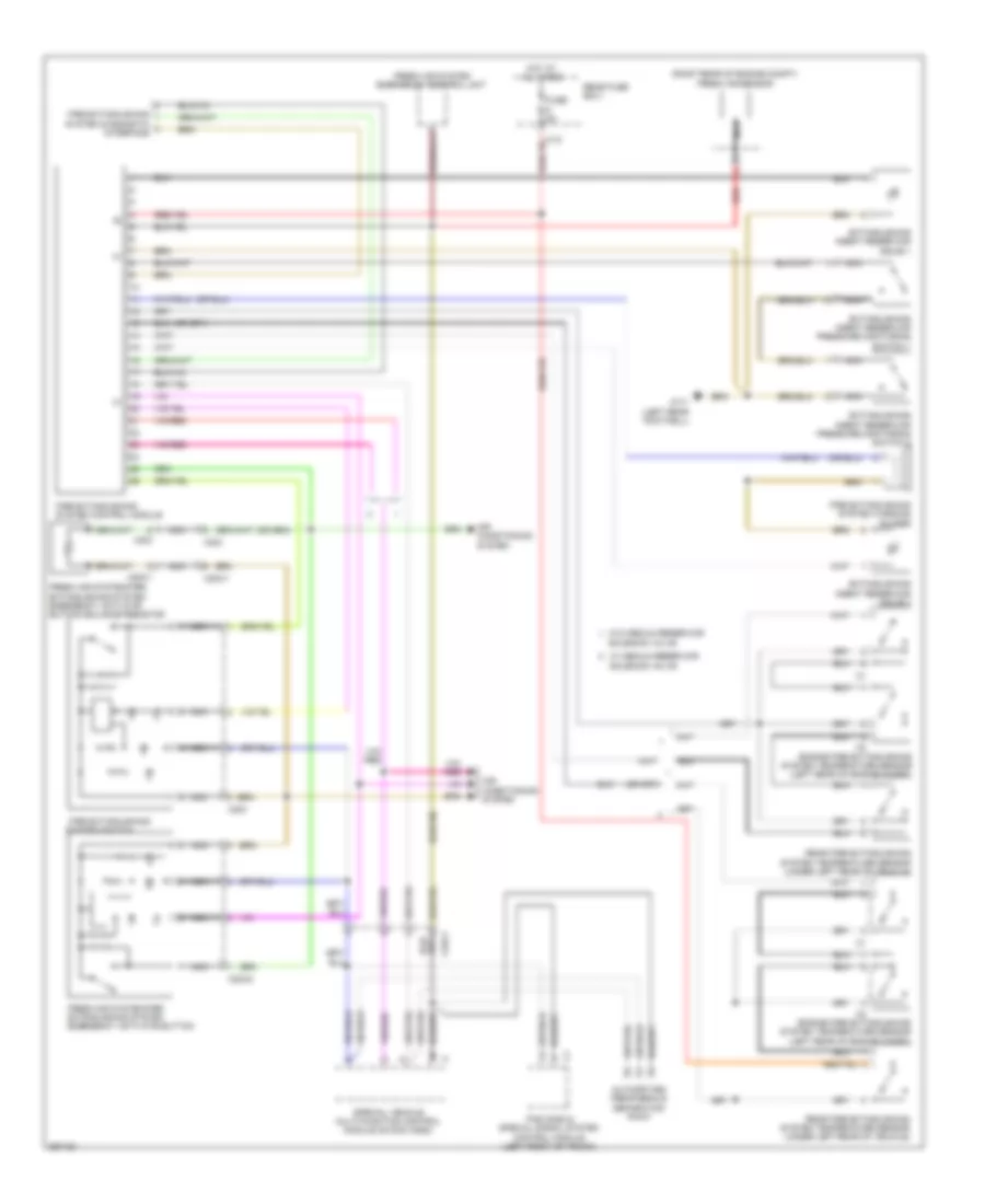
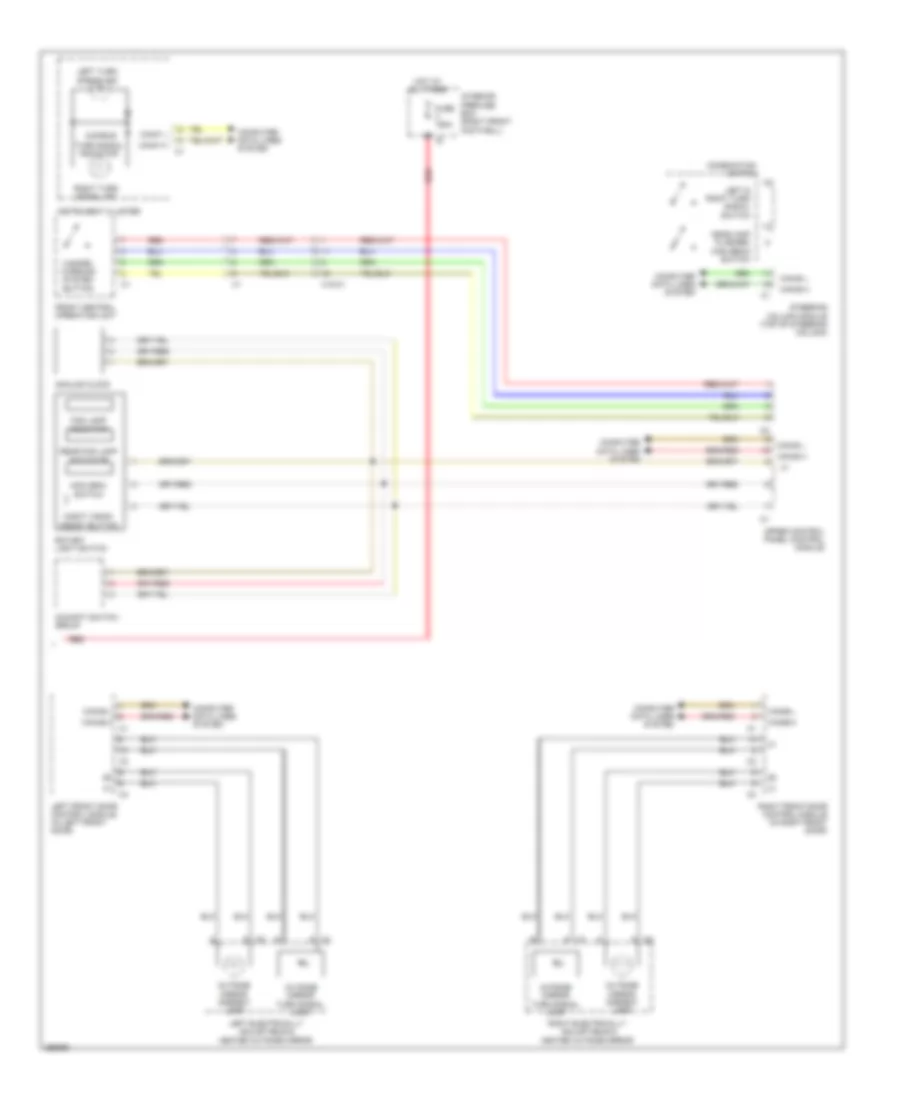
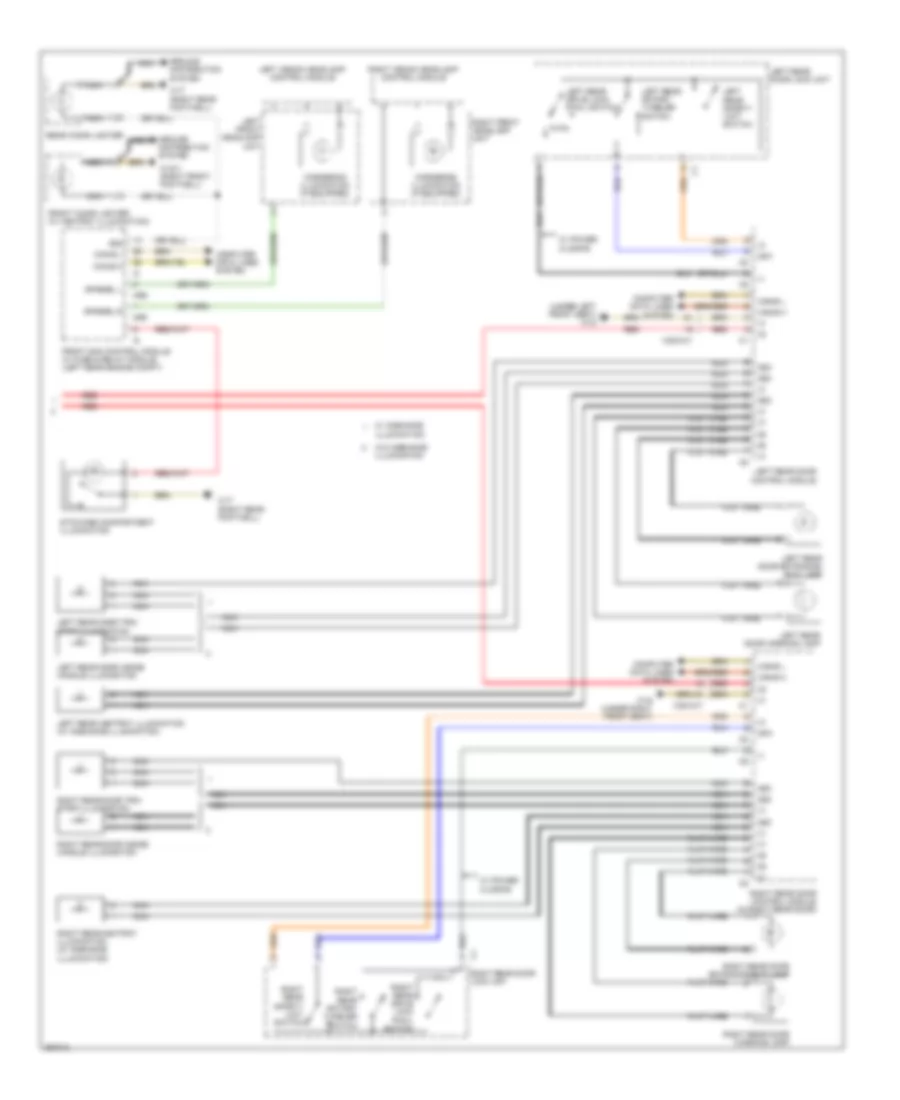
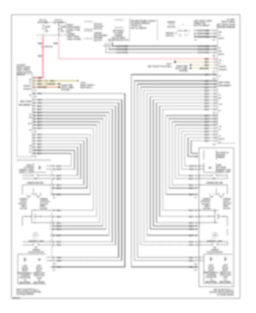
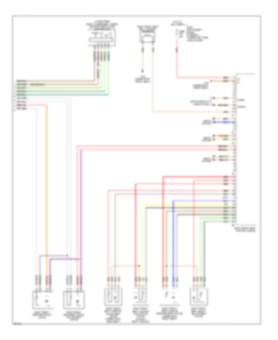
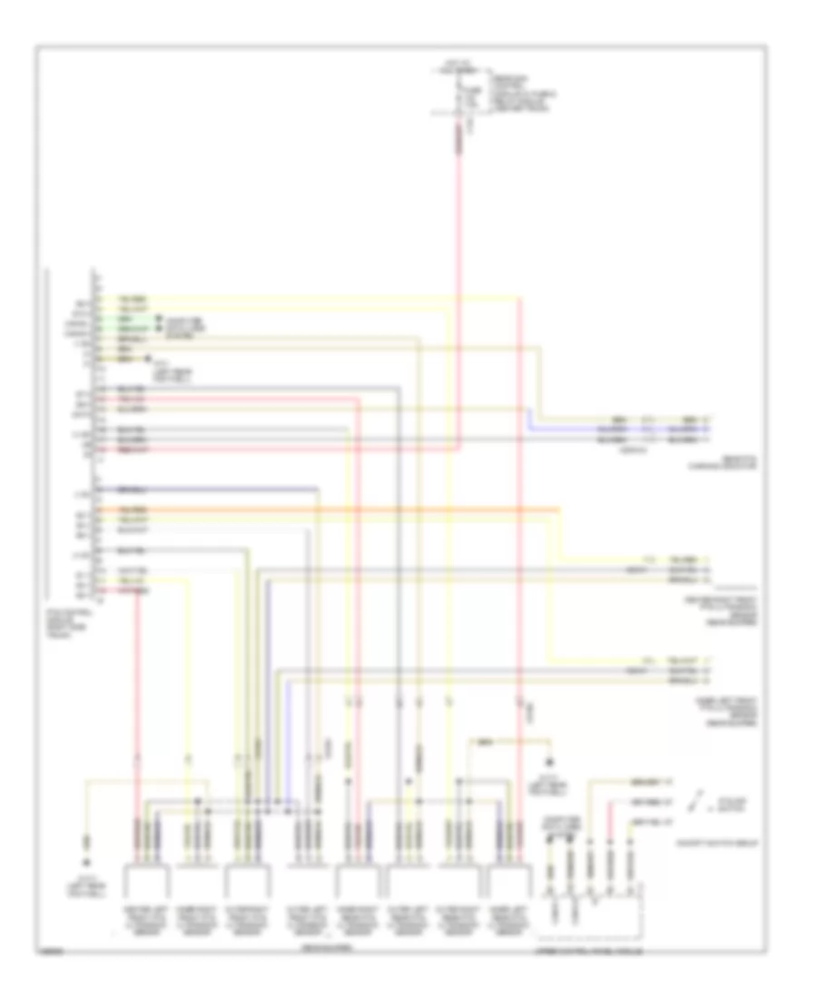
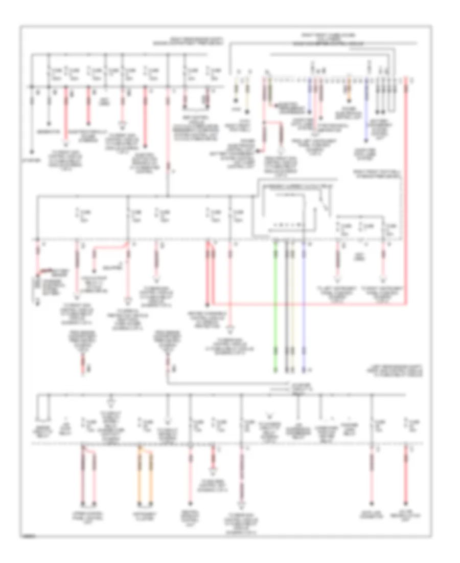
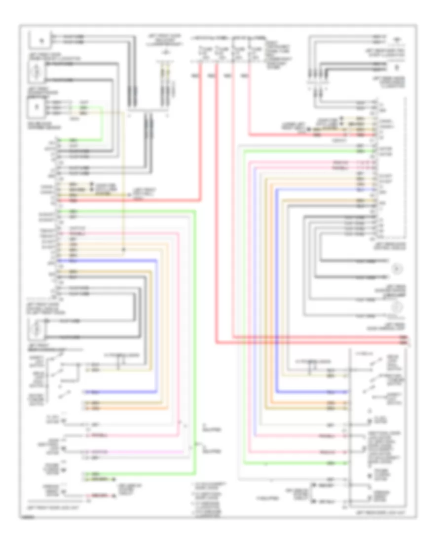
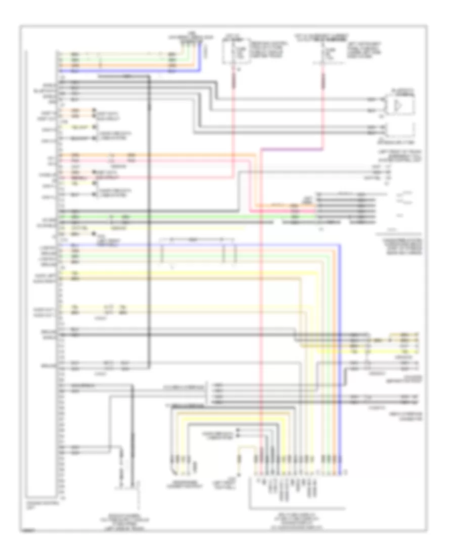
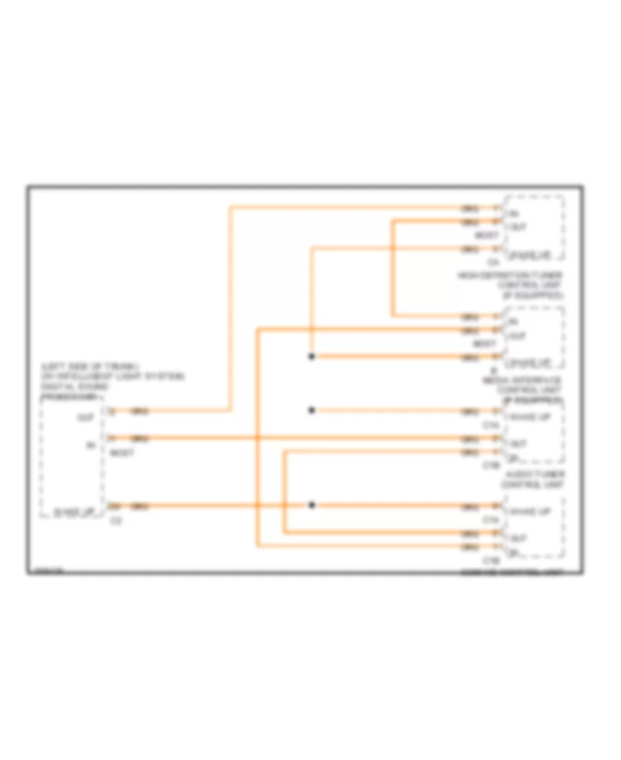
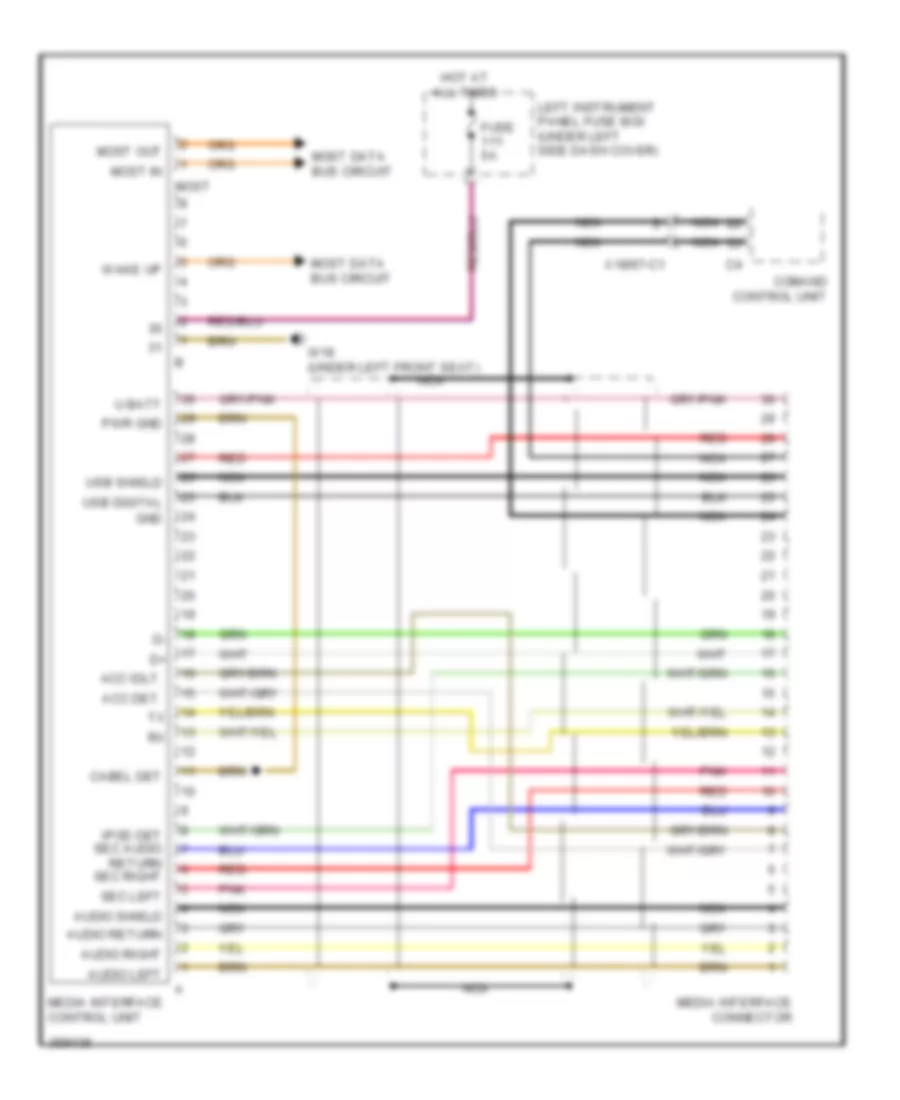
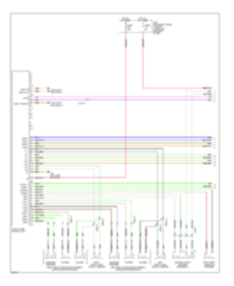
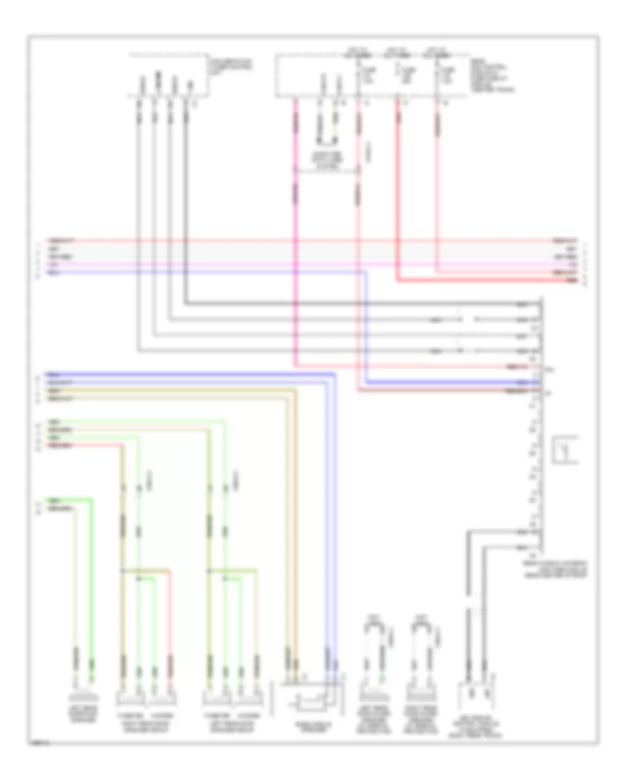
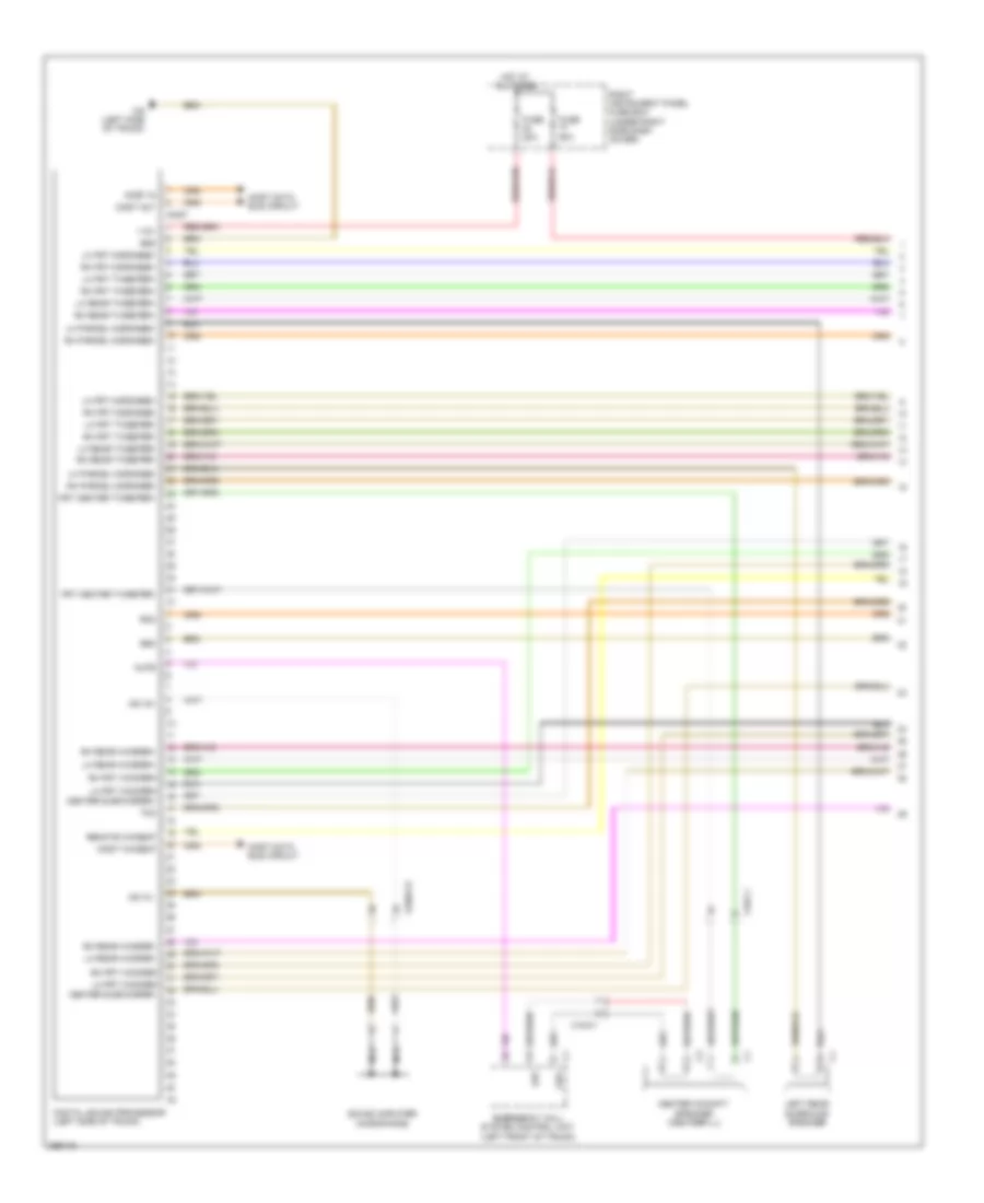
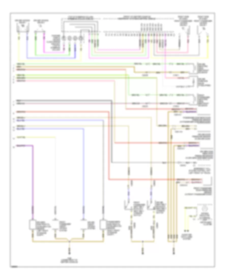
Automatic A/C Wiring Diagram (2 of 3) for Mercedes-Benz S550 2011
List of elements for Automatic A/C Wiring Diagram (2 of 3) for Mercedes-Benz S550 2011:
- (if equipped) a/c water valve
- (right rear of engine compt) aac multi-function sensor
- A/c (kla) 4-way sun sensor
- A/c air recirculation unit
- Air conditioning connector
- Blower motor
- Blower regulator
- Can-e h
- Can-e l
- Computer data lines system
- Coolant temperature sensor (5.5l: front of engine)
- Egs
- Electric suction fan engine & a/c w/ integrated control (behind center of radiator)
- Engine controls system
- Footwell)
- Heated windshield control unit (w/ special protection)
- Left b-pillar air distribution actuator motor (under left front seat)
- Left rear center air outlet actuator motor
- Me-sfi (me) control unit (right rear of engine compt)
- Pnk
- Red
- Refrigerant compressor
- Right b-pillar air distribution actuator motor (under right front seat)
- Right rear center air outlet actuator motor
- Vehicle interior humidity/ temperature sensor
- W/ humidity sensor
- W/ rear a/c
- W/o rear a/c
- W15 (right front computer data lines system
- W2 (right side of engine compt)
- X26-c1
- X53/1-c1
- X53/1-c3
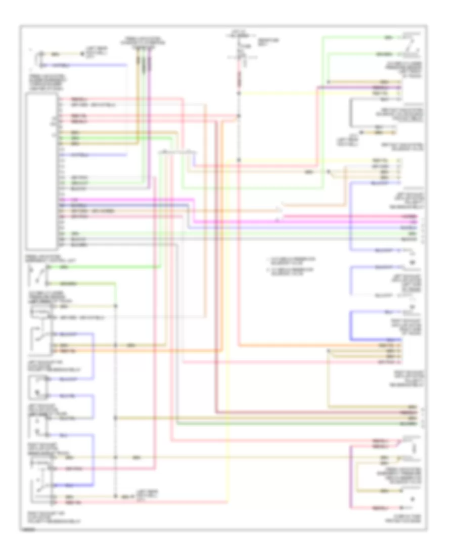
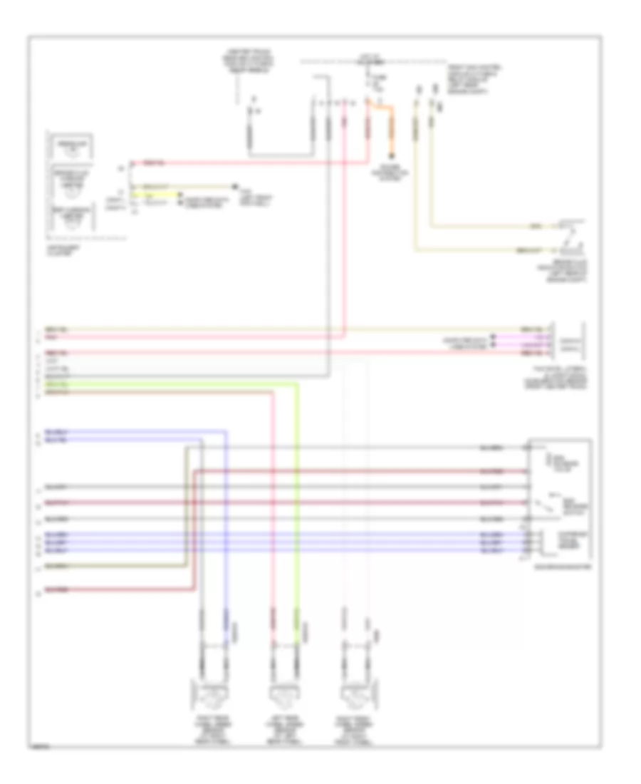
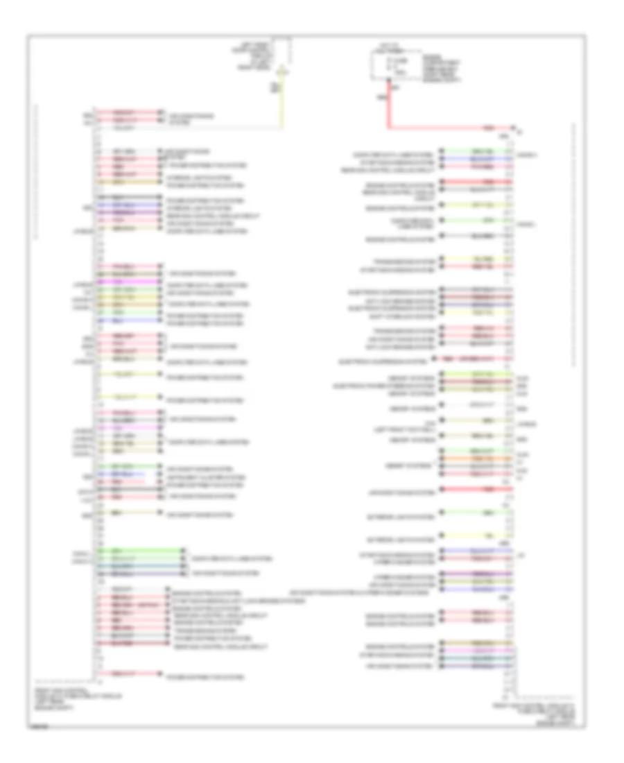
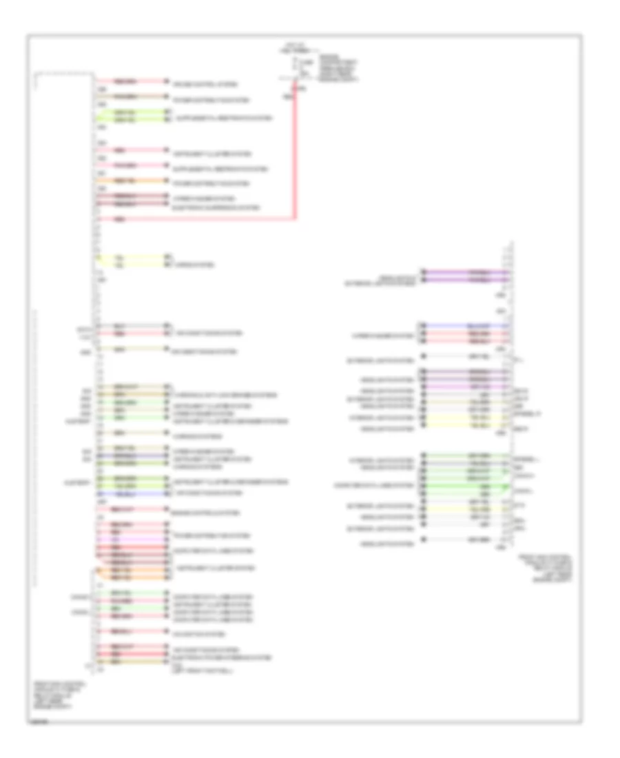
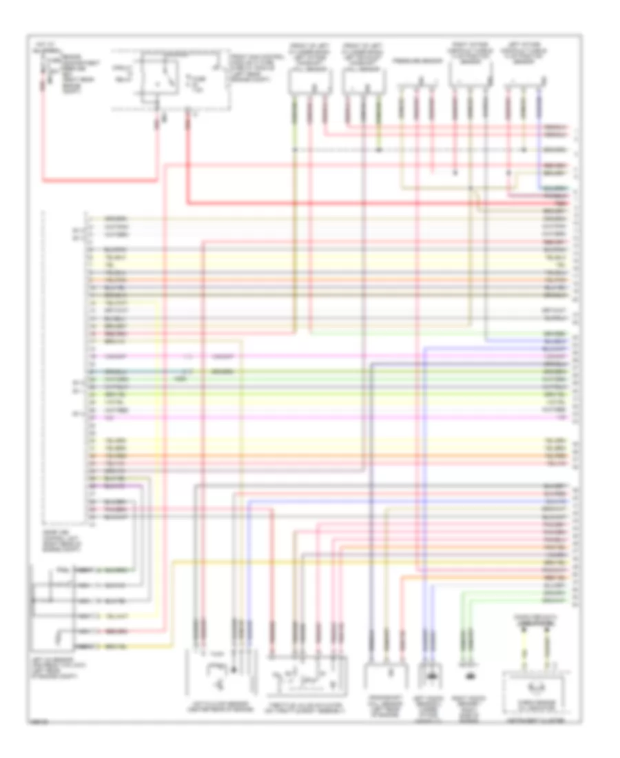
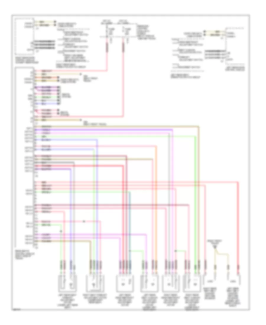
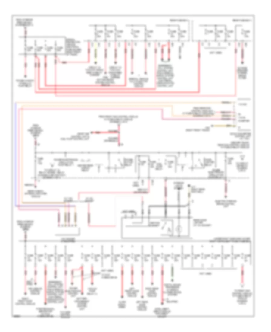
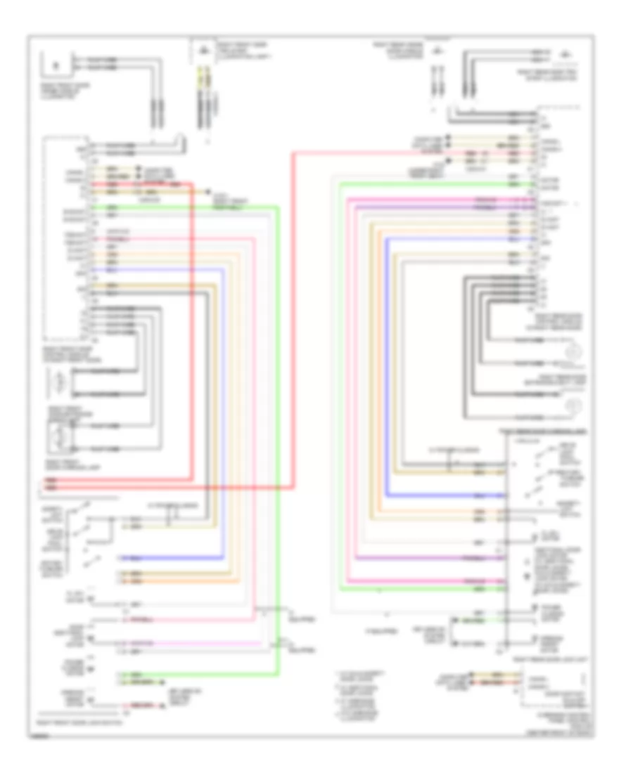
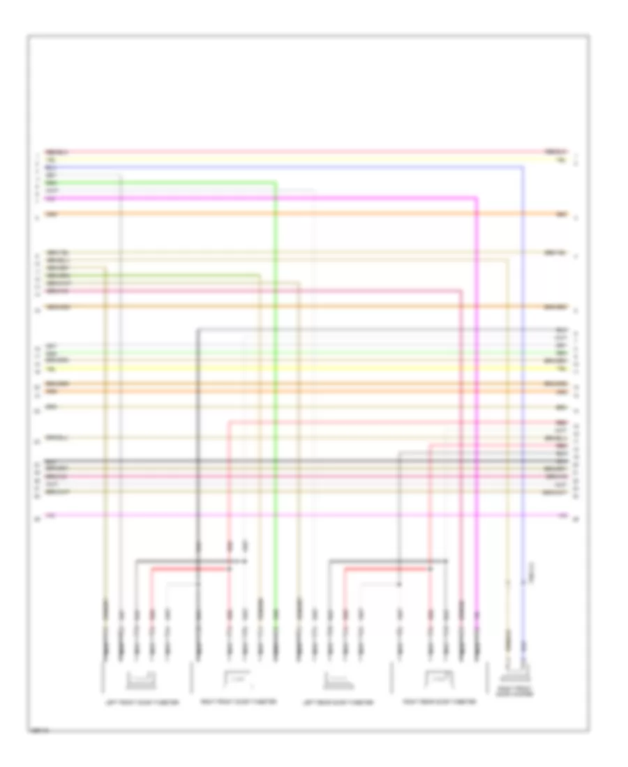
Automatic A/C Wiring Diagram (3 of 3) for Mercedes-Benz S550 2011
List of elements for Automatic A/C Wiring Diagram (3 of 3) for Mercedes-Benz S550 2011:
- (left center of dash) left side outlet temperature sensor
- (lower left side of hvac unit)
- (right center of dash) right side outlet temperature sensor
- (right front footwell)
- (right front footwell) w15/1
- (right of column steering under dash) evaporator temperature sensor
- (right side of dash) non-ventilated interior air in-car temperature cockpit sensor
- (right side under carriage) power electronics control unit
- (under left side of dash) left footwell temperature sensor
- (under right side of dash) right footwell temperature sensor
- 87f
- Battery management system control unit (right rear engine compt)
- Can-i h
- Can-i l
- Computer data lines system
- Dc/dc converter control module (right front wheelhouse)
- Electric refrigerant compressor (left front engine)
- Engine compartment prefuse box (right rear engine compt)
- Engine coolant circulation pump (right of radiator)
- Fresh air/ recirculated air flap actuator motor (right side of hvac unit)
- Fuse 100a
- Fuse 20a
- Fuse 60a
- Heater booster connector
- High voltage fuse box
- Hot at all times
- Hv +
- Hv -
- Interior prefuse box (right front footwell)
- Interlock in
- Interlock out
- Left center air flap actuator motor (left center of hvac unit)
- Left defroster vent flap actuator motor (top left side of hvac unit)
- Left footwell flap actuator motor (lower left center of hvac unit)
- Left side outlet flap actuator motor (top left center of hvac unit)
- Lower left blending air flap actuator motor
- Lower right blending air flap actuator motor (lower right side of hvac unit)
- Nca
- Pnk
- Ptc heater booster
- Red
- Right center air flap actuator motor (right center of hvac unit)
- Right defroster vent flap actuator motor (top right side of hvac unit)
- Right footwell flap actuator motor (lower right center of hvac unit)
- Right side outlet flap actuator motor (top right center of hvac unit)
- Upper left blending air flap actuator motor
- Upper right blending air flap actuator motor
- W15
- W3/2 (left side of engine compt)
- X73/2
Fresh Air Emergency System Wiring Diagram (1 of 2) for Mercedes-Benz S550 2011
List of elements for Fresh Air Emergency System Wiring Diagram (1 of 2) for Mercedes-Benz S550 2011:
- (left rear footwell) w7/1
- 15c
- C12
- Fresh air system buzzer emergency warning buzzer (center of dash)
- Fresh air system diagnostic interface connector
- Fresh air system emergency control unit
- Fresh air system emergency pressure medium reservoir solenoid valve
- Fuse 5a
- Hot at all times
- Irritant gas system solenoid valve
- Irritant gas system solenoid valve double contact relay
- Left exhaust air flap motor (left side of trunk)
- Left exhaust air flap motor polarity- reversing relay
- Left exhaust air flap motor polarity-reversing relay
- Overvoltage protection diode
- Oxygen cylinder pressure sensor (left front of trunk)
- Rear fuse box i
- Right exhaust air flap motor (right side of trunk)
- Right exhaust air flap motor polarity- reversing relay
- Right exhaust air flap motor polarity-reversing relay
- Solenoid valve
- W/ medium reservoir solenoid valve
- W/o medium reservoir
- W7/1 (left rear footwell)
Fresh Air Emergency System Wiring Diagram (2 of 2) for Mercedes-Benz S550 2011
List of elements for Fresh Air Emergency System Wiring Diagram (2 of 2) for Mercedes-Benz S550 2011:
- (not used)
- 58d
- Emergency vehicle system
- Fire extinguishing system control module
- Fire extinguishing system switch
- Fresh air sensor (right rear of engine compt)
- Fresh air system emergency activate button
- Fresh air system/fire extinguishing system emergency activate button
- Fresh air system/fire extinguishing system emergency activate button balance resistor
- Front sam control module w/ fuse & relay module (left rear engine compt)
- Mr8
- Nca
- Pas (gas) & special signal system control module (left front of trunk)
- Red
- Solenoid valve
- Special vehicle multifunction control module (svmcm (mss))
- W/ medium reservoir solenoid valve
- W/o medium reservoir
- W3/2 (left side of engine compt)
- Windshield washer fluid pump (right front of engine compt)
- X15/11
- X203
- X203/1
- X203/2
- X203/3
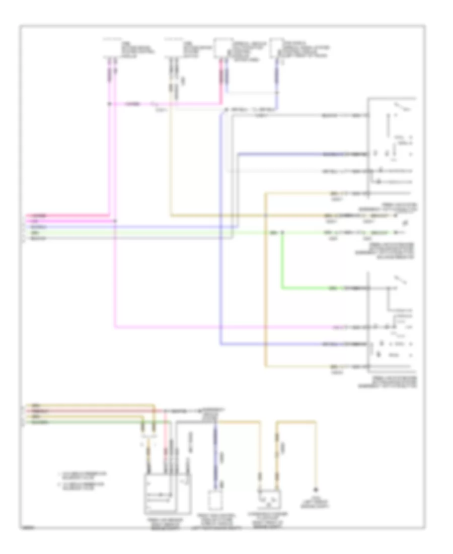
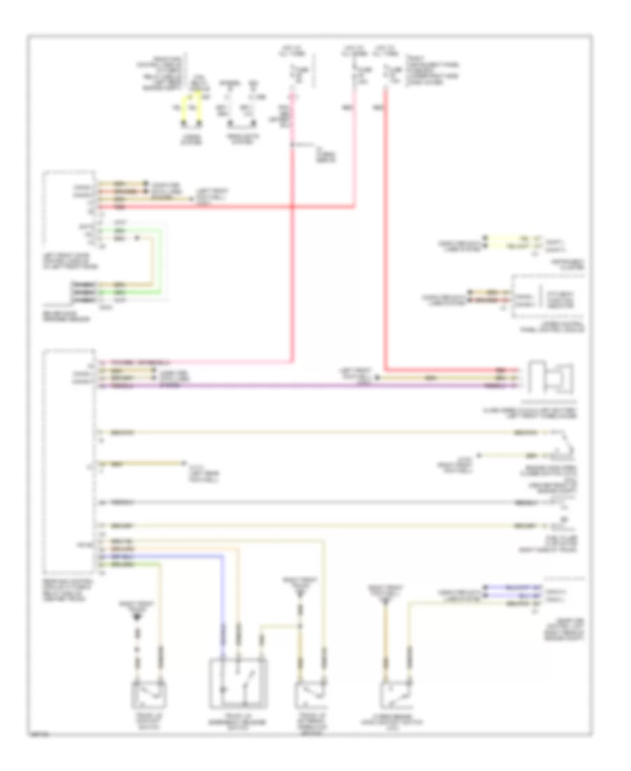
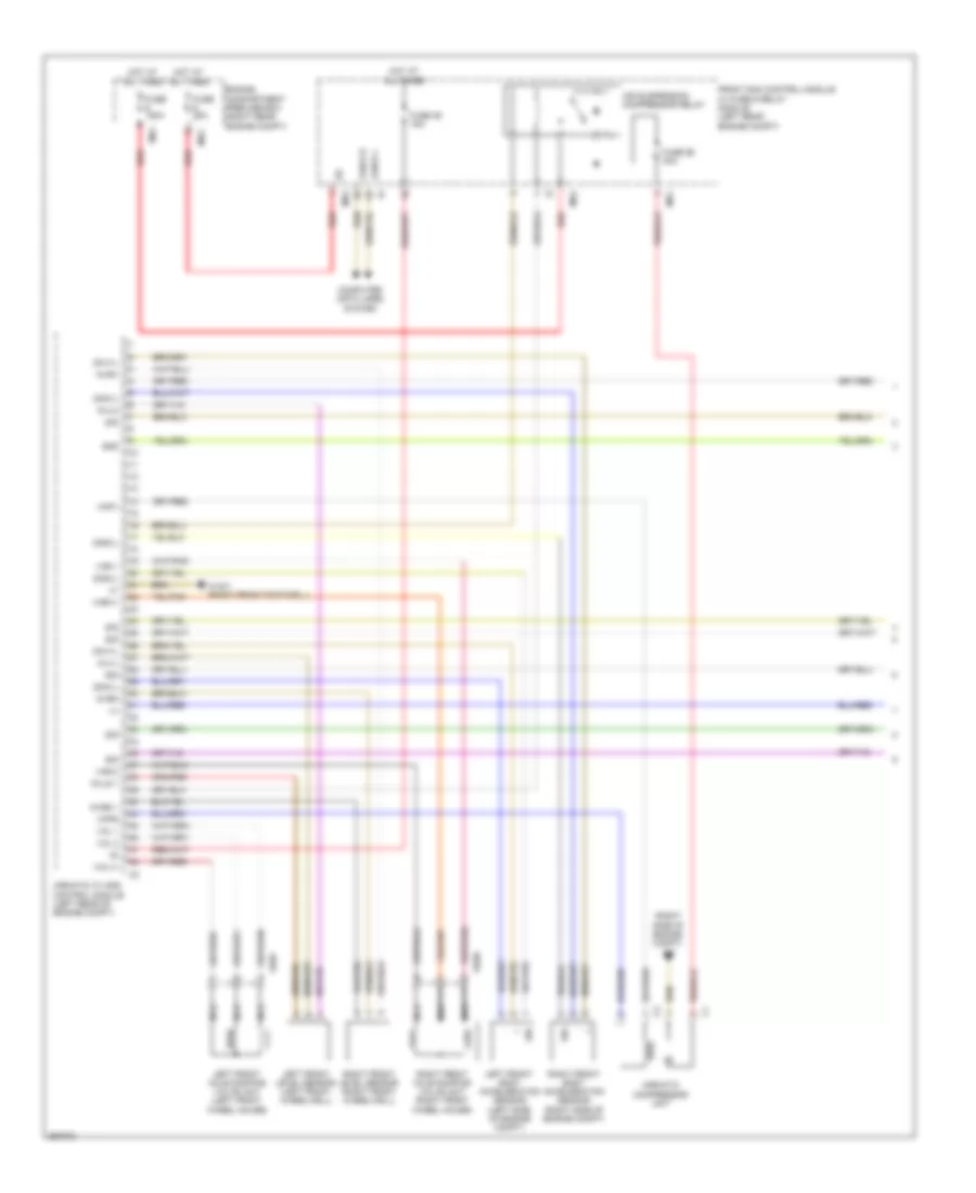
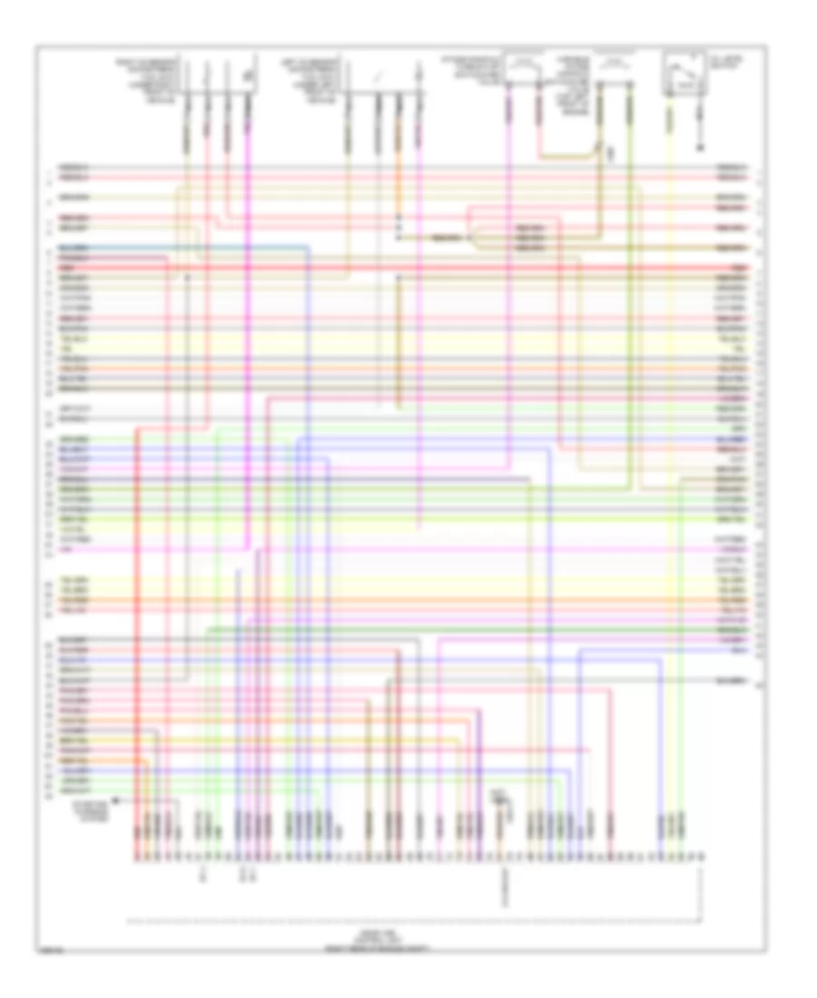
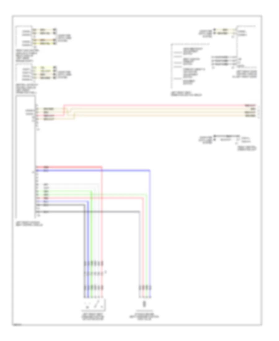
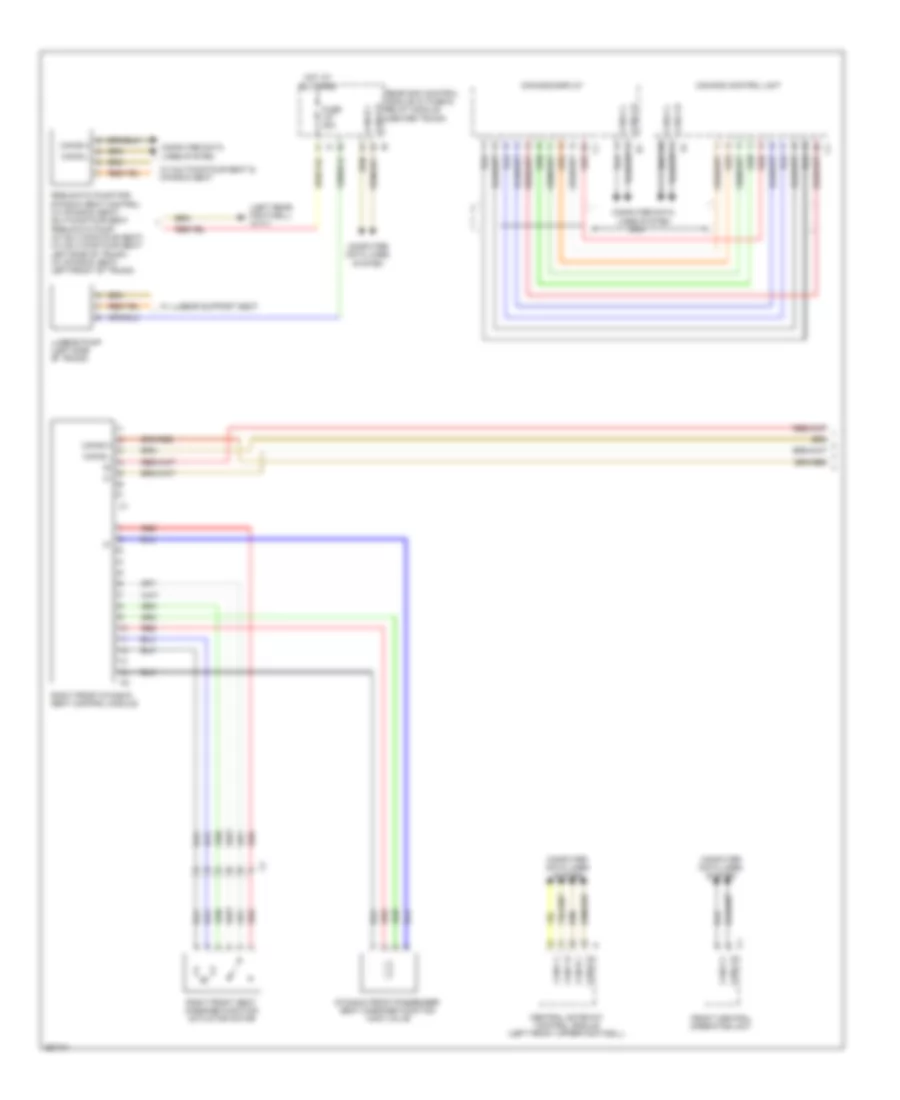
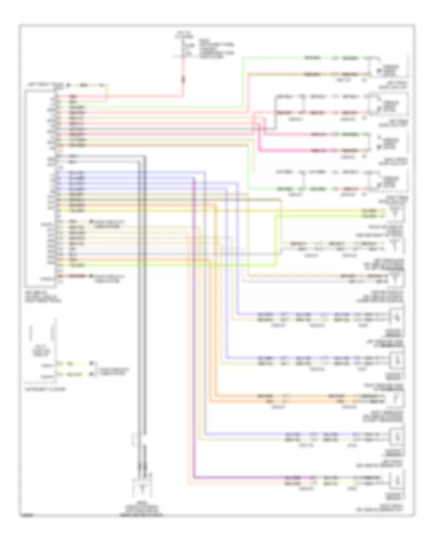
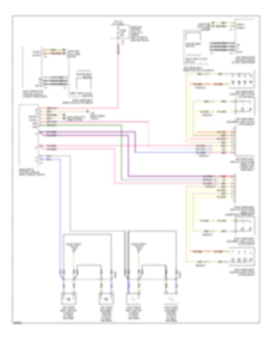
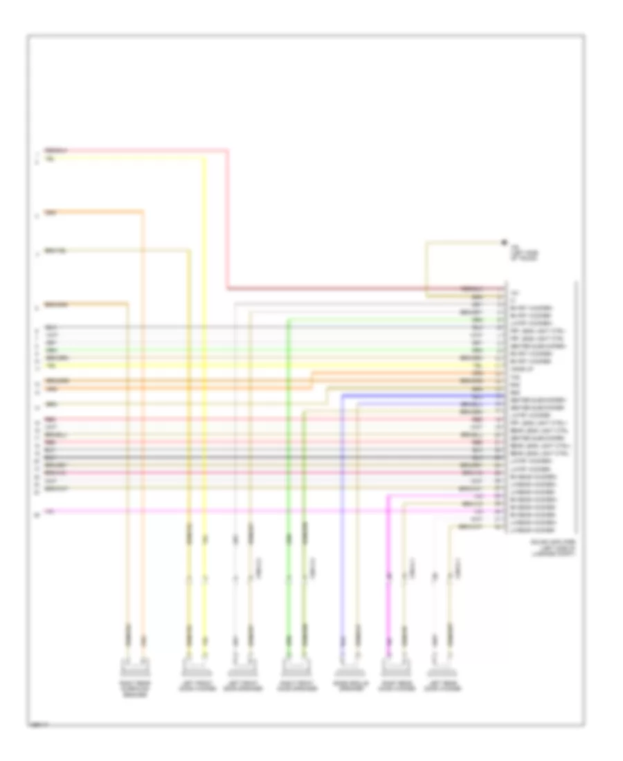
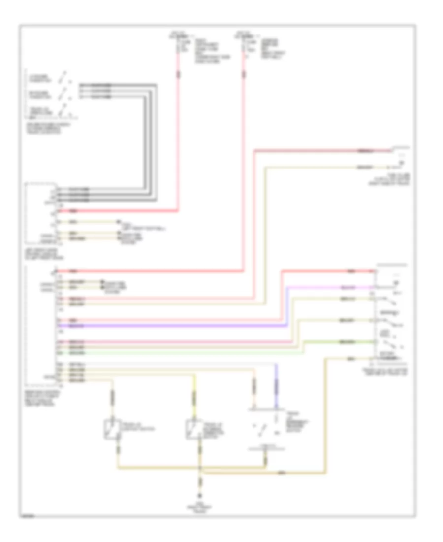
Rear A/C Wiring Diagram for Mercedes-Benz S550 2011
List of elements for Rear A/C Wiring Diagram for Mercedes-Benz S550 2011:
- (under left front seat) w18
- 12v
- Aac (kla) control unit (center dash)
- Can-a h
- Can-a l
- Can-b h
- Can-b l
- Can-e h
- Can-e l
- Computer data lines system
- Coolant circulation pump
- Coolant temperature sensor (5.5l: top front of engine)
- Egs
- Electric suction fan engine & a/c w/ integrated control (behind center of radiator)
- Engine compartment prefuse box (right rear engine compt)
- Engine controls system
- Front sam control module w/ fuse & relay module (left rear engine compt)
- Fuse 100a
- Fuse 15a
- Fuse 20a
- Fuse 5a
- Heated windshield control unit (w/ special protection)
- Hot at all times
- Hot w/ engine circuit 87 relay energized
- Left b-pillar air distribution actuator motor (under left front seat)
- Left duovalve
- Left instrument panel fuse box (under left side dash cover)
- Left rear air conditioning heater exchanger temperature sensor
- Left rear center air outlet actuator motor
- Lin (+)
- Lin (-)
- Lin bus
- Lin-data
- Me-sfi (me) control unit (right rear of engine compt)
- Pnk
- Rear a/c control module
- Rear a/c electronic blower regulator (in rear of center console)
- Rear blower motor (in rear of center console)
- Rear evaporator temperature sensor (rear of center console)
- Rear refrigerant shut-off valve (left front wheelhouse)
- Red
- Right b-pillar air distribution actuator motor (under right front seat)
- Right duovalve
- Right rear air conditioning heater exchanger temperature sensor
- Right rear center air outlet actuator motor
- W/ rear window defroster
- W/o rear window defroster
- W18 (under left front seat)
- W2 (right side of engine compt)
- X18-c4
- X53/1-c1
- X53/1-c3
- X64/10-c4
ANTI-LOCK BRAKES
Anti-lock Brakes Wiring Diagram (1 of 2) for Mercedes-Benz S550 2011
List of elements for Anti-lock Brakes Wiring Diagram (1 of 2) for Mercedes-Benz S550 2011:
- (right front engine compt) esp control module
- 12v
- Attention assist sensor (on steering column)
- Basic
- Bav a
- Bla
- Bls 12v
- Bls h
- Bls l
- Bls m
- Can e h
- Can e l
- Can h h
- Can h l
- Clu 12v
- Clu m
- Computer data lines system
- Df hl m
- Df hl s
- Df hr m
- Df hr s
- Engine compartment prefuse box (right rear engine compt)
- Front axle brake pressure sensor
- Front axle inlet solenoid valve
- Front axle switchover solenoid valve
- Fuse 25a
- Fuse 40a
- Fuse 7.5a
- High pressure & return pump
- Hot at all times
- Left front axle solenoid valve (hold)
- Left front axle solenoid valve (release)
- Left front pressure sensor
- Left front wheel speed sensor (at left front wheel)
- Left instrument panel fuse box (under left side dash cover)
- Left rear axle solenoid valve (hold)
- Left rear axle solenoid valve (release)
- Left rear pressure sensor
- Lrws 5v
- Lrws m
- Lrws sig
- Ls a
- Ls1
- Mp s
- Nca
- Pml 12v
- Pml a
- Pnk
- Premium
- Rear axle inlet solenoid valve
- Rear axle switchover solenoid valve
- Red
- Right front axle solenoid valve (hold)
- Right front axle solenoid valve (release)
- Right front pressure sensor
- Right rear axle solenoid valve (hold)
- Right rear axle solenoid valve (release)
- Right rear pressure sensor
- Sps (pml) solenoid valve
- Stop lamp switch (top of brake pedal assembly)
- Traction system hydraulic unit
- Ub s
- W/ basic
- W/ premium
- W14/3 (right front engine compt)
- X18-c2
- X62/7
Anti-lock Brakes Wiring Diagram (2 of 2) for Mercedes-Benz S550 2011
List of elements for Anti-lock Brakes Wiring Diagram (2 of 2) for Mercedes-Benz S550 2011:
- (center trunk) rear sam control module w/ fuse & relay module
- Abs/mil ind
- Bas brake booster
- Bas release switch
- Bas solenoid valve
- Brake fluid indicator switch (left rear of engine compt)
- Brake fluid warning lamp ind
- Can-f h
- Can-f l
- Can-h-h
- Can-h-l
- Computer data lines system
- Diaphragm travel sensor
- Esp warning lamp ind
- Front sam control module w/ fuse & relay module (left rear engine compt)
- Fuse 7.5a
- Gnd
- Hot at all times
- Instrument cluster
- Left rear wheel speed sensor (at left rear wheel)
- Mr7
- Nca
- Pnk
- Power distribution system
- Right front wheel speed sensor (at right front wheel)
- Right rear wheel speed sensor (at right rear wheel)
- Sig
- W43 (left front footwell)
- X62/32-d
- X62/33-d
- X62/6
- Yaw rate, lateral & longitudinal acceleration sensor (front center trunk)
ANTI-THEFT
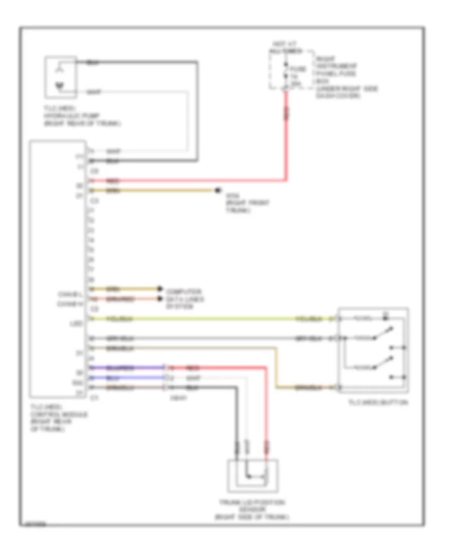
Anti-theft Alarm Wiring Diagram for Mercedes-Benz S550 2011
List of elements for Anti-theft Alarm Wiring Diagram for Mercedes-Benz S550 2011:
- (left front footwell) w34/1
- (right front footwell) w15/1
- (right front trunk) w54
- +5v
- 56a r
- Alarm siren w/auxiliary battery (left front wheelhouse)
- Ata (edw) function indicator
- Can-b h
- Can-b l
- Can-c h
- Can-c l
- Can-f h
- Can-f l
- Computer data lines system
- Data
- Driver door infrared sensor
- Engine hood open/ closed switch (ata) (5.5l) (center front of engine compt)
- Fan relay module
- Front sam control module w/ fuse & relay module (left rear engine compt)
- Fuel filler flap motor (right side of trunk)
- Fuse 40a
- Fuse 5a
- Fuse 7.5a
- Hd-as
- Headlights system
- Horns system
- Hot at all times
- Hybrid engine hood contact switch (3.5l)
- Instrument cluster
- Left front door control module (in left front door)
- Me-sfi (me) control unit (right rear of engine compt)
- Mr1
- Mr6
- Nca
- Pnk/red
- Rear sam control module w/ fuse & relay module (center trunk)
- Red
- Right instrument panel fuse box (under right side dash cover)
- Spiegel r
- Trunk lid contact switch
- Trunk lid emergency release switch
- Trunk lid external operation switch
- Upper control panel control module
- W/ hybrid derive
- W15/1 (right front footwell)
- W17/1 (left rear footwell)
- X8/34
Panic Alarm Wiring Diagram (1 of 2) for Mercedes-Benz S550 2011
List of elements for Panic Alarm Wiring Diagram (1 of 2) for Mercedes-Benz S550 2011:
- (+)
- (-)
- +12v
- +5v
- 15r
- 58d
- Authorities peripherals separation point
- C20
- Data +
- Data -
- Fire extinguishing control module
- Fuse 30a
- Hot at all times
- Interior speaker
- Left outside mirror microphone
- Mikro +
- Mikro -
- Nca
- Outside speaker
- Pas (gas) & special signal system control module (left front of trunk)
- Rear fuse box 1
- Red
- Right outside mirror microphone
- W7/1 (left rear footwell)
- X15/11
- X44/10
Panic Alarm Wiring Diagram (2 of 2) for Mercedes-Benz S550 2011
List of elements for Panic Alarm Wiring Diagram (2 of 2) for Mercedes-Benz S550 2011:
- (left rear footwell) w7/1
- 58d
- C1 police beacon separation point
- Fresh air system emergency active button
- Fresh air system/ fire extinguishing system emergency activate button balance resistor
- Interior lights system
- Left knee bolster emergency alarm active button
- Microphone separation point
- Nca
- Over voltage protection diode
- Rear fresh air outlet emergency alarm active button
- Red
- Right knee bolster emergency alarm active button
- Special signal system push button control module
- Special vehicle multi-function control module (svmcm (mss))
- W19 (under right front seat)
- X203/1
BODY CONTROL MODULES
Front SAM Control Module Wiring Diagram (1 of 2) for Mercedes-Benz S550 2011
List of elements for Front SAM Control Module Wiring Diagram (1 of 2) for Mercedes-Benz S550 2011:
- (or pnk)
- +12v
- +5v
- 12v
- 58d
- Air conditioning system
- Air conditioning system & wiper/washer systems
- Anti-lock brakes system
- Can-b h
- Can-b l
- Can-c h
- Can-c l
- Can-e h
- Can-e l
- Computer data lines system
- Data
- Electronic power steering system
- Electronic suspension system
- Engine compartment prefuse box (right rear engine compt)
- Engine controls system
- Exterior lights system
- Front sam control module w/ fuse & relay module (left rear engine compt)
- Fuse 150a
- Gnd
- Hot at all times
- Instrument cluster system
- Interior lights system
- Left front door control module (in left front door)
- Lin
- Lin-bus
- Memory systems
- Mls+
- Mls-
- Mr1
- Mr4
- Mr8
- Mr9
- Pnk
- Pnk/red
- Power distribution system
- Rear sam control module circuit
- Red
- Shift interlock system
- Starting/charging & anti-lock brakes systems
- Starting/charging system
- Transmissions system
- W34 (left front footwell)
- Wiper/washer system
Front SAM Control Module Wiring Diagram (2 of 2) for Mercedes-Benz S550 2011
List of elements for Front SAM Control Module Wiring Diagram (2 of 2) for Mercedes-Benz S550 2011:
- +12v
- 49a r
- 49al
- 52a
- 55r
- 56a r
- 56al
- 56d
- 56d r
- 57 l
- 57 r
- Air conditioning system
- Austemp+
- Austemp-
- C60
- C61
- C62
- C63
- C64
- C65
- C66
- Can-e h
- Can-e l
- Can-g h
- Can-g l
- Computer data lines system
- Cruise control system
- Data
- Electronic power steering system
- Electronic suspension system
- Engine compartment prefuse box (right rear engine compt)
- Engine controls system
- Exterior lights system
- Front sam control module w/ fuse & relay module (left rear engine compt)
- Fuse 25a
- Gnd
- Headlights & exterior lights systems
- Headlights system
- Horns system
- Hot at all times
- Instrument cluster & defogger systems
- Instrument cluster system
- Interior lights system
- Mr1
- Mr2
- Mr3
- Mr5
- Mr6
- Mr7
- Navigation system
- Pnk/red
- Power distribution system
- Red
- Sig
- Spiegel l
- Spiegel r
- W34 (left front footwell)
- Warning & anti-lock brakes systems
- Warning systems
- Wiper/washer system
Rear SAM Control Module Wiring Diagram for Mercedes-Benz S550 2011
List of elements for Rear SAM Control Module Wiring Diagram for Mercedes-Benz S550 2011:
- (left rear engine compt)
- (left rear footwell) w17/1
- 3 bl
- Anti-theft system
- Bi l
- Bi r
- Bsl l
- Bsl r
- Can-b h
- Can-b l
- Computer data lines system
- Cruise control system
- Defogger system
- Engine controls system
- Exterior lights system
- Front sam control module w/ fuse & relay module (3.5l)
- Fuse 150a
- Gk l
- Gk r
- Hd as
- Headlights system
- Hot at all times
- Hs +
- Hs -
- Hs 1
- Hs 2
- I10
- Ig3
- Instrument cluster & mirrors systems
- Instrument cluster system
- Interior lights system
- Interior prefuse box (right front footwell)
- Kzl l
- Memory systems
- Navigation & sound systems
- Navigation system
- Nsl l
- Nsl r
- Passive restraint system
- Pnk/red
- Power distribution system
- Power tops system
- Power windows system
- Rear sam control module w/ fuse & relay module (center trunk)
- Red
- Rfl l
- Seats & memory systems
- Shift interlock system
- Sig
- Sound systems
- Trunk, tailgate, fuel doors system
- Volume control intermediate connector (w/ dvd) power windows system
- W54/3 (left front trunk)
- Warning systems
COMPUTER DATA LINES
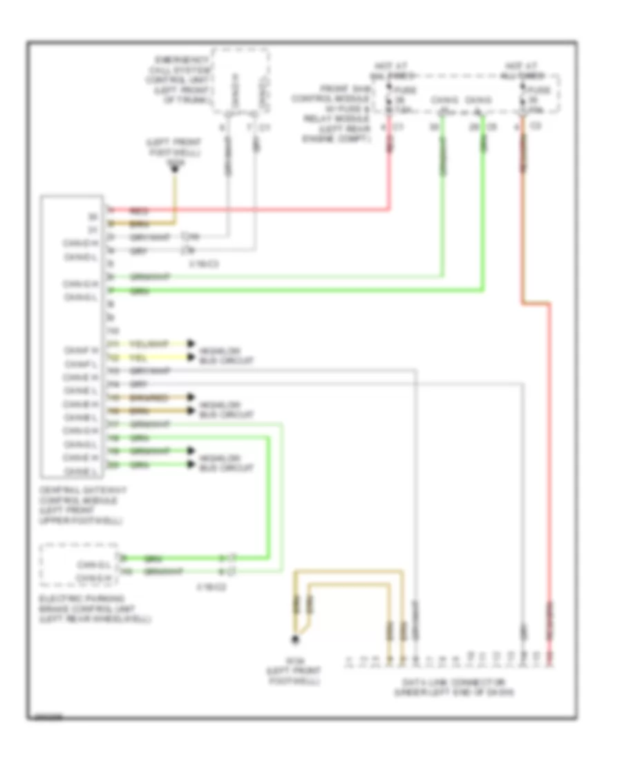
Data Link Connector Wiring Diagram for Mercedes-Benz S550 2011
List of elements for Data Link Connector Wiring Diagram for Mercedes-Benz S550 2011:
- (left front footwell) w34
- Can-b h
- Can-b l
- Can-d h
- Can-d l
- Can-e h
- Can-e l
- Can-f h
- Can-f l
- Can-g h
- Can-g l
- Central gateway control module (left front upper footwell)
- Data link connector (under left end of dash)
- Electric parking brake control unit (left rear wheelwell)
- Emergency call system control unit (left front of trunk)
- Front sam control module w/ fuse & relay module (left rear engine compt)
- Fuse 10a
- Fuse 7.5a
- High/low bus circuit
- Hot at all times
- Red
- W34 (left front footwell)
- X18-c2
- X18-c3
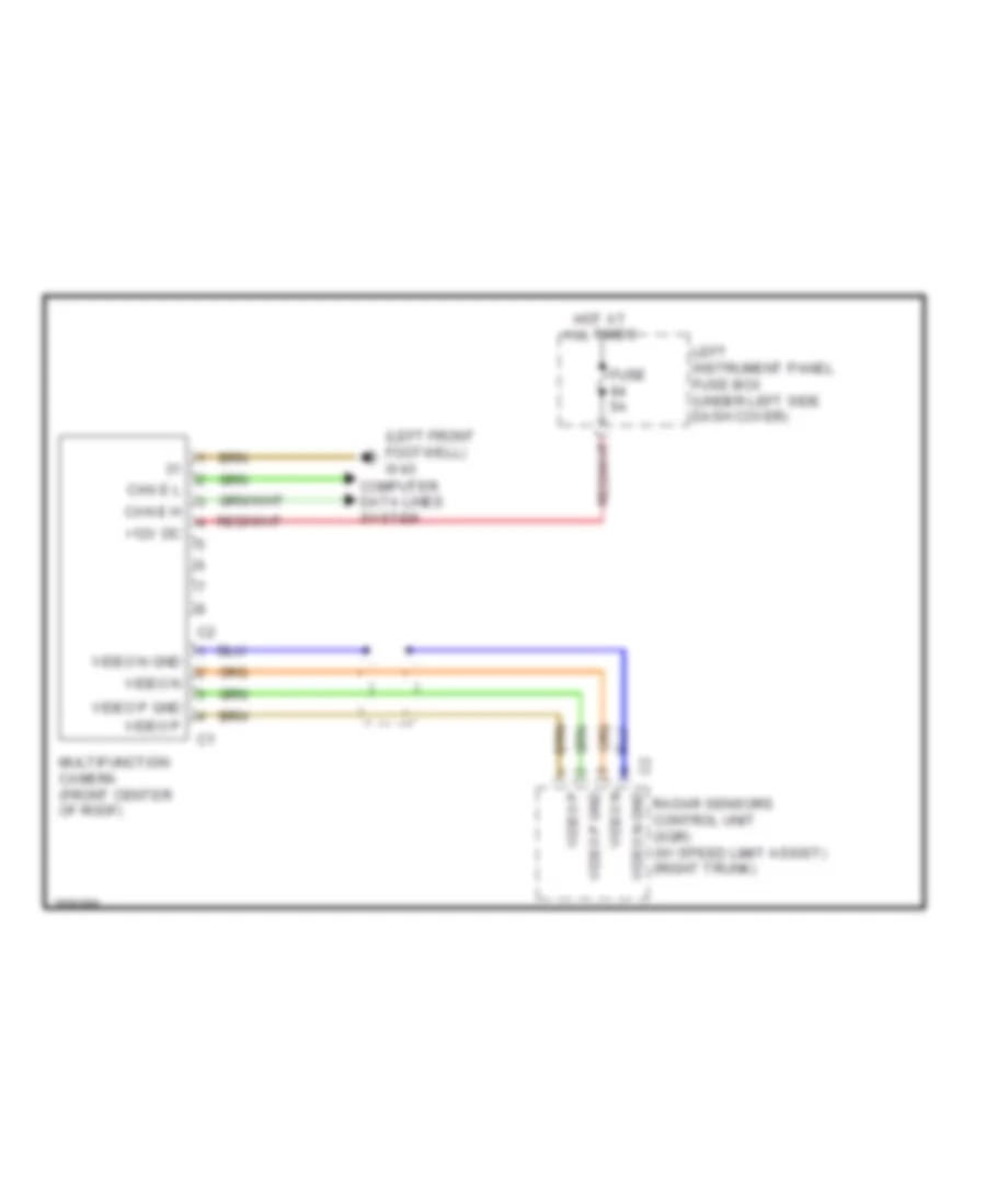
High/Low Bus Wiring Diagram (1 of 4) for Mercedes-Benz S550 2011
List of elements for High/Low Bus Wiring Diagram (1 of 4) for Mercedes-Benz S550 2011:
- Battery management system control unit (right rear engine compt)
- Can-c h
- Can-c l
- Can-f h
- Can-f l
- Can-h h
- Can-h l
- Can-i h
- Can-i l
- Central can voltage distributor connector
- Central gateway control module (left front upper footwell)
- Comand control unit
- Dc/dc converter control module (right front wheelhouse)
- Direct select intelligent servo module for (if equipped) (transmission housing)
- Drivetrain can voltage distributor connector
- Dtr control unit (if equipped) (under plate in right front footwell)
- Electric control unit (vgs)
- Electric refrigerant compressor (left front engine)
- Esp control module (5.5l) regenerative braking system control unit (3.5l hybrid) (right front engine compt)
- Hybrid can voltage distributor connector (3.5l hybrid)
- Instrument cluster
- Me-sfi (me) control unit (right rear of engine compt)
- Power electronics control unit (right side undercarriage)
- Radar sensor system control unit (w/ distance plus) video & radar sensor system control unit (w/ distronics plus) (right side of trunk)
- Vehicle dynamics can voltage distributor connector
- W18 (under left front seat)
- W34/1 (left front footwell)
- X18-c1
- X26/29
- Yaw rate, lateral & longitudinal acceleration sensor (front center trunk)
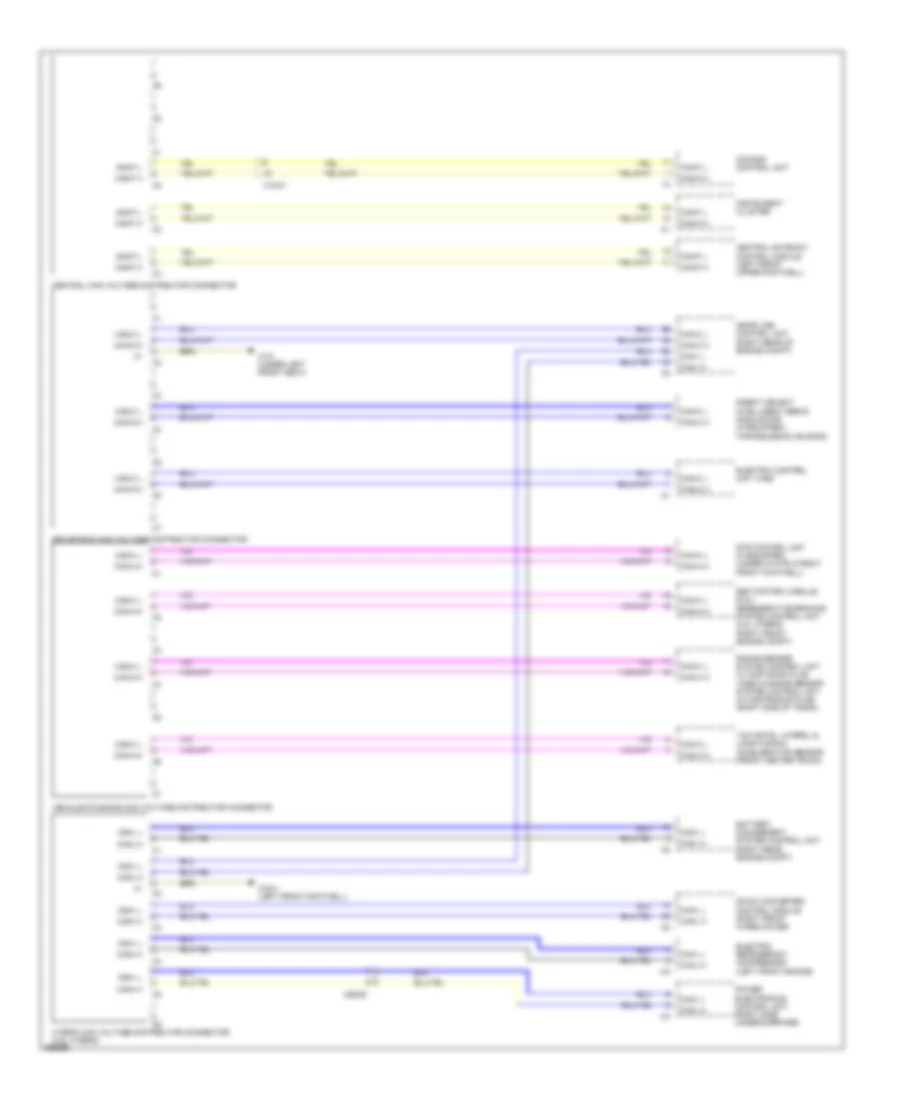
High/Low Bus Wiring Diagram (2 of 4) for Mercedes-Benz S550 2011
List of elements for High/Low Bus Wiring Diagram (2 of 4) for Mercedes-Benz S550 2011:
- Abc control module (left rear of engine compt)
- Airmatic w/ ads control module (left rear of engine compt)
- C10
- C11
- C12
- C13
- Can
- Can-e h
- Can-e l
- Central gateway control module (left front upper footwell)
- Chassis can/cockpit voltage distributor connector
- Chassis can/ffs (rba) voltage distributor connector
- Eis (ezs) control unit
- Electrohydraulic power steering (right front engine compt)
- Esp control module (5.5l) regenerative braking system control module (3.5l hybrid) (right front engine compt)
- Front sam control module w/ fuse & relay module (left rear engine compt)
- Left front reversible emergency tensioning retractor (base of left front "b" pillar)
- Me-sfi (me) control module (right rear of engine compt)
- Multi-function camera (if equipped) (front center of proof)
- Night vision assist control unit (if equipped) (left front footwell)
- Pts control module (if equipped) (right side trunk)
- Restraint systems control module (front of center console)
- Right front reversible emergency tensioning retractor (base of right front "b" pillar)
- Steering column module (top of steering column)
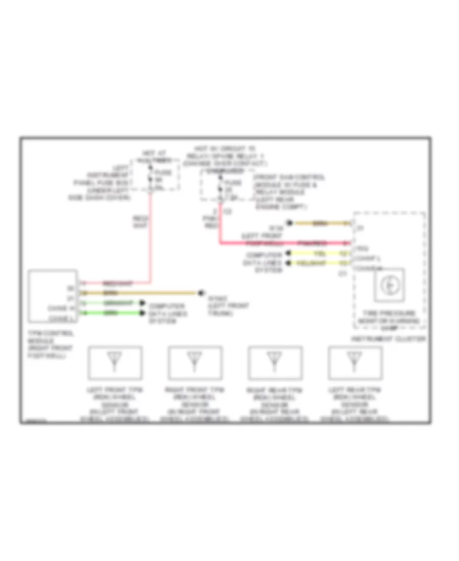
- Tpm control module (right front footwell)
- Video & radar sensor control unit (w/ distronics plus) radar sensors control unit (sgr) (w/ distance plus) (right side of trunk)
- W/ abc
- W/ airmatic
- W15/1 (right front footwell)
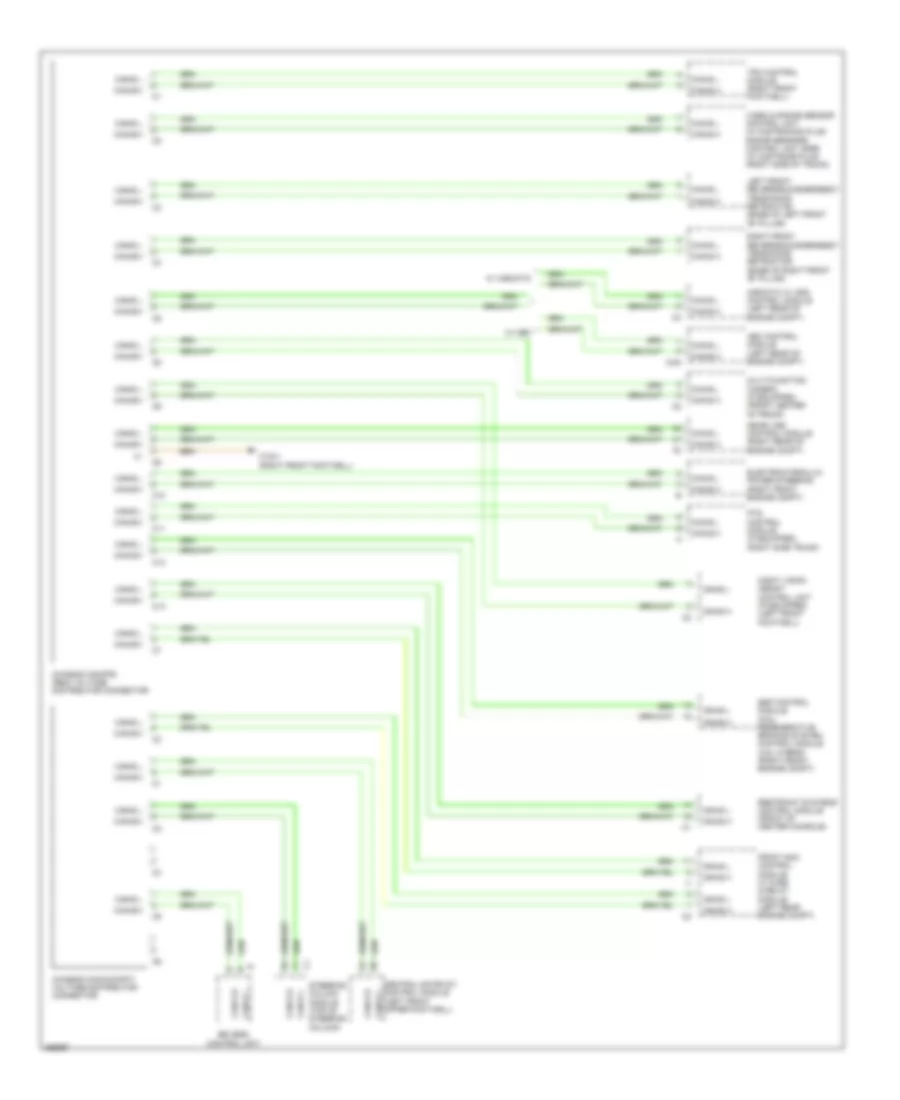
High/Low Bus Wiring Diagram (3 of 4) for Mercedes-Benz S550 2011
List of elements for High/Low Bus Wiring Diagram (3 of 4) for Mercedes-Benz S550 2011:
- Aac (kla) control unit (center dash)
- Backup camera control unit (if equipped)
- C10
- C11
- C12
- C13
- Can-b h
- Can-b l
- Central gateway control module (left front upper footwell)
- Eis (ezs) control unit
- Front sam control module w/ fuse & relay module (left rear engine compt)
- Interior can/cockpit voltage distributor connector
- Keyless go control unit (if equipped) (right rear trunk)
- Left front door control module (in left front door)
- Left front seat control module
- Left interior can/ffs (rba) voltage distributor connector
- Left rear door control module (in left rear door)
- Left rear multicontour backrest control module (if equipped)
- Pneumatic pump for dyanamic seat control (w/ dynamic seat ds (fds)) (left front of trunk)
- Rear sam control module w/ fuse & relay module (center trunk)
- Right rear multicontour backrest control module (if equipped)
- Upper control panel control module
- X35/3-c1
High/Low Bus Wiring Diagram (4 of 4) for Mercedes-Benz S550 2011
List of elements for High/Low Bus Wiring Diagram (4 of 4) for Mercedes-Benz S550 2011:
- (front of roof)
- C10
- C11
- C12
- C13
- Can-a h
- Can-a l
- Can-b h
- Can-b l
- Comand control unit
- Comand display (w/o split view display) comand display & split view display (w/ split view display)
- Front central operating unit
- Overhead control panel control module (center front of roof)
- Panoramic sliding roof control module (if equipped)
- Pts control module (right side trunk)
- Rcp (hbf) control module
- Rear ac control module (if equipped)
- Rear seats control module (right side of trunk)
- Right front door control module (in right front door)
- Right front seat control module
- Right interior can/ffs (rba) voltage distributor connector
- Right rear door control module (in right rear door)
- Special vehicle multifunction control module (svmcm (mss)) (if equipped)
- Telematics can voltage distributor connector
- Tlc (hds) control module (w/ remote trunk locking) (right rear trunk)
- Tpm control module (if equipped) (right front footwell)
- W15/1 (right front footwell)
- W19 (under right front seat)
- Weight sensing system (wss) control unit (right front seat)
- X18-c1
- X25/8-c3
- X25/8-c4
- X28/30
- X35/2-c5
- X35/4-c1
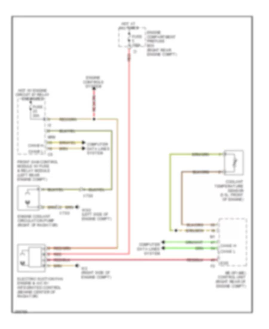
COOLING FAN
Cooling Fan Wiring Diagram for Mercedes-Benz S550 2011
List of elements for Cooling Fan Wiring Diagram for Mercedes-Benz S550 2011:
- Can-b h
- Can-b l
- Can-e h
- Can-e l
- Computer data lines system
- Coolant temperature sensor (5.5l: front of engine)
- Egs
- Electric suction fan engine & a/c w/ integrated control (behind center of radiator)
- Engine compartment prefuse box (right rear engine compt)
- Engine controls system
- Engine coolant circulation pump (right of radiator)
- Front sam control module w/ fuse & relay module (left rear engine compt)
- Fuse 100a
- Fuse 20a
- Hot at all times
- Hot w/ engine circuit 87 relay energized
- Me-sfi (me) control unit (right rear of engine compt)
- Mr8
- Red
- W2 (right side of engine compt)
- W3/2 (left side of engine compt)
- X73/2
CRUISE CONTROL
Cruise Control Wiring Diagram for Mercedes-Benz S550 2011
List of elements for Cruise Control Wiring Diagram for Mercedes-Benz S550 2011:
- (pins: 17 to 32 not used)
- (top of steering column) steering column module
- 3.5l
- 5.5l
- A4 4ip
- Accel/ set
- Accelerator pedal sensor (top of accelerator pedal assembly)
- At dcm
- At dcp
- C135
- C142
- Can-e h
- Can-e l
- Can-h h
- Can-h l
- Can-s-h
- Can-s-l
- Computer data lines system
- Control contact
- Cruise control switch
- Decel/ set
- Dtr distance potentiometer (if equipped)
- Ea ip1s
- Ea ip2s
- Front bumper left inner radar sensor
- Front bumper right inner radar sensor
- Front sam control module w/ fuse & relay module (left rear engine compt)
- Fuse 10a
- Fuse 7.5a
- Gnd
- Hot at all times
- Hot in on or start
- Me-sfi (me) control module (right rear of engine compt)
- Mr ipm
- Multi-function camera (w/ speed limit assist) (front center of roof)
- Off
- Pwg+
- Pwg1-0
- Pwg1-1
- Pwg2-0
- Pwg2-1
- Radar sensors control unit (sgr) (right trunk)
- Rear bumper left outer radar sensor
- Rear bumper right outer radar sensor
- Rear pts warning display (w/ city assist)
- Rear sam control module w/ fuse & relay module (center trunk)
- Red
- Resume from memory
- Throttle valve actuator (on throttle body assembly)
- Video n
- Video n gnd
- Video p
- Video p gnd
- W/ distronic plus
- W/ multi function camera
- W/o multi function camera
- W17/1 (left rear footwell)
- W34 (left front footwell)
- W34/1 (left front footwell)
- W7/1 (left rear footwell)
- X213/1
- X213/2
- X25/8-c3
Electronic Accelerator/Cruise/Idle Speed Control Wiring Diagram for Mercedes-Benz S550 2011
List of elements for Electronic Accelerator/Cruise/Idle Speed Control Wiring Diagram for Mercedes-Benz S550 2011:
- (under plate in right front footwell) dtr control unit
- 58d
- Automatic child seat recognition air bag off ind lamp
- C66
- Can-b h
- Can-b l
- Can-c h
- Can-c l
- Can-f h
- Can-f l
- Can-h h
- Can-h l
- Cockpit switch group
- Comand display dimmer brightness control
- Comand display swivel left switch
- Comand display swivel right switch
- Computer data lines system
- Dtr control unit
- Dtr radar sensor
- Dtr warning lamp ind
- Electric control unit (vgs)
- Esp off switch
- Exterior lights & instrument cluster system
- Freely programmable button
- Front central operating unit
- Front sam control module w/ fuse & relay module (left rear engine compt)
- Fuse 7.5a
- Hazard warning system button
- Hot at all times
- Hot w/ chasis circuit 87 relay energized
- Instrument cluster
- Level adjustment switch
- Me-sfi (me) control module (right rear of engine compt)
- Output
- Pts off switch
- Red
- Sig
- Speed sensor
- Switch & controls illumination/ night vision assist display dimmer brightness control
- Upper control panel control unit
- W3/1 (right side of engine compt)
- W34 (left front footwell)
- X18-c1
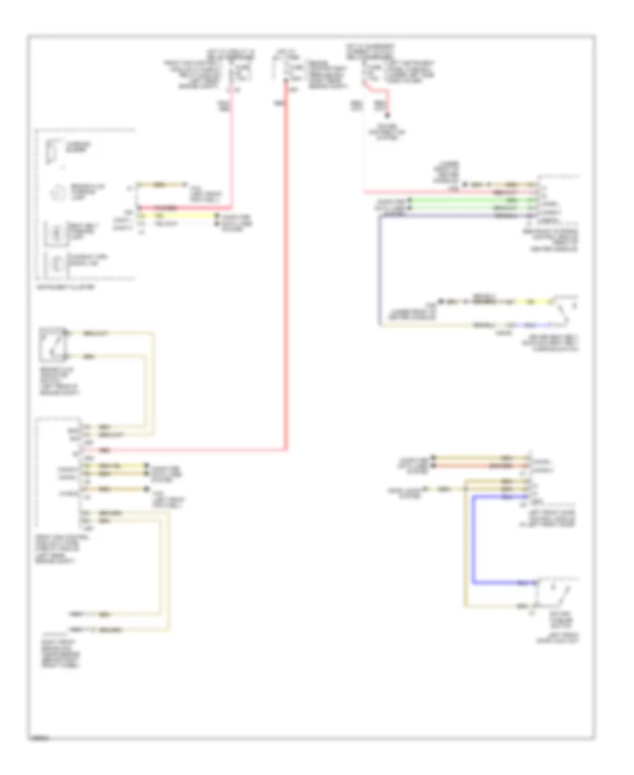
DEFOGGERS
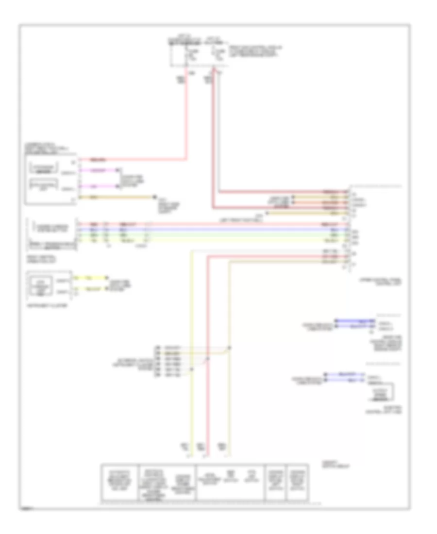
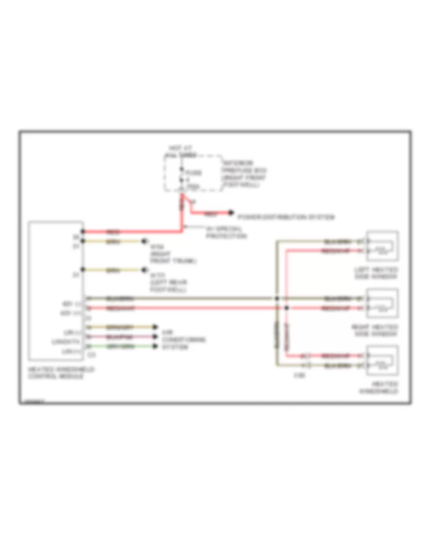
Heated Windshield Wiring Diagram for Mercedes-Benz S550 2011
List of elements for Heated Windshield Wiring Diagram for Mercedes-Benz S550 2011:
- 42v (+)
- 42v (-)
- Air conditioning system
- Fuse 150a
- Heated windshield
- Heated windshield control module
- Hot at all times
- Interior prefuse box (right front footwell)
- Left heated side window
- Lin (+)
- Lin (-)
- Lin-data
- Power distribution system
- Red
- Right heated side window
- W/ special protection
- W54 (right front trunk)
- W7/1 (left rear footwell)
- X92
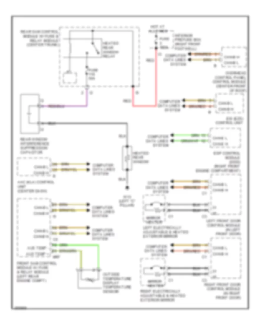
Rear Defogger Wiring Diagram for Mercedes-Benz S550 2011
List of elements for Rear Defogger Wiring Diagram for Mercedes-Benz S550 2011:
- Aac (kla) control unit (center dash)
- Aus temp +
- Aus temp -
- Can-b h
- Can-b l
- Can-e h
- Can-e l
- Computer data lines system
- Eis (ezs) control unit
- Esp control module (s550) (right front engine compartment)
- Front sam control module w/ fuse & relay module (left rear engine compt)
- Fuse 150a
- Fuse 50a
- Heated rear window
- Heated rear window relay
- Hot at all times
- Interior prefuse box (right front footwell)
- Left electrically adjustable & heated exterior mirror
- Left front door control module (in left front door)
- Mirror heater
- Mr7
- Outside temperature display temperature sensor
- Overhead control panel control module (center front of roof)
- Rear sam control module w/ fuse & relay module (center trunk)
- Rear window interference suppression capacitor
- Red
- Right electrically adjustable & heated exterior mirror
- Right front door control module (in right front door)
- W13 (left "c" pillar)
ELECTRONIC POWER STEERING
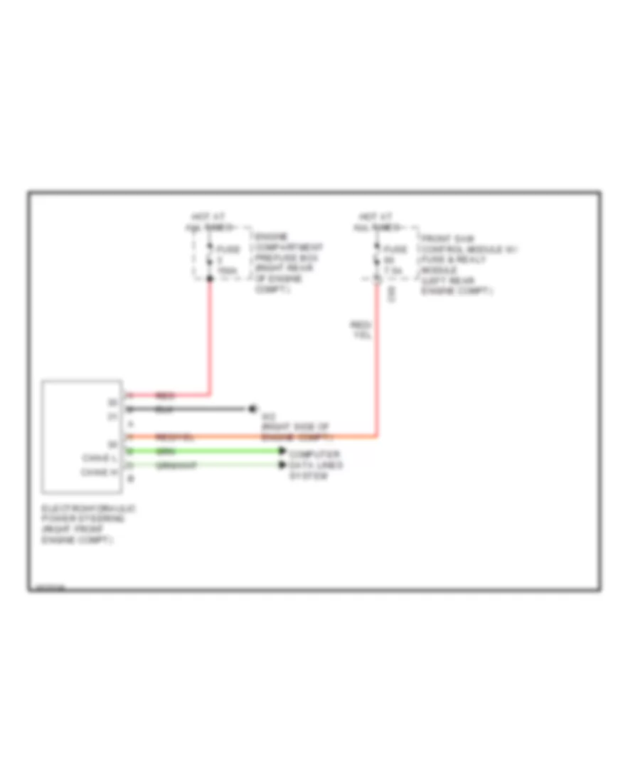
Electro Hydraulic Power Steering Wiring Diagram for Mercedes-Benz S550 2011
List of elements for Electro Hydraulic Power Steering Wiring Diagram for Mercedes-Benz S550 2011:
- C60
- Can-e h
- Can-e l
- Computer data lines system
- Electrohydraulic power steering (right front engine compt)
- Engine compartment prefuse box (right rear of engine compt)
- Front sam control module w/ fuse & realy module (left rear engine compt)
- Fuse 150a
- Fuse 7.5a
- Hot at all times
- Red
- W2 (right side of engine compt)
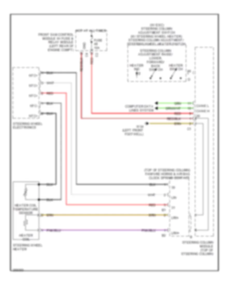
Power Steering Column Wiring Diagram for Mercedes-Benz S550 2011
List of elements for Power Steering Column Wiring Diagram for Mercedes-Benz S550 2011:
- (if equipped) heater coil
- (on steering column) steering angle sensor
- Accelerate & set switch
- Accept/terminate phone call pushbutton
- Aldw+
- Aldw-
- Back & sbs off button
- Can-e h
- Can-e l
- Combination switch
- Computer data lines system
- Control contact switch
- Cruise control switch
- Decelerate & set switch
- Dtr distance potentiometer (if equipped)
- Fanfare horns & air bag clock spring contact (top of steering column)
- Fanfare horns pushbutton
- Front sam control module w/ fuse & relay module (left rear engine compt)
- Fuse 10a c2
- Gear selector switch direct select
- Gnd
- Head lamp flasher/high beam switch
- Heater coil temperature sensor (if equipped)
- Hot at all times
- Left & right turn signal switch
- Left multi-function steering wheel pushbutton group
- Low beam switch
- Lsp+
- Lsp-
- Mute button
- Nca
- Ntc +
- Ntc -
- Ntc+
- Off switch
- Ok button
- Pushbutton + & - setting of specific functions & volume control
- Red
- Resume from memory switch
- Right multi-function steering wheel pushbutton group
- Scroll forward/ back pushbutton
- Steering column adjustment switch
- Steering column adjustment switch (w/ esc (elv)) steering column adjustment/ steering wheel heater switch (w/ steering wheel heater)
- Steering column module (top of steering column)
- Steering lock switch
- Steering wheel electronics
- Steering wheel gear shifter (+) (if equipped)
- Steering wheel gear shifter (-) (if equipped)
- Steering wheel heater function indicator lamp (if equipped)
- Steering wheel heater switch (if equipped)
- Steering wheel vibration motor (w/ automatic lane recognition)
- System selection pushbutton
- Vcs (sbs) on button
- W/ steering wheel heater
- W34 (left front footwell)
- Windshield washer system switch
- Wipe switch
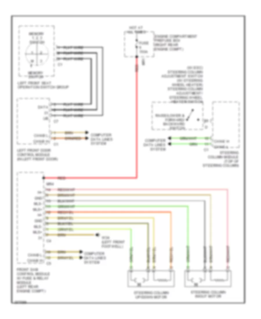
ELECTRONIC SUSPENSION
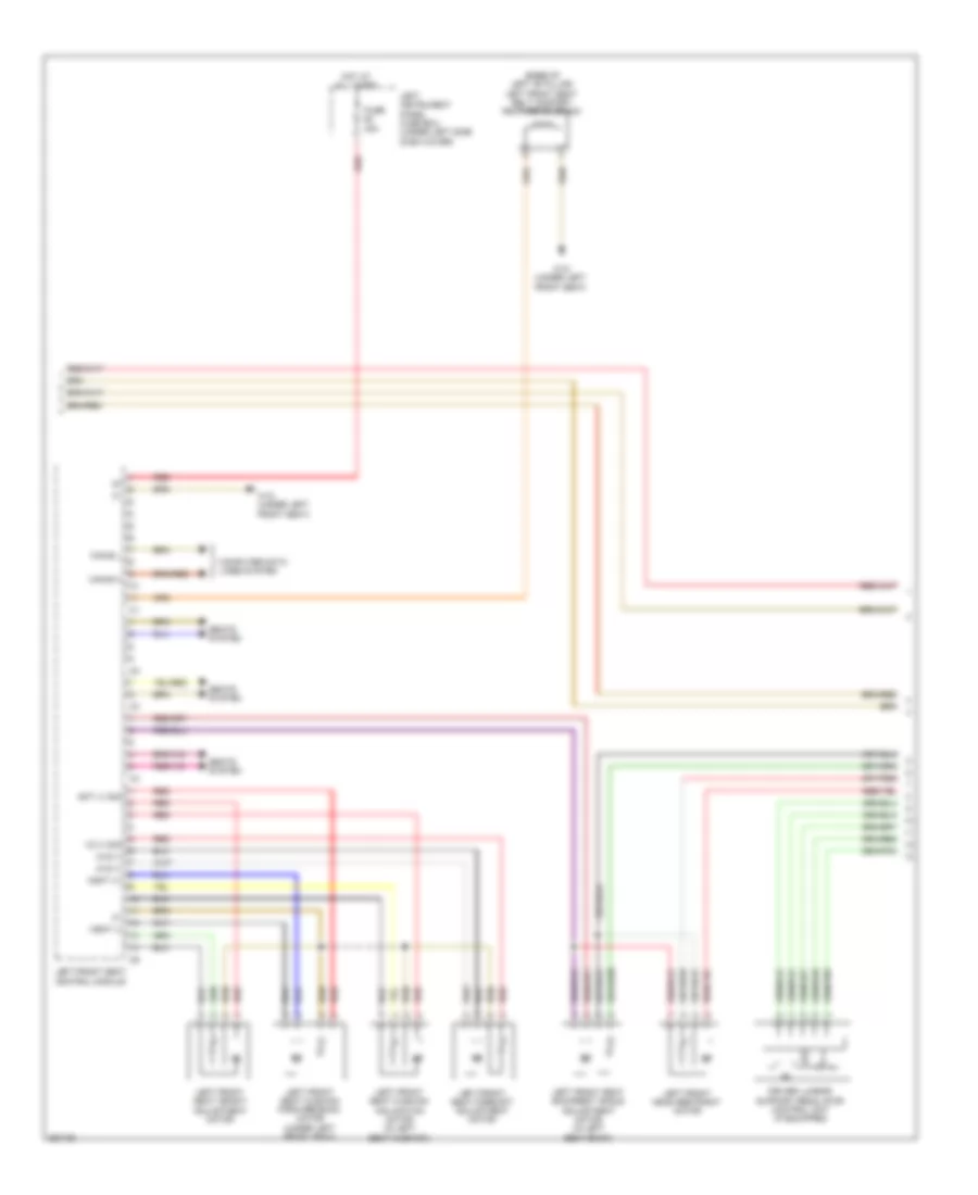
Active Body Control Wiring Diagram (1 of 2) for Mercedes-Benz S550 2011
List of elements for Active Body Control Wiring Diagram (1 of 2) for Mercedes-Benz S550 2011:
- Abc control module (left rear of engine compt)
- Abc front axle valve unit (left side of engine compt)
- Abc pressure sensor (under right front of vehicle)
- Abvls
- Abvrm
- Abvrv
- Front sam control module w/ fuse & relay module (left rear engine compt)
- Fuse 15a
- Hot at all times
- Left front abc pressure sensor (behind left front side of front bumper)
- Left front body acceleration sensor (left side of engine compt)
- Left front level sensor (left front wheelwell)
- Left front suspension strut plunger check valve
- Left front suspension strut plunger valve
- Nvlm
- Nvls
- Nvlv
- Nvrm
- Nvrs
- Pfbhlm
- Pfbhls
- Pfbhlv
- Pfbvlm
- Pfbvls
- Red
- Right front body acceleration sensor (right side of engine compt)
- Right front level sensor (right front wheelwell)
- Right front suspension strut plunger check valve
- Right front suspension strut plunger valve
- Sdvs
- Sdvv
- Sensor
- Sig
- Vaa l
- Vaa r
- Vav l
- Vav r
- Vvav l
- W15/1 (right front footwell)
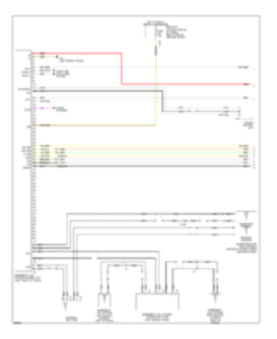
Active Body Control Wiring Diagram (2 of 2) for Mercedes-Benz S550 2011
List of elements for Active Body Control Wiring Diagram (2 of 2) for Mercedes-Benz S550 2011:
- (in left rear wheelwell) right rear level sensor
- (in right rear wheelwell) left rear level sensor
- Abc control module (left rear of engine compt)
- Abc lateral acceleration sensor (under front of center console)
- Abc rear axle valve unit (under center rear of vehicle)
- Abc suction restrictor valve (left front of engine compt)
- Abhrm
- Abhrs
- Abhrv
- Can
- Can-e h
- Can-e l
- Computer data lines system
- Haa l
- Haa r
- Hav l
- Hav r
- Left rear abc pressure sensor (in left rear wheelwell)
- Left rear suspension strut plunger check valve
- Left rear suspension strut plunger valve
- Nhlm
- Nhls
- Nhlv
- Nhrm
- Nhrs
- Nhrv
- Pfbhlm
- Pfbhls
- Pfbhlv
- Pfbhrm
- Pfbhrs
- Pfbhrv
- Pnk
- Qbmm
- Qbms
- Qbmv
- Red
- Right front abc pressure sensor (behind right front side of front bumper)
- Right rear abc pressure sensor (in right rear wheelwell)
- Right rear body acceleration sensor (right side of trunk)
- Right rear suspension strut plunger check valve
- Right rear suspension strut plunger valve
- Sig
Airmatic Control Wiring Diagram (1 of 2) for Mercedes-Benz S550 2011
List of elements for Airmatic Control Wiring Diagram (1 of 2) for Mercedes-Benz S550 2011:
- (+)
- (right side of engine compt) w2
- Air suspension compressor relay
- Airmatic compressor unit
- Airmatic w/ ads control module (left rear of engine compt)
- All times
- Can-b h
- Can-b l
- Computer data lines system
- Engine compartment prefuse box (right rear engine compt)
- Front sam control module w/ fuse & relay module (left rear engine compt)
- Fuse 150a
- Fuse 25a
- Fuse 46 15a
- Fuse 56 40a
- Gnd
- Hot at
- Hot at all times
- Left front axle damping valve unit (left front wheel house)
- Left front body acceleration sensor (left side of engine compt)
- Left front level sensor (left front wheelwell)
- Mr1
- Mr2
- Mr4
- Nca
- Nvlm
- Nvls 1
- Nvlv
- Nvrm
- Nvrs 1
- Nvrv
- Red
- Right front axle damping valve unit (right front wheel house)
- Right front body acceleration sensor (right side of engine compt)
- Right front level sensor (right front wheelwell)
- Sig
- Val 1
- Val 2
- Valv+
- Var 1
- Var 2
- Varv+
- Vkps
- Vkpv
- W15/1 (right front footwell)
- X62/6
- X62/7
- Zamvl
- Zasvl
- Zavvl
Airmatic Control Wiring Diagram (2 of 2) for Mercedes-Benz S550 2011
List of elements for Airmatic Control Wiring Diagram (2 of 2) for Mercedes-Benz S550 2011:
- (not used)
- (under right front of vehicle) level control valve unit
- Airmatic pressure sensor
- Airmatic w/ ads control module (left rear of engine compt)
- Can-e h
- Can-e l
- Central reservoir charge valve
- Computer data lines system
- Hal 1
- Hal 2
- Hal v
- Har 1
- Har 2
- Har v
- Left front
- Left rear
- Left rear axle damping valve unit (left rear wheel house)
- Leveling control valves
- Nca
- Nhrm
- Nhrs 1
- Nhrv
- Rear axle level sensor (under rear center of vehicle)
- Right front
- Right rear
- Right rear axle damping valve unit (right rear wheel house)
- X222
- X62/32-c
- X62/33-c
EMERGENCY VEHICLE SYSTEMS
Fire Suppression Wiring Diagram for Mercedes-Benz S550 2011
List of elements for Fire Suppression Wiring Diagram for Mercedes-Benz S550 2011:
- (right rear of engine compt) fresh air sensor
- Air conditioning system
- Authorities peripherals separation point
- Engine fire extinguishing system temperature sensor (left rear of engine compt)
- Extinguishing agent reservoir pressure monitoring switch 1
- Extinguishing agent reservoir pressure monitoring switch 2
- Extinguishing agent reservoir squib 1
- Extinguishing agent reservoir squib 2
- Fire extinguishing
- Fire extinguishing system control module
- Fire extinguishing system diagnostic interface
- Fire extinguishing system warning buzzer
- Fresh air system emergency control unit
- Fresh air system/fire extinguishing system emergency activate button
- Fresh air system/fire extinguishing system emergency activate button balance resistor
- Fuse 5a
- Hot at all times
- Nca
- Pas (gas) & special signal system control module (left front of trunk)
- Rear fire extinguishing system temperature sensor (under left rear of vehicle)
- Rear fuse box i
- Red
- Solenoid valve
- Special vehicle multi-function control module (svmcm (mss))
- System switch
- W/ medium reservoir solenoid valve
- W/o medium reservoir
- W7/1 (left rear footwell)
- X15/11
- X203
- X203/1
- X203/2
ENGINE PERFORMANCE
5.5L
5.5L, Engine Performance Wiring Diagram (1 of 5) for Mercedes-Benz S550 2011
List of elements for 5.5L, Engine Performance Wiring Diagram (1 of 5) for Mercedes-Benz S550 2011:
- (front of left cylinder bank) left exhaust camshaft hall sensor
- (front of left cylinder bank) left intake camshaft hall sensor
- Check engine mil indicator
- Circuit relay
- Computer data lines system
- Crankshaft hall sensor (left rear of engine)
- Engine compartment prefuse box (right rear engine compt)
- Ev 1
- Ev 2
- Ev 3
- Ev 5
- Ev 8
- Front sam control module w/ fuse & relay module (left rear engine compt)
- Fuse 150a mr1
- Fuse 7.5a
- Hot at all times
- Hot film maf sensor (center rear of engine)
- Instrument cluster
- Left intake manifold tumble flap position sensor
- Left knock sensor 2 (under intake manifold)
- Left o2 sensor upstream twc (kat) (left rear of engine compt)
- Me-sfi (me) control unit (right rear of engine compt)
- Mr4
- Nca
- Pressure sensor
- Red
- Right intake manifold tumble flap position sensor
- Right knock sensor 1 (right side of engine)
- Sig
- Throttle valve actuator (on throttle body assembly)
- X205
5.5L, Engine Performance Wiring Diagram (2 of 5) for Mercedes-Benz S550 2011
List of elements for 5.5L, Engine Performance Wiring Diagram (2 of 5) for Mercedes-Benz S550 2011:
- (not used)
- Ev 4
- Ev 6
- Ev 7
- Front of engine)
- Intake manifold tumble flap switchover valve
- Left o2 sensor downstream twc (kat) (under left front of vehicle)
- Me-sfi (me) control unit (right rear of engine compt)
- Nca
- O s kw out
- Oil level switch
- Red
- Right o2 sensor downstream twc (kat) (under right front of vehicle)
- Starting/ charging system
- Variable intake manifold switchover valve
- X205
- X26-c1
5.5L, Engine Performance Wiring Diagram (3 of 5) for Mercedes-Benz S550 2011
List of elements for 5.5L, Engine Performance Wiring Diagram (3 of 5) for Mercedes-Benz S550 2011:
- (front of left cylinder bank) left exhaust camshaft solenoid
- (front of right cylinder bank) right exhaust camshaft solenoid
- (front of right cylinder bank) right intake camshaft solenoid
- (injectors 1, 2, 3 & 4: top of right cylinder bank) (njectors 5, 6, 7 & 8: top of left cylinder bank) fuel injectors
- (left rear of engine)
- (right rear of engine)
- (top right side of engine) radio interference suppression capacitor 1
- Cylinder ignition coil 1 (top of right cylinder bank)
- Cylinder ignition coil 2 (top of right cylinder bank)
- Cylinder ignition coil 3 (top of right cylinder bank)
- Cylinder ignition coil 4 (top of right cylinder bank)
- Cylinder ignition coil 5 (top of left cylinder bank)
- Cylinder ignition coil 6 (top of left cylinder bank)
- Cylinder ignition coil 7 (top of left cylinder bank)
- Cylinder ignition coil 8 (top of left cylinder bank)
- Left intake camshaft solenoid (front of left cylinder
- Nca
- Radio interference suppression capacitor 2 (top left side of engine)
- Red
- Spark plug
- W11w1
- W11w1 (right rear of engine)
- W11w2
- W11w2 (left rear of engine)
5.5L, Engine Performance Wiring Diagram (4 of 5) for Mercedes-Benz S550 2011
List of elements for 5.5L, Engine Performance Wiring Diagram (4 of 5) for Mercedes-Benz S550 2011:
- (front of engine) coolant temperature sensor
- (front of right cylinder bank) right exhaust camshaft hall sensor
- (in fuel tank) left fuel level sensor
- (in fuel tank) right fuel level sensor
- (right rear of engine) heating system shutoff valve
- (top front of engine) air pump switchover valve
- Accelerator pedal sensor (top of accelerator pedal assembly)
- Fuel tank pressure sensor (in fuel tank)
- Fuse 25a
- Hot at all times
- Nca
- Power steering pump pressure regulator valve
- Rear sam control module w/ fuse & relay module (center trunk)
- Red
- Right intake camshaft hall sensor (front of right cylinder bank)
- Right o2 sensor upstream twc (kat) (right rear of engine compt)
- Sig
- Three-disk thermostat valve
5.5L, Engine Performance Wiring Diagram (5 of 5) for Mercedes-Benz S550 2011
List of elements for 5.5L, Engine Performance Wiring Diagram (5 of 5) for Mercedes-Benz S550 2011:
- (-)
- (left front footwell)
- +5v
- 87 me1
- Aav
- Activated charcoal canister shutoff valve (under right rear of vehicle)
- Air
- Air pump (center front of engine)
- Air pump relay
- Can-c h
- Can-c l
- Can-e h
- Can-e l
- Computer data lines system
- Crash
- Ds sig
- Ds+
- Ds-
- Egs
- Ekp
- Ekp+
- Ekp-
- Ekp-lauf
- Electric suction fan engine & ac w/ integrated control (behind center of radiator)
- Engine circuit 87 relay
- Front sam control module w/ fuse & relay module (left rear engine compt)
- Fuel pressure sensor (under left rear of vehicle)
- Fuel pump (fp)
- Fuel pump control module (under left rear seat)
- Fuse 10a
- Fuse 15a
- Fuse 20a
- Fuse 25a
- Fuse 60a
- Hot at all times
- Me-sfi (me) control unit (right rear of engine compt)
- Nca
- Purge control valve (left front of engine compt)
- Pwg+
- Pwg1-0
- Pwg1-1
- Pwg2-0
- Pwg2-1
- Red
- Sig
- Start
- Starter circuit 50 relay
- W11 (right front of engine)
- W17/1 (left rear footwell)
- W34/1
- X26-c1
- X26-c2
EXTERIOR LIGHTS
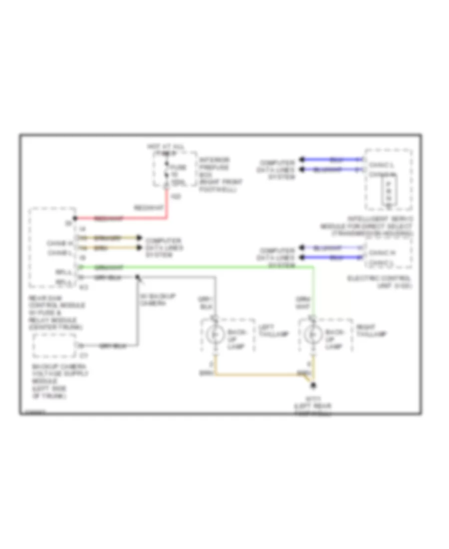
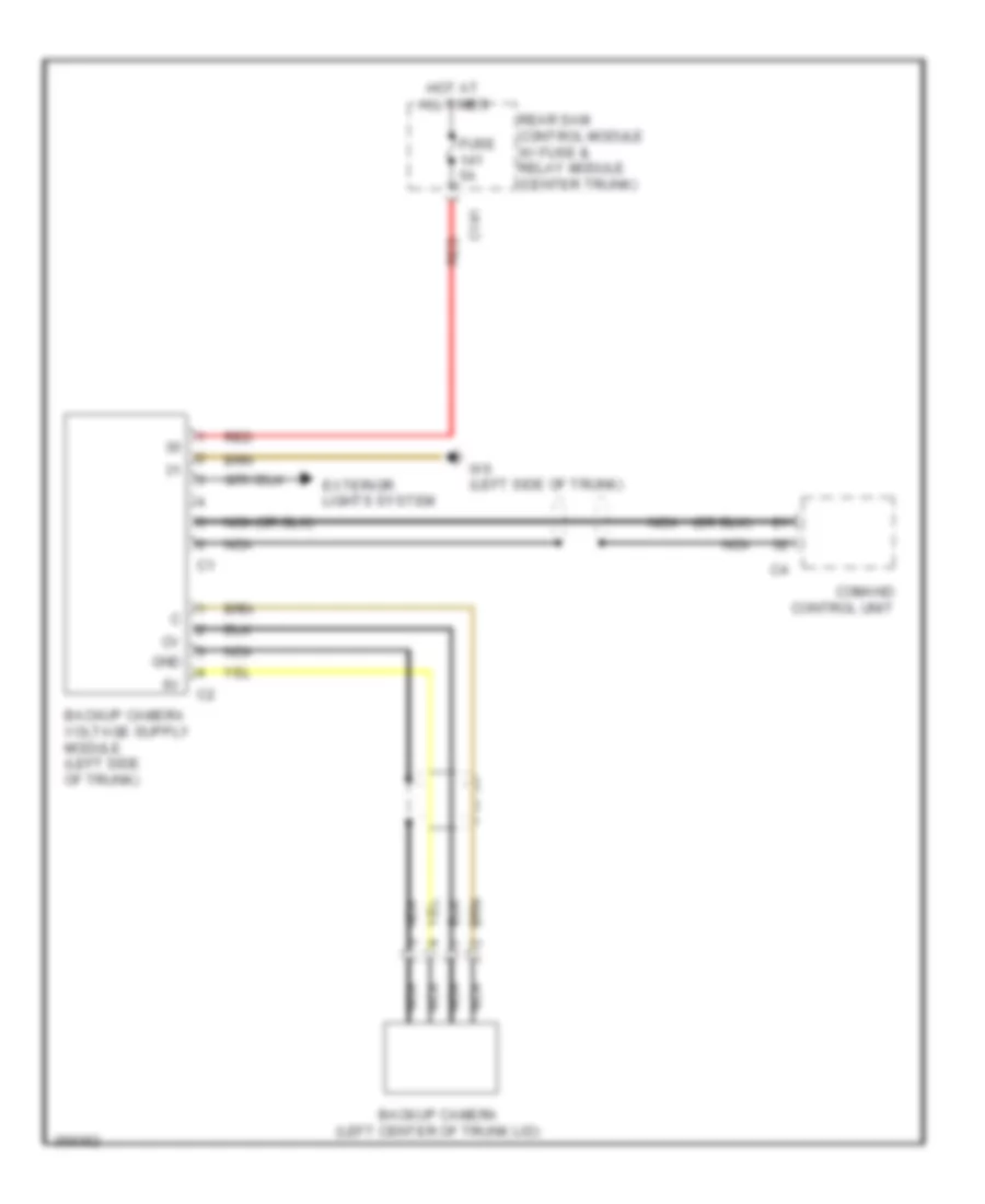
Backup Lamps Wiring Diagram for Mercedes-Benz S550 2011
List of elements for Backup Lamps Wiring Diagram for Mercedes-Benz S550 2011:
- Back- up lamp
- Can-b h
- Can-b l
- Can-c h
- Can-c l
- Computer data lines system
- Electric control unit (vgs)
- Fuse 150a
- Hot at all times
- Ig3
- Intelligent servo module for direct select (transmission housing)
- Interior prefuse box (right front footwell)
- Left taillamp
- P r n d
- Rear sam control module w/ fuse & relay module (center trunk)
- Rfl-l
- Right taillamp
- W/ backup camera
- W7/1 (left rear footwell)
Exterior Lamps Wiring Diagram (1 of 2) for Mercedes-Benz S550 2011
List of elements for Exterior Lamps Wiring Diagram (1 of 2) for Mercedes-Benz S550 2011:
- (if equipped) cornering illumination
- (w/ cornering illumination) left dynamic cornering lamp motor
- (w/ cornering illumination) right dynamic cornering lamp motor
- 3.bl
- 49a l
- 49a r
- 57 l
- 57 r
- Backup lamp
- Backup lamps circuit
- Bi-l
- Bi-r
- Bsl-l
- Bsl-r
- Can-b h
- Can-b l
- Can-e h
- Can-e l
- Center high mounted stop lamp
- Computer data lines system
- Engine compartment prefuse box (right rear engine compt)
- Front sam control module w/ fuse & relay module (left rear engine compt)
- Fuse 150a
- Hot at all times
- I10
- Kzl-l
- Kzl-r
- Left active curve illumination position sensor
- Left front headlamp unit
- Left front side marker lamp
- Left license plate lamp
- Left taillamp
- Mr1
- Mr4
- Mr5
- Mr6
- Mr9
- Nca
- Nsl-l
- Nsl-r
- Rear fog lamp
- Rear sam control module w/ fuse & relay module (center trunk)
- Rear side marker lamp
- Red
- Rfl-l
- Right active curve illumination position sensor
- Right front headlamp unit
- Right front side marker lamp
- Right license plate lamp
- Right taillamp
- Standing & parking lamp
- Stop, tail & parking lamp
- Turn signal lamp
- W/ backup camera
- W15/1 (right front footwell)
- W17/1 (left rear footwell)
- W3/1 (right side of engine compt)
- W3/2 (left side of engine compt)
- W54 (right front trunk)
- W7/1 (left rear footwell)
- Xenon headlamp control module
Exterior Lamps Wiring Diagram (2 of 2) for Mercedes-Benz S550 2011
List of elements for Exterior Lamps Wiring Diagram (2 of 2) for Mercedes-Benz S550 2011:
- Analog clock
- Audible
- Can-b h
- Can-b l
- Can-b-h
- Can-b-l
- Can-e h
- Can-e l
- Can-f h
- Can-f l
- Cockpit switch group
- Combination switch
- Computer data lines system
- Fog lamp indicator
- Front central operating unit
- Fuse 150a
- Hazard warning system button
- Hcs (sra) switch
- Headlamp flasher/ high beam switch
- Hot at all times
- Instrument cluster
- Interior prefuse box (right front footwell)
- Left & right turn signal switch
- Left electrically adjustable & heated outside mirror
- Left front door control module (in left front door)
- Left turn signal ind
- Night vision assist button
- Outside mirror ambient lamp
- Outside mirror turn signal lamp
- Rear fog lamp indicator
- Red
- Right electrically adjustable & heated outside mirror
- Right front door control module (in right front door)
- Right turn signal ind
- Rotary light switch
- Steering column module (top of steering column)
- Turn signal indicator
- Upper control panel control module
- X18-c1
GROUND DISTRIBUTION
Ground Distribution Wiring Diagram (1 of 2) for Mercedes-Benz S550 2011
List of elements for Ground Distribution Wiring Diagram (1 of 2) for Mercedes-Benz S550 2011:
- & starter battery
- Air bag system driver assist, driver side frontal acceleration sensor, restraint systems control module & wss control unit (weight sensing system)
- Battery sensor
- Electric air pump, radio interference suppression capacitor 1, cylinder 1 ignition coil, cylinder 2 ignition coil, cylinder 3 ignition coil & cylinder 4 ignition coil
- Engine & ac electric suction fan w/ integrated control, airmatic compressor unit (if equipped) & electrohydraulic power steering
- Esp control module & regenerative braking system control unit
- High voltage battery
- Hybrid can voltage distributor connector, nox sensor control unit downstream of scr catalytic converter, me-sfi (me) control module, alarm signal siren, left front door control module & cylinder ignition coils 1,2,3,4,5,6,7 & 8
- Left front side marker lamp (usa), right front side marker lamp (usa), ata (edw) hood switch, airmatic w/ads control unit, abc control module, intelligent servo module for direct select, electric control unit (vgs), etc (egs) control module, right front door control module, front cigar lighter (w/ ashtray illumination), chassis can/ffs (rba) voltage distributor connector, telematics can voltage distributor connector dc/dc converter control module, radiator sensor for engine diagnosis, hybrid engine hood contact switch, power electronics circulation pump 1, power electronics circulation pump 2, electric transmission oil pump, electric refrigerant compressor, battery management system control unit, eco start/stop function diode (if equipped), high-volt battery cooling system shutoff valve & left engine hood contact switch (w/ eco start/stop function)
- Radio interference suppression capacitor 2, cylinder 5 ignition coil, cylinder 6 ignition coil, cylinder 7 ignition coil & cylinder 8 ignition coil
- Rear head restraints valve block, right rear brake pad contact sensor, panoramic sliding roof control module, panoramic sliding sunroof circuit 31 connector sleeve, eco start/stop function relay (if equipped), rear cigar lighter, right rear seat belt buckle switch, left rear seat belt buckle switch, rear center air outlet potentiometer & stowage compartment illumination
- Splitview display (if equipped), instrument cluster, comand display, comand control unit, night vision assist control unit (if equipped), front central operating unit & multifunction camera
- W10 (right rear of engine compt)
- W10/4 (right side of tank)
- W11w1 (right rear of engine)
- W11w2 (left rear of engine)
- W14/3 (right front engine compt)
- W15/1 (right front footwell)
- W17 (right rear footwell)
- W18 (under left front seat)
- W2 (right side of engine compt)
- W26 (under front of center console)
- W26/1
- W3/1 (right side of engine compt)
- W34/1 (left front footwell)
- W43 (left front footwell)
- W45
- W7/1 (left rear footwell)
- Wiper park heater, right fanfare horn, right front headlamp unit, right fog lamp, dtr control unit (w/ bi-xenon), front prefuse & right daytime running lamp's headlamps (if equipped)
- X28/29
Ground Distribution Wiring Diagram (2 of 2) for Mercedes-Benz S550 2011
List of elements for Ground Distribution Wiring Diagram (2 of 2) for Mercedes-Benz S550 2011:
- Ac recirculation unit & ptc heater booster (if equipped)
- Coolant circulation pump, left fanfare horn, slave wiper motor, master wiper motor, washer nozzle hose heater, hcs pump & windshield washer fluid pump, right front lamp unit, right fog lamp (w/ bi-xenon) & right-daytime running lamps headlamp (if equipped)
- Dc/dc converter control module
- Electric air pump & power electronics control unit
- Power electronics control unit
- Rear bumper left outer radar sensor, inner left rear pts ultrasonic sensor, rear sam control module w/ fuse & relay module, rear bumper right inner radar sensor, rear pts warning indicator, rear bumper left inner radar sensor, pts control module, outer left front pts ultrasonic sensor, outer right front pts ultrasonic sensor, center right front pts ultrasonic sensor, center left front pts ultrasonic sensor, inner left front pts ultrasonic sensor, inner right front pts ultrasonic sensor, front bumper left outer radar sensor, front bumper left inner radar sensor, front bumper right inner radar sensor, front bumper right outer radar sensor, outer right rear pts ultrasonic sensor, inner right rear pts ultrasonic sensor, outer left rear pts ultrasonic sensor, rcp (hbf) control unit, left rear multicontour backrest control unit, right rear multicontour backrest control unit, lumbar pump (if equipped), multi contour seat pneumatic pump (if equipped) & center high-mounted stop lamp
- Rear sam control module w/ fuse & relay module, electric parking brake control unit tpm (rdk) control unit & keyless go control unit
- Steering column module, central gateway control module, eis (ezs) control unit, glove compartment lamp, right front footwell lamp, left front footwell lamp, electric parking brake switch, left side air outlet potentiometer, front sam control module w/ fuse & relay module, upper control panel control module, instrument cluster, right side air outlet potentiometer, front center air outlet potentiometer, data link connector, aac (kla) control unit, additional battery & 12 volt connector in glove compartment
- Vacuum pump relay (-)
- W11 (right front of engine)
- W15 (right front footwell)
- W17/1 (left rear footwell)
- W19 (under right front seat)
- W20
- W26/2
- W3/2 (left side of engine compt)
- W3/9
- W34 (left front footwell)
- W50
- W54 (right front trunk)
- W54/3 (left front trunk)
- W6 (left side of trunk)
- X28/30
HEADLIGHTS
Headlights Wiring Diagram for Mercedes-Benz S550 2011
List of elements for Headlights Wiring Diagram for Mercedes-Benz S550 2011:
- (right side of engine compt) w3/1
- 55 r
- 55l
- 56al
- 56ar
- 56d
- Adjustment
- Bi-xenon
- Bi-xenon lamp w/ integral ignition module
- Can b h
- Can b l
- Can-b h
- Can-b l
- Can-e h
- Can-e l
- Can-f h
- Can-f l
- Can-g h
- Can-g l
- Cluster
- Combination switch
- Computer
- Computer data lines system
- Data lines
- Engine compartment prefuse box (right rear engine compt)
- Fog lamp indicator
- Front sam control module w/ fuse & relay module (left rear engine compt)
- Fuse 10a
- Fuse 150a
- Headlamp flasher/ high beam switch
- Headlamp range
- Headlamp range adjustment motor
- High beam
- High beam indicator lamp
- High beam solenoid
- Hot at all times
- Hot w/ circuit 15 relay energized
- Ignition module
- Infrared lamp
- Instrument
- Instrument cluster system
- Lamp w/ integral
- Left daytime running lamps headlamp (if equipped)
- Left front fog lamp
- Left front headlamp unit
- Left taillamp
- Low beam lamp
- Low beam switch
- Motor
- Mr1
- Mr2
- Mr4
- Mr5
- Mr6
- Nsl-l
- Nsl-r
- Rear fog lamp
- Rear fog lamp ind
- Rear sam control module w/ fuse & relay module (center trunk)
- Red
- Right daytime running lamps headlamp (if equipped)
- Right front fog lamp
- Right front headlamp unit
- Right taillamp
- Rotary light switch
- Solenoid
- Steering column module (top of steering column)
- System
- Upper control panel control module
- W/ night vision assist
- W3/1 (right side of engine compt)
- W3/2 (left side of engine compt)
- W34 (left front footwell)
- W7/1 (left rear footwell)
- X219
- Xenon headlamp control module (part of left headlamp unit)
- Xenon headlamp control module (part of right headlamp unit)
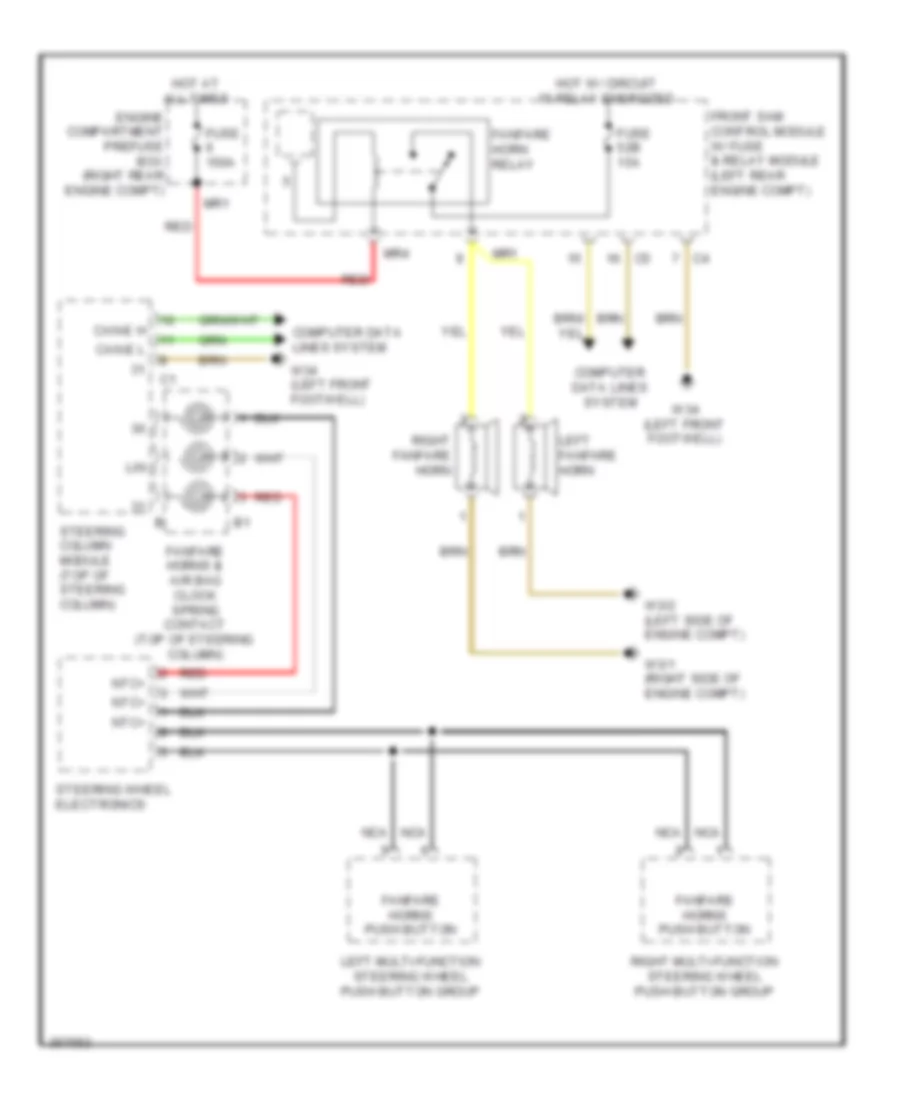
HORN
Horn Wiring Diagram for Mercedes-Benz S550 2011
List of elements for Horn Wiring Diagram for Mercedes-Benz S550 2011:
- Can-e h
- Can-e l
- Computer data lines system
- Engine compartment prefuse box (right rear engine compt)
- Fanfare horn relay
- Fanfare horns & air bag clock spring contact (top of steering column)
- Fanfare horns push button
- Front sam control module w/ fuse & relay module (left rear engine compt)
- Fuse 150a
- Fuse 52b 15a
- Hot at all times
- Hot w/ circuit 15 relay energized
- Left fanfare horn
- Left multi-function steering wheel push button group
- Lin
- Mr1
- Mr4
- Nca
- Ntc+
- Red
- Right fanfare horn
- Right multi-function steering wheel push button group
- Steering column module (top of steering column)
- Steering wheel electronics
- W3/1 (right side of engine compt)
- W3/2 (left side of engine compt)
- W34 (left front footwell)
INSTRUMENT CLUSTER
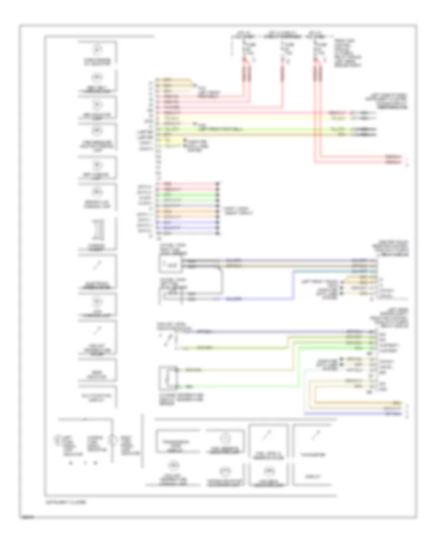
Instrument Cluster Wiring Diagram (1 of 2) for Mercedes-Benz S550 2011
List of elements for Instrument Cluster Wiring Diagram (1 of 2) for Mercedes-Benz S550 2011:
- (center trunk) rear sam control module w/ fuse & relay module
- (in fuel tank) left fuel level sensor
- (in fuel tank) right fuel level sensor
- (left front trunk) w54/3 computer data lines system
- (left rear engine compt) front sam control module w/ fuse & relay module
- (left side of dash) instrument cluster/ comand display additional fan
- 15g
- 58d
- Abs indicator lamp
- Air bag indicator & warning lamp
- Audible turn signal indicator
- Austemp +
- Austemp -
- Brake fluid warning lamp
- Can b h
- Can b l
- Can-f h
- Can-f l
- Check engine mil indicator
- Clock +
- Clock -
- Computer data lines system
- Coolant level indicator switch
- Coolant temperature gauge
- Coolant temperature warning lamp
- Data 0 +
- Data 0 -
- Data 1 +
- Data 1 -
- Data 2 +
- Data 2 -
- Diag
- Display
- Dtr warning lamp
- Electronic speedometer
- Esp warning lamp
- Front sam control module w/ fuse & relay module (left rear engine compt)
- Fuel level & reserve gauge
- Fuel reserve indicator lamp
- Fuse 7.5a
- Gear indicator
- Gnd
- High beam indicator lamp
- Hot at all times
- Hot w/ circuit 15 relay energized
- Instrument cluster
- Left turn signal lamp indicator
- Luefter
- Mr7
- Multi-function display
- Nca
- Night vision assist circuit
- Outside temperature display temperature sensor
- Pnk/red
- Red
- Right turn signal lamp indicator
- Seat belt warning lamp
- Sig
- Tachometer
- Tire pressure monitor warning lamp
- Transmission mode display
- W34 (left front footwell)
- W43 (left front footwell)
- Warning buzzer
Instrument Cluster Wiring Diagram (2 of 2) for Mercedes-Benz S550 2011
List of elements for Instrument Cluster Wiring Diagram (2 of 2) for Mercedes-Benz S550 2011:
- (left front footwell) w34
- 58d
- Air recirculation button
- Analog clock
- Ata(edw) function indicator
- Automatic child seat recognition airbag off ind lamp
- Brake fluid indicator switch (left rear of engine compt)
- Can g h
- Can g l
- Can-b h
- Can-b l
- Cockpit switch group
- Comand display brightness control
- Computer data lines system
- Cruise control system
- Defrost/ heated windshield button
- Electric parking brake control unit (left rear wheelwell)
- Electric parking brake switch
- Esp off switch
- Frb vl
- Frb vr
- Heated rear window button
- Hsk bel
- Interior lights system
- Interior lights system computer data lines system
- Left automatic air conditioning button
- Left blower button
- Left comand display swivel switch
- Left temperature selection button
- Level adjustment switch
- Night view assist display brightness control switch & controls illumination
- Night vision assist button
- Off/ residual heat button
- Overhead control panel circuit
- Pts off switch
- Right automatic air conditioning button
- Right blower button
- Right comand display swivel switch
- Right temperature selection button
- Rotary light switch
- Sig
- Sth/zuh/ residual heat button
- Sw 1
- Sw 3
- Sw 4
- Sw 6
- Upper control panel control unit
- W34 (left front footwell)
- X18-c2
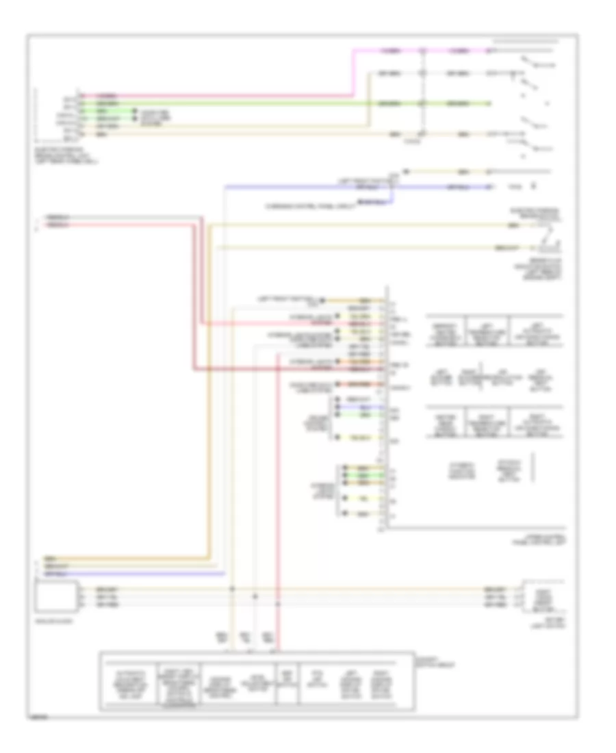
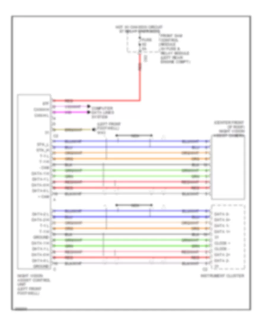
Night Vision Wiring Diagram for Mercedes-Benz S550 2011
List of elements for Night Vision Wiring Diagram for Mercedes-Benz S550 2011:
- (center front of roof) night vision assist camera
- (left front footwell) w43
- + cam
- - cam
- 87f
- C62
- Can-h h
- Can-h l
- Clock +
- Clock -
- Computer data lines system
- Data 0+
- Data 0-
- Data 1+
- Data 1-
- Data 2+
- Data 2-
- Data-0 h
- Data-0 l
- Data-1 h
- Data-1 l
- Data-2 h
- Data-2 l
- Front sam control module w/ fuse & relay module (left rear engine compt)
- Fuse 5a
- Ground
- Hot w/ chassis circuit 87 relay energized
- Instrument cluster
- Nca
- Night vision assist control unit (left front footwell)
- Red
- Stk_h
- Stk_l
- T-1 h
- T-1 l
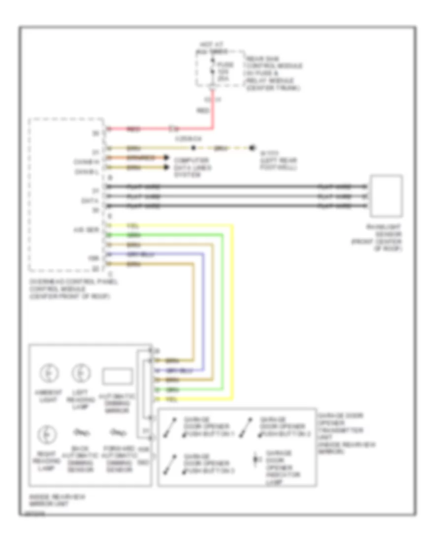
Overhead Console Wiring Diagram for Mercedes-Benz S550 2011
List of elements for Overhead Console Wiring Diagram for Mercedes-Benz S550 2011:
- (front center of roof) rain/light sensor
- (left rear footwell) w17/1
- 15r
- 30g
- 58d
- Als ser
- Ambient lamp
- Automatic dimming mirror
- Back automatic dimming interior rearview mirror sensor
- Can b h
- Can b l
- Computer data lines system
- Data
- Door contact on/off switch
- Electric parking brake switch
- Emergency call system control unit (left front of trunk)
- Flat wire
- Forward automatic dimming interior rearview mirror sensor
- Front dome lamp
- Front dome lamp switch
- Front sam control module w/ fuse & relay module (left rear engine compt)
- Fuse 25a
- Garage door opener button 1
- Garage door opener button 2
- Garage door opener button 3
- Garage door opener indicator lamp
- Garage door opener transmitter unit (inside rearview mirror)
- Hot at all times
- Inside rearview mirror unit
- Interior lights system
- Left front reading lamp switch
- Left reading lamp
- Ll hl
- Ll hr
- Mb info & telediagnosis button group
- Nca
- Overhead control panel control module (center front of roof)
- Rear dome lamp switch
- Rear roller sun blind switch
- Rear sam control module w/ fuse & relay module (center trunk)
- Red
- Right front reading lamp switch
- Right reading lamp
- Roof switch
- Sos pushbutton switch
- W6 (left side of trunk)
- X18-c1
- X25/8-c4
- X25/8-c5a
- X25/8-csa
- X39/48-c1
INTERIOR LIGHTS
Interior Lights Wiring Diagram (1 of 4) for Mercedes-Benz S550 2011
List of elements for Interior Lights Wiring Diagram (1 of 4) for Mercedes-Benz S550 2011:
- 15r
- 30g
- 58d
- Ais ser
- Ambiance illumination led 1
- Ambiance illumination led 2
- Ambiance illumination led 3
- Ambient lamp
- Can-b h
- Can-b l
- Computer data lines system
- Data
- Exterior lights system
- Flat wire
- Fog lamp ind lamp
- Frb-vl
- Frb-vr
- Fuse 150a i3
- Garage door opener assembly
- Garage door opener indicator lamp
- Glove compartment lamp
- Glove compartment lamp switch
- Hot at all times
- Hsk-bel
- Interior prefuse box (right front footwell)
- Interior rearview mirror unit
- Left front footwell lamp
- Left front vanity mirror illumination
- Left front vanity mirror illumination switch
- Left luggage compartment lamp
- Left reading lamp
- Left rear dome lamp
- Left rear vanity mirror illumination
- Left trunk lid ambient & warning lamp
- Ll hl
- Ll hr
- Nca
- Overhead control panel control module (center front of roof)
- Rain/light sensor (front center of roof)
- Rear ambient lamp
- Rear fog lamp ind lamp
- Rear sam control module w/ fuse & relay module (center trunk)
- Red
- Right front footwell lamp
- Right front vanity mirror illumination
- Right front vanity mirror illumination switch
- Right luggage compartment lamp
- Right reading lamp
- Right rear vanity mirror illumination
- Right trunk lid ambient & warning lamp
- Roof switch, dome contact on & off sw, rear dome lamp switch, left front reading lamp switch, front dome lamp & right front reading lamp switch
- Rotary light switch
- Upper control panel control module
- W17/1 (left rear footwell)
- W34 (left front footwell)
- W54 (right front trunk)
- X29/1
- X99/9-c1
- X99/9-c2
- X99/9-c3
Interior Lights Wiring Diagram (2 of 4) for Mercedes-Benz S550 2011
List of elements for Interior Lights Wiring Diagram (2 of 4) for Mercedes-Benz S550 2011:
- (-)
- 58d
- Can-b h
- Can-b l
- Computer data lines system
- Dfk
- Flat wire
- Red
- Right front door control module (in right front door)
- Right front door entrance/ exit lamp
- Right front door inside handle illumination
- Right front door lock switch
- Right front door trim strip illum- ination lamp 1
- Right front door trim strip illumination lamp 2
- Right front door warning lamp
- Right front drive lock pawl switch
- Right front rotary tumbler switch
- Right front safety limit switch
- Right front seat control module
- Right rear dome lamp
- Right rear footwell lamp
- W/ ambiance illumination
- W/ power closing
- W/o ambiance illumination
- W15/1 (right front footwell)
- X157/6-c1
- X157/6-c2
- X35/2-c5
Interior Lights Wiring Diagram (3 of 4) for Mercedes-Benz S550 2011
List of elements for Interior Lights Wiring Diagram (3 of 4) for Mercedes-Benz S550 2011:
- (-)
- (w/ ambiance illumination)
- (w/o ambiance illumination)
- 58d
- Can-b h
- Can-b l
- Computer data lines system
- Data
- Dfk
- Driver power window outside mirror & trunk lid switch group
- Flat wire
- Fuse 40a
- Hot at all times
- Left front door control module (in left front door)
- Left front door entrance/exit lamp
- Left front door inside handle illumination
- Left front door lock unit
- Left front door trim strip illumination lamp 1
- Left front door trim strip illumination lamp 2
- Left front door warning lamp
- Left front drive lock pawl switch
- Left front power closing motor
- Left front rotary tumbler switch
- Left front safety limit switch
- Left front seat control module
- Left rear footwell lamp
- Red
- Right instrument panel fuse box (under right side dash cover)
- Svs-mot
- Trunk lid open/close switch
- W/ power closing
- W34/1 (left front footwell)
- X157/7-c1
- X157/7-c2
Interior Lights Wiring Diagram (4 of 4) for Mercedes-Benz S550 2011
List of elements for Interior Lights Wiring Diagram (4 of 4) for Mercedes-Benz S550 2011:
- (-)
- (under left front seat) w18
- 58d
- Can-b h
- Can-b l
- Computer data lines system
- Cornering illumination (if equipped)
- Dfk
- Flat wire
- Front cigar lighter (w/ ashtray illumination)
- Front sam control module w/ fuse & relay module (left rear engine compt)
- Ground distribution system
- Left front headlamp unit
- Left rear ashtray illumination (w/ ambiance illumination)
- Left rear door control module
- Left rear door entrance/ exit lamp
- Left rear door inside handle illumination
- Left rear door lock unit
- Left rear door trim strip illumination
- Left rear door warning lamp
- Left rear drive lock pawl switch
- Left rear rotary tumbler switch
- Left rear safety limit switch
- Left xenon headlamp control module
- Mr5
- Mr6
- Nca
- Rear cigar lighter
- Red
- Right front headlamp unit
- Right rear ashtray illumination (w/ ambiance illumination)
- Right rear door control module (in right rear door)
- Right rear door entrance/exit lamp
- Right rear door inside handle illumination
- Right rear door lock unit
- Right rear door trim strip illumination
- Right rear door warning lamp
- Right rear drive lock pawl switch
- Right rear rotary tumbler switch
- Right rear safety limit switch
- Right xenon headlamp control module
- Spiegel l
- Spiegel r
- Stowage compartment illumination
- W/ ambiance illumination
- W/ power closing
- W/o ambiance illumination
- W15/1 (right front footwell)
- W17 (right rear footwell)
- W19 (under right front seat)
- X35/3-c1
- X35/4-c1
MEMORY SYSTEMS
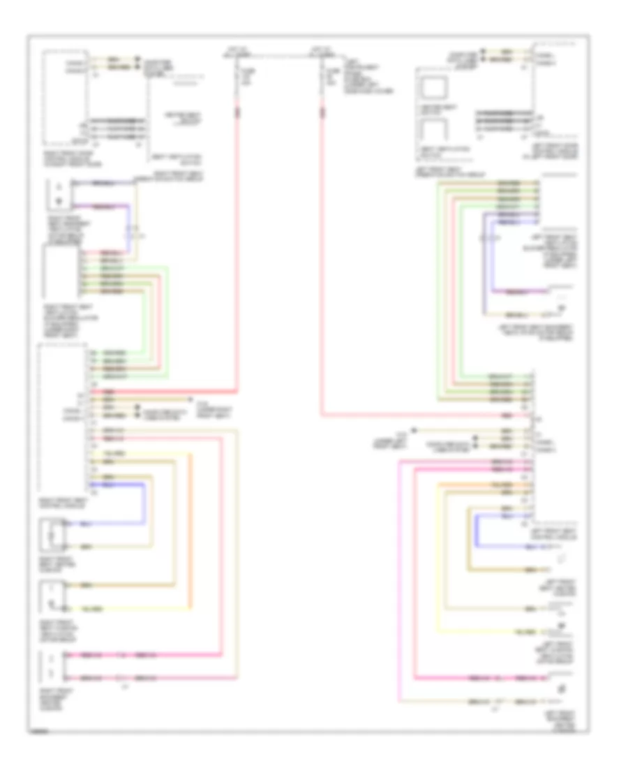
Driver"s Memory Seat Wiring Diagram (1 of 3) for Mercedes-Benz S550 2011
List of elements for Driver"s Memory Seat Wiring Diagram (1 of 3) for Mercedes-Benz S550 2011:
- Backrest switch
- Can-a h
- Can-a l
- Can-b h
- Can-b l
- Can-f h
- Can-f l
- Central gateway control module (left front upper footwell)
- Computer data lines system
- Data
- Dynamic driver seat massage function main valve
- Flat wire
- Fore/aft,hieght & inclination adjustment switch
- Front central operating unit
- Front sam control module w/ fuse & relay module (left rear engine compt)
- Head restraint adjustment switch
- Left front door control module (in left front door)
- Left front dynamic seat control module
- Left front seat massage function actuator motor
- Left front seat operation switch group
- Red
- Seat cushion fore/aft switch
Driver"s Memory Seat Wiring Diagram (2 of 3) for Mercedes-Benz S550 2011
List of elements for Driver"s Memory Seat Wiring Diagram (2 of 3) for Mercedes-Benz S550 2011:
- (base of left "b" pillar) left front seat belt comfort feature solenoid
- Can-b h
- Can-b l
- Computer data lines system
- Driver lumbar support regulator control unit (if equipped)
- Fuse 40a
- Hot at all times
- Left front head restraint motor
- Left front seat backrest angle adjustment motor (in left seat back)
- Left front seat control module
- Left front seat cushion forward/back motor (under left front seat)
- Left front seat cushion inclination motor (in left seat cushion)
- Left front seat fore/aft adjustment motor
- Left front seat height adjustment motor
- Left instrument panel fuse box (under left side dash cover)
- Mskt (+)
- Msnt (-)
- Mvz (-)
- Red
- Seats system
- Skt (+) sig
- Vz (+) sig
- W18 (under left front seat)
Driver"s Memory Seat Wiring Diagram (3 of 3) for Mercedes-Benz S550 2011
List of elements for Driver"s Memory Seat Wiring Diagram (3 of 3) for Mercedes-Benz S550 2011:
- (left rear footwell) w17/1
- 30g
- Can-a h
- Can-a l
- Can-b h
- Can-b l
- Comand control unit
- Comand display
- Computer data lines system
- Fuse 30a
- Hot at all times
- Left front seat control module
- Left rear footwell lamp
- Lumbar pump (left side of trunk)
- Nca
- Pneumatic pump for dynamic seat control (w/ dynamic seat) multicontour seat pneumatic pump (w/ multicontour seat) (w/ multi contour seat: left side of trunk) (w/ dynamic seat: left front of trunk)
- Rear sam control module w/ fuse & relay module (center trunk)
- Red
- Seats system
- Sp1m
- Sp1s
- Usr1
- W/ lumbar support seat
- W/ multicontour seat & dynamic seat
Memory Mirrors Wiring Diagram for Mercedes-Benz S550 2011
List of elements for Memory Mirrors Wiring Diagram for Mercedes-Benz S550 2011:
- (in left front door)
- (in right front door) right front door control module
- +5v
- Ambient lamp
- Automatic dimming mirror
- Bsm bereit
- Bsm warn
- Can-b h
- Can-b l
- Computer data lines system
- Data
- Driver power window outside mirror & trunk lid switch group
- Flat wire
- Fold-in/ fold-out switch
- Fuse 40a
- Hot at all times
- Left blind spot assistant indicator lamp (if equipped)
- Left blind spot readiness & warning indicator (if equipped)
- Left electrically adjustable & heated outside mirror
- Left front door control module
- Left front seat operation switch group
- Left outside mirror turn signal lamp
- Left/right outside mirror adjustment selection switch
- Memory 1, 2, 3 switch
- Memory switch
- Mirror adjustment rocker switch
- Mirror fold-in motor
- Mirror heater
- Mirror in/out adjust- ment
- Mirror up/down adjust- ment
- Motor
- Nca
- Red
- Right electrically adjustable & heated outside mirror
- Right instrument panel fuse box (under right side dash cover)
- Right outside mirror turn signal lamp
- W15/1 (right front footwell)
- W34/1 (left front footwell)
- X35/2-c5
Memory Rear Seat Wiring Diagram for Mercedes-Benz S550 2011
List of elements for Memory Rear Seat Wiring Diagram for Mercedes-Benz S550 2011:
- (+)
- (right front trunk) w54
- Backrest switch
- C143
- C144
- Can-b h
- Can-b l
- Computer data lines system
- Data
- Flat wire
- Fore/aft adjustment switch
- Front (or) rear seat adjustment selection switch
- Fuse 25a
- Head restraint adjustment switch
- Hot at all times
- Hs lv+
- Hs lv-
- Hs nv+
- Hs nv-
- Left rear door control module
- Left rear head restraint inclination adjustment motor
- Left rear seat belt comfort feature solenoid (under left rear window shelf)
- Left rear seat cushion inclination adjustment motor (under left rear seat)
- Left rear seat fore/aft adjustment motor (under left rear seat)
- Left rear seat operation switch group
- Mot-l
- Mot-lv
- Mot-nv
- Pnk/red
- Rear sam control module w/ fuse & relay module (center trunk)
- Rear seats control module (right side of trunk)
- Red
- Right rear door control module (in right rear door)
- Right rear head restraint inclination adjustment motor
- Right rear seat belt comfort feature solenoid
- Right rear seat cushion inclination adjustment motor (under right rear seat)
- Right rear seat operation switch group
- Right seat fore/aft adjustment motor (under right rear seat)
- Seat cushion inclination switch
- Seats system
- Sibl
- W54 (right front trunk)
Passenger"s Memory Seat Wiring Diagram (1 of 3) for Mercedes-Benz S550 2011
List of elements for Passenger"s Memory Seat Wiring Diagram (1 of 3) for Mercedes-Benz S550 2011:
- (left rear footwell) w17/1
- Can-a h
- Can-a l
- Can-b h
- Can-b l
- Can-f h
- Can-f l
- Central gateway control module (left front upper footwell)
- Comand control unit
- Comand display
- Computer data lines system
- Dynamic front passenger seat massage function main valve
- Front central operating unit
- Fuse 30a
- Hot at all times
- Lumbar pump (left side of trunk)
- Nca
- Pneumatic pump for dynamic seat control (w/ dynamic seat) multicontour seat pneumatic pump (w/ multicontour seat) (w/ multicontour seat: left side of trunk) (w/ dynamic seat: left front of trunk)
- Rear sam control module w/ fuse & relay module (center trunk)
- Red
- Right front dynamic seat control module
- Right front seat massage function actuator motor
- W/ lumbar support seat
- W/ multicontour seat & dynamic seat
Passenger"s Memory Seat Wiring Diagram (2 of 3) for Mercedes-Benz S550 2011
List of elements for Passenger"s Memory Seat Wiring Diagram (2 of 3) for Mercedes-Benz S550 2011:
- 30g
- Backrest switch
- Can-b h
- Can-b l
- Computer data lines system
- Data
- Flat wire
- Fore/aft, height & inclination adjustment switch
- Front sam control module w/ fuse & relay module (left rear engine compt)
- Head restraint adjustment switch
- Right front door control module (in right front door)
- Right front seat control module
- Right front seat operation switch group
- Right rear footwell lamp
- Seat cuhion fore/aft switch
- Seats system
Passenger"s Memory Seat Wiring Diagram (3 of 3) for Mercedes-Benz S550 2011
List of elements for Passenger"s Memory Seat Wiring Diagram (3 of 3) for Mercedes-Benz S550 2011:
- (if equipped) front passenger lumbar support regulator control unit
- Can-b h
- Can-b l
- Computer data lines system
- Fuse 40a
- Hot at all times
- Left instrument panel fuse box (under left side dash cover)
- Red
- Right front backrest angle adjustment motor
- Right front head restraint motor
- Right front seat belt comfort solenoid
- Right front seat control module
- Right front seat cushion forward/back motor (under right front seat)
- Right front seat cushion inclination motor (in right seat cushion)
- Right front seat fore/aft adjustment motor (under right rear seat)
- Right front seat height adjustment motor
- Seats system
- W19 (under right front seat)
Steering Column Memory Wiring Diagram for Mercedes-Benz S550 2011
List of elements for Steering Column Memory Wiring Diagram for Mercedes-Benz S550 2011:
- (w/ esc) steering column adjustment switch (w/ steering wheel heater) steering column adjustment/ steering wheel heater switch
- Can-b h
- Can-b l
- Can-e h
- Can-e l
- Computer data lines system
- Data
- Engine compartment prefuse box (right rear engine compt)
- Flat wire
- Front sam control module w/ fuse & relay module (left rear engine compt)
- Fuse 150a
- Gnd
- Hot at all times
- Left front door control module (in left front door)
- Left front seat operation switch group
- Memory 1, 2, 3 switch
- Memory switch
- Mls+
- Mls-
- Mr1
- Mr4
- Raise/lower & forward/ backward switch
- Red
- Steering column in/out motor
- Steering column module (top of steering column)
- Steering column up/down motor
- W34 (left front footwell)
NAVIGATION
COMAND Actuation Wiring Diagram for Mercedes-Benz S550 2011
List of elements for COMAND Actuation Wiring Diagram for Mercedes-Benz S550 2011:
- (left front of trunk) emergency call system control unit
- (not used)
- 30g
- Antenna splitter
- Audio in l
- Audio in r
- Audio left
- Audio out l
- Audio out r
- Audio right
- Bus circuit
- C1a
- C1b
- Can a h
- Can a l
- Can f h
- Can f l
- Comand control unit
- Computer data
- Computer data lines system
- Connector
- Fuse 7.5a
- Gnd
- Gps
- Ground
- Hands-free system microphone group (part of interior rearview mirror)
- Headphones connecting point
- Hot at all times
- Hot w/ quiescent current cutout relay energized
- Left instrument panel fuse box (under left side dash cover)
- Lines system
- Lvds rx+
- Lvds rx-
- Mc 1
- Mc 2
- Mc gnd
- Mc shield
- Media interface
- Most data
- Most in
- Most out
- Nca
- Pnk
- Rear sam control module w/ fuse & relay module (center trunk)
- Shield
- Splitview display (w/ splitview display) comand display (w/ audio/comand display)
- Usb (universal serial bus) connector
- W/ media interface
- W/o media interface
- W43 (left front footwell)
- Wake up
- Walkman separation point
- X115-c1
- X18-c1
- X18/67-c1
- X25/8-c5
- X39/30
- X39/45-c1
- X39/45-c2
Emergency Call Wiring Diagram (1 of 2) for Mercedes-Benz S550 2011
List of elements for Emergency Call Wiring Diagram (1 of 2) for Mercedes-Benz S550 2011:
- 15r
- Ant
- Antenna splitter
- C138
- C1a
- Can-d h
- Can-d l
- Comand control unit
- Computer data lines system
- Crash
- Ec led
- Ecs
- Emergency call system antenna splitter (left side of trunk)
- Emergency call system control unit (left front of trunk)
- Emergency call system left backup antenna (left of trunk)
- Emergency call system right backup antenna (right of trunk)
- Fuse 7.5a
- Gps roof antenna
- Hot w/ circuit 15r relay energized
- Ic led
- Ics
- Lsp +
- Lsp -
- Mic
- Mic shield
- Mute
- Nca
- Rear sam control module w/ fuse & relay module (center trunk)
- Red
- Sound systems
- Tdc led
- Telephone & gps roof antenna (gps roof antenna: rear center of roof)
- Telephone antenna
- W6 (left side of trunk)
- X1/46
- X39/48-c1
Emergency Call Wiring Diagram (2 of 2) for Mercedes-Benz S550 2011
List of elements for Emergency Call Wiring Diagram (2 of 2) for Mercedes-Benz S550 2011:
- Can e-h
- Can e-l
- Center cockpit speaker (centerfill)
- Computer data lines system
- Crash out
- Fuse 5a
- Hot at all times
- Instrument cluster system
- Mb-info & telediagnosis button group
- Nca
- Red
- Restraint systems control module (front of center console)
- Right instrument panel fuse box (under right side dash cover)
- Sos pushbutton switch
- Sound systems
- W6 (left side of trunk)
- X18-c1
- X25/8-c5a
- X28/24
- X39/48-c1
Multifunction Camera Wiring Diagram for Mercedes-Benz S550 2011
List of elements for Multifunction Camera Wiring Diagram for Mercedes-Benz S550 2011:
- (left front footwell) w43
- +12v dc
- Can e h
- Can e l
- Computer data lines system
- Fuse 5a
- Hot at all times
- Left instrument panel fuse box (under left side dash cover)
- Multifunction camera (front center of roof)
- Radar sensors control unit (sgr) (w/ speed limit assist) (right trunk)
- Video n
- Video n gnd
- Video p
- Video p gnd
Parktronic Wiring Diagram for Mercedes-Benz S550 2011
List of elements for Parktronic Wiring Diagram for Mercedes-Benz S550 2011:
- (+) sh
- (+) sv
- (-) sh
- (-) sv
- (rear bumper)
- C142
- Can-b h
- Can-b l
- Can-e h
- Can-e l
- Center left front pts ultrasonic sensor
- Center right front pts ultrasonic sensor (rear bumper)
- Cockpit switch group
- Computer data lines system
- Data
- Fuse 7.5a
- Hot at all times
- Inner left front pts ultrasonic sensor (rear bumper)
- Inner left rear pts ultrasonic sensor
- Inner right front pts ultrasonic sensor
- Inner right rear pts ultrasonic sensor
- Outer left front pts ultrasonic sensor
- Outer left rear pts ultrasonic sensor
- Outer right front pts ultrasonic sensor
- Outer right rear pts ultrasonic sensor
- Pts control module (right side trunk)
- Pts off switch
- Rear pts warning indicator
- Rear sam control module w/ fuse & relay module (center trunk)
- S1 v
- S10 h
- S2 v
- S3 v
- S4 v
- S5 v
- S6 v
- S7 h
- S8 h
- S9 h
- Upper control panel module
- W17/1 (left rear footwell)
- W7/1 (left rear footwell)
- X213/1
- X213/2
- X25/8-c3
Rear Camera Wiring Diagram for Mercedes-Benz S550 2011
List of elements for Rear Camera Wiring Diagram for Mercedes-Benz S550 2011:
- Backup camera (left center of trunk lid)
- C141
- Comand control unit
- Exterior lights system
- Fuse 5a
- Gnd
- Hot at all times
- Nca
- Rear sam control module w/ fuse & relay module (center trunk)
- Red
- W6 (left side of trunk)
PASSIVE RESTRAINTS
Passive Restraints Wiring Diagram for Mercedes-Benz S550 2011
List of elements for Passive Restraints Wiring Diagram for Mercedes-Benz S550 2011:
- C19
- Can-b h
- Can-b l
- Computer data lines system
- Fuse 40a
- Gk l
- Gk r
- Hot at all times
- Left front seat belt comfort feature solenoid (base of left "b" pillar)
- Left front seat control module
- Left instrument panel fuse box (under left side dash cover)
- Left rear seat belt buckle/belt comfort feature switch (in left rear seat belt buckle)
- Left rear seat belt comfort feature solenoid (under left rear window shelf)
- Nca
- Rear sam control module w/ fuse & relay module (center trunk)
- Rear seats control module (right side of trunk)
- Red
- Right front seat belt comfort solenoid
- Right front seat control module
- Right rear seat belt buckle/belt comfort feature switch (in right rear seat belt buckle)
- Right rear seat belt comfort feature solenoid
- W17 (right rear footwell)
- W18 (under left front seat)
- W19 (under right front seat)
- W54 (right front trunk)
POWER DISTRIBUTION
Power Distribution Wiring Diagram (1 of 4) for Mercedes-Benz S550 2011
List of elements for Power Distribution Wiring Diagram (1 of 4) for Mercedes-Benz S550 2011:
- (left rear engine compt) front sam control module w/ fuse & relay module
- (not used)
- (right front footwell) interior prefuse box
- (right front wheelhouse) (3.5l hybrid) dc/dc converter control module
- (right rear engine compt) engine compartment prefuse box
- 30c
- A/c air recirculation unit
- Air pump relay
- Air suspension compressor relay
- Battery management system control unit
- Battery red
- Can i h
- Can i l
- Central gateway control unit
- Computer data lines system
- Data link connector
- Electric refrigerant compressor
- Electric suction fan engine & a/c w/ integrated control
- Electrohydraulic power steering
- Engine circuit 87 relay
- Esp control module (w/o mild hybrid drive) regenerative braking system control unit (w/ mild hybrid drive)
- Fanfare horn relay
- From engine compartment prefuse box (diagram 1 of 4)
- From front sam control module w/ fuse & relay module (diagram 3 of 4)
- From left instrument panel fuse box (diagram 3 of 4)
- Fuse
- Fuse 100a
- Fuse 10a
- Fuse 125a
- Fuse 150a
- Fuse 25a
- Fuse 400a
- Fuse 40a
- Fuse 5a
- Fuse 7.5a
- Fuse 80a
- Generator
- Heated windshield control module (w/ special protection)
- Hv +
- Hv -
- If equipped
- Ig1
- Ig2
- Ig3
- Instrument cluster
- Mr1
- Mr2
- Mr4
- Nca
- On-board electrical system battery
- Pnk/red
- Power electronics control unit
- Power electronics control unit, battery management system control unit & esp control unit
- Pyrotechnical separator
- Quiescent current cutout relay
- Red
- Sensor
- Starter
- Starter circuit 15 relay
- To chassis circuit 87 relay (diagram 3 of 4)
- To circuit 15 relay/ spare 1 relay (change over contact) (diagram 4 of 4)
- To circuit 15r relay (diagram 4 of 4)
- To eis (ezs) control unit (diagram 4 of 4)
- To front sam control module w/ fuse & relay module (diagram 1 of 4)
- To front sam control module w/ fuse & relay module (diagram 3 of 4)
- To left instrument panel fuse box (diagram 3 of 4)
- To rear sam control module w/ fuse & relay module (diagram 2 of 4)
- To rear sam control module w/ fuse & relay module (diagram 3 of 4)
- To right instrument panel fuse box (diagram 2 of 4)
- To special protection vehicle additional fuse holder (diagram 2 of 4)
- Upper control panel control unit
- Vacuum pump relay (+) (w/ mild hybrid drive)
- W15/1 (right front footwell)
- W3/9
- Wiper park position heater relay
Power Distribution Wiring Diagram (2 of 4) for Mercedes-Benz S550 2011
List of elements for Power Distribution Wiring Diagram (2 of 4) for Mercedes-Benz S550 2011:
- (center trunk) rear sam control module w/ fuse & relay module
- (not used)
- (under right side dash cover) right instrument panel fuse box
- (w/ 115v)
- 115 ac
- 115 ac2
- 115v socket (if equipped)
- Alarm signal siren
- Battery management system control unit
- C10
- C12
- C13
- C139
- C14
- C140
- C16
- C18
- C19
- C20
- Cigar lighter relay
- Circuit 15 two way radio/ feed in relay carrier
- Circuit 15 two way radio/feed in relay carrier
- Dc/ac converter control unit
- Digital sound processor (w/ bang & olufsen sound system)
- Electric parking brake control unit
- Emergency call system control unit, pas & special signal system control unit & external communication control unit
- Fire extinguishing system control module
- From front sam control module w/ fuse & relay module (diagram 1 of 4)
- From interior prefuse box (diagram 1 of 4)
- From rear sam control module w/ fuse & relay module c (diagram 3 of 4)
- Fuel pump relay
- Fuse
- Fuse 10a
- Fuse 15a
- Fuse 20a
- Fuse 25a
- Fuse 30a
- Fuse 40a
- Fuse 50a
- Fuse 5a
- Fuse 7.5a
- Heated rear wndow relay
- Heating element
- If equi- pped
- If equipped
- Intelligent servo module for direct select
- Interior lights system
- Inverter
- Keyless go control module
- Left front door control module
- Left rear door control module
- Me-sfi (me) control unit & fuel pump control unit
- Nca
- Outside speaker interfe- rence filter
- Pnk/red
- Power electronics circulation pump relay 1
- Power electronics circulation pump relay 2
- Power electronics control unit
- Power outlet relay
- Power window hydraulic pump relay
- Pyrotechnical separator (w/ mild hybrid drive)
- Rear cigar lighter (w/ 12v socket)
- Rear fuse box i
- Rear fuse box ii
- Rear window antenna amplifier module
- Red
- Right front door control module
- Right rear door control module
- Special protection vehicle additional fuse holder (right front of trunk)
- Special vehicle multi-function control module
- Tlc (hds) control module
- To circuit 15 relay/ spare 1 relay (change over contact) (diagram 4 of 4)
- To circuit 15r relay (diagram 4 of 4)
- To front sam control module w/ fuse & relay module (diagram 4 of 4)
- Vacuum pump relay (+)
- W/ 115v socket
- W/ 12v socket
- W/ mild hybrid drive
- W17 (right rear footwell)
- W54 (right front trunk)
Power Distribution Wiring Diagram (3 of 4) for Mercedes-Benz S550 2011
List of elements for Power Distribution Wiring Diagram (3 of 4) for Mercedes-Benz S550 2011:
- (center trunk) rear sam control module w/ fuse & relay module
- (left rear engine compt) front sam control module w/ fuse & relay module
- (not used)
- (under left side dash cover) left instrument panel fuse box
- Aac (kla) control module
- Additional battery
- Air conditioning electronic blower controller
- Airmatic w/ ads control module (w/ airmatic) abc control module (w/ abc)
- Audio tuner control unit
- Backup battery fuse
- C141
- C142
- C143
- C144
- C145
- C146
- C147
- C148
- C149
- C150
- C151
- C152
- C60
- C62
- C66
- Chassis circuit 87 relay
- Comand control unit
- Dtr control unit
- Electric control unit (vgs)
- Electric parking brake control unit
- Electric refrigerant compressor (w/ mild hybrid drive)
- Electrohydraulic power steering (w/ mild hybrid drive)
- Esp control module
- From fuse 29 (diagram 1 fo 4)
- From interior prefuse box (diagram 1 of 4)
- From s fuse 120 (diagram 3 fo 4)
- Front central operating unit
- Fuel pump control module
- Fuse
- Fuse 10a
- Fuse 15a
- Fuse 25a
- Fuse 30a
- Fuse 40a
- Fuse 5a
- Fuse 7.5a
- High definition tuner control unit
- If equipped
- Left front reversible emergency tensioning retractor
- Left front seat control module
- Left rear multicontour backrest control module
- Lumber pump (w/ standard equipment & lumber support) pneumatic pump for dynamic seat control (w/ dynamic seat) multicontour seat pneumatic pump (w/ multicontour seat)
- Me-sfi (me) control module
- Media interface control unit
- Multi-function camera
- Night vision assist control unit
- Overhead control panel control module
- Panoramic sliding roof control module
- Pts control module (w/ parktronic system) radar sensors control unit (sgr) (w/ distronic plus)
- Rcp (hbf) control module
- Rear a/c control module (if equipped)
- Rear seats control module
- Red
- Regenerative breaking system control unit (w/ mild hybrid drive)
- Restraint systems control module
- Right front reversible emergency tensioning retractor
- Right front seat control module
- Right rear multicontour backrest control module
- Splitview display (if equipped) comand display (w/ audio/ comand display)
- Steering column module
- To dc/ac converter control unit (diagram 2 of 4)
- To dc/dc converter control module (diagram 1 of 4)
- To eis (ezs) control unit (diagram 4 of 4)
- To front sam control module w/ fuse & relay module (diagram 4 of 4)
- To fuse (diagram 3 fo 4)
- Tpm control module
- Transmission oil auxiliary pump control unit (w/ mild hybrid drive)
- Universal portable ctel interface (upci (uhi)) control module
- Voice control system (vcs (sbs)) control unit
- W/ mild hybrid drive
- W/ night view assist
- W/ rear a/c
- W34 (right front foot well)
- Weight sensing system (wss) control unit
Power Distribution Wiring Diagram (4 of 4) for Mercedes-Benz S550 2011
List of elements for Power Distribution Wiring Diagram (4 of 4) for Mercedes-Benz S550 2011:
- (center trunk) rear sam control module w/ fuse & relay module
- (left rear engine compt) front sam control module w/ fuse & relay module
- (not used)
- (right front footwell) w15/1
- 12 volt connector glove compartment (if equipped)
- 30z
- 52a
- C133
- C134
- C135
- C136
- C137
- C138
- C61
- C63
- C64
- C65
- Can bh
- Can bl
- Can eh
- Can el
- Circuit 15r relay
- Circuit relay/ spare 1 relay (change over contact)
- Circuit relay/ spare relay 1 (change over contact)
- Computer data lines system
- Driver neck- pro head restraint solenoid
- Eis (ezs) control unit
- Emergency call system control unit
- Fanfare horn relay
- From backup battery fuse (diagram 3 of 4)
- From front sam control module fuse & relay module (diagram 1 of 4)
- From front sam control module w/ fuse & relay module (diagram 4 of 4)
- From fuse 130 r (diagram 2 of 4)
- From fuse 39 m (diagram 1 of 4)
- From fuse 40 l (diagram 1 of 4)
- From fuse q (diagram 2 of 4)
- From right instrument panel fuse box (diagram 2 of 4)
- From t fuse 64 (diagram 4 of 4)
- Front bumper left inner radar sensor, front bumper right inner radar sensor, rear bumper right outer radar sensor & rear bumper left outer radar sensor
- Front cigar lighter (w/ ashtray illumination)
- Front passenger neck-pro head restraint solenoid
- Fuel pump control module & me-sfi (me) control module
- Fuse
- Fuse 10a
- Fuse 10a (or 7.5a)
- Fuse 15a
- Fuse 30a
- Fuse 52a
- Fuse 52b 15a
- Fuse 5a
- Fuse 7.5a
- Instrument cluster
- Interior lights system
- Ism
- Left front headlamp unit
- Luggage compar- tment socket
- Master wiper motor
- Mr2
- Mr3
- Nca
- Pnk/red
- Power electronics circulation pump relay 1
- Red
- Restraint systems control unit
- Right front headlamp unit
- Slave wiper motor
- To fuse 61 (diagram 4 of 4)
- To rear sam control module w/ fuse & relay module (diagram 4 of 4)
- W/ mild hybrid drive
- W34 (left front footwell)
- W7/1 (left rear footwell)
POWER DOOR LOCKS
Automatic Door Locks Wiring Diagram (1 of 2) for Mercedes-Benz S550 2011
List of elements for Automatic Door Locks Wiring Diagram (1 of 2) for Mercedes-Benz S550 2011:
- (-)
- (left front footwell) w34/1
- (under left front seat) w18
- +5v
- 58d
- Additional door lock motor (w/ additional door locks) m
- Can-b h
- Can-b l
- Child safety lock motor (w/ child safety door locks)
- Cl (zv)
- Cl (zv) motor
- Computer data lines system
- Data
- Dfk
- Door additional lock motor
- Door locks
- Drive lock pawl switch
- Driver door infrared sensor
- Flat wire
- Fuse 40a
- Hot at all times
- If equipped
- Illumination
- Keyless go system circuit
- Left front door control module (in left front door)
- Left front door entrance & exit lamp
- Left front door inside handle illumination
- Left front door lock unit
- Left front door trim strip illumination lamp 1
- Left front door warning lamp
- Left rear door control module
- Left rear door entrance & exit lamp
- Left rear door lock unit
- Left rear door trim strip illumination
- Left rear door warning lamp
- Left rear inside door handle illumination
- Motor
- Nca
- Opening assist m
- Opening assist motor
- Power closing motor
- Red
- Right instrument panel fuse box (under right side dash cover)
- Rotary tumbler switch
- Safety limit switch
- Sig
- Svs-mot
- Tzs-mot
- W/ additional door locks
- W/ ambiance
- W/ child safety
- W/ power closing
- W/o ambiance illumination
- X157/7-c1
- X35/3-c1
- X8/34
- Zv-mot
Automatic Door Locks Wiring Diagram (2 of 2) for Mercedes-Benz S550 2011
List of elements for Automatic Door Locks Wiring Diagram (2 of 2) for Mercedes-Benz S550 2011:
- (-)
- 58d
- Additional door lock motor (w/ additional door locks) child safety lock motor (w/ child safety door locks)
- Can-b h
- Can-b l
- Cl (zv)
- Cl (zv) motor
- Computer
- Computer data lines system
- Data lines
- Dfk
- Door additional lock motor
- Door contact on & off switch
- Door locks
- Drive lock pawl switch
- Flat wire
- If equipped
- Illumination
- Keyless go system circuit
- Kisi-mot +
- M opening assist motor
- Motor
- Nca
- Opening assist motor
- Overhead control panel control module (center front of roof)
- Power closing motor
- Red
- Right front door control module (in right front door)
- Right front door entrance & exit lamp
- Right front door inside handle illumination
- Right front door lock switch
- Right front door trim strip illumination lamp 1
- Right front door warning lamp
- Right rear door control module (in right rear door)
- Right rear door entrance & exit lamp
- Right rear door lock unit
- Right rear door trim strip illumination
- Right rear door warning lamp
- Right rear inside door handle illumination
- Rotary tumbler switch
- Safety limit switch
- Sig
- Svs-mot
- System
- Tzs-mot
- W/ additional door locks
- W/ ambiance
- W/ child safety
- W/ power closing
- W/o ambiance illumination
- W15/1 (right front footwell)
- W19 (under right front seat)
- X157/6-c1
- X35/2-c5
- X35/4-c1
- Zv-mot
Keyless Go System Wiring Diagram for Mercedes-Benz S550 2011
List of elements for Keyless Go System Wiring Diagram for Mercedes-Benz S550 2011:
- (left front trunk) w54/3
- Ant
- Can-b h
- Can-b l
- Can-fh
- Can-fl
- Center console keyless go antenna (under center console)
- Comfort sensor
- Computer data lines system
- Fuse 15a
- Gnd
- Hot at all times
- Instrument cluster
- Keyless go control module (right rear trunk)
- Left front door lock unit
- Left front keyless go sensor unit
- Left rear door keyless go antenna (in left rear doors)
- Left rear door lock unit
- Left rear keyless go sensor unit
- Motor
- Multi- function display
- Nca
- Opening assist m
- Opening assist motor
- Rear window antenna amplifier module (rear center of roof)
- Red
- Right front door lock unit
- Right front keyless go sensor unit
- Right instrument panel fuse box (under right side dash cover)
- Right rear door keyless go antenna (in right rear doors)
- Right rear door lock unit
- Right rear keyless go sensor unit
- Trunk keyless go antenna (center front of trunk)
- X35/1-c2
- X35/1-c3
- X35/2-c2
- X35/2-c3
- X35/3-c1
- X35/3-c2
- X35/3-c3
- X35/3-c8
- X35/4-c1
- X35/4-c2
- X35/4-c3
- X35/4-c8
- X8/34
- X8/35
- X8/36
- X8/37
POWER MIRRORS
Power Mirrors Wiring Diagram for Mercedes-Benz S550 2011
List of elements for Power Mirrors Wiring Diagram for Mercedes-Benz S550 2011:
- 15r
- 58d
- Ais ser
- Ambient light
- Automatic dimming mirror
- Back automatic dimming sensor
- Can-b h
- Can-b l
- Computer data lines system
- Data
- Flat wire
- Forward automatic dimming sensor
- Fuse 25a
- Garage door opener indicator lamp
- Garage door opener push button 1
- Garage door opener push button 2
- Garage door opener push button 3
- Garage door opener transmitter unit (inside rearview mirror)
- Hot at all times
- Inside rearview mirror unit
- Left reading lamp
- Overhead control panel control module (center front of roof)
- Rain/light sensor (front center of roof)
- Rear sam control module w/ fuse & relay module (center trunk)
- Red
- Right reading lamp
- W17/1 (left rear footwell)
- X25/8-c4
POWER SEATS
Front Ventilation & Heated Seat Wiring Diagram for Mercedes-Benz S550 2011
List of elements for Front Ventilation & Heated Seat Wiring Diagram for Mercedes-Benz S550 2011:
- Can-b h
- Can-b l
- Computer data lines system
- Data
- Flat wire
- Fuse 40a
- Heated seat switch
- Hot at all times
- Left front backrest heated cushion
- Left front door control module (in left front door)
- Left front seat backrest ventilation motor group (if equipped)
- Left front seat control module
- Left front seat cushion ventilation motor group
- Left front seat heated cushion
- Left front seat operation switch group
- Left front seat ventilation blower regulator (if equipped) (under left front seat)
- Left instrument panel fuse box (under left side dash cover)
- Red
- Right front backrest heated cushion
- Right front door control module (in right front door)
- Right front seat backrest ventilation motor group (if equipped)
- Right front seat control module
- Right front seat cushion ventilation motor group
- Right front seat heated cushion
- Right front seat operation switch group
- Right front seat ventilation blower regulator (if equipped) (under right front seat)
- Seat ventilation switch
- W18 (under left front seat)
- W19 (under right front seat)
Heated Steering Wheel Wiring Diagram for Mercedes-Benz S550 2011
List of elements for Heated Steering Wheel Wiring Diagram for Mercedes-Benz S550 2011:
- (top of steering column) fanfare horns & air bag clock spring contact
- (w/ esc) steering column adjustment switch (w/ steering wheel heater) steering column adjustment/ steering wheel heater switch
- Can-e h
- Can-e l
- Computer data lines system
- Front sam control module w/ fuse & relay module (left rear of engine compt)
- Fuse 10a
- Gnd
- Heater coil
- Heater coil temperature sensor
- Heater ind
- Heater switch
- Hot at all times
- Lin
- Lrh+
- Lrh-
- Ntc+
- Ntc-
- Red
- Steering column adjustment raise/ lower, forward/ back switch
- Steering column module (top of steering column)
- Steering wheel electronics
- Steering wheel heater
- W34 (left front footwell)
Rear Multicontour Backrest Wiring Diagram for Mercedes-Benz S550 2011
List of elements for Rear Multicontour Backrest Wiring Diagram for Mercedes-Benz S550 2011:
- (left rear footwell) w17/1
- Can-b h
- Can-b l
- Computer data lines system
- Fuse 7.5a
- Hot at all times
- Left instrument panel fuse box (under left side dash cover)
- Left rear multicontour backrest connector
- Left rear multicontour backrest control module (in driver's backrest)
- Right rear multicontour backrest connector
- Right rear multicontour backrest control module (in driver's backrest)
Rear Ventilation & Heated Seat Wiring Diagram for Mercedes-Benz S550 2011
List of elements for Rear Ventilation & Heated Seat Wiring Diagram for Mercedes-Benz S550 2011:
- (+)
- (right front trunk) w54
- C143
- Can-b h
- Can-b l
- Computer data lines system
- Data
- Flat wire
- Fuse 25a
- Heated seat switch
- Hot at all times
- Left rear backrest heated cushion (w/ seat heaters)
- Left rear door control module (in left rear door)
- Left rear seat backrest ventilation motor group
- Left rear seat cushion ventilation motor group
- Left rear seat heated cushion (w/ seat heaters)
- Left rear seat operation switch group
- Left rear seat ventilation blower regulator (under left rear seat)
- Nca
- Rear sam control module w/ fuse & relay module (center trunk)
- Rear seats control module (right side of trunk)
- Red
- Right rear backrest heated cushion (w/ seat heaters)
- Right rear door control module (in right rear door)
- Right rear seat backrest ventilation motor group
- Right rear seat cushion ventilation motor group
- Right rear seat heated cushion (w/ seat heaters)
- Right rear seat operation switch group
- Right rear seat ventilation blower regulator (under right rear seat)
- Seat ventilation switch
- Sibl
- W54 (right front trunk)
- X54/23
- X54/24
- X55/25-c1
- X55/25-c2
- X55/25-c3
- X55/26-c1
- X55/26-c2
- X55/26-c3
POWER TOP/SUNROOF
Power Top/Sunroof Wiring Diagram for Mercedes-Benz S550 2011
List of elements for Power Top/Sunroof Wiring Diagram for Mercedes-Benz S550 2011:
- C148
- C149
- Can-b h
- Can-b l
- Computer data lines system
- Data
- Front roller sun blind hall sensor 1 & 2
- Front roller sun blind motor (right front of roof)
- Fuse 25a
- Gnd
- Hot at all times
- Hs 1
- Hs 2
- Hs pb
- Motor +(-)
- Motor -(+)
- Overhead control panel control module (center front of roof)
- Panoramic sliding roof control module (front of roof)
- Panoramic sliding roof control unit
- Panoramic sliding roof hall sensor 1
- Panoramic sliding roof hall sensor 2
- Panoramic sliding roof motor
- Pnk
- Rear roller sun blind motor
- Rear sam control module w/ fuse & relay module (center trunk)
- Red
- Roof switch
- W17 (right rear footwell)
- X25/8-c4
POWER WINDOWS
Power Windows Wiring Diagram (1 of 3) for Mercedes-Benz S550 2011
List of elements for Power Windows Wiring Diagram (1 of 3) for Mercedes-Benz S550 2011:
- Can-b h
- Can-b l
- Computer data lines system
- Data
- Driver power window, outside mirror & trunk lid switch group
- Front power window diode matrix
- Fuse 40a
- Hot at all times
- Hs (-)
- Hs 1
- Hs 2
- Hs-ub
- Left front door control module (in left front door)
- Left front hydraulic window lifter fuse
- Left front hydraulic window lifter pressure switch
- Left front power window motor (in left front door)
- Left front power window switch
- Left front window closed hydraulic window lifter limit switch
- Left front window closed hydraulic window lifter redundancy limit switch
- Left rear power window & side window roller blind switch
- Motor
- Nca
- Pnk
- Power window solenoid valve 3
- Power window solenoid valve 4
- Power window solenoid valve 5
- Power window solenoid valve 6
- Power window solenoid valve 7
- Power window solenoid valve 8
- Rear power window diode matrix
- Rear side windows child safety lock switch
- Red
- Right front power window switch
- Right instrument panel fuse box (under right side dash cover)
- Right rear power window & side window roller blind switch
- Trunk lid open/ close switch
- W/ special protection
- W/o special protection
- W34/1 (left front footwell)
- W50
- X202
- X35/79
Power Windows Wiring Diagram (2 of 3) for Mercedes-Benz S550 2011
List of elements for Power Windows Wiring Diagram (2 of 3) for Mercedes-Benz S550 2011:
- (not used)
- (or nca)
- 58d
- C11
- Can-b h
- Can-b l
- Computer data lines system
- Data
- Fh-mot
- Fh-tief
- Fuse 40a
- Fuse 50a
- Hf-hoch
- Hot at all times
- Hs 1
- Hs 2
- Hs-ub
- Hydraulic pump thermo switch
- Left rear door control module (in left rear door)
- Left rear door power window/ roller blind switch group
- Left rear hydraulic window lifter fuse
- Left rear hydraulic window lifter pressure switch
- Left rear power window & side window roller blind switch
- Left rear power window motor (in left rear door)
- Left rear power window switch
- Left rear side roller blind motor (in left rear door)
- Left rear window closed hydraulic window lifter limit switch
- Left rear window closed hydraulic window lifter redundancy limit switch
- Motor +
- Nca
- Pnk
- Power window hydraulic pump
- Power window hydraulic pump relay
- Power window solenoid valve 1
- Power window solenoid valve 2
- Rear individual power window switches
- Rear side roller blind/roof roller blind/rear roller blind
- Rear window roller blind switch
- Red
- Right instrument panel fuse box (under right side dash cover)
- Right rear power window & side window roller blind switch
- Roof blind switch
- Special protection vehicle additional fuse holder (right front of trunk)
- Used) (not
- W/ special protection
- W/ top protection
- W/o special protection
- W/o top protection
- W18 (under left front seat)
- W50
- X201
- X202
- X35/3-c1
- X35/81
Power Windows Wiring Diagram (3 of 3) for Mercedes-Benz S550 2011
List of elements for Power Windows Wiring Diagram (3 of 3) for Mercedes-Benz S550 2011:
- (in right front door) right front power window motor
- (not used)
- (or nca)
- (or pnk)
- (under right front seat) w19
- 58d
- C11
- Can-b h
- Can-b l
- Computer data lines system
- Data
- Fh-mot+
- Fh-tief
- Front passenger power window switch
- Fuse 40a
- Hf-hoch
- Hot at all times
- Hs (-)
- Hs 1
- Hs 2
- Hs-ub
- Left rear power window & side window roller blind switch
- Motor
- Nca
- Pnk
- Rear individual power window switch
- Rear side roller blind/roof roller blind/rear roller blind
- Rear window roller blind switch
- Red
- Right front door control module (in right front door)
- Right front hydraulic window lifter fuse
- Right front hydraulic window lifter pressure switch
- Right front window closed hydraulic window lifter limit switch
- Right front window closed hydraulic window lifter redundancy limit switch
- Right instrument panel fuse box (under right side dash cover)
- Right rear door control module (in right rear door)
- Right rear door power window/ roller blind switch group
- Right rear hydraulic window lifter fuse
- Right rear hydraulic window lifter pressure switch
- Right rear power window & side window roller blind switch
- Right rear power window motor (in right rear door)
- Right rear power window switch
- Right rear side roller blind motor (in right rear door)
- Right rear window closed hydraulic window lifter limit switch
- Right rear window closed hydraulic window lifter redundancy limit switch
- Roof blind switch
- W/ special protection
- W/ top protection
- W/o special protection
- W/o top protection
- W15/1 (right front footwell)
- X35/2-c5
- X35/4-c1
- X35/80
- X35/82
RADIO
COMAND Actuation Wiring Diagram for Mercedes-Benz S550 2011
List of elements for COMAND Actuation Wiring Diagram for Mercedes-Benz S550 2011:
- (left front of trunk) emergency call system control unit
- (not used)
- 30g
- Antenna splitter
- Audio in l
- Audio in r
- Audio left
- Audio out l
- Audio out r
- Audio right
- Bus circuit
- C1a
- C1b
- Can a h
- Can a l
- Can f h
- Can f l
- Comand control unit
- Computer data
- Computer data lines system
- Connector
- Fuse 7.5a
- Gnd
- Gps
- Ground
- Hands-free system microphone group (part of interior rearview mirror)
- Headphones connecting point
- Hot at all times
- Hot w/ quiescent current cutout relay energized
- Left instrument panel fuse box (under left side dash cover)
- Lines system
- Lvds rx+
- Lvds rx-
- Mc 1
- Mc 2
- Mc gnd
- Mc shield
- Media interface
- Most data
- Most in
- Most out
- Nca
- Pnk
- Rear sam control module w/ fuse & relay module (center trunk)
- Shield
- Splitview display (w/ splitview display) comand display (w/ audio/comand display)
- Usb (universal serial bus) connector
- W/ media interface
- W/o media interface
- W43 (left front footwell)
- Wake up
- Walkman separation point
- X115-c1
- X18-c1
- X18/67-c1
- X25/8-c5
- X39/30
- X39/45-c1
- X39/45-c2
High Definition Tuner Wiring Diagram for Mercedes-Benz S550 2011
List of elements for High Definition Tuner Wiring Diagram for Mercedes-Benz S550 2011:
- (left side of trunk) w6
- 1 fm2
- 2 am/fm1
- Ant
- Fuse 5a
- High definition tuner control unit
- Hot at all times
- Left instrument panel fuse box (under left side dash cover)
- Most
- Most data bus circuit
- Most in
- Most out
- Nca
- Rear window antenna amplifier module (rear center of roof)
- Sdar antenna (on rear deck lid)
- Shield
- Wake up
- X1/56
Intercom Control Module Wiring Diagram for Mercedes-Benz S550 2011
List of elements for Intercom Control Module Wiring Diagram for Mercedes-Benz S550 2011:
- (+)
- (-)
- C20
- External communication control module
- Fuse 30a
- Hot at all times
- Interior speaker
- Left outside mirror microphone
- Microphone separation point
- Mikro +
- Mikro -
- Nca
- Outside speaker
- Radio mute connector
- Rear fuse box 1
- Red
- Right outside mirror microphone
- W7/1 (left rear footwell)
- X44/10
MOST Data Bus Wiring Diagram for Mercedes-Benz S550 2011
List of elements for MOST Data Bus Wiring Diagram for Mercedes-Benz S550 2011:
- (left side of trunk) (w/ intelligent light system) digital sound processor
- Audio tuner control unit
- C1a
- C1b
- Comand control unit
- High definition tuner control unit (if equipped)
- Media interface control unit (if equipped)
- Most
- Out
- Wake up
Multimedia Interface Wiring Diagram for Mercedes-Benz S550 2011
List of elements for Multimedia Interface Wiring Diagram for Mercedes-Benz S550 2011:
- Acc det.
- Acc idlt.
- Audio left
- Audio return
- Audio right
- Audio shield
- Cabel det
- Comand control unit
- Fuse 5a
- Gnd
- Hot at all times
- Ipod det sec audio return sec right
- Left instrument panel fuse box (under left side dash cover)
- Media interface connector
- Media interface control unit
- Most
- Most data bus circuit
- Most in
- Most out
- Nca
- Pnk
- Pwr gnd
- Red
- Sec left
- U batt
- Usb digital
- Usb shield
- W18 (under left front seat)
- Wake up
- X18/67-c1
Radio Wiring Diagram (1 of 3) for Mercedes-Benz S550 2011
List of elements for Radio Wiring Diagram (1 of 3) for Mercedes-Benz S550 2011:
- Audio tuner control unit
- Cen +
- Cen -
- Center cockpit speaker (centerfill)
- Fuse 40a
- Fuse 5a
- Hl +
- Hl -
- Hot at all times
- Hr +
- Hr -
- Left front door sound tweeter
- Left front door sound woofer & midrange speaker group
- Left instrument panel fuse box (under left side dash cover)
- Midrange speaker
- Most data bus circuit
- Most in
- Most out
- Most wake up
- Mute
- Nca
- Right front door sound tweeter
- Right front door sound woofer & midrange speaker group
- Right rear surround speaker
- Sub1 +
- Sub1 -
- Sub2 +
- Sub2 -
- Surhl +
- Surhl -
- Surhr +
- Surhr -
- Vl +
- Vl -
- Vls1 +
- Vls1 -
- Vls2 +
- Vls2 -
- Vr +
- Vr -
- Vrs1 +
- Vrs1 -
- Vrs2 +
- Vrs2 -
- W6 (left side of trunk)
- Woofer
- X1/16-c1
- X18-c1
- X35/1-c1
- X35/2-c1
Radio Wiring Diagram (2 of 3) for Mercedes-Benz S550 2011
List of elements for Radio Wiring Diagram (2 of 3) for Mercedes-Benz S550 2011:
- (not used)
- 1 fm2
- 2 am/fmm
- Ant
- Bass module speaker
- Can-b h
- Can-b l
- Computer data lines system
- Fuse 25a
- Fuse 7.5a
- Fzv
- Gnd
- High definition tuner control unit
- Hot at all times
- Keyless go control module (if equipped) (right rear trunk)
- Left rear door guard speaker (w/ special protection)
- Left rear door speaker group
- Left rear surround speaker
- Nca
- Rear sam control module w/ fuse & relay module (center trunk)
- Rear window antenna amplifier module (rear center of roof)
- Red
- Right rear door guard speaker (w/ special protection)
- Right rear door speaker group
- Shield
- Tweeter
- Woofer
- X1/16-c1
- X35/3-c1
- X35/4-c1
Radio Wiring Diagram (3 of 3) for Mercedes-Benz S550 2011
List of elements for Radio Wiring Diagram (3 of 3) for Mercedes-Benz S550 2011:
- "back" button
- "forward" button
- (left front footwell)
- (left side of trunk) w6
- Antenna splitter
- Backrest side seat contour
- Button
- Button "back"
- Button "on"
- Can b h
- Can b l
- Can-a h
- Can-a l
- Can-ah
- Can-al
- Can-d h
- Can-d l
- Center console button group
- Comand control unit
- Computer data lines system
- Disc/radio quick select button
- Emergency call system control unit (left front of trunk)
- Firm massage function button
- Freely programm- able button
- Front central operating unit
- Gentle massage function button
- Gps
- Hazard warning system button
- Head restraint folding button
- Increase volume
- Left "back" button
- Left screen button
- Left seat selection button
- Lin-bus
- Lsp+
- Lsp-
- Lumbar support height adjustment button
- Lumbar support seat contour button
- Multi- contour seat quick select button
- Nca
- Portable ctel antenna amplifier (left side of trunk)
- Progkey
- Rcp(hbf) control unit
- Rear turn/ fush control
- Rear window roller sun blind button
- Red
- Reduce volume
- Right
- Right "back" button
- Right seat selection button
- Screen button
- Telephone & gps roof antenna
- Telephone/ navigation quick select button
- Transmission modes button
- Turn/ push control
- Uhi portable ctel holder (universal handy interface)
- Universal portable ctel interface (upci (uhi)) control module
- Upper control panel control module
- Volume control
- W17/1 (left rear footwell)
- W43
- Wbs-in
- Wbs-led
- Wbs-out
- X18-c1
- X39/39-c3
Sound Amplifier Wiring Diagram (1 of 3) for Mercedes-Benz S550 2011
List of elements for Sound Amplifier Wiring Diagram (1 of 3) for Mercedes-Benz S550 2011:
- +12v
- Center cockpit speaker (centerfill)
- Center subwoofer+
- Center subwoofer-
- Digital sound processor (left side of trunk)
- Emergency call system control unit (left front of trunk)
- Frt center tweeter+
- Frt center tweeter-
- Fuse 20a
- Fuse 50a
- Gnd
- Hot at all times
- Left rear surround speaker
- Lh frt midrange+
- Lh frt tweeter+
- Lh frt tweeter-
- Lh frt woofer+
- Lh frt woofer-
- Lh parcel midrange+
- Lh parcel midrange-
- Lh rear tweeter+
- Lh rear tweeter-
- Lh rear woofer+
- Lh rear woofer-
- Lsp+
- Lsp-
- Mic in -
- Mic in+
- Most
- Most data bus circuit
- Most in
- Most out
- Most wakeup
- Mute
- Nca
- Remote wakeup
- Rh frt midrange+
- Rh frt midrange-
- Rh frt tweeter+
- Rh frt tweeter-
- Rh frt woofer+
- Rh frt woofer-
- Rh parcel midrange+
- Rh parcel midrange-
- Rh rear tweeter+
- Rh rear tweeter-
- Rh rear woofer+
- Rh rear woofer-
- Right instrument panel fuse box (under right side dash cover)
- Rxd
- Sound amplifier microphone
- Txd
- W6 (left side of trunk)
- X18-c1
- X25/8-c5
Sound Amplifier Wiring Diagram (2 of 3) for Mercedes-Benz S550 2011
List of elements for Sound Amplifier Wiring Diagram (2 of 3) for Mercedes-Benz S550 2011:
- Left front door tweeter
- Left rear door tweeter
- Nca
- Red
- Right front door tweeter
- Right front door woofer
- Right rear door tweeter
- X35/1-c2
Sound Amplifier Wiring Diagram (3 of 3) for Mercedes-Benz S550 2011
List of elements for Sound Amplifier Wiring Diagram (3 of 3) for Mercedes-Benz S550 2011:
- 12v
- Bass module speaker
- Center subwoofer+
- Center subwoofer-
- Frt lens light ctrl
- Frt lens light ctrl+
- Frt lens light ctrl-
- Gnd
- Left front door speaker
- Left front door woofer
- Left rear door woofer
- Lh frt woofer+
- Lh frt woofer-
- Lh rear woofer+
- Lh rear woofer-
- Rear lens light ctrl
- Rear lens light ctrl+
- Rear lens light ctrl-
- Red
- Rh frt woofer+
- Rh frt woofer-
- Rh rear woofer+
- Rh rear woofer-
- Right front door speaker
- Right rear door woofer
- Right rear surround speaker
- Rxd
- Sound amplifier (left side of luggage compt)
- Txd
- W6 (left side of trunk)
- Wake up
- X35/1-c2
- X35/2-c2
- X35/3-c1
- X35/4-c1
SHIFT INTERLOCK
Shift Interlock Wiring Diagram for Mercedes-Benz S550 2011
List of elements for Shift Interlock Wiring Diagram for Mercedes-Benz S550 2011:
- (left front footwell) w34
- Can b h
- Can b l
- Can g h
- Can g l
- Chassis circuit 87 relay
- Computer data lines system
- Electric parking brake control unit (left rear wheelwell)
- Electric parking brake switch
- Engine compartment prefuse box (right rear engine compt)
- Front sam control module w/ fuse & relay module (left rear engine compt)
- Fuse 150a
- Fuse 30a
- Fuse 5a
- Hot at all times
- Interior lights system
- Mr1
- Mr4
- Rear sam control module w/ fuse & relay module (center trunk)
- Red
- Sw 1
- Sw 3
- Sw 4
- Sw 6
- W54/3 (left front trunk)
- X18-c2
STARTING/CHARGING
Charging Wiring Diagram for Mercedes-Benz S550 2011
List of elements for Charging Wiring Diagram for Mercedes-Benz S550 2011:
- Battery sensor (right front of trunk)
- Bd lin
- Can-e h
- Can-e l
- Can-f h
- Can-f l
- Can-g h
- Can-g l
- Computer data lines system
- Engine compartment prefuse box (right rear engine compt)
- Front sam control module w/ fuse & relay module (left rear engine compt)
- Fuse 400a
- Generator
- Instrument cluster
- Interior prefuse box (right front footwell)
- Lin
- Me-sfi (me) control unit (right rear of engine compt)
- Mr8
- Multi- function display
- On-board electrical system battery
- Red
- Starting circuit
- W10/4 (right side of tank)
Starting Wiring Diagram for Mercedes-Benz S550 2011
List of elements for Starting Wiring Diagram for Mercedes-Benz S550 2011:
- 12v emergency starter relay
- Battery sensor (right front of trunk)
- Can-c h
- Can-c l
- Can-e h
- Can-e l
- Circuit 15 time delay relay
- Computer data lines system
- Eis (ezs) control unit
- Electric control unit (vgs)
- Emergency start aid fuse
- Emergency start push button
- Engine circuit 87 relay
- Engine compartment prefuse box (right rear engine compt)
- Front sam control module w/ fuse & relay module (left rear engine compt)
- Fuse 150a
- Fuse 20a
- Fuse 25a
- Intelligent servo module for direct select (transmission housing)
- Interior prefuse box (right front footwell)
- Me-sfi (me) control unit (right rear of engine compt)
- Mr1
- Mr2
- Mr4
- On board electrical system battery
- Power window overvoltage protection diode
- Red
- Solid state
- Special vehicle multifunction control module (svmcm (mss))
- Start
- Starter
- Starter circuit 15 relay
- Starter circuit 50 relay
- W19 (under right front seat)
- X26-c1
SUPPLEMENTAL RESTRAINTS
Emergency Seat Belt Tensioners Wiring Diagram for Mercedes-Benz S550 2011
List of elements for Emergency Seat Belt Tensioners Wiring Diagram for Mercedes-Benz S550 2011:
- Can h
- Can l
- Computer data lines system
- Fuse 123 40a
- Fuse 124 40a
- Hot at all times
- Left front reversible emergency tensioning retractor (base of left "b" pillar)
- Rear sam control module w/ fuse & relay module (center trunk)
- Red
- Right front reversible emergency tensioning retractor (base of right "b" pillar)
- W18 (under left front seat)
- W19 (under right front seat)
Supplemental Restraint Wiring Diagram (1 of 2) for Mercedes-Benz S550 2011
List of elements for Supplemental Restraint Wiring Diagram (1 of 2) for Mercedes-Benz S550 2011:
- (+)
- (-)
- (center trunk) rear sam control module w/ fuse & relay module
- (right front seat) weight sensing system (wss) control unit
- (right rear engine compt) battery management system control unit
- (right rear of engine compt) me-sfi (me) control unit
- (under front of center console) w26
- 15r
- Belt tension sensor (right front seat belt anchor assembly)
- C19
- C61
- C64
- Cak, bf
- Cak, fa
- Can b h
- Can b l
- Can h
- Can l
- Compt)
- Computer data lines system
- Crash
- Crash out
- Driver buckle etr squib
- Ds, bf+
- Ds, fa+
- Ds, hl+
- Ds, hr+
- Except hybrid
- Front passenger buckle etr squib
- Front sam control module w/ fuse & relay module (left rear engine
- Fuse 10a (or 7.5a)
- Fuse 7.5a
- Gss, bf
- Gss, fa
- Gst, bf+
- Gst, bf-
- Gst, fa+
- Gst, fa-
- Gus, hl+
- Gus, hl-
- Gus, hr+
- Gus, hr-
- Hot at all times
- Hot w/ circuit 15r relay energized
- Hybrid
- Left front side air bag squib
- Left instrument panel fuse box (under left side dash cover)
- Left rear etr squib (left "c" pillar)
- Left rear side air bag squib
- Left rear window air bag squib
- Nca
- Pyrotechnical seperator (under right side of dash)
- Red
- Restraint systems control module (front of center console)
- Right front side air bag squib
- Right rear etr squib (right "c" pillar)
- Right rear side air bag squib
- Right rear window air bag squib
- Sb, bf+
- Sb, bf-
- Sb, fa+
- Sb, fa-
- Sb, hl+
- Sb, hl-
- Sb, hr+
- Sb, hr-
- Seat occupied recognition pressure sensor
- Sig
- Ss, bf
- Ss-fa
- Ufs, bf
- W26 (under front of center console)
- Wb, rl+
- Wb, rl-
- Wb, vl+
- Wb, vl-
- X28/29
- X28/30
Supplemental Restraint Wiring Diagram (2 of 2) for Mercedes-Benz S550 2011
List of elements for Supplemental Restraint Wiring Diagram (2 of 2) for Mercedes-Benz S550 2011:
- (front of center console) restraint systems control module
- (right side of dash) front passenger air bag squib 1
- (right side of dash) front passenger air bag squib 2
- (top of steering column) steering column module
- Ab1, bf+
- Ab1, bf-
- Ab1, fa+
- Ab1, fa-
- Ab2, bf+
- Ab2, bf-
- Ab2, fa+
- Ab2, fa-
- Air bag indicator & warning lamp
- Computer data lines system
- Driver air bag squib 1
- Driver air bag squib 2
- Driver assist air bag system
- Driver door pressure sensor (in driver door)
- Driver knee bag squib (if equipped)
- Driver neck-pro head restraint solenoid
- Driver seat belt buckle & seat belt warning switch
- Driver's side frontal acceleration sensor (left front of engine compt)
- Driver's side rear door pressure sensor (in driver's side rear door)
- Emergency call system control unit (left front of trunk)
- Fanfare horn & air bag clock spring contact (top of steering column)
- Front passenger assist air bag system
- Front passenger door pressure sensor (in front passenger door)
- Front passenger neck-pro head restraint solenoid
- Front passenger seat belt buckle & seat belt warning switch
- Instrument cluster
- Passenger side rear door pressure sensor (in passenger side rear door)
- Passenger's side frontal acceleration sensor (right front of engine compt)
- Pnk
- W26 (under front of center console)
- X150/1
- X150/2
- X28/24
- X28/29
- X28/30
- X35/1-c4
- X35/2-c4
- X35/3-c1
- X35/4-c1
Weight Sensing System Wiring Diagram for Mercedes-Benz S550 2011
List of elements for Weight Sensing System Wiring Diagram for Mercedes-Benz S550 2011:
- (+)
- (-)
- Belt tension sensor (right front seat belt anchor assembly)
- Can-b h
- Can-b l
- Computer data lines system
- Fuse 7.5a
- Hot at all times
- Left instrument panel fuse box (under left side dash cover)
- Nca
- Power distribution system
- Seat occupied recognition pressure sensor
- Sig
- W26 (under front of center console)
- Wss (weight sensing system) control unit (right front seat)
- X28/30
TRANSMISSION
Transmission Wiring Diagram for Mercedes-Benz S550 2011
List of elements for Transmission Wiring Diagram for Mercedes-Benz S550 2011:
- (left rear engine compt) front sam control module w/ fuse & relay module
- (right front footwell)
- Aux-sply
- B1 brake ctrl sol vlv (vgs)
- B2 brake ctrl sol vlv (vgs)
- B3 brake ctrl sol vlv (vgs)
- C15
- Can b h
- Can b l
- Can c h
- Can c l
- Can-a h
- Can-a l
- Can-c h
- Can-c l
- Can-f-h
- Can-f-l
- Computer data lines system
- Computer data lines system w15/1 (right front footwell)
- Electric control unit (vgs)
- Engine compartment prefuse box (right rear engine compartment)
- Front central operating unit
- Fully integrated transmission control (vgs) control unit
- Fuse 150a
- Fuse 15a
- Fuse 30a
- Fuse 7.5a
- Gear display
- Hot at all times
- Hot w/ chassis circuit 87 relay energized
- Instrument cluster
- Intelligent servo module for direct select (transmission housing)
- Internal speed sensor (vgs)
- K1 clutch ctrl sol vlv (vgs)
- K2 clutch ctrl sol vlv (vgs)
- K3 clutch ctrl sol vlv (vgs)
- Mr4
- Mri
- Output speed sensor (vgs)
- Red
- Right instrument panel fuse box (under right side dash cover)
- Selection range sensor (vgs)
- Torque converter lockup clutch ctrl sol vlv (vgs)
- Transmission mode display
- Transmission modes button
- Transmission oil auxiliary pump control unit (3.5l hybrid) (transmission housing)
- Transmission oil temp sensor (vgs)
- Turbine speed sensor (vgs)
- W15/1
- W15/1 (right front footwell)
- Working press ctrl sol vlv (vgs)
TRUNK, TAILGATE, FUEL DOOR
Trunk Pull-Down Wiring Diagram for Mercedes-Benz S550 2011
List of elements for Trunk Pull-Down Wiring Diagram for Mercedes-Benz S550 2011:
- (+)
- (-)
- Can-b h
- Can-b l
- Computer data lines system
- Fuse 30a
- Hot at all times
- Led
- Red
- Right instrument panel fuse box (under right side dash cover)
- Sig
- Tlc (hds) button
- Tlc (hds) control module (right rear of trunk)
- Tlc (hds) hydraulic pump (right rear of trunk)
- Trunk lid position sensor (right side of trunk)
- W54 (right front trunk)
- X8/41
Trunk Release Wiring Diagram for Mercedes-Benz S550 2011
List of elements for Trunk Release Wiring Diagram for Mercedes-Benz S550 2011:
- Can-b h
- Can-b l
- Computer data lines system
- Data
- Driver power window outside mirror & trunk lid switch
- Flat wire
- Fuel filler flap cl (zv) motor (right side of trunk)
- Fuse 150a
- Fuse 40a
- Gearing 2
- Hd-as
- Hot at all times
- Interior prefuse box (right front footwell)
- Left front door control module (in left front door)
- Lf power window sw
- Lock pawl
- Rear sam control module w/ fuse & relay module (center trunk)
- Red
- Rf power window sw
- Right instrument panel fuse box (under right side dash cover)
- Rotary tumbler
- Trunk lid cl (zv) motor (center of trunk lid)
- Trunk lid contact switch
- Trunk lid emergency release switch
- Trunk lid external operation switch
- Trunk lid open/close sw
- W34/1 (left front footwell)
- W54 (right front trunk)
WARNING SYSTEMS
Seat Belt Warning Wiring Diagram for Mercedes-Benz S550 2011
List of elements for Seat Belt Warning Wiring Diagram for Mercedes-Benz S550 2011:
- (left rear engine compt)
- (under front of center console)
- 15g
- Audible turn signal ind
- Brake fluid indicator switch (left rear of engine compt)
- Brake fluid warning lamp
- Can-b h
- Can-b l
- Can-e h
- Can-e l
- Can-f h
- Can-f l
- Computer data lines system
- Dfk
- Door locks system
- Driver seat belt buckle & seat belt warning switch
- Engine compartment prefuse box (right rear engine compt)
- Front sam control module w/ fuse & relay module
- Front sam control module w/ fuse & relay module (left rear engine compt)
- Fuse 150a
- Fuse 7.5a
- Gnd
- Gss fa
- Hot at all times
- Hot w/ circuit 15 relay energized
- Hot w/ quiescent current cutout relay energized
- Instrument cluster
- Left front door control module (in left front door)
- Left front door lock unit
- Left instrument panel fuse box (under left side dash cover)
- Lin bus
- Mr1
- Mr4
- Mr7
- Nca
- Pnk/ red
- Pnk/red
- Power distribution system
- Red
- Restraint systems control module (front of center console)
- Right front brake pad wear sensor (behind right front wheel)
- Rotary tumbler switch
- Seat belt warning lamp
- Sig
- W26
- W26 (under front of center console)
- W34 (left front footwell)
- Warning buzzer
- X28/29
Tire Pressure Monitoring Wiring Diagram for Mercedes-Benz S550 2011
List of elements for Tire Pressure Monitoring Wiring Diagram for Mercedes-Benz S550 2011:
- 15g
- C2 pnk/ red
- Can-e h
- Can-e l
- Can-f h
- Can-f l
- Computer data lines system
- Front sam control module w/ fuse & relay module (left rear engine compt)
- Fuse 5a
- Fuse 7.5a
- Hot at all times
- Hot w/ circuit 15 relay/ spare relay 1 (change over contact) energized
- Instrument cluster
- Left front tpm (rdk) wheel sensor (in left front wheel assemblies)
- Left instrument panel fuse box (under left side dash cover)
- Left rear tpm (rdk) wheel sensor (in left rear wheel assemblies)
- Pnk/red
- Right front tpm (rdk) wheel sensor (in right front wheel assemblies)
- Right rear tpm (rdk) wheel sensor (in right rear wheel assemblies)
- Tire pressure monitor warning lamp
- Tpm control module (right front footwell)
- W34 (left front footwell)
- W54/3 (left front trunk)

 Čeština
 Dansk
Dansk Deutsch
 Ελληνικά
 English
 English
 Español
 Français
 Français
 עברית
עברית Hrvatski
 Magyar
 Italiano
 日本語
日本語 한국어
한국어 Nederlands
 Polski
 Português
 Português
 Română
 Русский
 Slovenčina
 Slovenščina
 Svenska
 Türkçe
 中文 (中国)