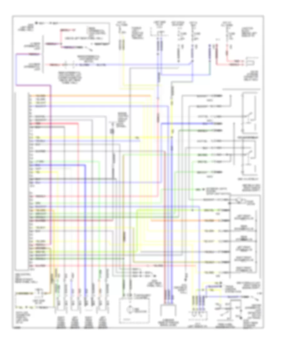
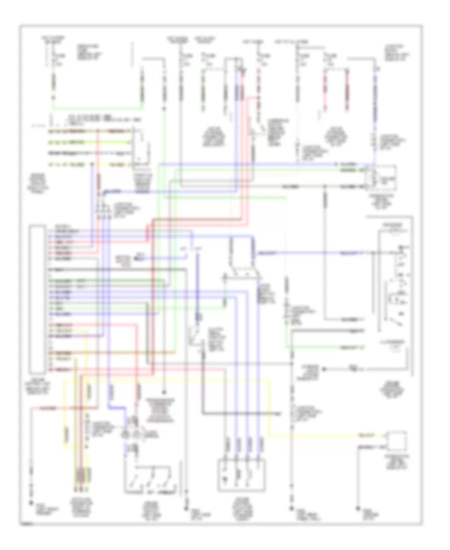
AIR CONDITIONING
A/C Wiring Diagram for Mitsubishi Montero SR 1996
 https://portal-diagnostov.com/license.html
Automotive Electricians Portal FZCO
Automotive Electricians Portal FZCO
https://portal-diagnostov.com/license.html
https://portal-diagnostov.com/license.html
Automotive Electricians Portal FZCO
Automotive Electricians Portal FZCO
List of elements for A/C Wiring Diagram for Mitsubishi Montero SR 1996:
- (1995 3.0l 12 valve)
- (except
- 1995 3.0l 12 valve)
- A/c
- A/c switch (center of i/p)
- Air conditioning compressor clutch relay (left side of engine compt)
- Air conditioning compressor magnetic clutch (front left of engine compt)
- Air cond. control unit (right side of i/p)
- Air conditioning engine coolant temperature switch (1995 3.0l 12 valve) (top of engine)
- Air inlet sensor (right side of i/p)
- Air thermo sensor (right side of i/p)
- Blower motor (right side of i/p)
- Blower motor relay
- Blower resistor (right side of i/p)
- Blower switch (center of i/p)
- C 1995 vftc
- C24
- C36
- C38
- Condenser fan motor (front left of engine compt)
- Condenser fan motor relay (left side of engine compt)
- Dual pressure switch (front left of engine compt)
- Eco
- Engine control module (right side of i/p)
- Fuse 16 25a
- Fuse 2 10a
- Fuse 3 10a
- Fuse 3 25a
- G100 (left front fender)
- G201 (right side of i/p)
- G202 (left side of i/p)
- Heat control illumination light (center of i/p)
- Hot at all times
- Hot in run
- Interior lights system (fuse #5)
- Interior lights system (rheostat)
- Junction block (left side of i/p)
- Off
- Relay box (left side of engine compt)
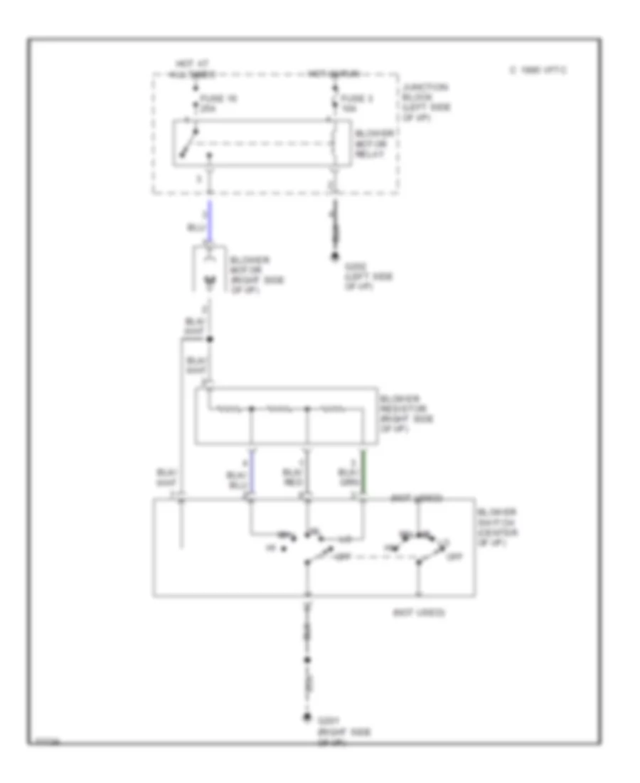
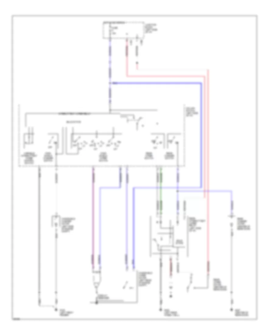
Heater Wiring Diagram for Mitsubishi Montero SR 1996
List of elements for Heater Wiring Diagram for Mitsubishi Montero SR 1996:
- (not used)
- Blower motor (right side of i/p)
- Blower motor relay
- Blower resistor (right side of i/p)
- Blower switch (center of i/p)
- C 1995 vftc
- Fuse 16 25a
- Fuse 3 10a
- G201 (right side of i/p)
- G202 (left side of i/p)
- Hot at all times
- Hot in run
- Junction block (left side of i/p)
- Off
ANTI-LOCK BRAKES
Anti-Lock Brakes Wiring Diagram for Mitsubishi Montero SR 1996
List of elements for Anti-Lock Brakes Wiring Diagram for Mitsubishi Montero SR 1996:
- (above left rear wheel well)
- (left side of i/p)
- (left side of i/p) j/c 3
- 60a
- A39
- A40
- A40-1
- A40-2
- Abs control unit (rear of right rear wheel well)
- Abs hydraulic unit (right side of engine compt.)
- Abs indicator
- Abs motor relay
- Abs relay box (right side of engine compt.)
- Abs valve relay
- C37
- C81
- C93
- C96
- Center differential lock detection switch (on trans.)
- Data link connector (partial) (left side of i/p)
- E13
- E14
- Engine control module (right kick panel)
- Exterior lights system (stop light switch)
- Free wheel engage switch
- Fuse 10a
- Fusible link 1 (positive battery terminal)
- G sensor (rear of parking brake lever)
- G105 (right rear of engine compt.)
- G121 (center of safety wall)
- G402 (left rear wheel well)
- Hot at all times
- Hot in run
- Hot in run or start
- Instrument cluster
- Iod or storage connector (relay box)
- J/c 1
- J/c 3 (left side of i/p)
- Junction block (behind left side of i/p)
- Left front exhaust valve
- Left front intake valve
- Left front wheel speed sensor
- Left rear wheel speed sensor
- Nca
- Pump motor
- Rear differential lock control unit
- Rear differential lock control unit jumper connector (above left rear wheel well)
- Rear differential lock detection switch
- Rear exhaust valve
- Rear intake valve
- Red
- Right front exhaust valve
- Right front intake valve
- Right front wheel speed sensor
- Right rear wheel speed sensor
- Trans- missions system (4wd)
- W/ rear differential lock
- W/o rear differential lock
Differential Lock Wiring Diagram for Mitsubishi Montero SR 1996
List of elements for Differential Lock Wiring Diagram for Mitsubishi Montero SR 1996:
- (left rear wheel well)
- Anti-lock brakes circuit
- C96
- Center differential lock operation detection switch (top of trans.)
- Fuse 10a
- G201 (right side of i/p)
- G206 (center of i/p)
- G402
- Hot in run
- Hot in run or start
- Illum- ination lamp
- Instrument cluster
- Interior lights system
- Junction block (below left side of i/p)
- Nca
- Off
- Pressure switch
- Pump motor
- R/d lock indicator
- Rear differential lock air pump
- Rear differential lock control unit (above left rear wheel well)
- Rear differential lock detection switch
- Rear differential lock switch
- Red
- Release valve
- Transmissions system (4wd)
- Vehicle speed sensor (reed switch)
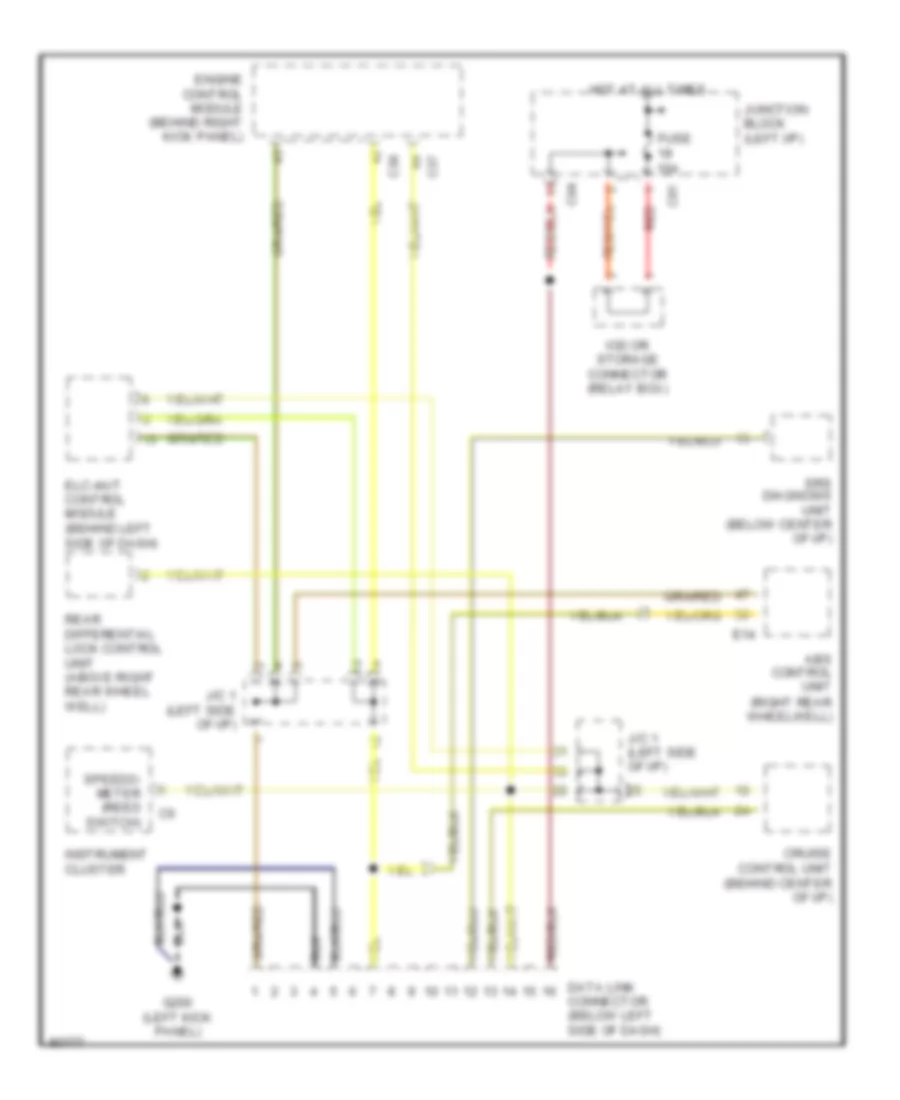
COMPUTER DATA LINES
Computer Data Lines for Mitsubishi Montero SR 1996
List of elements for Computer Data Lines for Mitsubishi Montero SR 1996:
- (right rear wheelwell)
- Abs control unit
- C37
- C38
- C81
- C94
- Cruise control unit (behind center of i/p)
- Data link connector (below left side of dash)
- E14
- Elc-4a/t control module (behind left
- Engine control module (behind right kick panel)
- Fuse 10a
- G200 (left kick panel)
- Hot at all times
- Instrument cluster
- Iod or storage connector (relay box)
- J/c 1 (left side of i/p)
- Junction block (left i/p)
- Rear differential lock control unit (above right rear wheel well)
- Red
- Side of dash)
- Speedo- meter (reed switch)
- Srs diagnosis unit (below center of i/p)
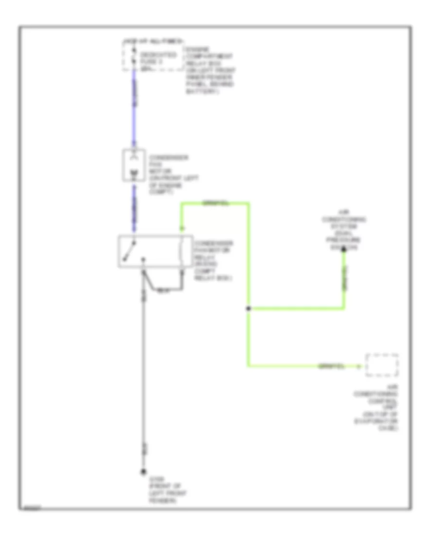
COOLING FAN
Cooling Fan Wiring Diagram for Mitsubishi Montero SR 1996
List of elements for Cooling Fan Wiring Diagram for Mitsubishi Montero SR 1996:
- Air conditioning control unit (on top of evaporator case)
- Air conditioning system (dual pressure switch)
- Condenser fan motor (on front left of engine compt)
- Condenser fan motor relay (in eng compt relay box)
- Dedicated fuse 3 25a
- Engine compartment relay box (on left front inner fender panel, behind battery)
- G100 (front of left front fender)
- Hot at all times
CRUISE CONTROL
Cruise Control Wiring Diagram for Mitsubishi Montero SR 1996
List of elements for Cruise Control Wiring Diagram for Mitsubishi Montero SR 1996:
- (a/t)
- (behind left side of i/p)
- 3.0l 12 valve (ex. 1996) 3.0l 24 valve (ex. 1996) & 3.5l (ex. 1996) 1996 all
- A/t
- C80
- C81
- C93
- C94
- C97
- Cancel
- Clock spring
- Clutch pedal position switch (below left i/p)
- Combination meter (left side of i/p)
- Combination meter (vss, left side of i/p)
- Cruise control actuator (left side of engine compt)
- Cruise control main switch (left side of i/p)
- Cruise control switch (left side of i/p))
- Cruise control unit
- Cruise ind
- Data link connector (right of steering column)
- Dedicated fuse (behind left side of i/p)
- Engine control module (right kick panel)
- Fuse 10a
- Fuse 15a
- G100 (left front fender)
- G202 (left side of i/p)
- G206 (center of i/p)
- G402 (left rear wheel well)
- Hot at all times
- Hot in acc
- Hot in park or head
- Hot in run
- Ignition switch pin 5
- Illumination
- Indicator
- Interior lights system (rheostat)
- Iod or storage connector (left side eng compt)
- Iod or storage connector (left side of i/p)
- Junction block
- Junction connector 1 (left side of i/p)
- Junction connector 2 (left side of i/p)
- Junction connector 3 (left side of i/p)
- M/t
- Off
- Or run
- Or start
- Overdrive switch (center console, behind shift lever)
- Red
- Resume
- Set
- Throttle position sensor (top of engine)
- Transmissions (overdrive control system/ automatic transmission)
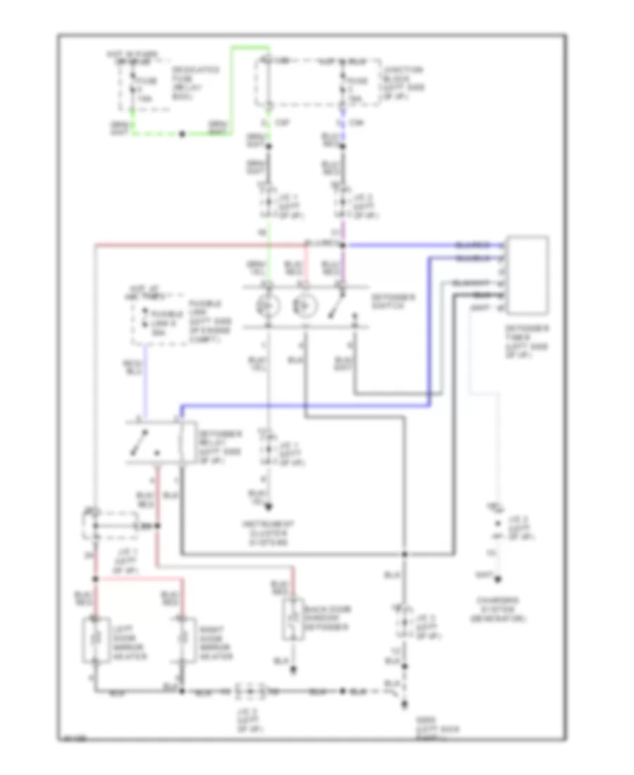
DEFOGGERS
Defogger Wiring Diagram for Mitsubishi Montero SR 1996
List of elements for Defogger Wiring Diagram for Mitsubishi Montero SR 1996:
- Back door window defogger
- C80
- C94
- C97
- Charging system (generator)
- Dedicated fuse (relay box)
- Defogger relay (left side of i/p)
- Defogger switch
- Defogger timer (left side of i/p)
- Fuse 10a
- Fusible link (left side of engine compt)
- Fusible link 9 30a
- G200 (left kick panel)
- Hot at all times
- Hot in park or head
- Hot in run
- Ill
- Ind
- Instrument cluster systems
- J/c 1 (left of i/p)
- J/c 2 (left of i/p)
- J/c 3 (left of i/p)
- Junction block (left side of i/p)
- Left door mirror heater
- Right door mirror heater
ELECTRONIC SUSPENSION
Electronic Suspension Wiring Diagram for Mitsubishi Montero SR 1996
List of elements for Electronic Suspension Wiring Diagram for Mitsubishi Montero SR 1996:
- C100
- C96
- Combination meter
- Dedicated fuse (relay box, beside battery)
- Except
- Fuse 10a
- G402 (left rear wheel well)
- Hot in on
- Hot in on or start
- Hot in park or head
- Interior lights system (rheostat)
- J/c 1 (left side of dash)
- Junction block (left side of dash)
- Left front shock absorber
- Left rear shock absorber
- Red
- Right front shock absorber
- Right rear shock absorber
- Shock absorber control switch (center of console)
- Variable shock absorber control unit (left rear quarter panel)
ENGINE PERFORMANCE
3.0L
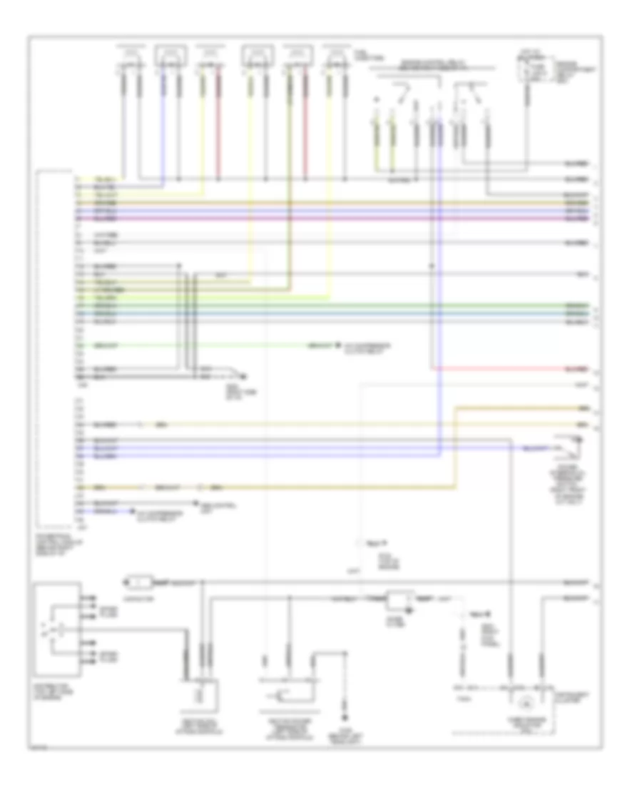
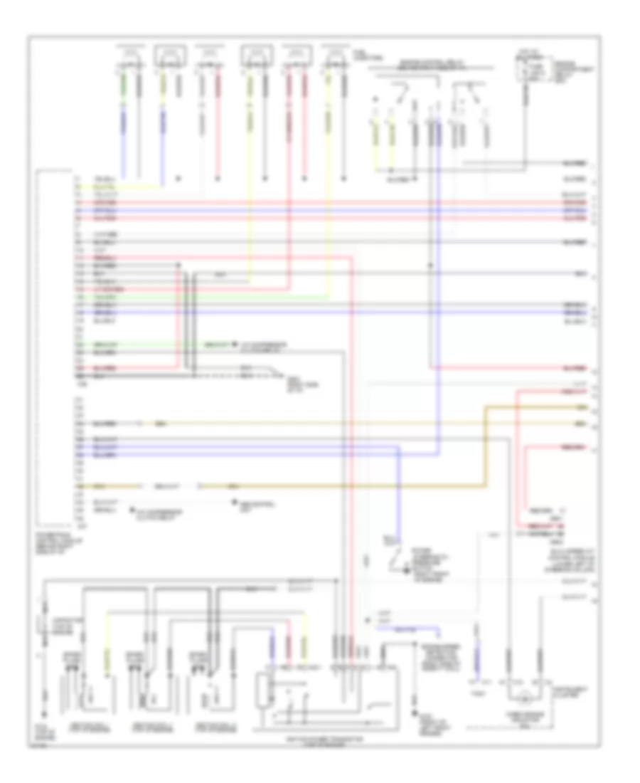
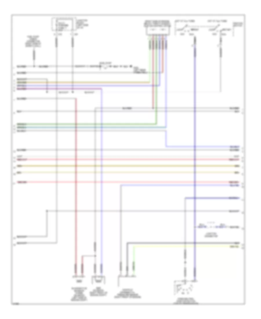
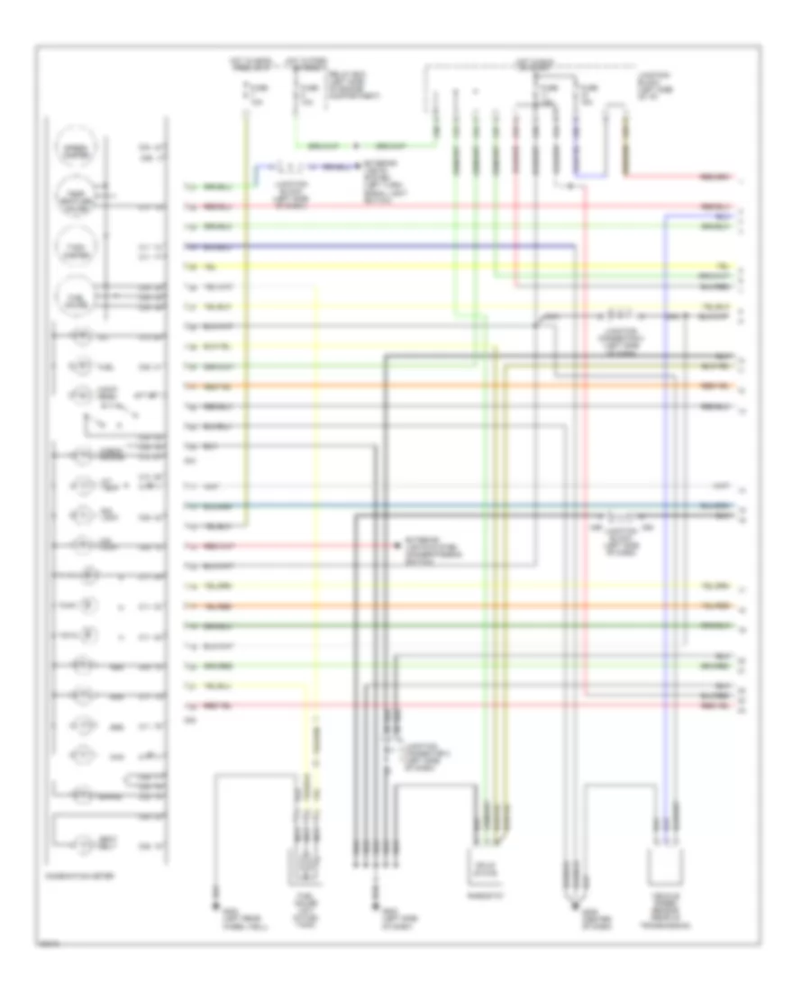
3.0L 12 Valve, Engine Performance Wiring Diagrams (1 of 3) for Mitsubishi Montero SR 1996
List of elements for 3.0L 12 Valve, Engine Performance Wiring Diagrams (1 of 3) for Mitsubishi Montero SR 1996:
- A/c compressor clutch relay
- Abs control unit
- C11
- C12
- C36
- C37
- Capacitor
- Check engine indicator (mil)
- Coil wire
- Distributor (top left side of engine)
- Engine compartment relay box
- Engine control relay (behind right side of i/p)
- Fuel injectors
- Fuse link 6 20a
- G106 (behind left headlight)
- G134 (top of engine)
- G202 (right side of i/p)
- G203 (right kick panel)
- Hot at all times
- Ignition coil (left side of intake manifold)
- Ignition power transistor (left side of intake manifold)
- Instrument cluster
- Nca
- Noise filter
- Power steering oil pressure switch (right front of engine) (a/t only)
- Powertrain control module (behind right side of i/p)
- Spark plugs
- Tach
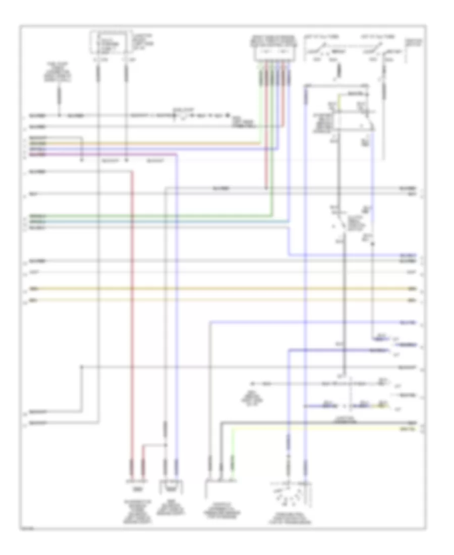
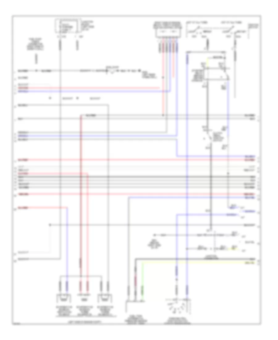
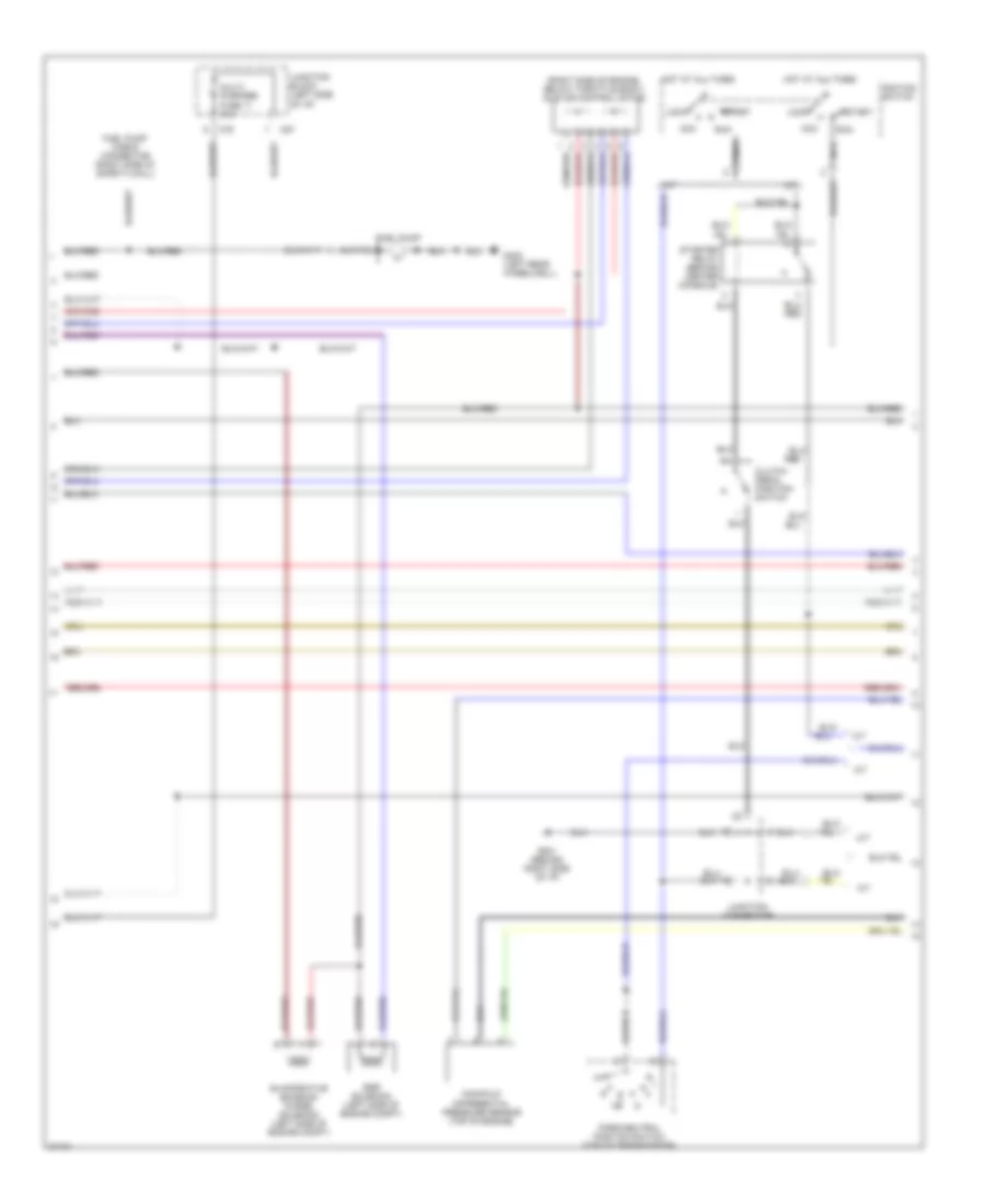
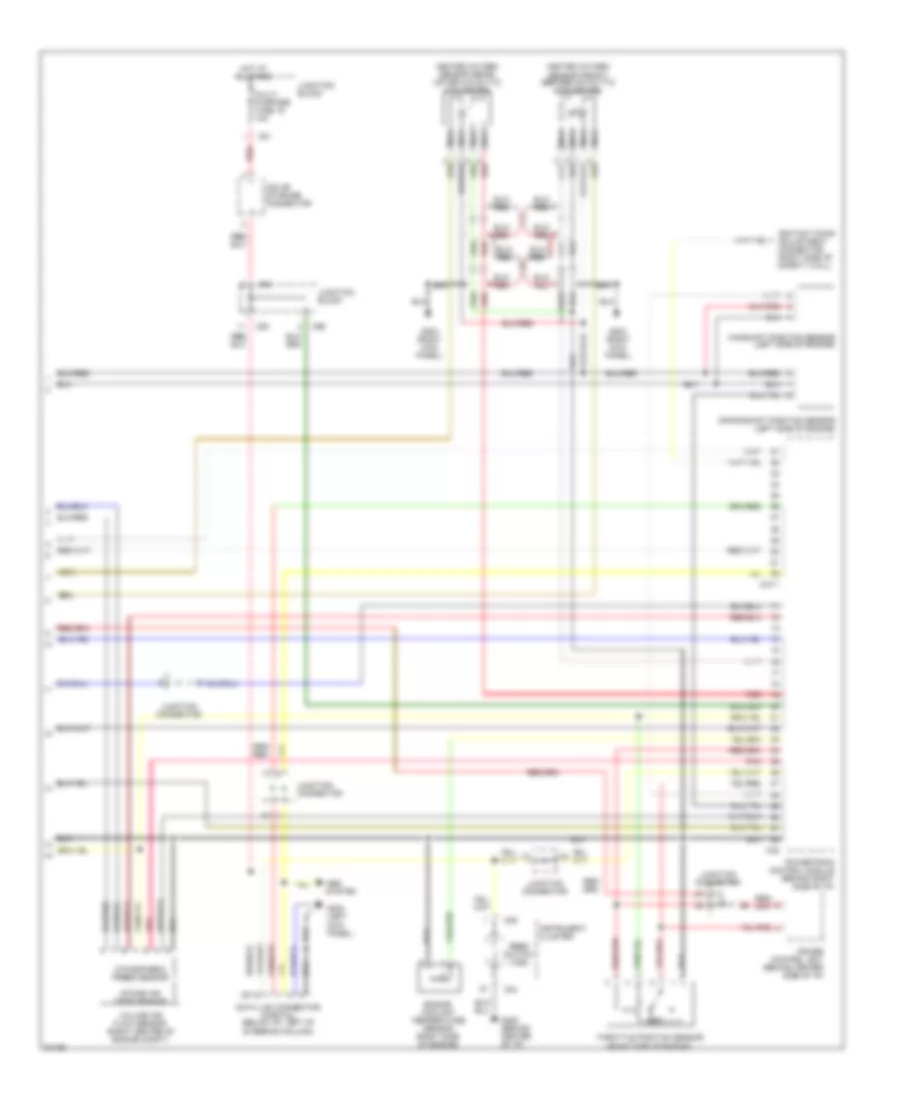
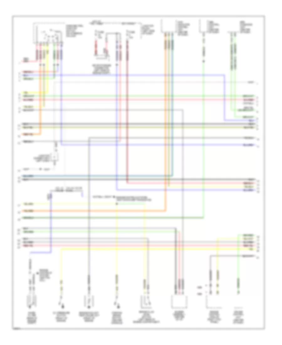
3.0L 12 Valve, Engine Performance Wiring Diagrams (2 of 3) for Mitsubishi Montero SR 1996
List of elements for 3.0L 12 Valve, Engine Performance Wiring Diagrams (2 of 3) for Mitsubishi Montero SR 1996:
- (right side of engine, below throttle body) idle air control motor
- A/t
- Acc
- C76
- C87
- Clutch pedal position switch
- Egr solenoid (left side of engine compt)
- Evaporative emission purge solenoid (left side of engine compt)
- Fuel pump
- Fuel pump check connector (right side of safety wall)
- G201 (behind right side of i/p)
- G402 (left rear wheelwell)
- Hot at all times
- Ignition switch
- Junction block (left side of i/p)
- Junction connector
- Lock
- M/t
- Manifold differential pressure sensor (top of engine)
- Multi- purpose fuse 11 10a
- Nca
- Park/neutral position switch (top of transmission)
- Red
- Run
- Start
- Starter relay (behind center console)
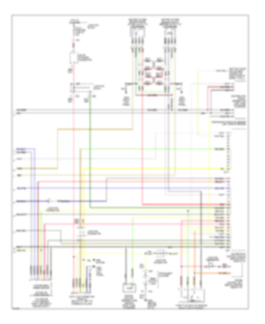
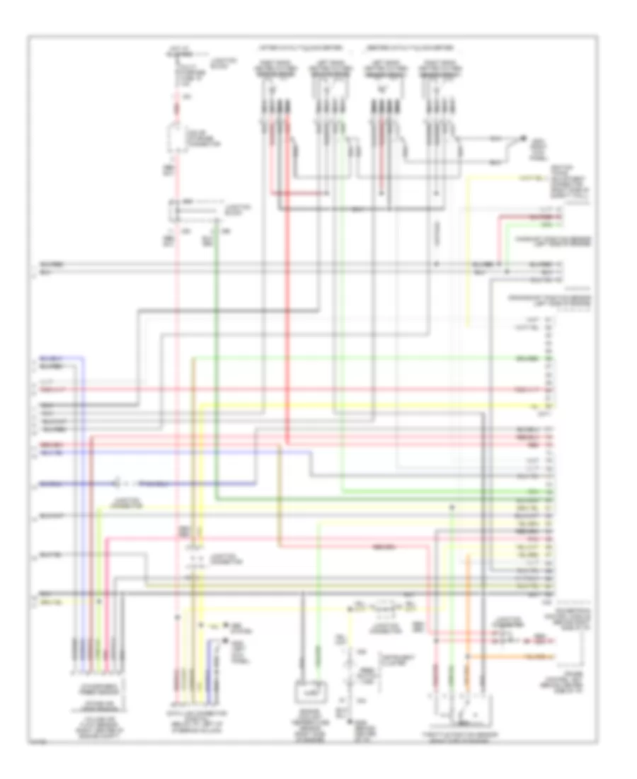
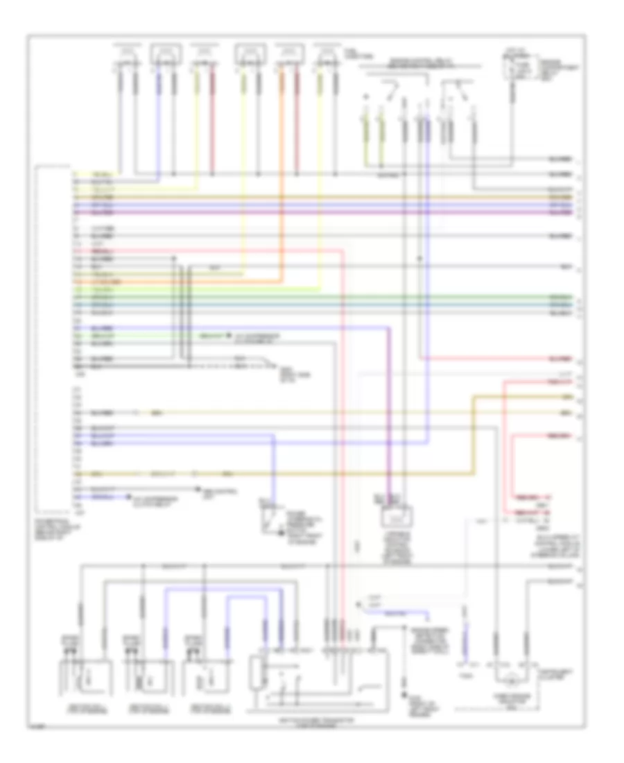
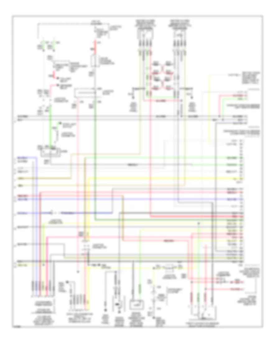
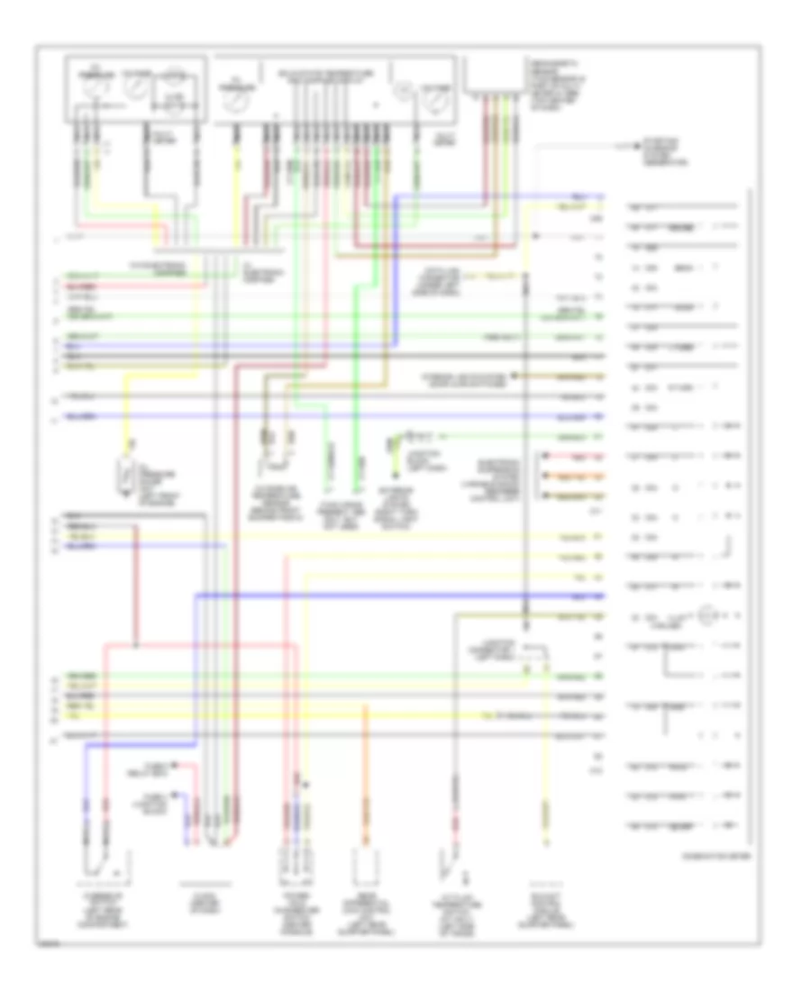
3.0L 12 Valve, Engine Performance Wiring Diagrams (3 of 3) for Mitsubishi Montero SR 1996
List of elements for 3.0L 12 Valve, Engine Performance Wiring Diagrams (3 of 3) for Mitsubishi Montero SR 1996:
- Abs system
- Atmospheric press sensor
- C04
- C06
- C37-1
- C38
- C81
- C94
- C96
- Crankshaft position sensor (left side of engine)
- Cruise control unit (behind center side of i/p)
- Data link connector (partial) (below i/p, left of steering column)
- Distributor signal generator (left side of engine)
- Engine coolant temperature sensor (right side of engine)
- G200 (left kick panel)
- G203 (right kick panel)
- G206 (behind center of i/p)
- Heated oxygen sensor (front) (before catalytic converter)
- Heated oxygen sensor (rear) (after catalytic converter)
- Hot at all times
- Ignition timing adjustment connector (right side of safety wall)
- Instrument cluster
- Intake air temp sensor
- Iod or storage connector
- Junction block
- Junction connector
- Multi- purpose fuse 19 10a
- Nca
- Pnk
- Powertrain control module (behind right side of i/p)
- Red
- Reed switch (vss)
- Throttle position sensor (right side of engine)
- Volume air flow sensor (right center of engine compt)
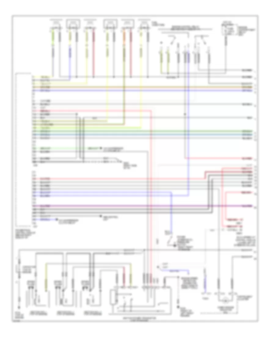
3.0L 24 Valve, Engine Performance Wiring Diagrams, California (1 of 3) for Mitsubishi Montero SR 1996
List of elements for 3.0L 24 Valve, Engine Performance Wiring Diagrams, California (1 of 3) for Mitsubishi Montero SR 1996:
- (right front
- A/c compressor clutch relay
- A42
- A42-1
- Abs control unit
- C11
- C12
- C36
- C37
- C66-1
- C66-8
- Capacitor (top of engine)
- Check engine indicator (mil)
- Elc-4 speed a/t control module (lower left of steering column)
- Engine compartment relay box
- Engine control relay (behind right side of i/p)
- Engine speed detection connector (right side of safety wall)
- Fuel injectors
- Fuse link 6 20a
- G100 (front of left front fender)
- G134 (top of engine)
- G202 (right side of i/p)
- Hot at all times
- Ignition coil i (top of engine)
- Ignition coil ii (top of engine)
- Ignition coil iii (top of engine)
- Ignition power transistor (top of engine)
- Instrument cluster
- Nca
- Of engine)
- Power
- Powertrain control module (behind right side of i/p)
- Pressure
- Spark plugs 1 & 4
- Spark plugs 2 & 5
- Spark plugs 3 & 6
- Steering oil
- Switch
- Tach
3.0L 24 Valve, Engine Performance Wiring Diagrams, California (2 of 3) for Mitsubishi Montero SR 1996
List of elements for 3.0L 24 Valve, Engine Performance Wiring Diagrams, California (2 of 3) for Mitsubishi Montero SR 1996:
- (left side of engine compt)
- (right side of engine, below throttle body) idle air control motor
- A/t
- Acc
- C76
- C87
- Clutch pedal position switch
- Evaporative emission purge solenoid (l)
- Evaporative emission purge solenoid (s)
- Evaporative emission ventilation solenoid
- Fuel pump
- Fuel pump check connector (right side of safety wall)
- Fuel tank differential pressure sensor (on fuel tank)
- G201 (behind right side of i/p)
- G402 (left rear wheelwell)
- Hot at all times
- Ignition switch
- Junction block (left side of i/p)
- Junction connector
- Lock
- M/t
- Multi- purpose fuse 11 10a
- Nca
- Park/neutral position switch (top of transmission)
- Red
- Run
- Start
- Starter relay (behind center console)
3.0L 24 Valve, Engine Performance Wiring Diagrams, California (3 of 3) for Mitsubishi Montero SR 1996
List of elements for 3.0L 24 Valve, Engine Performance Wiring Diagrams, California (3 of 3) for Mitsubishi Montero SR 1996:
- (after catalytic converter)
- (before catalytic converter)
- Abs system
- Atmospheric press sensor
- C04
- C06
- C37-1
- C38
- C81
- C94
- C96
- Camshaft position sensor (left side of engine)
- Crankshaft position sensor (left side of engine)
- Cruise control unit (behind center side of i/p)
- Data link connector (partial) (below i/p, left of steering column)
- Engine coolant temperature sensor (right side of engine)
- G200 (left kick panel)
- G203 (right kick panel)
- G206 (behind center of i/p)
- Hot at all times
- Ignition timing adjustment connector (right side of safety wall)
- Instrument cluster
- Intake air temp sensor
- Iod or storage connector
- Junction block
- Junction connector
- Left bank heated oxygen sensor (front)
- Left bank heated oxygen sensor (rear)
- Multi- purpose fuse 19 10a
- Nca
- Pnk
- Powertrain control module (behind right side of i/p)
- Red
- Reed switch (vss)
- Right bank heated oxygen sensor (front)
- Right bank heated oxygen sensor (rear)
- Throttle position sensor (right side of engine)
- Volume air flow sensor (right center of engine compt)
3.0L 24 Valve, Engine Performance Wiring Diagrams, Federal (1 of 3) for Mitsubishi Montero SR 1996
List of elements for 3.0L 24 Valve, Engine Performance Wiring Diagrams, Federal (1 of 3) for Mitsubishi Montero SR 1996:
- (right front
- A/c compressor clutch relay
- A42
- A42-1
- Abs control unit
- C11
- C12
- C36
- C37
- C66-1
- C66-8
- Capacitor (top of engine)
- Check engine indicator (mil)
- Elc-4 speed a/t control module (lower left of steering column)
- Engine compartment relay box
- Engine control relay (behind right side of i/p)
- Engine speed detection connector (right side of safety wall)
- Fuel injectors
- Fuse link 6 20a
- G100 (front of left front fender)
- G134 (top of engine)
- G202 (right side of i/p)
- Hot at all times
- Ignition coil i (top of engine)
- Ignition coil ii (top of engine)
- Ignition coil iii (top of engine)
- Ignition power transistor (top of engine)
- Instrument cluster
- Nca
- Of engine)
- Power
- Powertrain control module (behind right side of i/p)
- Pressure
- Spark plugs 1 & 4
- Spark plugs 2 & 5
- Spark plugs 3 & 6
- Steering oil
- Switch
- Tach
3.0L 24 Valve, Engine Performance Wiring Diagrams, Federal (2 of 3) for Mitsubishi Montero SR 1996
List of elements for 3.0L 24 Valve, Engine Performance Wiring Diagrams, Federal (2 of 3) for Mitsubishi Montero SR 1996:
- (right side of engine, below throttle body) idle air control motor
- A/t
- Acc
- C76
- C87
- Clutch pedal position switch
- Egr solenoid (left side of engine compt)
- Evaporative emission purge solenoid (left side of engine compt)
- Fuel pump
- Fuel pump check connector (right side of safety wall)
- G201 (behind right side of i/p)
- G402 (left rear wheelwell)
- Hot at all times
- Ignition switch
- Junction block (left side of i/p)
- Junction connector
- Lock
- M/t
- Manifold differential pressure sensor (top of engine)
- Multi- purpose fuse 11 10a
- Nca
- Park/neutral position switch (top of transmission)
- Red
- Run
- Start
- Starter relay (behind center console)
3.0L 24 Valve, Engine Performance Wiring Diagrams, Federal (3 of 3) for Mitsubishi Montero SR 1996
List of elements for 3.0L 24 Valve, Engine Performance Wiring Diagrams, Federal (3 of 3) for Mitsubishi Montero SR 1996:
- Abs system
- Atmospheric press sensor
- C04
- C06
- C37-1
- C38
- C81
- C94
- C96
- Camshaft position sensor (left side of engine)
- Crankshaft position sensor (left side of engine)
- Cruise control unit (behind center side of i/p)
- Data link connector (partial) (below i/p, left of steering column)
- Engine coolant temperature sensor (right side of engine)
- G200 (left kick panel)
- G203 (right kick panel)
- G206 (behind center of i/p)
- Heated oxygen sensor (front) (before catalytic converter)
- Heated oxygen sensor (rear) (after catalytic converter)
- Hot at all times
- Ignition timing adjustment connector (right side of safety wall)
- Instrument cluster
- Intake air temp sensor
- Iod or storage connector
- Junction block
- Junction connector
- Multi- purpose fuse 19 10a
- Nca
- Pnk
- Powertrain control module (behind right side of i/p)
- Red
- Reed switch (vss)
- Throttle position sensor (right side of engine)
- Volume air flow sensor (right center of engine compt)
3.5L
3.5L, Engine Performance Wiring Diagrams (1 of 3) for Mitsubishi Montero SR 1996
List of elements for 3.5L, Engine Performance Wiring Diagrams (1 of 3) for Mitsubishi Montero SR 1996:
- (right front
- A/c compressor clutch relay
- A42
- A42-1
- Abs control unit
- C11
- C12
- C36
- C37
- C66-1
- C66-8
- Check engine indicator (mil)
- Elc-4 speed a/t control module (lower left of steering column)
- Engine compartment relay box
- Engine control relay (behind right side of i/p)
- Engine speed detection connector (right side of safety wall)
- Fuel injectors
- Fuse link 6 20a
- G100 (front of left front fender)
- G202 (right side of i/p)
- Hot at all times
- Ignition coil i (top of engine)
- Ignition coil ii (top of engine)
- Ignition coil iii (top of engine)
- Ignition power transistor (top of engine)
- Instrument cluster
- Of engine)
- Power
- Powertrain control module (behind right side of i/p)
- Pressure
- Spark plugs 1 & 4
- Spark plugs 2 & 5
- Spark plugs 3 & 6
- Steering oil
- Switch
- Tach
- Variable induction control solenoid (left front of engine)
3.5L, Engine Performance Wiring Diagrams (2 of 3) for Mitsubishi Montero SR 1996
List of elements for 3.5L, Engine Performance Wiring Diagrams (2 of 3) for Mitsubishi Montero SR 1996:
- (right side of engine, below throttle body) idle air control motor
- Acc
- C76
- C87
- Egr solenoid (right front of engine compt)
- Evaporative emission purge solenoid (left side of engine compt)
- Fuel pump
- Fuel pump check connector (right side of safety wall)
- G402 (left rear wheelwell)
- Hot at all times
- Ignition switch
- Junction block (left side of i/p)
- Junction connector
- Lock
- Manifold differential pressure sensor (right front of engine)
- Multi- purpose fuse 11 10a
- Nca
- Park/neutral position switch (top of transmission)
- Run
- Start
3.5L, Engine Performance Wiring Diagrams (3 of 3) for Mitsubishi Montero SR 1996
List of elements for 3.5L, Engine Performance Wiring Diagrams (3 of 3) for Mitsubishi Montero SR 1996:
- Abs system
- Atmospheric press sensor
- C04
- C06
- C37-1
- C38
- C80
- C81
- C81 junction block
- C94
- C96
- C97
- Camshaft position sensor (left side of engine)
- Crankshaft position sensor (lower front of engine)
- Cruise control unit (behind center side of i/p)
- Data link connector (partial) (below i/p, left of steering column)
- Dedicated fuse 5 15a
- Defogger relay
- Diode
- Engine compartment relay box
- Engine coolant temperature sensor (right side of engine)
- G200 (left kick panel)
- G203 (right kick panel)
- G206 (behind center of i/p)
- Heated oxygen sensor (front) (before catalytic converter)
- Heated oxygen sensor (rear) (after catalytic converter)
- Hot at all times
- Ignition timing adjustment connector (right side of safety wall)
- Instrument cluster
- Intake air temp sensor
- Iod or storage connector
- Junction block
- Junction connector
- Knock sensor (top of engine)
- Multi- purpose fuse 19 10a
- Nca
- Pnk
- Powertrain control module (behind right side of i/p)
- Red
- Reed switch (vss)
- Stop light switch
- Taillight relay
- Throttle position sensor (right side of engine)
- Volume air flow sensor (right center of engine compt)
EXTERIOR LIGHTS
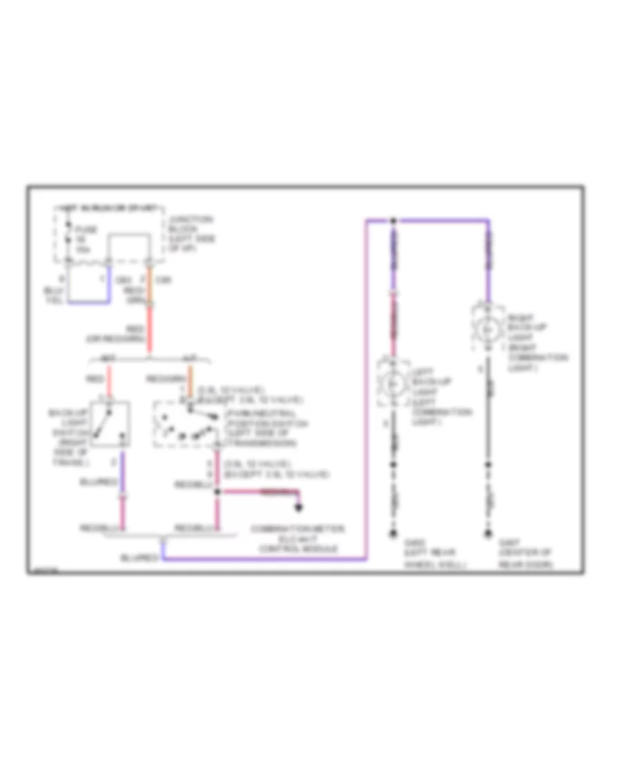
Back-up Lamps Wiring Diagram for Mitsubishi Montero SR 1996
List of elements for Back-up Lamps Wiring Diagram for Mitsubishi Montero SR 1996:
- (3.0l 12 valve) (except 3.0l 12 valve)
- A/t
- Back-up light switch (right side of trans.)
- C80
- C95
- Combination meter, elc-4a/t control module
- Fuse 15a
- G402 (left rear
- G407 (center of
- Hot in run or start
- Junction block (left side of i/p)
- Left back-up light (left combination light)
- M/t
- Park/neutral position switch (left side of transmission)
- R n
- Rear door)
- Red
- Right back-up light (right combination light)
- Wheel well)
Exterior Lamps Wiring Diagram (1 of 2) for Mitsubishi Montero SR 1996
List of elements for Exterior Lamps Wiring Diagram (1 of 2) for Mitsubishi Montero SR 1996:
- C100
- C57
- C80
- C94
- Column switch (lighting switch) (left side of i/p)
- From column switch
- From junction block
- Fuse 10a
- Fusible link (left side of engine compt)
- Fusible link 40a
- G100 (left front fender)
- G103 (right shock tower)
- G402 (left rear wheel well)
- G407 (center of rear door)
- Head
- High mounted stop light
- Hot at all times
- Junction block (left side of i/p)
- Junction connector 2 (left side of i/p)
- Junction connector 3 (left side of i/p)
- Left front combination light
- Left license light
- Left rear combination light
- Marker
- Off
- Red
- Relay box (left side of engine compt)
- Right front combination light
- Right license light
- Right rear combination light
- Stop light switch (brake pedal support)
- Stop/ tail
- Tail
- Tail light relay (relay box) (left side of engine compt)
- Turn
- W/ cruise control
- W/o cruise control
Exterior Lamps Wiring Diagram (2 of 2) for Mitsubishi Montero SR 1996
List of elements for Exterior Lamps Wiring Diagram (2 of 2) for Mitsubishi Montero SR 1996:
- C04
- C11
- C80
- C93
- C97
- Column switch (turn-signal light switch) (left side of i/p)
- Combination meter
- Fuse 10a
- G202 (left side of i/p)
- Hazard light switch
- Hot at all times
- Hot in park or head
- Hot in run or start
- Ill
- Junction block (left side of i/p)
- Off
- Relay box (left side of engine compt)
- Rheostat
- Solid state
- To left front combination light
- To left rear comb light
- To right front combination light
- To right rear comb light
- Turn
- Turn- signal and hazard flasher unit (left side of i/p)
GROUND DISTRIBUTION
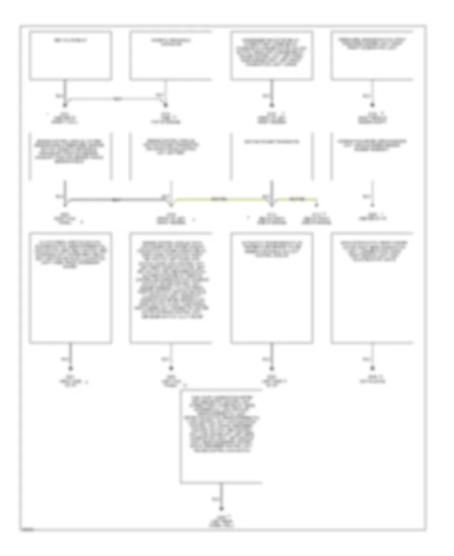
Ground Distribution Wiring Diagram for Mitsubishi Montero SR 1996
List of elements for Ground Distribution Wiring Diagram for Mitsubishi Montero SR 1996:
- Abs valve relay
- Automatic transmission fluid temperature sensor, pulse generator shield, elc-4a/t control module
- Back door switch, rear washer motor, right rear combination light, license plate lamps, right backup light, high mounted stop lights
- Clutch pedal position switch, blower switch, rear differential lock switch, seat belt switch, srs diagnosis unit, power seat relay box, ignition keyhole illumination light timer, front accessory socket
- Combination meter, srs diagnosis unit, vehicle speed sensor, buzzer assembly
- Condenser fan motor relay, intermittent wiper relay, windshield washer motor, column switch, headlight washer relay, cruise control unit, left park/ side marker light, left front combination light, horns
- Engine control module, data link connector, power window main switch, power window relay, right door lock switch, right key switch, left door lock switch, door lock control unit, left front door actuator, left key switch, key reminder switch, blower motor relay, remote controlled mirror switch, sunroof switch, cruise control unit, buzzer assembly, clutch pedal position switch, ignition keyhole illumination light, rheostat, combination meter, brake fluid level switch, clock, turn signal and flasher unit, cigarette lighter, motor antenna control unit, defogger switch, multi meter
- Engine control module, ignition power transistor, air conditioning control unit, battery
- Engine control module, oxygen sensor shield, freewheel engage switch, noise filter shiels, crankshaft position sensor, camshaft position sensor, knock sensor shield
- Freewheel engage switch, right park/side marker light, right front combination light
- Fuel pump, combination meter keyless entry control unit, intermittent wiper relay, rear differential lock air pump, rear differential lock detection switch, rear differential lock control unit, 4wd indicator, control unit, shock absorber, control switch, abs control unit, fuel gauge unit, left rear combination light, left backup light, rear accessory socket, shock absorber control unit, cruise control main switch
- G100 (front of left front fender)
- G105 (right rear of engine compt)
- G112 (below right side of engine)
- G121 (center of safety wall)
- G134 (1996) (top of engine)
- G200 (left kick panel)
- G201 (right side of i/p)
- G202 (left side of i/p)
- G203 (right kick panel)
- G206 (center of i/p)
- G402 (left rear wheel well)
- G406 (on tailgate)
- Ignition power transistor,
- Noise filter shield, capacitor
HEADLIGHTS
Headlight Wiring Diagram for Mitsubishi Montero SR 1996
List of elements for Headlight Wiring Diagram for Mitsubishi Montero SR 1996:
- 10a
- C57
- C58
- Column switch
- Dedicated fuses (relay box) (left side of engine compt)
- Dimmer/ passing switch
- Fuse
- Fusible link (relay box) (left side of engine compt)
- Fusible link 13 40a
- G100 (front of left front fender)
- Head
- Headlight relay (relay box) (left side of engine compt)
- Hi beam indicator
- Hot at all times
- Instrument cluster
- Left headlight
- Lighting switch
- Off
- Red
- Right headlight
- Tail
HORN
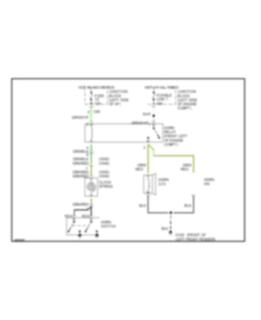
Horn Wiring Diagram for Mitsubishi Montero SR 1996
List of elements for Horn Wiring Diagram for Mitsubishi Montero SR 1996:
- (1995) (1996)
- (front of
- C80
- Clock spring
- Fuse 10a
- Fusible link 7 40a
- G100 left front fender)
- Horn (hi)
- Horn (lo)
- Horn relay (front left of engine compt)
- Horn switch
- Hot at all times
- Hot in acc or run
- Junction block (left side of engine compt)
- Junction block (left side of i/p)
- Nca
- Red
INSTRUMENT CLUSTER
Instrument Cluster Wiring Diagram (1 of 3) for Mitsubishi Montero SR 1996
List of elements for Instrument Cluster Wiring Diagram (1 of 3) for Mitsubishi Montero SR 1996:
- (rear of transmission)
- A/t temp
- Abs
- Brake
- C/d lock
- C04
- C04 34
- C04 36
- C04 38
- C04 43
- C04 44
- C05
- C05 11
- C05 12
- C05 15
- C05 16
- C05 18
- C05 19
- C05 20
- C05 21
- C05 22
- C06 2
- C11 71
- C11 74
- C11 75
- C11 76
- C11 77
- C11 79
- C11 82
- C11 83
- C11 84
- C12 55
- C12 60
- C12 61
- C80
- C93
- C94
- C95
- C96
- C97
- Check engine
- Chg
- Combination meter
- Exterior lights system (dimmer/passing switch)
- Exterior lights system (left turn- signal light switch)
- Fuel
- Fuel gauge
- Fuel gauge unit (in fuel tank)
- Fuse 10a
- Fuse 15a
- G202 (left side of dash)
- G206 (center of dash)
- G402 (left rear wheel well)
- Hot in head, pass or hi
- Hot in park or head
- Hot in run or start
- Junction block (left side of dash)
- Junction block (left side of i/p)
- Junction connector 2 (left side of dash)
- Junction connector 3 (left side of dash)
- Maint reqd
- Nca
- Oil
- R/d lock
- Relay box (left side of engine compartment)
- Rheostat
- Seat belt
- Solid state
- Speed- ometer
- Srs
- Tach- ometer
- Temp- erature gauge
- Vehicle speed sensor
Instrument Cluster Wiring Diagram (2 of 3) for Mitsubishi Montero SR 1996
List of elements for Instrument Cluster Wiring Diagram (2 of 3) for Mitsubishi Montero SR 1996:
- (1995 only)
- (center of dash)
- 3.0l 12 valve
- 3.0l 24 valve & 3.5l
- 4wd indicator control unit (center of dash)
- A31
- A45
- A46
- A59
- Abs control unit (center of dash)
- Brake fluid level switch (left rear of engine compartment)
- Buzzer assembly (center of i/p)
- C13
- C81
- C93
- C96
- C97
- Cruise control unit
- D18
- Engine control module (right kick panel)
- Engine controls system (ignition coil)
- Engine controls system (ignition power transistor)
- Engine coolant temp gauge unit (front of engine)
- Fuse 10a
- Hot at all times
- Hot in run
- Iod or storage connector (left side of engine compt)
- Junction block (left side of dash)
- Junction connector 2 (left dash)
- Noise filter (rear of engine compt)
- Oil pressure switch (front of engine)
- Park/neutral position switch (on steering column)
- Parking brake switch (center console)
- Red
- Red/
- Srs diagnosis unit (center of dash)
Instrument Cluster Wiring Diagram (3 of 3) for Mitsubishi Montero SR 1996
List of elements for Instrument Cluster Wiring Diagram (3 of 3) for Mitsubishi Montero SR 1996:
- (1995 only)
- (4 bulbs)
- (this wiring present 1995 only, but not used)
- 2wd
- 4wd
- A/t fluid temperature switch (a/t only) (left side of trans)
- Beam
- C04
- C05
- C06
- C11
- C12
- Clock (center of dash)
- Combination meter
- Cruise
- Data link connector (under left side of dash)
- Door
- Elc-4a/t control module (left rear quarter panel)
- Electronic suspension system (variable shock absorber control unit)
- Exterior lights system (right turn- signal light switch)
- Fuse 4 (junction block)
- Fuse 5 (relay box)
- Geomagnetic sensor (this sensor is part of multi- meter in 1996) (top center of dash)
- Hold
- Illum
- Illum.
- Interior lights system (door ajar switches)
- Junction block (left dash)
- Junction connector 1 (left dash)
- L turn
- Multi meter
- Nca
- Od off
- Oil pressure
- Oil pressure gauge unit (left front of engine)
- Outside air temperature sensor (behind front bumper fascia)
- Overdrive switch (left rear of engine compartment)
- Power/ hold changeover switch (center console)
- Pwr
- R turn
- Rear differential lock control unit (left rear quarter panel)
- Red
- Solid state temperature and compass display
- Starting/ charging system (generator)
- Voltage
- W/ electronic compass
- W/o electronic compass
INTERIOR LIGHTS
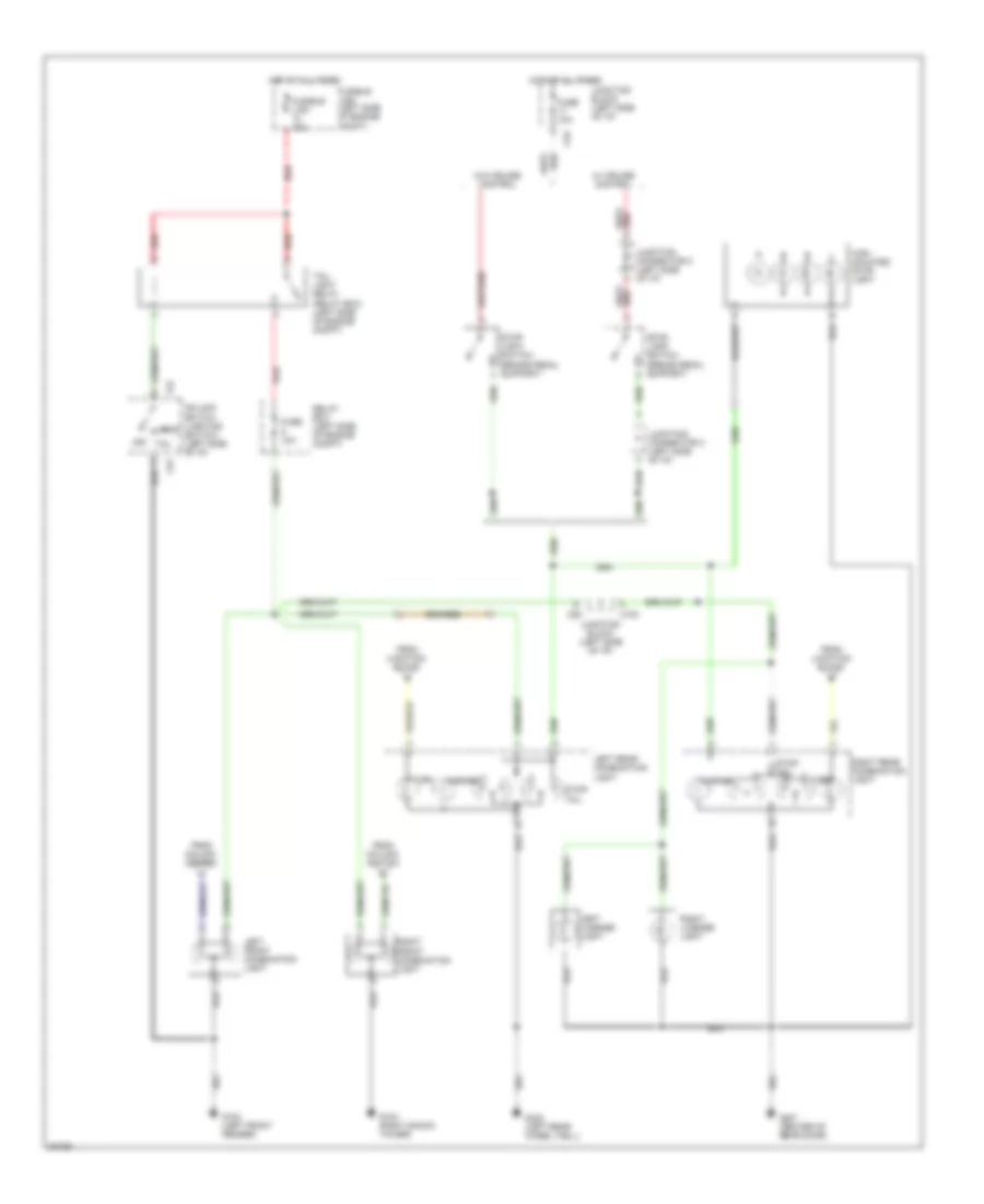
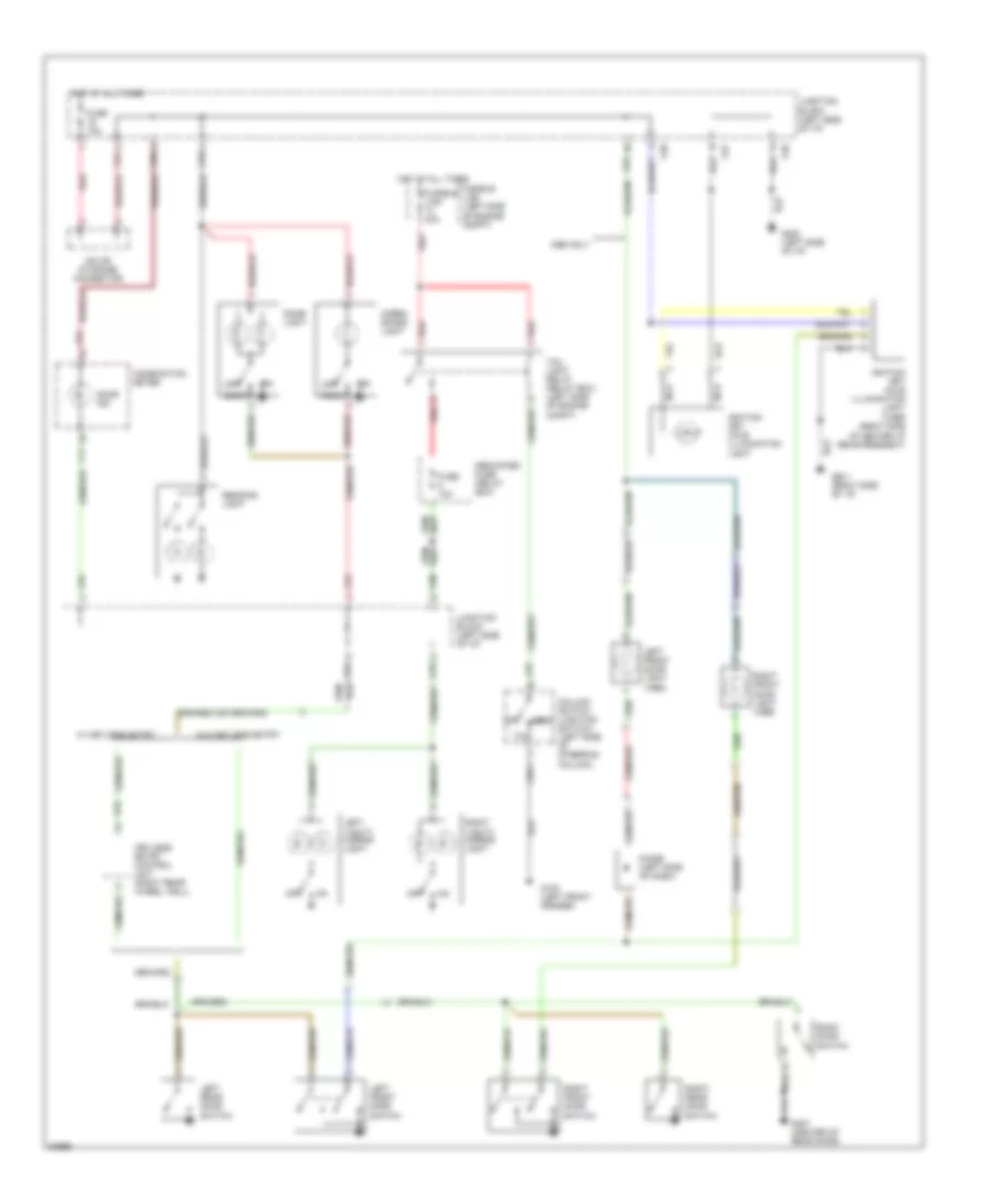
Courtesy Lamps Wiring Diagram for Mitsubishi Montero SR 1996
List of elements for Courtesy Lamps Wiring Diagram for Mitsubishi Montero SR 1996:
- 1996 only
- Back door switch
- C04
- C57
- C58-1
- C78
- C80
- C81
- C93
- C94
- C95
- C96
- C97
- Cargo space light
- Column switch (lighting switch) (left side of steering column)
- Combination meter
- Dedicated fuse (relay box)
- Diode (left side of dash)
- Dome light
- Door
- Door ind
- E15
- Fuse 10a
- Fusible link (left side of engine compt)
- Fusible link 40a
- G100 (left front fender)
- G201 (right side of i/p)
- G202 (left side of i/p)
- G407 (center of rear door)
- Head
- Hot at all times
- Ignition key hole illumination light
- Ignition key hole illumination light timer (right side of center i/p reinforcement)
- Iod or storage connector
- Junction block (left side of i/p)
- Keyless entry control unit (right rear wheel well)
- Left front door light (1996)
- Left front door switch
- Left rear door switch
- Left vanity mirror light
- Nca
- Off
- Reading light
- Red
- Right front door light (1996)
- Right front door switch
- Right rear door switch
- Right vanity mirror light
- Room
- Tail
- Tail light relay (relay box) (left side of engine compt)
- W/ keyless entry
- W/o keyless entry
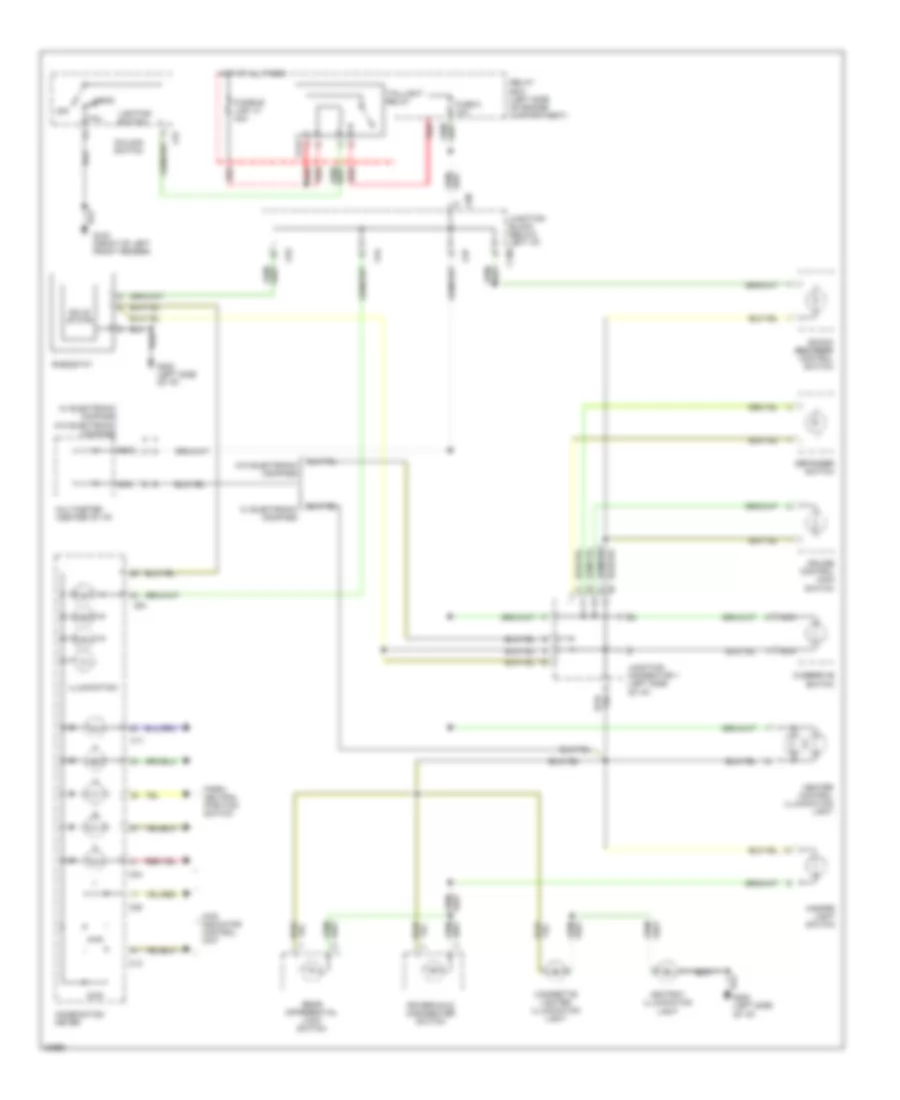
Instrument Illumination Wiring Diagram for Mitsubishi Montero SR 1996
List of elements for Instrument Illumination Wiring Diagram for Mitsubishi Montero SR 1996:
- 2wd
- 4wd
- 4wd indicator control unit
- A14x
- Ashtray illumination light
- C04
- C05
- C100
- C11
- C12
- C57
- C80
- C93
- C94
- C97
- Cigarette lighter illumination light
- Column switch
- Combination meter
- Cruise control main switch
- Defogger switch
- Fuse 5 10a
- Fusible link 13 40a
- G100 (front of left front fender)
- G202 (left side of i/p)
- Hazard light switch
- Head
- Heater control illumination light
- Hot at all times
- Illumination
- Junction block (below left i/p)
- Junction connector 1 (left side of i/p)
- Lighting switch
- Multimeter (center of i/p)
- Nca
- Off
- Overdrive switch
- Park/ neutral position switch
- Power/hold changeover switch
- Rear differential lock switch
- Red
- Relay box (left side of engine compartment)
- Rheostat
- Shock absorber control switch
- Solid state
- Tail
- Taillight relay
- W/ electronic compass
- W/o electronic compass
POWER ANTENNA
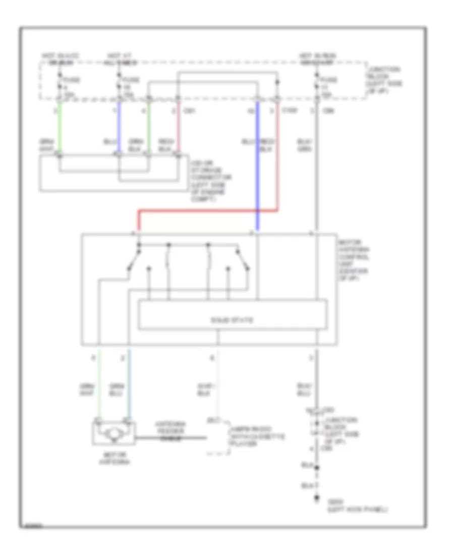
Power Antenna Wiring Diagram for Mitsubishi Montero SR 1996
List of elements for Power Antenna Wiring Diagram for Mitsubishi Montero SR 1996:
- Am/fm radio with cassette player
- Antenna feeder cable
- C100
- C81
- C93
- C95
- C98
- Fuse 10a
- G200 (left kick panel)
- Hot at all times
- Hot in acc or run
- Hot in run or start
- Iod or storage connector (left side of engine compt)
- Junction block (left side of i/p)
- Motor antenna
- Motor antenna control unit (center of i/p)
- Solid state
POWER DISTRIBUTION
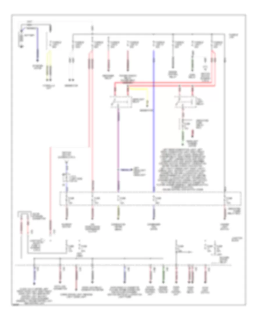
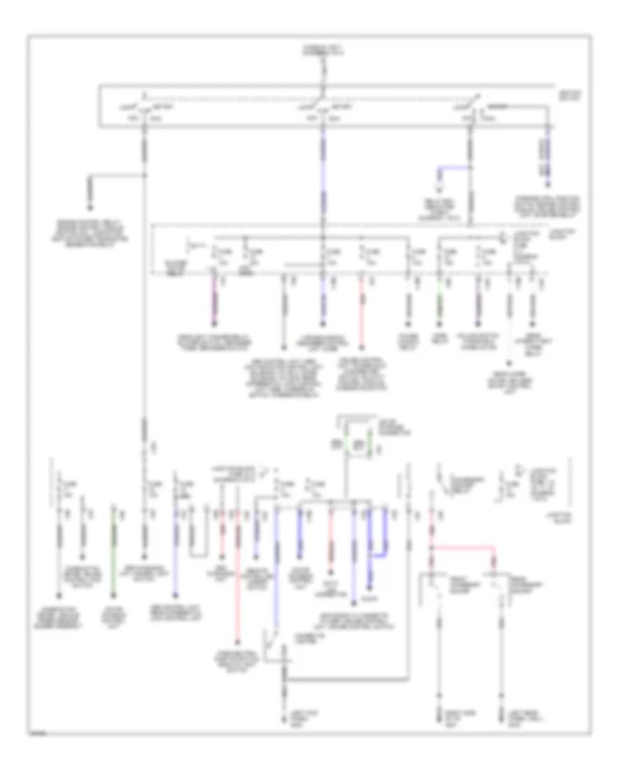
Power Distribution Wiring Diagram (1 of 2) for Mitsubishi Montero SR 1996
List of elements for Power Distribution Wiring Diagram (1 of 2) for Mitsubishi Montero SR 1996:
- (not used)
- Air conditioning compressor clutch
- Am/fm radio w/ cassette player, spare connector for cd audio changer, ignition keyhole illumination light timer
- Battery
- Blower motor relay
- C100
- C78
- C79
- C81
- C83
- C93
- C94
- C96
- C97
- Cargo space light, reading light, dome light
- Clock, multi meter, left front door light, right front door light, keyless entry control unit, elc-4a/t control module, buzzer assembly, cruise control unit, abs control unit
- Combination meter (beam)
- Condenser fan motor
- Data link connector
- Dedicated fuse (relay box)
- Dedicated fuses (relay box)
- Defogger relay
- Door lock control unit
- Door lock relay
- Door lock relay, combination meter
- Engine control module
- Engine control relay
- Fuse 10a
- Fuse 15a
- Fuse 20a
- Fuse 25a
- Fusible link
- Fusible link 1 60a
- Fusible link 10 30a
- Fusible link 12 30a
- Fusible link 13 40a
- Fusible link 4 60a
- Fusible link 5 100a
- Fusible link 6 20a
- Fusible link 7 40a
- Fusible link 9 30a
- Generator
- Hazard light switch
- Headlight relay
- Headlight washer motor
- Horn relay
- Hydraulic unit
- Ignition switch (diagram 2 of 2)
- Iod or storage connector
- J/c 3 (left side of i/p)
- Junction block
- Junction c block fuse 14 (diagram 2 of 2)
- Left headlight, right headlight
- Left rear combination light, left front combination light, right front combination light, clock, headlight washer relay, right rear combination light, left license plate lamp, right license plate lamp, shock absorber control switch, rheostat, combination meter, power window main switch, left vanity mirror light, right vanity mirror light, ashtray illumination light, cigarette lighter illumination light, rear differential lock switch, heater control illumination light, power/hold changeover switch, hazard light switch, multi meter am/fm radio w/ cassette player, buzzer assembly, defogger switch, overdrive switch, cruise control main switch, diode
- Motor antenna control unit
- Nca
- Power window relay, power seat assembly
- Red
- Starter motor
- Stop light switch
- Sunroof switch
- Tail light relay
Power Distribution Wiring Diagram (2 of 2) for Mitsubishi Montero SR 1996
List of elements for Power Distribution Wiring Diagram (2 of 2) for Mitsubishi Montero SR 1996:
- (a/t) (m/t)
- (diagram 2 of 2)
- (left kick panel) g200
- (left rear wheel well) g402
- (not used)
- (right side of i/p) g201
- Abs control unit (1996), 4wd indicator control unit, solenoid valve a, diode, solenoid valve b, rear differential lock control unit (1996), overdrive switch, overdrive relay
- Abs control unit, rear differential lock control unit
- Acc
- Accessory socket relay
- Am/fm radio w/ cassette player, cruise control unit, cruise control switch
- Blower motor relay
- C100
- C101
- C80
- C81
- C93
- C94
- C95
- C96
- C97
- C98
- Cigarette lighter
- Clock
- Column switch, windshield wiper motor
- Combination meter, cruise control main switch
- Combination meter, vehicle speed sensor, buzzer assembly
- Cruise control unit, power/hold changeover switch, elc-4a/t control module, overdrive switch
- Data link connector
- Engine control relay, engine control module ignition coil, capacitor, ignition power transistor, generator relay
- Front accessory socket
- Fuse 10a
- Fuse 15a
- Fusible link 7 (diagram 1 of 2)
- Headlight washer relay, blower switch, defogger timer, defogger switch
- Horn relay
- Ignition switch
- Iod or storage connector
- Junction block
- Junction block fuse 1, 6, 16, 17, 19 (diagram 1 of 2)
- Junction block fuse 10, 9 d
- Junction block fuse 5, 4 (diagram 2 of 2)
- Lock
- Motor antenna control unit
- Park/neutral position switch, back-up light switch
- Park/neutral position switch, engine control module, cruise control unit, starter relay
- Pnk
- Power window relay
- Rear accessory socket
- Rear intermittent
- Rear wiper motor, keyless entry control unit
- Red
- Relay
- Relay box dedicated fuse 9 (diagram 1 of 2)
- Remote controlled mirror switch
- Run
- Srs diagnosis unit
- Srs diagnosis unit, hazard light switch
- Start
- Variable shock absorber control unit, diode
- Wiper
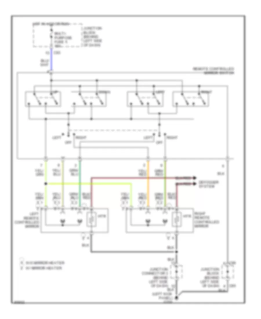
POWER MIRRORS
Power Mirror Wiring Diagram for Mitsubishi Montero SR 1996
List of elements for Power Mirror Wiring Diagram for Mitsubishi Montero SR 1996:
- (left kick panel) g200
- C93
- C95
- C96
- Defogger system
- Down
- Hot in acc or run
- Htr
- Junction block (behind left side of dash)
- Junction connector 3 (behind left side of dash)
- Left
- Left remote controlled mirror
- Multi- purpose fuse 5 15a
- Off
- Remote controlled mirror switch
- Right
- Right remote controlled mirror
- W/ mirror heater
- W/o mirror heater
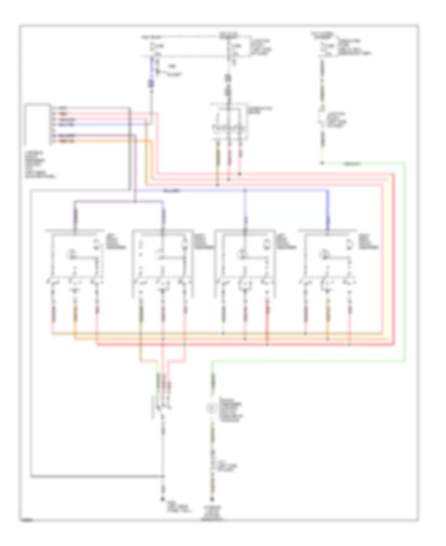
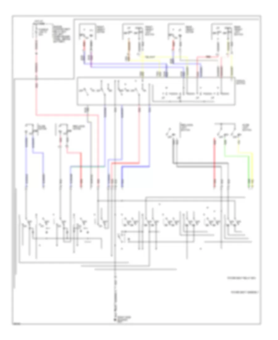
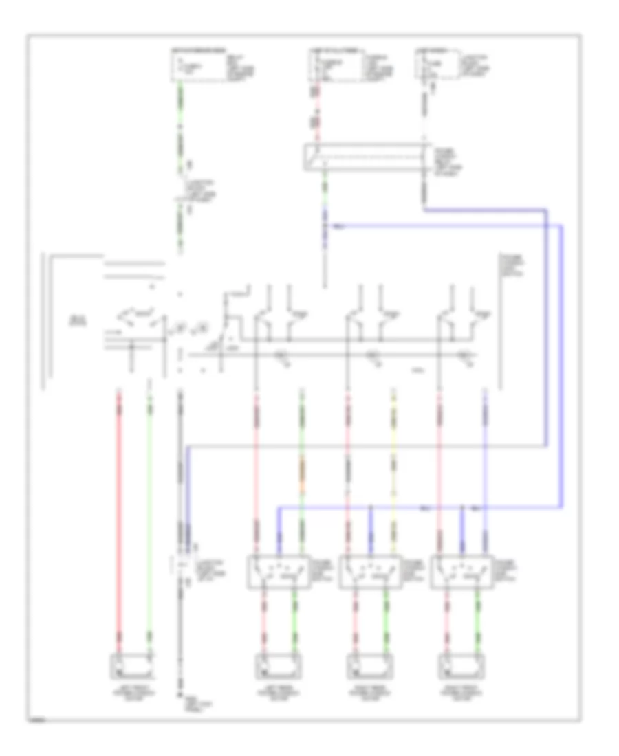
POWER SEATS
Power Seat Wiring Diagrams for Mitsubishi Montero SR 1996
List of elements for Power Seat Wiring Diagrams for Mitsubishi Montero SR 1996:
- (right side of dash) g201
- Down
- Engine compartment relay box (on left inner fender panel, behind battery)
- Front height limit switch
- Front height motor
- Fusible link 10 30a
- Hot at all times
- Manual switch
- Off
- Power seat assembly
- Power seat relay box
- Rear height limit switch
- Rear height motor
- Reclining limit switch
- Reclining motor
- Red
- Slide limit switch
- Slide motor
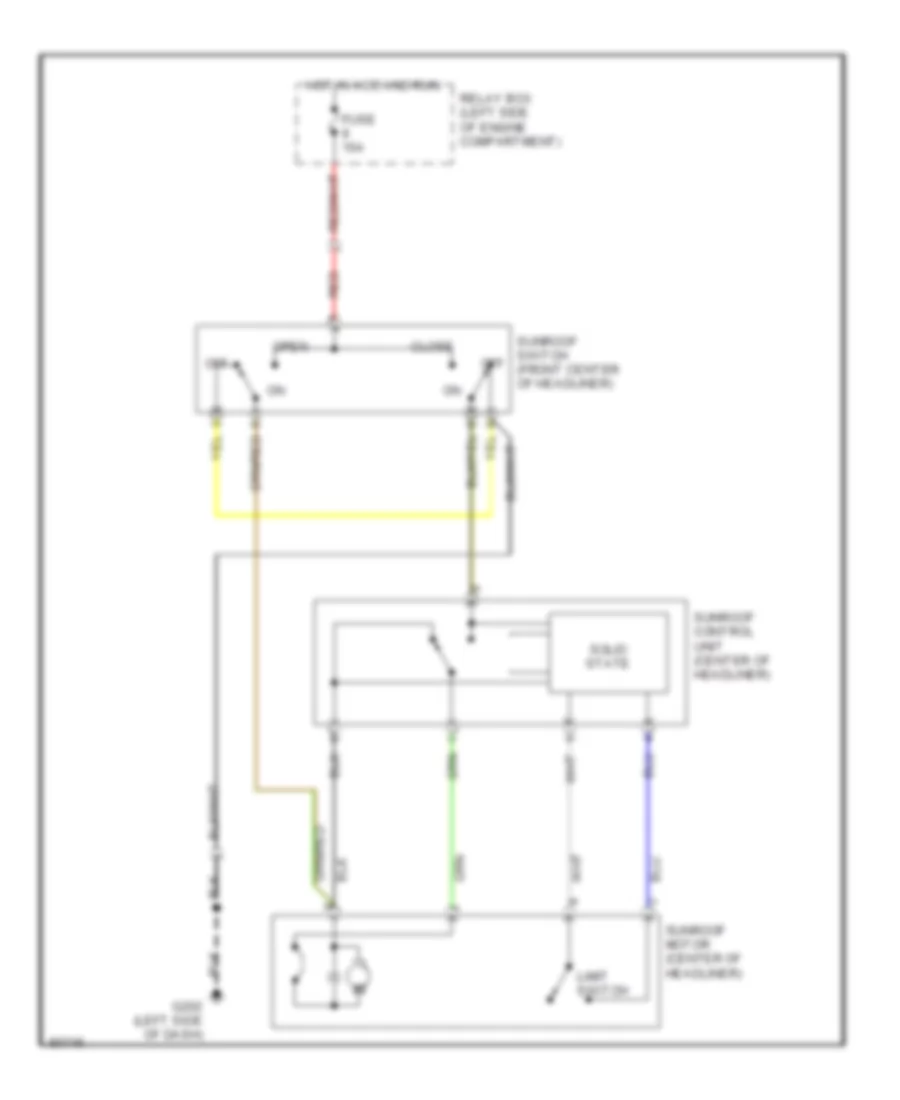
POWER TOP/SUNROOF
Power Top/Sunroof Wiring Diagrams for Mitsubishi Montero SR 1996
List of elements for Power Top/Sunroof Wiring Diagrams for Mitsubishi Montero SR 1996:
- Close
- Fuse 15a
- G202 (left side of dash)
- Hot in acc and run
- Limit switch
- Off
- Open
- Red
- Relay box (left side of engine compartment)
- Solid state
- Sunroof control unit (center of headliner)
- Sunroof motor (center of headliner)
- Sunroof switch (front center of headliner)
POWER WINDOWS
Power Window Wiring Diagram for Mitsubishi Montero SR 1996
List of elements for Power Window Wiring Diagram for Mitsubishi Montero SR 1996:
- C100
- C80
- C94
- C95
- C97
- Down
- Fuse 10a
- Fuse 5 10a
- Fusible link (left side of engine compt)
- Fusible link 30a
- G200 (left kick panel)
- Hot at all times
- Hot in park or head
- Hot in run
- Junction block (left side of dash)
- Junction block (left side of i/p)
- Left front power window motor
- Left rear power window motor
- Lock
- Power window main switch
- Power window relay (left side of dash)
- Power window sub switch
- Red
- Relay box (left side of engine compt)
- Right front power window motor
- Right rear power window motor
- Solid state
- Un lock
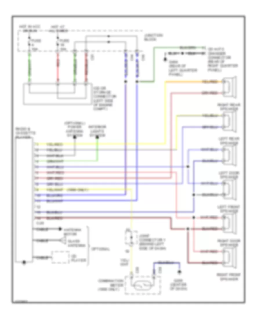
RADIO
Radio Wiring Diagrams for Mitsubishi Montero SR 1996
List of elements for Radio Wiring Diagrams for Mitsubishi Montero SR 1996:
- (1996 only)
- (optional) power antenna system
- Antenna motor
- C-20
- C04
- C06
- C81
- C94
- C96
- Cable
- Cd auto changer
- Cd player
- Combination meter
- Connector (rear of right quarter panel)
- Fuse 10a
- G206 (center of dash)
- G404 (rear of left quarter panel)
- Glass antenna
- Hot at all times
- Hot in acc or run
- Interior lights system
- Iod or storage connector (left side of engine compt)
- Joint connector 1 (behind left side of dash)
- Junction block
- Left door speaker
- Left front speaker
- Left rear speaker
- Optional
- Radio & cassette player
- Red
- Right door speaker
- Right front speaker
- Right rear speaker
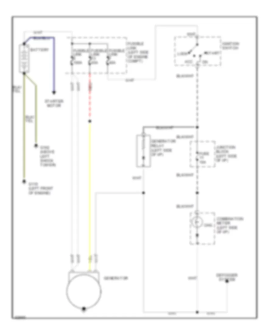
STARTING/CHARGING
Charging Wiring Diagram for Mitsubishi Montero SR 1996
List of elements for Charging Wiring Diagram for Mitsubishi Montero SR 1996:
- Acc
- Battery
- Chg
- Combination meter (left side of i/p)
- Defogger system
- Fuse 10a
- Fusible link (left side of engine compt)
- Fusible link 100a
- Fusible link 40a
- G102 (above left shock tower)
- G110 (left front of engine)
- Generator
- Generator relay (left side of i/p)
- Ignition switch
- Junction block (left side of i/p)
- Lock
- Red
- Start
- Starter motor
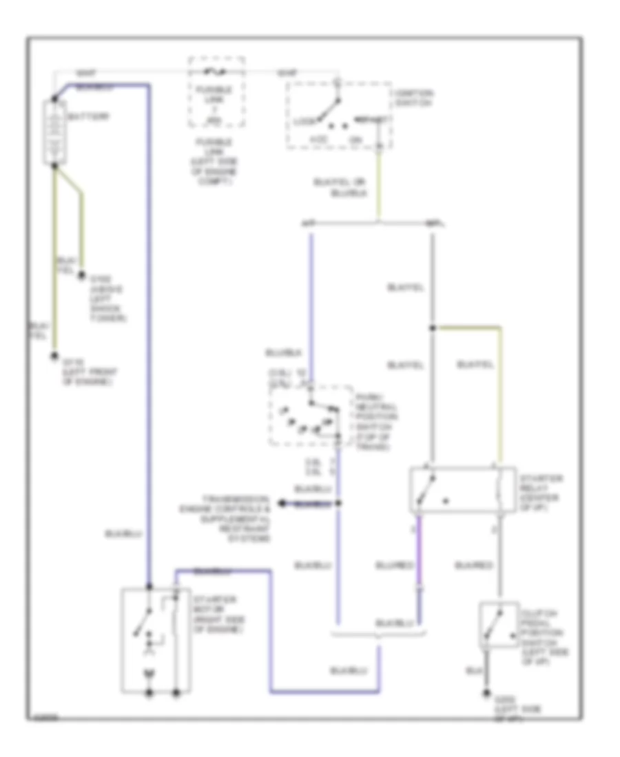
Starting Wiring Diagram for Mitsubishi Montero SR 1996
List of elements for Starting Wiring Diagram for Mitsubishi Montero SR 1996:
- (3.0l) (3.5l)
- 3.0l 3.5l
- A/t
- Acc
- Battery
- Clutch pedal position switch (left side of i/p)
- Fusible link (left side of engine compt)
- Fusible link 40a
- G102 (above left shock tower)
- G110 (left front of engine)
- G202 (left side of i/p)
- Ignition switch
- Lock
- M/t
- Park/ neutral position switch (top of trans)
- Start
- Starter motor (right side of engine)
- Starter relay (center of i/p)
SUPPLEMENTAL RESTRAINTS
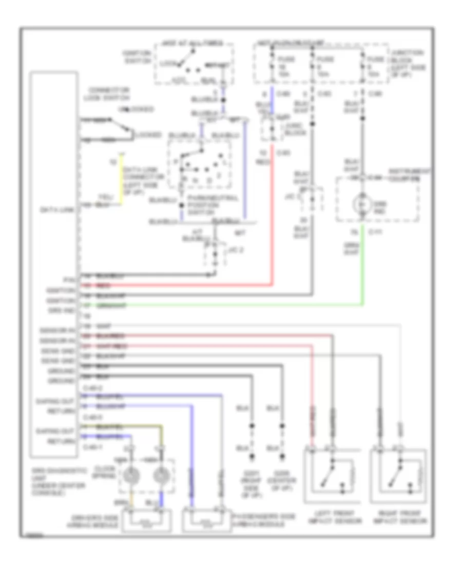
Supplemental Restraint Wiring Diagram for Mitsubishi Montero SR 1996
List of elements for Supplemental Restraint Wiring Diagram for Mitsubishi Montero SR 1996:
- (left side of i/p)
- A/t
- Acc
- C-04
- C-11
- C-40-1
- C-40-2
- C-40-5
- C-80
- C-93
- C-96
- Clock spring
- Connector lock switch
- Data link
- Data link connector
- Driver's side airbag module
- Fuse 10a
- G201 (right side of i/p)
- G206 (center of i/p)
- Ground
- Hot at all times
- Hot in on or start
- Ignition
- Ignition switch
- Instrument cluster
- J/c 2
- J/c 3
- Junc. block
- Junction block (left side of i/p)
- Left front impact sensor
- Lock
- Locked
- M/t
- Nca
- P/n
- Park/neutral position switch
- Passenger's side airbag module
- Red
- Return
- Right front impact sensor
- Run
- Safing out
- Sens gnd
- Sensor in
- Srs diagnostic unit (under center console)
- Srs ind
- Srs ind.
- Start
- Unlocked
TRANSMISSION
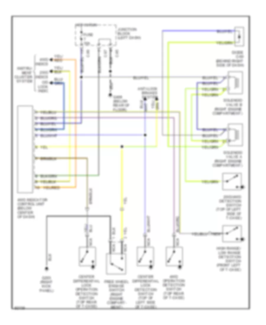
Active Trac 4WD Wiring Diagram for Mitsubishi Montero SR 1996
List of elements for Active Trac 4WD Wiring Diagram for Mitsubishi Montero SR 1996:
- 2wd indics
- 2wd/4wd detection switch (top of left side of t-case)
- 4wd indicator control unit (below center of dash)
- 4wd indics
- 4wd operation detection switch (top rear of t-case)
- Anti-lock brakes system
- C-95
- C-96
- C-97
- C/d lock indic
- Center differential lock detection switch (top of left side of t-case)
- Center differential lock operation detection switch (top rear of t-case)
- Diode c-60 (behind right side of dash)
- Free wheel engage switch (right engine compart- ment)
- Fuse 10a
- G203 (right kick panel)
- G409 (below rear of floor)
- High range/ low range detection switch (front left of t-case)
- Hot in run
- Instru- ment cluster system
- Junction block (left dash)
- Nca
- Solenoid valve a (right engine compartment)
- Solenoid valve b (right engine compartment)
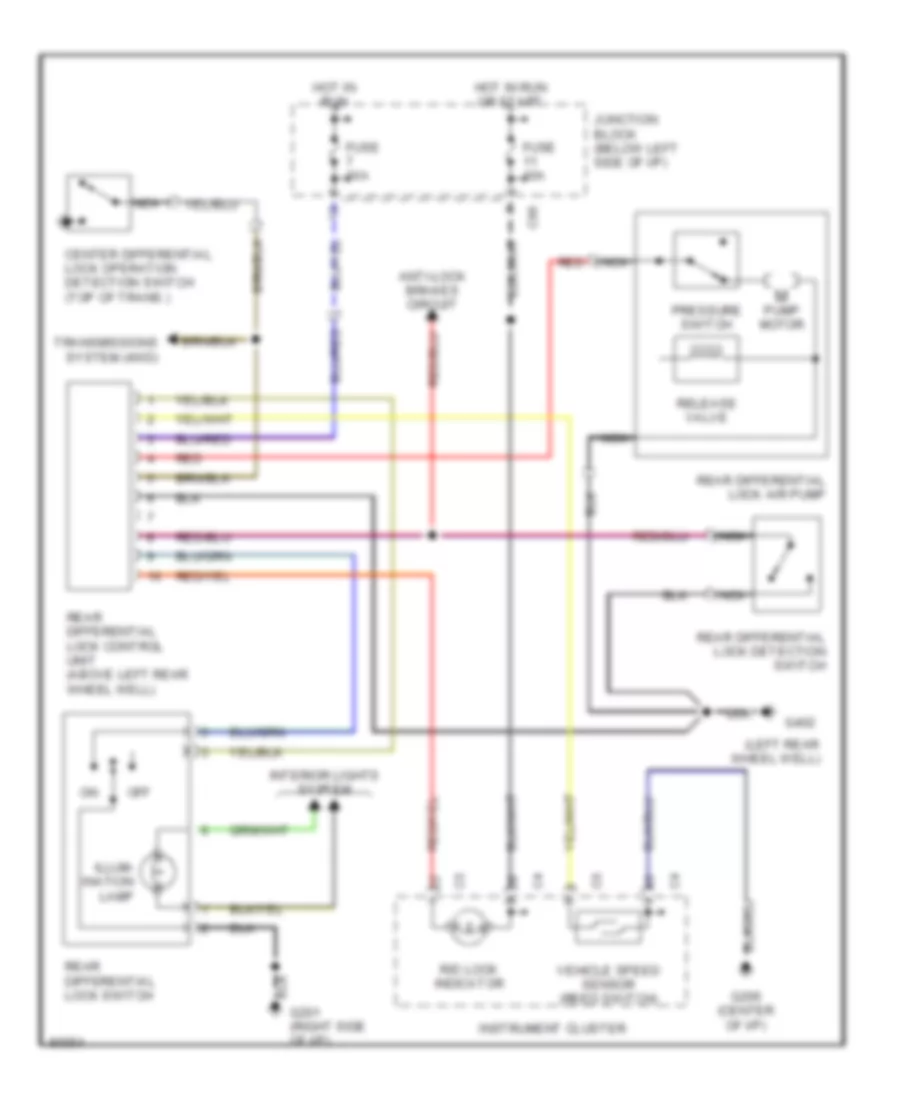
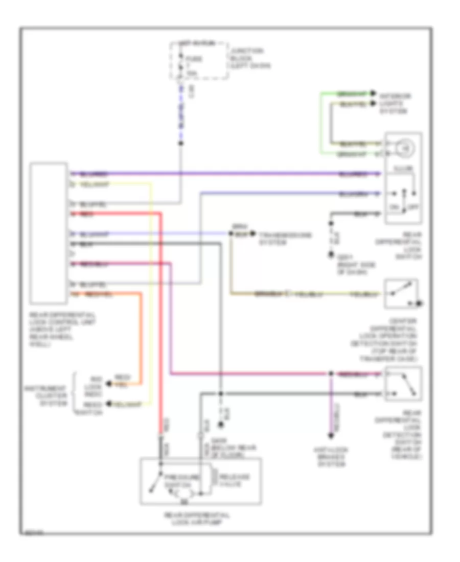
Rear Differential Lock Wiring Diagram for Mitsubishi Montero SR 1996
List of elements for Rear Differential Lock Wiring Diagram for Mitsubishi Montero SR 1996:
- Anti-lock brakes system
- C-96
- Center differential lock operation detection switch (top rear of transfer case)
- Fuse 10a
- G201 (right side of dash)
- G409 (below rear of floor)
- Hot in run
- Illum.
- Instrument cluster system
- Interior lights system
- Junction block (left dash)
- Nca
- Off
- Pressure switch
- R/d lock indic
- Rear differential lock air pump
- Rear differential lock control unit (above left rear wheel well)
- Rear differential lock detection switch (rear of vehicle)
- Rear differential lock switch
- Red
- Reed switch
- Release valve
- Transmissions system
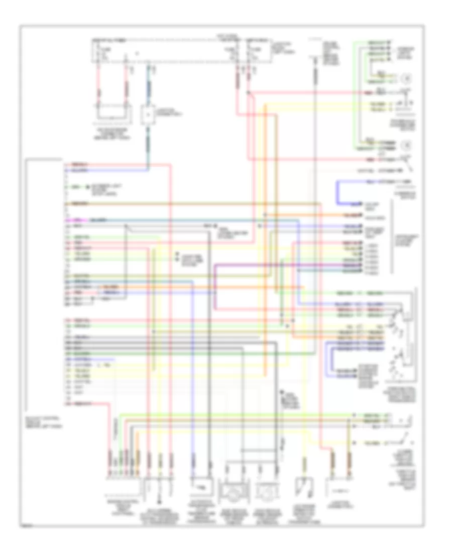
Transmission Wiring Diagram for Mitsubishi Montero SR 1996
List of elements for Transmission Wiring Diagram for Mitsubishi Montero SR 1996:
- 2 indic
- Automatic transmission fluid temperature sensor (transmission)
- C-81
- C-93
- C-96
- C-97
- Closed throttle position switch
- Computer data lines system
- Cruise control unit (behind center of dash)
- D indic
- Elc 4-speed auto transmission control solenoids (in transmission)
- Elc-4a/t control module (behind left dash)
- Engine control module (right kick panel)
- Exterior light system (stop lamps)
- Fuse 10a
- Fuse 5a
- G206 (lower center of dash)
- Hold indic
- Hot at all times
- Hot in run
- Illum.
- Instrument cluster system
- Interior lights system
- Iod or storage connector (behind left dash)
- Junction block (left dash)
- Junction connector 2
- Junction connector 3
- L indic
- Low range operation detection switch (transfer case)
- Main vehicle speed sensor (tailshaft extension)
- N indic
- Nca
- O/d off indic
- Off
- Or start
- Overdrive switch
- P indic
- P r
- Park/neutral position switch (right side of transmission)
- Power/hold changeover switch
- Pwr indic a/t temp indic
- R indic
- Red
- Starting/ charging system & engine controls system
- Sub vehicle speed sensor (on trans- mission)
- Throttle position sensor (on throttle body)
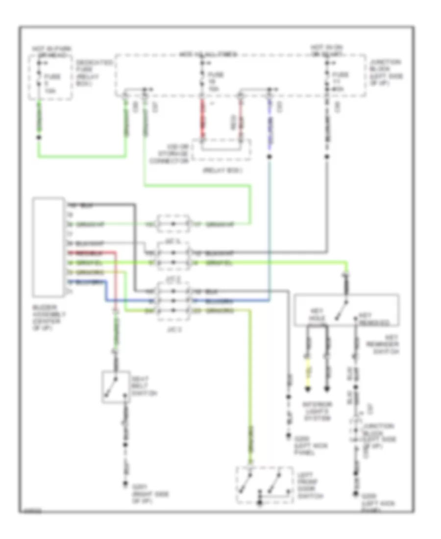
WARNING SYSTEMS
Warning System Wiring Diagrams for Mitsubishi Montero SR 1996
List of elements for Warning System Wiring Diagrams for Mitsubishi Montero SR 1996:
- (relay box)
- Buzzer assembly (center of i/p)
- C80
- C81
- C93
- C95
- C96
- C97
- C97 junction block (left side of i/p)
- Dedicated fuse (relay box)
- Fuse 10a
- G200 (left kick panel
- G201 (right side of i/p)
- Hot at all times
- Hot in on or start
- Hot in park or head
- Interior lights system
- Iod or storage connector
- J/c 1
- J/c 2
- J/c 3
- Junction block (left side of i/p)
- Key hole illum
- Key reminder switch
- Key removed
- Left front door switch
- Nca
- Red
- Seat belt switch
WIPER/WASHER
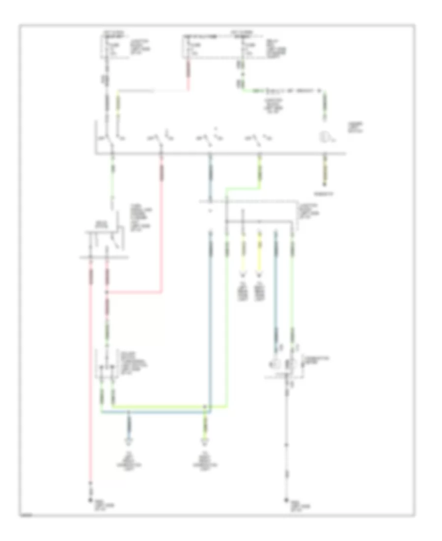
Headlamp Washer Wiring Diagram for Mitsubishi Montero SR 1996
List of elements for Headlamp Washer Wiring Diagram for Mitsubishi Montero SR 1996:
- (left front fender) g100
- C57
- C58
- C80
- Column switch
- Fuse 10a
- Headlight washer motor (right side of engine compt)
- Headlight washer relay (left side of i/p)
- Headlight washer switch
- Hot in park or head
- Hot in run
- Junction block (left side of i/p)
- Red
- Relay box (left side of engine compt)
- Solid state
Wiper/Washer Wiring Diagram for Mitsubishi Montero SR 1996
List of elements for Wiper/Washer Wiring Diagram for Mitsubishi Montero SR 1996:
- 15a
- C100
- C101
- Circuit breaker
- Column switch (left side of i/p)
- Fuse
- G100 (left front fender)
- G402 (left rear wheel well)
- G407 (center of rear door)
- Hot in acc or run
- Int
- Intermittent wiper relay
- Junction block (left side of i/p)
- Off
- Rear intermittent wiper relay (left side of i/p)
- Rear washer motor (center of rear door)
- Rear washer switch
- Rear wiper motor (center of rear door)
- Rear wiper switch
- Solid state
- Variable intermittent wiper control switch
- Wind- shield washer switch
- Wind- shield wiper switch
- Windshield washer motor (left side of engine compt)
- Windshield wiper motor (left rear of engine compt)

 Čeština
 Dansk
Dansk Deutsch
 Ελληνικά
 English
 English
 Español
 Français
 Français
 עברית
עברית Hrvatski
 Magyar
 Italiano
 日本語
日本語 한국어
한국어 Nederlands
 Polski
 Português
 Português
 Română
 Русский
 Slovenčina
 Slovenščina
 Svenska
 Türkçe
 中文 (中国)