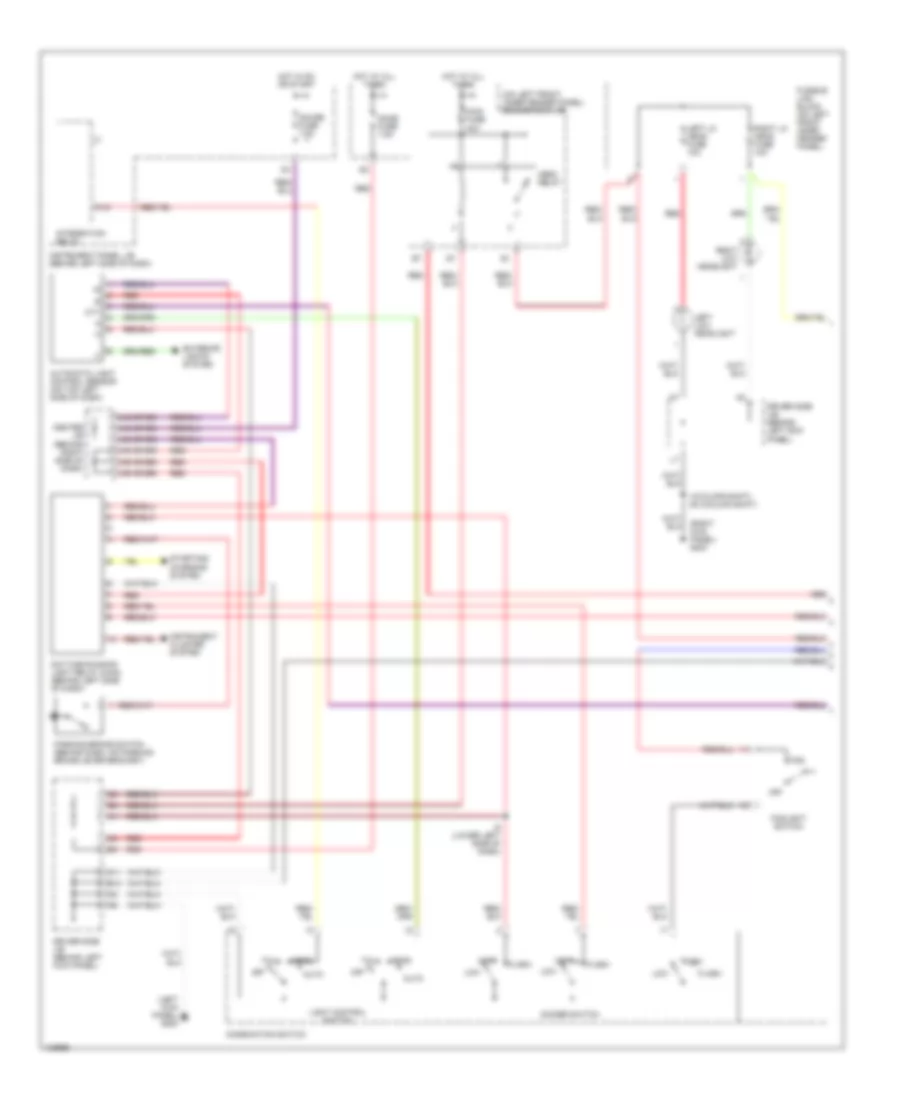
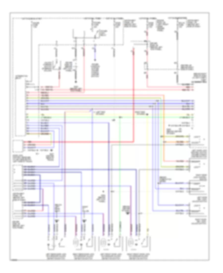
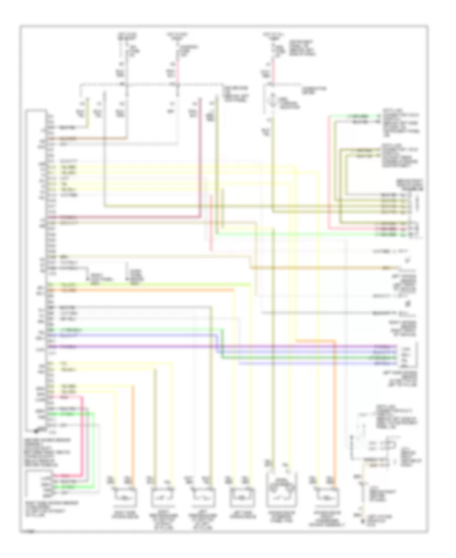
AIR CONDITIONING
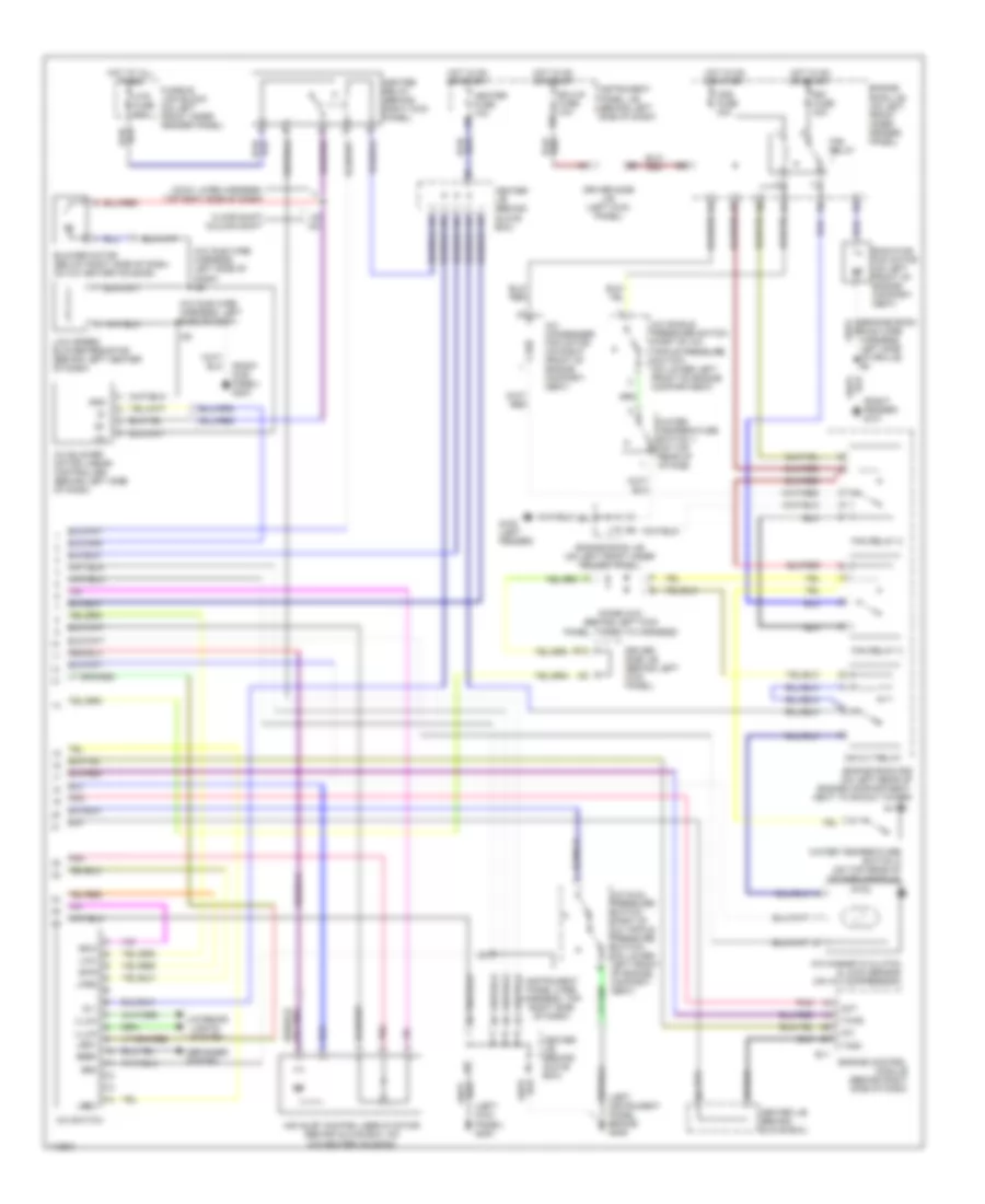
Automatic A/C Wiring Diagram (1 of 2) for Toyota Avalon XLS 1999
 https://portal-diagnostov.com/license.html
Automotive Electricians Portal FZCO
Automotive Electricians Portal FZCO
https://portal-diagnostov.com/license.html
https://portal-diagnostov.com/license.html
Automotive Electricians Portal FZCO
Automotive Electricians Portal FZCO
List of elements for Automatic A/C Wiring Diagram (1 of 2) for Toyota Avalon XLS 1999:
- (behind left center of dash) a/c room temperature sensor
- (behind right side of dash) a/c evaporator temperature sensor
- (left kick panel) g200
- (on lower right front of grille) a/c ambient temperature sensor
- (on top right side of dash) a/c solar sensor
- A/c amplifier (behind left center of dash)
- A10
- A11
- A12
- A13
- A14
- A15
- A16
- A17
- A18
- A19
- A20
- Ac1
- Act
- Aif
- Air
- Air mix control servo motor (behind left center of dash, on a/c-heater housing)
- Air vent mode control servo motor (behind left center of dash, on a/c-heater housing)
- Amc
- Amh
- Amout
- B/l
- B10
- B11
- B12
- B13
- B14
- B15
- B16
- B17
- B18
- Blw
- Bset
- C10
- C11
- C12
- C13
- C14
- C15
- C16
- C17
- C18
- C19
- C20
- C21
- C22
- Center j/b (behind glove box)
- Clock
- Control circuit
- Cool
- Dash)
- Def
- Ecu-b fuse 5a
- Engine room j/b (on left front inner fender panel)
- F/d
- Face
- Foot
- Gnd
- H14
- H15
- Heater control switch
- Hot at all times
- I12 (cowl wire harness, top center of dash)
- I22 (instrument panel wire harness, top right side of dash)
- I22 (instrument panel wire harness, top right side of dash)
- Ign
- Illum
- Instrument cluster system
- Interior lights system
- L-a/c
- L-auto
- L-b/l
- L-bhi
- L-blo
- L-bm1
- L-bm2
- L-def
- L-face
- L-foot
- L-frs
- L-rec
- Laut
- Lb/l
- Lbhi
- Lblo
- Lbm1
- Lbm2
- Ldef
- Led+
- Lfot
- Lockin
- Lvnt
- Maut
- Mgc
- Motor position switches
- Mset
- Off
- Pnk
- Psw
- S-a/c
- S-def
- S-mauto
- S-off
- S-r/f
- Speed
- Tam
- Tpi
- Tset
- Vent
- Ver
- Warm
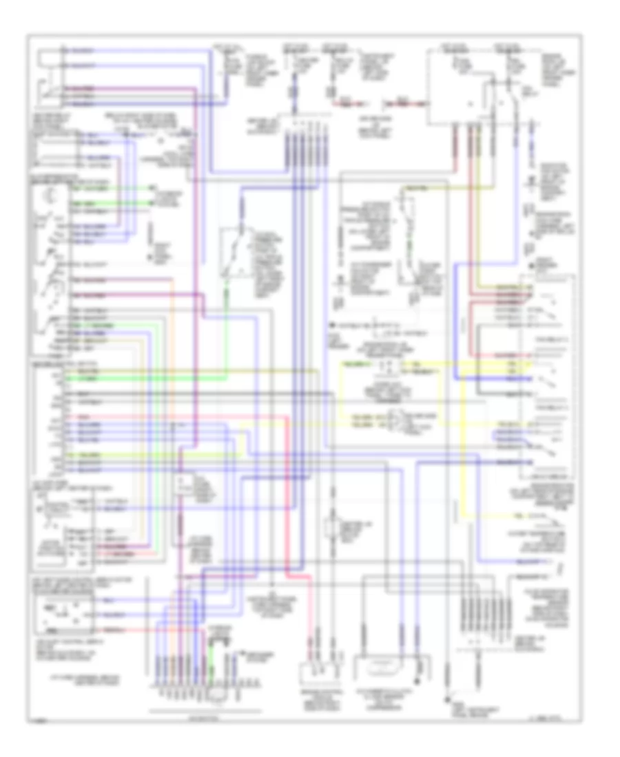
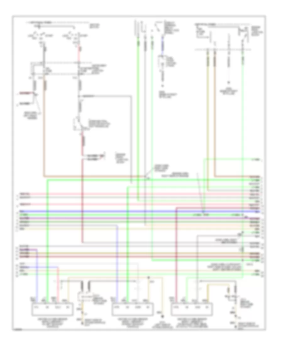
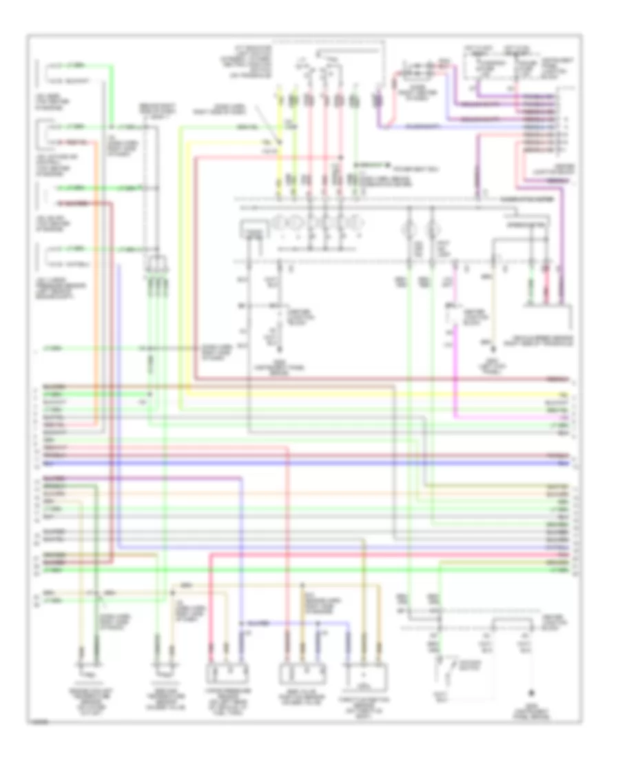
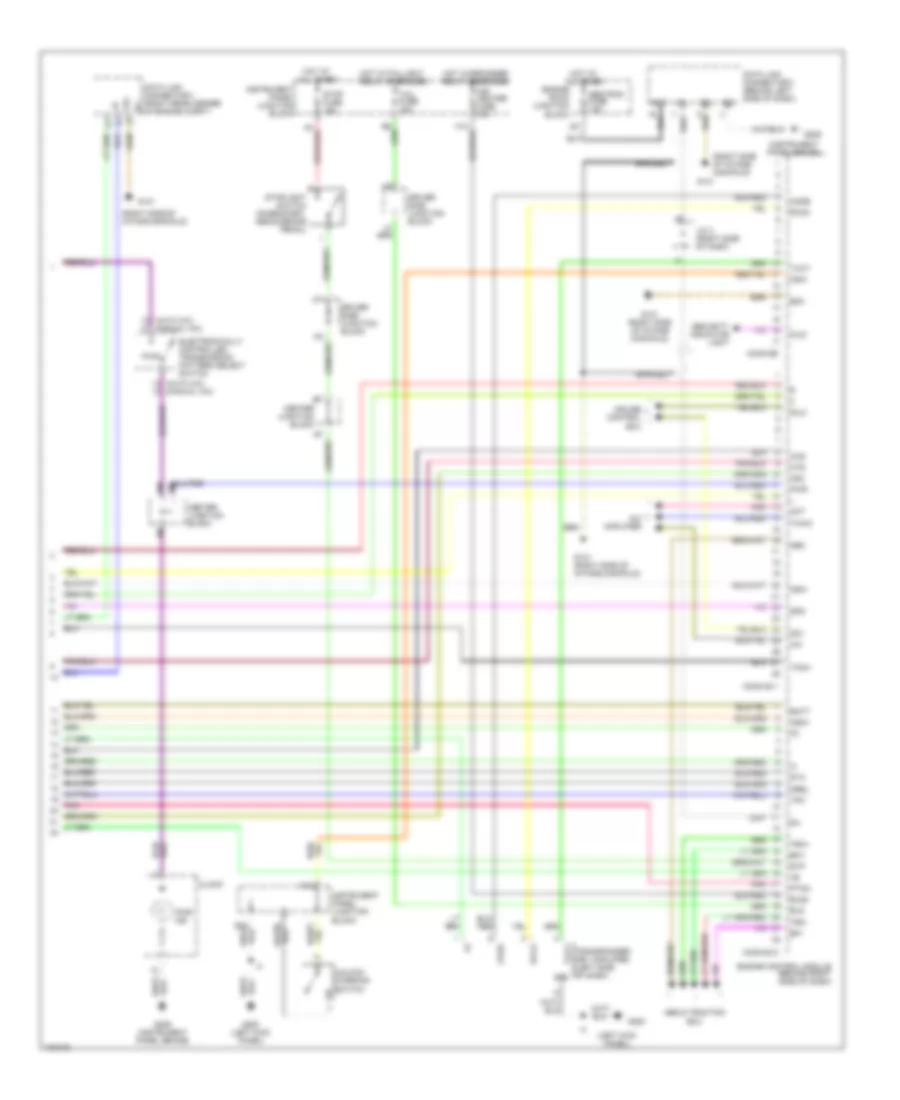
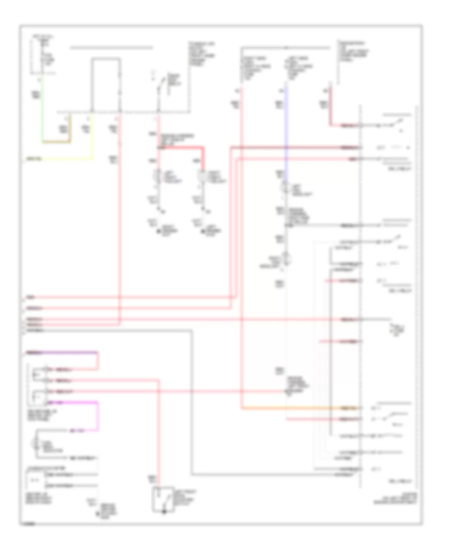
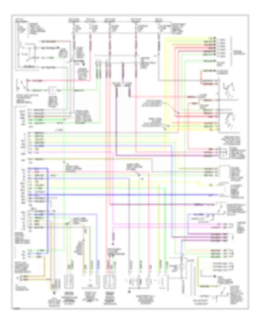
Automatic A/C Wiring Diagram (2 of 2) for Toyota Avalon XLS 1999
List of elements for Automatic A/C Wiring Diagram (2 of 2) for Toyota Avalon XLS 1999:
- (a/c sub wire harness, left side of dash)
- (a/c sub wire harness, left side of dash) i28
- (cowl wire harness, top rght side of dash)
- (instrument panel wire harness, top right side of dash)
- (left instrument panel brace) g206
- (left kick panel) g200
- (right fender) g101
- A/c
- A/c blower motor linear controller (behind left side of dash)
- A/c condenser fan motor (on right front of engine compart- ment)
- A/c dual pressure switch (part of a/c triple pressure switch) (on lower left front of engine compart- ment)
- A/c magnetic clutch & lock sensor (on a/c compressor)
- A/c single pressure switch (part of a/c triple pressure switch) (on lower left front of engine compartment)
- A/c switch
- Act
- Air inlet control servo motor (behind glove box, on a/c-heater housing)
- B12
- Blower motor (below right side of dash, on a/c heater housing)
- Cds fuse 30a
- Center j/b (behind glove box)
- Defogger system
- Diode (a/c) (behind left kick panel, taped to harness)
- Driver side j/b (behind left kick panel)
- Driver side j/b (left kick panel)
- E11
- Ecu-ig fuse 10a
- Engine control module (behind right side of dash)
- Engine room j/b (on left front inner fender panel)
- Engine room r/b (on left rear of engine compartment, next to shock tower)
- Fan relay
- Fan relay 2
- Fan relay 3
- Floor shift column shift
- Fusible link block (on left front inner fender panel)
- G100 (left fender)
- Gnd
- Heater fuse 10a
- Heater relay (behind right kick panel)
- Hot at all times
- Hot in on or start
- Htr fuse 50a
- I19
- I22
- I28
- Ig +
- Illum
- Instrument panel j/b (behind left side of dash)
- Interior lights system
- La/c
- Led+
- Lfrs
- Low speed blower resistor (behind left center of dash)
- Lrec
- Main wire harness, left side of grille) e4
- Mg clt relay
- Pnk
- Radiator fan motor (on left front of engine compart- ment)
- Rdef
- Rdi fuse 30a
- Sa/c
- Sf/r
- Tach
- Twho
- Water temperature switch 1 (on top rear of intake)
- Water temperature switch 2 (on top rear of intake manifold)
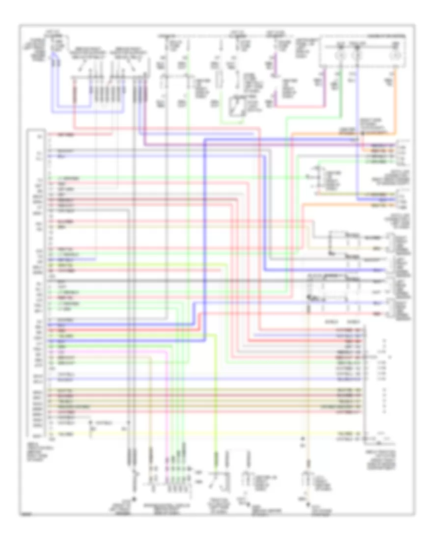
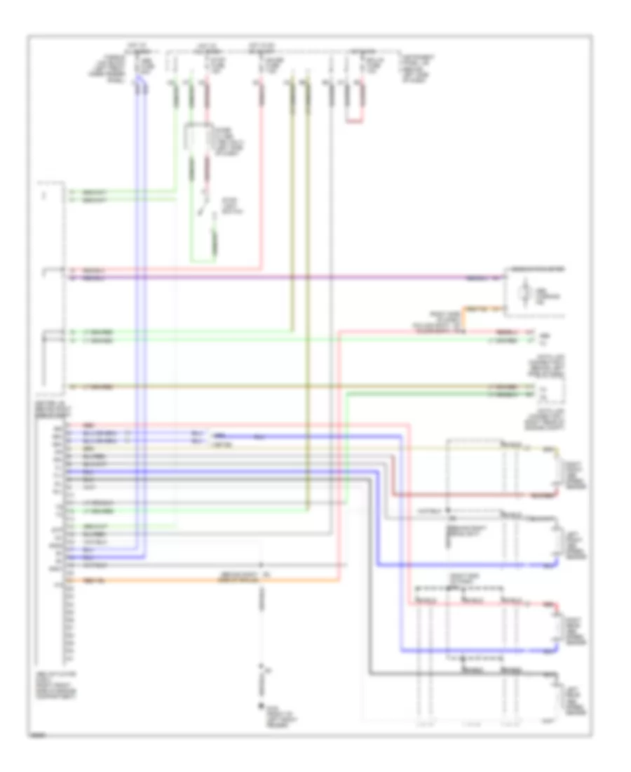
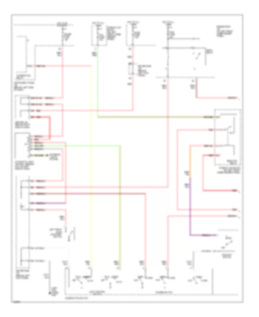
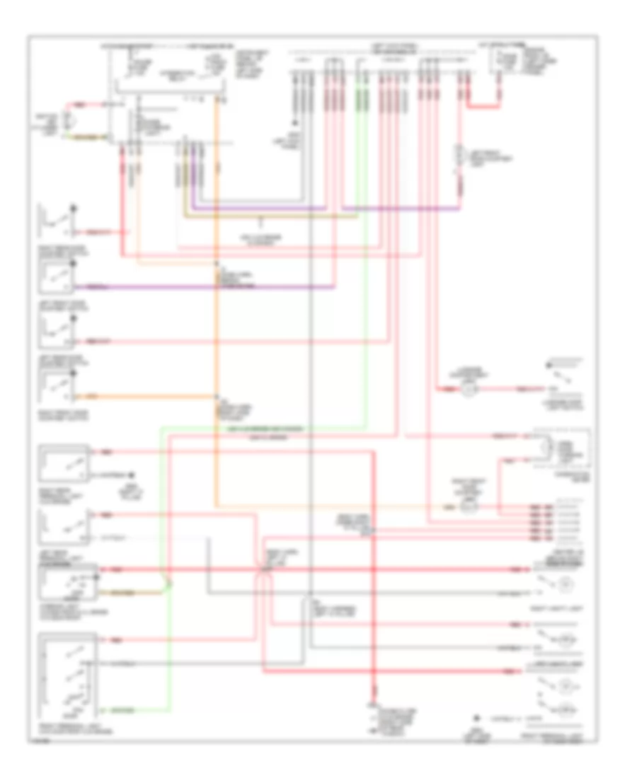
Manual A/C Wiring Diagram for Toyota Avalon XLS 1999
List of elements for Manual A/C Wiring Diagram for Toyota Avalon XLS 1999:
- (cowl wire harness, top right side of dash)
- (engine room main wire harness, left side of grille) e4
- (i/p wire harness, behind center of dash)
- (right fender) g101
- (right kick panel) g203
- 10a
- 1995 vftc c
- A/c
- A/c amplifier (behind left center of dash)
- A/c condenser fan motor (on right front of engine compartment)
- A/c dual pressure switch (part of a/c triple pressure switch) (on lower left front of engine compart- ment)
- A/c evaporator temperature sensor (behind right side of dash, on evaporator housing)
- A/c fuse (right side of dash)
- A/c magnetic clutch & lock sensor (on a/c compressor)
- A/c single pressure switch (part of a/c triple pressure switch) (on lower left front of engine compartment)
- A/c switch
- Ac1
- Act
- Air inlet control servo motor (behind glove box, on a/c-heater housing)
- Air vent mode control servo motor (behind left center of dash, on a/c-heater housing)
- B/l
- B12
- Blower resistor (behind left center of dash)
- Cds fuse 30a
- Center j/b (behind glove box)
- Control circuit
- D13
- D25
- D27
- Def
- Defogger system
- Diode (a/c) (behind left kick panel, taped to harness)
- Driver side j/b (behind left kick panel)
- Driver side j/b (left kick panel)
- E11
- Ecu-ig fuse 10a
- Engine control module (behind right side of dash)
- Engine room j/b (on left front inner fender panel)
- Engine room r/b (on left rear of engine compartment, next to shock tower)
- F/d
- Face
- Fan relay
- Fan relay 2
- Fan relay 3
- Foot
- Frs
- Fusible link block (on left front inner fender panel)
- G100 (left fender)
- G206 (left instrument panel brace)
- Gnd
- Ha/c
- Heater control switch
- Heater fuse 10a
- Heater relay (behind right kick panel)
- Hot at all times
- Hot in on
- Hot in on or start
- Htr fuse 50a
- I14
- I19 or i20
- I22 (instrument panel wire harness, top right side of dash)
- Ig+
- Ign
- Instrument panel j/b (behind left side of dash)
- Interior lights system
- L-a/c
- La/c
- Lock
- Mg clt relay
- Mgc
- Motor position switches
- Off
- Or start
- Pnk
- Radiator fan motor (on left front of engine compart- ment)
- Rdef
- Rdi fuse 30a
- Rec
- S-a/c
- Sa/c
- Sfrs
- Srec
- Tach
- Vent
- Water temp switch 1 (on top rear of intake)
- Water temperature switch 2 (on top rear of intake manifold)
ANTI-LOCK BRAKES
Anti-lock Brake Wiring Diagrams, with Traction Control for Toyota Avalon XLS 1999
List of elements for Anti-lock Brake Wiring Diagrams, with Traction Control for Toyota Avalon XLS 1999:
- (behind right radiator support)
- (center of dash)
- (right side of dash) i19 (flr shft) i20 (clmn shft)
- A10
- A11
- A12
- A19
- A25
- A26
- A27
- A28
- A32
- A33
- A34
- Abs
- Abs & traction actuator (front right side of engine compartment)
- Abs & traction ecu (behind right side of dash)
- Abs fuse 60a
- Abs ind
- Abs motor relay
- Abs sol relay
- Ast
- C10
- Center j/b (right side of dash)
- Combination meter
- Csw
- D/g
- Data link connector 1 (right rear corner of engine compt)
- Data link connector 2 (left side of dash)
- E11
- E12
- Ecu-ig fuse 10a
- Efi+
- Efi-
- Engine control module (behind right side of dash)
- Fl+
- Fl-
- Fr+
- Fr-
- Fusible link block (left front inner fender panel)
- G100 (front of left front fender)
- G131 (on intake manifold)
- G206 (behind center of dash)
- Gauge fuse 7.5a
- Gnd1
- Gnd2
- Gnd3
- Hot at all times
- Hot in on
- Hot in on or start
- I12
- I26
- Ig1
- Ind
- Instrument panel j/b (left side of dash)
- J/c 4 (right center of dash)
- Left front abs speed sensor
- Left rear abs speed sensor
- Neo
- Noise filter (1997 0nly) (left side of dash)
- Red
- Right front abs speed sensor
- Right rear abs speed sensor
- Rl+
- Rl-
- Rr+
- Rr-
- Sflh
- Sflr
- Sfrh
- Sfrr
- Shield
- Slip ind
- Smc1
- Smc2
- Src1
- Src2
- Srlh
- Srlr
- Srrh
- Srrr
- Stop fuse 15a
- Stop- light switch
- Stp
- Trac off ind
- Traction cut switch (left side of dash)
- Trc
- Trc+
- Trc-
Anti-lock Brake Wiring Diagrams, without Traction Control for Toyota Avalon XLS 1999
List of elements for Anti-lock Brake Wiring Diagrams, without Traction Control for Toyota Avalon XLS 1999:
- (1997-98)
- (1999)
- (behind right headlight)
- (column shft) (floor shft)
- (right end of dash) i26
- (right side of dash) i20 i19
- Abs
- Abs actuator & ecu (right front side of engine compartment)
- Abs fuse 60a
- Abs warning ind
- Center j/b (behind right side of dash)
- Combination meter
- Data link connector 1 (right rear of engine compt)
- Data link connector 2 (behind left side of dash)
- E3 (behind right side of grille)
- Ecu-ig fuse 10a
- Fl+
- Fl-
- Fr+
- Fr-
- Fusible link block (left front inner fender panel)
- G100 (front of left front fender)
- Gauge fuse 7.5a
- Gnd1
- Gnd2
- Hot at all times
- Hot in on
- Hot in on or start
- Ig1
- Instrument panel j/b (behind left side of dash)
- Left front abs speed sensor
- Left rear abs speed sensor
- Noise filter (1997 only) (left side of dash)
- Red
- Right front abs speed sensor
- Right rear abs speed sensor
- Rl+
- Rl-
- Rr+
- Rr-
- Shield
- Stop fuse 15a
- Stop- light switch
- Stp
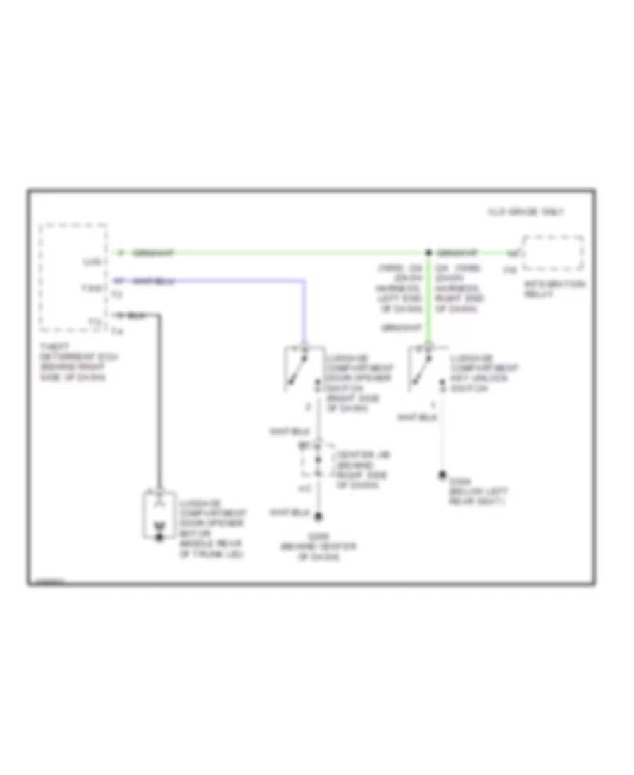
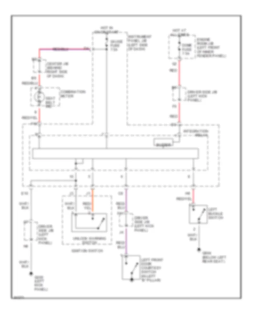
ANTI-THEFT
Forced Entry Wiring Diagram for Toyota Avalon XLS 1999
List of elements for Forced Entry Wiring Diagram for Toyota Avalon XLS 1999:
- (behind center of dash)
- (behind right kick panel) g203
- (below left rear seat) g304
- (dash harn, behind combination meter)
- (dash harn, right end of dash) i24
- (front of right front fender) g101
- +b1
- +b2
- A10
- A11
- A12
- A13
- A14
- A15
- A16
- A17
- A18
- A19
- A20
- A21
- A22
- B10
- B11
- B12
- B17
- Center j/b (behind right side of dash)
- Cty
- Dome fuse 7.5a
- Door fuse 30a
- Door locks system
- Driver side j/b (behind left kick panel)
- Dswd
- Dswh
- Dswl
- Dswp
- E (grd)
- Ecu-ig fuse 10a
- Engine hood courtesy switch
- Engine room j/b (left front inner fender panel)
- Exterior lights system
- F11
- F13
- G206
- Head
- Headlights system
- Horn
- Horn fuse 10a
- Horns system
- Hot at all times
- Hot in run or start
- I25
- I6 (dash harn, upper left end of dash)
- Immobilizer ciruit (engine control module)
- Ind
- Instrument panel j/b (behind left side of dash)
- Intergration relay
- Interior light diode
- Ksw
- Left front door courtesy switch
- Left rear door courtesy switch
- Lswd
- Lswp
- Lswr
- Lug
- Luggage compartment key unlock switch
- Luggage compartment light switch
- Red
- Right front door courtesy switch
- Right rear door courtesy switch
- Security indicator light
- Tail
- Theft deterrent ecu (behind right side of dash)
- Theft deterrent horn (on right rear of engine compt)
- Trunk, tailgate, fuel doors system
- Tsw
- Ul2
- Ul3
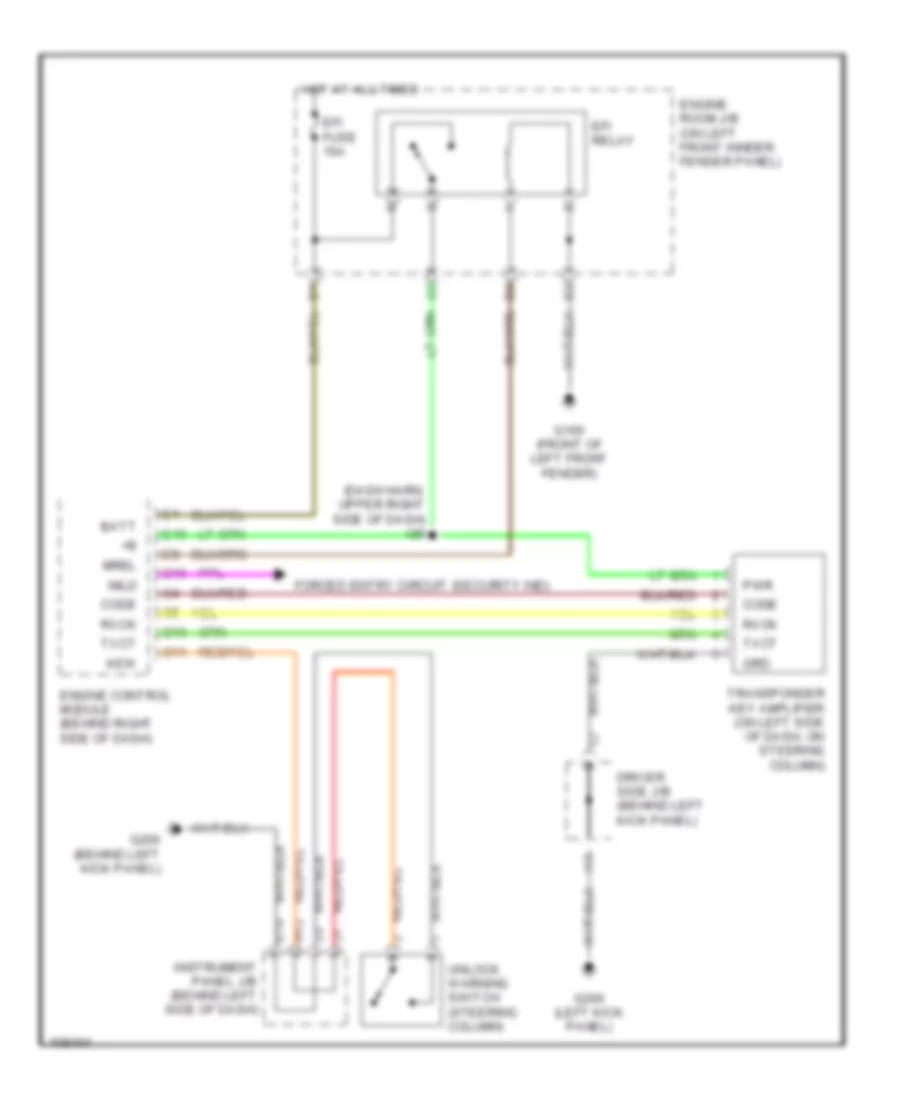
Immobilizer Wiring Diagram for Toyota Avalon XLS 1999
List of elements for Immobilizer Wiring Diagram for Toyota Avalon XLS 1999:
- (dash harn, upper right side of dash) i20
- Batt
- C10
- C11
- C16
- Code
- Driver side j/b (behind left kick panel)
- E10
- E16
- Efi fuse 15a
- Efi relay
- Engine control module (behind right side of dash)
- Engine room j/b (on left front innder fender panel)
- Forced entry circuit (security ind)
- G100 (front of left front fender)
- G200 (behind left kick panel)
- G200 (left kick panel)
- Grd
- H12
- Hot at all times
- I13
- Imld
- Instrument panel j/b (behind left side of dash)
- Ksw
- Mrel
- Pwr
- Rxck
- Transponder key amplifier (on left side of dash, on steering column)
- Txct
- Unlock warning switch (steering column)
COMPUTER DATA LINES
Computer Data Lines, with Traction Control for Toyota Avalon XLS 1999
List of elements for Computer Data Lines, with Traction Control for Toyota Avalon XLS 1999:
- (behind left side of dash) data link connector 3
- (behind right side of dash) engine control module
- (dash harn, behind right side of dash) (floor shift) i19 (column shift) i20
- (dash harn, behind right side of dash) i19 (floor shift) i20 (column shift)
- (dash harn, under top center of dash cover) i12
- 1998 except w/o engine immobilizer & 1999
- 1998 w/o engine immobilizer
- A/d
- A33
- A34
- Abs
- Abs & traction ecu (behind right side of dash)
- Abs ind
- Abs solenoid relay (right front of engine compt)
- All times
- Bat
- C16
- Center air bag sensor assembly (console shift: below rear of center console) (column shift: between front seats)
- Center j/b (behind right side of dash)
- Center j/b (right side of dash)
- Clock
- Combination meter
- Cruise control ecu (behind right side of dash)
- Cruise ind
- D/g
- Data link connector 1 (right rear of engine compt)
- Data link connector 2 (behind left side of dash)
- Driver side j/b (behind left kick panel)
- E12
- Efi relay
- Engine controls system
- Engine room j/b (on left front fender panel)
- G131 (on rear of intake manifold)
- G206 (behind center of dash)
- Gauge fuse 7.5a
- Hot at
- Hot in on
- I16 (dash harn, right side of dash)
- Instrument panel j/b (behind left side of dash)
- J/c 2 (behind center of dash)
- J/c 4 (behind right side of dash)
- Jumper wire
- Obd trac/ obd fuse 7.5a
- Or start
- Shield
- Sil
- Srs fuse 5a
- Srs ind
- Te1
- Trac off ind
- Trc
Computer Data Lines, without Traction Control for Toyota Avalon XLS 1999
List of elements for Computer Data Lines, without Traction Control for Toyota Avalon XLS 1999:
- (behind left side of dash) data link connector 3
- (behind right side of dash) engine control module
- (dash harn, behind right side of dash) (floor shift) i19 (column shift) i20
- (dash harn, behind right side of dash) i19 (floor shift) i20 (column shift)
- 1998 except w/o engine immobilizer & 1999
- 1998 w/o engine immobilizer
- A/d
- Abs
- Abs actuator & ecu (right front of engine compt)
- Abs ind
- All times
- Bat
- C16
- Center air bag sensor assembly (console shift: below rear of center console) (column shift: between front seats)
- Center j/b (behind right side of dash)
- Center j/b (right side of dash)
- Clock
- Combination meter
- Cruise control ecu (behind right side of dash)
- Cruise ind
- Data link connector 1 (right rear of engine compt)
- Data link connector 2 (behind left side of dash)
- Driver side j/b (behind left kick panel)
- E12
- Efi relay
- Engine controls system
- Engine room j/b (on left front fender panel)
- G131 (on rear of intake manifold)
- G206 (behind center of dash)
- Gauge fuse 7.5a
- Hot at
- Hot in on
- I16 (dash harn, right side of dash)
- Instrument panel j/b (behind left side of dash)
- J/c 2 (behind center of dash)
- J/c 4 (behind right side of dash)
- Obd trac/ obd fuse 7.5a
- Or start
- Shield
- Sil
- Srs fuse 5a
- Srs ind
- Te1
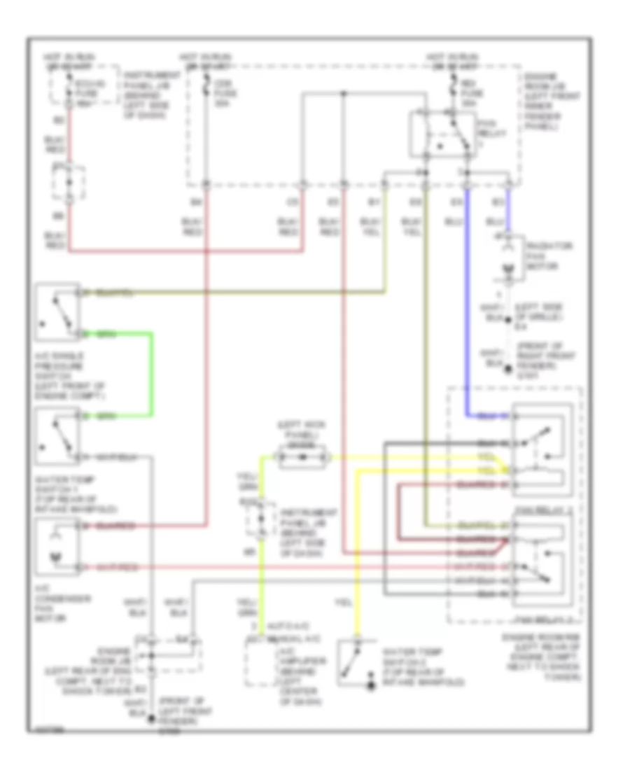
COOLING FAN
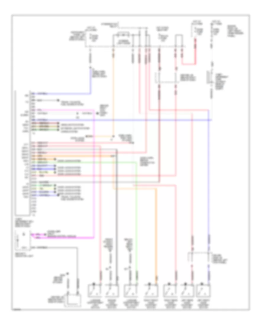
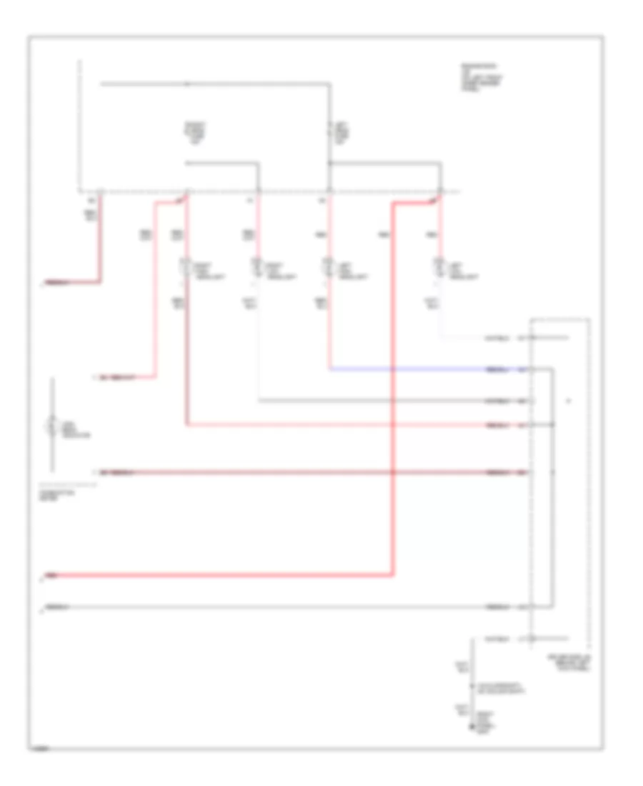
Cooling Fan Wiring Diagram for Toyota Avalon XLS 1999
List of elements for Cooling Fan Wiring Diagram for Toyota Avalon XLS 1999:
- (front of left front fender) g100
- (front of right front fender) g101
- (left kick panel) diode
- (left side of grille) e4
- A/c amplifier (behind left center of dash)
- A/c condenser fan motor
- A/c single pressure switch (left front of engine compt)
- Auto a/c
- B12
- Cds fuse 30a
- Ecu-ig fuse 10a
- Engine room j/b (left front inner fender panel)
- Engine room j/b (left rear of eng compt, next to shock tower)
- Engine room r/b (left rear of engine compt, next to shock tower)
- Fan relay
- Fan relay 2
- Fan relay 3
- Hot in run
- Hot in run or start
- Instrument panel j/b (behind left side of dash)
- Manual a/c
- Or start
- Radiator fan motor
- Rdi fuse 30a
- Water temp switch 1 (top rear of intake manifold)
- Water temp switch 2 (top rear of intake manifold)
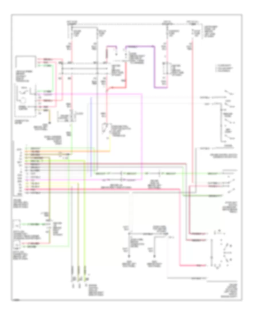
CRUISE CONTROL
Cruise Control Wiring Diagram for Toyota Avalon XLS 1999
List of elements for Cruise Control Wiring Diagram for Toyota Avalon XLS 1999:
- (dash harn, top center of dash) i12
- (dash harness, behind right side of dash)
- A/d
- As as
- Bs bs
- California
- Cancel
- Ccs
- Center j/b (behind right side of dash)
- Cig/radio fuse 15a
- Clock
- Cms
- Column shift
- Combination meter
- Cruise control actuator (left front side of engine compt)
- Cruise control ecu (behind right side of dash)
- Cruise control ind
- Cruise control switch (combination switch)
- D24
- Data link connector 1 (on right rear corner of engine compartment)
- Data link connector 2 (behind left side of dash)
- Diode (behind right center of dash, taped to harness)
- Driver side j/b (behind left kick panel)
- E11
- Ect
- Ecu-ig fuse 10a
- Engine control module (behind right side of dash)
- Floor shift
- G200 (behind left kick panel)
- G203 (behind right kick panel)
- Gauge fuse 7.5a
- Gnd
- Hot at all times
- Hot in acc or on
- Hot in on & start
- I19
- I20
- I7 (dash harn, behind combination meter)
- Idl
- Idlo
- Instrument panel j/b (behind left side of dash)
- Main
- Od1
- Park/neutral position switch (on left side of transaxle)
- Pnk
- Pnk pnk
- Red
- Resume/ accel
- Set/ coast
- Spd
- Speed- ometer
- Stop fuse 15a
- Stoplight switch (on bracket, above brake pedal)
- Stp-
- Vehicle speed sensor (on right side of transaxle)
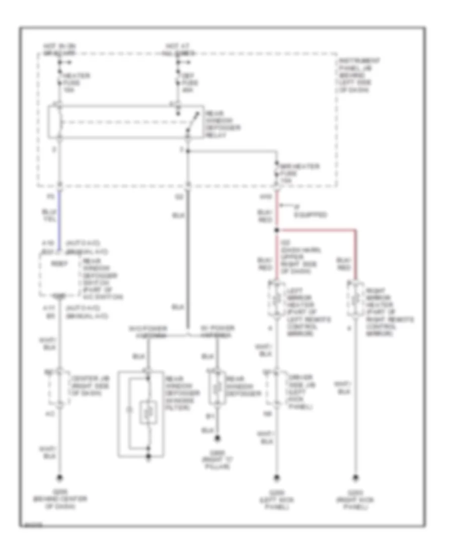
DEFOGGERS
Defogger Wiring Diagram for Toyota Avalon XLS 1999
List of elements for Defogger Wiring Diagram for Toyota Avalon XLS 1999:
- (auto a/c)
- (manual a/c)
- A10
- A11
- B11
- Center j/b (right side of dash)
- Def fuse 40a
- Driver side j/b (left kick panel)
- G200 (left kick panel)
- G203 (right kick panel)
- G206 (behind center of dash)
- G905 (right "c" pillar)
- Gnd
- H10
- Heater fuse 10a
- Hot at all times
- Hot in on or start
- I22 (dash harn, upper right side of dash)
- If equipped
- Instrument panel j/b (behind left side of dash)
- Left mirror heater (part of left remote control mirror)
- Mir heater fuse 10a
- Rdef
- Rear window defogger
- Rear window defogger (w/noise filter)
- Rear window defogger relay
- Rear window defogger switch (part of a/c switch)
- Right mirror heater (part of right remote control mirror)
- W/ power antenna
- W/o power antenna
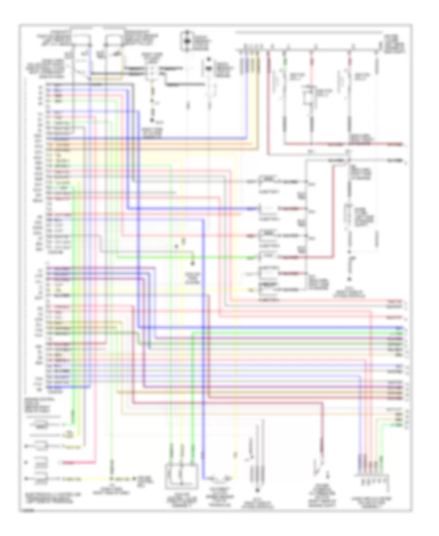
ENGINE PERFORMANCE
3.0L
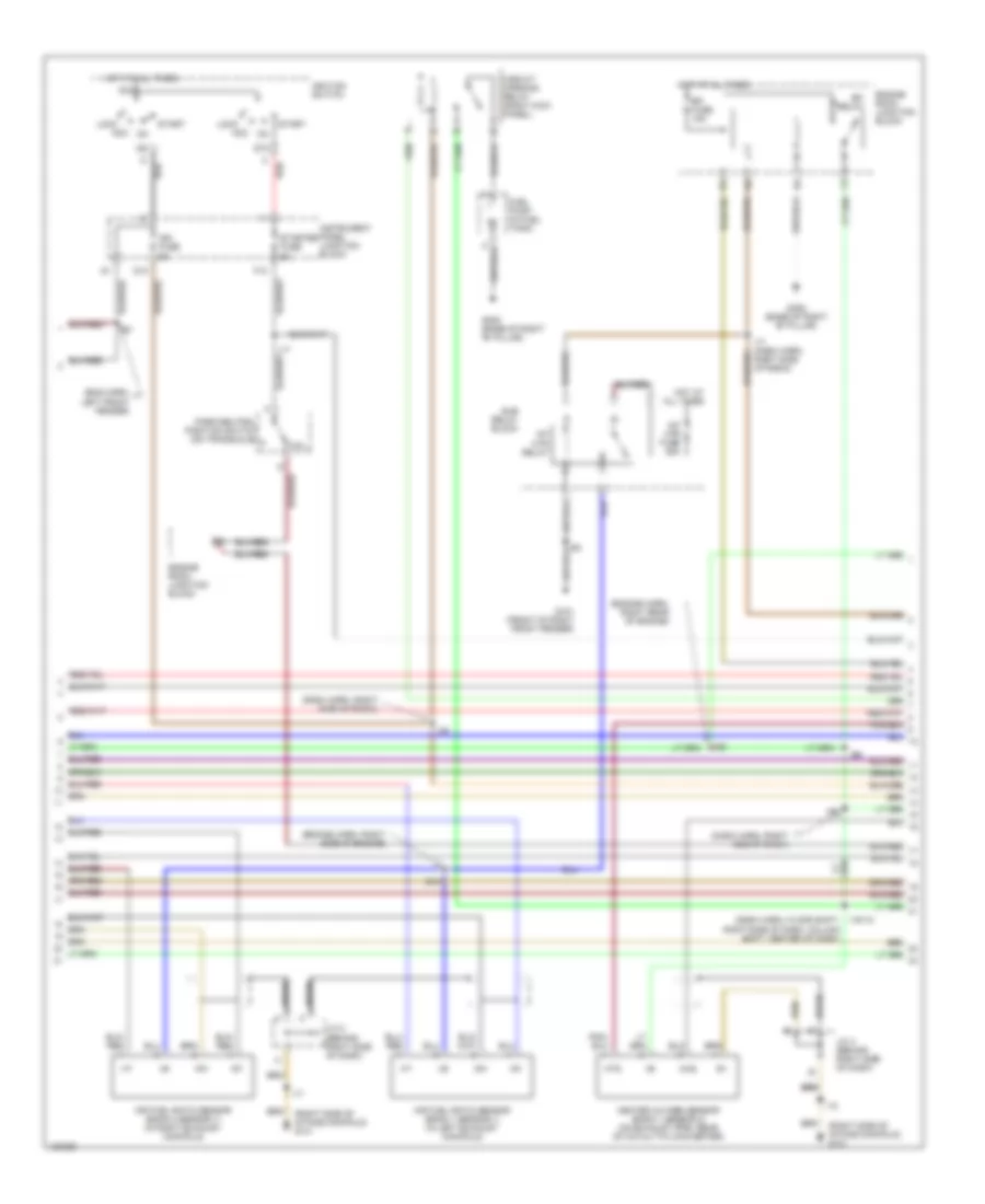
3.0L, Engine Performance Wiring Diagrams, California (1 of 4) for Toyota Avalon XLS 1999
List of elements for 3.0L, Engine Performance Wiring Diagrams, California (1 of 4) for Toyota Avalon XLS 1999:
- (dash harn, column shift-right side of radio, floor shift-upper right side of dash)
- (eng harn, right front of engine)
- (right side of dash) j/c 2
- (right side of intake manifold)
- A braid
- Acis
- Braid
- Camshaft position sensor (left rear of left cyl head)
- Conn e6
- Conn e7
- Cooling fans system
- Crankshaft position sensor (behind crank- shaft pulley)
- Cruise control ecu
- E01
- E02
- E03
- E10
- E10 (eng harn, right side of engine)
- E11
- E2g
- E9 (eng harn, right side of engine)
- Egls
- Egr
- Electronically controlled transmission solenoid (left side of transaxle)
- Engine control module (behind right side of dash)
- Evp
- G131
- G131 (right side of intake manifold)
- G22+
- Grd
- Htl
- Htr
- I16 (dash harn, right side of dash)
- I17
- I18/i21
- Idle air control valve (throttle body assembly)
- Igf
- Igniter (lower left rear corner of eng compt)
- Ignition coil 2
- Ignition coil 4
- Ignition coil 6
- Igt1
- Igt2
- Igt3
- Injector 1
- Injector 2
- Injector 3
- Injector 4
- Injector 5
- Injector 6
- Knkl
- Knkr
- Knock sensor 1 (top of engine)
- Knock sensor 2 (top of engine)
- Mass airflow meter (on air intake assembly)
- Nc2+
- Nc2-
- Ne+
- Ne-
- Noise filter (left side of engine compt)
- O/d direct clutch speed sensor (top of transaxle)
- Oxl
- Oxr
- Pnk
- Power steering oil pressure switch (right rear of engine compt)
- Red
- Rsc
- Rso
- Sln+
- Sln-
- Tha
- Thg
- Thw
- Vta1
3.0L, Engine Performance Wiring Diagrams, California (2 of 4) for Toyota Avalon XLS 1999
List of elements for 3.0L, Engine Performance Wiring Diagrams, California (2 of 4) for Toyota Avalon XLS 1999:
- (dash harn, right end of dash)
- (dash harn, right side of radio)
- (eng harn, left front fender)
- (engine harn, right rear of engine)
- (engine harn, right side of engine)
- (right side of intake manifold) g131
- A/f htr fuse 25a
- A/f htr relay
- Acc
- Af+
- Af-
- Air fuel ratio sensor (bank 1 sensor 1) (in left exhaust manifold)
- Air fuel ratio sensor (bank 2 sensor 1) (in right exhaust manifold)
- Am2
- Braid
- Circuit opening relay (right kick panel)
- D10
- E10
- Efi fuse 15a
- Efi relay
- Engine room junction block
- F12
- Fuel pump (in fuel tank)
- G101 (front of right front fender)
- G305 (base of right "b" pillar)
- Heated oxygen sensor (bank 1 sensor 2) (on exhaust pipe, rear of catalytic converter)
- Hot at all times
- Hts
- I17
- I17 (dash harn, right side of radio)
- I18
- I19/i12 (dash harn, floor shift: right side of dash, column shift: center of dash)
- I26
- I32
- Ig2
- Ign fuse 5a
- Ignition switch
- Instrument panel junction block
- J/c 2 (behind right side of dash)
- J/c 4 (behind right side of dash)
- Lock
- Oxs
- P/n
- Park/neutral position switch (on transaxle)
- Red
- St2
- Start
- Starter fuse 5a
- Sub relay block
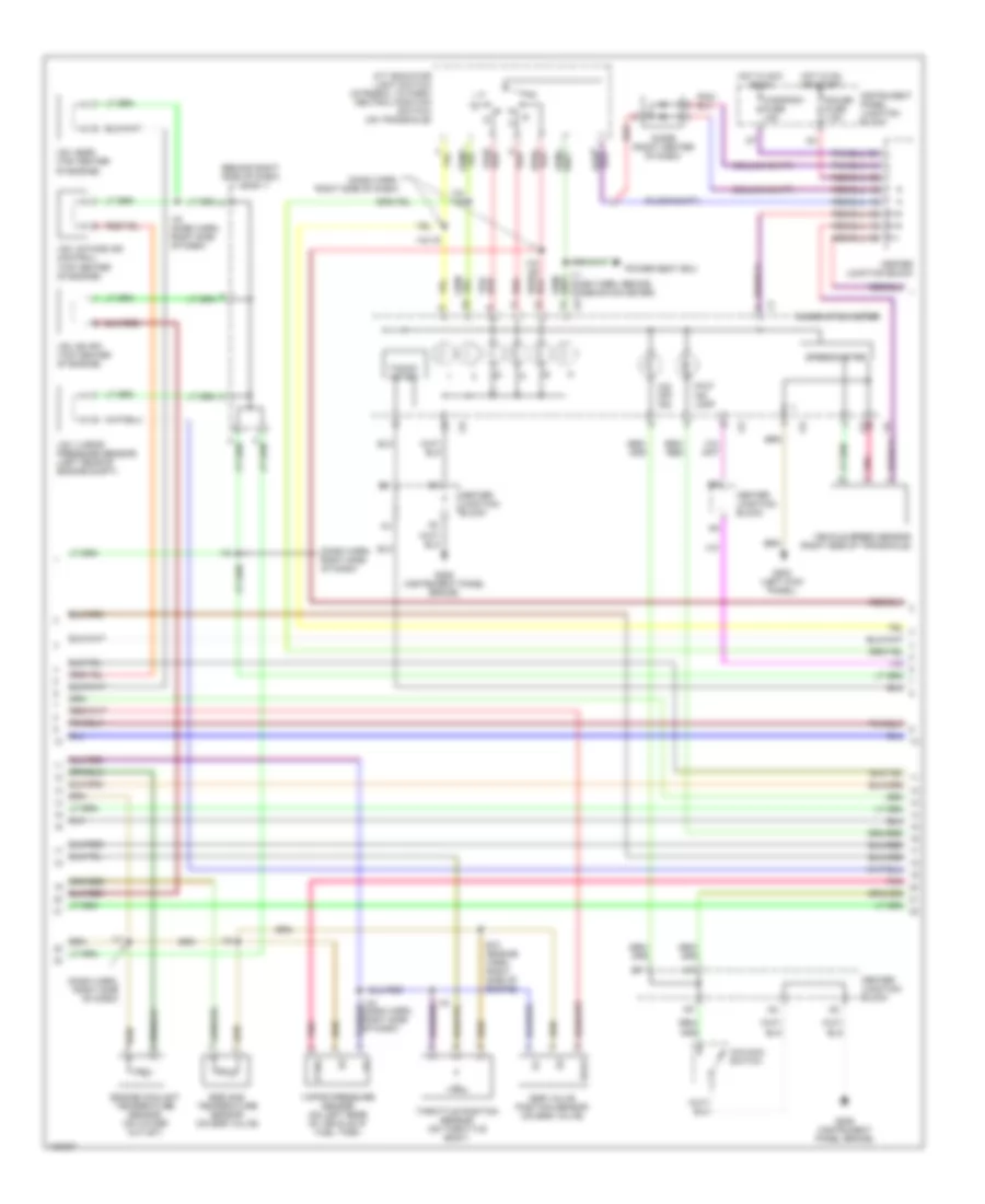
3.0L, Engine Performance Wiring Diagrams, California (3 of 4) for Toyota Avalon XLS 1999
List of elements for 3.0L, Engine Performance Wiring Diagrams, California (3 of 4) for Toyota Avalon XLS 1999:
- (behind right side of dash) j/c 3
- (column shift)
- (dash harn, right side of dash)
- (floor shift)
- A/t indicator light switch (integral to park/ neutral position switch) (on transaxle)
- Center junction block
- Cig/radio fuse 15a
- Combination meter
- Diode (right center of dash)
- E10 (engine harn, right side of engine)
- Egls
- Egr gas temperature sensor (on egr valve)
- Egr valve position sensor (on egr valve)
- Engine coolant temperature sensor (on water outlet)
- G200 (left kick panel)
- G206 (instrument panel brace)
- Gauge fuse 7.5a
- Hot in acc or on
- Hot in on or start
- I16
- I16 (dash harn, right side of dash)
- I17
- I18/ i19
- I18/ i20
- I18/i19
- Instrument panel junction block
- Malf ind lamp
- O/d main switch
- O/d off ind
- Pnk
- Power seat ecu
- Ptnk
- Red
- Speedometer
- Tacho- meter
- Throttle position sensor (on throttle body)
- Vapor pressure sensor (on left rear of vehicle at fuel tank)
- Vehicle speed sensor (right side of transaxle)
- Vsv (egr) (top center of engine)
- Vsv (evap) (top center of engine)
- Vsv (intake air control) (top center of engine)
- Vsv (vapor pressure sensor) (left rear of engine compt)
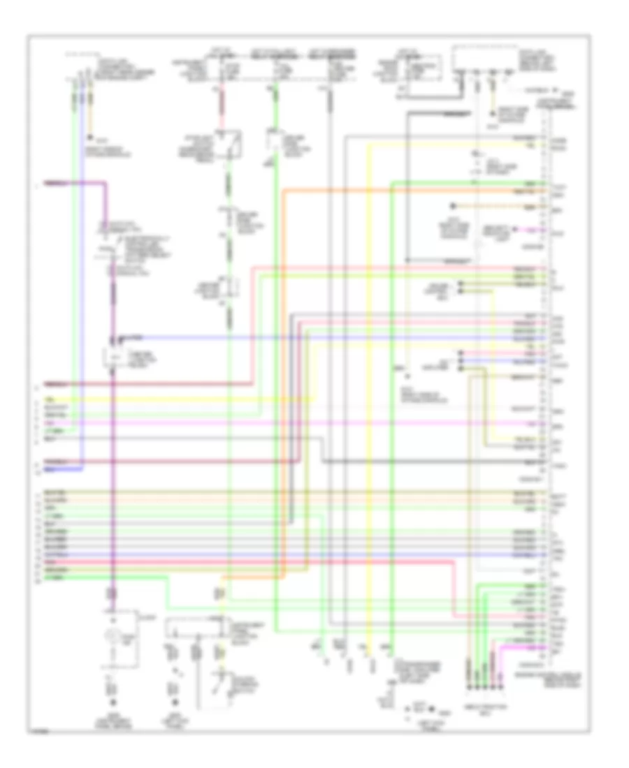
3.0L, Engine Performance Wiring Diagrams, California (4 of 4) for Toyota Avalon XLS 1999
List of elements for 3.0L, Engine Performance Wiring Diagrams, California (4 of 4) for Toyota Avalon XLS 1999:
- (auto a/c) (manual a/c)
- (instrument panel brace)
- (left kick panel)
- (right side of intake manifold)
- A/c
- A/c amplifier
- Abs & traction ecu
- Act
- Bat
- Batt
- Braided
- Center junction block
- Clock
- Code
- Conn e11
- Conn e12
- Conn e8
- Cruise control ecu
- Data link connector 1 (right rear corner of engine compt)
- Data link connector 3 (behind left side of dash)
- Driver side junction block
- E0m
- E10
- Efi+
- Efi-
- Electronically controlled transmission pattern select switch
- Els
- Els2
- Engine control module (behind right side of dash)
- Engine room junction block
- G131
- G131 (right side of intake manifold)
- G200
- G200 (left kick panel)
- G206
- G206 (instrument panel brace)
- Grd
- H12
- Hot at all times
- Hot at all times
- Hot w/defogger relay energized
- Hot w/taillight relay energized
- Hts
- Idlo
- Igsw
- Imld
- Instrument panel junction block
- J/c 4 (right side of dash)
- Ksw
- Mir heater fuse 10a
- Mrel
- Neo
- Nsw
- Obd/trac fuse 7.5a
- Od1
- Od2
- Oxs
- Pnk
- Ptnk
- Pwr
- Pwr ind
- Rxck
- Security indicator light
- Sil
- Spd
- Sta
- Stop fuse 15a
- Stoplight switch (on bracket, above brake pedal)
- Stp
- Tach
- Tail fuse 15a
- Te1
- Thwo
- Tpc
- Transponder key amplifier (left side of dash)
- Trc+
- Trc-
- Txct
- Unlock warning switch
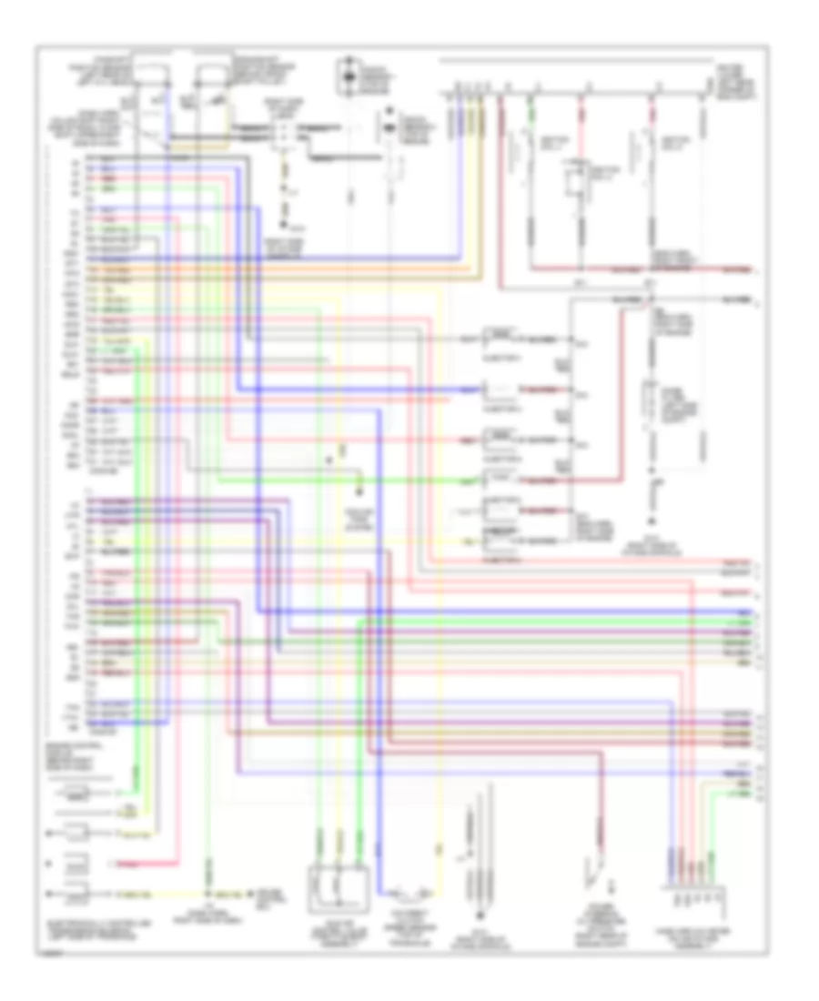
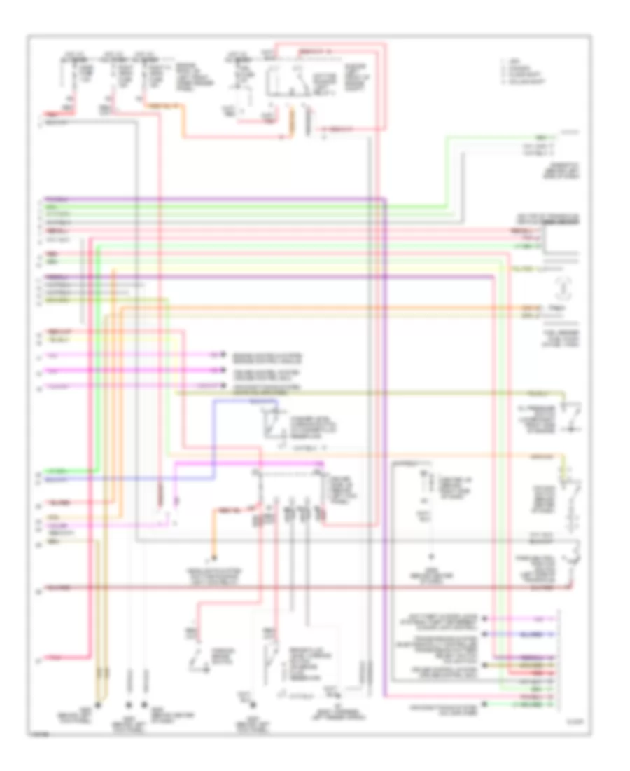
3.0L, Engine Performance Wiring Diagrams, Except California (1 of 4) for Toyota Avalon XLS 1999
List of elements for 3.0L, Engine Performance Wiring Diagrams, Except California (1 of 4) for Toyota Avalon XLS 1999:
- (dash harn, column shift-right side of radio, floor shift-upper right side of dash)
- (eng harn, right front of engine)
- (right side of dash) j/c 2
- (right side of intake manifold)
- A braid
- Acis
- Braid
- Camshaft position sensor (left rear of left cyl head)
- Conn e6
- Conn e7
- Cooling fans system
- Crankshaft position sensor (behind crank- shaft pulley)
- Cruise control ecu
- E01
- E02
- E03
- E10
- E10 (eng harn, right side of engine)
- E11
- E2g
- E9 (eng harn, right side of engine)
- Egls
- Egr
- Electronically controlled transmission solenoid (left side of transaxle)
- Engine control module (behind right side of dash)
- Evp
- G131
- G131 (right side of intake manifold)
- G22+
- Grd
- Htl
- Htr
- I16 (dash harn, right side of dash)
- I17
- I18/i21
- Idle air control valve (throttle body assembly)
- Igf
- Igniter (lower left rear corner of eng compt)
- Ignition coil 2
- Ignition coil 4
- Ignition coil 6
- Igt1
- Igt2
- Igt3
- Injector 1
- Injector 2
- Injector 3
- Injector 4
- Injector 5
- Injector 6
- Knkl
- Knkr
- Knock sensor 1 (top of engine)
- Knock sensor 2 (top of engine)
- Mass airflow meter (on air intake assembly)
- Nc2+
- Nc2-
- Ne+
- Ne-
- Noise filter (left side of engine compt)
- O/d direct clutch speed sensor (top of transaxle)
- Oxl
- Oxr
- Pnk
- Power steering oil pressure switch (right rear of engine compt)
- Red
- Rsc
- Rso
- Sln+
- Sln-
- Tha
- Thg
- Thw
- Vta1
3.0L, Engine Performance Wiring Diagrams, Except California (2 of 4) for Toyota Avalon XLS 1999
List of elements for 3.0L, Engine Performance Wiring Diagrams, Except California (2 of 4) for Toyota Avalon XLS 1999:
- (dash harn, floor shift: right side of dash, column shift: center of dash)
- (dash harn, right end of dash)
- (dash harn, right side of radio)
- (eng harn, left front fender)
- (engine harn, right rear of engine)
- (right side of intake manifold) g131
- Acc
- Am2
- Braid
- Circuit opening relay (right kick panel)
- D10
- E10
- Efi fuse 15a
- Efi relay
- Engine room junction block
- F12
- Fuel pump (in fuel tank)
- G131 (left side of intake manifold)
- G305 (base of right "b" pillar)
- Heated oxygen sensor (bank 1 sensor 1) (in right exhaust manifold)
- Heated oxygen sensor (bank 1 sensor 2) (on exhaust pipe, rear of catalytic converter)
- Heated oxygen sensor (bank 2 sensor 1) (in left exhaust manifold)
- Hot at all times
- Htl
- Htr
- Hts
- I17
- I18
- I19/i12
- I26
- I32
- Ig2
- Ign fuse 5a
- Ignition switch
- Instrument panel junction block
- J/c 2 (behind right side of dash)
- J/c 4 (behind right side of dash)
- Lock
- Oxl1
- Oxr1
- Oxs
- P/n
- Park/neutral position switch (on transaxle)
- Red
- St2
- Start
- Starter fuse 5a
3.0L, Engine Performance Wiring Diagrams, Except California (3 of 4) for Toyota Avalon XLS 1999
List of elements for 3.0L, Engine Performance Wiring Diagrams, Except California (3 of 4) for Toyota Avalon XLS 1999:
- (behind right side of dash) j/c 3
- (column shift)
- (dash harn, right side of dash)
- (dash harn, right side of radio)
- (floor shift)
- A/t indicator light switch (integral to park/ neutral position switch) (on transaxle)
- Center junction block
- Cig/radio fuse 15a
- Combination meter
- Diode (right center of dash)
- E10 (engine harn, right side of engine)
- Egls
- Egr gas temperature sensor (on egr valve)
- Egr valve position sensor (on egr valve)
- Engine coolant temperature sensor (on water outlet)
- G200 (left kick panel)
- G206 (instrument panel brace)
- Gauge fuse 7.5a
- Hot in acc or on
- Hot in on or start
- I12/ i29
- I16
- I16 (dash harn, right side of dash)
- I17
- I18/ i19
- I18/i19
- Instrument panel junction block
- Malf ind lamp
- O/d main switch
- O/d off ind
- Pnk
- Power seat ecu
- Ptnk
- Red
- Speedometer
- Tacho- meter
- Throttle position sensor (on throttle body)
- Vapor pressure sensor (on left rear of vehicle, at fuel tank)
- Vehicle speed sensor (right side of transaxle)
- Vsv (egr) (top center of engine)
- Vsv (evap) (top center of engine)
- Vsv (intake air control) (top center of engine)
- Vsv (vapor pressure sensor) (left rear of engine compt)
3.0L, Engine Performance Wiring Diagrams, Except California (4 of 4) for Toyota Avalon XLS 1999
List of elements for 3.0L, Engine Performance Wiring Diagrams, Except California (4 of 4) for Toyota Avalon XLS 1999:
- (auto a/c) (manual a/c)
- (instrument panel brace)
- (left kick panel)
- (right side of intake manifold)
- A/c
- A/c amplifier
- Abs & traction ecu
- Act
- Bat
- Batt
- Braided
- Center junction block
- Clock
- Code
- Conn e11
- Conn e12
- Conn e8
- Cruise control ecu
- Data link connector 1 (right rear corner of engine compt)
- Data link connector 3 (behind left side of dash)
- Driver side junction block
- E0m
- E10
- Efi+
- Efi-
- Electronically controlled transmission pattern select switch
- Els
- Els2
- Engine control module (behind right side of dash)
- Engine room junction block
- G131
- G131 (right side of intake manifold)
- G200
- G200 (left kick panel)
- G206
- G206 (instrument panel brace)
- Grd
- H12
- Hot at all times
- Hot at all times
- Hot w/defogger relay energized
- Hot w/taillight relay energized
- Hts
- Idlo
- Igsw
- Imld
- Instrument panel junction block
- J/c 4 (right side of dash)
- Ksw
- Mir heater fuse 10a
- Mrel
- Neo
- Nsw
- Obd/trac fuse 7.5a
- Od1
- Od2
- Oxs
- Pnk
- Ptnk
- Pwr
- Pwr ind
- Rxck
- Security indicator light
- Sil
- Spd
- Sta
- Stop fuse 15a
- Stoplight switch (on bracket, above brake pedal)
- Stp
- Tach
- Tail fuse 15a
- Te1
- Thwo
- Tpc
- Transponder key amplifier (left side of dash)
- Trc+
- Trc-
- Txct
- Unlock warning switch
EXTERIOR LIGHTS
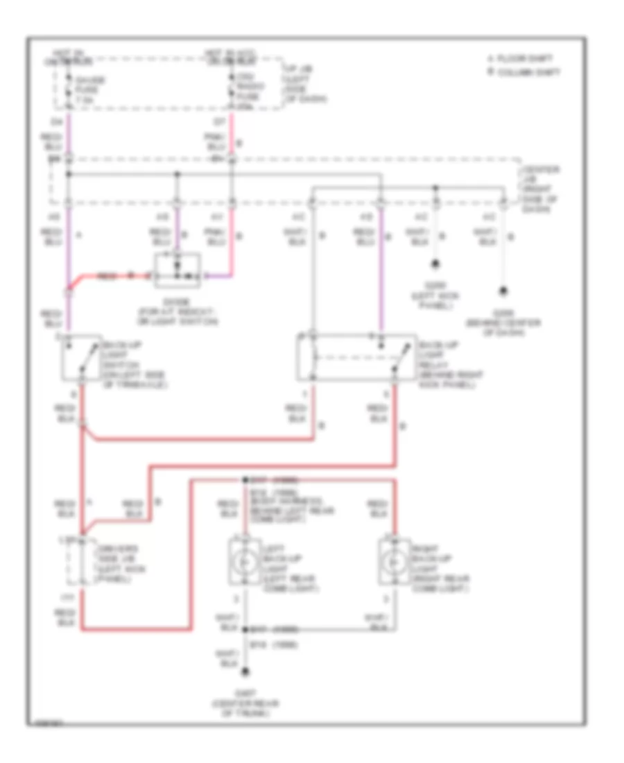
Back-up Lamps Wiring Diagram for Toyota Avalon XLS 1999
List of elements for Back-up Lamps Wiring Diagram for Toyota Avalon XLS 1999:
- (1998)
- (1999)
- B column shift
- B17
- B18
- B18 (body harness, behind left rear comb light)
- Back-up light relay (behind right kick panel)
- Back-up light switch (on left side of trnsaxle)
- Center j/b (right side of dash)
- Cig/ radio fuse 15a
- Diode (for a/t indicat- or light switch)
- Driver's side j/b (left kick panel)
- Floor shift a
- G200 (left kick panel)
- G206 (behind center of dash)
- G407 (center rear of trunk)
- Gauge fuse 7.5a
- Hot in acc, on or run
- Hot in on or run
- I/p j/b (left side of dash)
- I11
- L10
- Left back-up light (left rear comb light)
- Red
- Right back-up light (right rear comb light)
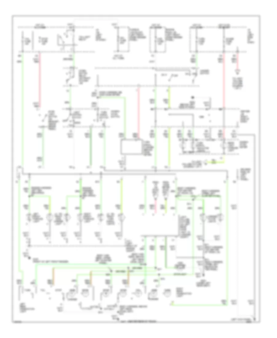
Exterior Lamps Wiring Diagram for Toyota Avalon XLS 1999
List of elements for Exterior Lamps Wiring Diagram for Toyota Avalon XLS 1999:
- (body har- ness, behind left rear comb light) b18
- (body har- ness, upper left quarter panel)
- (body harness, upper left quarter panel)
- (center rear of trunk)
- (left kick panel) g200
- Aj aj
- Ak ak
- Am1 fuse 80a
- B10
- B14
- B14 (body harness, upper left rear quar- ter panel)
- B17
- B18
- B22
- Center j/b (right side of dash)
- Combin- ation meter
- Combin- ation switch
- Driver's side j/b (left kick panel)
- Engine room j/b (left front inner fender panel)
- From comb meter (diag- ram 1 of 1)
- From i/p j/b (diag- ram 1 of 1)
- Fusible link block (left front inner fender panel)
- G100 (front of left front fender)
- G202 (behind left side of dash)
- G304 (under left rear seat)
- G407
- Guage fuse 7.5a
- Haz fuse 10a
- Hazard switch
- Head
- High mounted
- Hind comb meter) i7
- Hot at all times
- Hot in on or start
- I/p j/b (left side of dash)
- Integ- ration relay (on front of dash j/b)
- J/c 1 (left front of engine compt)
- Left fen- der apron) e7
- Left front parking light
- Left rear combination light
- Lh rh front side marker light
- Lh rh front turn signal lights
- License plate lights
- Light control switch
- Light failure fixture (on left rear comb light, in luggage compt)
- Marker
- Of trunk lid) b17
- Off
- Rear light warning light
- Right front parking light
- Right rear combination light
- Side
- Stop
- Stop fuse 15a
- Stop- light switch (on bracket, above brake pedal)
- Stoplight
- Tail
- Tail fuse 15a
- Taillight relay
- To light failure fixture (diagram 1 of 1)
- Turn
- Turn fuse 7.5a
- Turn signal flasher (behind comb meter)
- Turn signal indicator lights
- Turn signal switch
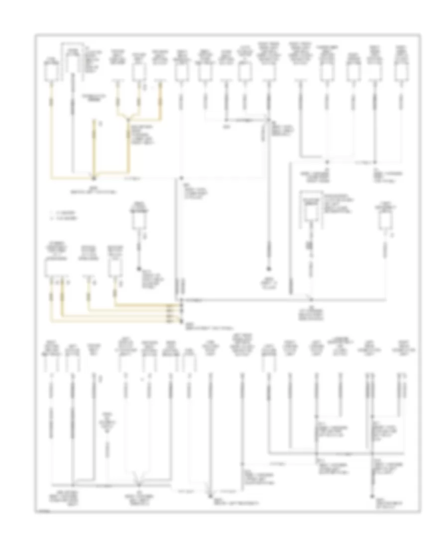
GROUND DISTRIBUTION
Ground Distribution Wiring Diagram (1 of 4) for Toyota Avalon XLS 1999
List of elements for Ground Distribution Wiring Diagram (1 of 4) for Toyota Avalon XLS 1999:
- (dash harness, right side of radio)
- (left front of engine compt) sub r/b
- (w/ abs & trac)
- (w/ abs)
- A/f relay heater
- A29
- A32
- A33
- Abs & traction actuator
- Abs & traction ecu
- Abs ecu & actuator
- B5 (body harness, center of wind- shield header)
- California
- Combination meter
- Data link connector
- Data link link connector
- E10 (engine harness, right side of engine)
- E3 (engine harness, right side of grille)
- E4 (engine harness, left side of grille)
- E9 (engine harness, right rear of engine)
- Efi relay
- Engine control module
- Engine hood courtesy light switch
- Engine main relay
- Engine room junction block (on left front inner fender panel)
- Fan relay
- G100 (front of left front fender)
- G101 (front of right front fender)
- G131 (on intake manifold)
- G902 (left side of roof)
- Headlight cleaner motor
- Heated oxygen sensor (bank 1 sensor 1)
- Heated oxygen sensor (bank 1 sensor 2)
- Heated oxygen sensor (bank 2 sensor 1)
- I17 (dash harness, right side of radio)
- I18
- Igniter
- Junction connector 1 (left front of engine compt)
- Junction connector 2 (behind right center of dash)
- Junction connector 4 (behind right center of dash)
- Left fog- light
- Left front side marker light
- Left front turn signal/ parking light
- Moonroof control relay
- Moonroof control switch
- Moonroof limit switch & motor
- Noise filter (for ignition)
- Radiator fan motor
- Right fog- light
- Right front side marker light
- Right front turn signal/ parking light
- To right vanity light (diagram 2 of 4)
- Water temperature switch 1
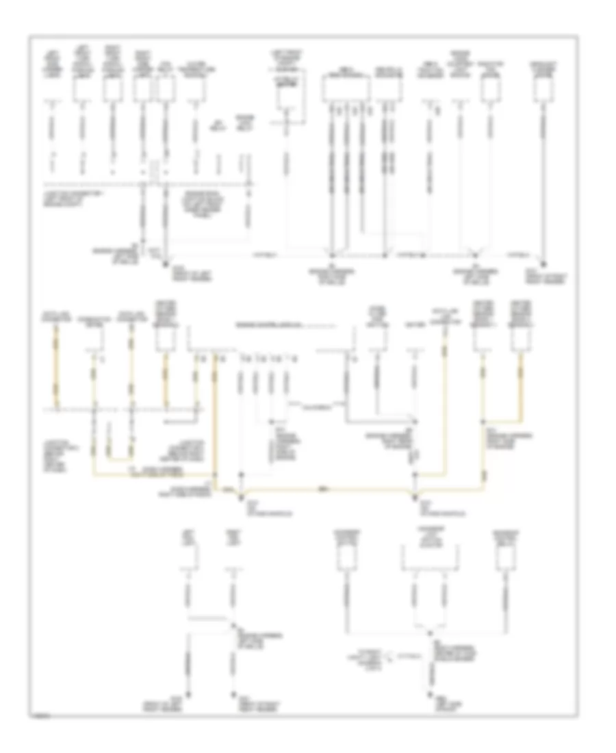
Ground Distribution Wiring Diagram (2 of 4) for Toyota Avalon XLS 1999
List of elements for Ground Distribution Wiring Diagram (2 of 4) for Toyota Avalon XLS 1999:
- (canada only)
- B1 (body harness, inside driver side door)
- B13
- B2 (body harness, inside driver side door)
- B4 (body harness, left 'a' pillar)
- Brake fluid level warning switch
- Daytime running light relay (main)
- Driver side junction block (upper left kick panel)
- Drl 3 relay
- Drl 4 relay
- E10
- E7 (engine harness, left fender apron)
- From g902 (diagram 1 of 4)
- From ignition main relay (diagram 2 of 4)
- Front personal light
- Front wiper/ washer switch
- G200 (left kick panel)
- Headlight cleaner relay
- I1 (i/p harness, behind left kick panel)
- I13
- I4 (dash harness, left end of dash)
- Ignition main relay
- Instrument panel junction block (behind left side of dash)
- Integration relay
- Key interlock solenoid
- Left door key lock & unlock switch
- Left front door lock motor & door unlock detection switch
- Left front seat heater control switch
- Left mirror heater
- Left rear personal light
- Left vanity light
- Light control/ dimmer switch
- N10
- N11
- Power main relay
- Power window master switch
- Right vanity light
- Sub r/b (left front of engine compt)
- To g200 (diagram 3 of 4)
- To g304 (diagram 4 of 4)
- To left front seat heater control switch (diagram 2 of 4)
- Transponder key amplifier
- Turn signal flasher relay
- Unlock warning switch
- Washer level warning switch
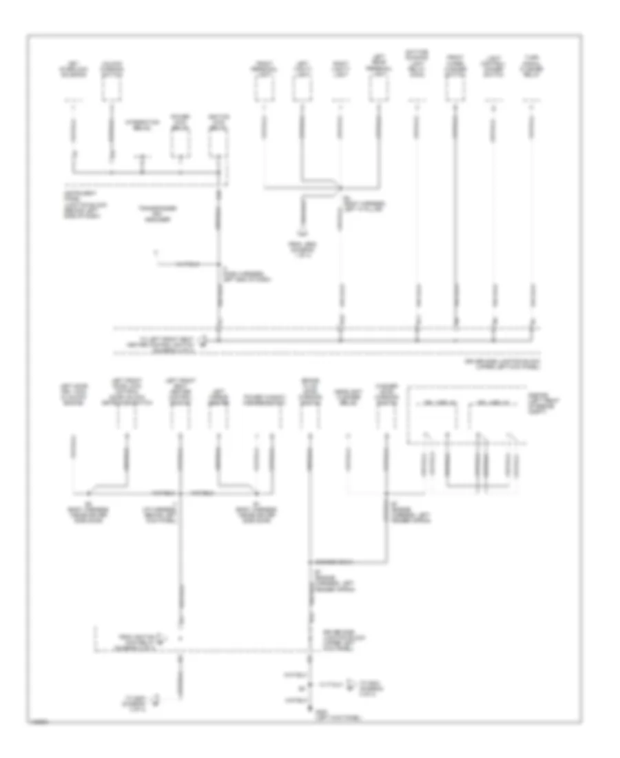
Ground Distribution Wiring Diagram (3 of 4) for Toyota Avalon XLS 1999
List of elements for Ground Distribution Wiring Diagram (3 of 4) for Toyota Avalon XLS 1999:
- (diagram 3 of 4)
- A/c amplifier
- A/c blower motor linear controller
- A/c dual pressure switch
- A/c switch
- A12
- Air vent mode control servo motor
- Automatic a/c
- Back-up light relay (column shift)
- Blower resistor
- C16
- Center air bag sensor assembly
- Center airbag sensor assembly
- Center junction block (behind right side of dash)
- Cigarette lighter
- Clock
- Column shifter
- Combin- ation meter
- Cruise control actuator
- Cruise control ecu
- Cruise control switch
- Data link conn
- Driver side junction block (behind left kick panel)
- Floor shifter
- From driver side junction block (diagram 2 of 4)
- From heater control switch e
- Front wiper motor
- G200 (behind left kick panel)
- G203 (behind right kick panel)
- G206 (behind center of dash)
- Glove box light switch
- H14
- Heater relay
- High beam indicator (canada only)
- I11 (dash harness, behind combination meter)
- I12 (dash harness, top center of dash)
- I19 (or i20) (dash harness, right side of dash)
- I20 (dash harness, behind right side of dash)
- I22 (dash harn, upper right side of dash)
- I28 (dash harness, left side of dash)
- I7 (dash harness, behind combination meter)
- Left lo beam headlight
- Low speed blower resistor
- Luggage compartment door opener switch
- Manual a/c
- Mode dial switch (heater control)
- O/d main switch
- Rear window defogger switch
- Remote control mirror switch
- Rheostat
- Right lo beam headlight
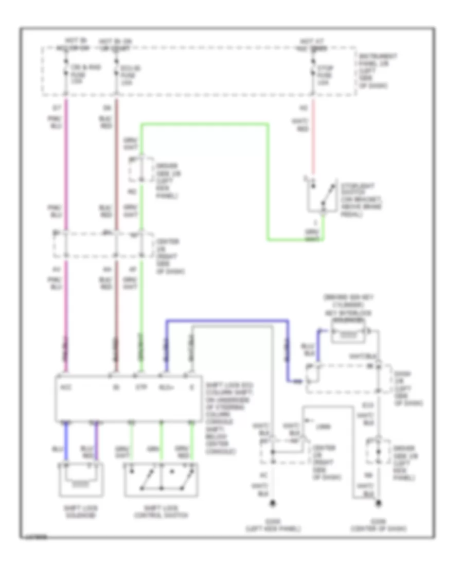
- Shift lock ecu
- To back-up light relay (diagram 3 of 4)
- Traction cut switch
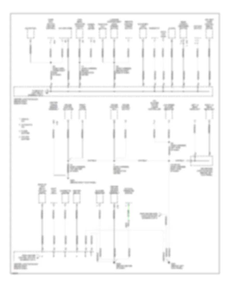
Ground Distribution Wiring Diagram (4 of 4) for Toyota Avalon XLS 1999
List of elements for Ground Distribution Wiring Diagram (4 of 4) for Toyota Avalon XLS 1999:
- (body harn, top center of trunk lid)
- (body harn, under right 'd' pillar)
- (body harness, upper left quarter panel)
- Auto antenna motor & relay
- B13 (body harness, upper left quarter panel)
- B14
- B17
- B17 (body harness, top center of trunk lid)
- B18 (body harness, behind left taillight)
- B20
- B23 (or b24) (body harness, under driver,s seat)
- B23 (or b24) (body harness, under left front seat)
- B25
- B3 (body harness, left front door sill)
- B6 (body harn, right front door sill)
- B7 (body harness, inside right front door)
- Blower switch (manual a/c)
- Combination meter
- Door lock control receiver
- Driver's seat control switch
- E11
- Engine room junction block (on left front inner fender panel)
- From b3 (diagram 2 of 4)
- Fuel pump
- Fuel sender
- G200 (behind left kick panel)
- G203 (behind right kick panel)
- G304 (below left rear seat)
- G407 (center rear of trunk)
- G413 (front of right rear quarter panel)
- G905 (right "c"
- H15
- High mounted stop- light
- I/p junction block (behind left side of dash)
- I25 (i/p harness, behind right side of dash)
- I31 (body harness, right kick panel)
- Left buckle switch
- Left buckle switch (w/o power seat)
- Left license plate light
- Left rear combination light
- Left rear door lock motor & door unlock detection switch
- Light failure sensor
- Luggage compartment key unlock switch
- Noise filter
- P24
- P25
- Pass seat control switch
- Passenger seat heater control switch
- Pillar)
- Power seat ecu
- Power seat position sensor
- R13
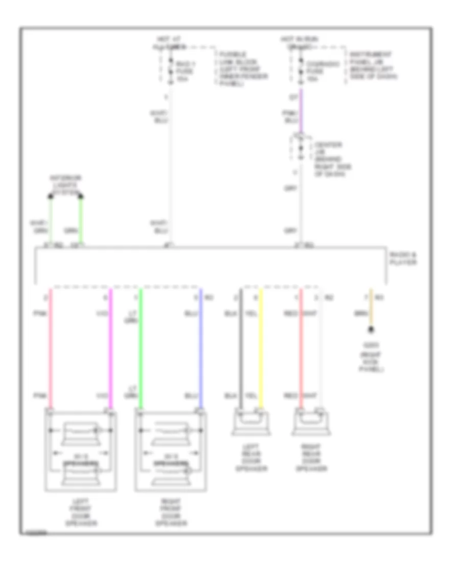
- Radio & player (w/ 4 & 6 speakers)
- Rear window defogger
- Right door lock & unlock switch
- Right door lock control switch
- Right front door lock motor & door unlock detection switch
- Right license plate light
- Right mirror heater
- Right rear combination light
- Right rear door lock motor & door unlock detection switch
- Right rear personal light
- Seat heater (driver seatback)
- Seat heater (pass seatback)
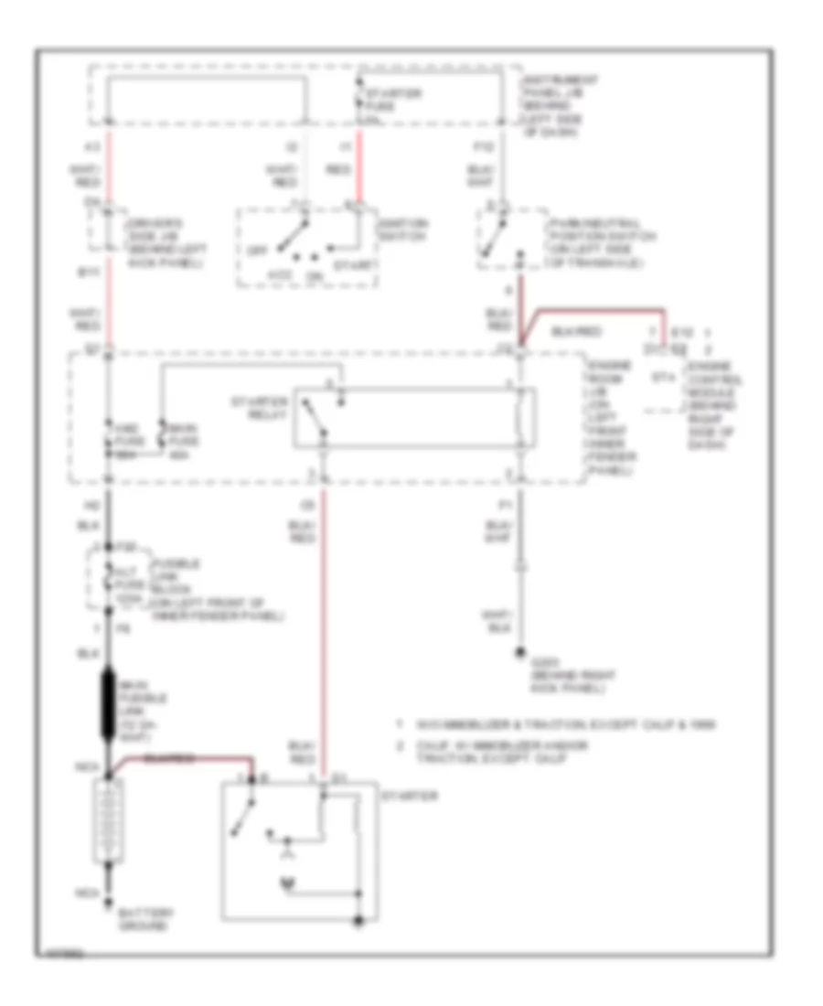
- Starter relay
- Stereo component amplifier (w/ 7 speakers)
- Theft deterrent ecu
- W/ memory
- W/ power seats
- W/o memory
HEADLIGHTS
Autolamps Wiring Diagram, with DRL (1 of 2) for Toyota Avalon XLS 1999
List of elements for Autolamps Wiring Diagram, with DRL (1 of 2) for Toyota Avalon XLS 1999:
- (ar or br)
- (as or bs)
- (left kick panel) g200
- (on left front inner fender panel) engine room j/b
- (right kick panel) g203
- A18
- Auto
- Automatic light control sensor (on top left side of dash)
- B13
- Center j/b (behind right side of dash)
- Combination switch
- Cty
- Daytime running light relay (main) (behind left side of dash)
- Dimmer switch
- Dome fuse 7.5a
- Driver side j/b (behind left kick panel)
- Exterior lights system
- Flash
- Fog
- Foglight switch
- Fusible link block (on left front inner fender panel)
- Gauge fuse 7.5a
- Head
- Head relay
- High
- Hot at all times
- Hot in on or start
- I19 (floor shift) i20 (column shift)
- I9 (lower left side of dash)
- Instrument cluster system
- Instrument panel j/b (behind left side of dash)
- Integration relay
- Left lo head fuse 10a
- Left low headlight
- Light control switch
- Low
- Main fuse 40a
- N11
- Off
- Parking brake switch (behind dash, on parking brake lever bracket)
- Red
- Right lo head fuse 10a
- Right low headlight
- Starting/ charging system
- Tail
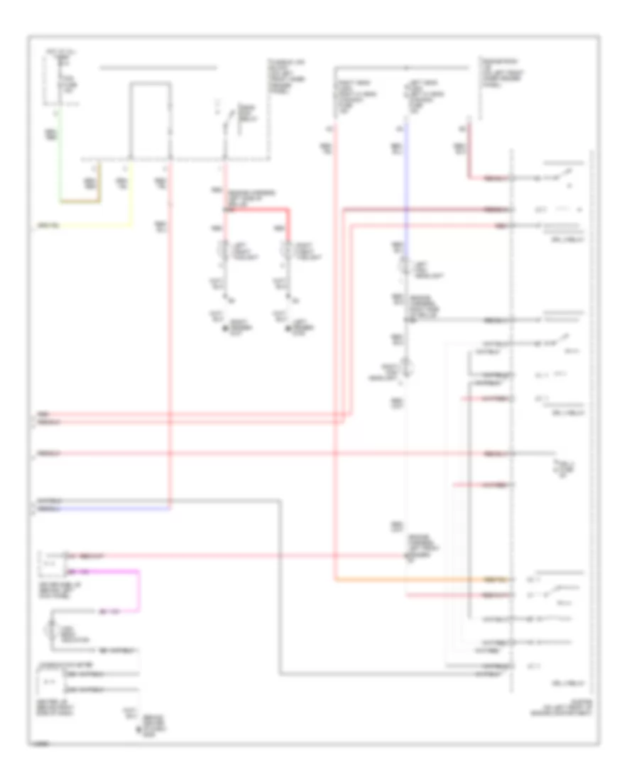
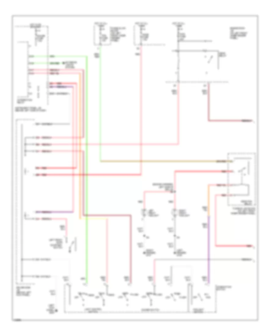
Autolamps Wiring Diagram, with DRL (2 of 2) for Toyota Avalon XLS 1999
List of elements for Autolamps Wiring Diagram, with DRL (2 of 2) for Toyota Avalon XLS 1999:
- (behind center of dash) g206
- (engine harness, left front fender) e7
- (engine harness, left side of grille) e4
- (left fender) g106
- (right fender) g107
- Center j/b (behind right side of dash)
- Combination meter
- Driver side j/b (behind left kick panel)
- Drl 2 fuse 5a
- Drl 2 relay
- Drl 3 relay
- Drl 4 relay
- Engine room j/b (on left front inner fender panel)
- Fog fuse 15a
- Fusible link block (on left front inner fender panel)
- Head fog relay
- High beam indicator
- Hot at all times
- Left front door courtesy switch
- Left front foglight
- Left head (usa) left hi head (canada) fuse 15a
- Left high headlight
- Red
- Red/ (engine harness, right side of grille) e3
- Right front foglight
- Right head (usa) right hi head (canada) fuse 15a
- Right high headlight
- Sub r/b (on left front of engine compartment)
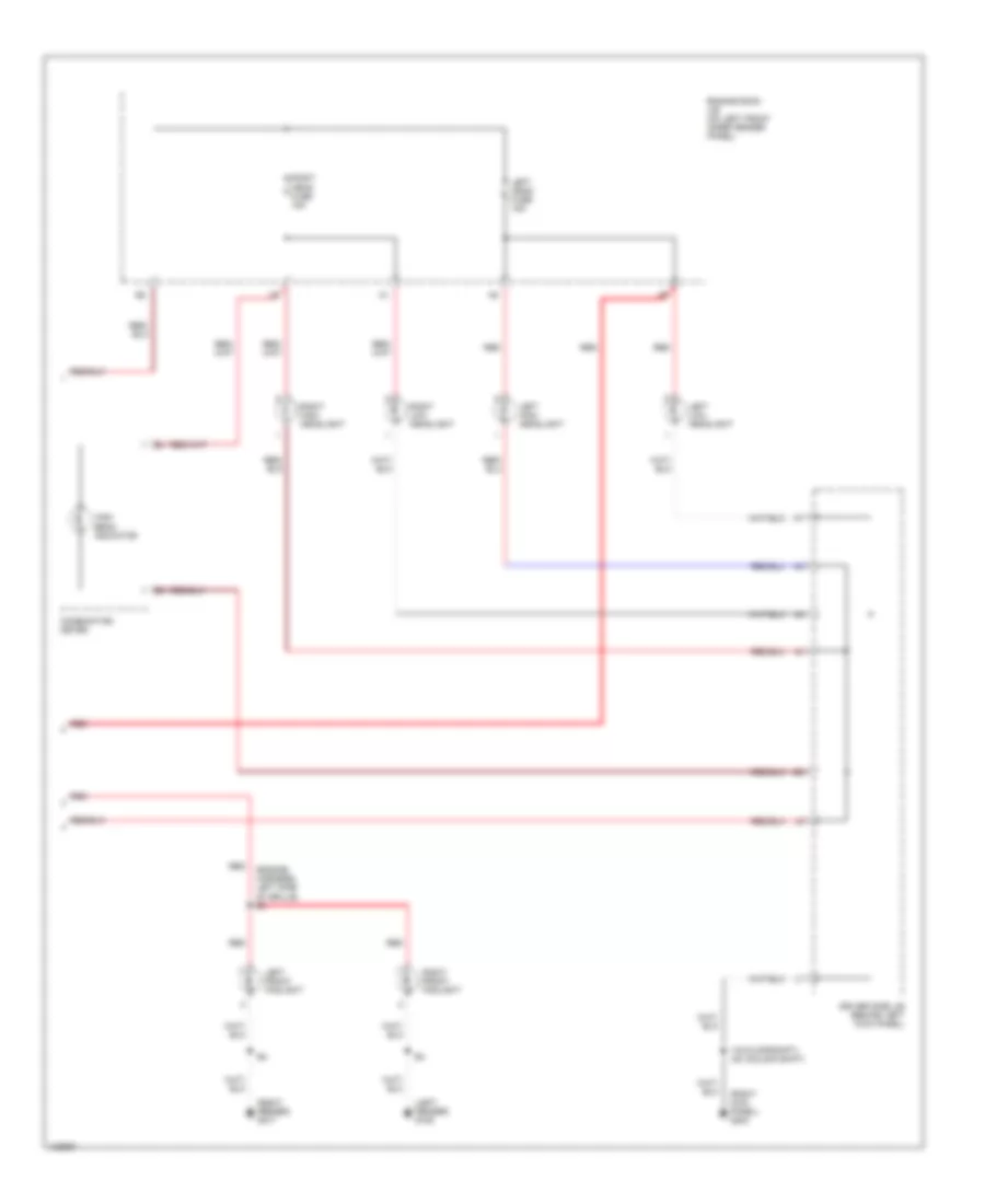
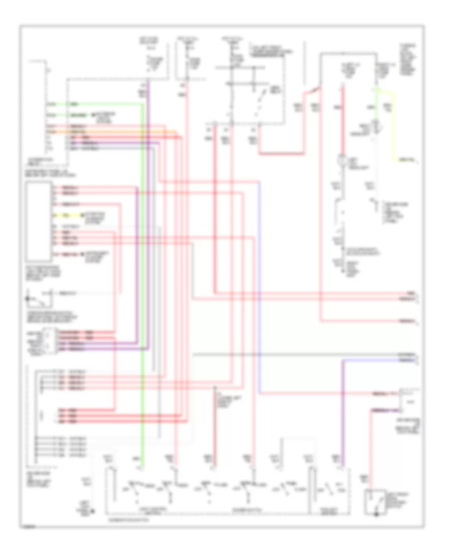
Autolamps Wiring Diagram, without DRL (1 of 2) for Toyota Avalon XLS 1999
List of elements for Autolamps Wiring Diagram, without DRL (1 of 2) for Toyota Avalon XLS 1999:
- (bs or as)
- (left kick panel) g200
- A18
- Auto
- Automatic light control sensor (on top left side of dash)
- Center j/b (behind right side of dash)
- Combination switch
- Cty
- Dimmer switch
- Dome fuse 7.5a
- Driver side j/b (behind left kick panel)
- Engine room j/b (on left front inner fender panel)
- Exterior lights system
- Flash
- Fog
- Fog fuse 15a
- Foglight switch
- Fusible link block (on left front inner fender panel)
- Gauge fuse 7.5a
- Head
- Head fog relay
- Head relay
- High
- Hot at all times
- Hot in on or start
- Instrument panel j/b (behind left side of dash)
- Integration relay
- Left front door courtesy switch
- Light control switch
- Low
- Main fuse 40a
- Off
- Red
- Tail
Autolamps Wiring Diagram, without DRL (2 of 2) for Toyota Avalon XLS 1999
List of elements for Autolamps Wiring Diagram, without DRL (2 of 2) for Toyota Avalon XLS 1999:
- (engine harness, left side of grille) e4
- (left fender) g106
- (right fender) g107
- (right kick panel) g203
- Combination meter
- Driver side j/b (behind left kick panel)
- Engine room j/b (on left front inner fender panel)
- High beam indicator
- I19 (floor shift) i20 (column shift)
- Left front foglight
- Left head fuse 15a
- Left high headlight
- Left low headlight
- Red
- Right front foglight
- Right head fuse 15a
- Right high headlight
- Right low headlight
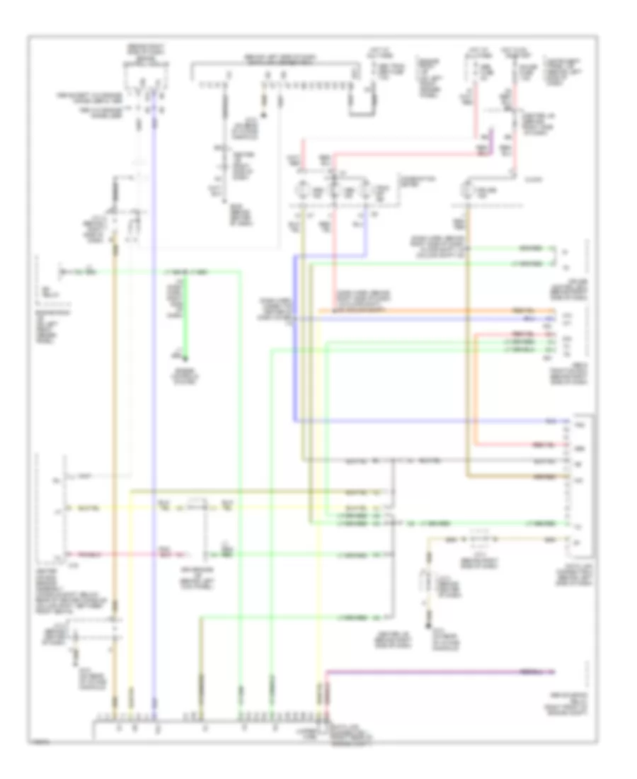
Headlamps Wiring Diagram, with DRL (1 of 2) for Toyota Avalon XLS 1999
List of elements for Headlamps Wiring Diagram, with DRL (1 of 2) for Toyota Avalon XLS 1999:
- (ar or br)
- (left kick panel) g200
- (on left front inner fender panel) engine room j/b
- (right kick panel) g203
- A15
- A16
- A17
- A18
- B13
- Center j/b (behind right side of dash)
- Combination switch
- Daytime running light relay (main) (behind left side of dash)
- Dimmer switch
- Dome fuse 7.5a
- Driver side j/b (behind left kick panel)
- E10
- Exterior lights system
- F11
- Flash
- Fog
- Foglight switch
- Fusible link block (on left front inner fender panel)
- Gauge fuse 7.5a
- Head
- Head relay
- High
- Hot at all times
- Hot in on or start
- I19 (floor shift) i20 (column shift)
- I9 (lower left side of dash)
- Instrument cluster system
- Instrument panel j/b (behind left side of dash)
- Integration relay
- Left front door courtesy switch
- Left lo head fuse 10a
- Left low headlight
- Light control switch
- Low
- Main fuse 40a
- N11
- Off
- Parking brake switch (behind dash, on parking brake lever bracket)
- Red
- Right lo head fuse 10a
- Right low headlight
- Starting/ charging system
- Tail
Headlamps Wiring Diagram, with DRL (2 of 2) for Toyota Avalon XLS 1999
List of elements for Headlamps Wiring Diagram, with DRL (2 of 2) for Toyota Avalon XLS 1999:
- (behind center of dash) g206
- (engine harness, left front fender) e7
- (engine harness, left side of grille) e4
- (left fender) g106
- (right fender) g107
- Center j/b (behind right side of dash)
- Combination meter
- Driver side j/b (behind left kick panel)
- Drl 2 fuse 5a
- Drl 2 relay
- Drl 3 relay
- Drl 4 relay
- Engine room j/b (on left front inner fender panel)
- Fog fuse 15a
- Fusible link block (on left front inner fender panel)
- Head fog relay
- High beam indicator
- Hot at all times
- Left front foglight
- Left head (usa) left hi head (canada) fuse 15a
- Left high headlight
- Red
- Red/ (engine harness, right side of grille) e3
- Right front foglight
- Right head (usa) right hi head (canada) fuse 15a
- Right high headlight
- Sub r/b (on left front of engine compartment)
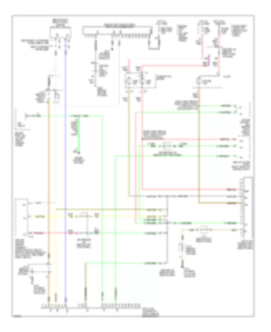
Headlamps Wiring Diagram, without DRL (1 of 2) for Toyota Avalon XLS 1999
List of elements for Headlamps Wiring Diagram, without DRL (1 of 2) for Toyota Avalon XLS 1999:
- (engine harness, left side of grille) e4
- (left fender) g106
- (left kick panel) g200
- (right fender) g107
- A15
- A16
- A17
- A18
- Combination switch
- Dimmer switch
- Dome fuse 7.5a
- Driver side j/b (behind left kick panel)
- E10
- Engine room j/b (on left front inner fender panel)
- Exterior lights system
- F11
- Flash
- Fog
- Fog fuse 15a
- Foglight switch
- Fusible link block (on left front inner fender panel)
- Gauge fuse 7.5a
- Head
- Head fog relay
- Head relay
- High
- Hot at all times
- Hot in on or start
- Instrument panel j/b (behind left side of dash)
- Integration relay
- Left front door courtesy switch
- Left front foglight
- Light control switch
- Low
- Main fuse 40a
- Off
- Red
- Right front foglight
- Tail
Headlamps Wiring Diagram, without DRL (2 of 2) for Toyota Avalon XLS 1999
List of elements for Headlamps Wiring Diagram, without DRL (2 of 2) for Toyota Avalon XLS 1999:
- (right kick panel) g203
- Combination meter
- Driver side j/b (behind left kick panel)
- Engine room j/b (on left front inner fender panel)
- High beam indicator
- I19 (floor shift) i20 (column shift)
- Left head fuse 15a
- Left high headlight
- Left low headlight
- Red
- Right head fuse 15a
- Right high headlight
- Right low headlight
HORN
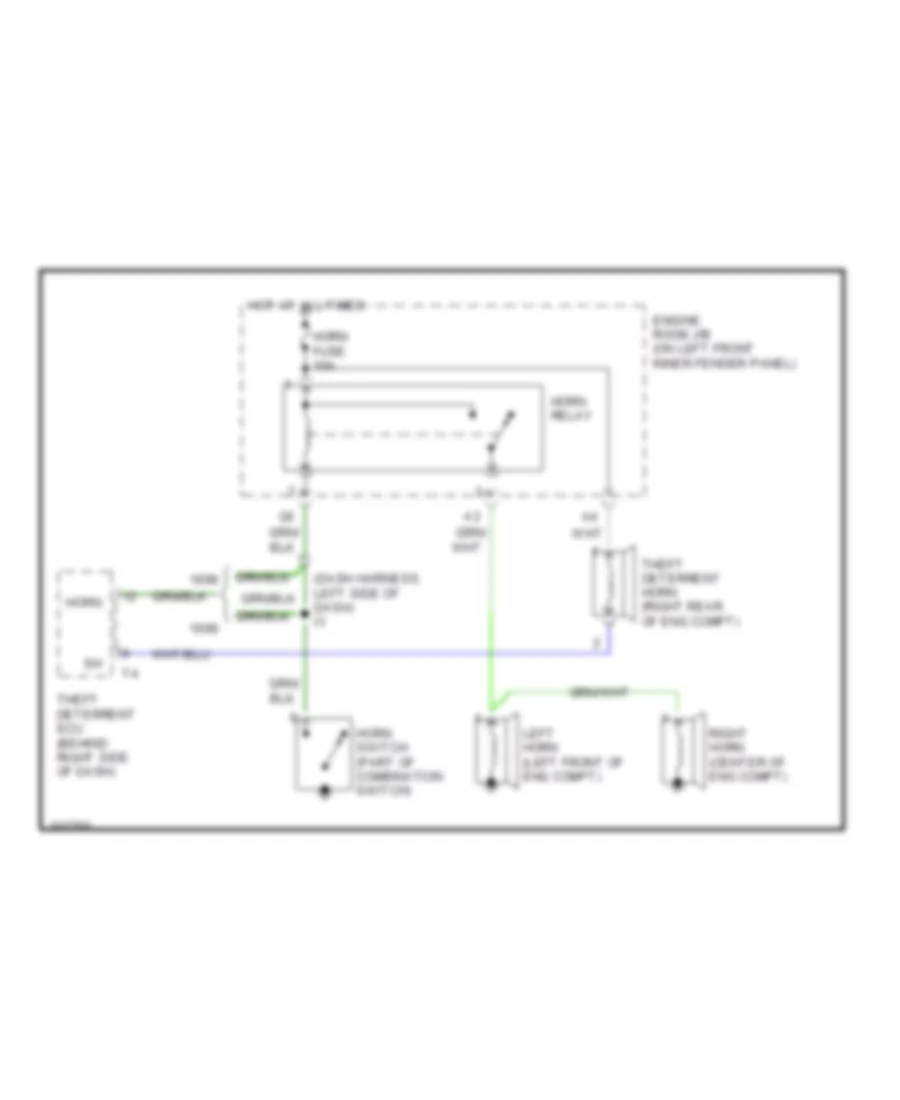
Horn Wiring Diagram for Toyota Avalon XLS 1999
List of elements for Horn Wiring Diagram for Toyota Avalon XLS 1999:
- (dash harness, left side of dash) i3
- Engine room j/b (on left front inner fender panel)
- Horn
- Horn fuse 10a
- Horn relay
- Horn switch (part of combination switch)
- Hot at all times
- Left horn (left front of eng compt)
- Right horn (center of eng compt)
- Theft deterrent ecu (behind right side of dash)
- Theft deterrent horn (right rear of eng compt)
INSTRUMENT CLUSTER
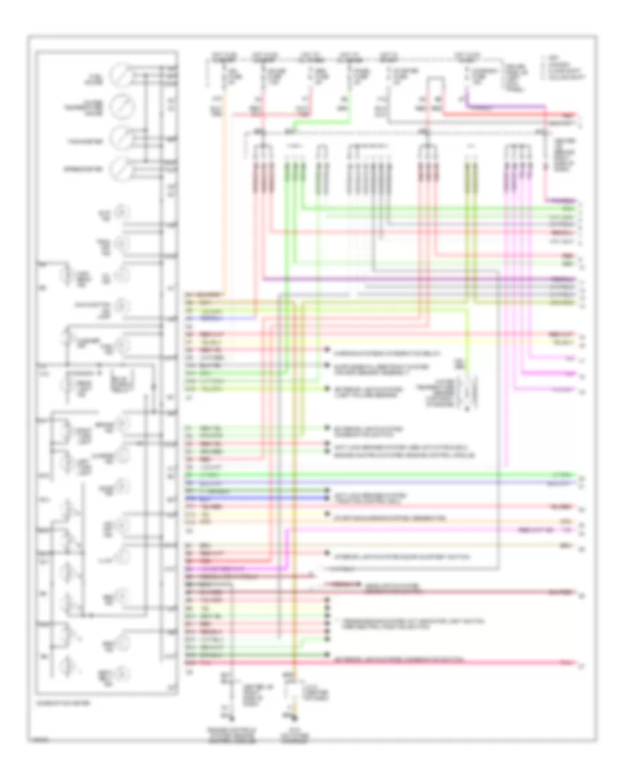
Instrument Cluster Wiring Diagram (1 of 2) for Toyota Avalon XLS 1999
List of elements for Instrument Cluster Wiring Diagram (1 of 2) for Toyota Avalon XLS 1999:
- (canada)
- A10
- A11
- A12
- A13
- Abs ind
- Anti-lock brakes system (abs actuator & ecu)
- Anti-lock brakes system (traction control ecu)
- B10
- B11
- B12
- B13
- B14
- B15
- B16
- Brake ind
- Bulb check relay
- C10
- C11
- C12
- C13
- Canada
- Center j/b (behind right side of dash)
- Center j/b (right side of dash)
- Charge ind
- Cig/radio fuse 15a
- Column shift
- Combination meter
- D10
- Door ind
- Driver side j/b (left kick panel)
- Engine controls system (engine control module)
- Exterior lights system (combination switch)
- Exterior lights system (light failure sensor)
- F12
- Floor shift
- Fuel gauge
- Fuel ind
- G131 (on intake manifold)
- Gauge fuse 7.5a
- Headlights system (combination switch)
- High beam ind
- Hot at all times
- Hot in on & acc
- Hot in on & start
- Hot in start
- Ign fuse 5a
- Illum
- Interior lights system (door courtesy switch)
- J/c 2 (center of dash)
- Left turn light
- Malfunction ind lamp
- O/d off ind
- Oil ind
- Panel fuse 5a
- Pnk
- Rear light ind
- Red
- Right turn light
- Seat belt ind
- Slip ind
- Speedometer
- Srs fuse 5a
- Srs ind
- Starter fuse 5a
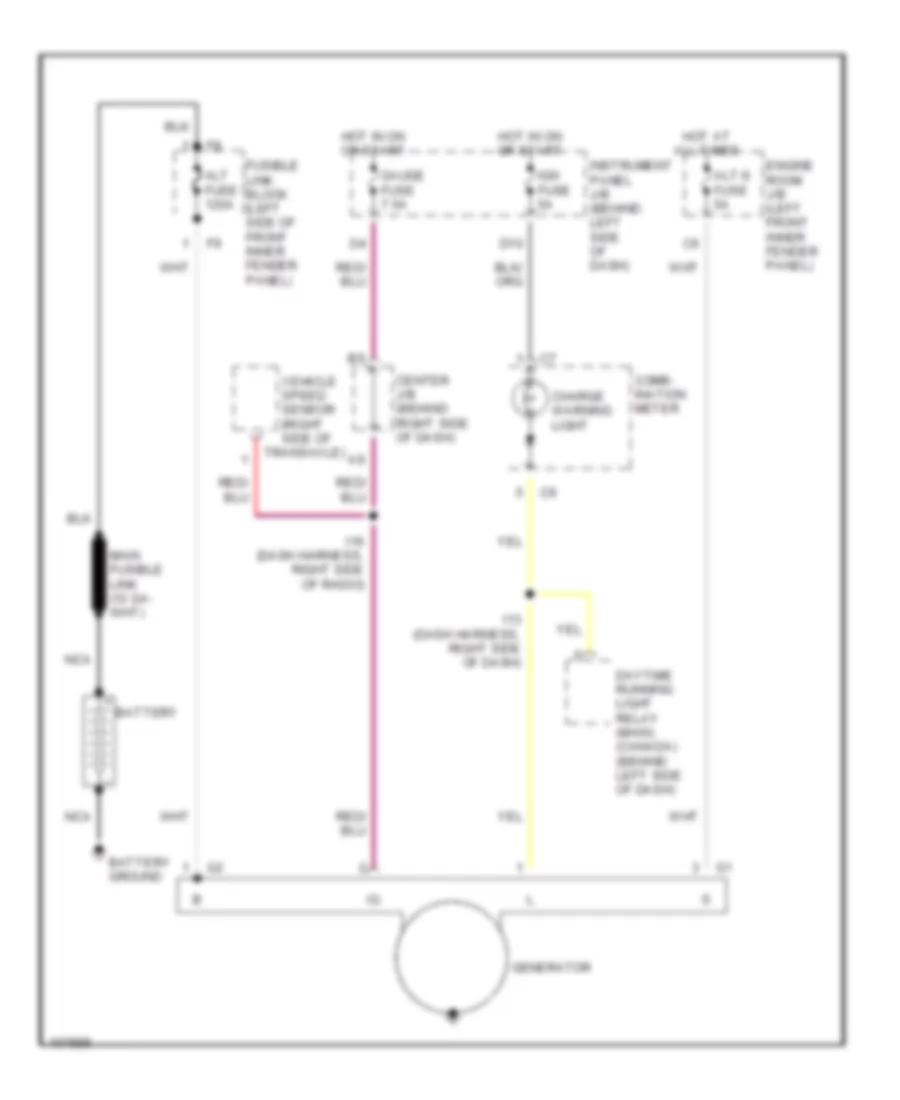
- Starting/charging system (generator)
- Tachometer
- Trac off ind
- Transmissions system (a/t indicator light switch, park/neutral position switch)
- Usa
- Warning systems (integration relay)
- Washer ind
- Water temperature gauge
- Water temperature sender (top right of engine)
Instrument Cluster Wiring Diagram (2 of 2) for Toyota Avalon XLS 1999
List of elements for Instrument Cluster Wiring Diagram (2 of 2) for Toyota Avalon XLS 1999:
- (on top of transaxle) vehicle speed sensor
- Air-conditioning system (a/c amplifier)
- Air-conditioning system (auto a/c amplifier)
- Anti-theft & door locks systems (theft deterrent & door lock control)
- B13
- Brake fluid level warning switch (on brake fluid reservoir)
- Canada
- Center j/b (behind right side of dash)
- Clock
- Column shift
- Cruise control system (cruise control ecu)
- Daytime running light relay 3
- Dome fuse 7.5a
- Driver side j/b (behind left kick panel)
- Drl fuse 5a
- E7 (body harness, left fender apron)
- Engine controls system (engine control module)
- Engine room j/b (left front inner fender panel)
- Floor shift
- Fuel sender (fuel pump) (in fuel tank)
- G200 (behind left kick panel)
- G206 (behind center of dash)
- Headlights system (daytime running light main relay)
- Hot at all times
- O/d main switch (behind center of dash)
- Oil pressure switch (lower right front side of engine)
- P/n
- Park/neutral position switch (left side of transaxle)
- Parking brake switch
- Pnk
- Red
- Rheostat (behind left side of dash)
- Right head fuse 15a
- Right hi head fuse 15a
- Sub r/b (left front of engine compt)
- Transmissions system (electronically controlled transmission pattern select switch (a/c switch))
- Usa
- Washer level warning switch (in washer fluid reservoir)
INTERIOR LIGHTS
Courtesy Lamps Wiring Diagram for Toyota Avalon XLS 1999
List of elements for Courtesy Lamps Wiring Diagram for Toyota Avalon XLS 1999:
- (body harn, left "a" pillar) b4
- (body harn, under right "c" pillar) b19
- (left kick panel) driver side j/b
- B4 (body harness, left "a" pillar)
- Behind comb meter)
- Center j/b (behind right side of dash)
- Cig/ radio fuse 15a
- Combination meter
- Diode (interior light)
- Dome fuse 7.5a
- Door
- E10
- Engine room j/b (left inner fender panel)
- F11
- Front personal light (w/ moon roof)
- Front personal light (w/o moon roof xls grade)
- G10
- G200 (left kick panel)
- G902 (left side of roof)
- G905 (right "c" pillar)
- Gauge fuse 7.5a
- Hot at all times
- Hot in acc or on
- Hot in on or start
- I18
- Ignition key cylinder light
- Instrument panel j/b (behind left side of dash)
- Integration relay
- Interior light (w/moon roof & xl grade w/o moon roof)
- Left front door courtesy light
- Left front door courtesy switch
- Left rear door courtesy switch
- Left rear personal light (xls grade)
- Left vanity light
- Luggage comp. light switch
- Luggage compartment light
- N10
- Noise filter (xls grade) (right side of rear window)
- Off
- Open door warning light
- Red
- Right front door courtesy light
- Right front door courtesy switch
- Right rear door courtesy switch
- Right rear personal light (xls grade)
- Right side of dash)
- Right vanity light
- Usa xl grade
- Usa xls grade & canada
- Usa xls grade and canada
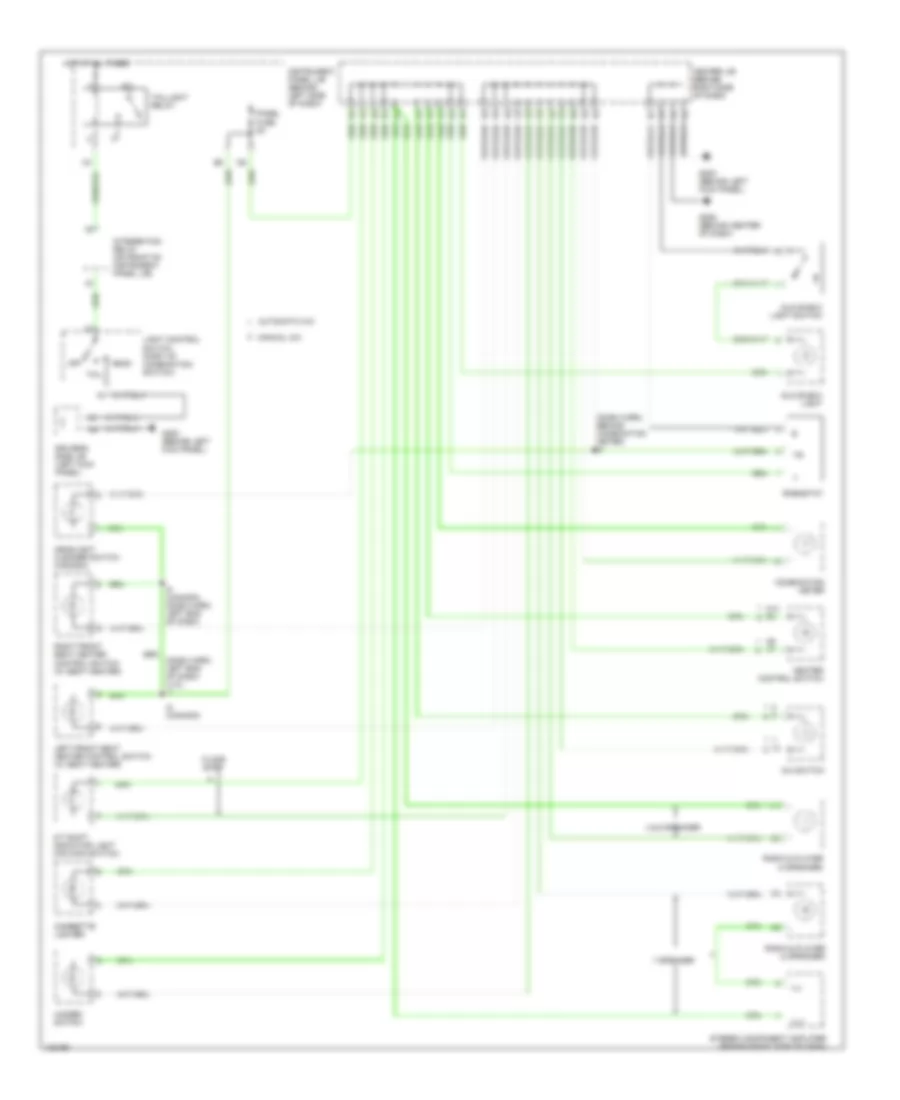
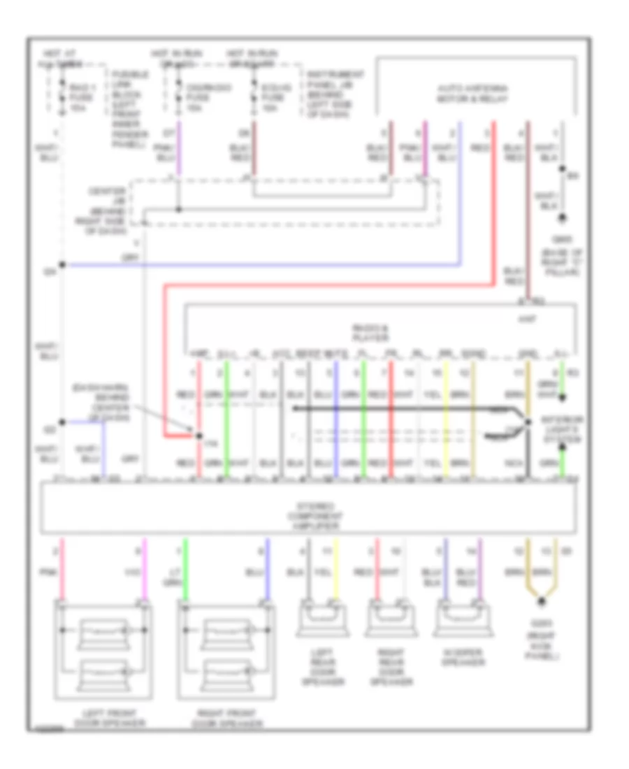
Instrument Illumination Wiring Diagram for Toyota Avalon XLS 1999
List of elements for Instrument Illumination Wiring Diagram for Toyota Avalon XLS 1999:
- (dash harn, behind combination meter) i8
- (dash harn, left end of dash) (u.s.) i4
- 4 & 6 speaker
- 7 speaker
- A/c switch
- A/t shift indicator light (o/d main switch)
- A10
- A14 b6
- A6 a7
- Automatic a/c
- Center j/b (behind right side of dash)
- Cigarette lighter
- Combination meter
- Driver's side j/b (left kick panel)
- Floor shift
- G200 (behind left kick panel)
- G206 (behind center of dash)
- Glove box light
- Glove box light switch
- Hazard switch
- Head
- Headlight cleaner switch (canada)
- Heater control switch
- Hot at all times
- I5 (canada)
- I5 (canada) (dash harn, left end of dash)
- Ill+
- Ill-
- Instrument panel j/b (behind left side of dash)
- Integration relay (on front of instrument panel j/b)
- Left front seat heater control switch (w/ seat heater)
- Light control switch (part of combination switch)
- Manual a/c
- Off
- Panel fuse 5a
- Radio & player (4 speaker)
- Rheostat
- Right front seat heater control switch (w/ seat heater)
- Stereo component amplifier (behind right side of dash)
- Tail
- Taillight relay
MEMORY SYSTEMS
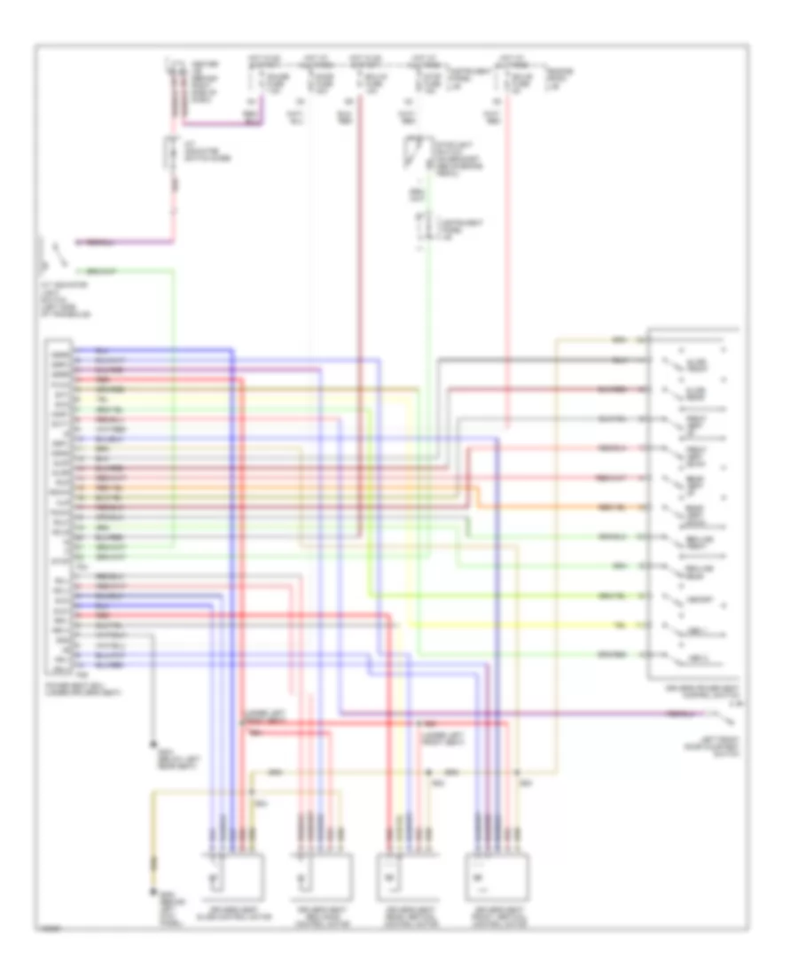
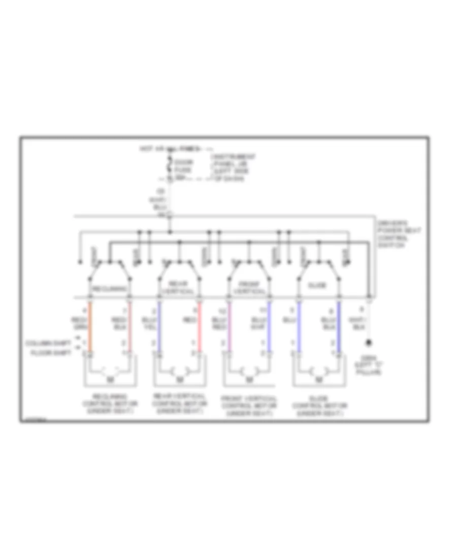
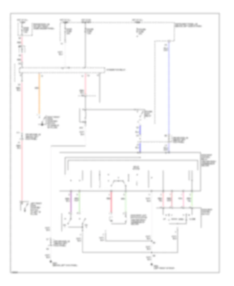
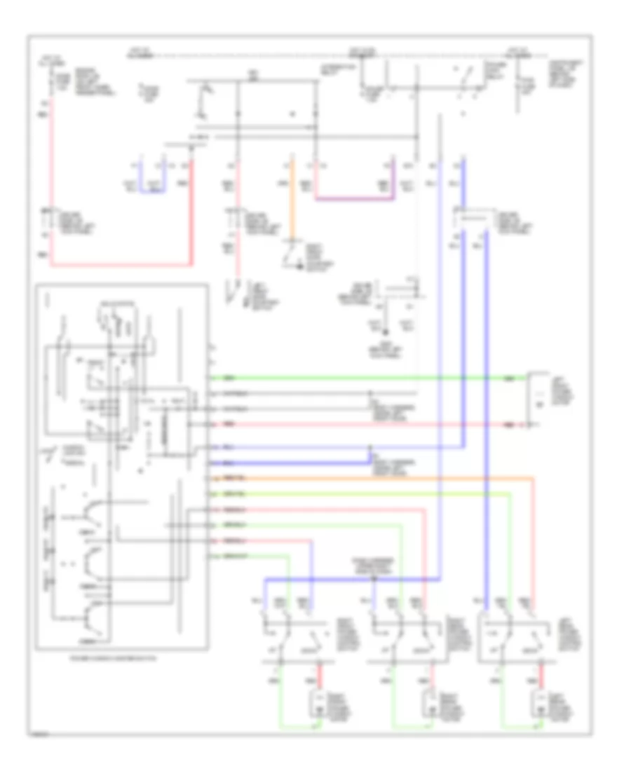
Driver's Memory Seat Wiring Diagram, with Column Shift for Toyota Avalon XLS 1999
List of elements for Driver's Memory Seat Wiring Diagram, with Column Shift for Toyota Avalon XLS 1999:
- (under left front seat)
- A/t indicator light switch (left side of transaxle)
- A/t indicator switch diode
- B23
- B24
- Center j/b (behind right side of dash)
- Dcty
- Door fuse 30a
- Driver's power seat control switch
- Driver's seat front vertical control motor
- Driver's seat rear vertical control motor
- Driver's seat reclining control motor
- Driver's seat slide control motor
- Ecu-b fuse 5a
- Ecu-ig fuse 10a
- Engine room j/b
- Fdwn
- Front vert down
- Front vert up
- Frv+
- Frv-
- Fup
- G200 (behind left kick panel)
- G304 (below left rear seat)
- Gauge fuse 7.5a
- Gnd
- Hot at all times
- Hot in on & start
- Instrument panel j/b
- Left front door courtesy switch
- Mem 1
- Mem 2
- Memory
- Mmry
- P24
- P25
- Power seat ecu (under driver's seat)
- Pvcc
- Rcl+
- Rcl-
- Rclf
- Rclr
- Rdwn
- Rear vert down
- Rear vert up
- Recline front
- Recline rear
- Red
- Rrv+
- Rrv-
- Rup
- Sgnd
- Sld+
- Sld-
- Sldf
- Sldr
- Slide front
- Slide rear
- Ssfv
- Ssrr
- Ssrs
- Ssrv
- Stop
- Stop fuse 15a
- Stoplight switch (on bracket above brake pedal)
- Sw1
- Sw2
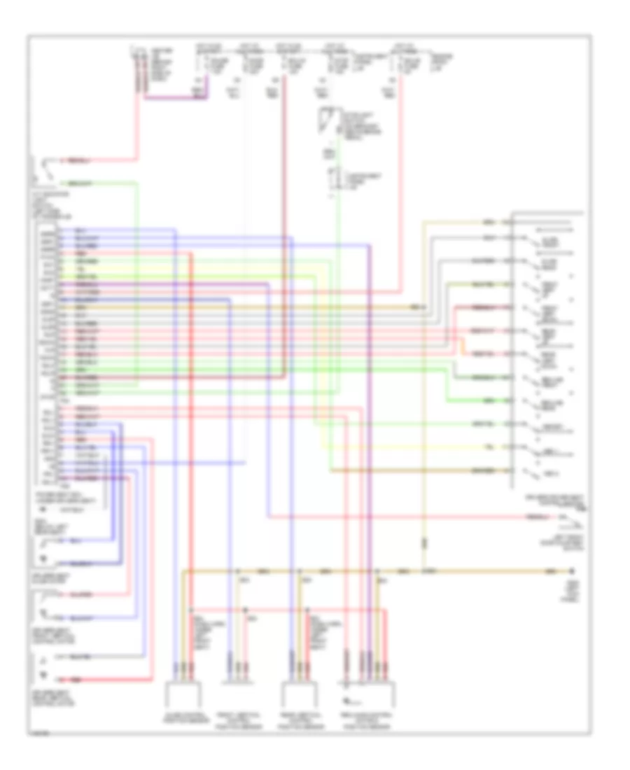
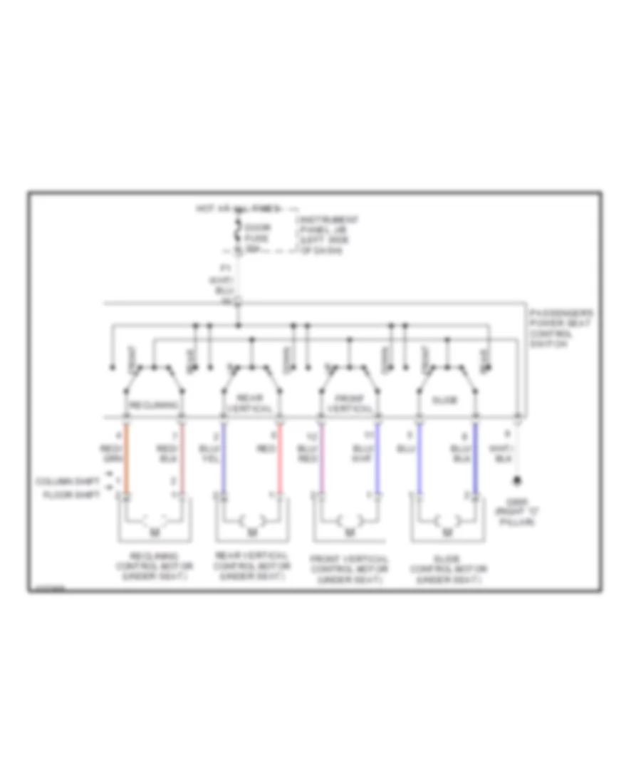
Driver's Memory Seat Wiring Diagram, with Floor Shift for Toyota Avalon XLS 1999
List of elements for Driver's Memory Seat Wiring Diagram, with Floor Shift for Toyota Avalon XLS 1999:
- A/t indicator light switch (left side of transaxle)
- B23
- B23 (dash harn, under left front seat)
- B24
- B24 (dash harn, under left front seat)
- Center j/b (behind right side of dash)
- Dcty
- Door fuse 30a
- Driver's power seat control switch
- Driver's seat front vertical control motor
- Driver's seat rear vertical control motor
- Driver's seat slide motor
- Ecu-b fuse 5a
- Ecu-ig fuse 10a
- Engine room j/b
- Fdwn
- Front vert down
- Front vert up
- Front vertical control position sensor
- Frv+
- Frv-
- Fup
- G200 (left kick panel)
- G304 (below left rear seat)
- Gauge fuse 7.5a
- Gnd
- Hot at all times
- Hot in on & start
- Instrument panel j/b
- Left front door courtesy switch
- Mem 1
- Mem 2
- Memory
- Mmry
- P24
- P25
- Power seat ecu (under driver's seat)
- Pvcc
- Rcl+
- Rcl-
- Rclf
- Rclr
- Rdwn
- Rear vert down
- Rear vert up
- Rear vertical control position sensor
- Recline front
- Recline rear
- Reclining control motor & position sensor
- Red
- Rrv+
- Rrv-
- Rup
- Sgnd
- Sld+
- Sld-
- Sldf
- Sldr
- Slide control position sensor
- Slide front
- Slide rear
- Ssfv
- Ssrr
- Ssrs
- Ssrv
- Stop
- Stop fuse 15a
- Stoplight switch (on bracket above brake pedal)
- Sw1
- Sw2
POWER ANTENNA
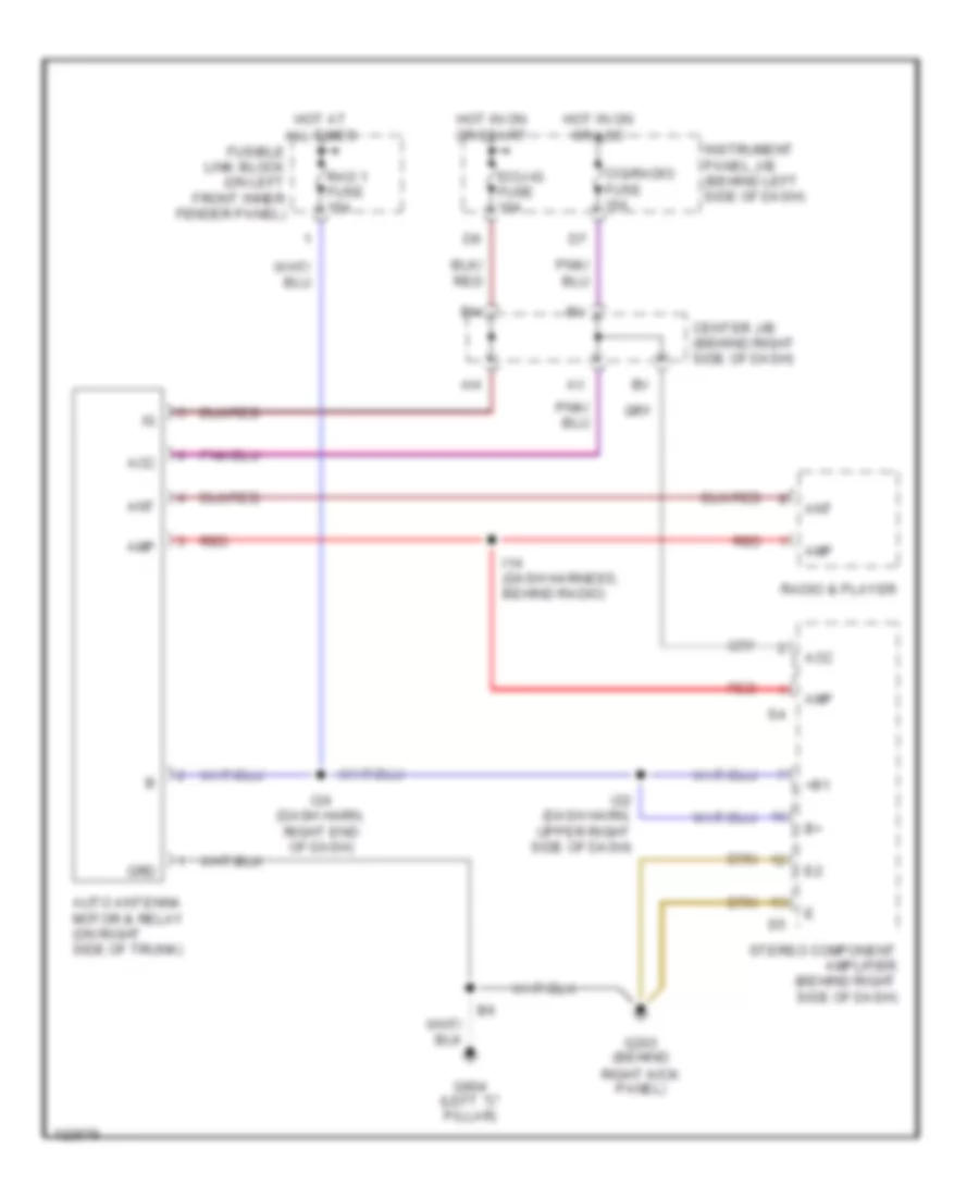
Power Antenna Wiring Diagram for Toyota Avalon XLS 1999
List of elements for Power Antenna Wiring Diagram for Toyota Avalon XLS 1999:
- +b1
- Acc
- Amp
- Ant
- Auto antenna motor & relay (on right side of trunk)
- Center j/b (behind right side of dash)
- Cig/radio fuse 15a
- Ecu-ig fuse 10a
- Fusible link block (on left front inner fender panel)
- G203 (behind right kick panel)
- G904 (left "c" pillar)
- Grd
- Hot at all times
- Hot in on or acc
- Hot in on or start
- I14 (dash harness, behind radio)
- I22 (dash harn, upper right side of dash)
- I24 (dash harn, right end of dash)
- Instrument panel j/b (behind left side of dash)
- Rad 1 fuse 15a
- Radio & player
- Red
- Stereo component amplifier (behind right side of dash)
POWER DISTRIBUTION
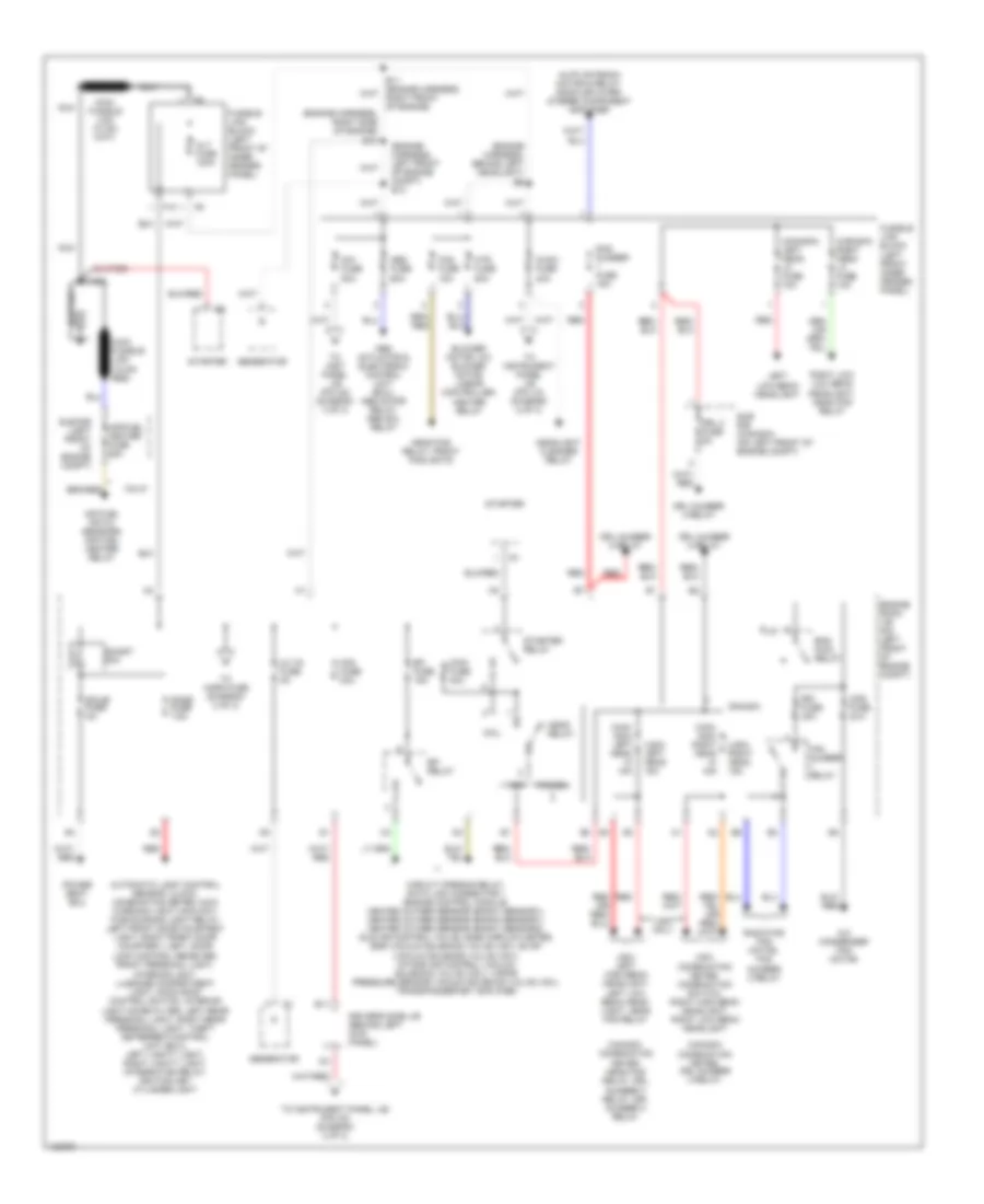
Power Distribution Wiring Diagram (1 of 3) for Toyota Avalon XLS 1999
List of elements for Power Distribution Wiring Diagram (1 of 3) for Toyota Avalon XLS 1999:
- (can- ada) left head hi 15a
- (can- ada) right head hi 15a
- (canada) left head lo fuse 10a
- (canada) right head lo fuse 10a
- (engine harness, behind left headlight) e6
- (engine harness, left front of engine compt) e13
- (engine harness, right side of engine) e10
- (usa) left head 15a
- (usa) right head 15a
- A/c condenser fan motor
- Abs actuator & electronic control unit (ecu), abs motor relay, abs sol relay
- Abs fuse 60a
- Air fuel ratio sensors, air fuel heater relay
- Air/fuel heater fuse 25a
- Alt fuse 120a
- Alt-s fuse 5a
- Am1 fuse 80a
- Am2 fuse 30a
- Auto antenna motor & relay, radio &player, stereo component amplifier
- Automatic light control sensor, clock, combination meter, main warning light, main day- time running light relay, left front door courtesy light, right front door courtesy light, door
- B11
- Battery
- Blower motor, a/c blower motor linear controller,
- Calif.
- Canada
- Canada:
- Canada: combination meter, head fog relay, drl
- Cds fuse 30a
- Circuit opening relay, data link connector 1 engine control module, heated oxygen sensor (bank1 sensor1), heated oxygen sensor (bank2 sensor1), heated oxygen sensor (bank1 sensor2), idle air control valve, mass airflow meter, egr vacuum solenoid valve (vsv), evap vacuum solenoid valve (vsv), intake air control vacuum solenoid valve (vsv), vapor pressure sensor vacuum soleniod valve (vsv), transponder key amplifier
- Coil
- Combination meter, drl number 3 relay,
- Dome fuse 7.5a
- Driver's side j/b (behind left kick panel)
- Drl 2 fuse 5a
- Drl number 2 relay
- Drl number 3 relay
- Ecu-b fuse 5a
- Efi fuse 15a
- Efi relay
- Eng main relay
- Engine room j/b (on left front of engine compt)
- F10
- Fan number relay
- Fog fuse 15a
- Fusible link block (left front inner fender panel)
- Fusible link block (left front of inner fender panel)
- Generator
- Head fog relay, front foglights
- Head relay
- Headlight cleaner relay
- Heater relay
- Htr fuse 50a
- Ig sw fuse 40a
- Left low beam headlight
- Lock control receiver, front personal light, interior light, luggage compartment light, moon roof control switch, interior light noise filter, left rear personal light, right rear personal light, theft deterrent control unit (ecu), left vanity light, right vanity light, integration relay, ignition key cylinder light
- Main fuse 40a
- Main fusible link (18 ga- red)
- Nca
- Number 3 relay, drl number 4 relay
- Power seat ecu
- Rad number fuse 15a
- Radiator fan motor, fan number 3 relay
- Rdi fuse 30a
- Red
- Right low low beam headlight, head fog relay
- Short pin
- Starter
- Starter relay
- Sub r/b (canada) (on left front of engine compt)
- Sub r/b (left front of engine compt)
- To horn fuse (diagram 2 of 3)
- To inst panel j/b (pin a2) (diagram 3 of 3)
- To instrument panel j/b (pin 1a) (diagram 2 of 3)
- To instrument panel j/b (pin a3) (diagram 2 of 3)
- Usa
- Usa only
- Usa: combination meter, combination switch; right high beam headlight, right low beam headlight
- Usa: left high beam headlight, left low beam head- light, head fog relay
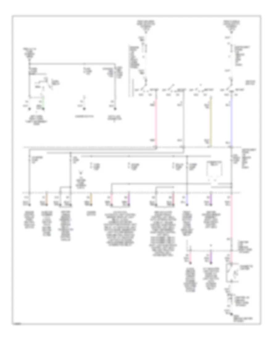
Power Distribution Wiring Diagram (2 of 3) for Toyota Avalon XLS 1999
List of elements for Power Distribution Wiring Diagram (2 of 3) for Toyota Avalon XLS 1999:
- (behind right side of dash)
- (canada) obd fuse 7.5a
- (usa) obd trac fuse 7.5a
- A/c switch, automatic light control sensor, back-up light relay, clock, combination meter, main daytime running light relay, a/t indicator light switch diode, generator, light failure sensor,
- A/t indicator light switch diode. a/t indicator light switch, auto antenna motor & relay
- Abs actuator & electronic control unit (ecu), auto antenna motor & relay, cruise control electronic control unit (ecu), theft deterrent electronic control unit (ecu), fan number 1 relay, fan number 2 relay, fan number 3 relay, shift lock electronic control unit (ecu), abs and traction control ecu, power seat ecu
- Acc
- Center air bag sensor assembly, shift lock electronic control unit (ecu)
- Center airbag sensor assembly, circuit opening relay, combination meter, engine control module
- Center j/b
- Center j/b (behind right side of dash)
- Cig/ radio fuse 15a
- Cigarette lighter
- Clock, remote control mirror switch, stereo component amplifier, radio & player
- Coil
- D10
- Data link connector
- Ecu-ig fuse 10a
- Engine control module, park/ neutral position switch
- Engine room j/b (on left front inner fender panel)
- F12
- From alt-s fuse (diagram 1 of 3)
- From driver's side j/b (pin d4) (diagram 1 of 2)
- From fusible link block f11 (diagram 1 of 3)
- Front wiper & washer switch, front wiper motor, headlight cleaner relay
- G206 (behind center of dash)
- Gauge fuse 7.5a
- Haz fuse 10a
- Hazard switch
- Horn fuse 10a
- Horn relay
- Ign fuse 5a
- Igniter, ignition noise filter
- Ignition switch
- Injector numbers 1, 2, 3, 4, 5 & 6, ignition coils
- Instrument panel j/b (behind left side of dash)
- Integration relay
- Left horn, right horn, theft deterrent horn
- Off
- Park/neutral position switch; a/t indicator light switch diode, vehicle speed sensor, integration relay
- Red
- Start
- Starter fuse 5a
- To heater fuse (diagram 3 of 3)
- Turn fuse 7.5a
- Wiper fuse 20a
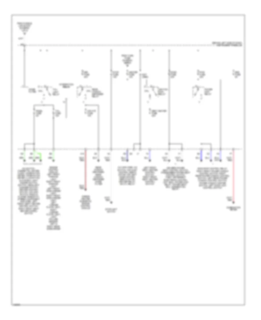
Power Distribution Wiring Diagram (3 of 3) for Toyota Avalon XLS 1999
List of elements for Power Distribution Wiring Diagram (3 of 3) for Toyota Avalon XLS 1999:
- (behind left side of dash) instrument panel j/b
- (not used)
- A/c amplifier, a/c switch, air inlet control servo motor, air vent mode control servo motor, heater relay, mg ctl relay
- A/c switch, cigarette lighter, clock, combination meter, combination meter illumination, glove box light, hazard switch, switch, headlight cleaner switch, heater control switch, o/d main switch, radio & player, rheostat, stereo component amplifier, left front seat heater control switch, right front seat heater conrol switch
- Coil
- Combination meter
- Def fuse 40a
- Door fuse 30a
- Driver's power seat control switch, passenger's power seat control switch, theft deterrent electronic control unit (ecu), power main relay, power seat ecu, integration relay
- Engine control module, left front parking light, right front parking light, left front side marker light, right front side marker light, left license plate light, right license plate light, light failure sensor, left & right rear sidemarker
- From fusible link block (diagram 1 of 3)
- From turn fuse (diagram (2 of 3)
- H10
- Heater fuse 10a
- Ignition main relay
- Integration relay
- Left front seat heater control switch, right front seat heater control switch
- Mir htr fuse 10a
- Mirror heater elements, engine control module
- Moon roof control relay,
- Noise filter
- Panel fuse 5a
- Power main relay
- Pwr fuse 30a
- Rear window defogger relay
- Rear window defogger, rear window defogger noise filter
- Right front power window control switch, right rear power window control switch, left rear power window control switch, power window master switch, left door lock control switch
- Seat heater fuse 20a
- Srs fuse 5a
- Stop fuse 15a
- Stoplight switch
- Tail fuse 15a
- Tail- light relay
POWER DOOR LOCKS
Power Door Lock Wiring Diagram for Toyota Avalon XLS 1999
List of elements for Power Door Lock Wiring Diagram for Toyota Avalon XLS 1999:
- (behind center of dash) g206
- (behind combination meter) i8
- (behind right side of dash) (w/ anti-theft) theft deterrent ecu
- (below left rear seat)
- (left end of dash)
- (right "c" pillar)
- (right end of dash) i24
- B11
- Center j/b (behind right side of dash)
- Dome fuse 7.5a
- Door fuse 30a
- Door lock control receiver (w/ keyless entry) (left side of trunk)
- Driver side j/b (behind left kick panel)
- Ecu-ig fuse 10a
- Engine room j/b (left front inner fender panel)
- G2 red
- G200 (behind left kick panel)
- G206 (behind center of dash)
- G304
- G407 (center rear of trunk)
- G905
- Gauge fuse 7.5a
- H12
- Hot at all times
- Hot in on or start
- Hot in run or start
- I24
- I25
- I31
- Instrument panel j/b (behind left side of dash)
- Integration relay
- J3 red
- Left door key lock/ unlock switch
- Left door lock control switch (power window master switch)
- Left front door lock motor/door unlock detection switch
- Left rear door lock motor/door unlock detection switch
- Lock
- N5 red
- Power fuse 30a
- Power main relay
- Power windows system (power window master switch)
- Red
- Right door key lock/ unlock switch
- Right door lock control switch
- Right front door lock motor/door unlock detection switch
- Right rear door lock motor/door unlock detection switch
- Unlock
- Unlock warning switch (steering column)
POWER MIRRORS
Power Mirror Wiring Diagram for Toyota Avalon XLS 1999
List of elements for Power Mirror Wiring Diagram for Toyota Avalon XLS 1999:
- Center j/b (behind right side of dash)
- Cig/radio fuse 15a
- Defogger system
- Down
- G206 (center of dash)
- Hot in acc or on
- I6 (dash harn, upper left end of dash)
- If equipped
- Instrument panel j/b (behind left side of dash)
- Left
- Left remote control mirror
- Operation switch
- Remote control mirror switch
- Right
- Right remote control mirror
- Select switch
POWER SEATS
Driver Power Seat Wiring Diagram for Toyota Avalon XLS 1999
List of elements for Driver Power Seat Wiring Diagram for Toyota Avalon XLS 1999:
- Column shift
- Door fuse 30a
- Down
- Driver's power seat control switch
- Floor shift
- Front
- Front vertical
- Front vertical control motor (under seat)
- G904 (left "c" pillar)
- Hot at all times
- Instrument panel j/b (left side of dash)
- Rear
- Rear vertical
- Rear vertical control motor (under seat)
- Reclining
- Reclining control motor (under seat)
- Red
- Slide
- Slide control motor (under seat)
Heated Seats Wiring Diagram for Toyota Avalon XLS 1999
List of elements for Heated Seats Wiring Diagram for Toyota Avalon XLS 1999:
- Driver side j/b (behind left kick panel)
- Driver's seat heater (for seat cushion)
- Driver's seat heater (for seatback)
- Driver's seat heater control switch
- G200 (behind left kick panel)
- G203 (behind right kick panel)
- G304 (below left rear seat)
- G905 (right "c" pillar)
- Hot in on or start
- I8 (dash harness, behind combination meter)
- Instrument panel j/b (left side of dash)
- Pass seat heater (for seat cushion)
- Passenger's seat heater (for seatback)
- Passenger's seat heater control switch
- Seat-htr fuse 20a
Passenger Power Seat Wiring Diagram for Toyota Avalon XLS 1999
List of elements for Passenger Power Seat Wiring Diagram for Toyota Avalon XLS 1999:
- Column shift
- Door fuse 30a
- Down
- Floor shift
- Front
- Front vertical
- Front vertical control motor (under seat)
- G905 (right "c" pillar)
- Hot at all times
- Instrument panel j/b (left side of dash)
- Passenger's power seat control switch
- Rear
- Rear vertical
- Rear vertical control motor (under seat)
- Reclining
- Reclining control motor (under seat)
- Red
- Slide
- Slide control motor (under seat)
POWER TOP/SUNROOF
Power Top/Sunroof Wiring Diagrams for Toyota Avalon XLS 1999
List of elements for Power Top/Sunroof Wiring Diagrams for Toyota Avalon XLS 1999:
- (center front underside of ceiling)
- Close
- Dome fuse 7.5a
- Door fuse 30a
- Down
- Driver side j/b (behind left kick panel)
- E10
- Engine room j/b (on left front inner fender panel)
- F11
- G200 (behind left kick panel)
- G902 (left front of roof)
- Gauge fuse 7.5a
- Hot at all times
- Hot in on or start
- I18
- Instrument panel j/b (behind left side of dash)
- Integration relay
- Left front door courtesy switch (in left "b" pillar)
- Moon roof control relay (center front underside of ceiling)
- Moon roof control switch
- Moon roof limit switch & motor
- No.
- Open
- Pnk
- Power fuse 30a
- Power main relay
- Red
- Right front door courtesy switch (at base of "b" pillar)
- Solid state
POWER WINDOWS
Power Window Wiring Diagram for Toyota Avalon XLS 1999
List of elements for Power Window Wiring Diagram for Toyota Avalon XLS 1999:
- (dash harness, upper right side of dash) i22
- Auto
- B1 (body harness, inside left front door)
- Dome fuse 7.5a
- Door fuse 30a
- Door lock
- Down
- Driver side j/b (behind left kick panel)
- E10
- Engine room j/b (on left front inner fender panel)
- F11
- Front lt
- Front rt
- G200 (behind left kick panel)
- Gauge fuse 7.5a
- Hot at all times
- Hot in on or start
- I18
- Iinstrument panel j/b (behind left side of dash)
- Integration relay
- Key off
- Left front door courtesy switch
- Left front power window motor
- Left rear power window control switch
- Left rear power window motor
- Lock
- Normal
- Power main relay
- Power window master switch
- Pwr fuse 30a
- Rear lt
- Rear rt
- Red
- Right front door courtesy switch
- Right front power window control switch
- Right front power window motor
- Right rear power window control switch
- Right rear power window motor
- Solid state
- Window lock sw
RADIO
Radio Wiring Diagrams, with Amplifier for Toyota Avalon XLS 1999
List of elements for Radio Wiring Diagrams, with Amplifier for Toyota Avalon XLS 1999:
- (base of right "c" pillar)
- (dash harn, behind center of dash)
- (right kick panel)
- Acc
- Amp
- Ant
- Auto antenna motor & relay
- Beep
- Center j/b (behind right side of dash)
- Cig/radio fuse 15a
- Ecu-ig fuse 10a
- Fusible link block (left front inner fender panel)
- G203
- G905
- Gnd
- Hot at all times
- Hot in run or acc
- Hot in run or start
- I14
- I14 nca
- I22
- I24
- Ill+
- Ill-
- Instrument panel j/b (behind left side of dash)
- Interior lights system
- Left front door speaker
- Left rear door speaker
- Mute
- Nca
- Pnk
- Rad 1 fuse 15a
- Radio & player
- Red
- Right front door speaker
- Right rear door speaker
- Sgnd
- Stereo component amplifier
- Woofer speaker
Radio Wiring Diagrams, without Amplifier for Toyota Avalon XLS 1999
List of elements for Radio Wiring Diagrams, without Amplifier for Toyota Avalon XLS 1999:
- (right kick panel)
- Center j/b (behind right side of dash)
- Cig/radio fuse 15a
- Fusible link block (left front inner fender panel)
- G203
- Hot at all times
- Hot in run or acc
- Instrument panel j/b (behind left side of dash)
- Interior lights system
- Left front door speaker
- Left rear door speaker
- Pnk
- Rad 1 fuse 15a
- Radio & player
- Red
- Right front door speaker
- Right rear door speaker
- W/ 6 speakers
SHIFT INTERLOCKS
Shift Interlock Wiring Diagram for Toyota Avalon XLS 1999
List of elements for Shift Interlock Wiring Diagram for Toyota Avalon XLS 1999:
- (behind ign key cylinder)
- Acc
- Center j/b (right side of dash)
- Cig & rad fuse 15a
- Dash j/b (left side of dash)
- Driver side j/b (left kick panel)
- E10
- Ecu-ig fuse 10a
- G200 (left kick panel)
- G206 (center of dash)
- Hot at all times
- Hot in acc or on
- Hot in on or start
- Instrument panel j/b (left side of dash)
- Key interlock solenoid
- Kls+
- Shift lock control switch
- Shift lock ecu (column shift: on underside of steering column console shift: below center console)
- Shift lock solenoid
- Sls+
- Sls-
- Stop fuse 10a
- Stoplight switch (on bracket, above brake pedal)
- Stp
STARTING/CHARGING
Charging Wiring Diagram for Toyota Avalon XLS 1999
List of elements for Charging Wiring Diagram for Toyota Avalon XLS 1999:
- Alt fuse 120a
- Alt-s fuse 5a
- Battery
- Battery ground
- Center j/b (behind right side of dash)
- Charge warning light
- Comb- ination meter
- D10
- Daytime running light relay (main) (canada) (behind left side of dash)
- Engine room j/b (left front inner fender panel)
- Fusible link block (left side of front inner fender panel)
- Gauge fuse 7.5a
- Generator
- Hot at all times
- Hot in on or start
- I13 (dash harness, right side of dash)
- I16 (dash harness, right side of radio)
- Ign fuse 5a
- Instrument panel j/b (behind left side of dash)
- Nca
- Transaxle)
- Vehicle speed sensor (right side of
Starting Wiring Diagram for Toyota Avalon XLS 1999
List of elements for Starting Wiring Diagram for Toyota Avalon XLS 1999:
- Acc
- Alt fuse 120a
- Am2 fuse 30a
- B11
- Battery ground
- Calif, w/ immoblizer and/or traction, except calif
- Driver's side j/b (behind left kick panel)
- E12
- Engine control module (behind right side of dash)
- Engine room j/b (on left front inner fender panel)
- F10
- F12
- Fusible link block (on left front of inner fender panel)
- G203 (behind right kick panel)
- Ignition switch
- Instrument panel j/b (behind left side of dash)
- Main fuse 40a
- Nca
- Off
- Park/neutral position switch (on left side of transaxle)
- Red
- Sta
- Start
- Starter
- Starter fuse 5a
- Starter relay
- W/o immoblizer & traction, except calif & 1999
SUPPLEMENTAL RESTRAINTS
Supplemental Restraint Wiring Diagram for Toyota Avalon XLS 1999
List of elements for Supplemental Restraint Wiring Diagram for Toyota Avalon XLS 1999:
- (behind right side of dash) center j/b
- (dash panel brace) g202
- (left intake manifold) g120
- (partial) (behind left side of dash, on instrument panel j/b)
- (partial) (on right rear corner of engine compartment)
- (right kick panel) g203
- +sl
- +sr
- -sl
- -sr
- A10
- A11
- A12
- A13
- A14
- A15
- A16
- A17
- A18
- A19
- A20
- A21
- A22
- A23
- A24
- A25
- A26
- A27
- A28
- Acc
- Air bag squib (front passenger air bag assembly)
- Air bag squib (steering wheel pad)
- B10
- B11
- B12
- C10
- C11
- C12
- C16
- C17
- C18
- Center air bag sensor assembly (column shift- between front seats) (console shift) (below rear of center console)
- Cig/radio fuse 15a
- Combination meter
- Data link connector (dlc) 3 (partial) (behind left side of dash, on instrument panel j/b)
- Data link connector 1 (dlc)
- Data link connector 2 (dlc)
- Driver side j/b (behind left kick panel)
- Esl
- Esr
- Fsl
- Fsr
- Hot at all times
- Hot in acc or on
- Hot in on or start
- Ig2
- Ign fuse 5a
- Instrument panel j/b (behind left side of dash)
- J/c 2 (behind right center of dash)
- J/c 4 (behind right center of dash)
- Left air bag sensor (left front of vehicle)
- Left pretensioner (at bottom of left "b" pillar)
- Left side air bag sensor (at bottom of left "b" pillar)
- Left side air bag squib
- Pl+
- Pl-
- Pnk
- Pr+
- Pr-
- Right air bag sensor (right front of vehicle)
- Right pretensioner (at bottom of right "b" pillar)
- Right side air bag sensor (if equipped) (at bottom of right "b" pillar)
- Right side air bag squib
- Sfl+
- Sfl-
- Sfr+
- Sfr-
- Shield
- Sil
- Spiral cable
- Srs fuse 5a
- Srs warning indicator
- Ssl+
- Ssr+
- Vupl
- Vupr
TRANSMISSION
A/T Wiring Diagram for Toyota Avalon XLS 1999
List of elements for A/T Wiring Diagram for Toyota Avalon XLS 1999:
- "2" indic
- "d" indic
- "l" indic
- "n" indic
- "p" indic
- "r" indic
- (cali)
- (ctr of dash) i18 (floor shift) i20 (column shift)
- (dash harn, floor shift: right side of dash, column shift: center of dash)
- (dash harn, right center of dash)
- (dash harn, right side of dash)
- (dash harn, right side of radio)
- (right side of dash) i18 (floor shift) i19 (column shift)
- Auto a/c
- Batt
- Cali
- Center j/b (behind right side of dash)
- Center j/b (right side of dash)
- Cig/radio fuse 15a
- Clock
- Column shift
- Cruise control module (behind right side of dash)
- D10
- Data link connector 1 (right rear of corner engine compt)
- Diode (behind right center of dash, taped to harness)
- Driver side j/b (behind left kick panel)
- E10
- E10 (eng harn, right side of eng)
- E11
- E12
- Efi fuse 15a
- Efi relay
- Electronically controlled transmission pattern select switch
- Electronically controlled transmission solenoid
- Engine control module (behind right side of dash)
- Engine controls
- Engine controls system (a/f htr relay)
- Engine coolant
- Engine room j/b (left front inner fender panel)
- Eo1
- Eo2
- Eo3
- Eo4
- F12
- Floor shift
- G131 (right side of intake manifold)
- G206 (instrument panel brace)
- G305 (behind right "b" pillar)
- Gauge fuse 7.5a
- Hot at all times
- Hot in on or acc
- Hot in on or start
- Hot in start
- I16
- I16 (dash harn, right center of dash)
- I17
- I19/i12
- Idlo
- Ign fuse 5a
- Igsw
- Instrument cluster (speedometer)
- Instrument panel j/b (behind left side of dash)
- J2 junction connector
- Manual a/c
- Mrel
- Nc2+
- Nc2-
- O/d direct clutch speed sensor (top of transaxle)
- O/d main switch (flr shft- below ctr console) (dash shft- center of dash)
- O/d off indic
- Od1
- Od2
- Park/neutral position switch (on left side of transaxle)
- Pnk
- Power ind light
- Pwr
- Red
- Sensor (on right side of transaxle)
- Sln+
- Snl
- Spd
- Starter fuse 5a
- Starting/ charging
- Stop fuse 15a
- Stop light switch (on bracket, above brake pedal)
- Stp
- Te1
- Temperature sensor (on water outlet)
- Throttle position sensor (on throttle body)
- Thw
- Vehicle speed
- Vta
TRUNK, TAILGATE, FUEL DOOR
Trunk, Tailgate, Fuel Door Wiring Diagrams for Toyota Avalon XLS 1999
List of elements for Trunk, Tailgate, Fuel Door Wiring Diagrams for Toyota Avalon XLS 1999:
- (1998)
- (1999)
- Center j/b (behind right side of dash)
- G206 (behind center of dash)
- G304 (below left rear seat)
- I18
- I24 (dash harness, left end of dash)
- I24 (dash harness, right end of dash)
- Integration relay
- Lug
- Luggage compartment door opener motor (middle rear of trunk lid)
- Luggage compartment door opener switch (right side of dash)
- Luggage compartment key unlock switch
- Theft deterrent ecu (behind right side of dash)
- Tsw
- Xls grade only
WARNING SYSTEMS
Warning System Wiring Diagrams for Toyota Avalon XLS 1999
List of elements for Warning System Wiring Diagrams for Toyota Avalon XLS 1999:
- Buzzer
- Center j/b (behind right side of dash)
- Combination meter
- Dome fuse 7.5a
- Driver side j/b (left kick panel)
- E10
- Engine room j/b (left front of inner fender panel)
- F10
- F11
- G200 (left kick panel)
- G904 (below left rear seat)
- Gauge fuse 7.5a
- Hot at all times
- Hot in on or start
- Ignition switch
- Instrument panel j/b (left side of dash)
- Integration
- Left buckle switch
- Left front door courtesy switch (in left "b" pillar)
- Red
- Relay
- Seat belt ind
- Unlock warning switch
WIPER/WASHER
Wiper/Washer Wiring Diagram for Toyota Avalon XLS 1999
List of elements for Wiper/Washer Wiring Diagram for Toyota Avalon XLS 1999:
- Combination switch
- Driver side j/b (behind left kick panel)
- Front wiper & washer switch
- Front wiper motor (right side of firewall)
- G200 (behind left kick panel)
- G203 (behind right kick panel)
- Hot in on or start
- I12
- Instrument panel j/b (behind left side of dash)
- Int
- Int lo
- L12
- Mist
- Off
- Solid state
- Wash
- Washer motor (in washer fluid reservoir)
- Wiper fuse 20a

 Čeština
 Dansk
Dansk Deutsch
 Ελληνικά
 English
 English
 Español
 Français
 Français
 עברית
עברית Hrvatski
 Magyar
 Italiano
 日本語
日本語 한국어
한국어 Nederlands
 Polski
 Português
 Português
 Română
 Русский
 Slovenčina
 Slovenščina
 Svenska
 Türkçe
 中文 (中国)