AIR CONDITIONING
2.2L
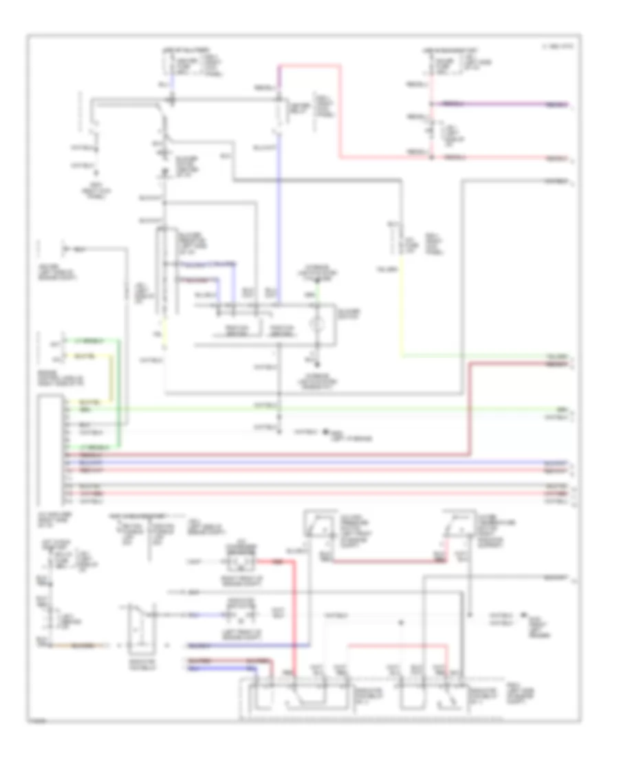
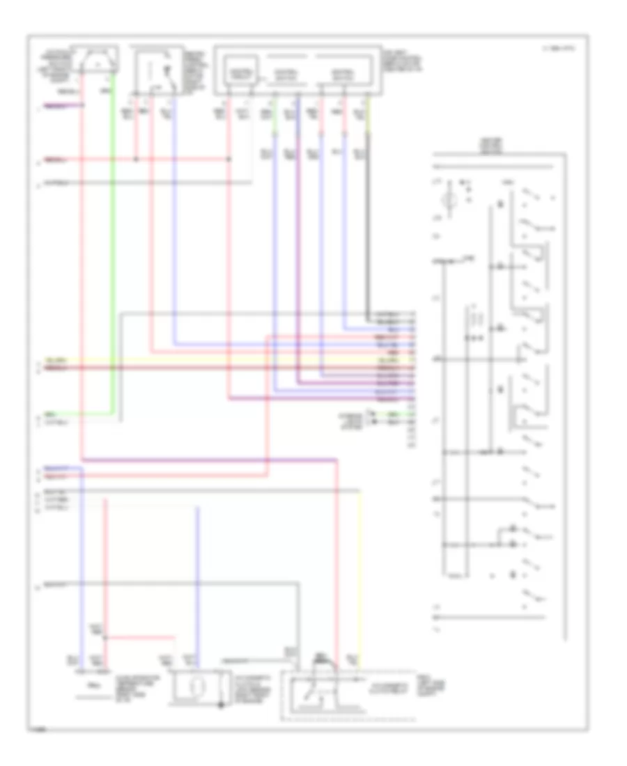
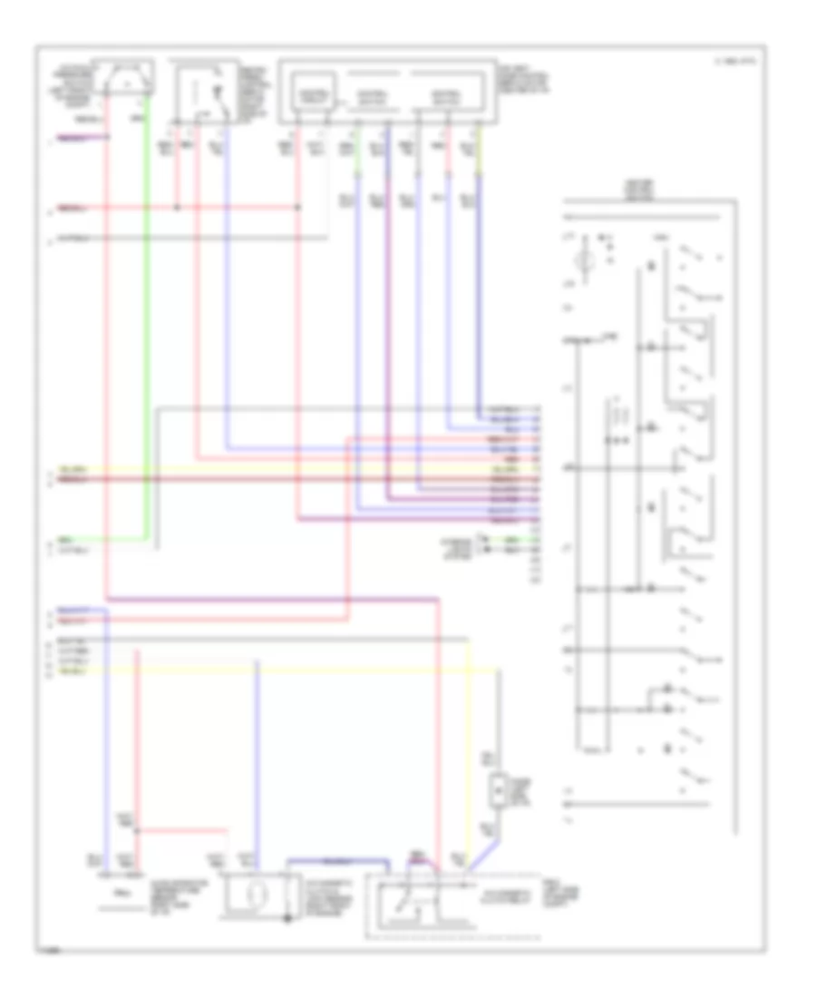
2.2L, A/C Wiring Diagram, Lever Control Type for Toyota Camry XLE 1995
 https://portal-diagnostov.com/license.html
Automotive Electricians Portal FZCO
Automotive Electricians Portal FZCO
https://portal-diagnostov.com/license.html
https://portal-diagnostov.com/license.html
Automotive Electricians Portal FZCO
Automotive Electricians Portal FZCO
List of elements for 2.2L, A/C Wiring Diagram, Lever Control Type for Toyota Camry XLE 1995:
- (left front of engine compt)
- (right front of engine compt)
- 1994 vftc c
- A/c
- A/c amplifier (right side of i/p)
- A/c condenser fan motor
- A/c dual pressure switch (left front of engine compt)
- A/c evaporator temperature sensor (right side of i/p)
- A/c fuse 10a
- A/c high pressure switch (left front of engine compt)
- A/c magnetic clutch & lock sensor (right front of engine)
- A/c magnetic clutch relay
- A/c switch (center of i/p)
- A15
- Act
- Air vent mode control servo motor (center of i/p)
- Air vent mode control switch (center of i/p)
- B/l
- Blower motor (center of i/p)
- Blower resistor (left side of i/p)
- Blower switch
- Cds fan fusible link 30a
- Control circuit
- Control switch
- D12
- Def
- Ecu-ig fuse 15a
- Engine control module (right side of i/p)
- F/d
- Face
- Foot
- G100 (front left fender)
- G202 (left i/p brace)
- G203 (right kick panel)
- Gauge fuse 10a
- Heater fuse 40a
- Heater relay
- Hot at all times
- Hot in run or start
- Igniter (left side of engine compt)
- Interior lights system (rheostat)
- Interior lights system (tail fuse)
- J/b 1 (left side of i/p)
- J/b 2 (left side of engine compt)
- J/b 3 (behind i/p)
- J/c 1 (left side of i/p)
- Off
- R/b 4 (right kick panel)
- R/b 5 (left side of engine compt)
- Radiator fan motor
- Radiator fan relay
- Radiator fan relay n0. 3
- Radiator fan relay no. 2
- Rdi fan fusible link 30a
- Red
- Water temperature switch (right radiator support)
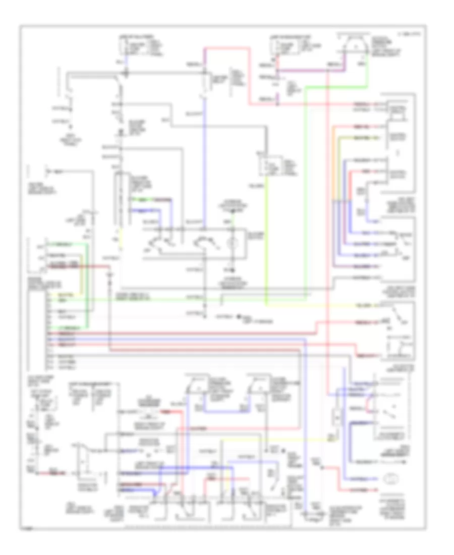
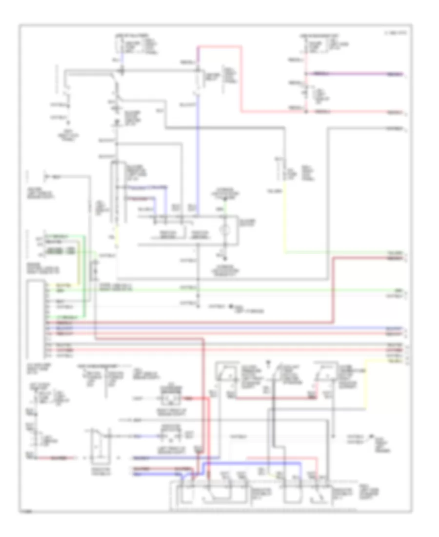
2.2L, A/C Wiring Diagram, Push Control Type (1 of 2) for Toyota Camry XLE 1995
List of elements for 2.2L, A/C Wiring Diagram, Push Control Type (1 of 2) for Toyota Camry XLE 1995:
- (left front of engine compt)
- (right front of engine compt)
- 1994 vftc c
- A/c
- A/c amplifer (right side of i/p)
- A/c condenser fan motor
- A/c fuse 10a
- A/c high pressure switch (left front of engine compt)
- Act
- Blower motor (center of i/p)
- Blower resistor (left side of i/p)
- Blower switch
- Cds fan fusible link 30a
- Ecu-ig fuse 15a
- Engine control module (right side of i/p)
- G100 (front left fender)
- G202 (left i/p brace)
- G203 (right kick panel)
- Gauge fuse 10a
- Heater fuse 40a
- Heater relay
- Hot at all times
- Hot in run or start
- Igniter (left side of engine compt)
- Interior lights system (rheostat)
- Interior lights system (tail fuse)
- J/b 1 (left side of i/p)
- J/b 2 (left side of engine compt)
- J/b 3 (behind i/p)
- Position switch
- R/b 4 (right kick panel)
- R/b 5 (left side of engine compt)
- Radiator fan motor
- Radiator fan relay
- Radiator fan relay n0. 2
- Radiator fan relay n0. 3
- Rdi fan fusible link 30a
- Red
- Water temperature switch (right radiator support)
2.2L, A/C Wiring Diagram, Push Control Type (2 of 2) for Toyota Camry XLE 1995
List of elements for 2.2L, A/C Wiring Diagram, Push Control Type (2 of 2) for Toyota Camry XLE 1995:
- 1994 vftc c
- A/c dual pressure switch (left front of engine compt)
- A/c evaporator temperature sensor (right side of i/p)
- A/c magnetic clutch & lock sensor (right front of engine)
- A/c magnetic clutch relay
- Air vent mode control servo motor (center of i/p)
- Control circuit
- Control switch
- Heater control switch
- Interior lights system
- R/b 5 (left side of engine compt)
- Recirc/ fresh control servo motor (right side of i/p)
- Red
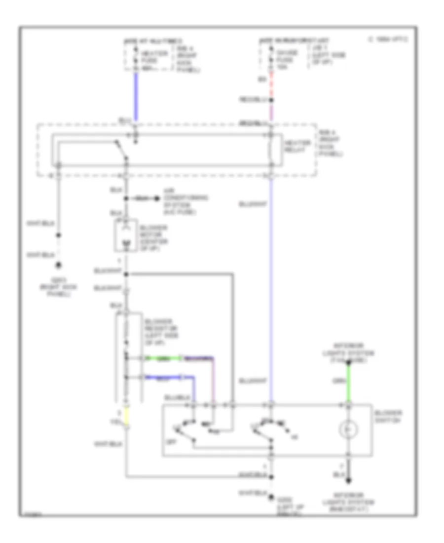
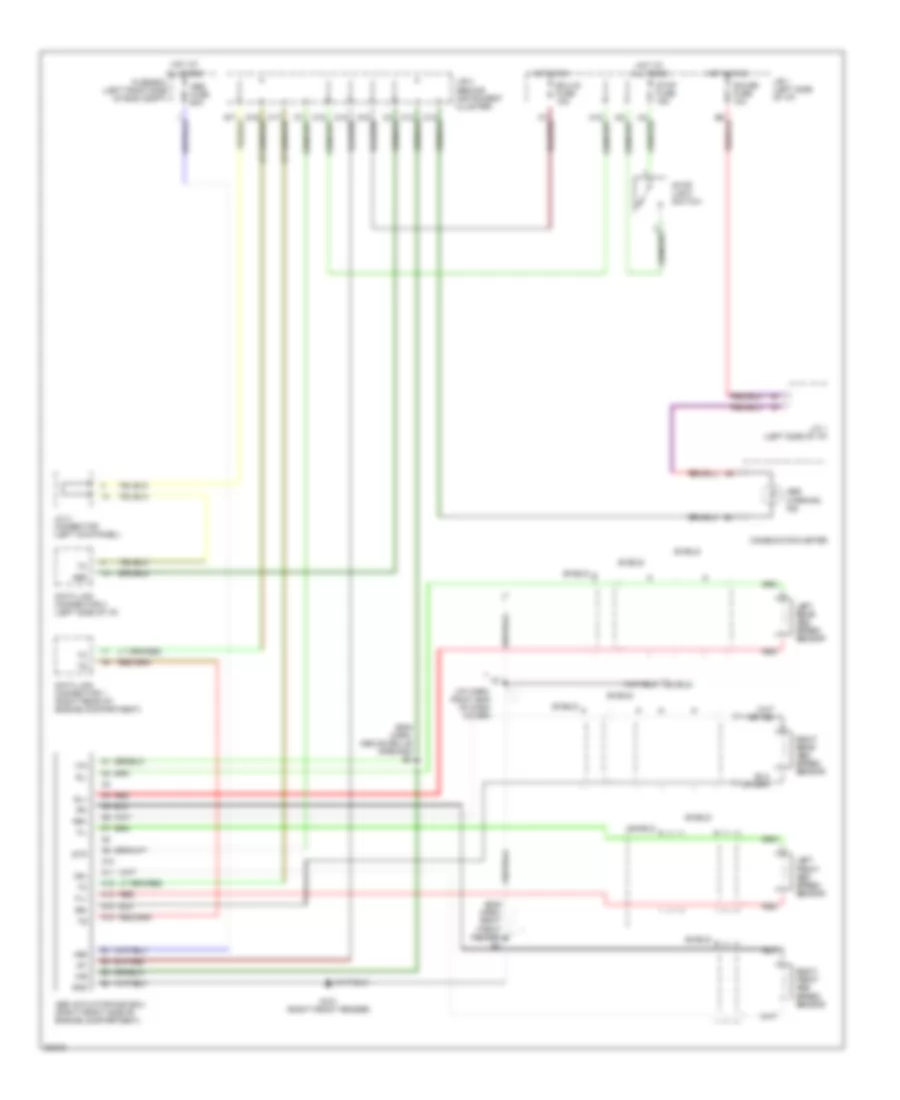
Heater Wiring Diagram, Lever Control Type for Toyota Camry XLE 1995
List of elements for Heater Wiring Diagram, Lever Control Type for Toyota Camry XLE 1995:
- 1994 vftc c
- Air conditioning system (a/c fuse)
- Blower motor (center of i/p)
- Blower resistor (left side of i/p)
- Blower switch
- G202 (left i/p brace)
- G203 (right kick panel)
- Gauge fuse 10a
- Heater fuse 40a
- Heater relay
- Hot at all times
- Hot in run or start
- Interior lights system (rheostat)
- Interior lights system (tail fuse)
- J/b 1 (left side of i/p)
- Off
- R/b 4 (right kick panel)
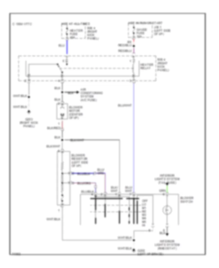
Heater Wiring Diagram, Push Control Type for Toyota Camry XLE 1995
List of elements for Heater Wiring Diagram, Push Control Type for Toyota Camry XLE 1995:
- 1994 vftc c
- Air conditioning system (a/c fuse)
- Blower motor (center of i/p)
- Blower resistor (left side of i/p)
- Blower switch
- G202 (left i/p brace)
- G203 (right kick panel)
- Gauge fuse 10a
- Heater fuse 40a
- Heater relay
- Hot at all times
- Hot in run or start
- Interior lights system (rheostat)
- Interior lights system (tail fuse)
- J/b 1 (left side of i/p)
- Off lo m1 m2 m3 m4 m5 hi
- R/b 4 (right kick panel)
3.0L
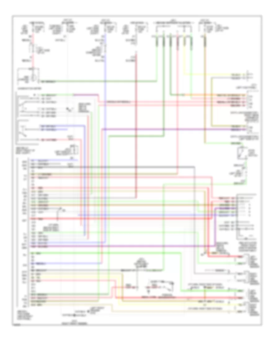
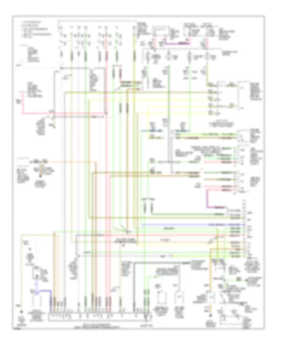
3.0L, A/C Wiring Diagram, Lever Control Type for Toyota Camry XLE 1995
List of elements for 3.0L, A/C Wiring Diagram, Lever Control Type for Toyota Camry XLE 1995:
- (1995 only)
- (1996) (1995)
- (left front of engine compt)
- (right front of engine compt)
- 1994 vftc c
- A/c
- A/c amplifier (right side of i/p)
- A/c condenser fan motor
- A/c dual pressure switch (left front of engine compt)
- A/c evaporator temperature sensor (right side of i/p)
- A/c fuse 10a
- A/c high pressure switch (left front of engine compt)
- A/c magnetic clutch & lock sensor (right front of engine)
- A/c magnetic clutch relay
- A/c switch (center of i/p)
- A15
- Act
- Air vent mode control servo motor (center of i/p)
- Air vent mode control switch (center of i/p)
- B/l
- Blower motor (center of i/p)
- Blower resistor (left side of i/p)
- Blower switch
- Cds fan fusible link 30a
- Control circuit
- Control switch
- Coolant temp switch (center of engine)
- D12
- Def
- Diode (right side of i/p)
- Ecu-ig fuse 15a
- Engine control module (right side of i/p)
- F/d
- Face
- Foot
- G100 (front left fender)
- G202 (left i/p brace)
- G203 (right kick panel)
- Gauge fuse 10a
- Heater fuse 40a
- Heater relay
- Hot at all times
- Hot in run or start
- Igniter (left side of engine compt)
- Interior lights system (rheostat)
- Interior lights system (tail fuse)
- J/b 1 (left side of i/p)
- J/b 2 (left side of engine compt)
- J/b 3 (behind i/p)
- J/c 1 (left side of i/p)
- Off
- R/b 4 (right kick panel)
- R/b 5 (left side of engine compt)
- Radiator fan motor
- Radiator fan relay
- Radiator fan relay n0. 3
- Radiator fan relay no. 2
- Rdi fan fusible link 30a
- Red
- Water temperature switch (right radiator support)
3.0L, A/C Wiring Diagram, Push Control Type (1 of 2) for Toyota Camry XLE 1995
List of elements for 3.0L, A/C Wiring Diagram, Push Control Type (1 of 2) for Toyota Camry XLE 1995:
- (1995 only)
- (1995) (1996)
- (left front of engine compt)
- (right front of engine compt)
- 1994 vftc c
- A/c
- A/c amplifer (right side of i/p)
- A/c condenser fan motor
- A/c fuse 10a
- A/c high pressure switch (left front of engine compt)
- Act
- Blower motor (center of i/p)
- Blower resistor (left side of i/p)
- Blower switch
- Cds fan fusible link 30a
- Coolant temp switch (center of engine)
- Diode (right side of i/p)
- Ecu-ig fuse 15a
- Engine control module (right side of i/p)
- G100 (front left fender)
- G202 (left i/p brace)
- G203 (right kick panel)
- Gauge fuse 10a
- Heater fuse 40a
- Heater relay
- Hot at all times
- Hot in run or start
- Igniter (left side of engine compt)
- Interior lights system (rheostat)
- Interior lights system (tail fuse)
- J/b 1 (left side of i/p)
- J/b 2 (left side of engine compt)
- J/b 3 (behind i/p)
- Position switch
- R/b 4 (right kick panel)
- R/b 5 (left side of engine compt)
- Radiator fan motor
- Radiator fan relay
- Radiator fan relay n0. 2
- Radiator fan relay n0. 3
- Rdi fan fusible link 30a
- Red
- Water temperature switch (right radiator support)
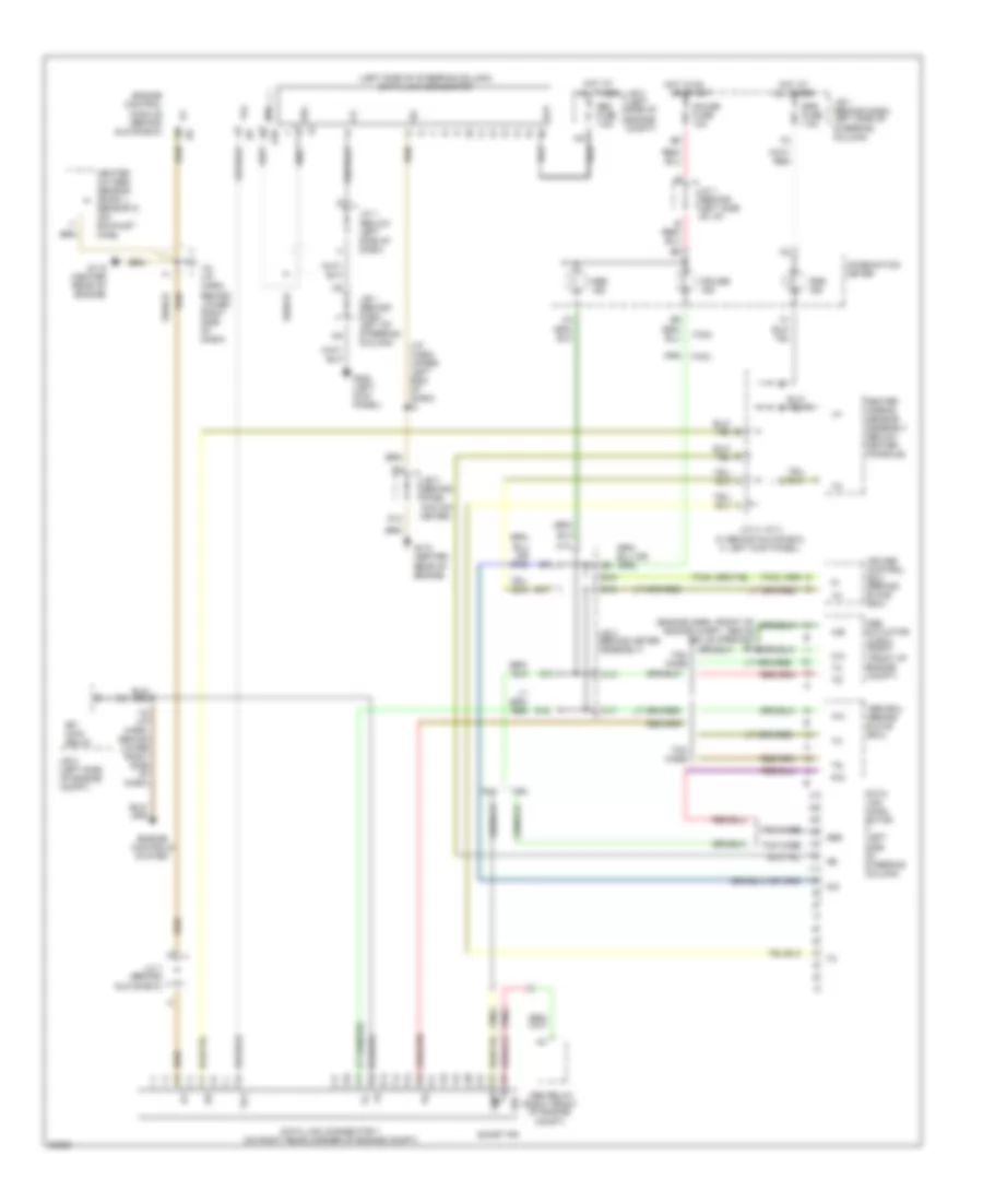
3.0L, A/C Wiring Diagram, Push Control Type (2 of 2) for Toyota Camry XLE 1995
List of elements for 3.0L, A/C Wiring Diagram, Push Control Type (2 of 2) for Toyota Camry XLE 1995:
- 1994 vftc c
- A/c dual pressure switch (left front of engine compt)
- A/c evaporator temperature sensor (right side of i/p)
- A/c magnetic clutch & lock sensor (right front of engine)
- A/c magnetic clutch relay
- Air vent mode control servo motor (center of i/p)
- Control circuit
- Control switch
- Diode (left side of i/p)
- Heater control switch
- Interior lights system
- R/b 5 (left side of engine compt)
- Recirc/ fresh control servo motor (right side of i/p)
- Red
Heater Wiring Diagram, Lever Control Type for Toyota Camry XLE 1995
List of elements for Heater Wiring Diagram, Lever Control Type for Toyota Camry XLE 1995:
- 1994 vftc c
- Air conditioning system (a/c fuse)
- Blower motor (center of i/p)
- Blower resistor (left side of i/p)
- Blower switch
- G202 (left i/p brace)
- G203 (right kick panel)
- Gauge fuse 10a
- Heater fuse 40a
- Heater relay
- Hot at all times
- Hot in run or start
- Interior lights system (rheostat)
- Interior lights system (tail fuse)
- J/b 1 (left side of i/p)
- Off
- R/b 4 (right kick panel)
Heater Wiring Diagram, Push Control Type for Toyota Camry XLE 1995
List of elements for Heater Wiring Diagram, Push Control Type for Toyota Camry XLE 1995:
- 1994 vftc c
- Air conditioning system (a/c fuse)
- Blower motor (center of i/p)
- Blower resistor (left side of i/p)
- Blower switch
- G202 (left i/p brace)
- G203 (right kick panel)
- Gauge fuse 10a
- Heater fuse 40a
- Heater relay
- Hot at all times
- Hot in run or start
- Interior lights system (rheostat)
- Interior lights system (tail fuse)
- J/b 1 (left side of i/p)
- Off lo m1 m2 m3 m4 m5 hi
- R/b 4 (right kick panel)
ANTI-LOCK BRAKES
Anti-lock Brake Wiring Diagrams, TMC Made for Toyota Camry XLE 1995
List of elements for Anti-lock Brake Wiring Diagrams, TMC Made for Toyota Camry XLE 1995:
- (eng harn, above grille opening)
- (i/p harn, behind right side of dash)
- (i/p harn, right end of dash)
- (left front fender) g100
- A10
- A11
- A12
- A13
- A14
- A15
- A16
- A17
- A18
- A19
- A20
- A21
- A22
- A23
- A24
- A25
- A26
- Abs actuator (front right side of engine compartment)
- Abs ecu (tmc made) (above right kick panel)
- Abs fuse 60a
- Abs relay (right front of eng. compt.)
- Abs warning ind
- Ast
- B10
- B11
- B12
- B13
- B14
- B15
- B16
- Bat
- C15
- C16
- C19
- Combination meter
- D/g
- Data link connector 1 (right rear corner of eng compt)
- Data link connector 2 (left side of i/p)
- Ecu-b fuse 15a
- Ecu-ig fuse 15a
- Fl+
- Fl-
- Fr+
- Fr-
- Fss
- Fuse box (left side of eng compt)
- G101 (right front fender)
- Gauge fuse 10a
- Gnd
- Hot at all times
- Hot in run
- I21
- I25
- Ig1
- J/b 1 (left side of i/p)
- J/b 2 (left side of eng compt)
- J/b 3 (behind combination meter)
- J/b 3 (behind instrument cluster)
- J/b 3 (behind instrumnt cluster)
- J/c 1 (left side of i/p)
- J/c 4 (left kick panel)
- Left front abs speed sensor
- Left rear abs speed sensor
- Lever type
- Parking brake switch
- Pedal type
- Pkb
- Red
- Right front abs speed sensor
- Right rear abs speed sensor
- Rl+
- Rl-
- Rr+
- Rr-
- Rrs
- Sfl
- Sfr
- Shield
- Srl
- Srr
- Stop fuse 15a
- Stop light switch
- Stp
Anti-lock Brake Wiring Diagrams, TMM Made for Toyota Camry XLE 1995
List of elements for Anti-lock Brake Wiring Diagrams, TMM Made for Toyota Camry XLE 1995:
- (eng harn, above grille opening) e4
- (eng harn, right front fender) e1
- (i/p harn, ridht end of dash cover)
- +bs
- A10
- A11
- A12
- A13
- A14
- A15
- Abs
- Abs actuator and ecu (right front side of engine compartment)
- Abs fuse 60a
- Abs warning ind
- Combiniation meter
- Data link connector 1 (right rear of engine compartment)
- Data link connector 2 (left side of i/p)
- Ecu-ig fuse 15a
- Fl+
- Fl-
- Fr+
- Fr-
- Fuse box (left front side of eng compt)
- G101 (right front fender)
- Gauge fuse 10a
- Gnd
- Hot at all times
- Hot in on
- Hot in run
- I21
- Ig1
- J/b 1 (left side of i/p)
- J/b 3 (behind instrument cluster)
- J/c 1 (left side of i/p)
- J/c 4 connector (left kick panel)
- Left front abs speed sensor
- Left rear abs speed sensor
- Red
- Right front abs speed sensor
- Right rear abs speed sensor
- Rl+
- Rl-
- Rr+
- Rr-
- Shield
- Stop fuse 15a
- Stop light switch
- Stp
COMPUTER DATA LINES
2.2L
2.2L, Computer Data Lines for Toyota Camry XLE 1995
List of elements for 2.2L, Computer Data Lines for Toyota Camry XLE 1995:
- & ecu (right
- (behind
- (below center
- (i/p harn, behind lower right side of dash)
- (i/p harn,under cntr dash cover)
- (mil)
- (rear of engine)
- (right front
- (tachometer)
- (tmc)
- (tmm)
- (w/ a/t ind)
- A/d
- A/t & calif m/t
- A/t only
- A/t: calif/canada & mt: all
- Abs
- Abs ecu (behind glove box)
- Abs ind
- Abs relay
- Actuator
- All times
- Assembly
- B15
- B19
- C12
- C13
- C17
- Center airbag sensor
- Check engine
- Circuit opening relay (in r/b 6, behind glove box)
- Cluster system
- Combination meter
- Compt)
- Console)
- Control
- Cruise
- Cruise ind
- D/g
- D12
- D16
- D17
- D18
- D19
- Data link connector 1 (right rear corner of engine compt)
- Data link connector 2 (left side of steering column)
- E10
- E12
- E14
- E19 (engine harness, left rear corner of engine block)
- Ect
- Ecu
- Efi main relay (on j/b 2, left side of engine compt)
- Eng
- Engine compt)
- Engine control module (behind glove box) e10
- Engine controls system
- Ex a/t: calif/canada & mt: all
- Front of
- Fuel pump (in fuel tank)
- G115
- G200 (left kick panel)
- G999 (under left "d" pillar)
- Gauge fuse 10a
- Glove box)
- Hot at
- Hot in on
- I13
- I18
- I18 (i/p harn, below lower right side of dash)
- I6 (i/p harn, under left end dash cover)
- I8 (i/p harn, behind lower right side of dash)
- Ig-
- Igniter (on left front strut tower)
- Ind
- Instrument
- J/b 1 (behind dash, left of steering column)
- J/b 3 (behind meter assembly)
- J/c 1 (behind
- J/c 1 (behind left side of i/p)
- J/c 2 (under right side of dash)
- J/c 4/ j/c 3 (3: behind glove box; 4: left kick panel)
- Left side
- M/t ex calif
- Main oxygen sensor (on exhaust manifold)
- Nca
- O/d main switch (on transmission)
- Of engine
- Of i/p)
- Opt
- Or start
- Ox1
- Ox2
- Short pin
- Srs fuse 7.5a
- Srs ind
- Sub oxygen sensor (on bottom of twc converter)
- Te1
- Te2
- Tmc
- Tmc made
- Tmm
- Tmm made
- Vf1
3.0L
3.0L, Computer Data Lines for Toyota Camry XLE 1995
List of elements for 3.0L, Computer Data Lines for Toyota Camry XLE 1995:
- & ecu (right
- (behind
- (below center
- (i/p harn, upper left end of dash) i2
- (left side of steering column) data link connector
- (right front
- (tmc)
- (tmm)
- A/d
- Abs
- Abs ecu (behind glove box)
- Abs ind
- Abs relay
- Actuator
- All times
- Assembly
- B15
- B19
- Bat
- C12
- C13
- C17
- Center airbag sensor
- Combination meter
- Compt)
- Console)
- Control
- Cruise
- Cruise ind
- D/g
- D12
- D16
- D17
- Data link conn- ector (left side of steering column)
- Data link connector 1 (on right rear corner of engine compt)
- E10
- Ecu
- Efi main relay
- Engine compt)
- Engine control module (behind glove box)
- Engine controls system
- Front of
- G115 (center rear of engine)
- G200 (left kick panel)
- Gauge fuse 10a
- Glove box)
- Heated oxygen sensor (bank 1, sensor 2) (on exhaust pipe)
- Hot at
- Hot in on
- I18 (i/p harn, behind lower right side of dash)
- J/b 1 (behind dash, left of steering column)
- J/b 1 (behind dash, left side of steering column)
- J/b 2 (left side of engine compt)
- J/b 3 (behind comb- ination meter)
- J/b 3 (behind meter assembly)
- J/c 1 (behind left side of i/p)
- J/c 1 (below left side of dash)
- J/c 4/ j/c 3 (3: behind glove box; 4: left kick panel)
- J/c 7 (behind glove box)
- Obd fuse 7.5a
- Of engine
- Or start
- Sdl
- Shield
- Short pin
- Srs fuse 7.5a
- Srs ind
- Te1
- Tmc
- Tmc made
- Tmm
- Tmm made
COOLING FAN
2.2L
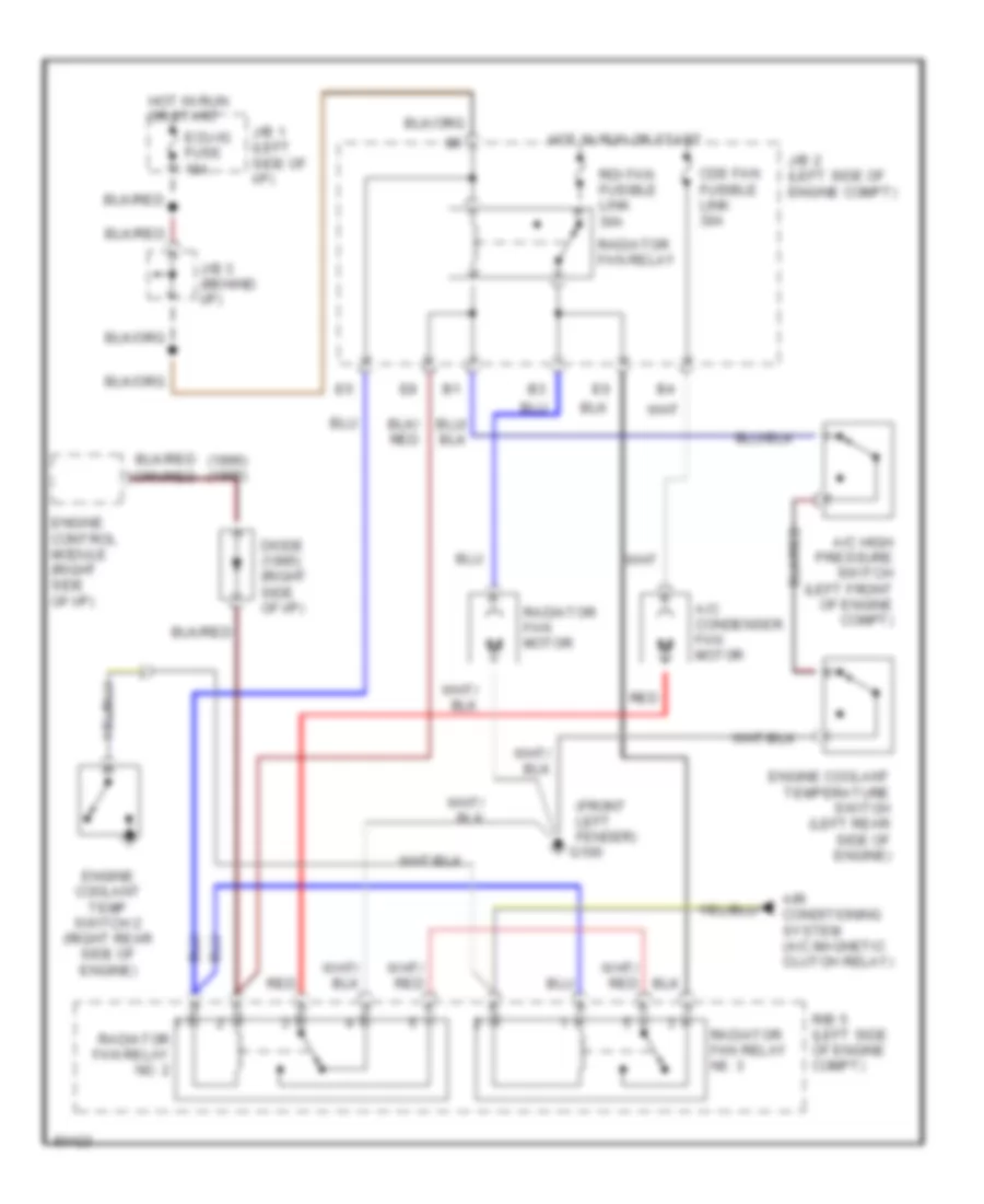
2.2L, Cooling Fan Wiring Diagram for Toyota Camry XLE 1995
List of elements for 2.2L, Cooling Fan Wiring Diagram for Toyota Camry XLE 1995:
- (front left fender)
- A/c condenser fan motor
- A/c high pressure switch (left front of engine compt)
- Air conditioning system (a/c magnetic clutch relay)
- Cds fan fusible link 30a
- Ecu-ig fuse 15a
- G100
- Hot in run or start
- J/b 1 (left side of i/p)
- J/b 2 (left side of engine compt)
- J/b 3 (behind i/p)
- R/b 5 (left side of engine compt)
- Radiator fan motor
- Radiator fan relay
- Radiator fan relay n0. 3
- Radiator fan relay no. 2
- Rdi fan fusible link 30a
- Red
- Water temperature switch (right radiator switch)
3.0L
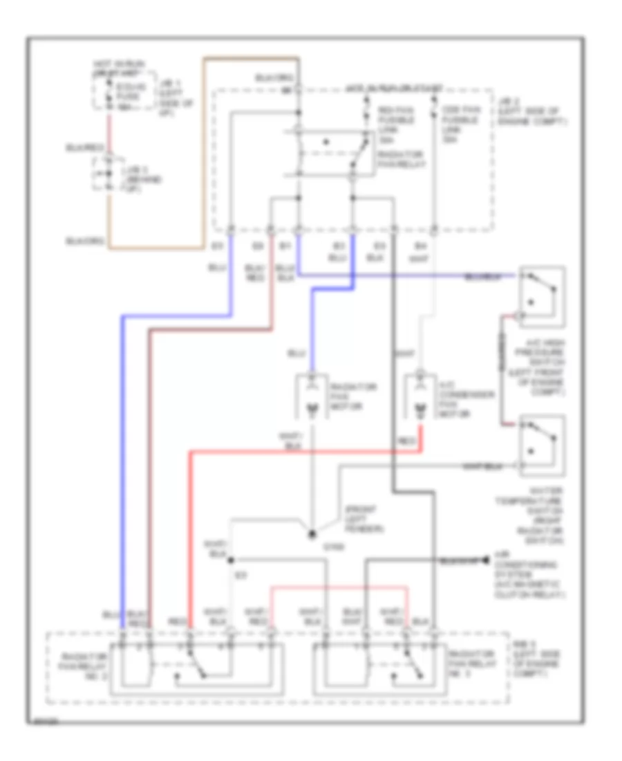
3.0L, Cooling Fan Wiring Diagram for Toyota Camry XLE 1995
List of elements for 3.0L, Cooling Fan Wiring Diagram for Toyota Camry XLE 1995:
- (front left fender) g100
- A/c condenser fan motor
- A/c high pressure switch (left front of engine compt)
- Air conditioning system (a/c magnetic clutch relay)
- Cds fan fusible link 30a
- Diode (1995) (right side of i/p)
- Ecu-ig fuse 15a
- Engine control module (right side of i/p)
- Engine coolant temp switch 2 (right rear side of engine)
- Engine coolant temperature switch (left rear side of engine)
- Hot in run or start
- J/b 1 (left side of i/p)
- J/b 2 (left side of engine compt)
- J/b 3 (behind i/p)
- R/b 5 (left side of engine compt)
- Radiator fan motor
- Radiator fan relay
- Radiator fan relay n0. 3
- Radiator fan relay no. 2
- Rdi fan fusible link 30a
- Red
CRUISE CONTROL
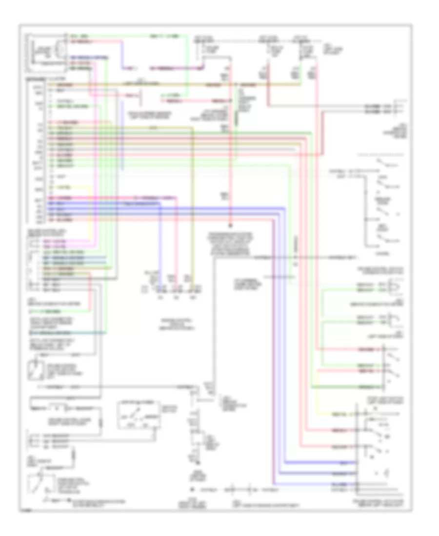
Cruise Control Wiring Diagram for Toyota Camry XLE 1995
List of elements for Cruise Control Wiring Diagram for Toyota Camry XLE 1995:
- (a/t)
- (i/p harness, under center dash cover)
- (m/t)
- 2.2l
- 3.0l
- A/d
- A12
- A14
- A15
- Acc
- B10
- B12
- B13
- B14
- B15
- B16
- B17
- B18
- B19
- Batt
- C11
- C16
- C18
- C19
- Cancel
- Ccs
- Cms
- Cruise control actuator (behind left headlight)
- Cruise control clutch switch (left side of dash) (m/t)
- Cruise control diode (right side of dash)
- Cruise control ecu (behind glove box)
- Cruise control ind
- Cruise control switch (combination switch)
- D16
- D22
- Data link connector 1 (right rear of engine compartment)
- Data link connector 2 (below dash, left of steering column)
- E10
- E20
- Ect
- Ecu-ig fuse 15a
- Engine control module (behind glove box)
- G100 (front of left front fender)
- G206 (center of dash)
- Gauge fuse
- Gnd
- Hot at all times
- Hot in on and start
- I13
- I18 (i/p harness, behind lower right side of dash)
- Idl
- Ignition switch
- Instrument cluster
- J/b 1 (left side of dash)
- J/b 2 (left side of engine compartment)
- J/b 3 (behind combination meter)
- J/c 1 (left side of dash)
- Main
- N&c
- Od1
- Off
- Park/neutral position switch (on top of transaxle)
- Pnk
- Resume/ accel
- Set/ coast
- Solid state
- Spd
- Start
- Starting/charging system (starter relay)
- Stop fuse 15a
- Stop light switch (left side of dash)
- Stp+
- Stp-
- Transmissions system (park/neutral position switch (a/t), back-up light switch (m/t)), starting/charging system (generator)
- Vehicle speed sensor (left side of engine)
- Vr1
- Vr2
- Vr3
- Vss output
DEFOGGERS
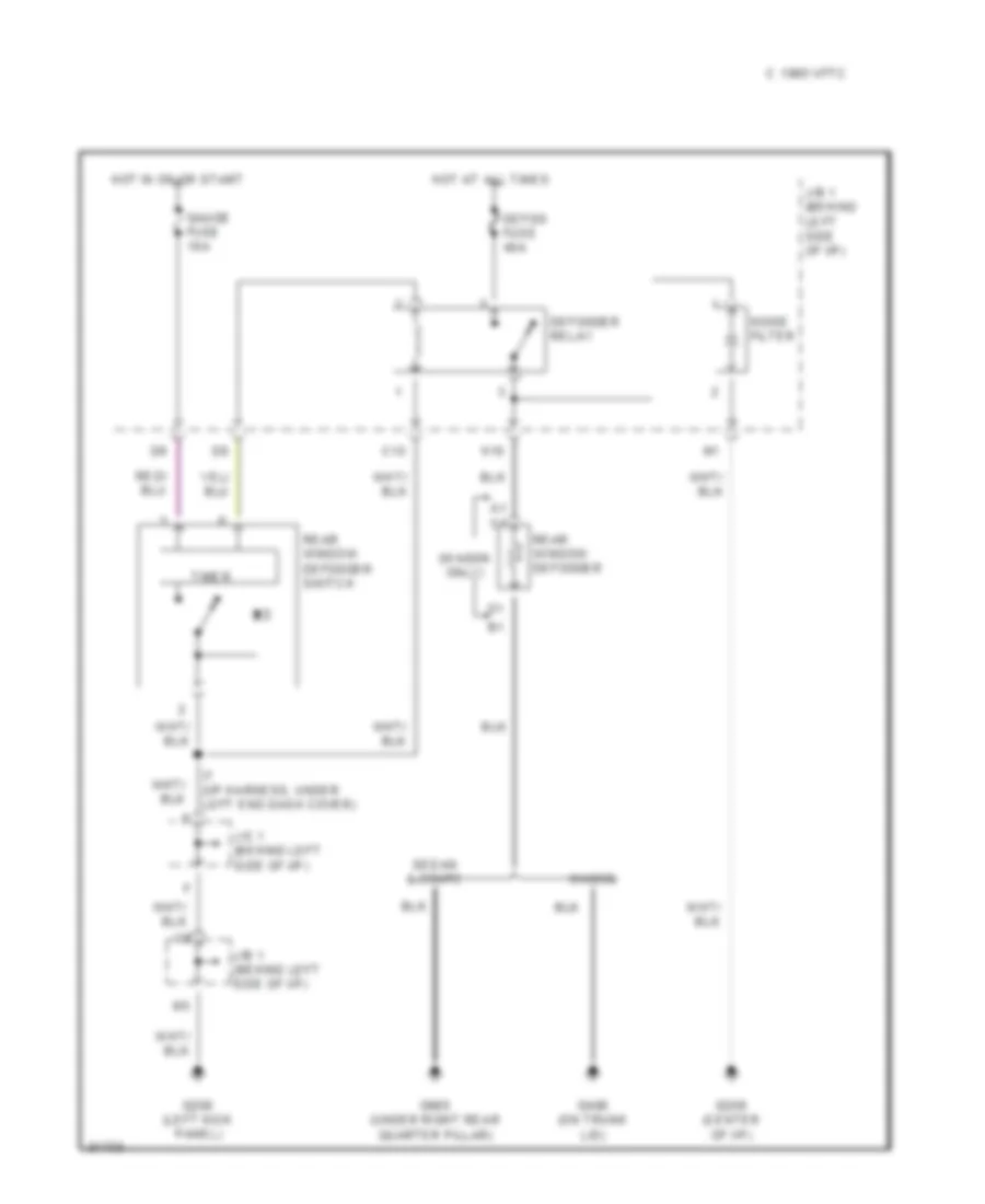
Defogger Wiring Diagram for Toyota Camry XLE 1995
List of elements for Defogger Wiring Diagram for Toyota Camry XLE 1995:
- (wagon only)
- C 1995 vftc
- C10
- Defog fuse 40a
- Defogger relay
- G200 (left kick panel)
- G206 (center of i/p)
- G406 (on trunk lid)
- G905 (under right rear quarter pillar)
- Gauge fuse 10a
- H10
- Hot at all times
- Hot in on or start
- I7 (i/p harness, under left end dash cover)
- J/b 1 (behind left side of i/p)
- J/c 1 (behind left side of i/p)
- Noise filter
- Rear window defogger
- Rear window defogger switch
- Sedan & coupe
- Timer
- Wagon
ENGINE PERFORMANCE
2.2L
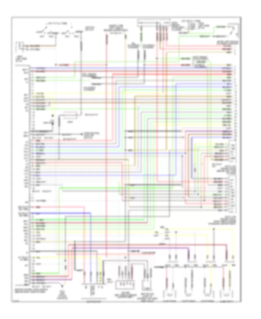
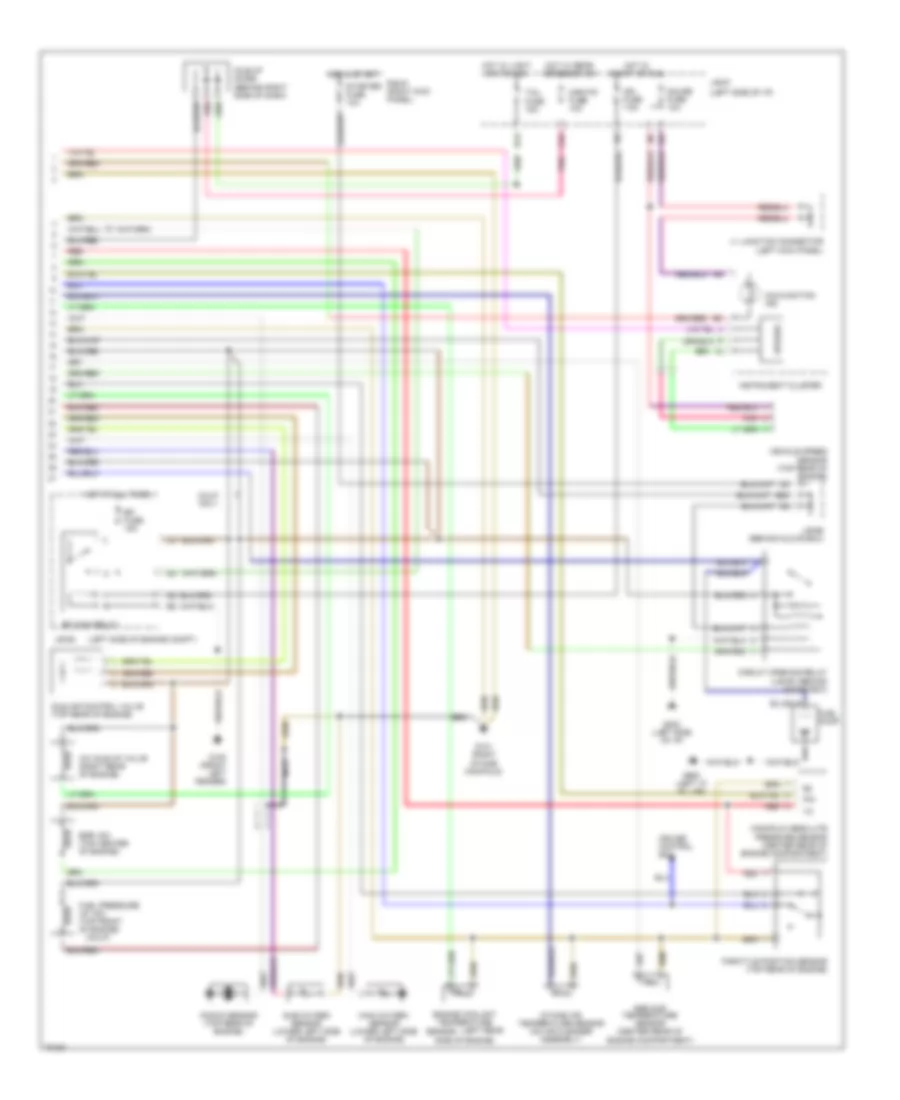
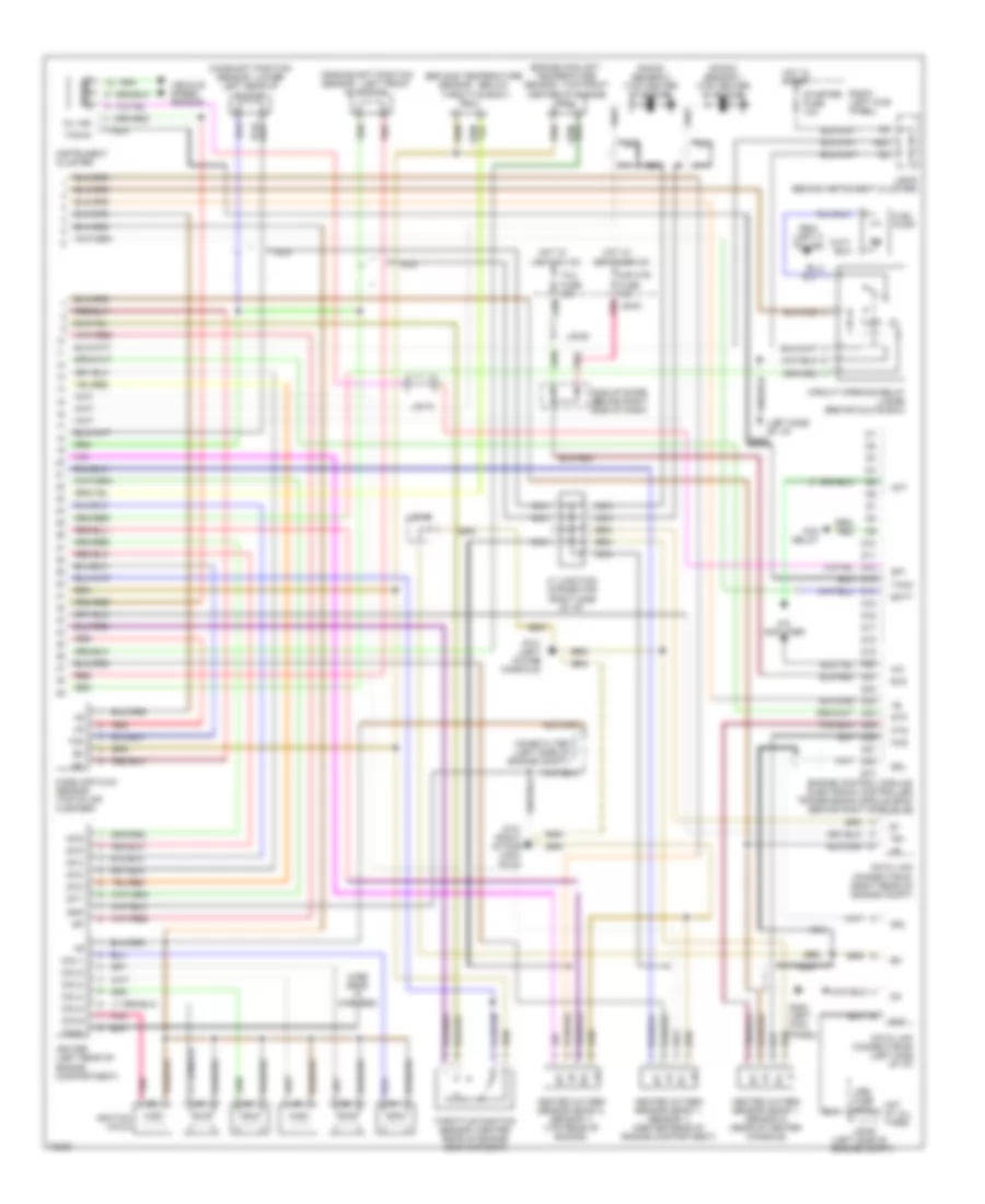
2.2L, Engine Performance Wiring Diagrams, A/T & California M/T (1 of 2) for Toyota Camry XLE 1995
List of elements for 2.2L, Engine Performance Wiring Diagrams, A/T & California M/T (1 of 2) for Toyota Camry XLE 1995:
- #10
- #20
- #30
- #40
- (a/t)
- (left side of i/p)
- (m/t)
- (stop light switch (on pedal support)
- +b1
- A/c amplifier
- Aca
- Acc
- Act
- B/k
- Batt
- Calif
- California & canada
- Canada & california
- Coil-
- D10
- D18
- D19
- D22
- Data link connector #1 (right rear corner of engine compartment)
- Data link connector #2 (behind left side of dash)
- Distributor
- E01
- E02
- E10
- E11
- E12
- E14
- Egr
- Els
- Eng
- Engine control module (ecm) (behind right side of dash)
- Ex calif m/t
- Ex. california & canada
- Exc canada & california
- Exc. canada & california
- Fed
- Fpu
- G1 (calif) g+ (fed)
- G131 (left intake manifold)
- G2 (calif) ne- (fed)
- Hot at all times
- Idl
- Ig-
- Igf
- Igniter (left side of engine compartment)
- Ignition coil (part of distributor assy) (exc. calif)
- Ignition switch
- Igt
- Injector #1
- Injector #2
- Injector #3
- Injector #4
- Iscc
- Isco
- Iscv
- J/b #1
- J/b #1 (left side of i/p)
- J/b #3 (behind instrument cluster)
- Knk
- Lock
- Nca
- Ne (calif) ne+ (fed)
- Noise filter (left side of engine compartment)
- Nsw
- Ox1
- Ox2
- Park/neutral position switch
- Pim
- Red
- Run
- Sp1
- Sta
- Start
- Stop fuse 15a
- Tachometer
- Te1
- Te2
- Tha
- Thg
- Thw
- Vf1
- Vta
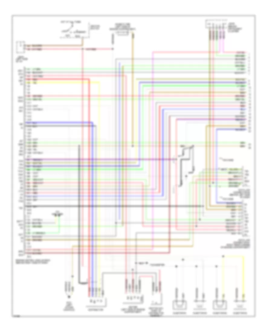
2.2L, Engine Performance Wiring Diagrams, A/T & California M/T (2 of 2) for Toyota Camry XLE 1995
List of elements for 2.2L, Engine Performance Wiring Diagrams, A/T & California M/T (2 of 2) for Toyota Camry XLE 1995:
- (calif)
- (left rear
- (left side of engine compt)
- (left side of i/p)
- A/c idle-up valve (right rear of engine)
- A10
- B20
- Calif only
- Circuit opening relay (j/b #3) (behind glove box)
- Cruise control ecu
- D14
- Efi fuse 15a
- Efi main relay
- Egr gas temperature sensor (center rear of engine compartment)
- Egr vsv (top center of engine)
- Engine coolant temperature
- Fuel pressure up vsv (top front of engine)
- Fuel pump
- G100 (front left fender)
- G131 (right intake manifold)
- G202 (left side of i/p)
- G900 (left "a" pillar)
- Gauge fuse 10a
- Hot at all times
- Hot in start
- Hot in start or run
- Hot w/ light switch on
- Hot w/ rear defogger on
- Idle air control valve (top rear of engine)
- Idle-up diode (behind right side of dash)
- Ign fuse 7.5a
- Instrument cluster
- Intake air temperature sensor (on air cleaner assembly)
- J/b #1
- J/b #2
- J/b #6 (behind glove box)
- J1 junction connector (left kick panel)
- Knock sensor (top rear of engine)
- Main oxygen sensor (lower left side of engine)
- Malfunction ind
- Manifold absolute pressure sensor (center rear of engine compartment)
- Mir-htr fuse 10a
- Nca
- Pim
- Pnk
- R/b #1 (right kick panel)
- Red
- Sensor
- Side of engine)
- Speedo
- Starter fuse 10a
- Sub oxygen sensor (lower left side of engine)
- Tail fuse 15a
- Throttle position sensor (top rear of engine)
- Vehicle speed sensor (top rear of engine)
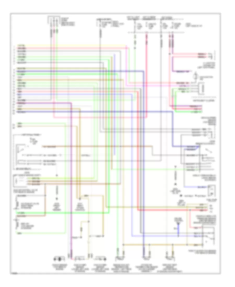
2.2L, Engine Performance Wiring Diagrams, M/T Except California (1 of 2) for Toyota Camry XLE 1995
List of elements for 2.2L, Engine Performance Wiring Diagrams, M/T Except California (1 of 2) for Toyota Camry XLE 1995:
- #10
- #20
- (left side of i/p)
- A/c amplifier
- A10
- A11
- A12
- A13
- A14
- A15
- A16
- A17
- A18
- A19
- A20
- A21
- A22
- A23
- A24
- A25
- A26
- Aca
- Acc
- Act
- B10
- B11
- B12
- B13
- B14
- B15
- B16
- Batt
- C10
- C11
- C12
- Coil-
- Data link connector #1 (right rear corner of engine compartment)
- Data link connector #2 (behind left side of dash)
- Distributor
- E01
- E02
- E11
- E12
- E14
- Egr
- Els
- Eng
- Engine control module (ecm) (behind right side of dash)
- G131 (left intake manifold)
- Hot at all times
- Idl
- Ig-
- Igf
- Igniter (left side of engine compartment)
- Ignition coil (part of distributor assembly)
- Ignition switch
- Igt
- Injector #1
- Injector #2
- Injector #3
- Injector #4
- Iscc
- Isco
- Iscv
- J/b #1
- J/b #3 (behind instrument cluster)
- Knk
- Lock
- Nca
- Ne+
- Ne-
- Noise filter (left side of engine compartment)
- Ox1
- Ox2
- Pim
- Red
- Run
- Spd
- Sta
- Start
- Tachometer
- Te1
- Te2
- Tha
- Thg
- Thw
- Tmc made
- Tmm made
- Vf1
- Vta
2.2L, Engine Performance Wiring Diagrams, M/T Except California (2 of 2) for Toyota Camry XLE 1995
List of elements for 2.2L, Engine Performance Wiring Diagrams, M/T Except California (2 of 2) for Toyota Camry XLE 1995:
- (left rear
- (left side of engine compt)
- A/c idle-up valve (right rear of engine)
- A10
- B20
- Circuit opening relay (j/b #3) (behind glove box)
- Cruise control
- D14
- Ecu
- Efi fuse 15a
- Efi main relay
- Egr gas temp sensor (center rear of engine compartment)
- Egr vsv (top center of engine)
- Engine coolant temperature
- Fuel pump
- G100 (front left fender)
- G131 (right intake manifold)
- G202 (left side of i/p)
- G900 (left "a" pillar)
- Gauge fuse 10a
- Hot at all times
- Hot in run or start
- Hot in start
- Hot w/ light switch on
- Hot w/ rear defogger on
- Idle air control valve (top rear of engine)
- Idle-up diode (behind right side of dash)
- Ign fuse 7.5a
- Instrument cluster
- Intake air temperature sensor (on air cleaner assembly)
- J/b #1 (left side of i/p)
- J/b #2
- J/b #6 (behind glove box)
- J1 junction connector (left kick panel)
- Knock sensor (top rear of engine)
- Main oxygen sensor (lower left side of engine)
- Malfunction ind
- Manifold absolute pressure sensor (center rear of engine compartment)
- Mir-htr fuse 10a
- Nca
- Pim
- Pnk
- R/b #1 (right kick panel)
- Red
- Sensor
- Side of engine)
- Speedo
- Starter fuse 10a
- Sub oxygen sensor (lower left side of engine)
- Tail fuse 15a
- Throttle position sensor (top rear of engine)
- Vehicle speed sensor (top rear of engine)
3.0L
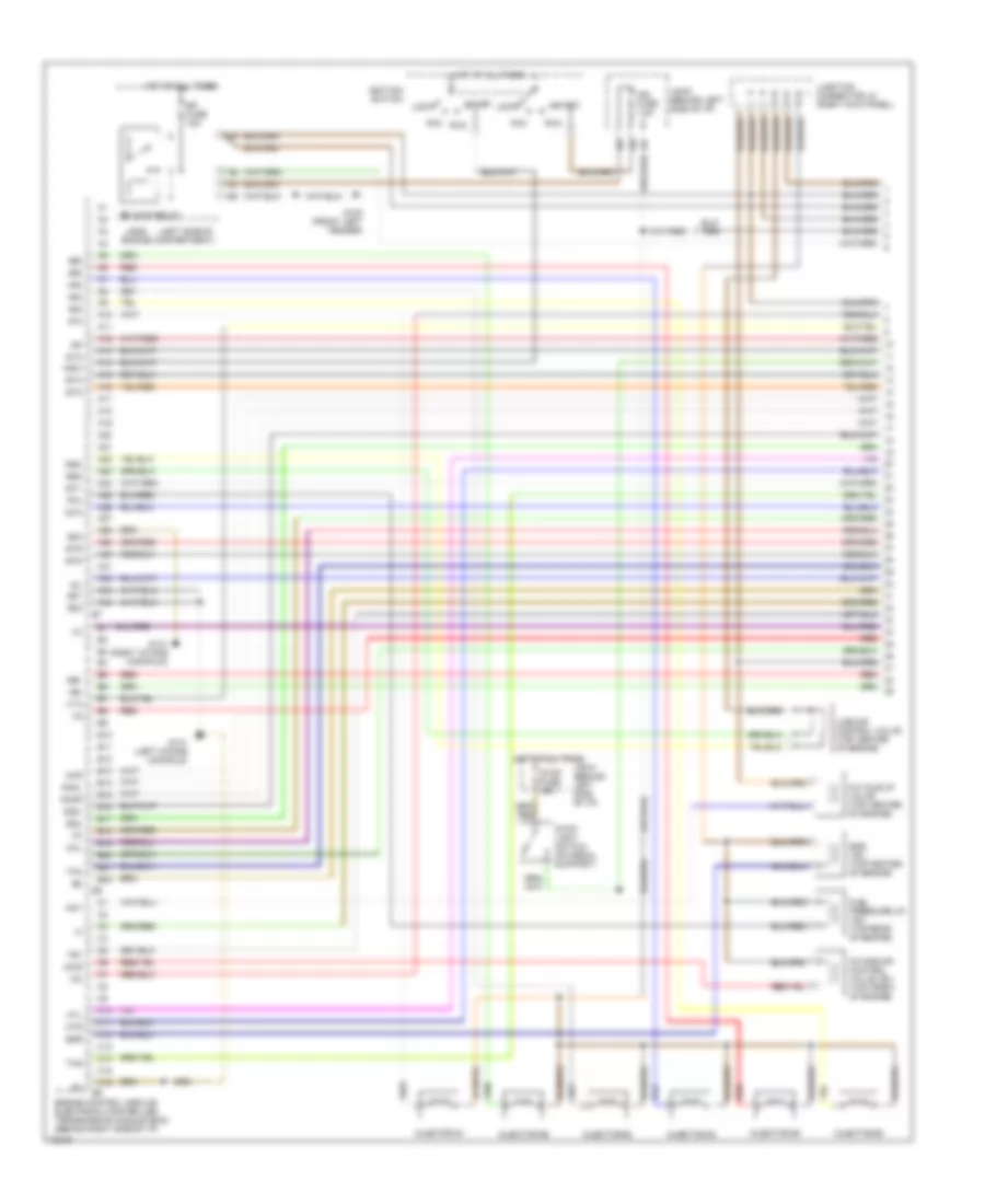
3.0L, Engine Performance Wiring Diagrams (1 of 2) for Toyota Camry XLE 1995
List of elements for 3.0L, Engine Performance Wiring Diagrams (1 of 2) for Toyota Camry XLE 1995:
- #10
- #20
- #30
- #40
- #50
- #60
- (left side of
- A/c idle-up valve (top center of engine)
- A10
- A11
- A12
- A13
- A14
- A15
- A16
- A17
- A18
- A19
- A2 a3
- A20
- A21
- A22
- A23
- A24
- A25
- A26
- A27
- A28
- A29
- A30
- A31
- A32
- A33
- A34
- Acc
- Acis
- Acv
- B10
- B11
- B12
- B13
- B14
- B15
- B16
- B17
- B18
- B19
- B20
- B21
- B22
- C10
- C11
- C12
- C13
- C14
- C15
- C16
- E01
- E02
- E03
- Efi fuse 15a
- Efi main relay
- Egr
- Egr vsv (top center of engine)
- Engine compartment)
- Engine control module/ electronic controlled transmission module (ecm) (behind right side of i/p)
- Fpu
- Fuel pressure up vsv (top rear of engine)
- G100 (front left fender)
- G131 (left intake manifold)
- G131 (right intake manifold)
- G22+
- G22-
- Hot at all times
- Htl
- Htr
- Idl
- Igf
- Ign fuse 7.5a
- Ignition switch
- Igt1
- Igt2
- Igt3
- Igt4
- Igt5
- Igt6
- Ilde air control valve (top center of engine)
- Injector #1
- Injector #2
- Injector #3
- Injector #4
- Injector #5
- Injector #6
- Intake air control valve vsv (top front of engine)
- J/b #1 (behind left side of i/p)
- J/b #1 (behind left side of i/p)
- J/b #2
- Junction connector j8 (right kick panel)
- Knkl
- Knkr
- Lock
- Ne+
- Ne-
- Nsw
- Oxl
- Oxr
- Red
- Rsc
- Rso
- Run
- Sta
- Start
- Stop fuse 15a
- Stop light switch (on pedal support)
- Te1
- Tha
- Thg
- Vg-
- Vta
3.0L, Engine Performance Wiring Diagrams (2 of 2) for Toyota Camry XLE 1995
List of elements for 3.0L, Engine Performance Wiring Diagrams (2 of 2) for Toyota Camry XLE 1995:
- (below
- (center
- (left front
- (left side of engine compt)
- (left side of i/p)
- (lower
- (right side of i/p)
- (top front
- +b +b
- A/c
- A/c amplifier
- Act
- B20
- Bat
- Batt
- Camshaft position
- Center of engine)
- Circuit opening relay (j/b #6) (behind glove box)
- Coil1
- Coil2
- Coil3
- Coil4
- Coil5
- Coil6
- Crankshaft position
- D10
- D11
- D12
- D13
- D14
- D15
- D16
- D17
- D18
- D19
- D20
- D21
- D22
- D23
- D24
- D25
- D26
- D27
- D28
- Data link connector #1 (right rear of engine compt)
- Data link connector #3 (left side of i/p)
- Defogger on
- E e
- E10
- Egr gas temperature
- Els
- Engine control module/ electronic controlled transmission module (ecm) (behind right side of i/p)
- Engine coolant temperature
- Fan relay
- Fuel pump
- G131 (left intake manifold)
- G131 (right intake mani- fold)
- G200 (left kick panel)
- G202
- G904 (left c pillar)
- Gnd
- Heated oxygen sensor (bank 1, sensor 1) (center rear of engine compartment)
- Heated oxygen sensor (bank 1, sensor 2) (rear of center console)
- Heated oxygen sensor (bank 2, sensor 1) (top rear of engine)
- Hot at all times
- Hot in start
- Hot w/
- Ht ht
- Hts
- Idle-up diode (behind right side of dash)
- Igf
- Igniter (left rear of engine compartment)
- Ignition coils
- Igt1
- Igt2
- Igt3
- Igt4
- Igt5
- Igt6
- Instrument cluster
- J/b #1
- J/b #2
- J/b #3
- J/b #3 (behind instrument cluster)
- J7 junction connector
- Knock sensor 1 (top center of engine)
- Knock sensor 2 (top center of engine)
- Left rear of engine)
- Light sw on
- Mass air flow sensor (top of air cleaner)
- Mil ind
- Mir htr fuse 10a
- Nca
- Noise filter (left side of engine compt)
- Obd fuse 7.5a
- Of engine)
- Ox ox
- Oxs
- Pnk
- R/b #1 (left kick panel)
- Rear of engine compartment)
- Red
- Sdl
- Sensor
- Sp1
- Speed
- Starter fuse 10a
- Stp
- Tach
- Tacho
- Taco
- Tail fuse 15a
- Te1
- Tha
- Throttle body)
- Throttle position
- Vehicle speed sensor
- Vg-
- Wire ends in harness
EXTERIOR LIGHTS
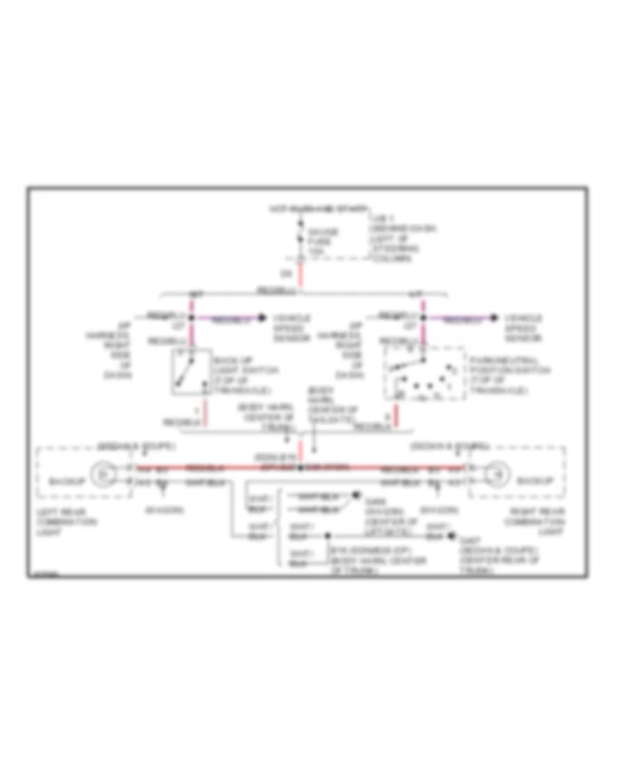
Back-up Lamps Wiring Diagram for Toyota Camry XLE 1995
List of elements for Back-up Lamps Wiring Diagram for Toyota Camry XLE 1995:
- (body harn, center of tailgate)
- (body harn, center of trunk)
- (i/p harness, right side of dash)
- (sdn) b16 (cp) b29
- (sedan & coupe)
- (wagon)
- A/t
- B16 (sdn)/b29 (cp) (body harn, center of trunk)
- B38 (wgn)
- Back-up light switch (top of transaxle)
- Backup
- G406 (wagon) (center of liftgate)
- G407 (sedan & coupe) (center rear of trunk)
- Gauge fuse 10a
- Hot in on and start
- I27
- J/b 1 (behind dash, left of steering column)
- Left rear combination light
- M/t
- Park/neutral position switch (top of transaxle)
- Right rear combination light
- Vehicle speed sensor
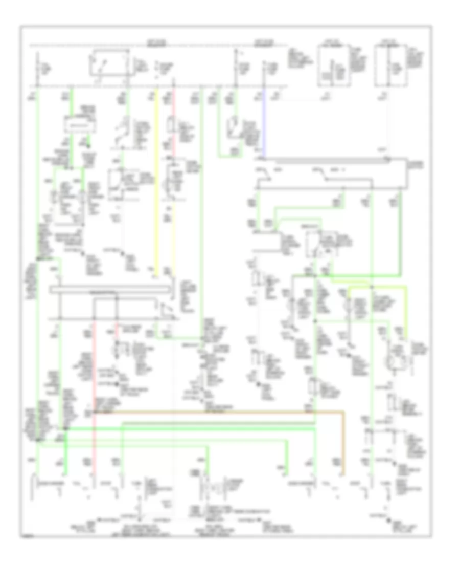
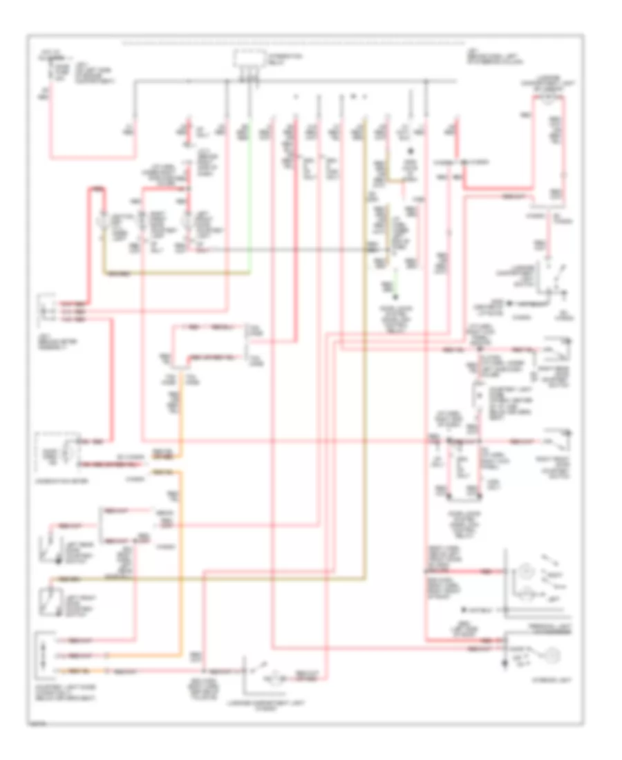
Exterior Lamps Wiring Diagram, Sedan & Coupe for Toyota Camry XLE 1995
List of elements for Exterior Lamps Wiring Diagram, Sedan & Coupe for Toyota Camry XLE 1995:
- (1995) (1996)
- (1996) (1995)
- (behind meter assembly) j/b 3
- (body harn, behind left rear comb- ination light)
- (body harn, behind left rear comb- ination light) (cp) b28
- (body harn, behind left rear comb- ination light) b28 (cp)
- (body harn, behind left rear combination light) b28 (cp)
- (body harn, below left "d" pillar) b10 (sdn)/ b26 (cp)
- (body harn, left corn- er of trunk) (sdn) b13
- (body harn, left corner of (body trunk) harn, behind left rear comb- ination light) (cp) b28
- (body harn, left corner of trunk) b13 (sdn) b28 (cp)
- (cp) b25
- (engine harn, above grille opening) e4
- 120a
- Alt fuse 100a (2.2l) (3.0l)
- B10 (sdn)
- B12 (sdn) (body harn, above left rear tail- light)
- B13 (sdn)
- B14 (sdn)/b28 (cp) (body harn, behind left rear combination light)
- B15 (sdn) (body harn, center rear of trunk)
- B16 (sdn)
- C11
- C18
- Comb- ination meter
- Comb- ination switch
- D14
- E4 (engine harn, above grille opening)
- Fuse box (on left side of engine compt)
- G100 (front of left front fender)
- G101 (front of right front fender)
- G200 (left kick panel)
- G206 (center of dash)
- G407 (center rear of cargo area)
- G407 (center rear of trunk)
- G999 (below left "d" pillar)
- Gauge fuse 10a
- H16
- H17
- Haz fuse 10a
- Hazard switch
- Head
- High mounted stop light (w/ rear spoiler only)
- High mounted stop light (w/o rear spoiler only)
- Hot at all times
- Hot in on or start
- I11 (i/p harn, behind center of dash)
- I7 (i/p harn, under left end dash cover)
- Idle-up diode (1996 only)
- Integ- ration relay (on rear of j/b 1)
- J/b 1 (behind dash, left of steering column)
- J/b 2 (on left side of engine compt)
- J/b 3 (behind meter assembly)
- J/c 1 (below left side of dash)
- Left front side marker & park- ing light
- Left front turn signal light
- Left rear combination light
- License plate light
- Light ctrl switch
- Light failure sensor (on left side of trunk)
- Off
- Rear light warn- ing ind
- Red
- Right front side marker & park- ing light
- Right front turn signal light
- Right rear combination light
- Side marker
- Solid state
- Stop
- Stop fuse 15a
- Stop light switch (above brake pedal)
- Tail
- Tail fuse 15a
- Tail- light relay
- Turn
- Turn fuse 7.5a
- Turn signal flasher (on r/b 1)
- Turn signal ind
- Turn signal switch
- Under left end dash cover)
- W/ rear spoiler
- W/o rear spoiler
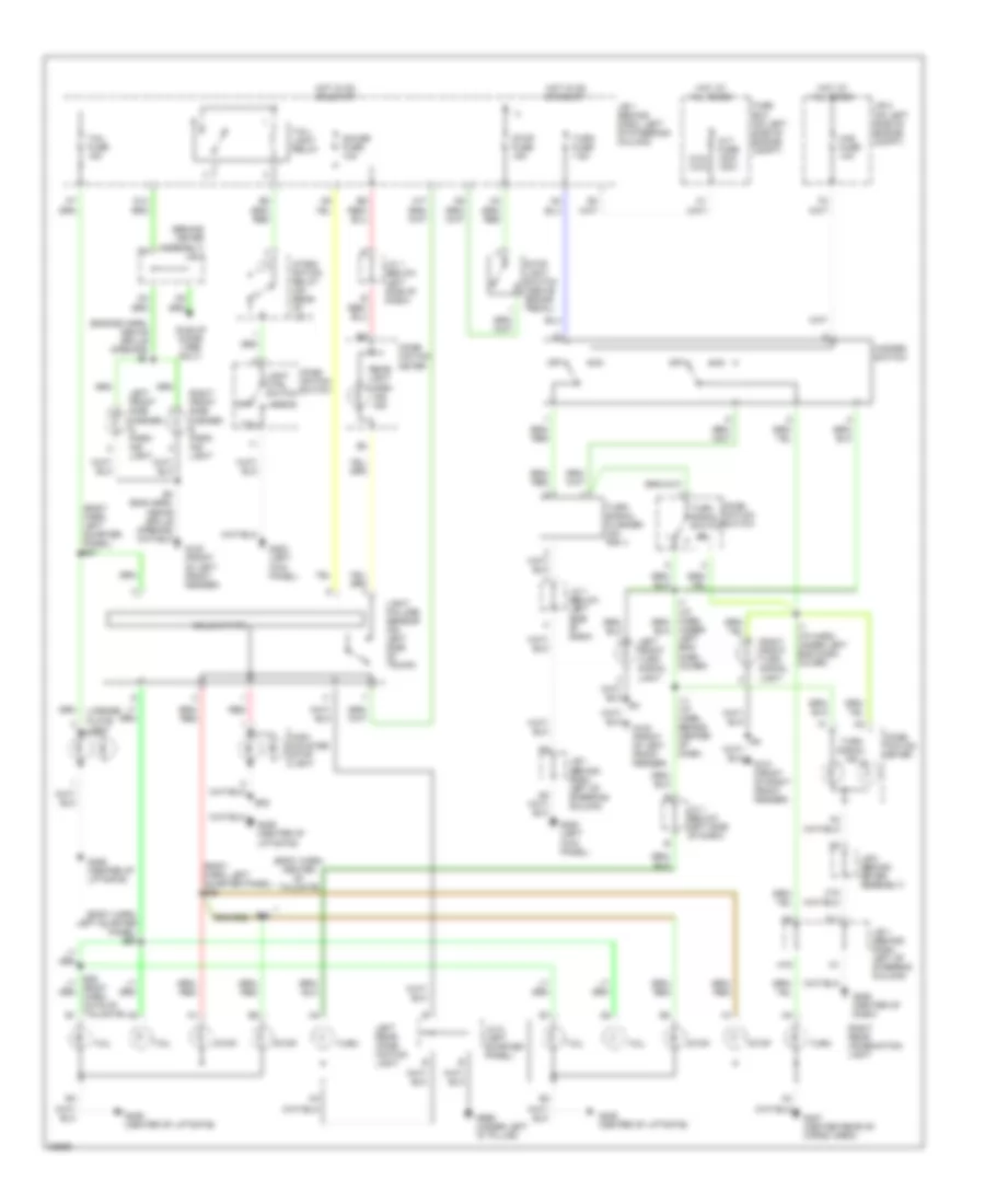
Exterior Lamps Wiring Diagram, Wagon for Toyota Camry XLE 1995
List of elements for Exterior Lamps Wiring Diagram, Wagon for Toyota Camry XLE 1995:
- (behind meter assembly) j/b 3
- (body harn, center of tailgate)
- (body harn, left quarter panel) b36
- (body harn, left quarter panel) b37
- (engine harn, above grille opening) e4
- 120a
- Alt fuse 100a (2.2l) (3.0l)
- B38
- C11
- C18
- Comb- ination meter
- Comb- ination switch
- D14
- Fuse box (on left side of engine compt)
- G100 (front of left front fender)
- G101 (front of right front fender)
- G200 (left kick panel)
- G206 (center of dash)
- G406 (center of liftgate)
- G407 (center rear of cargo area)
- G999 (under left "d" pillar)
- Gauge fuse 10a
- H16
- H17
- Haz fuse 10a
- Hazard switch
- Head
- High mounted stop light
- Hot at all times
- Hot in on or start
- I11 (i/p harn, behind center of dash)
- I7 (i/p harn, under left end dash cover)
- Idle-up diode (1996 only)
- Integ- ration relay (on rear of j/b 1)
- J/b 1 (behind dash, left of steering column)
- J/b 2 (on left side of engine compt)
- J/b 3 (behind meter assembly)
- J/c 1 (below left side of dash)
- J/c 5 (left quarter panel)
- Left front side marker & park- ing light
- Left front turn signal light
- Left rear comb- ination light
- License plate light
- Light ctrl switch
- Light failure sensor (on left side of trunk)
- Off
- Rear light warn- ing ind
- Red
- Right front side marker & park- ing light
- Right front turn signal light
- Right rear combination light
- Solid state
- Stop
- Stop fuse 15a
- Stop light switch (above brake pedal)
- Tail
- Tail fuse 15a
- Tail- light relay
- Turn
- Turn fuse 7.5a
- Turn signal flasher (on r/b 1)
- Turn signal ind
- Turn signal switch
- Under left end dash cover)
GROUND DISTRIBUTION
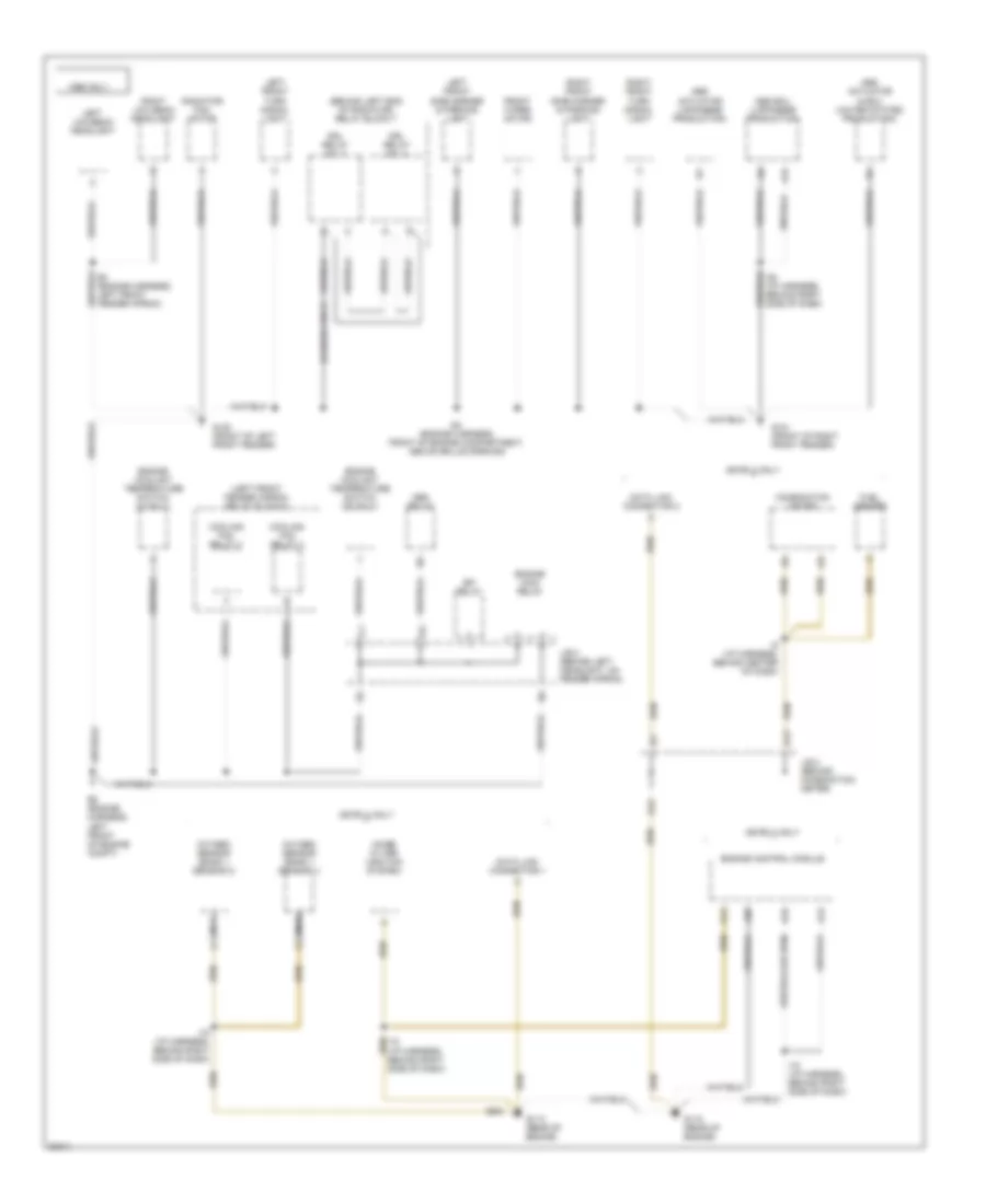
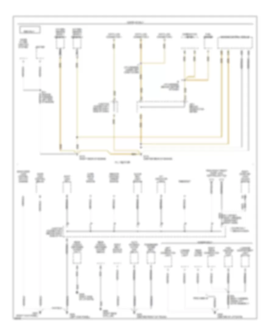
Ground Distribution Wiring Diagram (1 of 6) for Toyota Camry XLE 1995
List of elements for Ground Distribution Wiring Diagram (1 of 6) for Toyota Camry XLE 1995:
- (behind left end of radiator) relay block 7
- (canada only)
- (left front fender apron) relay block 5
- 1996 only
- 5s-fe i4 only
- A13
- A14
- A15
- A26
- Abs actuator & ecu (united states production)
- Abs actuator (japanese production)
- Abs ecu (japanese production)
- Abs relay
- B16
- Combination meter
- Cooling fan relay 2
- Cooling fan relay 3
- D12
- D13
- Data link connector 1
- Data link connector 2
- Drl relay no. 3
- Drl relay no. 4
- E3 (engine harness, left front fender apron)
- E4 (engine harness, front of engine compartment, above grille opening)
- E5 (engine harness, left front of engine compt)
- Efi relay
- Engine control module
- Engine coolant temperature switch (i4 only)
- Engine coolant temperature switch (v6 only)
- Engine main relay
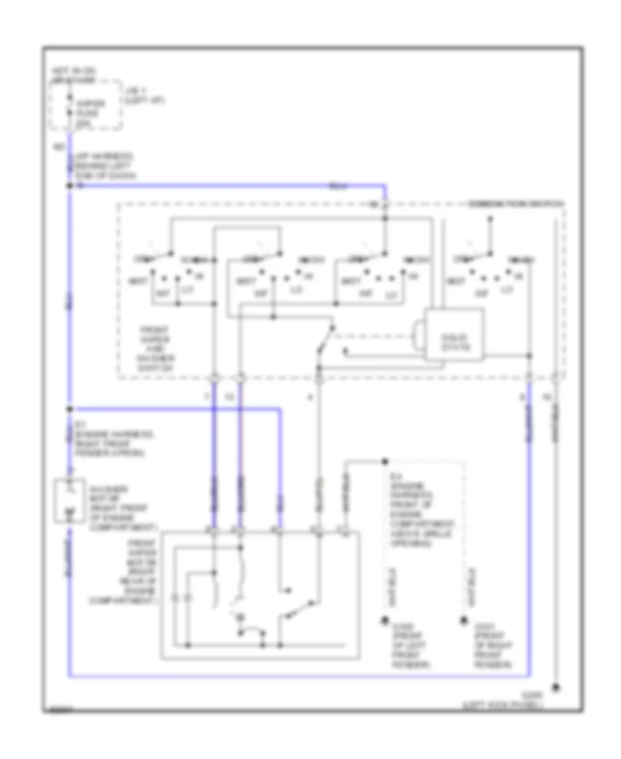
- Front wiper motor
- Fuel sender
- G100 (front of left front fender)
- G101 (front of right front fender)
- G115 (rear of engine)
- I18 (i/p harness, behind right side of dash)
- I25 (i/p harness, behind right side of dash)
- I9 (i/p harness, behind center of dash)
- J/b 2 (behind left headlight, on fender apron)
- J/b 3 (behind combination meter)
- Left front side marker & parking light
- Left front turn signal light
- Left low beam headlight
- Nca
- Noise filter (ignition system)
- Oxygen sensor (bank 1 sensor 1)
- Oxygen sensor (bank 1 sensor 2)
- Radiator fan motor
- Right front side marker & parking light
- Right front turn signal light
- Right low beam headlight
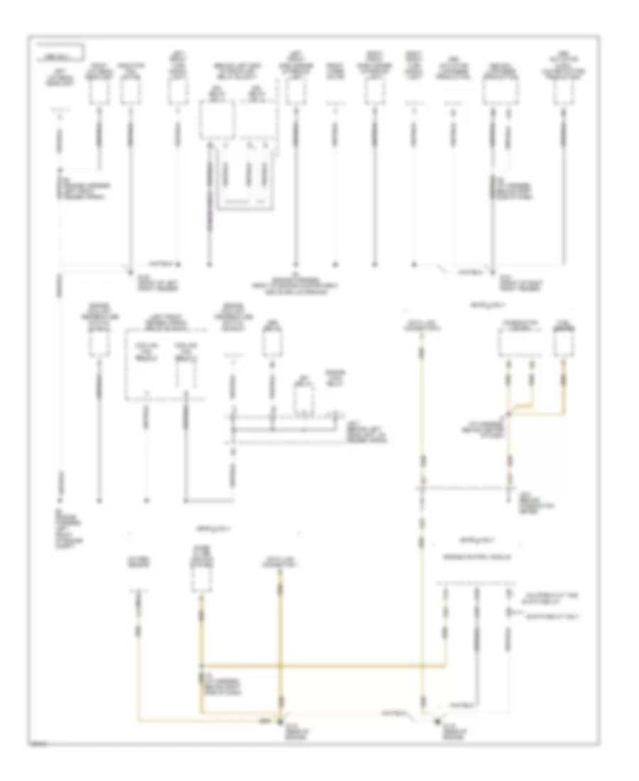
Ground Distribution Wiring Diagram (2 of 6) for Toyota Camry XLE 1995
List of elements for Ground Distribution Wiring Diagram (2 of 6) for Toyota Camry XLE 1995:
- 50 states a/t
- (behind left end of radiator) relay block 7
- (canada only)
- (left front fender apron) relay block 5
- 1995 only
- 49 states m/t only
- 5s-fe i4 only
- A13
- A15
- A24
- A26
- Abs actuator & ecu (united states production)
- Abs actuator (japanese production)
- Abs ecu (japanese production)
- Abs relay
- C13
- C14
- C26
- California m/t and
- Combination meter
- Cooling fan relay 2
- Cooling fan relay 3
- D12
- D13
- Data link connector 1
- Data link connector 2
- Drl relay no. 3
- Drl relay no. 4
- E3 (engine harness, left front fender apron)
- E4 (engine harness, front of engine compartment, above grille opening)
- E5 (engine harness, left front of engine compt)
- Efi relay
- Engine control module
- Engine coolant temperature switch (i4 only)
- Engine coolant temperature switch (v6 only)
- Engine main relay
- Front wiper motor
- Fuel sender
- G100 (front of left front fender)
- G101 (front of right front fender)
- G115 (rear of engine)
- I18 (i/p harness, behind right side of dash)
- I25 (i/p harness, behind right side of dash)
- I9 (i/p harness, behind center of dash)
- J/b 2 (behind left headlight, on fender apron)
- J/b 3 (behind combination meter)
- Left front side marker & parking light
- Left front turn signal light
- Left low beam headlight
- Nca
- Noise filter (ignition system)
- Oxygen sensor
- Radiator fan motor
- Right front side marker & parking light
- Right front turn signal light
- Right low beam headlight
Ground Distribution Wiring Diagram (3 of 6) for Toyota Camry XLE 1995
List of elements for Ground Distribution Wiring Diagram (3 of 6) for Toyota Camry XLE 1995:
- (left kick panel) relay block 1
- (right kick panel) relay block 4
- A/c amplifier
- Air vent mode control servo motor
- B4, (b21 or b31) (body harness, above left front door)
- B4, (b30 or b20) (body harness, above left front door)
- B5, (b21 or b32) (body harness, windshield header)
- Blower resistor
- Blower switch
- Brake fluid level warning switch
- C10
- C11
- Center airbag sensor assembly
- Cigarette lighter
- Clock
- Data link connector 3
- Defogger relay
- Dimmer switch
- From starter a relay (j/b 2)
- G200 (left kick panel)
- G203 (right kick panel)
- G206 (center of dash)
- G902 (left side of roof)
- Heater control switch (push type)
- Heater relay
- High beam indicator (canada only)
- I12 (i/p harness, behind center of dash)
- I13 (i/p harness, under center dash cover)
- I3 (i/p harness, under center dash cover)
- I5 (i/p harness, behind left end of dash)
- I7 (i/p harness, under left side of dash)
- I7 (or i4) (i/p harness, under left side of dash)
- Integration relay
- J/b 1 (behind left side of i/p)
- Junction connector 1 (behind combination meter)
- Key interlock solenoid
- Left vanity light
- Light control switch
- Mode control switch (lever type)
- Moon roof control relay
- Moon roof control switch and personal light
- Moon roof limit switch
- Moon roof motor
- Noise filter
- Power main relay
- Radio and player
- Rear window defogger switch
- Right vanity light
- Stereo component amplifier
- Turn signal flasher
- Unlock warning switch (ignition switch)
- Wiper and washer switch
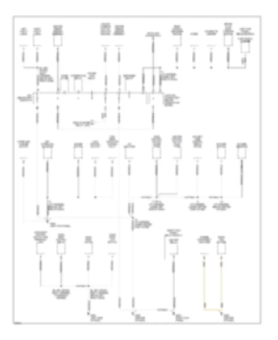
Ground Distribution Wiring Diagram (4 of 6) for Toyota Camry XLE 1995
List of elements for Ground Distribution Wiring Diagram (4 of 6) for Toyota Camry XLE 1995:
- * coupe only ** sedan/wagon
- **b2 *a2
- 1996 only
- 1mz-fe v6 only
- A/t indicator light
- A28
- A33
- A34
- All vehicles
- Auto antenna motor and relay
- B11 (or b27) (body harness, inside right front door)
- B38 (body harness, inside lift- gate assembly)
- Back door lock control switch (wagon)
- C16
- Combination meter
- D from g999
- D12
- D13
- Data link connector 1
- Data link connector 2
- Data link connector 3
- Door lock control relay
- E12 (engine harness, right rear corner of engine)
- E14 (engine harness, left end of engine)
- Engine control module
- From right front door lock control switch
- Fuel sender
- G115 (center rear of engine)
- G115 (right rear of engine)
- G200 (left kick panel)
- G203 (right kick panel)
- G406 (center of lift gate)
- G406 (right side of liftgate)
- G408 (center front of trunk)
- G998 (right rear 'd' pillar)
- Glove box light switch
- High mounted stop light
- I18 (i/p harness, behind lower right side of dash)
- I7 (i/p harness, under left dash cover)
- I9 (i/p harness, behind center of dash)
- Igniter
- J/b 3 (behind combination meter)
- Junction connector 2 (behind right side of i/p)
- Junction connector 7 (behind right side of i/p)
- Left rear combination light
- License plate light
- Luggage compartment light switch
- Nca
- Noise filter (ignition system)
- Over drive main switch
- Oxygen sensor (bank 1 sensor 1)
- Oxygen sensor (bank 1 sensor 2)
- Oxygen sensor (bank 2 sensor 1)
- Passenger power seat switch
- Rear window defogger (coupe/ sedan)
- Rear window defogger (wagon only)
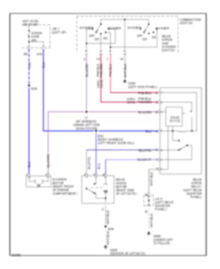
- Rear wiper motor
- Remote control mirror switch
- Rheostat
- Right belt buckle switch
- Right door key lock/ unlock switch
- Right rear combination light
- Shift lock ecu
- Wagon only
Ground Distribution Wiring Diagram (5 of 6) for Toyota Camry XLE 1995
List of elements for Ground Distribution Wiring Diagram (5 of 6) for Toyota Camry XLE 1995:
- * coupe only ** sedan/wagon
- **b2 *a2
- 1995 only
- 1mz-fe v6 only
- A/t indicator light
- A28
- A33
- A34
- All vehicles
- Auto antenna motor and relay
- B11 (or b27) (body harness, inside right front door)
- B38 (body harness, inside lift- gate assembly)
- Back door lock control switch (wagon)
- C16
- Combination meter
- D from g999
- D12
- D13
- Data link connector 1
- Data link connector 2
- Data link connector 3
- Door lock control relay
- E14 (engine harness, left end of engine)
- Engine control module
- From right front door lock control switch
- Fuel sender
- G115 (center rear of engine)
- G115 (right rear of engine)
- G200 (left kick panel)
- G203 (right kick panel)
- G406 (center of liftgate)
- G406 (right side of liftgate)
- G408 (center front of trunk)
- G998 (right rear 'd' pillar)
- Glove box light switch
- High mounted stop light
- I7 (i/p harness, under left dash cover)
- I9 (i/p harness, behind center of dash)
- Igniter
- J/b 3 (behind combination meter)
- Junction connector 2 (behind right side of i/p)
- Junction connector 7 (behind right side of dash)
- Left rear combination light
- License plate light
- Luggage compartment light switch
- Nca
- Noise filter (ignition system)
- Over drive main switch
- Oxygen sensor (bank 1 sensor 1)
- Oxygen sensor (bank 2 sensor 1)
- Passenger power seat switch
- Rear window defogger (coupe/ sedan)
- Rear window defogger (wagon only)
- Rear wiper motor
- Remote control mirror switch
- Rheostat
- Right belt buckle switch
- Right door key lock/ unlock switch
- Right rear combination light
- Shift lock ecu
- Wagon only
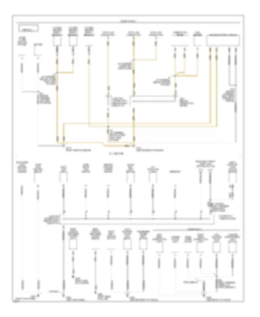
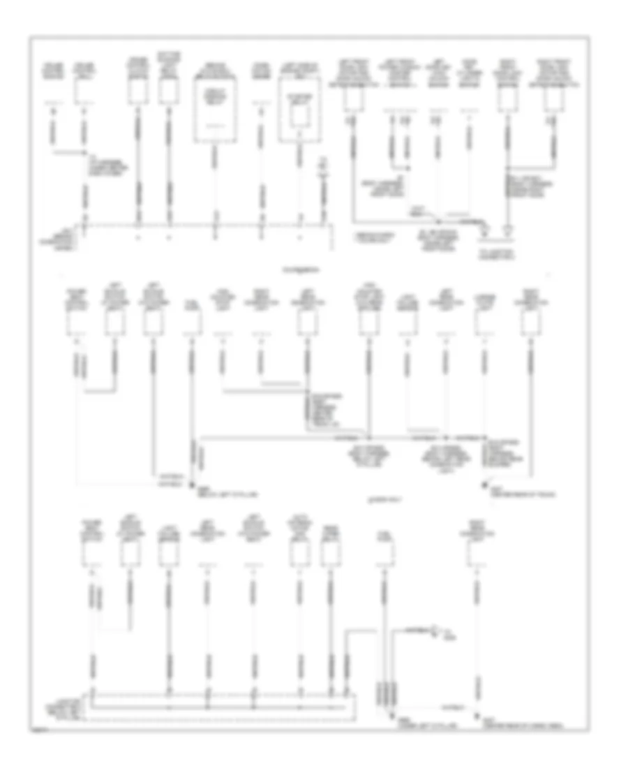
Ground Distribution Wiring Diagram (6 of 6) for Toyota Camry XLE 1995
List of elements for Ground Distribution Wiring Diagram (6 of 6) for Toyota Camry XLE 1995:
- (behind glove box) relay block 6
- (left side of engine compt) j/b 2
- * sedan/wagon ** coupe only
- **b2 *a2
- **b4 *a1
- **b6 *a2
- *a1 **b4
- A12
- A13
- Auto antenna motor and relay
- B1 (body harness, inside left front door)
- B1, (b2 or b18) body harness, inside left front door)
- B10 (or b25) (body harness, below left 'd' pillar)
- B11 (or b27) (body harness, inside right front door)
- B14
- B14 (or b28) (body harness, behind left rear combination light)
- B15 (or b28) (body harness, behind rear bumper)
- B16 (or b29) (body harness, center rear of trunk lid)
- C18
- Circuit opening relay
- Combi- nation meter
- Coupe/sedan
- Cruise control clutch switch
- Cruise control ecu
- Cruise control switch
- Daytime running light relay (main)
- Door key cylinder light & switch
- Fuel pump
- G407 (center rear of cargo area)
- G407 (center rear of trunk)
- G999 (below left 'd' pillar)
- G999 (under left 'd' pillar)
- High mounted stop light
- High mounted stop light (w/o rear spoiler)
- I13 (i/p harness, under center dash cover)
- J/b 3 (behind combination meter)
- Junction connector 5 (below left 'd' pillar)
- Left buckle switch (w/ power seat)
- Left buckle switch (w/o power seat)
- Left door key lock/ unlock switch
- Left front door lock motor and door unlock detection switch
- Left front power window master control switch
- Left rear combination light
- License plate light
- Light failure sensor
- Power seat control switch
- Rear wiper relay
- Right front door lock control switch
- Right front door lock motor and door unlock detection switch
- Right rear combination light
- Starter relay
- To g406
- To j/b 1
- To junction connector 2
- Wagon only
HEADLIGHTS
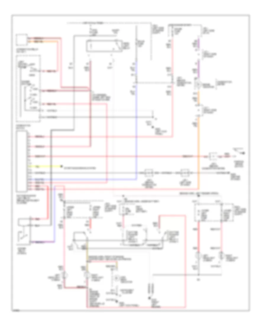
Headlight Wiring Diagram, with DRL for Toyota Camry XLE 1995
List of elements for Headlight Wiring Diagram, with DRL for Toyota Camry XLE 1995:
- (engine harn, front of engine compartment above grille opening) e4
- (engine harn, left fender apron) e7
- A10
- A12
- A17
- A18
- B11
- B12
- B13
- B14
- Brake indicator
- C11
- C18
- Combination meter
- Combination switch
- Daytime running light relay (behind instrument cluster)
- Daytime running light relay 3 (in r/b 7)
- Daytime running light relay 4 (in r/b 7)
- Dimmer relay (in r/b 5)
- Dimmer switch
- Drl fuse 5a
- E4 (engine harness, front of engine compt above grille opening)
- E6 (engine harn, under battery)
- Ecu-b fuse 15a
- Flash
- G100 (front left fender)
- G200 (left kick panel)
- G206 (center of dash)
- Gauge fuse 10a
- Head
- Head- light relay
- High
- High beam indicator
- Hot at all times
- Hot in on or start
- I7 (i/p harness, under left end of dash cover)
- Instrument cluster
- Integration relay (on j/b 1)
- J/b 1 (left side of dash)
- J/b 1 (left side of i/p)
- J/b 2 (left side of engine compt)
- J/b 3 (behind combination meter)
- J/c 1 (right side of dash)
- Left headlight hi beam
- Left headlight lo beam
- Light control switch
- Lower left head fuse 15a
- Lower right head fuse 15a
- Main fuse 40a
- Off
- Parking brake switch
- R/b 5 (left side of engine compt)
- R/b 7 (near battery)
- Red
- Right headlight hi beam
- Right headlight lo beam
- Short pin
- Starting/charging system
- Tail
- Upper left head fuse 15a
- Upper right head fuse 15a
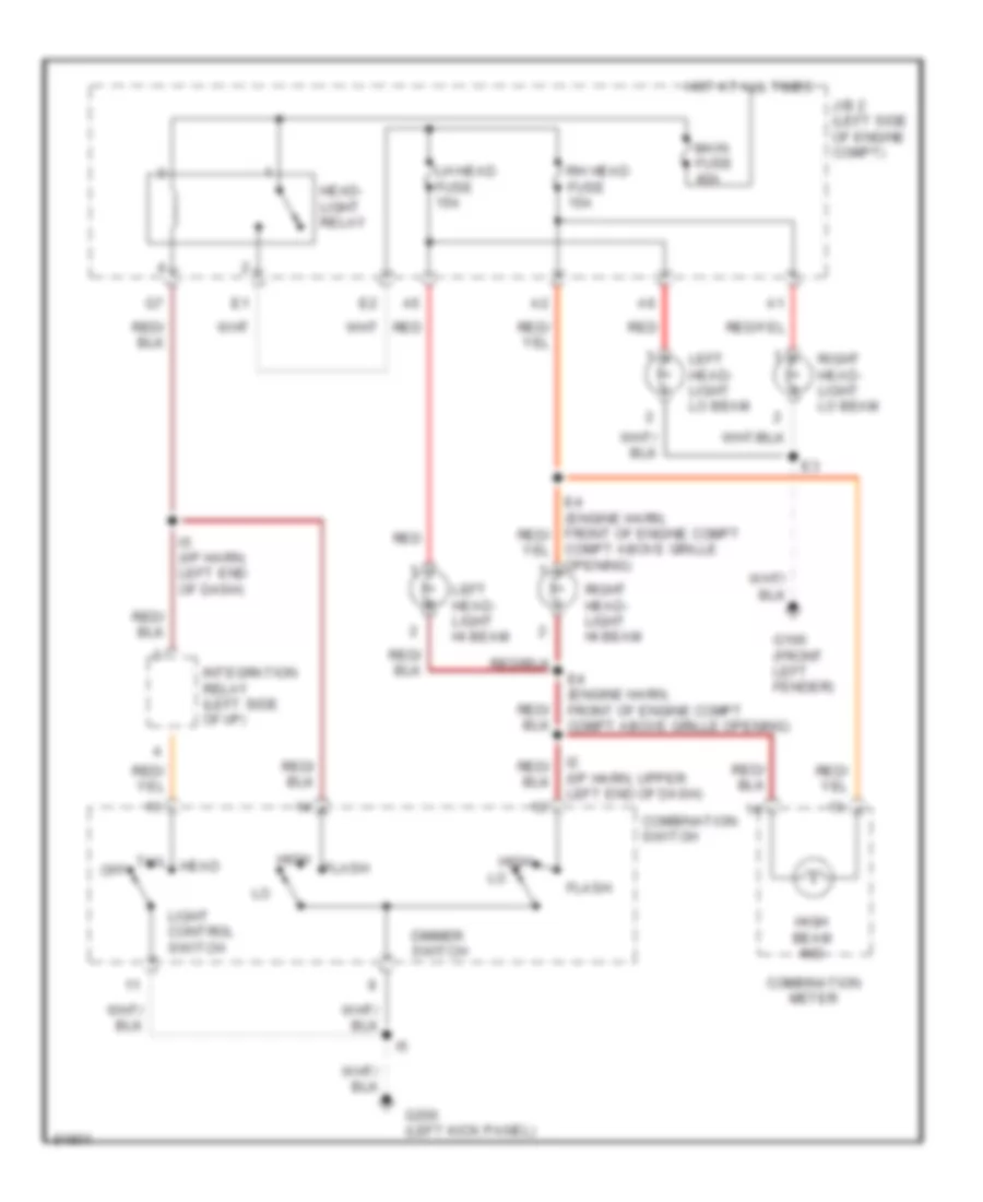
Headlight Wiring Diagram, without DRL for Toyota Camry XLE 1995
List of elements for Headlight Wiring Diagram, without DRL for Toyota Camry XLE 1995:
- (i/p harn, upper left end of dash)
- Combination meter
- Combination switch
- Compt above grille opening)
- Dimmer switch
- E4 (engine harn, front of engine compt compt above grille opening)
- Flash
- G100 (front left fender)
- G200 (left kick panel)
- Head
- Head- light relay
- High
- High beam ind
- Hot at all times
- I5 (i/p harn, left end of dash)
- Integration relay (left side of i/p)
- J/b 2 (left side of engine compt)
- Left head- light hi beam
- Left head- light lo beam
- Lh head fuse 15a
- Light control switch
- Main fuse 40a
- Off
- Red
- Rh head fuse 15a
- Right head- light hi beam
- Right head- light lo beam
- Tail
HORN
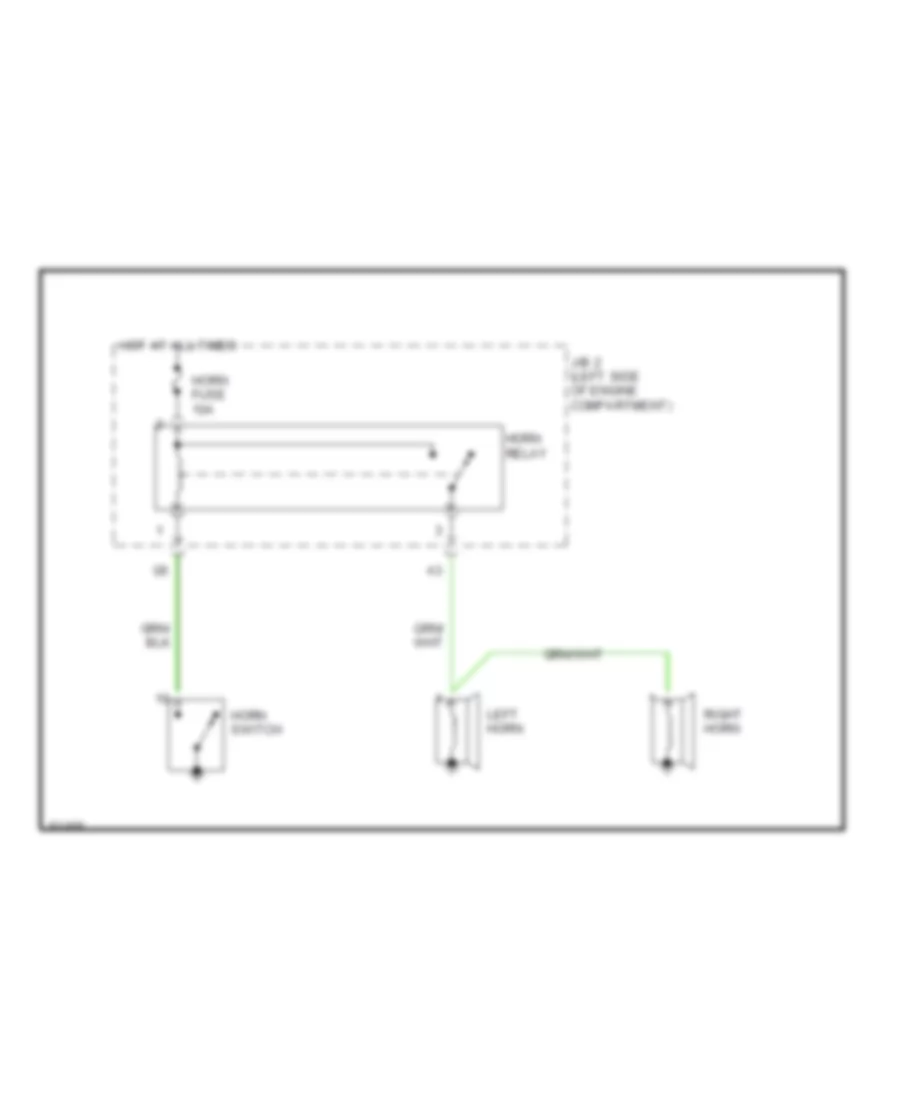
Horn Wiring Diagram for Toyota Camry XLE 1995
List of elements for Horn Wiring Diagram for Toyota Camry XLE 1995:
- Horn fuse 10a
- Horn relay
- Horn switch
- Hot at all times
- J/b 2 (left side of engine compartment)
- Left horn
- Right horn
INSTRUMENT CLUSTER
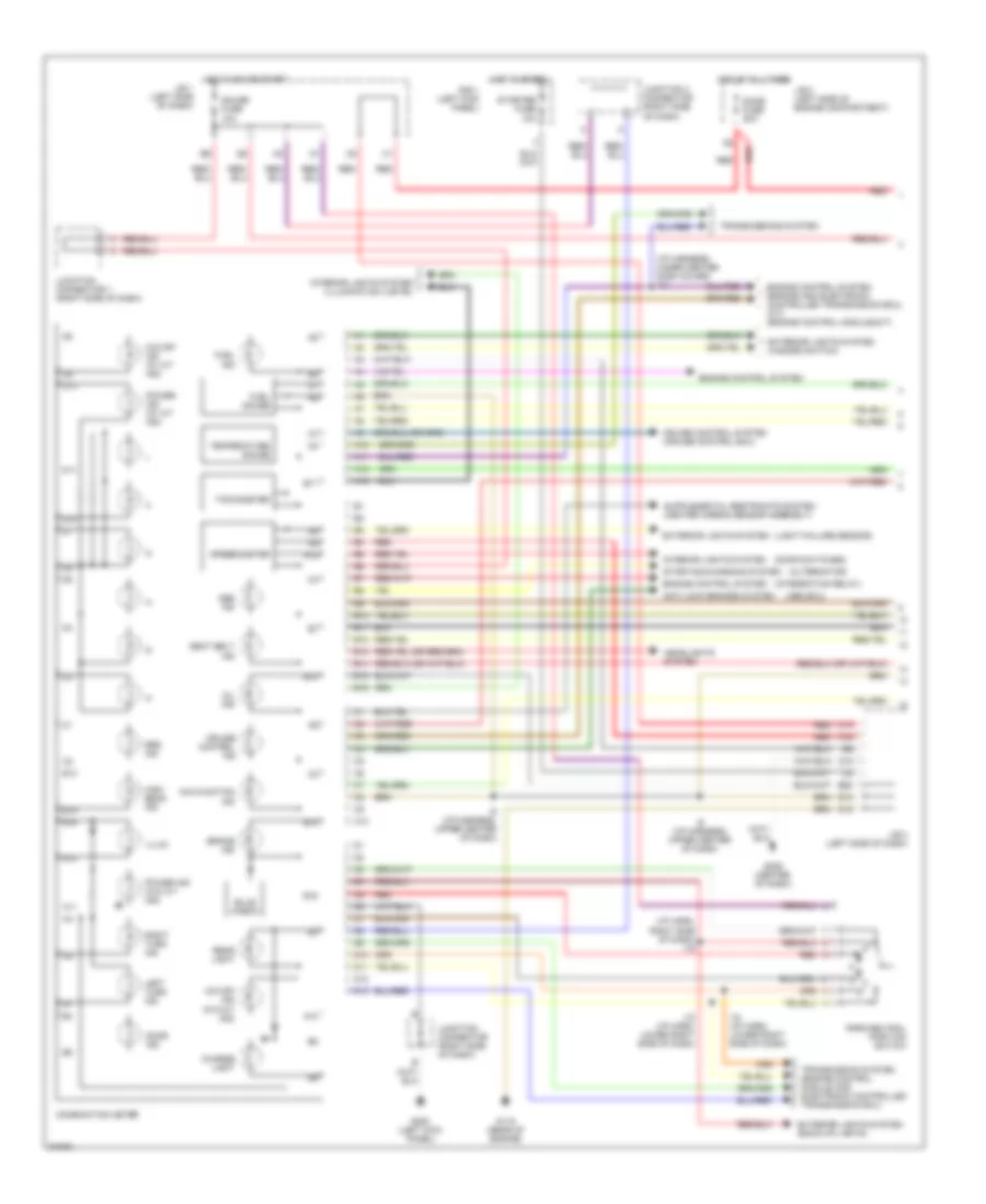
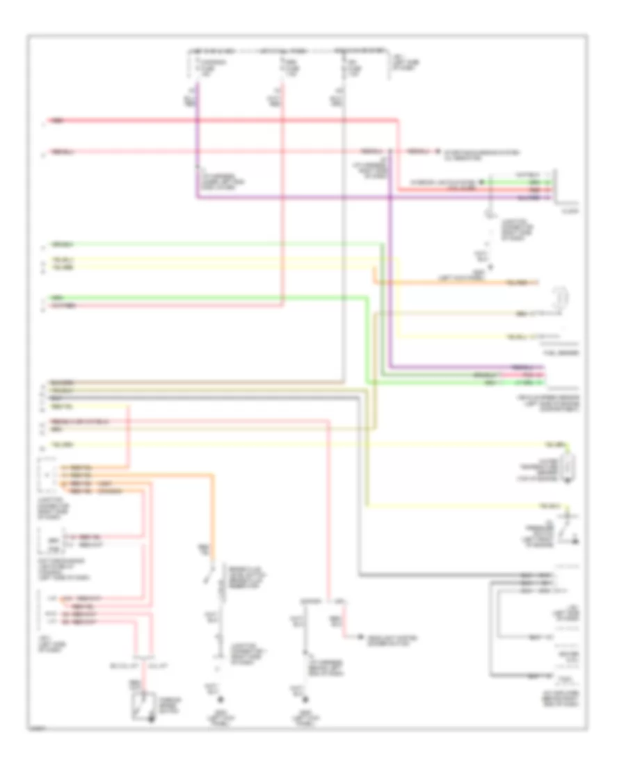
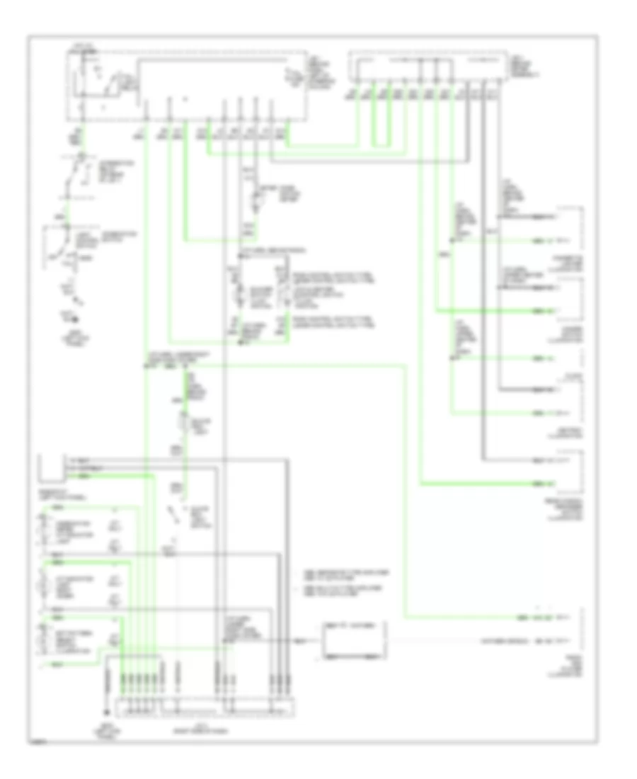
Instrument Cluster Wiring Diagram (1 of 2) for Toyota Camry XLE 1995
List of elements for Instrument Cluster Wiring Diagram (1 of 2) for Toyota Camry XLE 1995:
- (abs ecu)
- (alternator)
- (door switches)
- (i/p harn, right side of dash) i19
- (i/p harness, under center dash cover) i13
- (integration relay)
- (light failure sensor)
- A10
- A11
- A12
- A13
- A16
- Abs ind
- Anti-lock brakes system
- B10
- B11
- B12
- B13
- B14
- B15
- B16
- B20
- Brake ind
- Bulb check
- C10
- C14
- C18
- Charge light
- Combination meter
- Cruise control ind
- Cruise control system (cruise control ecu)
- D10
- D11
- D12
- D13
- Dome fuse 20a
- Door ind
- Engine control system
- Engine control system (engine and electronic controlled transmission ecu) (a/t) (engine control module)(m/t)
- Exterior lights system
- Exterior lights system (back-up lights)
- Exterior lights system (hazard switch)
- Fuel gauge
- Fuel ind
- G115 (rear of engine)
- G200 (left kick panel)
- G206 (center of dash)
- Gauge fuse 10a
- Headlights system
- High beam ind
- Hot at all times
- Hot in on or start
- Hot in start
- I18 (i/p harn, lower right side of dash)
- I9 (i/p harness, upper center of dash)
- Illum
- Interior lights system
- Interior lights system (illumination lights)
- J/b 1 (left side of dash)
- J/b 2 (left side of engine compartment)
- J/b 3 (left side of dash)
- Junction 3 connector (right side of dash)
- Junction connector (right side of dash)
- Junction connector 1 (right side of dash)
- Left turn ind
- Malfunction ind
- O/d off ind (w/ a/t ind)
- O/d off ind (w/o a/t ind)
- Oil ind
- Park/neutral position switch
- Power ind (w/ a/t ind)
- Power ind (w/o a/t ind)
- R/b 1 (left kick panel)
- Rear light
- Red
- Right turn ind
- Seat belt ind
- Speedometer
- Srs ind
- Starter fuse 10a
- Starting/charging system
- Tachometer
- Temperature gauge
- Transmission system (engine control module and electronic controlled transmission ecu)
- Transmissions system
Instrument Cluster Wiring Diagram (2 of 2) for Toyota Camry XLE 1995
List of elements for Instrument Cluster Wiring Diagram (2 of 2) for Toyota Camry XLE 1995:
- (canada)
- (usa)
- 3.0l a/t
- A/c amplifier (behind right end of dash)
- A10
- Brake fluid level switch (brake fluid reservoir)
- Brk
- Canada
- Cig/radio fuse 15a
- Clock
- D12
- D13
- Daytime running lights relay (canada) (left side of dash)
- Ex 3.0l a/t
- Fuel sender
- G200 (left kick panel)
- Headlight system (dimmer switch)
- Hot at all times
- Hot in on & acc
- Hot in on or start
- I27 (i/p harness, right side of dash)
- I5 (i/p harness, behind left end of dash)
- I7 (i/p harness, under left end dash cover)
- Ign fuse 7.5a
- Igniter (2.2l)
- Interior lights system (tail fuse)
- J/b 1 (left side of dash)
- J/b 3 (left side of dash)
- Junction connector (right side of dash)
- Junction connector 1 (right side of dash)
- Oil pressure switch (left front of engine)
- Parking brake switch
- Pkb
- Pnk
- Red
- Srs fuse 7.5a
- Starting/charging system (alternator)
- Tach
- Usa
- Vehicle speed sensor (left side of engine compartment)
- Water temperature sender (top of engine)
INTERIOR LIGHTS
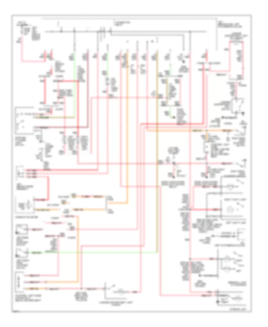
Courtesy Lamps Wiring Diagram, with Illuminated Entry for Toyota Camry XLE 1995
List of elements for Courtesy Lamps Wiring Diagram, with Illuminated Entry for Toyota Camry XLE 1995:
- (body harn, red inside left front door) b18
- (body harn, right front of roof) (wgn) b39
- (i/p harn, right end of dash)
- (i/p harn, under left end of dash) i6
- (i/p harn, under right side dash cover)
- (sdn) b4 (cp) b20 (body harn, above left front door)
- (sdn) b4 b30 (wgn) (body (cp) b20 (body harn, harn, above left front door)
- (sdn) b4 b31 (wgn) (body harn, (cp) b20 (body center of windshield header)
- A red
- A16
- Above left front door)
- B34 (body harn, left rear door sill)
- B38 (wgn) (body harn, center of tailgate)
- C1 red
- C14
- C5 red
- Combination meter
- Coupe
- Courtesy light diode (cp/sdn: center of i/p; wgn: below driver's seat)
- Courtesy light diode (wagon only) (below driver's seat)
- Cp & sdn only
- Cp only
- D14
- Dome fuse 20a
- Door
- Door key cylinder light/ switch
- Door locks system (door lock control relay)
- Door open ind
- Ex coupe
- Ex cp
- Ex wagon
- Ex wgn
- G200 (left kick panel)
- G206 (center of dash)
- G406 (center of liftgate)
- G902 (left side of roof)
- H6 red
- Harn, above left front door)
- Hot at all times
- I1 red
- I22
- I8 (i/p harn, right kick panel)
- Ign- tion key cyl- inder light
- Integration relay
- Interior light
- J/b 1 (behind dash, left of steering column)
- J/b 1 (left of steering column)
- J/b 2 (on left side of engine compt)
- J/b 3 (behind meter assembly)
- J/c 2 (under right side of dash)
- J/c 3 (behind right side of dash)
- K12 red a
- Left
- Left front door cour- tesy light
- Left front door courtesy switch
- Left rear door courtesy switch
- Left vanity light
- Luggage compartment light (ex wagon)
- Luggage compartment light (wagon)
- Luggage compartment light switch
- Off
- Personal light (w/ moonroof)
- Red
- Red i16
- Right
- Right front door cour- tesy light
- Right front door courtesy switch
- Right rear door courtesy switch
- Right vanity light
- Sdn
- Sdn & cp only
- Sdn & wgn only
- Tmc made
- Tmm made
- Wagon
- Wgn
- Wgn only
Courtesy Lamps Wiring Diagram, without Illuminated Entry for Toyota Camry XLE 1995
List of elements for Courtesy Lamps Wiring Diagram, without Illuminated Entry for Toyota Camry XLE 1995:
- (body harn, above left front door) b4 (sdn) b20 (cp)
- (i/p harn, right end of dash)
- (i/p harn, right kick panel) (sdn/cp) i24
- (i/p harn, under left end of dash) i6
- (i/p harn, under right side dash cover)
- A red
- A16
- B34 (body harn, left rear door sill)
- B38 (wgn) (body harn, center of tailgate)
- B39 (wgn) (body harn, right front of roof)
- C1 red
- C14
- C5 red
- Combination meter
- Courtesy light diode (cp/sdn: center of i/p; wgn: below driver's seat)
- Courtesy light diode (wagon only) (below driver's seat)
- Cp only
- D14
- Dome fuse 20a
- Door
- Door locks system (door lock control relay)
- Door open ind
- Ex cp
- Ex wagon
- Ex wgn
- G206 (cntr of dash)
- G406 (center of liftgate)
- G902 (left side of roof)
- H6 red
- Hot at all times
- I1 red
- I16
- I24 (i/p harn, right kick panel)
- Ignition key cyl- inder light
- Integration relay
- Interior light
- J/b 1 (behind dash, left of steering column)
- J/b 2 (on left side of engine compartment)
- J/b 3 (behind meter assembly)
- J/c 3 (behind right side of dash)
- Left
- Left front door courtesy light
- Left front door courtesy switch
- Left rear door courtesy switch
- Luggage compartment light (ex wagon)
- Luggage compartment light (wagon)
- Luggage compartment light switch
- Off
- Personal light (w/ moonroof)
- Red
- Right
- Right front door courtesy light
- Right front door courtesy switch
- Right rear door courtesy switch
- Sdn & cp only
- Sdn & wgn only
- Sedan
- Tmc made
- Tmm made
- Wagon
- Wgn
- Wgn only
Instrument Illumination Wiring Diagram for Toyota Camry XLE 1995
List of elements for Instrument Illumination Wiring Diagram for Toyota Camry XLE 1995:
- (i/p harn, behind center of dash) i12
- (i/p harn, behind radio) i14
- (i/p harn, under right side dash cover) i16
- (i/p harn, upper center of dash) i9
- (push control switch type) (lever control switch type)
- 1996: built-in type amplifier 1995: w/o cd player
- 1996: separate type amplifier 1995: w/ cd player
- A/c & heater control switch illum- ination
- A/t indicator light (shift lever)
- A/t only
- A10
- A13
- A15 b3
- Ashtray illumination
- B16
- Blower switch illum- ination
- Cigarette lighter illumination
- Clock
- Comb- ination meter
- Combination meter a/t indicator light
- Combination switch
- Ect pattern select switch illumination
- G200 (left kick panel)
- Glove box light
- Glove box light switch
- Hazard switch illumination
- Head
- Hot at all times
- Integration relay (on rear of j/b 1)
- J/b 1 (behind dash, left of steering column)
- J/b 3 (behind meter assembly)
- J/c 2 (right side of dash)
- Light control switch
- Meter ill
- Off
- Radio and player illumination
- Radio) i14
- Rear window defogger switch illumination
- Rheostat (left kick panel)
- Tail
- Tail fuse 15a
- Tail- light relay
PASSIVE RESTRAINTS
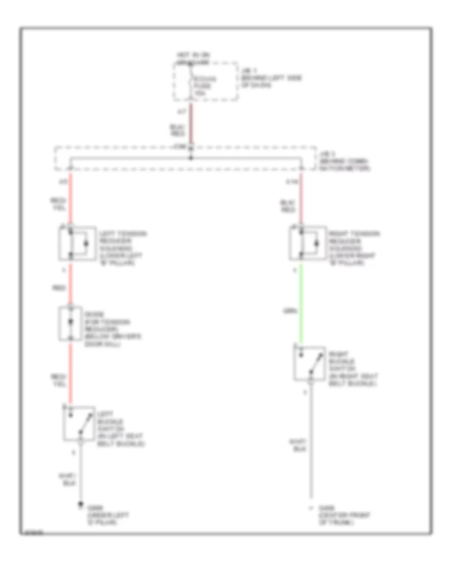
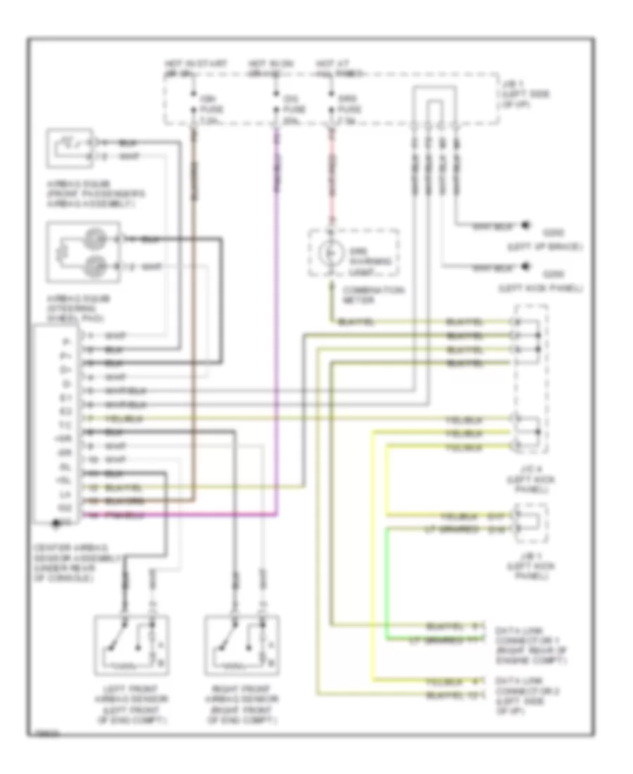
Passive Restraint Wiring Diagram for Toyota Camry XLE 1995
List of elements for Passive Restraint Wiring Diagram for Toyota Camry XLE 1995:
- A14
- C16
- Diode (for tension reducer) (below driver's door sill)
- Ecu-ig fuse 15a
- G408 (center front of trunk)
- G999 (under left 'd' pilar)
- Hot in on or start
- J/b 1 (behind left side of dash)
- J/b 3 (behind combi- nation meter)
- Left buckle switch (in left seat belt buckle)
- Left tension reducer solenoid (lower left "b" pillar)
- Red
- Right buckle switch (in right seat belt buckle)
- Right tension reducer solenoid (lower right "b" pillar)
POWER ANTENNA
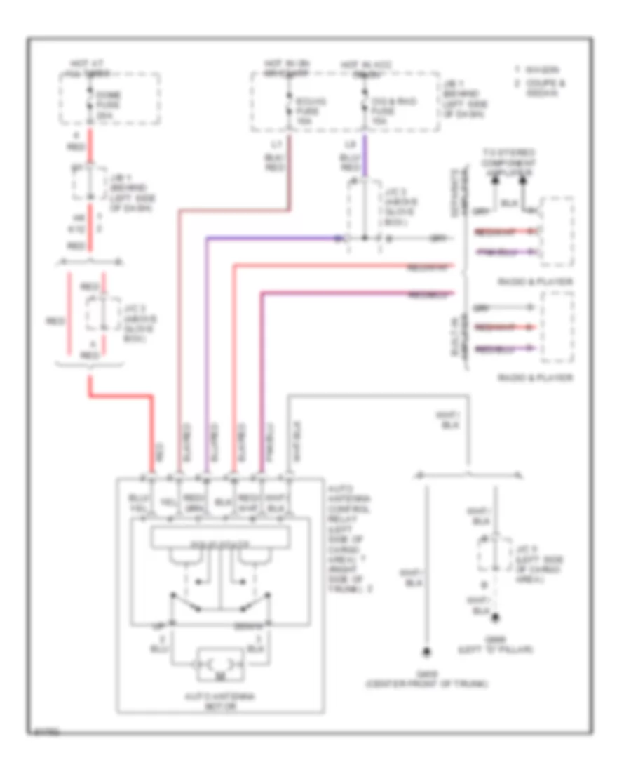
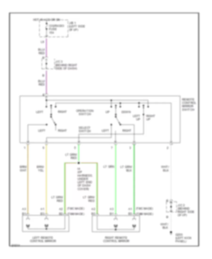
Power Antenna Wiring Diagram for Toyota Camry XLE 1995
List of elements for Power Antenna Wiring Diagram for Toyota Camry XLE 1995:
- Auto antenna control relay (left side of cargo area) (right side of trunk)
- Auto antenna motor
- Built-in amplifier
- Cig & rad fuse 15a
- Coupe & sedan
- Dome fuse 20a
- Down
- Ecu-ig fuse 10a
- G408 (center front of trunk)
- G999 (left "d" pillar)
- Hot at all times
- Hot in acc or on
- Hot in on or start
- J/b 1 (behind left side of dash)
- J/c 3 (above glove box)
- J/c 5 (left side of cargo area)
- K12
- Radio & player
- Red
- Separate amplifier
- Solid state
- To stereo component amplifier
- Wagon
POWER DISTRIBUTION
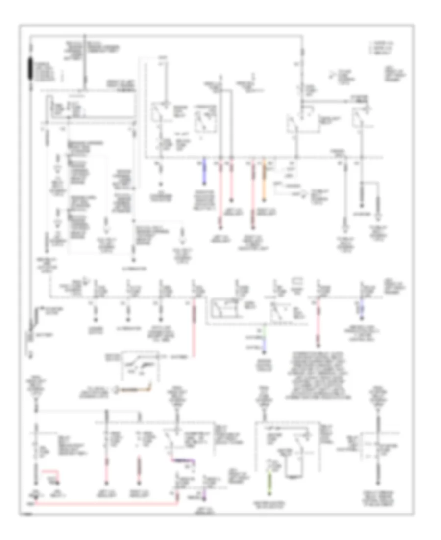
Power Distribution Wiring Diagram (1 of 2) for Toyota Camry XLE 1995
List of elements for Power Distribution Wiring Diagram (1 of 2) for Toyota Camry XLE 1995:
- (2.2l only) to j/b 1 (diagram 2 of 2)
- (3.0l only) to j/b 1 (diagram 2 of 2)
- (engine harn, left end of engine) e20 (2.2l)
- (engine harness, under battery) e22 (2.2l)
- (front of left front fender) fuse box
- 1mz-fe: 3.0l
- 5s-fe: 2.2l
- A/c condenser fan motor
- A/c fuse 40a
- A2 red
- A5 red
- A6 red
- Abs ecu (usa production only),
- Abs fuse 60a
- Abs relay, abs actuator & ecu
- Acc
- Alt fuse 120a 100a
- Alt-s fuse 7.5a
- Alternator
- Am2 fuse 30a
- Battery
- Canada
- Canada only
- Cds fuse 30a
- Circuit opening relay, engine control module, i/p (bulb check)
- Control ecu
- Cruise
- Data link connector 3 (except 5s-fe: 3.0l 1995)
- Dimmer relay (1995) drl relay 2 (1996)
- Dome fuse 20a
- Drl fuse 5a
- Drl relay 3
- Drl relay 4
- E12 (3.0l only) (engine harness, top right rear of engine)
- E14 (3.0l) (engine harness, left end of engine)
- E24 (2.2l) (engine harness, under battery)
- E8 (3.0l) (engine harness, under battery)
- Ecu-b fuse 15a
- Efi fuse 15a
- Efi main relay
- Engine control module
- Engine main relay
- From alt fuse (diagram 1 of 2)
- From d main 1 fuse (diagram 1 of 2)
- From headlight relay (diagram 1 of 2)
- From starter relay (diagram 1 of 2)
- Haz fuse 10a
- Hazard switch
- Head (l) fuse 15a
- Head (lwr-l) fuse 15a
- Head (lwr-r) fuse 15a
- Head (r) fuse 15a
- Headlight relay
- Heater control or a/c switch
- Heater fuse 40a
- Heater relay
- Horn fuse 10a
- Horn relay
- I996 only
- Ignition switch
- Integration relay, clock, moon roof control relay, luggage compartment light, open door warning light, ignition key cylinder light, interior light, personal light, left & right front door courtesy lights, door key cylinder light & switch, left & right vanity lights, automatic antenna & relay, stereo amplifier, radio & player.
- J/b 2 (front of left front fender)
- Left (hi) headlight
- Left (lo) headlight
- Main fuse 1 40a
- Nca
- Obd fuse 7.5a
- Off
- Radiator fan motor, radiator fan motor relay no. 3
- Radiator fan relay
- Rdi fan fuse 30a
- Red
- Relay box 1 (left kick panel)
- Relay box 4 (right kick panel)
- Relay box 5 (forward of left front shock tower)
- Relay box 7 (behind right headlight, near battery)
- Right (hi) headlight, hi beam indicator light
- Right (lo) headlight
- Short pin
- Start
- Starter
- Starter fuse 10a
- Starter motor
- Starter relay
- To haz fuse (diagram 1 of 2)
- To j/b 1 (diagram 2 of 2)
- To j/b no. 1 (ignition fuse) (diagram 2 of 2)
- To relay box 1 (diagram 1 of 2)
- To relay box 4 (diagram 1 of 2)
- To relay box 5 (diagram 1 of 2)
- To relay box 7 (diagram 1 of 2)
- Usa
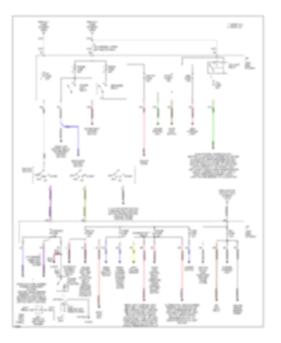
Power Distribution Wiring Diagram (2 of 2) for Toyota Camry XLE 1995
List of elements for Power Distribution Wiring Diagram (2 of 2) for Toyota Camry XLE 1995:
- 1mz-fe: 3.0l 5s-fe: 2.2l
- A10 pnk
- Acc
- Alternator, vehicle speed sensor, malfunction ind. light, speedometer, drl main relay, back-up light switch, rear window defogger switch, a/t indicator switch & light (o/d off)
- Ami fuse 40a
- Automatic antenna motor & relay
- Back door control switch
- Center airbag sensor assem.
- Charge warning light
- Cig/radio fuse 15a
- Cigar- ette lighter
- Clock
- Clutch start switch,
- Cruise control ecu
- Cruise control ecu, abs ecu & actuator, left & right tension reducer solenoid, radiator fan relay
- Defog fuse 40a
- Defogger relay
- Door lock control relay, elect. operated trans- mission pattern select switch
- Door lock control relay, power seat control switch
- Ecu-ig fuse 15a
- Efi main relay
- From alt fuse (diagram 1 of 2)
- From ignition switch, pin 9 (diagram 1 of 2)
- Front wiper/ washer switch, washer motor, front wiper motor
- G10
- G200 (left kick panel)
- Gauge fuse 10a
- Hazard switch
- I2 (i/p harness, upper left end of dash)
- Idle-up diode
- Idle-up diode, hazard switch, ashtray illumination, cigarette lighter illumination, rear defogger switch, blower switch, a/c-heater control switch, radio & player, a/t indicator lights, rheostat, glove box light, left & right front side marker/parking lights, license plate light, left & right rear side marker lights, light failure sensor, i/p illumination
- Ign fuse 7.5a
- Ignition coil(s), fuel injectors, igniter, noise filter
- Ignition switch
- Integration relay
- J/b (left side of dash)
- J/b 1 (front of left front fender)
- J/c 1 (behind left side of dash)
- Light failure sensor
- Mir htr fuse 10a
- Off
- Park/neutral position switch, engine control module, cruise control diode
- Pnk
- Power fuse 30a
- Power main relay
- Power seat control switch
- Radio & player, stereo stereo component amlifier, center airbag sensor assembly, automatic antenna motor & relay, remote control mirror switch, shift lock ecu
- Rear light warning light, seat belt warning light, abs warning light, heater relay & control switch, air inlet control servo motor (push type), air vent mode control servo motor, a/c magnetic clutch relay & dual pressure switch, i/p
- Rear wiper relay & motor
- Shift lock ecu
- Srs fuse 7.5a
- Srs warning light
- Start
- Stop fuse 15a
- Stop light switch
- Tail fuse 15a
- Taillight relay
- Turn fuse 7.5a
- Wiper fuse 20a
POWER DOOR LOCKS
Power Door Lock Wiring Diagram for Toyota Camry XLE 1995
List of elements for Power Door Lock Wiring Diagram for Toyota Camry XLE 1995:
- (i/p harn, left kick panel) i3
- (i/p harn, right side of i/p) i22
- (i/p harn, top right side of i/p) i16
- B1 (w/ pwr window) b2 (w/o pwr window) b18 (w/ pwr window, coupe) (door harn, in right front door)
- B11 (sdn/wgn) b27 (coupe) (door harn, in right front door)
- Back door lock control switch
- Back door lock motor (wagon)
- Coupe
- Door lock control relay (right side of i/p)
- G200 (left kick panel)
- G202 (left i/p brace)
- G203 (right kick panel)
- Gauge fuse 10a
- Hot at all times
- Hot in on or start
- I22 (i/p harn, right side of i/p)
- J/b 1 (left side of i/p)
- Junction connector j2 (right side of i/p)
- Junction connector j3 (right side of i/p) (tmc production vehicles a/t, tmm production vehicles)
- K11
- K14
- Left door key lock/ unlock switch
- Left door lock control switch
- Left front door courtesy switch
- Left front door lock motor/door unlock detection switch
- Left rear door lock motor
- Lock
- Lock timer
- Power fuse 30a
- Power main relay
- Power window
- Power windows system (power window master switch)
- Right door key lock/ unlock switch
- Right front door courtesy switch
- Right front door lock control switch
- Right front door lock motor/door unlock detection switch
- Right rear door lock motor
- Sdn/wgn
- Solid state
- Tmc production vehicles m/t
- Unlock
- Unlock timer
- Unlock warning switch (ignition switch)
- Wagon w/
- Wagon w/o
POWER MIRRORS
Power Mirror Wiring Diagram for Toyota Camry XLE 1995
List of elements for Power Mirror Wiring Diagram for Toyota Camry XLE 1995:
- (tmc made)
- (tmm made)
- Cig/radio fuse 15a
- Down
- G200 (left kick panel)
- Hot in acc or on
- I4 (i/p harness, under left end of dash cover)
- J/b 1 (left side of i/p)
- J/c 2 (behind right side of i/p)
- J/c 3 (behind right side of dash)
- Left
- Left remote control mirror
- Left up
- Operation switch
- Remote control mirror switch
- Right
- Right remote control mirror
- Right up
- Select switch
POWER SEATS
Driver Power Seat Wiring Diagram for Toyota Camry XLE 1995
List of elements for Driver Power Seat Wiring Diagram for Toyota Camry XLE 1995:
- power seat motor (driver's seat for reclining motor control)
- Coupe
- Down
- Except coupe
- G999 (under left "d" pillar)
- H20
- Hot at all times
- J/b 1 (left side of dash)
- J/c 5 (left side of engine compartment)
- Power fuse 30a
- Power seat control switch (driver's seat)
- Power seat motor (driver's seat for front vertical control)
- Power seat motor (driver's seat for rear vertical control)
- Power seat motor (driver's seat for slide control)
- Red
- Sedan & coupe
- Wagon
Passenger Power Seat Wiring Diagram for Toyota Camry XLE 1995
List of elements for Passenger Power Seat Wiring Diagram for Toyota Camry XLE 1995:
- (sedan only)
- G408 (center front of trunk)
- Hot at all times
- I22 (i/p harness, right end of dash)
- J/b 1 (left side of dash)
- Power fuse 30a
- Power seat control switch (passenger's seat)
- Power seat motor (passenger's seat reclining control)
- Power seat motor (passenger's seat slide control)
POWER TOP/SUNROOF
Power Top/Sunroof Wiring Diagrams for Toyota Camry XLE 1995
List of elements for Power Top/Sunroof Wiring Diagrams for Toyota Camry XLE 1995:
- B31 b21
- B32 b21
- Close
- Dome fuse 20a
- Door lock control relay (behind right side of dash)
- Down
- G206 (left dash brace)
- G902 (left side of roof)
- G908 (center back panel)
- Gauge fuse 10a
- Hot at all times
- Hot in on or start
- J/b 1 (left side of dash)
- J/b 2 (left side of engine compartment)
- J/c 3 (behind right side of dash)
- Moon roof control relay (front of roof)
- Moon roof control switch
- Moon roof limit switch (front of roof)
- Moon roof motor (front of roof)
- No.
- Open
- Pnk
- Power fuse 30a
- Power main relay
- Red
- Rly
- Sedan wagon coupe
- Solid state
- Usa production vehicles japan production vehicles m/t japan production vehicles a/t
POWER WINDOWS
Power Window Wiring Diagram for Toyota Camry XLE 1995
List of elements for Power Window Wiring Diagram for Toyota Camry XLE 1995:
- (body harn, left center pillar) b1
- (cpe)
- (sdn, wgn)
- B1 & b2 b18
- Coupe
- Door lock control relay (behind right side of i/p)
- Down
- G200 (left kick panel)
- G206 (left i/p brace)
- Gauge fuse 10a
- Hot at all times
- Hot in on or start
- I24 (i/p harness, below right side of i/p)
- I3 (i/p harn, left kick panel)
- J/b 1 (left side of i/p)
- J/c 2 (behind right side of i/p)
- J/c 3 (behind right side of i/p)
- K10
- K11
- Left front power window motor
- Left rear power window control switch
- Left rear power window motor
- Lock
- Normal
- Power fuse 30a
- Power main relay
- Power window master switch
- Red
- Right front power window control switch
- Right front power window motor
- Right rear power window control switch
- Right rear power window motor
- Rly
- Sedan & wagon
- Solid state
- Tmc production vehicles a/t
- Tmc production vehicles m/t
- Tmm production vehicles
RADIO
Radio Wiring Diagrams, Sedan with Built-In Amplifier for Toyota Camry XLE 1995
List of elements for Radio Wiring Diagrams, Sedan with Built-In Amplifier for Toyota Camry XLE 1995:
- Auto antenna motor & relay
- B10
- Cig/radio fuse 15a
- Dome fuse 20a
- G206 (right dash brace)
- Hot at all times
- Hot in acc or on
- J/b 1 (left side of dash)
- J/b 2 (left engine compartment)
- J/c 3 (upper right side of dash)
- K12
- Left front door speaker
- Left rear speaker
- Pnk
- Radio & player
- Red
- Right front door speaker
- Right rear speaker
Radio Wiring Diagrams, Sedan with Seperate Amplifier for Toyota Camry XLE 1995
List of elements for Radio Wiring Diagrams, Sedan with Seperate Amplifier for Toyota Camry XLE 1995:
- A10
- A11
- A12
- A13
- A14
- B10
- Cig/radio fuse 15a
- Dome fuse 20a
- G206 (right dash brace)
- Hot at all times
- Hot in acc or on
- I15
- J/b 1 (left side of dash)
- J/b 2 (left engine compartment)
- J/c 3 (upper right side of dash)
- K12
- Left front door speaker
- Left front tweeter speaker
- Left rear speaker
- Nca
- Pnk
- Power antenna system
- Radio & player
- Red
- Right front door speaker
- Right front tweeter speaker
- Right rear speaker
- Stereo component amplifier
Radio Wiring Diagrams, Wagon with Built-In Amplifier for Toyota Camry XLE 1995
List of elements for Radio Wiring Diagrams, Wagon with Built-In Amplifier for Toyota Camry XLE 1995:
- (front of left quarter panel)
- Auto antenna motor & relay
- B10
- Cig/radio fuse 15a
- Dome fuse 20a
- G206 (right dash brace)
- Hot at all times
- Hot in acc or on
- J/b 1 (left side of dash)
- J/b 2 (left side of engine compartment)
- J/c 3 (upper right side of dash)
- J/c 5
- K12
- Left front door speaker
- Pnk
- Red
- Right front door speaker
- Right rear door speaker
- Right rear tweeter speaker
- Stereo component amplifier
Radio Wiring Diagrams, Wagon with Seperate Amplifier for Toyota Camry XLE 1995
List of elements for Radio Wiring Diagrams, Wagon with Seperate Amplifier for Toyota Camry XLE 1995:
- (front of left quarter panel)
- A10
- A11
- A12
- A13
- A14
- B10
- Cig/radio fuse 15a
- Dome fuse 20a
- G206 (right dash brace)
- Hot at all times
- Hot in acc or on
- I15
- J/b 1 (left side of dash)
- J/b 2 (left side of engine compartment)
- J/c 3 (upper right side of dash)
- J/c 5
- K12
- Left front door speaker
- Left front tweeter speaker
- Nca
- Pnk
- Power antenna system
- Radio & player
- Red
- Right front door speaker
- Right front tweeter speaker
- Right rear door speaker
- Right rear tweeter speaker
- Stereo component amplifier
SHIFT INTERLOCKS
Shift Interlock Wiring Diagram for Toyota Camry XLE 1995
List of elements for Shift Interlock Wiring Diagram for Toyota Camry XLE 1995:
- Acc
- Cig & rad fuse 15a
- Ecu-ig fuse 15a
- G200 (left kick panel)
- Hot at all times
- Hot in acc or on
- Hot in on or start
- J/b 1 (left side of i/p)
- J/b 1 (left side of i/p)
- J/c 2 (right side of i/p)
- J/c 3 (right side of i/p)
- Key interlock solenoid (behind ign switch assembly)
- Kls+
- Shift lock control switch
- Shift lock ecu (under center of console)
- Shift lock solenoid
- Sls+
- Sls-
- Stop fuse 15a
- Stop light switch (behind left side of i/p)
- Stp
STARTING/CHARGING
2.2L
2.2L, Starting Wiring Diagram for Toyota Camry XLE 1995
List of elements for 2.2L, Starting Wiring Diagram for Toyota Camry XLE 1995:
- A/t
- Acc
- Alt fuse 100a
- Am1 fuse 40a
- Battery
- Battery ground
- Clutch start switch (behind left side of i/p)
- E22 (engine harness, under battery)
- E24 (engine harness, under battery)
- Engine controls system
- Fuse box (on left side of engine compt)
- G206 (center of dash)
- Gener- ator
- Ignition switch
- J/b 1 (behind dash, left of steering column)
- J/b 2 (on left side of engine compt)
- J/b 3 (behind meter assembly)
- M/t
- Main fuse 1 40a
- Nca
- Off
- P/ n
- Park/neutral position switch (on top of transaxle)
- R/b 1 (behind left kick panel)
- St relay
- Start
- Starter
- Starter fuse 10a
Charging Wiring Diagram for Toyota Camry XLE 1995
List of elements for Charging Wiring Diagram for Toyota Camry XLE 1995:
- (behind lower right side of dash, i/p harness) i18
- 100a
- 3.0 only
- Alt fuse 120a (3.0l) (2.2l)
- Alt-s fuse 7.5a
- Battery
- Battery ground
- Charge warning light
- Comb- ination meter
- Daytime running light relay main (canada) (behind dash, right of steering column)
- Fuse box (on left side of engine compt)
- Gauge fuse 10a
- Generator
- Hot at all times
- Hot in on or start
- Ign fuse 7.5a
- J/b (behind dash, left of steering column)
- J/b (on left side of engine compt)
- J/c (under left side of dash)
- Nca
- Vehicle speed sensor (on top of trans)
3.0L
3.0L, Starting Wiring Diagram for Toyota Camry XLE 1995
List of elements for 3.0L, Starting Wiring Diagram for Toyota Camry XLE 1995:
- (1995) (1996)
- (1996) (1995)
- Acc
- Alt fuse 120a
- Am1 fuse 40a
- Battery
- Battery ground
- E12 (engine harness, top right rear of engine)
- E8 (engine harness, under battery)
- Engine controls system
- Fuse box (on left side of engine compt)
- G206 (center of dash)
- Generator
- I18 (i/p harness, behind lower right side of dash)
- Ignition switch
- J/b 1 (behind dash, left of steering column)
- J/b 2 (on left side of engine compt)
- J/b 3 (behind meter assembly)
- Main fuse 1 40a
- Nca
- Off
- P/ n
- Park/neutral position switch (on top of transaxle)
- R/b 1 (behind left kick panel)
- St relay
- Start
- Starter
- Starter fuse 10a
Charging Wiring Diagram for Toyota Camry XLE 1995
List of elements for Charging Wiring Diagram for Toyota Camry XLE 1995:
- (behind lower right side of dash, i/p harness) i18
- 100a
- 3.0 only
- Alt fuse 120a (3.0l) (2.2l)
- Alt-s fuse 7.5a
- Battery
- Battery ground
- Charge warning light
- Comb- ination meter
- Daytime running light relay main (canada) (behind dash, right of steering column)
- Fuse box (on left side of engine compt)
- Gauge fuse 10a
- Generator
- Hot at all times
- Hot in on or start
- Ign fuse 7.5a
- J/b (behind dash, left of steering column)
- J/b (on left side of engine compt)
- J/c (under left side of dash)
- Nca
- Vehicle speed sensor (on top of trans)
SUPPLEMENTAL RESTRAINTS
Supplemental Restraint Wiring Diagram for Toyota Camry XLE 1995
List of elements for Supplemental Restraint Wiring Diagram for Toyota Camry XLE 1995:
- (left front of eng compt)
- (left i/p brace)
- (left kick panel)
- (right front of eng compt)
- +sl
- +sr
- -sl
- -sr
- Acc
- Airbag squib (front passenger's airbag assembly)
- Airbag squib (steering wheel pad)
- Center airbag sensor assembly (under rear of console)
- Cig fuse 15a
- Combination meter
- D16
- D17
- Data link connector 1 (right rear of engine compt)
- Data link connector 2 (left side of i/p)
- G200
- G202
- Hot at all times
- Hot in on or acc
- Hot in start or on
- Ig2
- Ign fuse 7.5a
- J/b 1 (left kick panel)
- J/b 1 (left side of i/p)
- J/c 4 (left kick panel)
- Left front airbag sensor
- Right front airbag sensor
- Srs fuse 7.5a
- Srs warning light
TRANSMISSION
2.2L
2.2L, Transmission Wiring Diagram for Toyota Camry XLE 1995
List of elements for 2.2L, Transmission Wiring Diagram for Toyota Camry XLE 1995:
- (1995)
- (1996)
- (behind right i/p)
- (brake pedal bracket) stop light switch
- (left kick panel)
- (left side of dash) i6
- (lockup)
- (right side of dash)
- (right side of dash) i18
- A/t indicator switch (left side of transaxle)
- A11
- A15
- Acc
- B/k
- Batt
- C19
- Conn a
- Conn b
- Conn c
- Cruise control ecu
- D10
- D11
- D12
- D13
- D22
- Data link connector 1 (right rear eng compt)
- Data link connector 2 (left i/p)
- E01
- E02
- E21
- Ect
- Efi fuse 15a
- Efi main relay
- Electronic controlled transmission pattern select switch
- Electronic controlled transmission solenoid
- Engine control module (behind right i/p)
- Engine controls
- Engine coolant
- Exterior lights system
- G100 (front of left front fender)
- G117 (left intake manifold)
- G117 (right intake manifold)
- G200 (left kick panel)
- Gauge fuse 15a
- Hot at all times
- Hot in on or start
- I18
- I18 (right side of dash)
- I3 (cntr of dash)
- I6 (left side of dash)
- Idl
- Ign fuse 7.5a
- Ignition switch
- Instrument cluster system (w/ a/t indicator)
- Interior lights system
- J/b 1 (left i/p)
- J/b 2 (left engine compt)
- J/b 3 (behind instrument cluster)
- J/c 1 (behind left i/p)
- J/c 2 (behind right i/p)
- J/c 3 (behind right i/p)
- No. 1
- No. 2
- No. 3
- Norm
- Nsw
- O/d main switch
- Od2
- Off
- Pwr
- Red
- Sp1
- St1
- Start
- Starting/ charging system
- Stop fuse 15a
- Temperature sensor (coolant outlet)
- Throttle position sensor (on throttle body assembly)
- Thw
- Vta
3.0L
3.0L, Transmission Wiring Diagram for Toyota Camry XLE 1995
List of elements for 3.0L, Transmission Wiring Diagram for Toyota Camry XLE 1995:
- (left kick panel)
- (left of intake manifold)
- (right rear of engine) dash)
- (right side of dash)
- A/t indicator switch (left side of transaxle)
- A11
- A15
- Batt
- C19
- Conn a
- Conn b
- Conn c
- Conn d
- Cruise control ecu (behind right i/p)
- D10
- D11
- D13
- D22
- Data link connector 1 (check connector) (right rear eng compt)
- E01
- E02
- E03
- E12
- Ect
- Efi fuse 15a
- Efi main relay
- Electronic controlled transmission pattern select switch
- Electronic controlled transmission solenoid
- Engine control module (behind right of i/p)
- Engine coolant
- G100 (front of left front fender)
- G117
- G200 (left kick panel)
- Gauge fuse 10a
- Hot at all times
- Hot in on or start
- I18
- I18 (right side of dash)
- I6 (under left end dash cover)
- Idl
- Ign fuse 7.5a
- Instrument cluster system (w/ a/t indicator)
- Interior lights system
- J/b 1 (left i/p)
- J/b 2 (left engine compt)
- J/b 3 (behind instrument cluster)
- J/c 1 (behind left i/p)
- J/c 2 (behind right i/p)
- J/c 3 (behind right i/p)
- J/c 7 (behind right i/p)
- J/c 8 (behind right i/p)
- Nc2+
- Nc2-
- Norm
- O/d direct clutch speed sensor (right eng compt)
- O/d main switch
- Od1
- Od2
- Pwr
- Red
- Sln-
- Sp1
- Starting/ charging system
- Stop fuse 15a
- Stop light switch (brake pedal bracket)
- Stp
- Te1
- Temperature sensor (coolant outlet)
- Throttle position sensor (on throttle body assembly)
- Thw
- Vta
WARNING SYSTEMS
Warning System Wiring Diagrams for Toyota Camry XLE 1995
List of elements for Warning System Wiring Diagrams for Toyota Camry XLE 1995:
- (w/ pwr seats)
- (w/o pwr seats)
- Buzzer
- Combination meter
- Coupe
- Dome fuse 20a
- G206 (center of dash)
- G999 (under left "c" pillar)
- Gauge fuse 10a
- Hot at all times
- Hot in on or start
- Integration relay
- J/b 1 (behind left side of dash)
- J/b 2 (left side of engine compartment)
- J/c 1 (behind left side of dash)
- J/c 5 (left side of cargo area)
- Left buckle switch
- Left front door courtesy switch (in left "b" pillar)
- Power seat switch
- Red
- Seat belt
- Sedan &
- Solid state
- Unlock warning switch (ignition switch) (on steering column, part of ignition switch assembly)
- Wagon
WIPER/WASHER
Front Wiper/Washer Wiring Diagram for Toyota Camry XLE 1995
List of elements for Front Wiper/Washer Wiring Diagram for Toyota Camry XLE 1995:
- Behind left end of dash) i5
- Combination switch
- E4 (engine harness, front of engine compartment, above grille opening)
- Fender apron)
- Front wiper and washer switch
- Front wiper motor (right rear of engine compartment)
- G100 (front of left front fender)
- G101 (front of right front fender)
- G200 (left kick panel)
- Hot in on or start
- Int
- J/b 1 (left i/p)
- Mist
- Off
- Solid state
- Wash
- Washer motor (right front of engine compartment)
- Wiper fuse 20a
Rear Wiper/Washer Wiring Diagram for Toyota Camry XLE 1995
List of elements for Rear Wiper/Washer Wiring Diagram for Toyota Camry XLE 1995:
- (usa) (can)
- B36 (body harness, left front door sill)
- B38
- Combination switch
- G200 (left kick panel)
- G406 (center of liftgate)
- G999 (under left "d" pillar)
- H15
- Hot in on or start
- I7 (i/p harness, under left end dash cover)
- Int
- J/b 1 (left i/p)
- J/c 5 (left rear quarter panel)
- Off
- On int
- Rear wiper and washer switch
- Rear wiper motor (right side of liftgate)
- Rear wiper relay (left rear quarter panel)
- Solid state
- Washer
- Washer motor (right front of engine compartment)
- Wiper fuse 20a

 Čeština
 Dansk
Dansk Deutsch
 Ελληνικά
 English
 English
 Español
 Français
 Français
 עברית
עברית Hrvatski
 Magyar
 Italiano
 日本語
日本語 한국어
한국어 Nederlands
 Polski
 Português
 Português
 Română
 Русский
 Slovenčina
 Slovenščina
 Svenska
 Türkçe
 中文 (中国)