AIR CONDITIONING
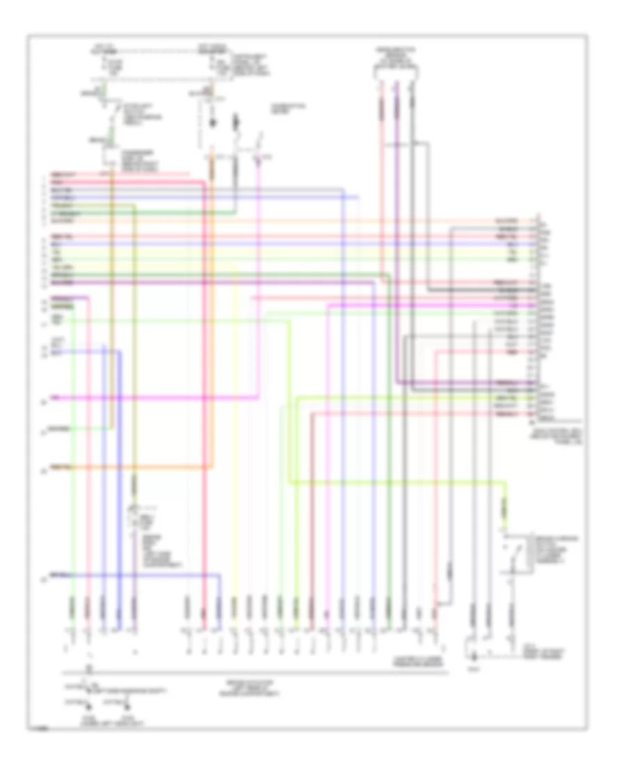
2.4L
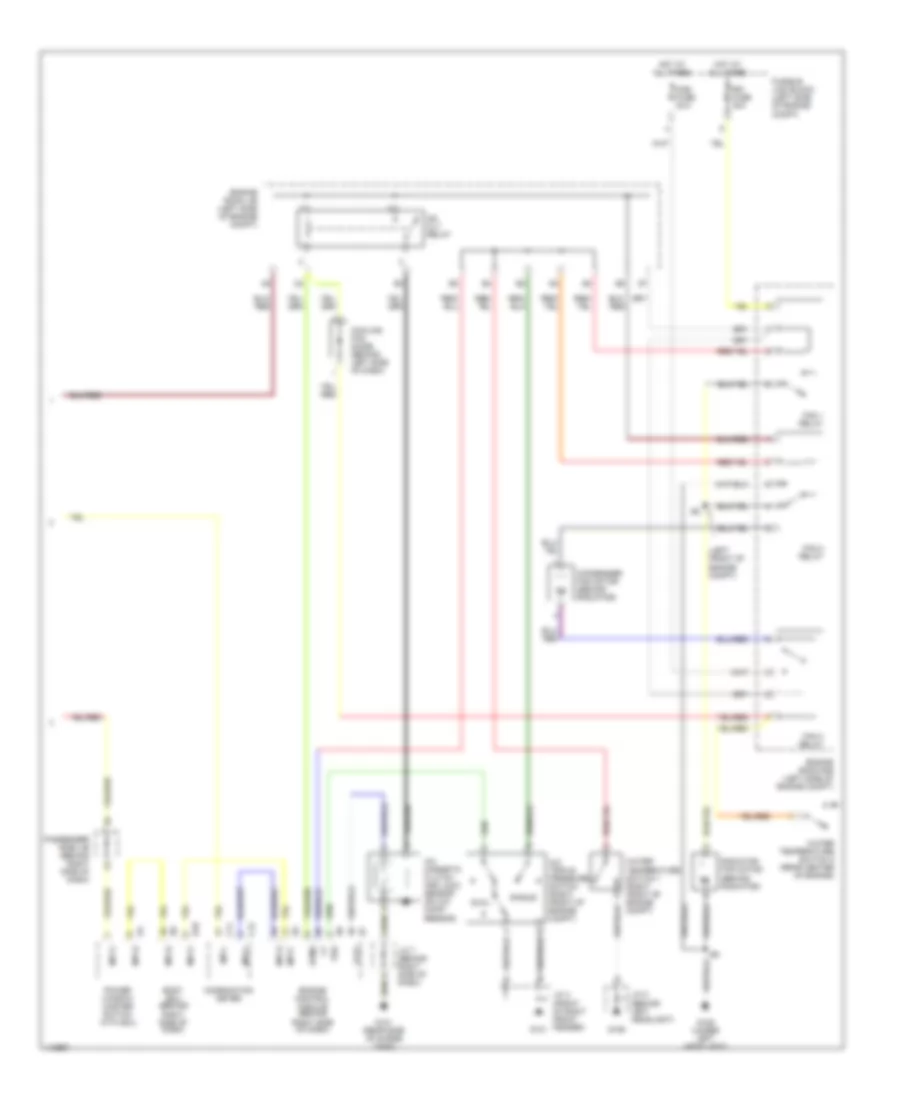
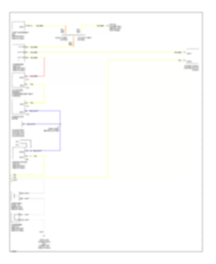
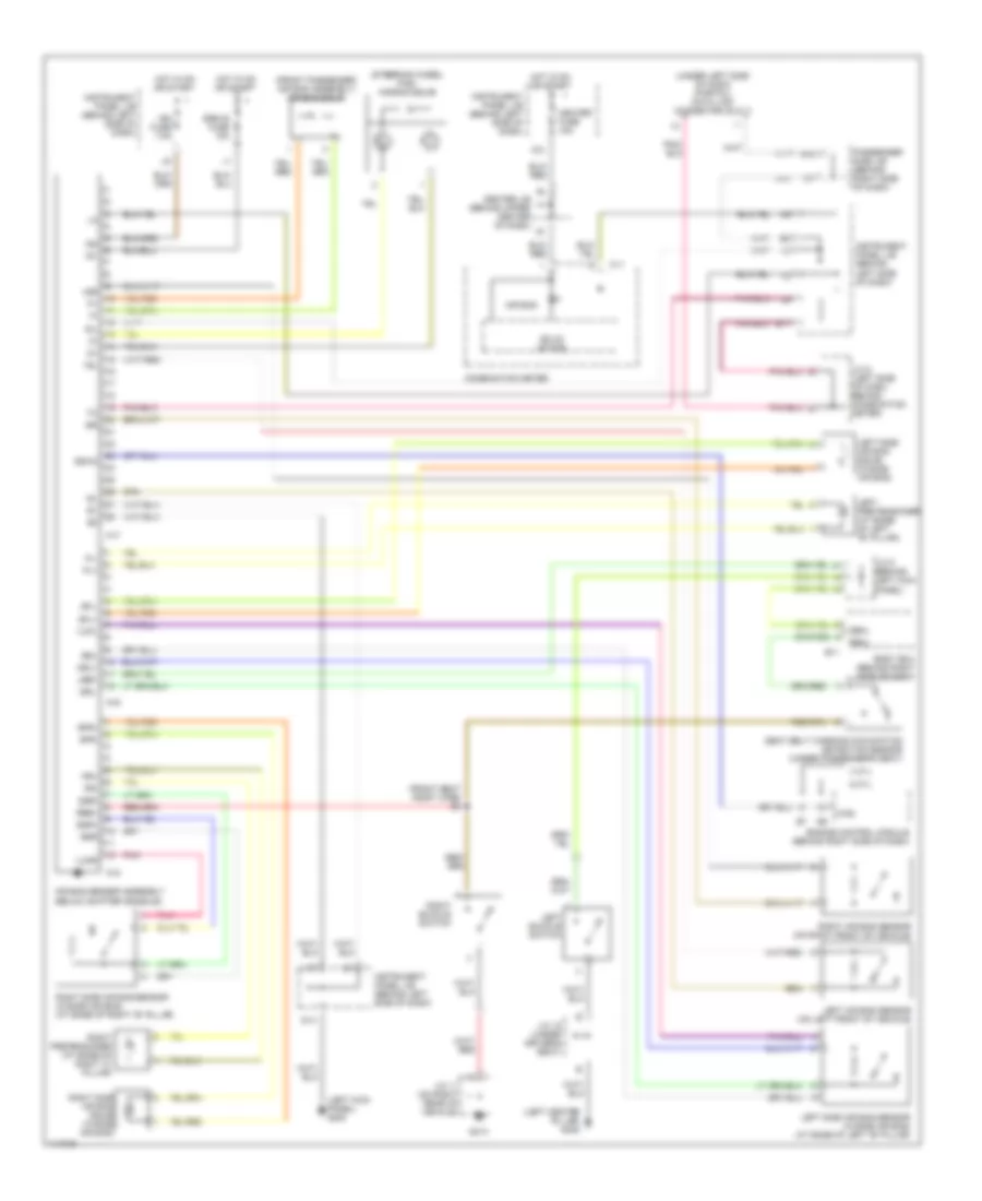
2.4L, Manual A/C Wiring Diagram (1 of 2) for Toyota Highlander Limited 2001
 https://portal-diagnostov.com/license.html
Automotive Electricians Portal FZCO
Automotive Electricians Portal FZCO
https://portal-diagnostov.com/license.html
https://portal-diagnostov.com/license.html
Automotive Electricians Portal FZCO
Automotive Electricians Portal FZCO
List of elements for 2.4L, Manual A/C Wiring Diagram (1 of 2) for Toyota Highlander Limited 2001:
- (behind center of dash)
- (behind center of dash) i5
- A/c control assembly (behind center of dash)
- A10
- A11
- A12
- A13
- A14
- A15
- A16
- A17
- A18
- A19
- A20
- A21
- A22
- Acc
- Aif
- Air
- Air inlet control servo motor (behind upper center of dash)
- Air mix control servo motor (behind center of dash)
- Air vent control servo motor (behind left center of dash)
- Amc
- Amh
- Aod
- Aof
- B10
- B11
- B12
- B13
- B14
- B15
- B16
- Blower control switch
- Blower motor (behind right side of dash)
- Blower resistor (behind right side of dash)
- Center j/b (behind upper center of dash)
- Clk
- Control panel switch
- Dpd
- Ecu-b fuse 7.5a
- Engine room j/b (left side of engine compt)
- Evaporator temperature sensor (behind right side of dash)
- F13
- Fresh
- Fusible link block (left side of engine compt)
- G10
- G200 (left kick panel)
- G203 (upper right kick panel)
- G206 (center of dash, on right dash brace)
- Gnd
- Haz
- Heater fuse 10a
- Heater fuse 50a
- Heater relay (behind left side of dash, right of instrument panel j/b)
- Hot at all times
- Hot in on or acc
- Hot in on or start
- I10
- I11
- Ig+
- Ill+
- Ill-
- Instrument panel j/b (behind left side of dash)
- Interior lights system
- J/c 5 (left side of dash, behind cluster)
- J10
- K13
- Mpx+
- Mpx-
- Mr/f
- Off
- Passenger side j/b (behind right side of dash)
- Pnk
- Radio 2 fuse 7.5a
- Rec
- Red
- S5-1
- Sg-1
- Stx
- Swd
- Test
- Tpo
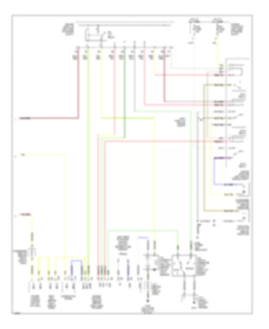
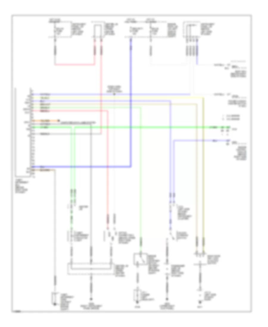
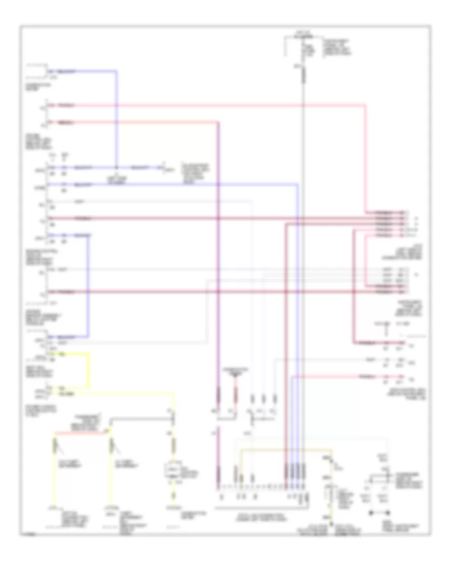
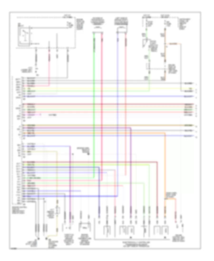
2.4L, Manual A/C Wiring Diagram (2 of 2) for Toyota Highlander Limited 2001
List of elements for 2.4L, Manual A/C Wiring Diagram (2 of 2) for Toyota Highlander Limited 2001:
- (left front of engine compt)
- (left rear of engine) engine coolant temperature sensor
- A/c magnetic clutch and lock sensor (on a/c comp- ressor)
- A/c triple pressure switch (right front of engine compt)
- Acmg
- B10
- Body ecu (behind right side of dash)
- C11
- C12
- Cds fuse 30a
- Combination meter
- Condenser fan motor (behind radiator)
- Dual
- Engine control module (behind right side of dash)
- Engine room j/b (left side of engine compt)
- Engine room r/b (left side of engine compt)
- Fan
- Fan 1 relay
- Fan 2 relay
- Fan 3 relay
- Fusible link block (left side of engine compt)
- G101
- G106 (under left headlight)
- G132 (on intake side of cyl block)
- Hot at all times
- J/c 4 (front of right front fender)
- J/c 7 (behind right side of dash)
- Lck1
- Mg clt relay
- Mpx+
- Mpx-
- Mpx1
- Mpx2
- Passenger side j/b (behind right side of dash)
- Power window master switch with ecu
- Pr2
- Pre
- Radiator fan motor (behind radiator)
- Rdi fuse 30a
- Single
- Thw
3.0L
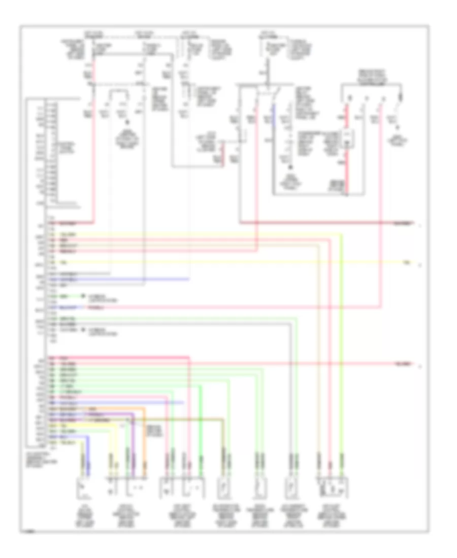
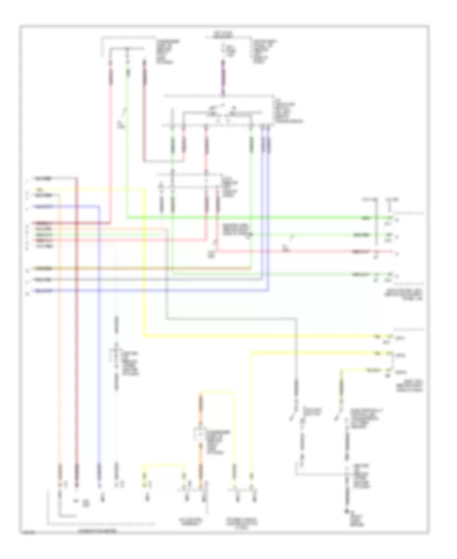
3.0L, Automatic A/C Wiring Diagram (1 of 2) for Toyota Highlander Limited 2001
List of elements for 3.0L, Automatic A/C Wiring Diagram (1 of 2) for Toyota Highlander Limited 2001:
- (behind center of dash)
- (behind center of dash) i9
- (behind right side of dash) blower motor controller
- A/c ambient temperature sensor (front center of grille)
- A/c control assembly (behind center of dash)
- A/c solar sensor (upper left side of dash)
- A10
- A11
- A12
- A13
- A14
- A15
- A16
- A17
- A18
- A19
- A20
- A21
- A22
- Acc
- Aif
- Air
- Air inlet control servo motor (behind upper center of dash)
- Air mix control servo motor (behind center of dash)
- Air vent control servo motor (behind left center of dash)
- Amc
- Amh
- Aod
- Aof
- B10
- B11
- B12
- B13
- B14
- B15
- B16
- Blower motor (behind right side of dash)
- Blw
- Center j/b (behind upper center of dash)
- Clk
- Control panel switch
- Dpd
- Ecu-b fuse 7.5a
- Engine room j/b (left side of engine compt)
- Evaporator temperature sensor (behind right side of dash)
- F13
- Fresh
- Fusible link block (left side of engine compt)
- G10
- G200 (left kick panel)
- G203 (upper right kick panel)
- G206 (center of dash, on right dash brace)
- Gnd
- Haz
- Heater fuse 10a
- Heater fuse 50a
- Heater relay (behind left side of dash, right of instrument panel j/b)
- Hot at all times
- Hot in on or acc
- Hot in on or start
- I11
- Ig+
- Ill+
- Ill-
- Instrument panel j/b (behind left side of dash)
- Interior lights system
- J/c 5 (left side of dash, behind cluster)
- K13
- Mpx+
- Mpx-
- Mr/f
- Passenger side j/b (behind right side of dash)
- Pnk
- Radio 2 fuse 7.5a
- Rec
- Red
- Room temperature sensor (behind center of dash)
- S5-1
- S5-3
- Sg-1
- Sg-3
- Sg-5
- Stx
- Swd
- Tam
- Tpo
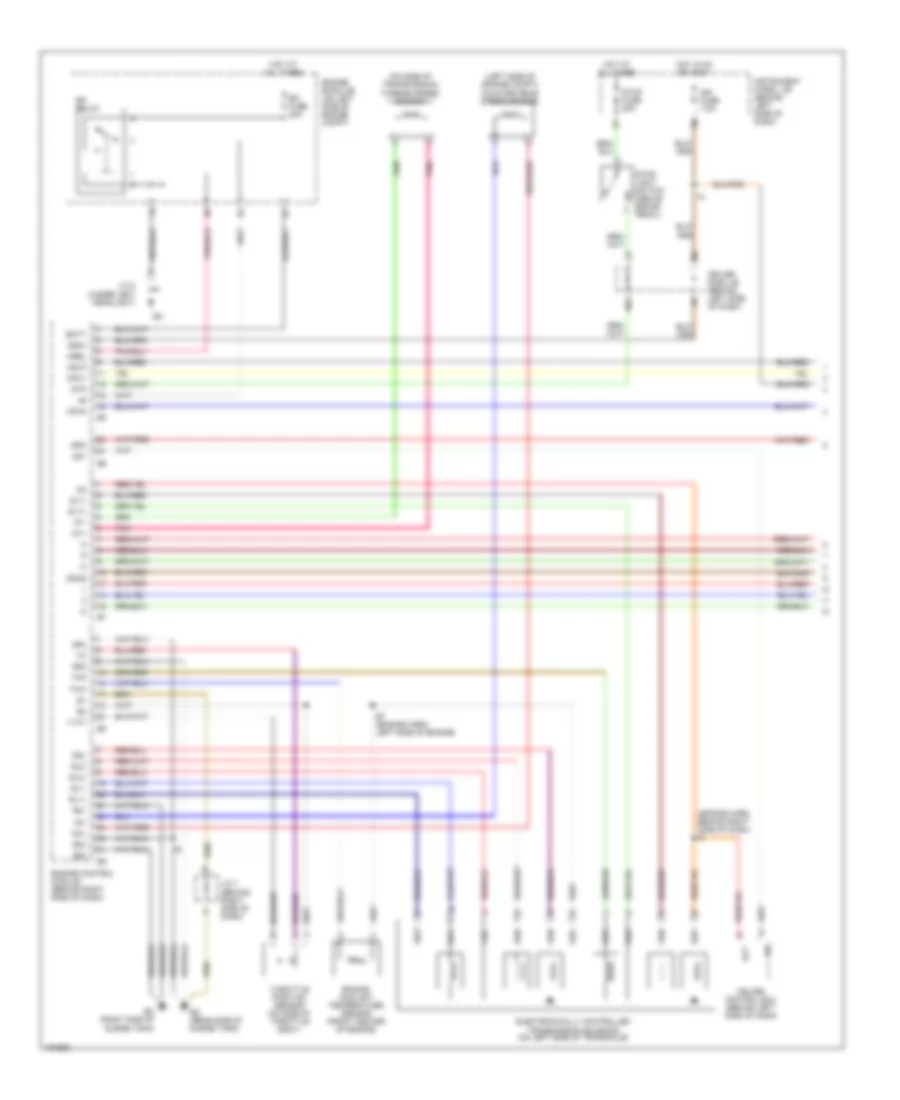
3.0L, Automatic A/C Wiring Diagram (2 of 2) for Toyota Highlander Limited 2001
List of elements for 3.0L, Automatic A/C Wiring Diagram (2 of 2) for Toyota Highlander Limited 2001:
- (left front of engine compt)
- A/c magnetic clutch and lock sensor (on a/c comp- ressor)
- A/c triple pressure switch (right front of engine compt)
- Acmg
- B10
- Body ecu (behind right side of dash)
- C11
- C12
- Cds fuse 30a
- Combination meter
- Condenser fan motor (behind radiator)
- Cooling fan diode (behind left side of dash)
- Dual
- Engine control module (behind right side of dash)
- Engine room j/b (left side of engine compt)
- Engine room r/b (left side of engine compt)
- Fan 1 relay
- Fan 2 relay
- Fan 3 relay
- Fusible link block (left side of engine compt)
- G101
- G106
- G106 (under left headlight)
- G121 (rear side of surge tank)
- Hot at all times
- J/c 2 (behind left headlight)
- J/c 4 (front of right front fender)
- J/c 7 (behind right side of dash)
- Lck1
- Mg clt relay
- Mpx+
- Mpx-
- Mpx1
- Mpx2
- Passenger side j/b (behind right side of dash)
- Power window master switch with ecu
- Pre
- Radiator fan motor (behind radiator)
- Rdi fuse 30a
- Single
- Water temperature switch 1 (right front of engine compt)
- Water temperature switch 2 (rear center of engine)
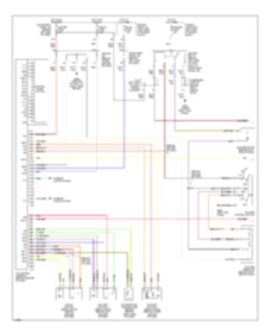
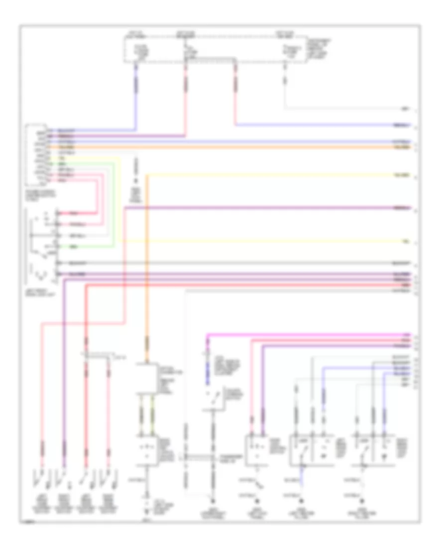
3.0L, Manual A/C Wiring Diagram (1 of 2) for Toyota Highlander Limited 2001
List of elements for 3.0L, Manual A/C Wiring Diagram (1 of 2) for Toyota Highlander Limited 2001:
- (behind center of dash)
- (behind center of dash) i5
- A/c control assembly (behind center of dash)
- A10
- A11
- A12
- A13
- A14
- A15
- A16
- A17
- A18
- A19
- A20
- A21
- A22
- Acc
- Aif
- Air
- Air inlet control servo motor (behind upper center of dash)
- Air mix control servo motor (behind center of dash)
- Air vent control servo motor (behind left center of dash)
- Amc
- Amh
- Aod
- Aof
- B10
- B11
- B12
- B13
- B14
- B15
- B16
- Blower control switch
- Blower motor (behind right side of dash)
- Blower resistor (behind right side of dash)
- Center j/b (behind upper center of dash)
- Clk
- Control panel switch
- Dpd
- Ecu-b fuse 7.5a
- Engine room j/b (left side of engine compt)
- Evaporator temperature sensor (behind right side of dash)
- F13
- Fresh
- Fusible link block (left side of engine compt)
- G10
- G200 (left kick panel)
- G203 (upper right kick panel)
- G206 (center of dash, on right dash brace)
- Gnd
- Haz
- Heater fuse 10a
- Heater fuse 50a
- Heater relay (behind left side of dash, right of instrument panel j/b)
- Hot at all times
- Hot in on or acc
- Hot in on or start
- I10
- I11
- Ig+
- Ill+
- Ill-
- Instrument panel j/b (behind left side of dash)
- Interior lights system
- J/c 5 (left side of dash, behind cluster)
- J10
- K13
- Mpx+
- Mpx-
- Mr/f
- Off
- Passenger side j/b (behind right side of dash)
- Pnk
- Radio 2 fuse 7.5a
- Rec
- Red
- S5-1
- Sg-1
- Stx
- Swd
- Test
- Tpo
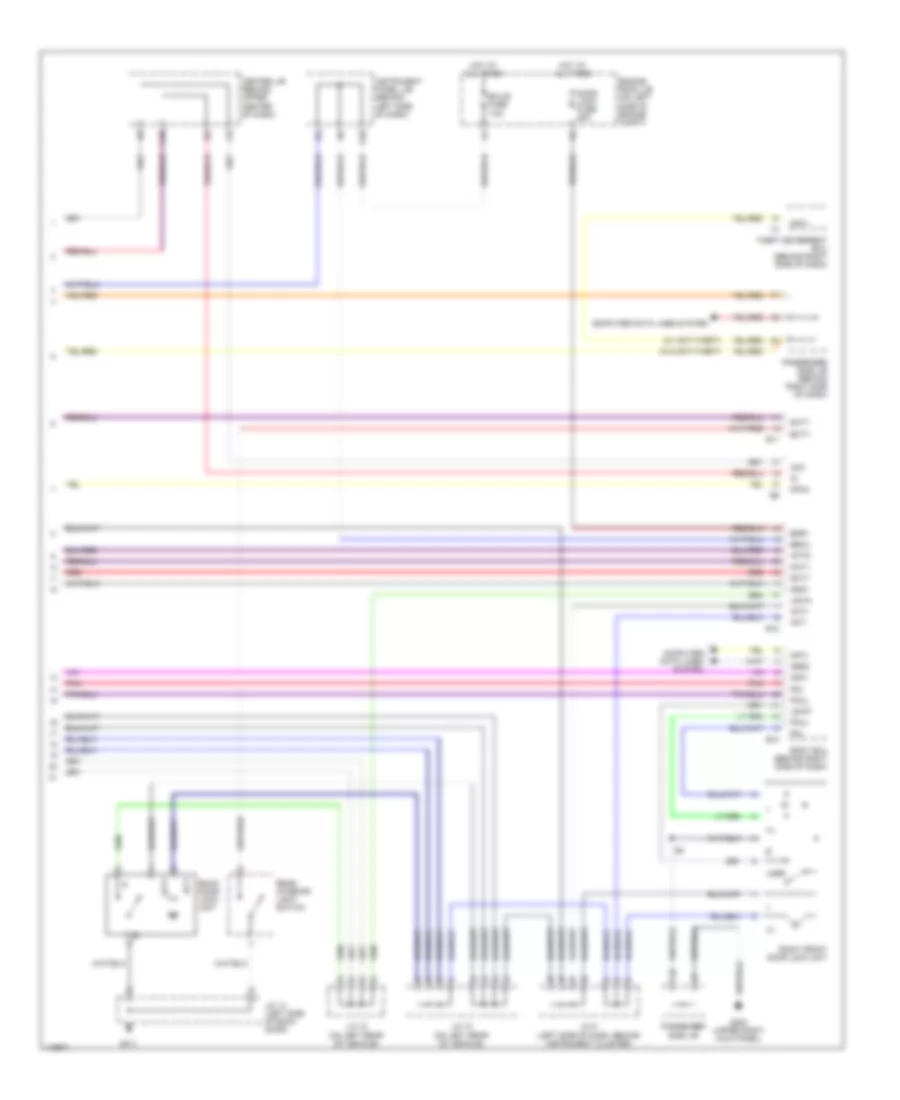
3.0L, Manual A/C Wiring Diagram (2 of 2) for Toyota Highlander Limited 2001
List of elements for 3.0L, Manual A/C Wiring Diagram (2 of 2) for Toyota Highlander Limited 2001:
- (left front of engine compt)
- A/c magnetic clutch and lock sensor (on a/c comp- ressor)
- A/c triple pressure switch (right front of engine compt)
- Acmg
- B10
- Body ecu (behind right side of dash)
- C11
- C12
- Cds fuse 30a
- Combination meter
- Condenser fan motor (behind radiator)
- Cooling fan diode (behind left side of dash)
- Dual
- Engine control module (behind right side of dash)
- Engine room j/b (left side of engine compt)
- Engine room r/b (left side of engine compt)
- Fan 1 relay
- Fan 2 relay
- Fan 3 relay
- Fusible link block (left side of engine compt)
- G101
- G106
- G106 (under left headlight)
- G121 (rear side of surge tank)
- Hot at all times
- J/c 2 (behind left headlight)
- J/c 4 (front of right front fender)
- J/c 7 (behind right side of dash)
- Lck1
- Mg clt relay
- Mpx+
- Mpx-
- Mpx1
- Mpx2
- Passenger side j/b (behind right side of dash)
- Power window master switch with ecu
- Pre
- Radiator fan motor (behind radiator)
- Rdi fuse 30a
- Single
- Water temperature switch 1 (right front of engine compt)
- Water temperature switch 2 (rear center of engine)
ANTI-LOCK BRAKES
Anti-lock Brake Wiring Diagrams, with VSC (1 of 3) for Toyota Highlander Limited 2001
List of elements for Anti-lock Brake Wiring Diagrams, with VSC (1 of 3) for Toyota Highlander Limited 2001:
- +bi
- +bo
- A12
- Abs
- Abs 1 fuse 40a
- Abs 2 fuse 40a
- Abs r/b (on left rear of engine compt)
- Abs sol relay
- Brake
- Brake warning switch (on master cylinder assembly)
- Brl
- C11
- C12
- Combination meter
- Data link connector 3 (under left side of dash)
- Eng+
- Engine room r/b 1 (on left side of engine compt)
- Fl+
- Fl-
- Fr+
- Fr-
- Fusible link block (on left side of engine compt)
- G101
- Gnd1
- Gnd2
- Hot at all times
- Hot in run and start
- Ig1
- Ign fuse 7.5a
- Ind
- Instrument panel j/b (behind left side of dash)
- J/c 4 (right side of engine compartment)
- J/c 6 (left side of dash behind instrument cluster)
- Lbl
- Left front abs speed sensor
- Left rear abs speed sensor
- Mr2
- Parking brake switch (on base of park brake lever)
- Passengers side j/b (behind right side of dash)
- Passengers side j/b (behind right side of dash)
- Pkb
- R1+
- R2+
- Right front abs speed sensor
- Right rear abs speed sensor
- Rl+
- Rl-
- Rr+
- Rr-
- S11
- S12
- Sflh
- Sflr
- Sil
- Skid control ecu (above instrument panel j/b)
- Skid control relay
- Slip
- Sp1
- Src1
- Src2
- Srm1
- Srm2
- Srrh
- Srrr
- Stp
- Trac off
- Trc+
- Trc-
- Vsc
- Vscw
Anti-lock Brake Wiring Diagrams, with VSC (2 of 3) for Toyota Highlander Limited 2001
List of elements for Anti-lock Brake Wiring Diagrams, with VSC (2 of 3) for Toyota Highlander Limited 2001:
- (under left headlight)
- 2.4l
- 3.0l
- A11
- Abs 3 fuse 7.5a engine room r/b (left side of engine compartment)
- Brake actuator (left rear of engine compartment)
- E5 e6
- Ecu-b fuse 7.5a
- Eng+
- Engine control module (behind right side of dash)
- Engine room j/b (left side of engine compartment)
- G106
- Hot at all times
- Instrument panel j/b (behind left side of dash)
- Master cylinder pressure sensor
- Neo
- Passenger side j/b (behind right side of dash)
- Red
- Shield
- Stop fuse 20a
- Stoplight switch (above brake pedal)
- Trc+
- Trc-
Anti-lock Brake Wiring Diagrams, with VSC (3 of 3) for Toyota Highlander Limited 2001
List of elements for Anti-lock Brake Wiring Diagrams, with VSC (3 of 3) for Toyota Highlander Limited 2001:
- 1mz-fe
- 2az-fe
- 2wd
- A/t indicator switch (left side of transmission)
- Ast
- Bat
- Brake pedal load sensing switch (above brake pedal)
- C11
- Center j/b (behind upper center of dash)
- Cruise control system
- Csw
- D/g
- D10
- Deceleration sensor (at base of shifter lever
- Ecu-ig fuse 15a
- Ess
- Fss
- Fsw+
- Fsw-
- G106
- G203 (upper right kick panel)
- G206 (right instriment panel brace)
- Ggnd
- Gl1
- Gl2
- Gnd3
- Gnd4
- Gss
- Gyaw
- Hot in run and start
- Ig1 fuse 7.5a
- Instrument panel j/b (behind left side of dash)
- J/c 2 (behind left headlamp)
- J/c 6 (left side of dash behind instrument cluster)
- J/c 8 (behind right side of dash)
- Neo
- Passenger side j/b (behind right side of dash)
- Pmc
- Red
- S10
- Sfrh
- Sfrr
- Shield
- Skid control ecu (above instrument panel j/b)
- Sm1+
- Sm1-
- Sm2+
- Sm2-
- Srlh
- Srlr
- Ss1+
- Ss1-
- Trac off switch (left side of dash)
- Trig
- Vcm
- Vgs
- Vsc steering sensor (in steering column)
- Vsc warning buzzer (above i/p junction block)
- Vys
- Yaw rate sensor (on rear of vehicle)
- Yaw2
- Yss
Anti-lock Brake Wiring Diagrams, without VSC (1 of 2) for Toyota Highlander Limited 2001
List of elements for Anti-lock Brake Wiring Diagrams, without VSC (1 of 2) for Toyota Highlander Limited 2001:
- A12
- Abs 1 fuse 25a
- Abs 2 fuse 40a
- Abs mtr relay
- Abs sol relay
- Ast
- Automatic transmission system
- Brl
- D/g
- D10
- Data link connector 3 (under left side of dash)
- Ecu-ig fuse 15a
- Engine room r/b 1 (on left side of engine compt)
- Fusible link block (on left side of engine compt)
- G106
- Gnd3
- Gnd4
- Hot at all times
- Hot in run and start
- Ig1
- Instrument panel j/b (behind left side of dash)
- J/c 2 (under left headlight)
- J/c 6 (left side of dash behind instrument cluster)
- Left front abs speed sensor
- Left rear abs speed sensor
- Mrf
- Parking brake switch (on base of park brake lever)
- Passengers side j/b (behind right side of dash)
- Pkb
- Pnk
- Right front abs speed sensor
- Right rear abs speed sensor
- Rl+
- Rl-
- Rr+
- Rr-
- Sflh
- Sflr
- Sil
- Skid control ecu (above instrument panel j/b)
- Sm1+
- Sm1-
- Sm2+
- Sm2-
- Sp1
- Srrh
- Srrr
- Stp
Anti-lock Brake Wiring Diagrams, without VSC (2 of 2) for Toyota Highlander Limited 2001
List of elements for Anti-lock Brake Wiring Diagrams, without VSC (2 of 2) for Toyota Highlander Limited 2001:
- (under left headlight)
- A11
- Abs
- Abs 3 fuse 7.5a
- Brake
- Brake actuator (left rear of engine compartment)
- Brake warning switch (on master cylinder assembly)
- C11
- C12
- Combination meter
- Deceleration sensor (at base of shifter lever)
- Engine room r/b (left side of engine compartment)
- Fl+
- Fl-
- Fr+
- Fr-
- Fss
- G101
- G106
- Ggnd
- Gl1
- Gnd1
- Gnd2
- Gss
- Hot at all times
- Hot in run and start
- Ign fuse 7.5a
- Instrument panel j/b (behind left side of dash)
- J/c 4 (front of right front fender)
- Master cylinder pressure sensor
- Passenger side j/b (behind right side of dash)
- Pmc
- Pnk
- Red
- Sfrh
- Sfrr
- Shield
- Skid control ecu (above instrument panel j/b)
- Splh
- Srlr
- Srm1
- Srm2
- Stop fuse 15a
- Stoplight switch (above brake pedal)
- Vcm
- Vgs
ANTI-THEFT
Forced Entry Wiring Diagram for Toyota Highlander Limited 2001
List of elements for Forced Entry Wiring Diagram for Toyota Highlander Limited 2001:
- (dash harn, top right side of dash) i4
- +b1
- 2.4l engine
- 3.0l engine
- B12
- Back door key lock & unlock switch
- Becu
- Body ecu (behind right side of dash)
- Center j/b
- Center j/b (behind upper center of dash)
- Computer data lines system
- Cpub
- Dswh
- Ecu-b fuse 7.5a
- Ecu-ig fuse 15a
- Engine control module (behind right side of dash)
- Engine hood courtesy switch (on front center of engine compt)
- Engine room j/b (on left side of engine compt)
- F11
- F13
- G10
- G106
- G203 (upper right kick panel)
- G206 (right instrument panel brace)
- G411
- Gnd
- Hot at all times
- Hot in on or start
- Imld
- Ind
- Instrument panel j/b (behind left side of dash)
- Iout
- J/c 1 (under left headlight)
- J/c 14 (left side of back door)
- J/c 6 (left side of dash, behind instrument cluster)
- J11
- K11
- Ksw
- Mpx1
- Option connector 2 (behind upper right side of dash)
- Passenger side j/b (behind right side of dash)
- Power window master switch w/ ecu
- Security fuse 15a
- Sh-
- Theft deterrent ecu (behind right side of dash)
- Theft deterrent horn (on right side of engine compt)
- Theft deterrent indicator light
- Ul2
- Unlock warning switch
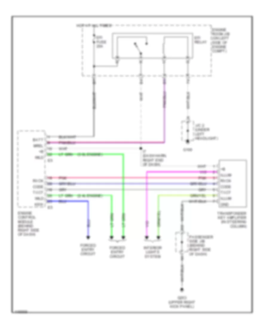
Immobilizer Wiring Diagram for Toyota Highlander Limited 2001
List of elements for Immobilizer Wiring Diagram for Toyota Highlander Limited 2001:
- (2.4l engine)
- (3.0l engine)
- Batt
- Code
- Efi fuse 20a
- Efi relay
- Engine control module (behind right side of dash)
- Engine room j/b (on left side of engine compt)
- Forced entry circuit
- G106
- G203 (upper right kick panel)
- Gnd
- Hot at all times
- I7 (dash harn, right end of dash)
- Illum
- Imld
- Interior lights system
- J/c 2 (under left headlight)
- Ksw
- Mrel
- Passenger side j/b (behind right side of dash)
- Pnk
- Rxck
- Transponder key amplifier (in steering column)
- Txct
BODY COMPUTER
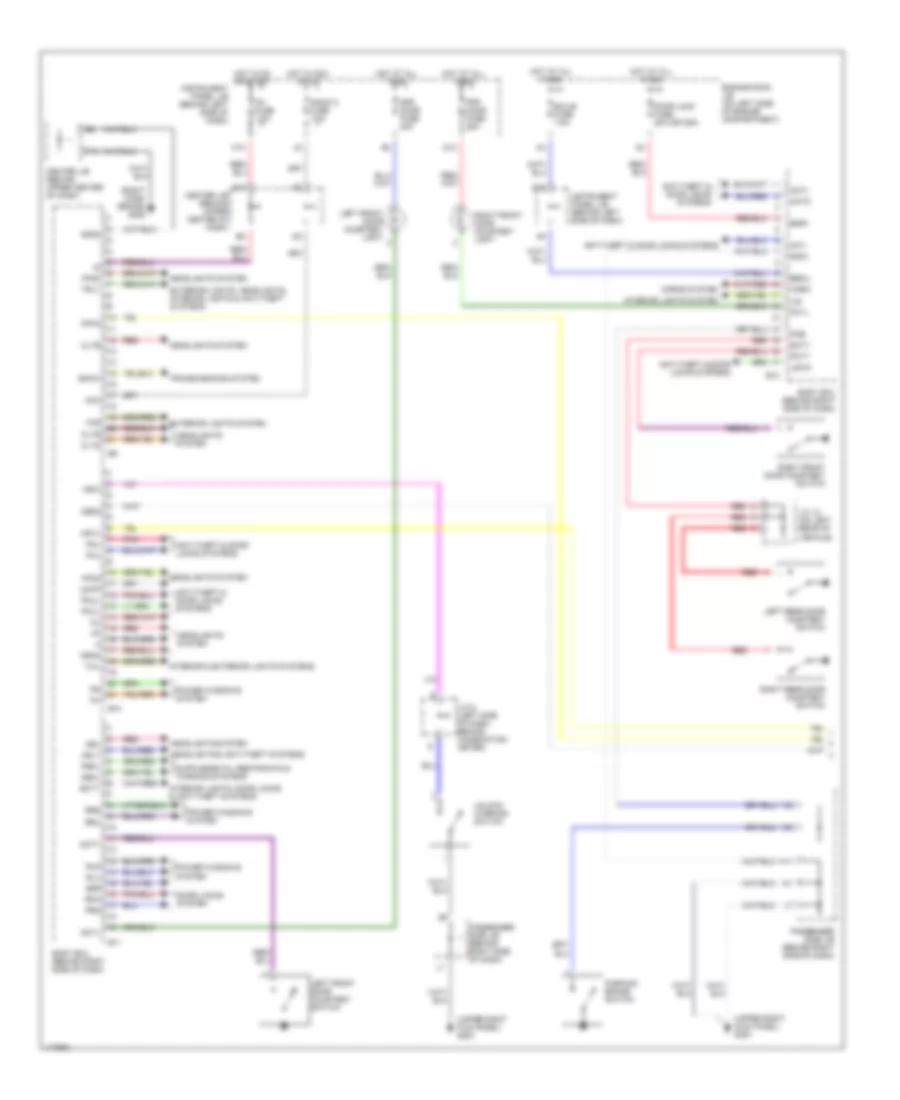
Body Computer Wiring Diagrams (1 of 2) for Toyota Highlander Limited 2001
List of elements for Body Computer Wiring Diagrams (1 of 2) for Toyota Highlander Limited 2001:
- (right dash brace) g206
- (upper right kick panel) g203
- A10
- Acc
- Act+
- Act-
- Actd
- Anti-theft & door locks systems
- B10
- B11
- B12
- Bcty
- Bdr1
- Becu
- Body ecu (behind right side of dash)
- Bzr
- Center j/b (behind upper center of dash)
- Cltb
- Clte
- Clts
- D12
- Dbkl
- Dcty
- Dcyl
- Dfr door fuse 20a
- Door lock fuse 20a (or 25a)
- Door locks system
- Drl
- Ecu-b fuse 7.5a
- Engine room j/b (on left side of engine compartment)
- Exterior lights system
- Exterior lights, headlights, interior lights & anti-theft systems
- F13
- Ffgo
- Ffog
- G10
- Gnd1
- Gnd2
- H11
- Haz
- Head
- Headlights & anti-theft systems
- Headlights system
- Horn
- Horns system
- Hot at all times
- Hot in acc or on
- Hot in on or start
- Hrly
- Ig1 fuse 7.5a
- Ile
- Instrument panel j/b (behind left side of dash)
- Interior & exterior lights systems
- Interior lights system
- Interior lights, door locks & anti-theft systems
- J/c 12 (on left rear of vehicle)
- J/c 6 (left side of dash, behind combination meter)
- K10
- Ksw
- Left front door courtesy light
- Left front door courtesy switch
- Left rear door courtesy switch
- Lswa
- Lswp
- Mpx1
- Mpx2
- Obd2
- Parking brake switch
- Passenger side j/b (behind right side of dash)
- Pbkl
- Pcty
- Pcyl
- Pfr door fuse 25a
- Pkb
- Pkl
- Pkul
- Pml
- Pmul
- Pnk
- Power windows system
- Prg
- Radio 2 fuse 7.5a
- Rcty
- Rda
- Red
- Right front door courtesy light
- Right front door courtesy switch
- Right rear door courtesy switch
- Rld
- Rlu
- Rrd
- Rru
- Snow
- Tail
- Transmissions system
- Trly
- Unlock warning switch
Body Computer Wiring Diagrams (2 of 2) for Toyota Highlander Limited 2001
List of elements for Body Computer Wiring Diagrams (2 of 2) for Toyota Highlander Limited 2001:
- 2.4l
- 3.0l
- 7 or 10
- A/c control assembly (passenger seat belt warning)
- A10
- A11
- A12
- C11
- C12
- Combination meter
- Data link connector 3 (dlc) (under left side of dash)
- E12
- Engine control module (behind right side of dash)
- I3 (dash harn, behind cluster)
- Instrument panel j/b (behind left side of dash)
- Mpx+
- Mpx-
- Mpx1
- Mpx2
- Option connector 1 (behind left kick panel)
- Passenger side j/b (behind right side of dash)
- Power window master switch (w/ecu)
- Sliding roof control ecu (on front of sliding roof)
- Theft deterrent ecu (behind right side of dash)
- W/anti-theft system
- W/o anti-theft system
COMPUTER DATA LINES
Computer Data Lines for Toyota Highlander Limited 2001
List of elements for Computer Data Lines for Toyota Highlander Limited 2001:
- (2.4l) g132 (on intake side of cyl block)
- 2.4l
- 3.0l
- A/c control switch
- A10
- A11
- A12
- A17
- Air bag sensor assembly (below shifter console)
- B10
- Bat
- Body ecu (behind right side of dash)
- C/c
- C11
- C12
- Combination meter
- Cruise control ecu (behind left side of dash)
- D/g
- Data link connector 3 (under left side of dash)
- E12
- Engine control module (behind right side of dash)
- G121 (3.0l) (rear side of surge tank)
- G206 (right instrument panel brace)
- Hot at all times
- I3 (left side of dash)
- I8 (3.0l)
- Instrument panel j/b (behind left side of dash)
- J/c 6 (left side of dash, behind combination meter)
- J/c 7 (behind right side of dash)
- Mpx+
- Mpx-
- Mpx1
- Mpx2
- Obd fuse 7.5a
- Option connector 1 (behind left kick panel)
- Passenger side j/b (behind right side of dash)
- Passenger side j/b (behind right side of dash)
- Power window master switch w/ ecu
- S10
- S11
- Sil
- Skid control ecu (above instrument panel j/b)
- Sliding roof control ecu (on front of sliding roof)
- Theft deterrent ecu (behind right side of dash)
- W/ theft deterrent
- W/ vsc
- W/o theft deterrent
- W/o vsc
- Wfse
COOLING FAN
2.4L
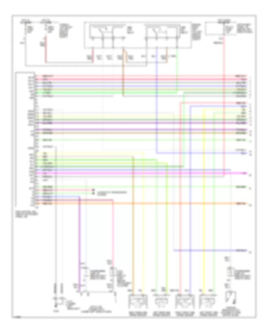
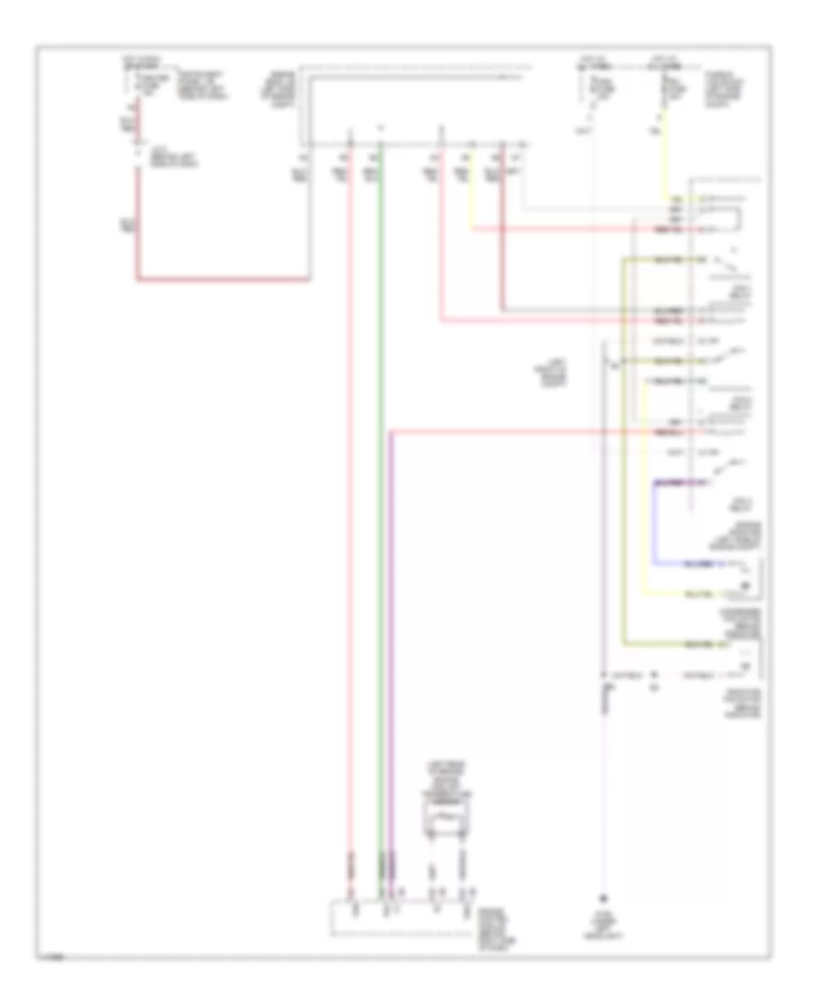
2.4L, Cooling Fan Wiring Diagram for Toyota Highlander Limited 2001
List of elements for 2.4L, Cooling Fan Wiring Diagram for Toyota Highlander Limited 2001:
- (left front of engine compt)
- (left rear of engine) engine coolant temperature sensor
- Cds fuse 30a
- Condenser fan motor (behind radiator)
- Engine control module (behind right side of dash)
- Engine room j/b (left side of engine compt)
- Engine room r/b (left side of engine compt)
- Fan
- Fan 1 relay
- Fan 2 relay
- Fan 3 relay
- Fusible link block (left side of engine compt)
- G106 (under left headlight)
- Heater fuse 15a
- Hot at all times
- Hot in run or start
- Instrument panel j/b (behind left side of dash)
- J/c 5 (behind left side of dash)
- Pr2
- Radiator fan motor (behind radiator)
- Rdi fuse 30a
- Thw
3.0L
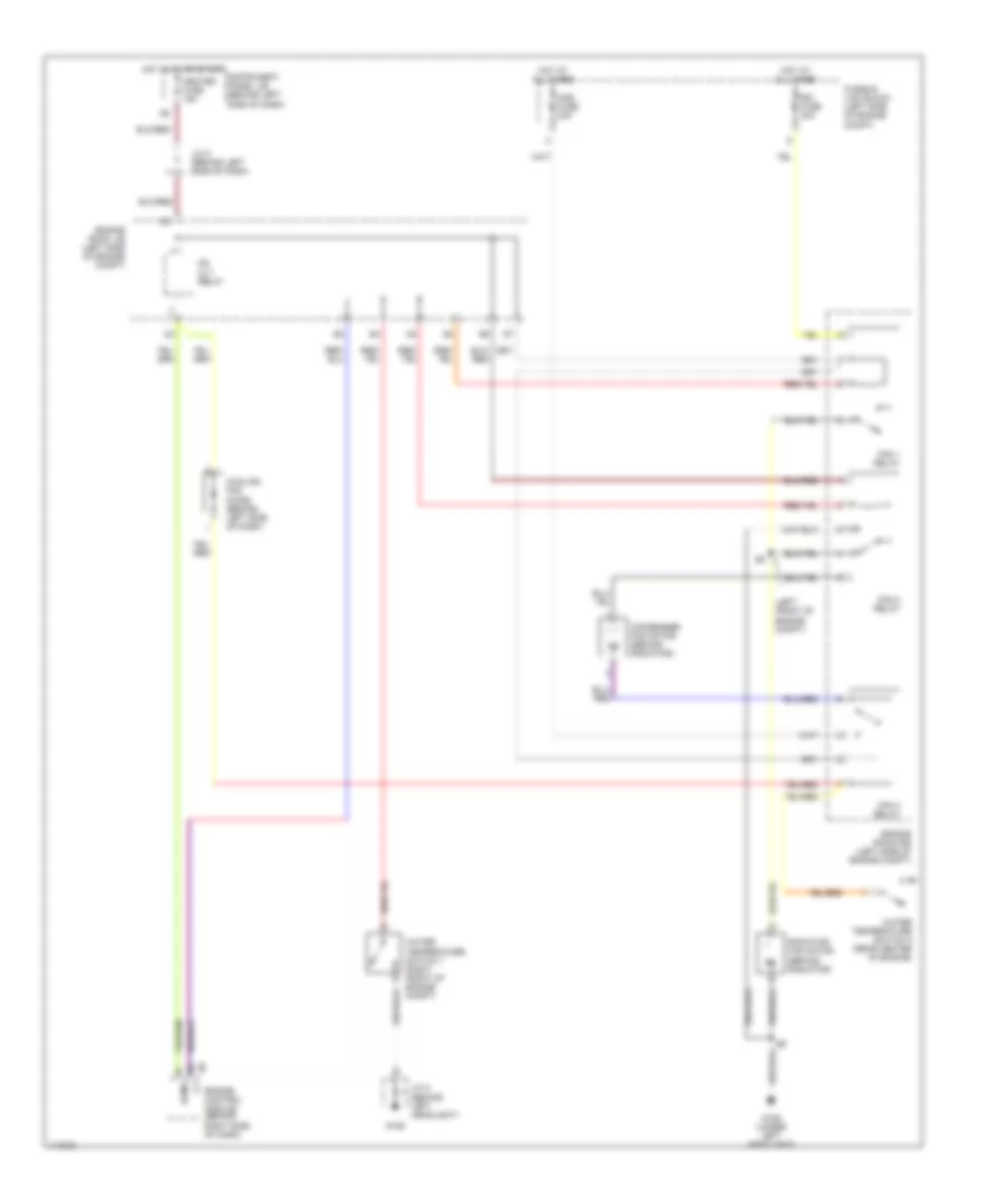
3.0L, Cooling Fan Wiring Diagram for Toyota Highlander Limited 2001
List of elements for 3.0L, Cooling Fan Wiring Diagram for Toyota Highlander Limited 2001:
- (left front of engine compt)
- Acmg
- Cds fuse 30a
- Condenser fan motor (behind radiator)
- Cooling fan diode (behind left side of dash)
- Engine control module (behind right side of dash)
- Engine room j/b (left side of engine compt)
- Engine room r/b (left side of engine compt)
- Fan 1 relay
- Fan 2 relay
- Fan 3 relay
- Fusible link block (left side of engine compt)
- G106
- G106 (under left headlight)
- Heater fuse 15a
- Hot at all times
- Hot in on or start
- Instrument panel j/b (behind left side of dash)
- J/c 2 (behind left headlight)
- J/c 5 (behind left side of dash)
- Mg clt relay
- Radiator fan motor (behind radiator)
- Rdi fuse 30a
- Water temperature switch 1 (right front of engine compt)
- Water temperature switch 2 (rear center of engine)
CRUISE CONTROL
Cruise Control Wiring Diagram for Toyota Highlander Limited 2001
List of elements for Cruise Control Wiring Diagram for Toyota Highlander Limited 2001:
- (w/ traction control)
- (w/o traction control)
- 12 (or 1)
- 2.4l engine
- 3.0l engine
- C/c
- C11
- C12
- C15
- Cancel
- Ccs
- Center j/b (behind upper center of dash)
- Combination meter
- Cruise
- Cruise control actuator (on right rear of engine compt)
- Cruise control ecu (behind left side of dash)
- Cruise control switch (spiral cable)
- Data link connector (dlc) 3 (under left side of dash)
- Ecc
- Ect
- Ecu-ig fuse 15a
- Engine control module (behind right side of dash)
- G13
- G203 (upper right kick panel)
- Gnd
- H10
- Hot at all times
- Hot in on or start
- Idl
- Idlo
- Ig1 fuse 7.5a
- Ign fuse 7.5a
- Instrument panel j/b (behind left side of dash)
- J/c 6 (left side of dash, behind instrument cluster)
- J/c 8 (behind right side of dash)
- Od1
- Park/neutral position switch (on left side of transmission)
- Passenger side j/b (behind right side of dash)
- Res/ acc
- S10
- Set/ coast
- Skid control ecu (above instrument panel j/b)
- Spd
- Stop fuse 20a
- Stoplight switch (above brake pedal)
- Stp
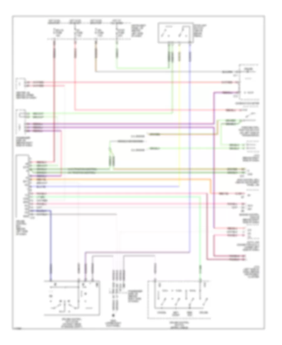
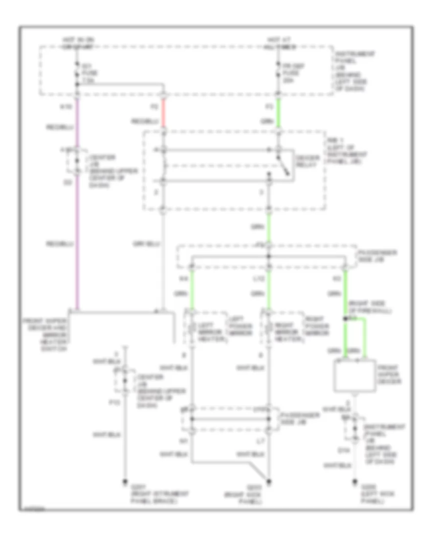
DEFOGGERS
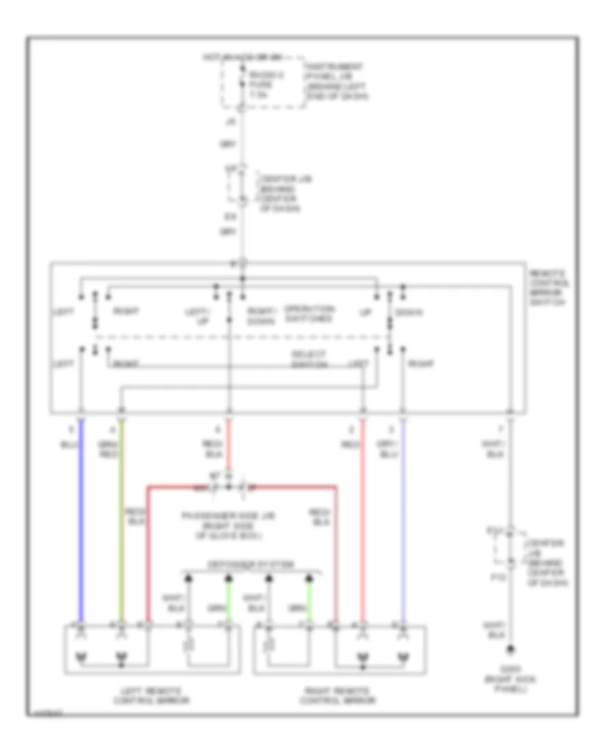
Mirror Heater & Front Deicer Wiring Diagram for Toyota Highlander Limited 2001
List of elements for Mirror Heater & Front Deicer Wiring Diagram for Toyota Highlander Limited 2001:
- (right side of firewall) e3
- A10
- Center j/b (behind upper center of dash)
- D14
- Deicer relay
- F13
- Fr def fuse 20a
- Front wiper deicer
- Front wiper deicer and mirror heater switch
- G200 (left kick panel)
- G201 (right istrument panel brace)
- G203 (right kick panel)
- Hot at all times
- Hot in on or start
- Ig1 fuse 7.5a
- Instrument panel j/b (behind left side of dash)
- K10
- L10
- L12
- Left mirror heater
- Left power mirror
- Passenger side j/b
- R/b 1 (left of instrument panel j/b)
- Right mirror heater
- Right power mirror
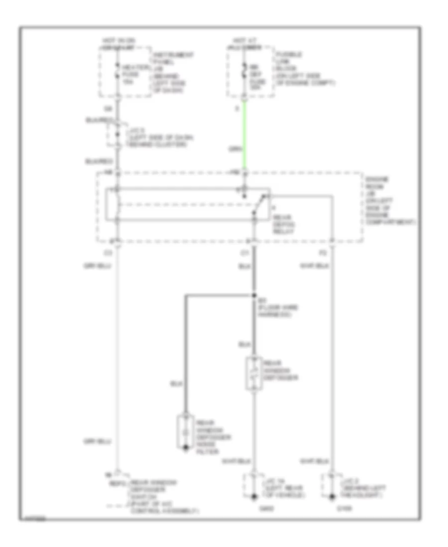
Rear Defogger Wiring Diagram for Toyota Highlander Limited 2001
List of elements for Rear Defogger Wiring Diagram for Toyota Highlander Limited 2001:
- B5 (floor wire harness)
- Engine room j/b (on left side of engine compartment)
- Fusible link block (on left side of engine compt)
- G106
- G402
- Heater fuse 15a
- Hot at all times
- Hot in on or start
- Instrument panel j/b (behind left side of dash)
- J/c 14 (left rear of vehicle)
- J/c 2 (behind left headlight)
- J/c 5 (left side of dash, behind cluster)
- Rdfg
- Rear defog relay
- Rear window defogger
- Rear window defogger noise filter
- Rear window defogger switch (part of a/c control assembly)
- Rr def fuse 30a
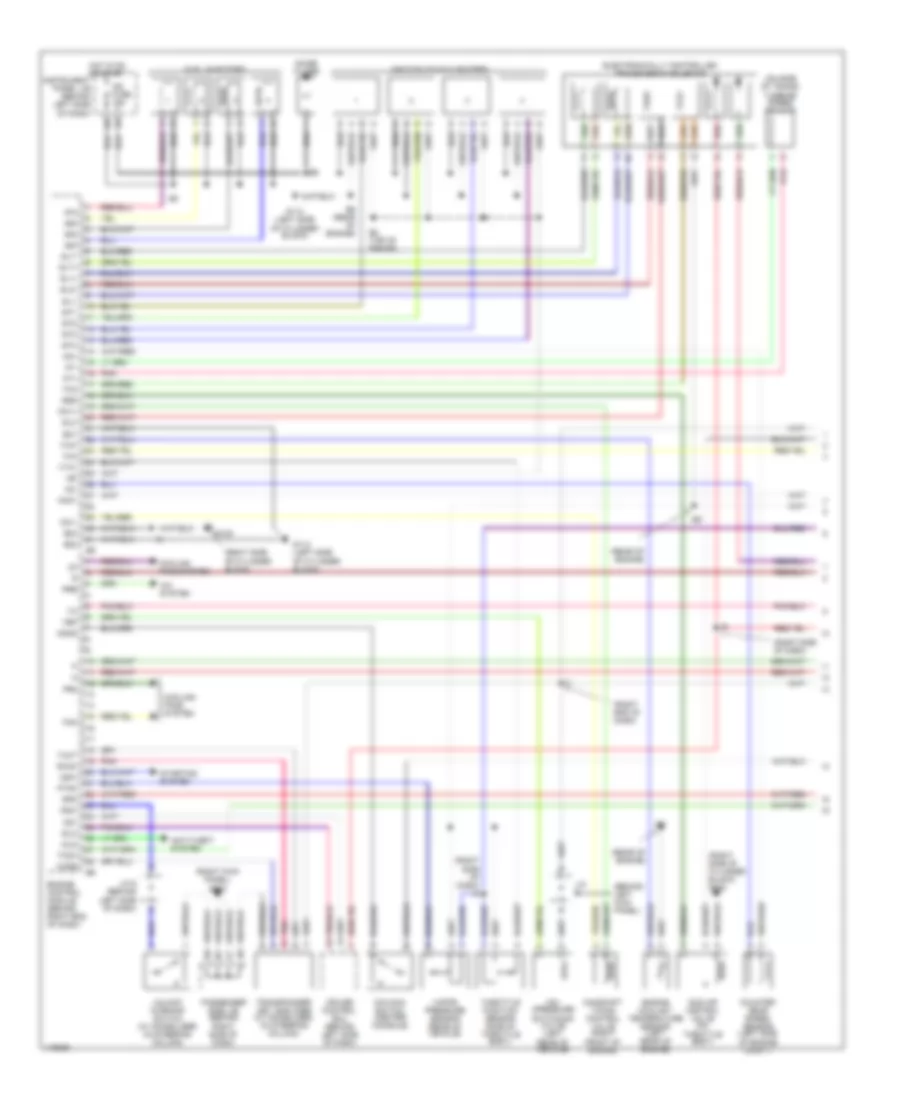
ENGINE PERFORMANCE
2.4L
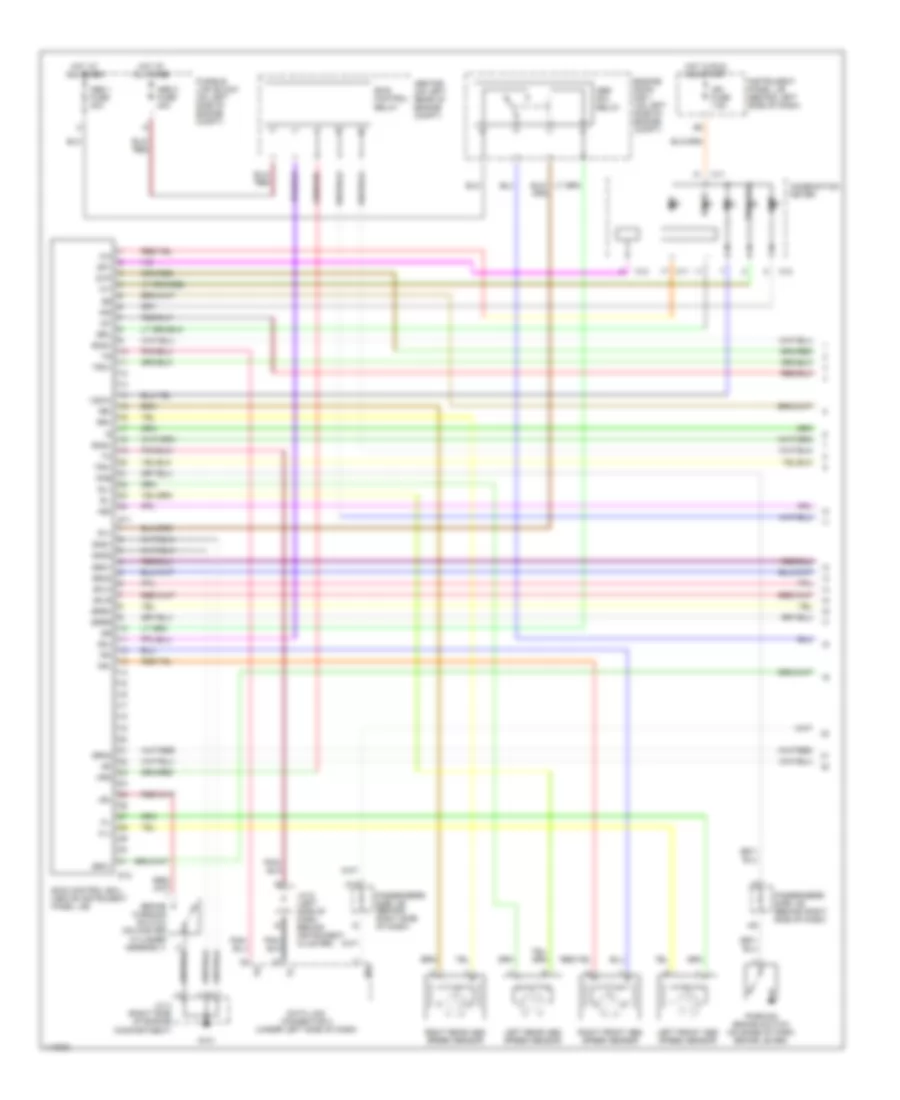
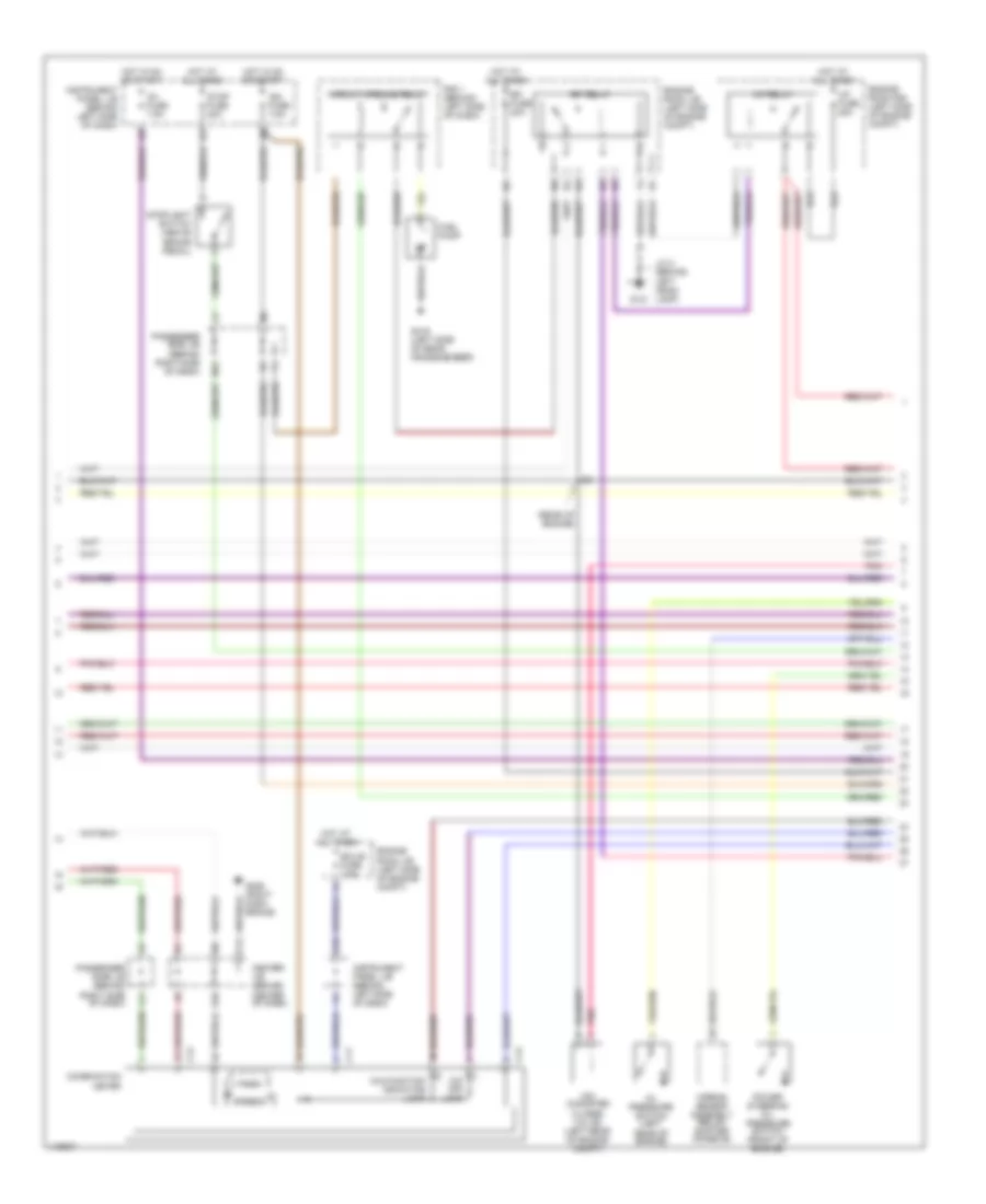
2.4L, Engine Performance Wiring Diagrams (1 of 3) for Toyota Highlander Limited 2001
List of elements for 2.4L, Engine Performance Wiring Diagrams (1 of 3) for Toyota Highlander Limited 2001:
- #10
- #20
- #30
- #40
- (behind left kick panel)
- (on side of trans) turbine speed sensor
- (rear of engine)
- (right end of dash)
- (right kick panel) g203
- (right side of cylinder block)
- (right side of cylinder block) g120
- (right side of dash)
- (right side of dash) i6
- A/c system
- Anti-theft system
- Camshaft timing control valve (right front of engine)
- Code
- Cooling fans system
- Cooling fans system
- Counter gear speed sensor (left side of engine compt)
- Cruise control ecu (behind left side of dash)
- E02
- E03
- E8 (top of engine)
- E9 (rear of engine)
- Electronically controlled transmission solenoid
- Engine control module (behind right end of dash)
- Engine coolant temperature sensor (left rear of engine)
- Eo1
- Fan
- Fuel injectors
- G112 (left side of cylinder block)
- G120
- Hot in on or start
- Idle air control valve (on throttle body)
- Idlo
- Ig2 fuse 15a
- Igf
- Ignition coils & igniters
- Igt1
- Igt2
- Igt3
- Igt4
- Imld
- Instrument panel j/b (behind left side of dash)
- J/c
- J/c 6 (behind left side of dash)
- Knk1
- Ksw
- Nc+
- Nc-
- Noise filter
- Nsw
- Nt+
- Nt-
- O/d main switch (center console)
- Ocv+
- Ocv-
- Od1
- Odms
- Passenger side j/b (behind right side of dash)
- Pnk
- Pr2
- Pre
- Ptnk
- Pvk
- Rear of vehicle)
- Red
- Rsd
- Rxck
- Sl1+
- Sl1-
- Sl2+
- Sl2-
- Slt+
- Slt-
- Spd
- Starting system
- Switching valve) (left
- Tach
- Tbp
- Tha
- Tho
- Throttle position sensor (side of throttle body)
- Thw
- Transponder key amplifier (w/ immobilizer) (in steering column)
- Txct
- Unlock warning switch (w/ immobilizer) (in steering column)
- Vapor pressure sensor (rear of vehicle)
- Vsv (pressure
- Vta1
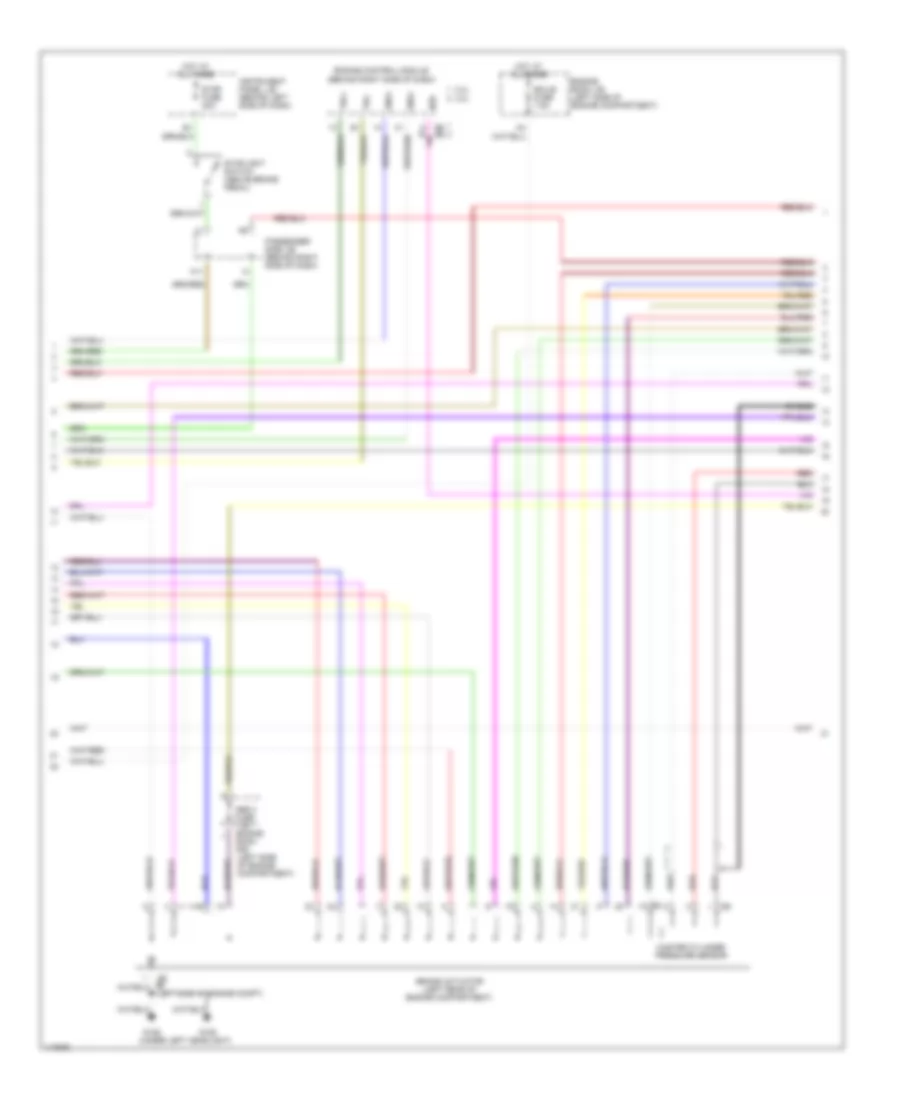
2.4L, Engine Performance Wiring Diagrams (2 of 3) for Toyota Highlander Limited 2001
List of elements for 2.4L, Engine Performance Wiring Diagrams (2 of 3) for Toyota Highlander Limited 2001:
- (rear of engine)
- A/f fuse 25a
- A/f relay
- Airbag sensor assembly (below shifter console)
- C11
- C12
- Center j/b (behind center of dash)
- Circuit opening relay
- Combination meter
- E10
- Ecu-b fuse 7.5a
- Efi fuse 20a
- Efi relay
- Engine room j/b (left side of engine compt)
- Engine room r/b (left side of engine compt)
- F13
- Fuel pump
- G10
- G121
- G206 (right dash brace)
- G416 (left side of rear crossmember)
- Hot at all times
- Hot in on or start
- Ig1 fuse 7.5a
- Ign fuse 7.5a
- Instrument panel j/b (behind left side of dash)
- J/c 2 (behind left head- lamp)
- L11
- M12
- Malfunction indicator lamp
- O/d off lamp
- Oil pressure switch (left rear of engine)
- Passenger side j/b (behind right side of dash)
- Pnk
- Power steering oil pressure switch (front of engine)
- R/b 1 (behind left side of dash)
- Speedo
- Stop fuse 20a
- Stoplight switch (above brake pedal)
- Tach
- Vsv (canister closed valve) (left rear of engine compt)
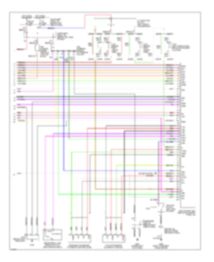
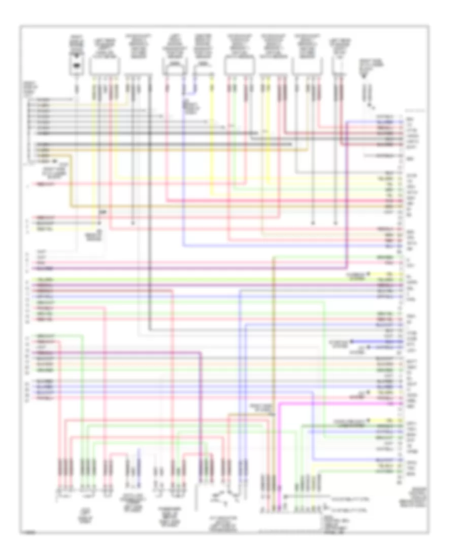
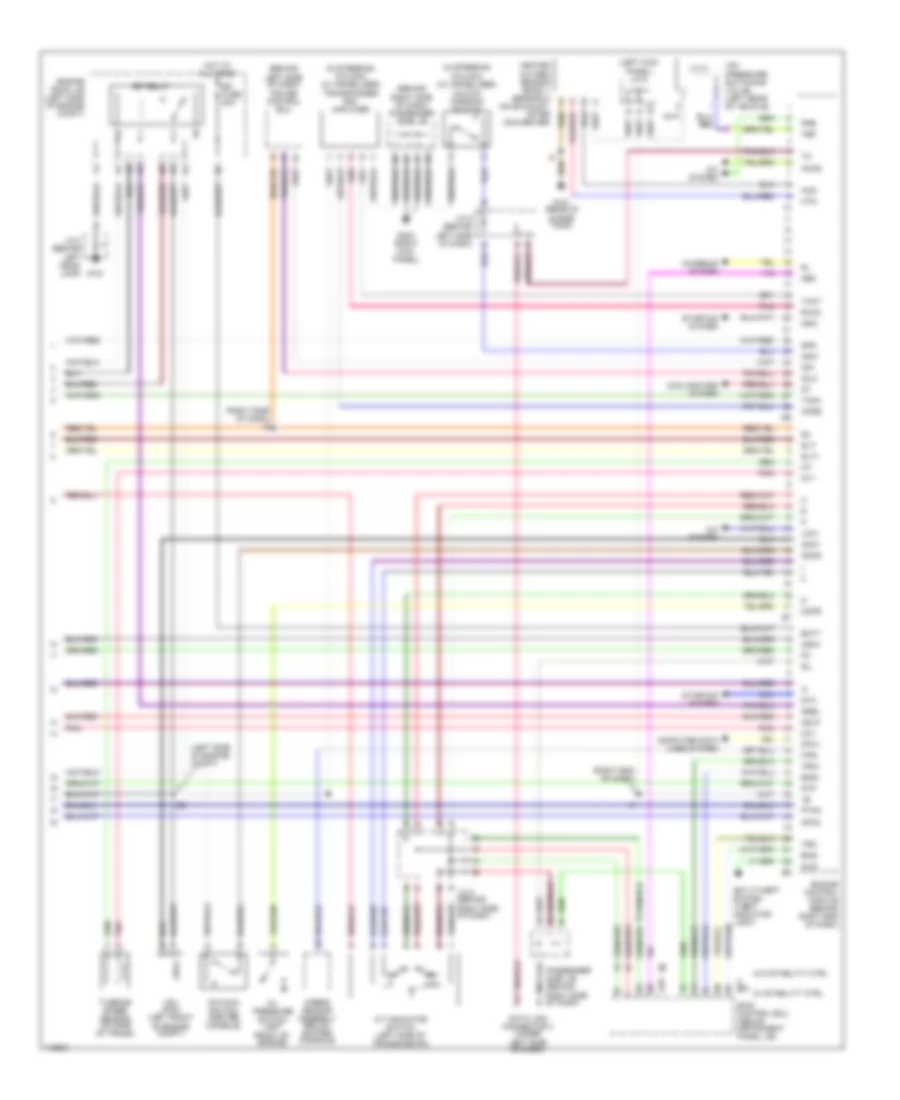
2.4L, Engine Performance Wiring Diagrams (3 of 3) for Toyota Highlander Limited 2001
List of elements for 2.4L, Engine Performance Wiring Diagrams (3 of 3) for Toyota Highlander Limited 2001:
- (center rear of engine) camshaft position sensor
- (left front engine) crankshaft position sensor
- (left rear of engine compt) (evap) vsv
- (left rear of engine compt) mass air flow meter
- (on exhaust manifold) (bank 1, sensor 1) air fuel ratio sensor
- (on exhaust manifold) (bank 2, sensor 1) air fuel ratio sensor
- (on exhaust) (bank 1 sensor 2) heated oxygen sensor
- (on exhaust) (bank 2 sensor 2) heated oxygen sensor
- (right
- (right side of cylinder block)
- (right side of cylinder block) g120
- (right side of dash) i6
- (right side of dash) j/c 7
- A/c system
- A/t indicator switch (left side of transmission)
- A12
- Acmg
- Af1a+
- Af1a-
- Af2+
- Af2-
- Batt
- Ccv
- Charging system
- Computer data lines system
- Data link connector 3 (under left side of dash)
- Dsl
- E04
- E05
- E2g
- E9 (rear of engine)
- Eng+
- Eng-
- Engine control module (behind right end of dash)
- Evp1
- F/ps
- G120
- G22+
- Haf1a
- Haf2a
- Ht1b
- Ht2b
- Igsw
- J/c 6 (left
- Knock sensor
- Lck1
- Mops
- Mpx1
- Mpx2
- Mrel
- Nca a
- Ne+
- Ne-
- Neo
- Odlp
- Ox1b
- Ox2b
- Passenger side j/b (behind
- Pnk
- Psw
- Red
- Right side of dash)
- S10
- S11
- Side of dash)
- Side of engine)
- Sil
- Skid control ecu (above instrument panel j/b)
- Sta
- Starting system
- Stp
- Trc+
- Trc-
- W/ stability ctrl
- W/o stability ctrl
- Wfse
3.0L
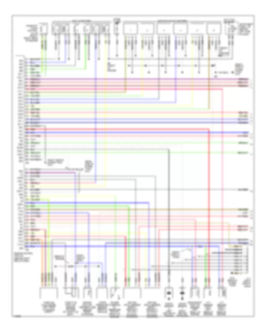
3.0L, Engine Performance Wiring Diagrams (1 of 3) for Toyota Highlander Limited 2001
List of elements for 3.0L, Engine Performance Wiring Diagrams (1 of 3) for Toyota Highlander Limited 2001:
- #10
- #20
- #30
- #40
- #50
- #60
- (front of engine) e6
- (rear of engine)
- (rear side of surge tank) g121
- (right side of dash)
- (right side of dash) i6
- (right side of surge tank) g121
- Aci1
- Acis
- Afl+
- Afl-
- Afr+
- Afr-
- Air fuel ratio sensor (bank 1, sensor 1) (on right
- Air fuel ratio sensor (bank 2, sensor 1) (on left
- Camshaft timing control valve (right) (right rear of engine)
- Crankshaft position sensor (left front of engine)
- Dsl
- E01
- E02
- E03
- E04
- E05
- E2g
- E6 (front of engine)
- Engine control module (behind right end of dash)
- Engine coolant temperature sensor (front of engine)
- Evp1
- Exhaust manifold)
- Fuel injectors
- G121 (rear of surge tank)
- Hafl
- Hafr
- Hot in on or start
- Ig2 fuse 15a
- Igf
- Ignition coils & igniters
- Igt1
- Igt2
- Igt3
- Igt4
- Igt5
- Igt6
- Instrument panel j/b (behind left side of dash)
- J/c 7 (right side of dash)
- Knkl
- Knkr
- Knock sensor (left center of engine)
- Knock sensor (right center of engine)
- Mass air flow meter (left rear of engine compt)
- Nc+
- Nc-
- Nca
- Ne+
- Ne-
- Noise filter
- Oc1+
- Oc1-
- Oc2+
- Oc2-
- Pnk
- Power steering oil pressure switch (front of engine)
- Red
- Rso
- Sl1+
- Sl1-
- Sl2+
- Sl2-
- Tha
- Tho
- Throttle position sensor (on side of throttle body)
- Thw
- Vapor pressure sensor (rear of vehicle)
- Vta1
- Vv1+
- Vvt sensor (left) (left rear of engine)
- Vvt sensor (right) (right rear of engine)
- W2+
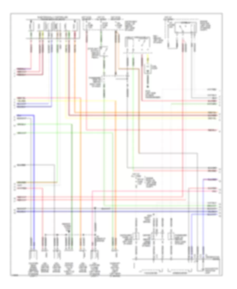
3.0L, Engine Performance Wiring Diagrams (2 of 3) for Toyota Highlander Limited 2001
List of elements for 3.0L, Engine Performance Wiring Diagrams (2 of 3) for Toyota Highlander Limited 2001:
- (rear of surge tank) g121
- (right dash brace)
- A/f fuse 25a
- A/f relay
- C11
- C12
- Camshaft timing control valve (left) (left rear of engine)
- Center j/b (behind upper center of dash)
- Circuit opening relay
- Combination meter
- Counter gear speed sensor (left side of engine compt)
- E10
- E7 (rear of engine)
- Ecu-b fuse 7.5a
- Electronically controlled transmission solenoid
- Engine room j/b (left side of engine compt)
- Engine room r/b (left side of engine compt)
- F13
- Fuel pump
- G10
- G206
- G416 (left side of rear crossmember)
- Hot at all times
- Hot in on or start
- Idle air control valve (on throttle body)
- Ig1 fuse 7.5a
- Ign fuse 7.5a
- Instrument panel j/b (behind left side of dash)
- L11
- M12
- Malfunction indicator lamp
- Passenger side j/b (behind right side of dash)
- Pnk
- R/b 1 (behind left side of dash)
- Red
- Speedometer
- Stop fuse 20a
- Stoplight switch (above brake pedal)
- Tachometer
- Vsv (acis 1) (center top of engine)
- Vsv (acis 2) (center rear of engine)
- Vsv (canister closed valve) (left rear of engine compt)
- Vsv (evap) (center top of engine)
3.0L, Engine Performance Wiring Diagrams (3 of 3) for Toyota Highlander Limited 2001
List of elements for 3.0L, Engine Performance Wiring Diagrams (3 of 3) for Toyota Highlander Limited 2001:
- (behind
- (behind right side of dash) passenger side j/b
- (in steering column) (w/ immobilizer)
- (left kick panel) j/c 9
- (left side of engine compt)
- (right end of dash)
- (right side of dash) i6
- A/c system
- A/t indicator switch (left side of transmission)
- A12
- Acm1
- Acmg
- Airbag sensor assembly (below shifter console)
- Anti-tyheft system (theft indicator light)
- Batt
- Ccv
- Charging system
- Code
- Computer data lines system
- Converter)
- Cooling fans system
- Cruise control ecu
- Data link connector 3 (under left side of dash)
- Efi fuse 20a
- Efi relay
- Eng+
- Eng-
- Engine control module (behind right end of dash)
- Engine room j/b (left side of engine compt)
- F/ps
- G121
- G121 (rear of surge tank)
- G203 (right kick panel)
- Hot at all times
- Hts
- Idlo
- Igsw
- Imld
- J/c 2 (behind left head- lamp)
- J/c 6 (behind left side of dash)
- J/c 8 (behind right side of dash)
- Ksw
- Lck1
- Left side of dash)
- Mops
- Mpx1
- Mpx2
- Mrel
- Neo
- Nsw
- Nt+
- Nt-
- O/d main switch (center console)
- Od1
- Odlp
- Odms
- Oil pressure switch (left front of engine)
- Oxs
- Passenger side j/b (behind right side of dash)
- Pnk
- Pre
- Ptnk
- Rxck
- S10
- S11
- Sil
- Skid control ecu (above instrument panel j/b)
- Slt+
- Slt-
- Spd
- Sta
- Starting system
- Stp
- Tach
- Tbp
- Transponder key amplifier
- Trc+
- Trc-
- Turbine speed sensor (on side of trans)
- Txct
- Unlock warning switch
- Vsv (acm) (left front of engine compt)
- Vsv (pressure switching valve) (left rear of vehicle)
- W/ stability ctrl
- W/o stability ctrl
EXTERIOR LIGHTS
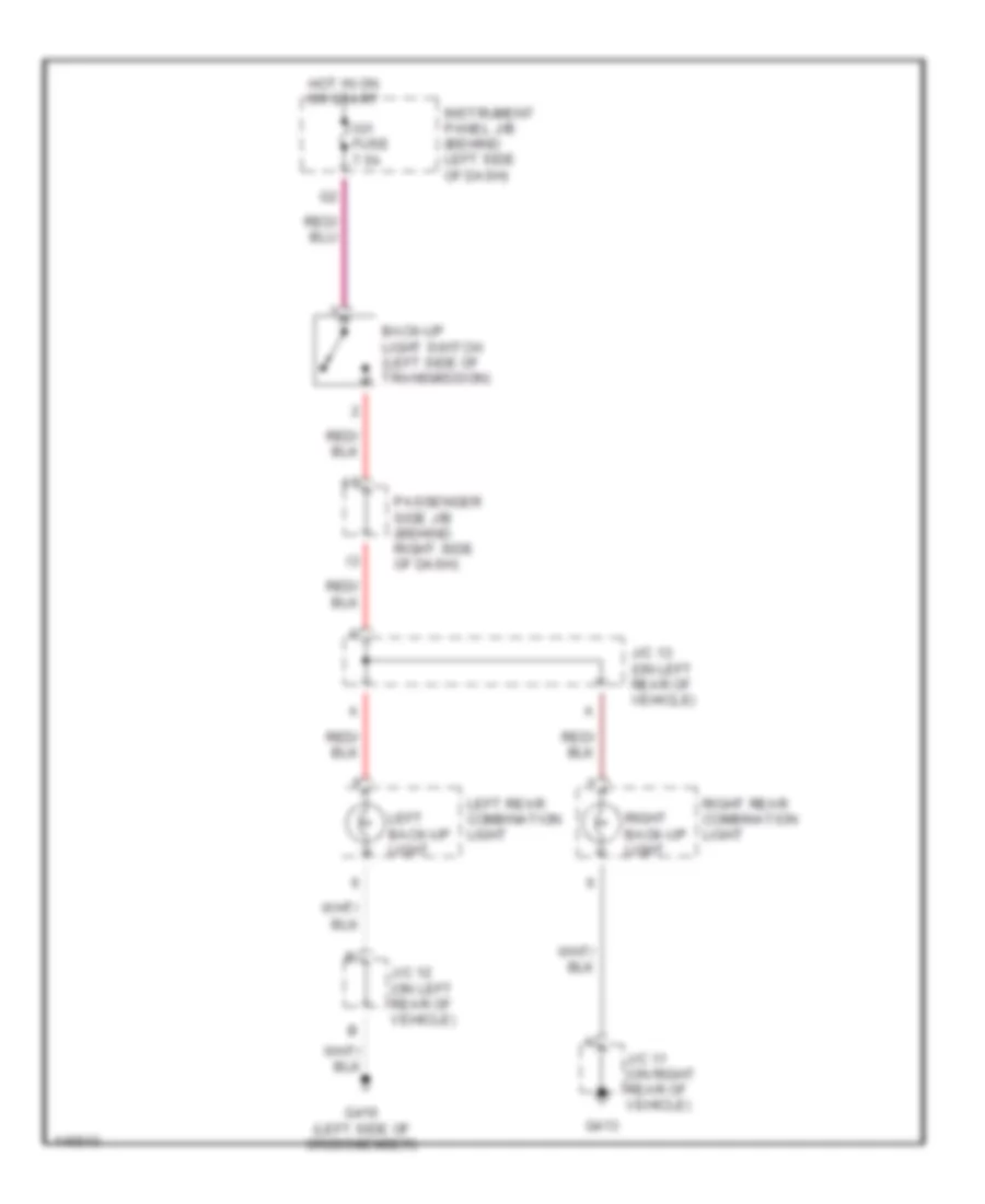
Back-up Lamps Wiring Diagram for Toyota Highlander Limited 2001
List of elements for Back-up Lamps Wiring Diagram for Toyota Highlander Limited 2001:
- Back-up light switch (left side of transmission)
- G413
- G416 (left side of crossmember)
- Hot in on or start
- Ig1 fuse 7.5a
- Instrument panel j/b (behind left side of dash)
- J/c 11 (on right rear of vehicle)
- J/c 12 (on left rear of vehicle)
- J/c 13 (on left rear of vehicle)
- Left back-up light
- Left rear combination light
- Passenger side j/b (behind right side of dash)
- Right back-up light
- Right rear combination light
Exterior Lamps Wiring Diagram for Toyota Highlander Limited 2001
List of elements for Exterior Lamps Wiring Diagram for Toyota Highlander Limited 2001:
- (body harn, right rear of vehilce)
- (on left rear of vehicle) j/c 10
- (part of combo switch) turn signal switch
- Alt fuse 140a
- B10
- B11
- Body ecu (behind right side of dash)
- C10
- Center panel j/b (behind upper center of dash)
- Combination meter
- E10
- Engine room j/b (on left side of eng compt)
- F13
- Fusible link block (on left side of engine compt)
- G10
- G101
- G106
- G200 (left kick panel)
- G206 (right instrument panel brace)
- G411
- G413
- G416 (left side of crossmember)
- Haz
- Hazard fuse 15a
- Hazard switch (a/c control assembly)
- Head
- High mounted stop light
- Hot at all times
- Hot in on or start
- Ig1 fuse 7.5a
- Instrument panel j/b (behind left side of dash)
- J/c 1 (under left headlight)
- J/c 11 (on right rear of vehicle)
- J/c 12 (on left rear of vehicle)
- J/c 13 (left rear of vehicle)
- J/c 14 (left side of back door)
- J/c 3 (on right front corner of eng compt)
- J/c 3 (right side of eng compt)
- Left front park/ turn light
- Left rear combin- ation light
- Left rear side marker light
- License plate light
- Light control switch (part of combination switch)
- M13
- Off
- Passenger side j/b (behind right side of dash)
- Right front park/ turn light
- Right rear combin- ation light
- Right rear side marker light
- Stop
- Stop fuse 20a
- Stop light switch (above brake pedal)
- Tail
- Tail fuse 10a
- Taillight relay
- Trailer tow
- Trly
- Turn
- Turn signal flasher (right of instrument panel j/b)
- Turn signal indicator lights
- W/ w/o trailer tow
Trailer Tow Wiring Diagram for Toyota Highlander Limited 2001
List of elements for Trailer Tow Wiring Diagram for Toyota Highlander Limited 2001:
- Body ecu (behind right side of dash)
- C10
- Center panel j/b (behind upper center of dash)
- D14
- Engine room j/b (on left side of engine compt)
- G10
- G200 (left kick panel)
- G416 (left side of rear crossmember)
- Gnd
- Haz
- Hazard fuse 15a
- Hazard switch (a/c control assembly)
- Hot at all times
- Hot in on or start
- Hot w/ light control switch in head or park
- Ig1 fuse 7.5a
- Instrument panel j/b (behind left side of dash)
- J/c 10 (on left rear of vehicle)
- J/c 12 (left rear of vehicle)
- J/c 13 (on left rear of vehicle)
- J/c 3 (on right side of eng compt)
- Lt/s
- Passenger side j/b (behind right side of dash)
- Red
- Rt/s
- Stop fuse 20a
- Stop- light switch (above brake pedal)
- Stp
- Tail
- Tail fuse 10a
- Towing fuse 20a
- Trailer converter (left side of of cargo area, behind trim)
- Trailer hitch (behind left side of rear bumper)
- Turn signal flasher (behind left end of dash)
- Turn signal switch (part of combo switch)
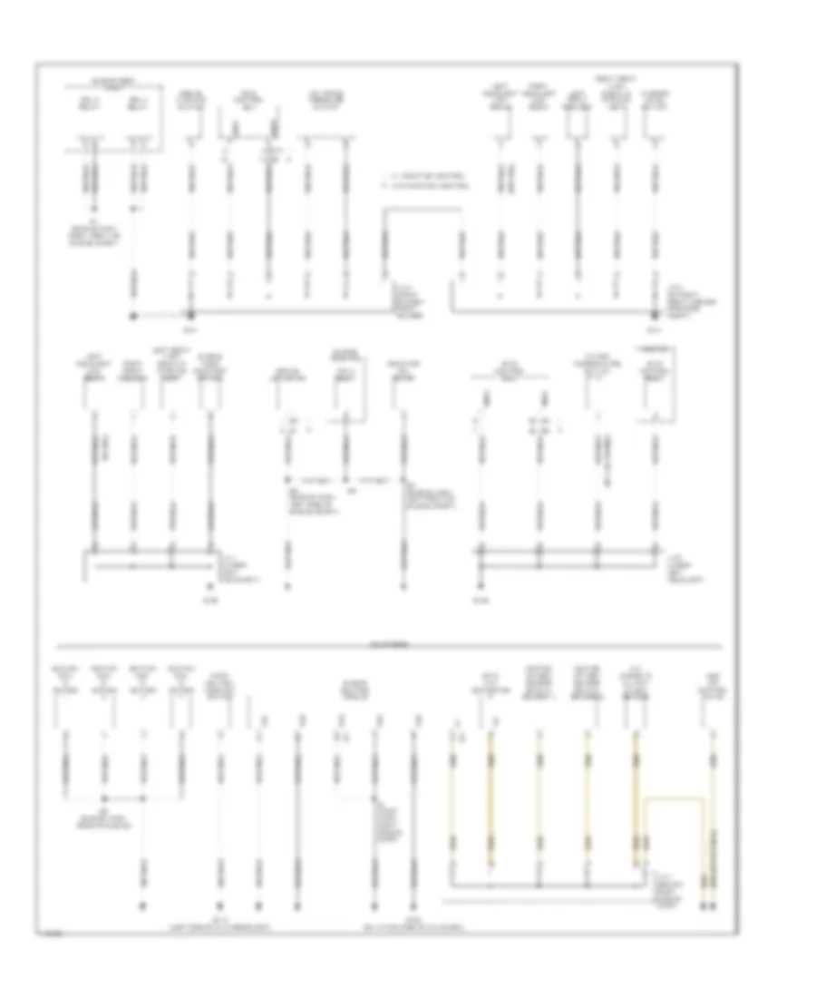
GROUND DISTRIBUTION
Ground Distribution Wiring Diagram (1 of 4) for Toyota Highlander Limited 2001
List of elements for Ground Distribution Wiring Diagram (1 of 4) for Toyota Highlander Limited 2001:
- (w/ 3.ol engine)
- (w/ drl)
- (w/o drl)
- 2.4l engine
- A/c magnetic clutch & lock sensor
- A/c triple pressure switch
- Abs r/b
- Brake actuator
- Brake warning switch
- Data link connector
- Drl 3 relay
- Drl 4 relay
- E01
- E02
- E03
- E04
- E05
- E1 (engine harn, right front of engine compt)
- E2 (engine harn, left front of engine compt)
- E5 (engine harn, left side of engine compt)
- E9 (engine harn, rear of engine)
- Engine control module
- Engine hood courtesy switch
- Engine room r/b
- Engine room r/b 3
- Fan 2 relay
- G101
- G106
- G112 (left side of cylinder block)
- G132 (on intake side of cyl block)
- Gnd1
- Gnd2
- Gnd3
- Gnd4
- Heated oxygen sensor (bank 2, sensor 1)
- Heated oxygen sensor (bank 2, sensor 2)
- I6 (dash harn, right side of dash)
- Idle air control valve
- Ignition coil & igniter
- J/c 1 (under left headlight)
- J/c 2 (under left headlight)
- J/c 3 (on right front corner of engine compt)
- J/c 4 (front of right front fender)
- J/c 7 (behind right side of dash)
- Left front foglight
- Left front turn signal & parking light
- Left headlight (low beam)
- Park/ neutral position switch
- Radiator fan motor
- Right front foglight
- Right front turn signal & parking light
- Right headlight (low beam)
- S12
- Skid control ecu
- Skid control relay
- W/ traction control
- W/o traction control
- Washer level switch
- Water temperature switch
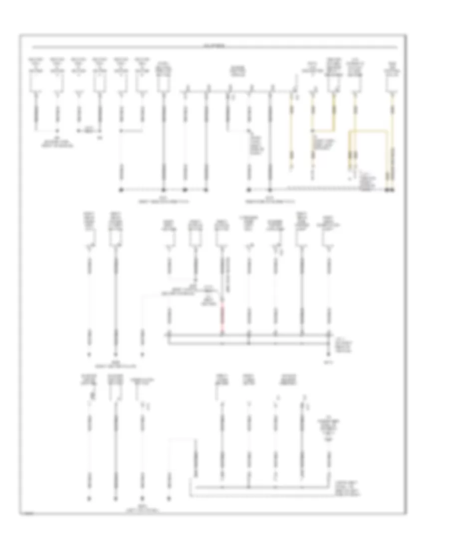
Ground Distribution Wiring Diagram (2 of 4) for Toyota Highlander Limited 2001
List of elements for Ground Distribution Wiring Diagram (2 of 4) for Toyota Highlander Limited 2001:
- (w/ seat heater)
- (w/o seat heater)
- 3.0l engine
- A/c magnetic clutch & lock sensor
- A17
- Air bag sensor assembly
- B3 (body harn, center console)
- Blower control switch
- Blower motor control
- C13
- Combination switch
- D14
- Data link connector
- E01
- E02
- E03
- E04
- E05
- E6 (engine harn, front of engine)
- Engine control module
- Front wiper deicer
- Front wiper motor
- G121 (rear side of surge tank)
- G121 (right side of surge tank)
- G200 (left kick panel)
- G305 (right center pillar)
- G413
- Gnd
- Heated oxygen sensor (bank 1, sensor 2)
- I6 (dash harn, right side of dash)
- I8 (dash harn, right end of dash)
- Idle air control valve
- Ignition coil & igniter
- Instrument panel j/b (behind left side of dash)
- J/c 11 (on right rear of vehicle)
- J/c 7 (behind right side of dash)
- L10
- Park/ neutral position switch
- Right buckle switch
- Right rear combination light
- Right rear door lock unit
- Right rear power window switch
- Right rear side marker light
- Right seat heater
- S23
- Stereo power amplifier
- To passenger side j/b (diagram 3 of 4)
- Wireless door lock ecu
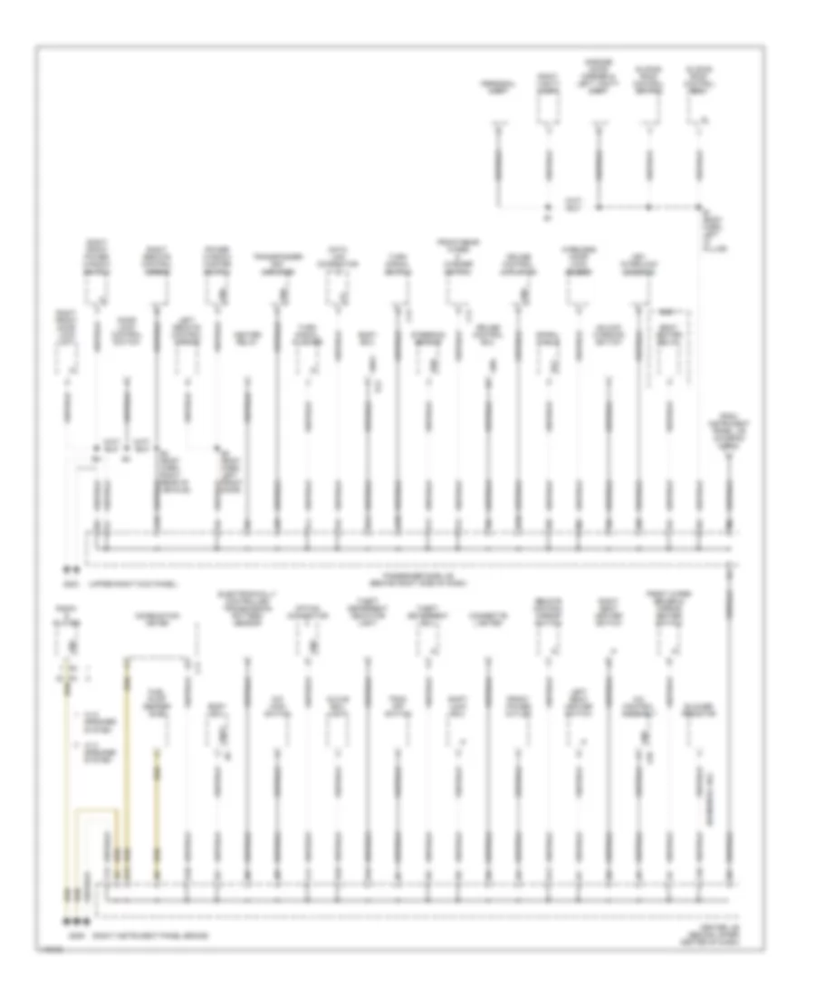
Ground Distribution Wiring Diagram (3 of 4) for Toyota Highlander Limited 2001
List of elements for Ground Distribution Wiring Diagram (3 of 4) for Toyota Highlander Limited 2001:
- (right instrument panel brace)
- (upper right kick panel)
- (w/ manual a/c)
- A/c control assembly
- A10
- B1 (body harn, left "a" pillar)
- B12
- B2 (body harn, left front door)
- B4 (body harn, right rear of vehicle)
- Blower resistor
- Body ecu
- C11
- C13
- C14
- Center j/b (behind upper center of dash)
- Cigarette lighter
- Combination meter
- Cruise control actuator
- Cruise control ecu
- Data link connector
- Door lock control switch
- E10
- E11
- Ecc
- Electronically controlled transmission pattern sensor
- Ess
- F11
- F13
- From instrument panel j/b (diagram 2 of 4)
- Front power outlet
- Front wiper deicer & mirror heater switch
- Front/rear wiper & washer switch
- Fuel pump sender (sub)
- G10
- G203
- G206
- Garage door opener & left vanity light
- Glove box light
- Gnd
- Gnd1
- Gnd2
- H10
- H11
- Heater relay
- J10
- J11
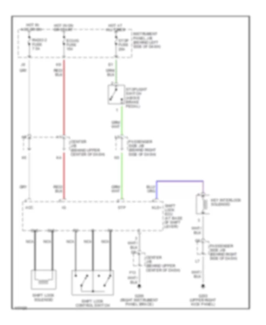
- Key interlock solenoid
- L10
- Left remote control mirror
- Left seat heater switch
- O/d main switch
- Option connector
- Passenger side j/b (behind right side of dash)
- Personal light
- Power window master switch
- R/b 1
- Radio & player
- Remote control mirror switch
- Right front door lock unit
- Right front power window switch
- Right remote control mirror
- Right seat heater switch
- Right vanity light
- Seat heater relay
- Shift lock ecu
- Sliding roof control ecu
- Sliding roof control switch
- Spiral cable
- Steering sensor
- Theft deterrent ecu
- Theft deterrent indicator light
- Trac off switch
- Transponder key amplifier
- Turn signal flasher
- Turn signal switch
- Unlock warning switch
- W/ 6 speaker system
- W/ 8 speaker system
- Wireless door lock buzzer
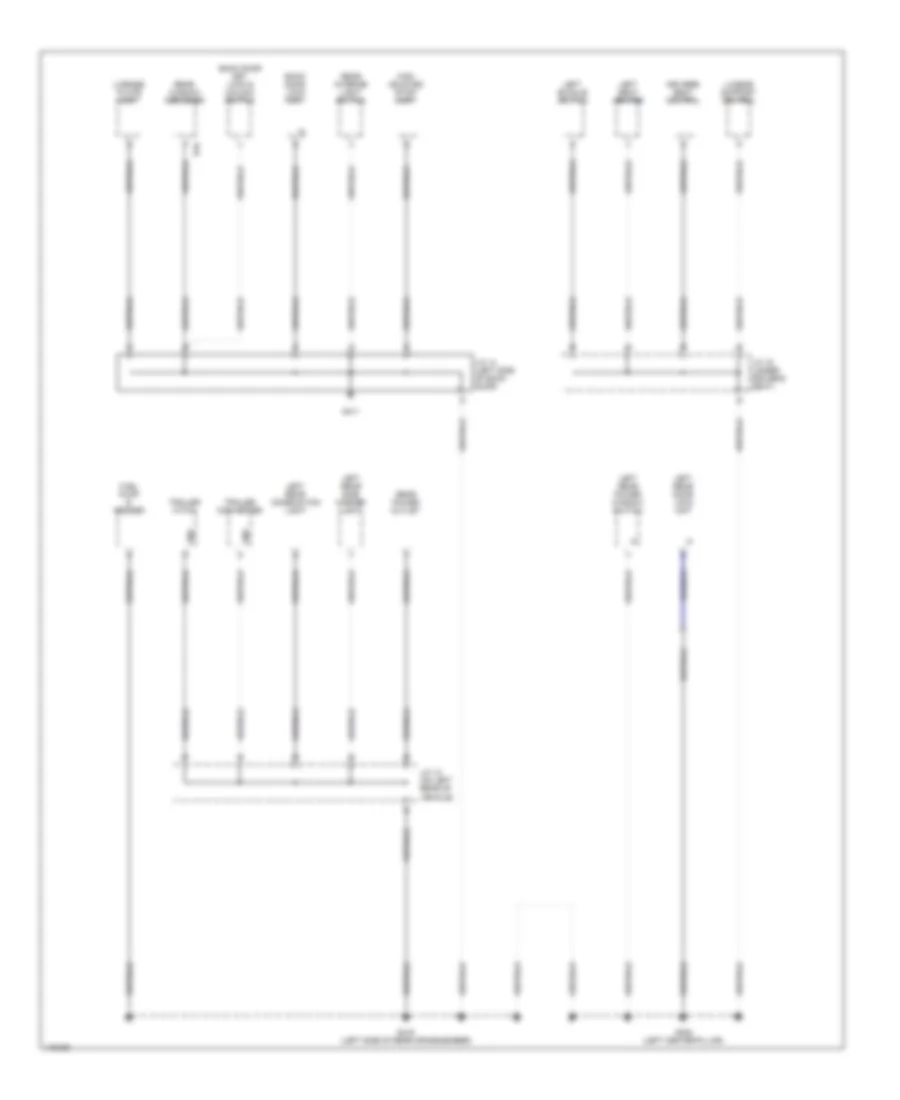
Ground Distribution Wiring Diagram (4 of 4) for Toyota Highlander Limited 2001
List of elements for Ground Distribution Wiring Diagram (4 of 4) for Toyota Highlander Limited 2001:
- Back door key lock & unlock switch
- Back door lock unit
- Driver's seat control
- Fuel pump & sender
- G308 (left center pillar)
- G411
- G416 (left side of rear crossmember)
- Gnd
- High mounted stop- light
- J/c 12 (on left rear of vehicle)
- J/c 14 (left side of back door)
- J/c 15 (under driver's seat)
- Left buckle switch
- Left rear combination light
- Left rear door lock unit
- Left rear power window switch
- Left rear side marker light
- Left seat heater
- License plate light
- Lumbar support control
- R16
- Rear interior light switch
- Rear power outlet
- Rear window defogger
- Trailer converter
- Trailer hitch
HEADLIGHTS
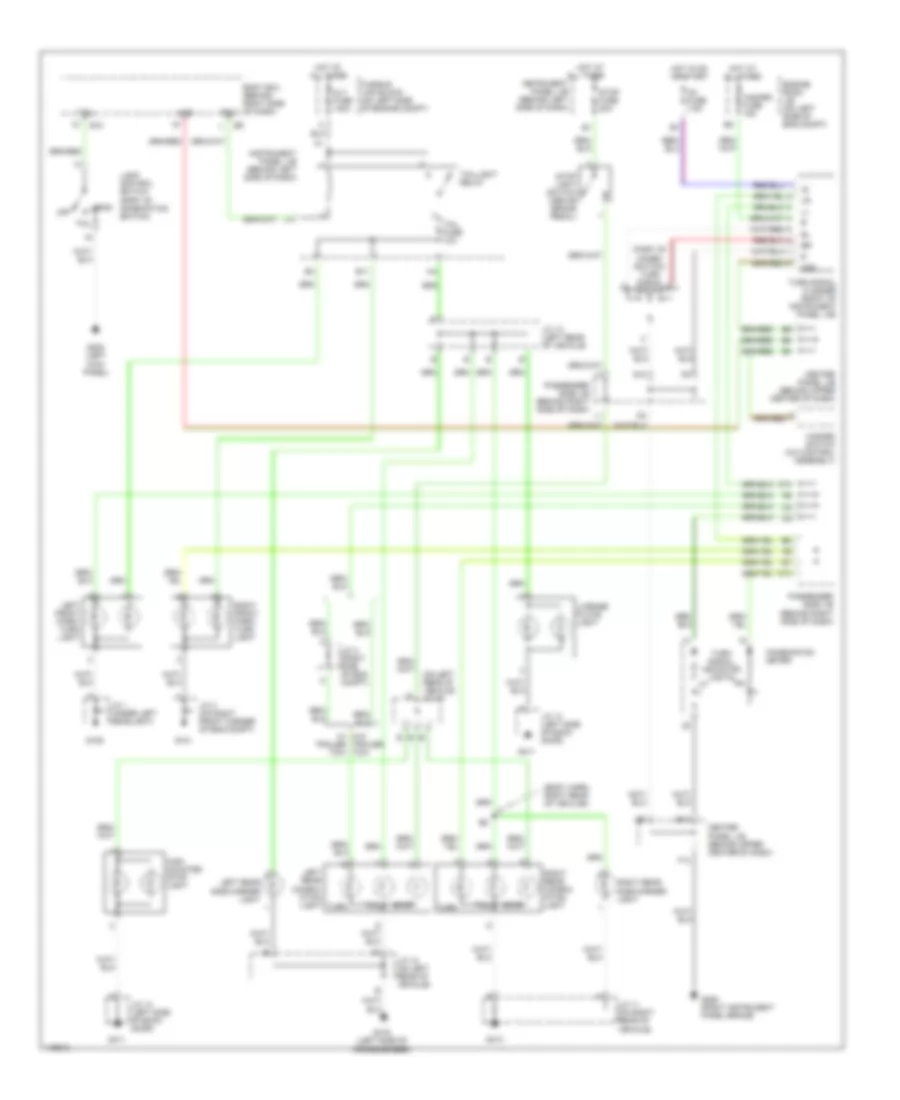
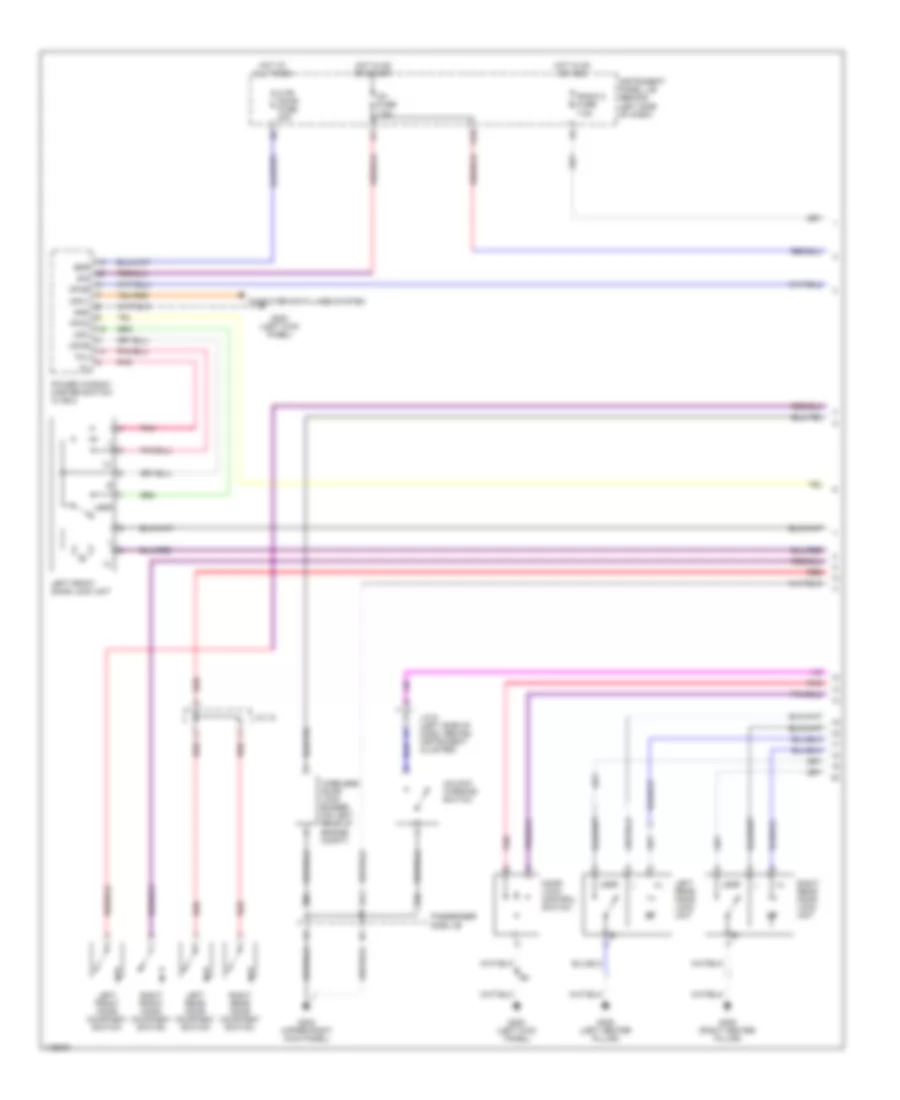
Headlight Wiring Diagram, with DRL for Toyota Highlander Limited 2001
List of elements for Headlight Wiring Diagram, with DRL for Toyota Highlander Limited 2001:
- (center of firewall) e3
- (right front of engine compt) engine room r/b 3
- A10
- A13
- Acc
- Alt fuse 100a
- Auto
- Automatic light control sensor (upper left side of dash)
- B10
- B11
- B12
- Becu
- Body ecu (behind right side of dash)
- C11
- C12
- Center j/b (behind center of dash)
- Cltb
- Clte
- Clts
- Combination meter
- Combination switch
- Dcty
- Dimmer switch
- Drl
- Drl 2 relay
- Drl 3 relay
- Drl 4 relay
- Drl fuse 7.5a
- E4 (left rear of engine compt)
- Ecu-b fuse 7.5a
- Engine room j/b (left side of engine compt)
- Engine room r/b (left side of engine compt)
- Ffog
- Flash
- Fog light relay
- Foglight switch
- Fr fog fuse 10a
- Fusible link box (left side of engine compt)
- G10
- G101 (front of right front fender)
- G101 (right front of engine compt)
- G106 (under left headlamp)
- G200 (left kick panel)
- G203 (upper right kick panel)
- Gnd1
- H11
- Head
- Head lp lh lwr fuse 15a
- Head lp lh upr fuse 10a
- Head lp rh lwr fuse 15a
- Head lp rh upr fuse 10a
- Headlamp relay
- High
- High beam indicator
- Hot at all times
- Hot in on or acc
- Hot in on or start
- Hrly
- Ig1 fuse 7.5a
- Instrument panel j/b (behind left side of dash)
- J/c 1
- J/c 3
- K10
- Left fog light
- Left front door courtesy switch
- Left high beam headlight
- Left low beam head- light
- Light control switch
- Low
- Main fuse 40a
- Of engine compt)
- Off
- Parking brake switch
- Passenger side j/b (behind right side of dash)
- Pkb
- Radio 2 fuse 7.5a
- Red
- Right fog light
- Right high beam headlight
- Right low beam head- light
- Tail
- Tail fuse 10a
- Tail light relay
- Trly
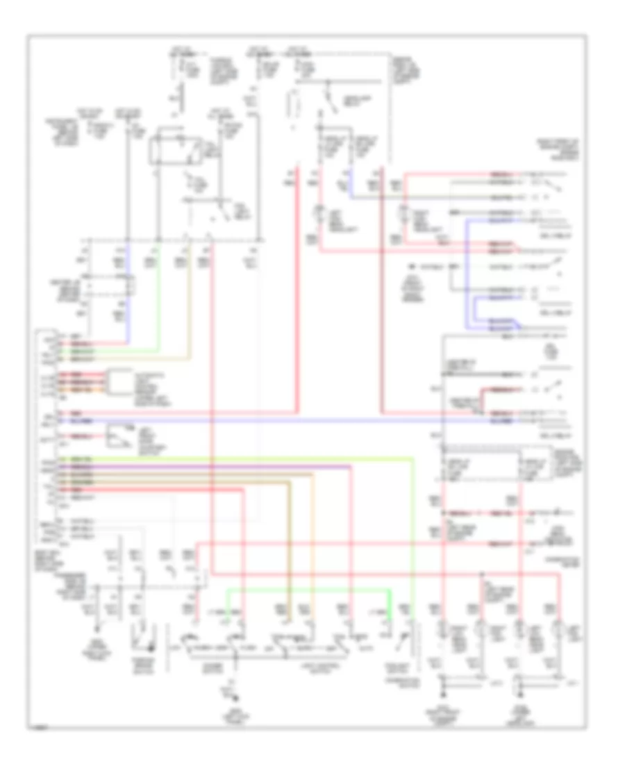
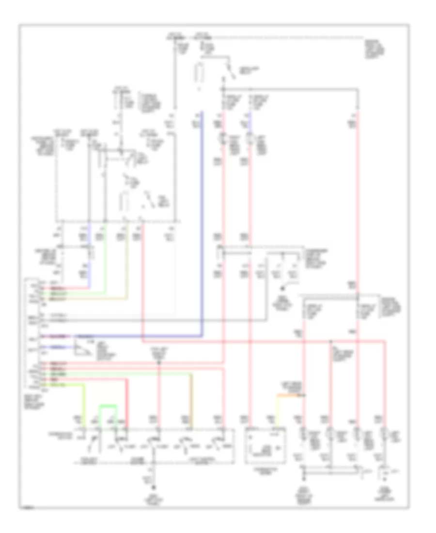
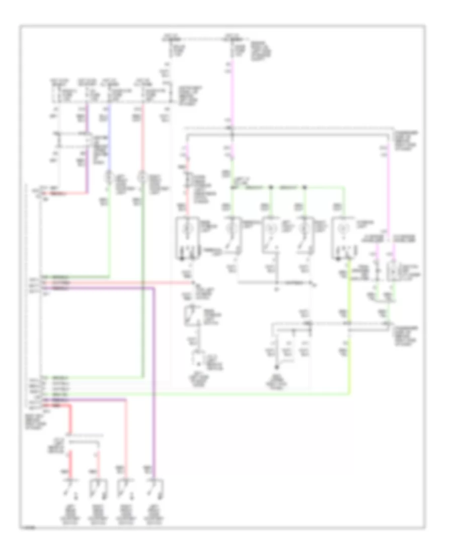
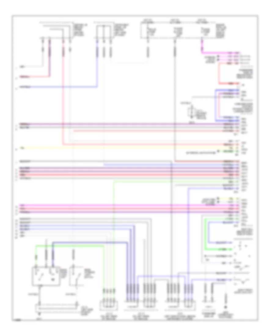
Headlight Wiring Diagram, without DRL for Toyota Highlander Limited 2001
List of elements for Headlight Wiring Diagram, without DRL for Toyota Highlander Limited 2001:
- (left rear of engine compt) e4
- (top left side of dash) i3
- A10
- A13
- Acc
- Alt fuse 100a
- B10
- B11
- B12
- Becu
- Body ecu (behind right side of dash)
- C11
- C12
- Center j/b (behind center of dash)
- Combination meter
- Combination switch
- Dcty
- Dimmer switch
- E4 (left rear of engine compt)
- Ecu-b fuse 7.5a
- Engine room j/b (left side of engine compt)
- Engine room r/b (left side of engine compt)
- Ffog
- Flash
- Fog light relay
- Foglight switch
- Fr fog fuse 10a
- Fusible link box (left side of engine compt)
- G10
- G101 (right front of engine compt)
- G106 (under left headlamp)
- G200 (left kick panel)
- G203 (upper right kick panel)
- Gnd1
- H11
- Head
- Head lp lh lwr fuse 15a
- Head lp lh upr fuse 10a
- Head lp rh lwr fuse 15a
- Head lp rh upr fuse 10a
- Headlamp relay
- High
- High beam indicator
- Hot at all times
- Hot in on or acc
- Hot in on or start
- Hrly
- Ig1 fuse 7.5a
- Instrument panel j/b (behind left side of dash)
- J/c 1
- J/c 3
- K10
- Left fog light
- Left front door courtesy switch
- Left high beam head- light
- Left low beam head- light
- Light control switch
- Low
- Main fuse 40a
- Off
- Passenger side j/b (behind right side of dash)
- Radio 2 fuse 7.5a
- Red
- Right fog light
- Right high beam head- light
- Right low beam head- light
- Tail
- Tail fuse 10a
- Tail light relay
- Trly
HORN
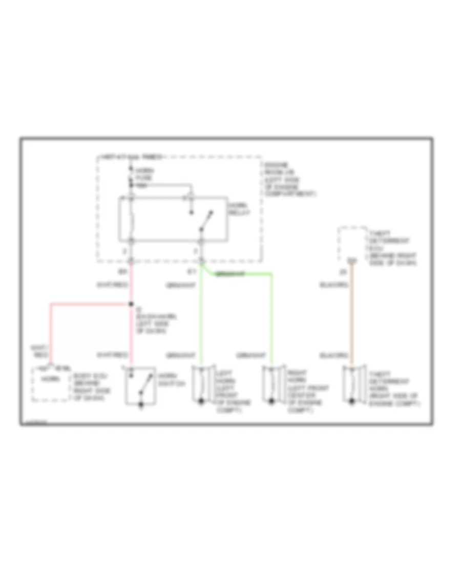
Horn Wiring Diagram for Toyota Highlander Limited 2001
List of elements for Horn Wiring Diagram for Toyota Highlander Limited 2001:
- (left front center of engine compt)
- B12
- Body ecu (behind right side of dash)
- Engine room j/b (left side of engine compartment)
- Horn
- Horn fuse 10a
- Horn relay
- Horn switch
- Hot at all times
- I2 (dash harn, left side of dash)
- Left horn (left front of engine compt)
- Right horn
- Theft deterrent ecu (behind right side of dash)
- Theft deterrent horn (right side of engine compt)
INSTRUMENT CLUSTER
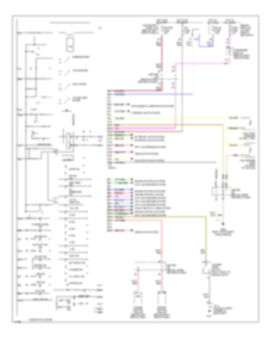
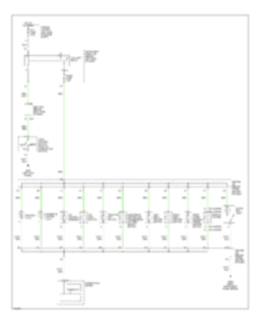
Instrument Cluster Wiring Diagram for Toyota Highlander Limited 2001
List of elements for Instrument Cluster Wiring Diagram for Toyota Highlander Limited 2001:
- 2 ind
- A/t oil temp ind
- A10
- A11
- A12
- A13
- A14
- A15
- A16
- A17
- A18
- A19
- A20
- A21
- A22
- Abs ind
- Air bag ind
- Air conditioning system
- Anti-lock brakes system
- B10
- B11
- B12
- B13
- B14
- B15
- B16
- Beam ind
- Brake ind
- Buzzer
- C11 conn a
- Center j/b (behind upper center of dash)
- Charge ind
- Combination meter
- Computer data lines system
- Cruise control module (behind left side of dash)
- Cruise control system
- Cruise ind
- D ind
- D11
- Dome fuse 10a
- Door ind
- E10
- Ect snow ind
- Ecu-b fuse 7.5a
- Engine control module (behind right side of dash)
- Engine controls system
- Engine room j/b (on left side of eng compt)
- Exterior lights system
- F13
- Fr fog ind
- Fuel gauge
- Fuel ind
- Fuel pump & sender (in fuel tank)
- Fuel sender (sub) (at rear of vehicle)
- G10
- G101
- G206 (right instrument panel brace)
- Headlights system
- Heater fuse 15a
- Hot at all times
- Hot in on or start
- Ign fuse 7.5a
- Instrument panel j/b (behind left side of dash)
- Interior lights system
- J/c 3 (on right front corner of eng compt)
- K13
- L ind
- Lcd
- Left turn ind
- Malfunction ind
- N ind
- O/d off ind
- Oil level ind
- Oil pressure ind
- P ind
- Passenger side j/b (behind right side of dash)
- R ind
- Rheostat
- Right turn ind
- Seat belt ind
- Slip ind
- Spd
- Speedometer
- Tachometer
- Tail ind
- Trac off ind
- Vsc ind
- Washer level ind
- Washer level switch (right front of engine compt)
- Water temp gauge
INTERIOR LIGHTS
Courtesy Lamps Wiring Diagram for Toyota Highlander Limited 2001
List of elements for Courtesy Lamps Wiring Diagram for Toyota Highlander Limited 2001:
- (left "a" pillar) b1
- A10
- Acc
- B11
- B12
- B6 (top left of rear hatch)
- Bcty
- Becu
- Body ecu (behind right side of dash)
- Center j/b (behind upper center of dash)
- D12
- D13
- Dcty
- Dcyl
- Diode (rear interior light) (near rear hatch, in roof)
- Dome fuse 10a
- Door
- Door d fr fuse 20a
- Door p fr fuse 25a
- Ecu-b fuse 7.5a
- Engine room j/b (left side of engine compt)
- G10
- G203 (upper right kick panel)
- G411 (left side of back door)
- Gnd1
- H11
- Hot at all times
- Hot in on or acc
- Hot in on or start
- Ig1 fuse 7.5a
- Ignition key cylinder illum
- Ile
- Instrument panel j/b (behind left side of dash)
- Interior light
- J/c 12 (left rear of vehicle)
- J/c 14 (left rear of vehicle)
- K10
- Left front door courtesy light
- Left front door courtesy switch
- Left rear door courtesy switch
- Left vanity light
- Off
- Passenger side j/b (behind right side of dash)
- Pcty
- Pcyl
- Personal light
- Radio 2 fuse 7.5a
- Rcty
- Rear interior light
- Rear interior light switch
- Red
- Right front door courtesy light
- Right front door courtesy switch
- Right rear door courtesy switch
- Right vanity light
- Tran- sponder key amplifier
- W/ engine immobilizer
- W/o engine immobilizer
Instrument Illumination Wiring Diagram for Toyota Highlander Limited 2001
List of elements for Instrument Illumination Wiring Diagram for Toyota Highlander Limited 2001:
- (6 spkr)
- (8 spkr)
- A/c control assembly
- A11
- Alt fuse 100a
- Ashtray illum
- B10
- Body ecu (behind right side of dash)
- C11
- Center j/b (behind upper center of dash)
- Cigarette lighter illum
- Combination meter
- Electronic controlled transmission pattern select switch
- F13
- Front wiper deicer & mirror heater switch
- Fusible link box (left side of engine compt)
- G200 (left kick panel)
- G206 (right instrument panel brace)
- Glove box light
- H10
- Head
- Hot at all times
- Instrument panel j/b (behind left side of dash)
- Left seat heater switch
- Light control switch (part of combination switch)
- O/d main switch
- Off
- Panel fuse 7.5a
- Radio & player
- Rheostat
- Right seat heater switch
- Tail
- Taillight relay
- Traction off switch
POWER DISTRIBUTION
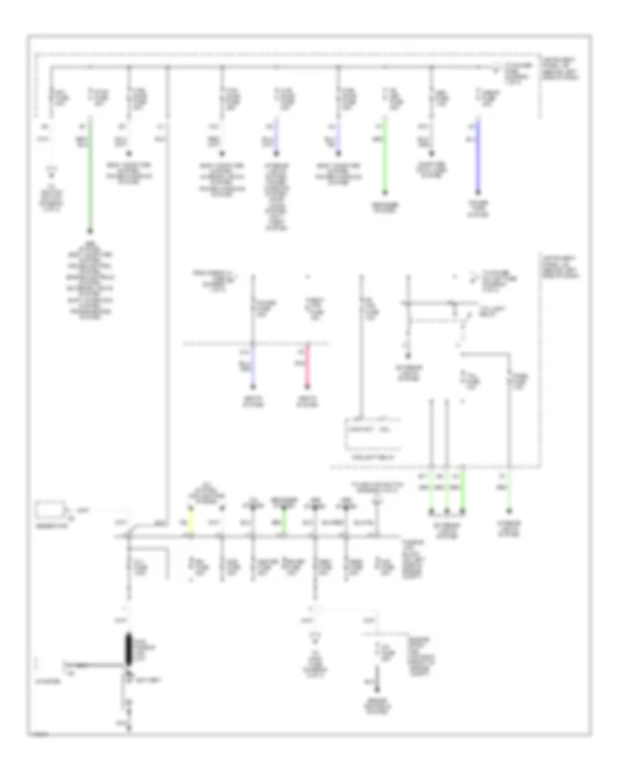
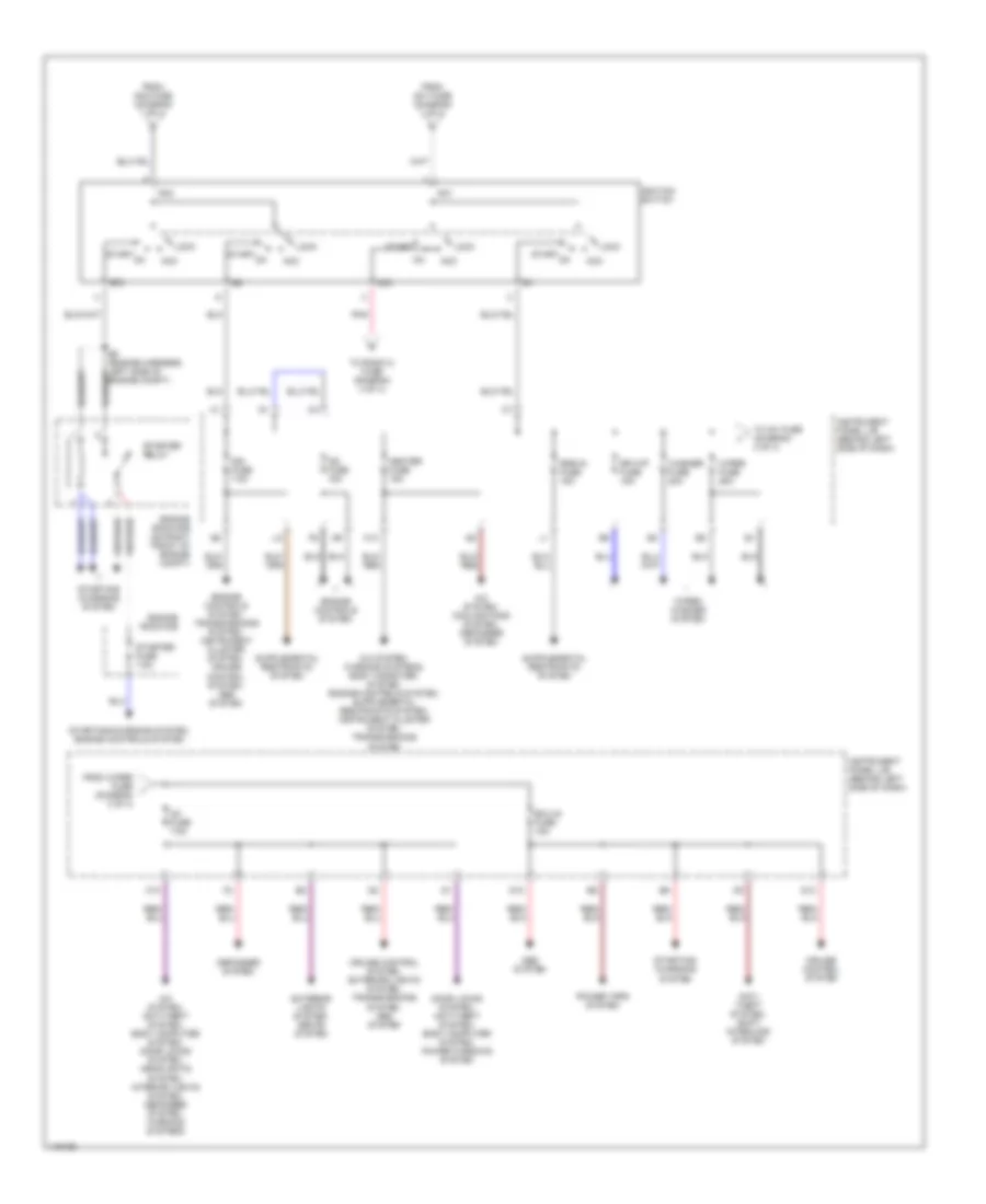
Power Distribution Wiring Diagram (1 of 4) for Toyota Highlander Limited 2001
List of elements for Power Distribution Wiring Diagram (1 of 4) for Toyota Highlander Limited 2001:
- A/c system
- A/c system, cooling fans system
- A/f fuse 25a
- Abs system
- Abs system, body computer system, cruise control system, engine controls system, exterior lights system, shift interlock system, transmissions system
- Abs1 fuse 40a
- Abs2 fuse 40a
- Alt fuse 140a
- Am1 fuse 40a
- Am2 fuse 30a
- B11
- Battery
- Body computer system, interior lights system, power windows system
- Body computer system, power windows system
- Cds fuse 30a
- Coil
- Computer data lines system
- Contact
- D fr door fuse 20a
- D rr door fuse 20a
- D12
- D13
- Defogger system
- E10
- Engine controls system
- Engine room r/b (on right front of engine compt)
- Exterior lights system
- Foglight relay
- Fr def fuse 20a
- Fr fog fuse 10a
- From s/roof fuse d (diagram 1 of 4)
- Fusible link block (on left side of engine compt)
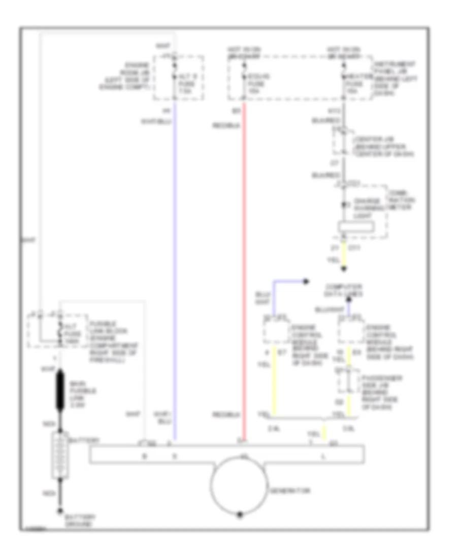
- Generator
- Heater fuse 50a
- Instrument panel j/b (behind left side of dash)
- Interior lights system
- Interior lights system, power windows system, door locks system, anti- theft system
- Main fusible link 3.0w
- Nca
- Obd fuse 7.5a
- P fr door fuse 25a
- P rr door fuse 20a
- Panel fuse 7.5a
- Pnk
- Power fuse 30a
- Power tops system
- Rdi fuse 30a
- Rr def fuse 30a
- S/roof fuse 20a
- Seat htr fuse 15a
- Seats system
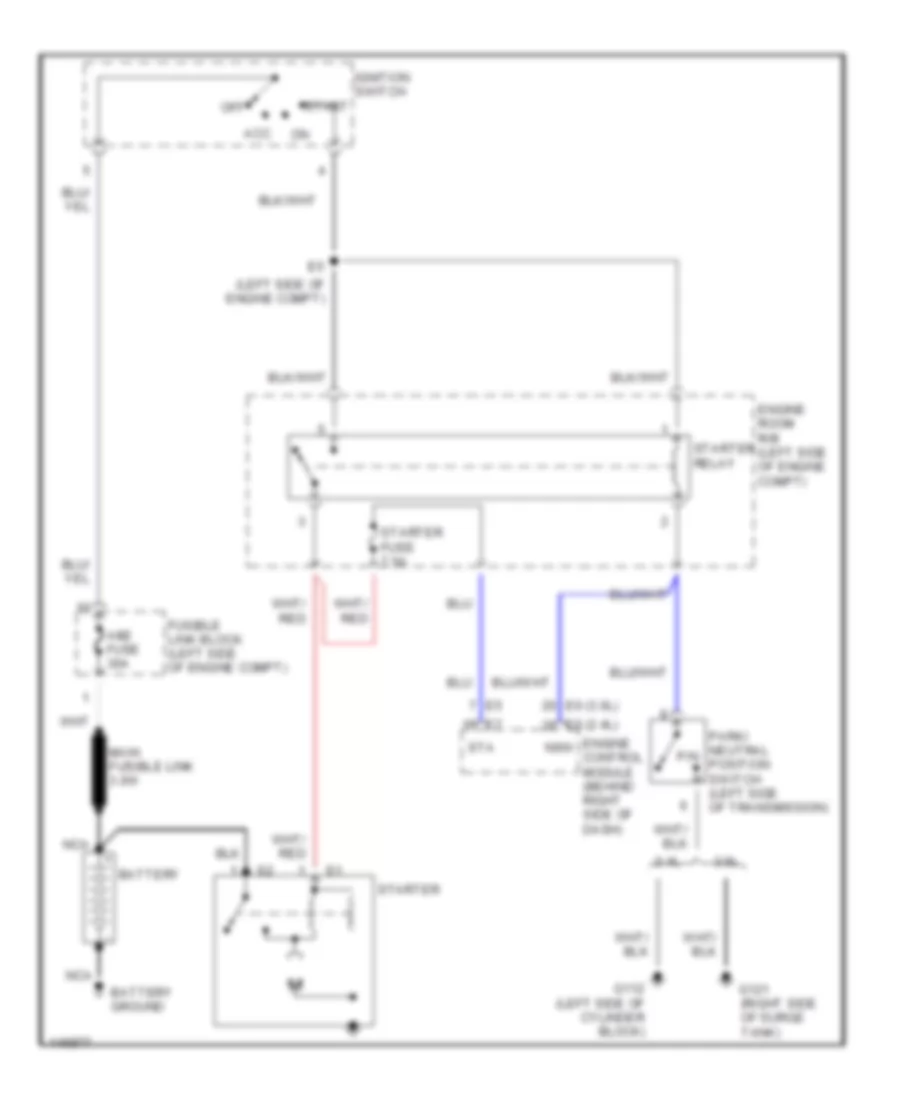
- Starter
- Stop fuse 20a
- Tail fuse 10a
- Taillight relay
- To ignition switch (diagram 3 of 4)
- To main fuse (diagram 2 of 4)
- To power fuse (diagram 1 of 4)
- To power outlet fuse (diagram 4 of 4)
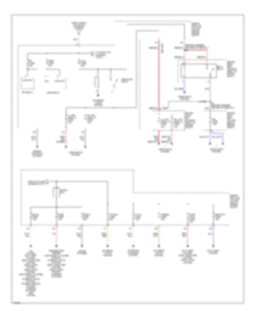
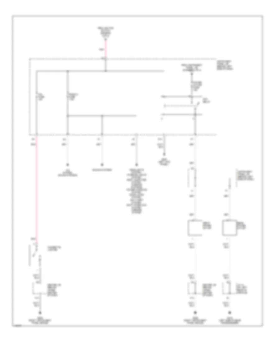
Power Distribution Wiring Diagram (2 of 4) for Toyota Highlander Limited 2001
List of elements for Power Distribution Wiring Diagram (2 of 4) for Toyota Highlander Limited 2001:
- (w/ drl)
- (w/o drl)
- A/c system, anti-theft system, body computer system, door locks system, headlights system, instrument cluster system, interior lights system, power windows system, warning systems, abs system
- Alt-s fuse 7.5a
- Anti-theft system
- Anti-theft system, body computer system, door locks system
- Coil
- Contact
- Dome fuse 10a
- Door lock fuse 20a
- Drl 2 relay
- Drl fuse 7.5a
- Ecu-b fuse 7.5a
- Efi fuse 20a
- Efi relay
- Engine controls system
- Engine room j/b (on left side of engine compt)
- Engine room r/b (on right front of engine compt)
- Engine room r/b 3 (on left side of engine compt)
- Engine room r/b 3 (on right front of engine compt)
- Exterior lights system
- From fusible link block (diagram 1 of 4)
- From main fuse g (diagram 2 of 4)
- Garage door opener, instrument cluster system, interior lights system, body computer system, door locks system, warning systems
- Hazard fuse 15a
- Headlamp relay
- Headlights system
- Horn fuse 10a
- Horn relay
- Lh lwr head lp fuse 10a
- Lh upr head lp fuse 10a
- Main fuse 40a
- Radio 1 fuse 25a
- Rh lwr head lp fuse 10a
- Rh upr head lp fuse 10a
- Security fuse 15a
- Short pin
- Sound systems
- Starting/ charging system
- To short pin (diagram 2 of 4)
- Towing fuse 20a
Power Distribution Wiring Diagram (3 of 4) for Toyota Highlander Limited 2001
List of elements for Power Distribution Wiring Diagram (3 of 4) for Toyota Highlander Limited 2001:
- A/c system, anti-theft system, body computer system, door locks system, headlights system, interior lights system, defogger system, warning systems
- A/c system, cooling fans system, defogger system
- Abs system
- Acc
- Am1
- Am2
- Anti- theft system, shift interlock system
- Cruise control system
- Cruise control system, exterior lights system, transmissions system, abs system
- D10
- Defogger system
- Door locks system, anti-theft system, body computer system, power windows system
- E5 (engine harness, left side of engine compt)
- Ecu-ig fuse 15a
- Engine controls system
- Engine controls system, transmissions system, instrument cluster system, cruise control system, abs system
- Engine room r/b
- Engine room r/b (on right front of engine compt)
- Exterior lights system, seats system
- From am1 fuse (diagram 1 of 4)
- From am2 fuse (diagram 1 of 4)
- From wiper fuse (diagram 3 of 4)
- G13
- Heater fuse 15a
- Ig1
- Ig1 fuse 7.5a
- Ig2
- Ig2 fuse 15a
- Ign fuse 7.5a
- Ignition switch
- Instrument panel j/b (behind left side of dash)
- K10
- K13
- Lock
- Pnk
- Power tops system
- Rr wip fuse 15a
- Srs-ig fuse 15a
- St2
- Start
- Starter fuse 7.5a
- Starter relay
- Starting/ charging system
- Starting/charging system, engine controls system
- To ig1 fuse (diagram 3 of 4)
- To radio 2 fuse (diagram 4 of 4)
- Washer fuse 20a
- Wiper fuse 25a
- Wiper/ washer system
Power Distribution Wiring Diagram (4 of 4) for Toyota Highlander Limited 2001
List of elements for Power Distribution Wiring Diagram (4 of 4) for Toyota Highlander Limited 2001:
- A/c system, sound systems
- Acc relay
- Center j/b (behind upper center of dash)
- Cig fuse 15a
- Cigarette lighter
- D14
- F13
- From ignition switch (diagram 3 of 4)
- From instrument panel j/b (diagram 1 of 4)
- Front power outlet
- G200 (left kick panel)
- G206 (right instrument panel brace)
- G416 (left side of rear crossmember)
- Headlights system, interior lights system, body computer system, warning systems, power windows system, door locks system, anti-theft system, shift interlock system, mirrors system
- Instrument panel j/b (behind left side of dash)
- J/c 12 (on left rear of vehicle)
- Pnk
- Power outlet fuse 15a
- Radio 2 fuse 7.5a
- Rear power outlet
- Sound systems
POWER DOOR LOCKS
Power Door Lock Wiring Diagram, with Keyless Entry (1 of 2) for Toyota Highlander Limited 2001
List of elements for Power Door Lock Wiring Diagram, with Keyless Entry (1 of 2) for Toyota Highlander Limited 2001:
- Bdr
- Computer data lines system
- Cpub
- D fr door fuse 20a
- Door lock control switch
- G200 (left kick panel)
- G203 (upper right kick panel)
- G305 (right center pillar)
- G308 (left center pillar)
- Gnd
- H11
- Hot at all times
- Hot in on or acc
- Hot in on or start
- Ig1 fuse 7.5a
- Instrument panel j/b (behind left side of dash)
- J/c 12
- J/c 6 (left side of dash, behind instrument cluster)
- K10
- Kul
- Left front door courtesy switch
- Left front door lock unit
- Left rear door courtesy switch
- Left rear door lock unit
- Lssr
- Lsw
- Lswe
- Mpx1
- Mpx2
- Passenger side j/b
- Pnk
- Power window master switch w/ ecu
- Radio 2 fuse 7.5a
- Red
- Right front door courtesy switch
- Right rear door courtesy switch
- Right rear door lock unit
- Sig
- Unlock warning switch
- Wireless door lock buzzer (on left rear of engine compt)
Power Door Lock Wiring Diagram, with Keyless Entry (2 of 2) for Toyota Highlander Limited 2001
List of elements for Power Door Lock Wiring Diagram, with Keyless Entry (2 of 2) for Toyota Highlander Limited 2001:
- A10
- Acc
- Act+
- Act-
- Actd
- B10
- B11
- B12
- Back door lock unit
- Bcty
- Bdr1
- Becu
- Body ecu (behind right side of dash)
- Bzr
- Center j/b (behind upper center of dash)
- Computer data lines system
- D12
- D13
- Dcty
- Dome fuse 10a
- Door lock fuse 25a
- Ecu-b fuse 7.5a
- Engine room j/b (on left side of engine compt)
- Exterior lights system
- G10
- G203 (upper right kick panel)
- G411
- G413
- Gnd1
- Haz
- Hot at all times
- Instrument panel j/b (behind left side of dash)
- Interior lights system
- J/c 10 (on left rear of vehicle)
- J/c 11 (on right rear of vehicle)
- J/c 12 (on left rear of vehicle)
- J/c 14 (left side of back door)
- J/c 5 (left side of dash, behind instrument cluster)
- Ksw
- L10
- Lssr
- Lswa
- Lswp
- Mpx1
- Mpx2
- Obd2
- Passenger side j/b
- Passenger side j/b (behind right side of dash)
- Pcty
- Pkl
- Pkul
- Pml
- Pmul
- Pnk
- Prg
- Rcty
- Rda
- Rear interior light switch
- Red
- Right front door lock unit
- Wireless door lock ecu (on right side of luggage compt)
Power Door Lock Wiring Diagram, without Keyless Entry (1 of 2) for Toyota Highlander Limited 2001
List of elements for Power Door Lock Wiring Diagram, without Keyless Entry (1 of 2) for Toyota Highlander Limited 2001:
- Back door key lock & unlock switch
- Bdr
- Cpub
- D fr door fuse 20a
- Door lock control switch
- G200 (left kick panel)
- G203 (upper right kick panel)
- G305 (right center pillar)
- G308 (left center pillar)
- G411
- Gnd
- H11
- Hot at all times
- Hot in on or acc
- Hot in on or start
- Ig1 fuse 7.5a
- Instrument panel j/b (behind left side of dash)
- J/c 12
- J/c 14 (left side of back door)
- J/c 6 (left side of dash, behind instrument cluster)
- K10
- Kul
- Left front door courtesy switch
- Left front door lock unit
- Left rear door courtesy switch
- Left rear door lock unit
- Lssr
- Lsw
- Lswe
- Mpx1
- Mpx2
- Option connector (behind left kick panel)
- Passenger side j/b
- Pnk
- Power window master switch w/ ecu
- Radio 2 fuse 7.5a
- Red
- Right front door courtesy switch
- Right rear door courtesy switch
- Right rear door lock unit
- Sig
- Unlock warning switch
Power Door Lock Wiring Diagram, without Keyless Entry (2 of 2) for Toyota Highlander Limited 2001
List of elements for Power Door Lock Wiring Diagram, without Keyless Entry (2 of 2) for Toyota Highlander Limited 2001:
- (w/ anti-theft)
- (w/o anti-theft)
- A10
- Acc
- Act+
- Act-
- Actd
- B10
- B11
- B12
- Back door lock unit
- Bcty
- Bdr1
- Becu
- Body ecu (behind right side of dash)
- Center j/b (behind upper center of dash)
- Computer data lines system
- Dcty
- Door lock fuse 25a
- Ecu-b fuse 7.5a
- Engine room j/b (on left side of engine compt)
- G10
- G203 (upper right kick panel)
- G411
- Gnd1
- Hot at all times
- Instrument panel j/b (behind left side of dash)
- J/c 10 (on left rear of vehicle)
- J/c 12 (on left rear of vehicle)
- J/c 14 (left side of back door)
- J/c 5 (left side of dash, behind instrument cluster)
- Ksw
- L10
- Lssr
- Lswa
- Lswp
- Mpx1
- Mpx2
- Obd2
- Passenger side j/b
- Passenger side j/b (behind right side of dash)
- Pcty
- Pkl
- Pkul
- Pml
- Pmul
- Pnk
- Rcty
- Rear interior light switch
- Red
- Right front door lock unit
- Theft deterrent ecu (behind right side of dash)
POWER MIRRORS
Power Mirror Wiring Diagram for Toyota Highlander Limited 2001
List of elements for Power Mirror Wiring Diagram for Toyota Highlander Limited 2001:
- Center j/b (behind center of dash)
- Defogger system
- Down
- E11
- F13
- G203 (right kick panel)
- Hot in acc or on
- Instrument panel j/b (behind left end of dash)
- Left
- Left remote control mirror
- Left/ up
- Operation switches
- Passenger side j/b (right side of glove box)
- Radio 2 fuse 7.5a
- Red
- Remote control mirror switch
- Right
- Right remote control mirror
- Right/ down
- Select switch
POWER SEATS
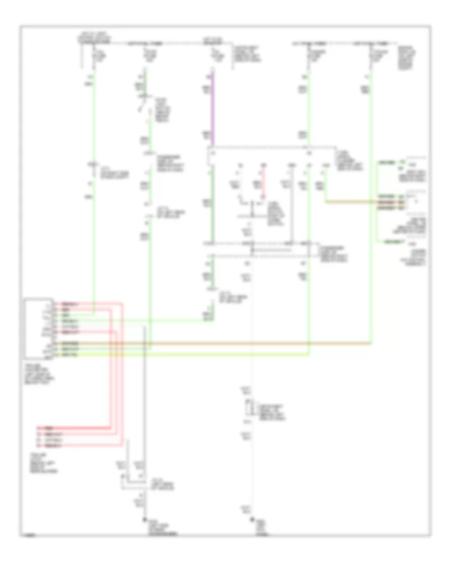
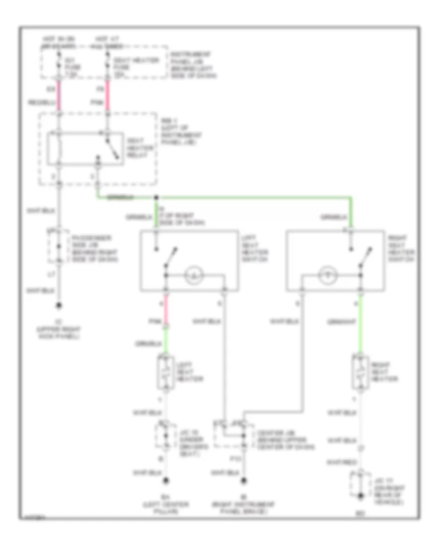
Heated Seats Wiring Diagram for Toyota Highlander Limited 2001
List of elements for Heated Seats Wiring Diagram for Toyota Highlander Limited 2001:
- Ba (left center pillar)
- Center j/b (behind upper center of dash)
- F13
- Hot at all times
- Hot in on or start)
- Ib (right instrument panel brace)
- Ic (upper right kick panel)
- Ig1 fuse 7.5a
- Instrument panel j/b (behind left side of dash)
- J/c 11 (on right rear of vehicle)
- J/c 15 (under driver's seat)
- Left seat heater
- Lfft seat heater switch
- Passenger side j/b (behind right side of dash)
- Pnk
- R/b 1 (left of instrument panel j/b)
- Right seat heater
- Right seat heater switch
- Seat heater fuse 15a
- Seat heater relay
- Side of dash)
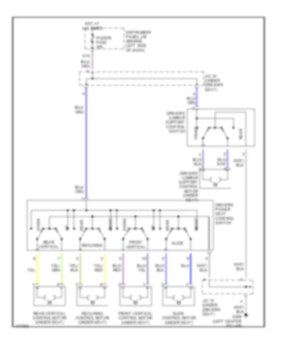
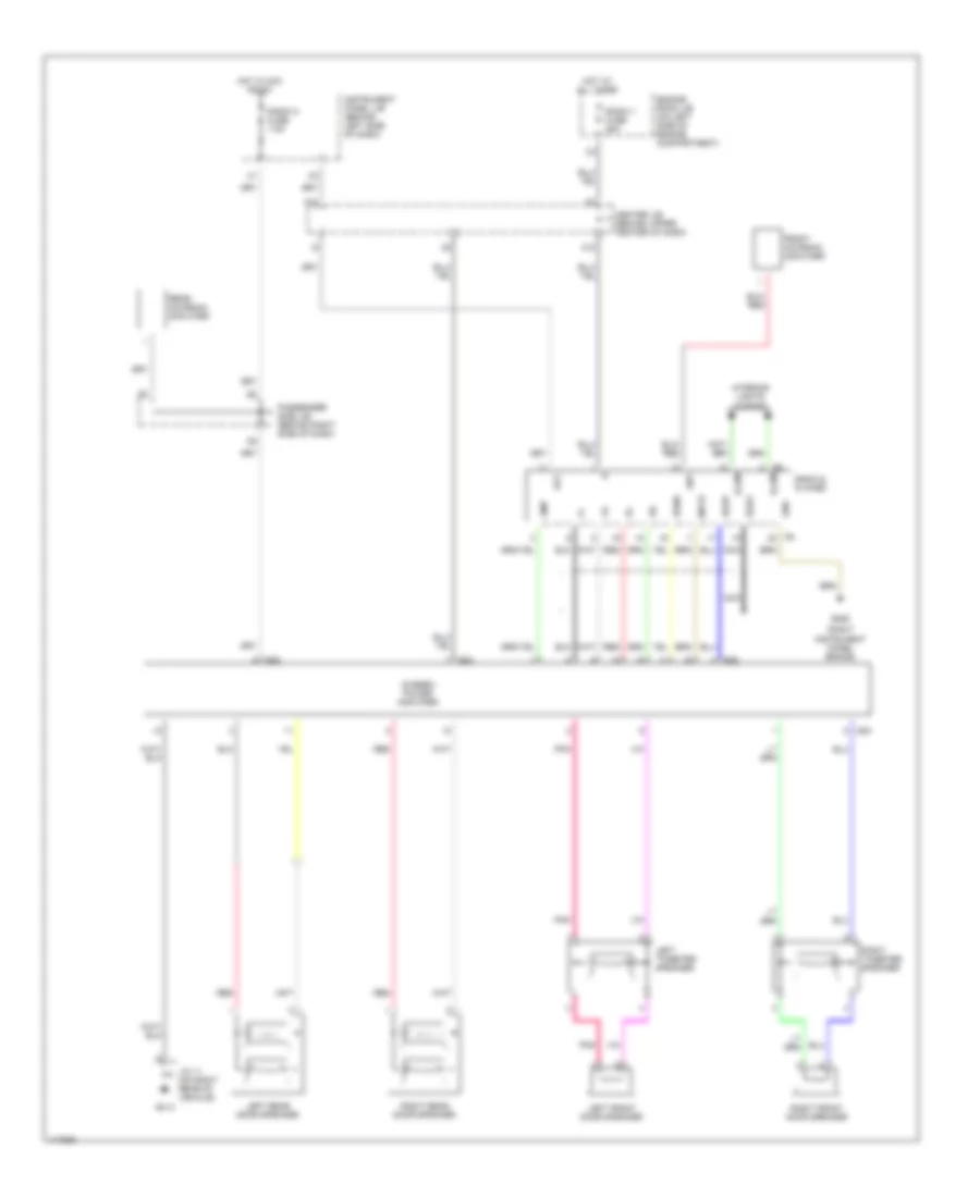
Power & Lumbar Seat Wiring Diagram for Toyota Highlander Limited 2001
List of elements for Power & Lumbar Seat Wiring Diagram for Toyota Highlander Limited 2001:
- D13
- Down
- Driver's lumbar support control motor (under seat)
- Driver's lumbar support control switch
- Driver's power seat control switch
- Front
- Front vertical
- Front vertical control motor (under seat)
- G308 (left center pillar)
- Hot at all times
- Instrument panel j/b (behind left side of dash)
- J/c 15 (under driver's seat)
- Power fuse 30a
- Rear
- Rear vertical
- Rear vertical control motor (under seat)
- Reclining
- Reclining control motor (under seat)
- Slide
- Slide control motor (under seat)
POWER TOP/SUNROOF
Power Top/Sunroof Wiring Diagrams for Toyota Highlander Limited 2001
List of elements for Power Top/Sunroof Wiring Diagrams for Toyota Highlander Limited 2001:
- (upper right kick panel)
- Cls
- Computer data lines system
- Ecu-ig fuse 15a
- G203
- Hot at all times
- Hot in on or start
- Instrument panel j/b (behind left side of dash)
- Ls1
- Ls2
- Mpx1
- Opn
- Pnk
- S/roof fuse 20a
- Slide close/ tilt up
- Slide open/ tilt down
- Sliding roof control ecu (on center front of roof)
- Sliding roof control switch
POWER WINDOWS
Power Window Wiring Diagram for Toyota Highlander Limited 2001
List of elements for Power Window Wiring Diagram for Toyota Highlander Limited 2001:
- A10
- Acc
- B10
- B11
- B12
- Bdr
- Becu
- Body ecu (behind right side of dash)
- Center j/b (behind upper center of dash)
- Computer data lines system
- Cpub
- D fr door fuse 20a
- D rr door fuse 20a
- D12
- Ecu-b fuse 7.5a
- Engine room j/b (left side of engine compt)
- F13
- G10
- G203 (upper right kick panel)
- G206 (right instrument panel brace)
- G305 (right center pillar)
- G308 (left center pillar)
- Gnd
- Gnd1
- Gnd2
- H11
- Hot at all times
- Hot in on or acc
- Hot in on or start
- I10
- I11
- Ig1 fuse 7.5a
- Instrument panel j/b (behind left side of dash)
- K10
- Kul
- L10
- Left front door key lock & unlock switch
- Left front power window motor
- Left rear power window motor
- Left rear power window switch
- Limit switch
- Lmt
- Lswe
- Mpx1
- Mpx2
- P fr door fuse 25a
- P rr door fuse 20a
- Passenger side j/b (behind right side of dash)
- Pct
- Pls
- Pnk
- Power window master switch with ecu
- Pulse sensor
- Pws
- Radio 2 fuse 7.5a
- Red
- Right front power window motor
- Right front power window switch
- Right rear power window motor
- Right rear power window switch
- Rld
- Rlu
- Rrd
- Rru
- Sgnd
- Sig
RADIO
Radio Wiring Diagrams, 6 Speaker System for Toyota Highlander Limited 2001
List of elements for Radio Wiring Diagrams, 6 Speaker System for Toyota Highlander Limited 2001:
- A13
- Engine room j/b (left side of engine compt)
- G206 (right instrument panel brace)
- Hot at all times
- Hot in acc or run
- Instrument panel j/b (behind left end of dash)
- Interior lights system
- Left front door speaker
- Left rear door speaker
- Left tweeter speaker
- Pnk
- Rad 1 fuse 25a
- Rad 2 fuse 7.5a
- Radio & player
- Red
- Right front door speaker
- Right rear door speaker
- Right tweeter speaker
- Sub j/b 3 (behind right side of instrument cluster)
Radio Wiring Diagrams, 8 Speaker System for Toyota Highlander Limited 2001
List of elements for Radio Wiring Diagrams, 8 Speaker System for Toyota Highlander Limited 2001:
- (right instrument panel brace)
- A13
- Acc
- Amp
- Ant
- Beep
- Center j/b (behind upper center of dash)
- Engine room j/b (on left side of engine compartment)
- Front antenna amplifier
- G206
- G413
- Gnd
- Hot at all times
- Hot in acc or on
- Illum
- Instrument panel j/b (behind left side of dash)
- Interior lights system
- J/c 11 (on right rear of vehicle)
- K10
- Left front door speaker
- Left rear door speaker
- Left tweeter speaker
- Mute
- Nca
- Passenger side j/b (behind right side of dash)
- Pnk
- Radio & player
- Radio 1 fuse 25a
- Radio 2 fuse 7.5a
- Rear antenna amplifier
- Red
- Right front door speaker
- Right rear door speaker
- Right tweeter speaker
- S22
- S23
- Sgd3
- Sgnd
- Stereo power amplifier
SHIFT INTERLOCKS
Shift Interlock Wiring Diagram for Toyota Highlander Limited 2001
List of elements for Shift Interlock Wiring Diagram for Toyota Highlander Limited 2001:
- Acc
- Center j/b (behind upper center of dash)
- Ecu-ig fuse 15a
- F13
- G203 (upper right kick panel)
- G206 (right instrument panel brace)
- Hot at all times
- Hot in acc or on
- Hot in on or start
- Instrument panel j/b (behind left side of dash)
- Key interlock solenoid
- Kls+
- Nca
- Passenger side j/b (behind right side of dash)
- Radio 2 fuse 7.5a
- Shift lock control switch
- Shift lock ecu (at base of shift lever)
- Shift lock solenoid
- Sls+
- Sls-
- Stop fuse 20a
- Stoplight switch (above brake pedal)
- Stp
STARTING/CHARGING
Charging Wiring Diagram for Toyota Highlander Limited 2001
List of elements for Charging Wiring Diagram for Toyota Highlander Limited 2001:
- 2.4l
- 3.0l
- Alt fuse 140a
- Alt s fuse 7.5a
- Battery
- Battery ground
- C11
- Center j/b (behind upper center of dash)
- Charge warning light
- Comb- ination meter
- Computer data lines
- Ecu-ig fuse 15a
- Engine control module (behind right side of dash)
- Engine room j/b (left side of engine compt)
- Fusible link block (engine compartment right side of firewall)
- Generator
- Heater fuse 15a
- Hot in on or start
- Instrument panel j/b (behind left side of dash)
- K13
- Main fusible link 3.0w
- Nca
- Passenger side j/b (behind right side of dash)
Starting Wiring Diagram for Toyota Highlander Limited 2001
List of elements for Starting Wiring Diagram for Toyota Highlander Limited 2001:
- (2.4l)
- (3.0l)
- (left side of engine compt)
- 2.4l
- 3.0l
- Acc
- Am2 fuse 30a
- Battery
- Battery ground
- Engine control module (behind right side of dash)
- Engine room r/b (left side of engine compt)
- Fusible link block (left side of engine compt)
- G112 (left side of cylinder block)
- G121 (right side of surge tank)
- Ignition switch
- Main fusible link 3.0w
- Nca
- Nsw
- Off
- P/n
- Park/ neutral position switch (left side of transmission)
- Sta
- Start
- Starter
- Starter fuse 7.5a
- Starter relay
SUPPLEMENTAL RESTRAINTS
Supplemental Restraint Wiring Diagram for Toyota Highlander Limited 2001
List of elements for Supplemental Restraint Wiring Diagram for Toyota Highlander Limited 2001:
- (front passenger air bag assembly) air bag squib
- (front seat right wire) b3
- (left center pillar) g308
- (left kick panel) g200
- (steering wheel pad) air bag squib
- (under left side of dash) (partial) data link connector (dlc) 3
- +sl
- +sr
- -sl
- -sr
- 4 cyl
- 6 cyl
- A12
- A16
- A17
- A18
- Air bag
- Air bag sensor assembly (below shifter console)
- B11
- Body ecu (behind right side of dash)
- C11
- Center j/b (behind upper center of dash)
- Combination meter
- D14
- Dbkl
- E11
- Engine control module (behind right side of dash)
- Esl
- Esr
- F/ps
- G413
- Gsw2
- Heater fuse 15a
- Hot in on or start
- Ig1
- Ig2
- Ign fuse 7.5a
- Instrument panel j/b (behind left side of dash)
- J/c 11 (on right rear of vehicle)
- J/c 15 (under driver's seat)
- J/c 6 (left side of dash, behind combination meter)
- J/c 9 (behind left kick panel)
- K13
- L10
- Lbe+
- Left air bag sensor (on left front of vehicle)
- Left buckle switch
- Left pretensioner (at base of left "b" pillar)
- Left side air bag sensor (w/side air bag) (at base of left "b" pillar)
- Left side air bag squib (w/side air bag)
- Passenger side j/b (behind right side of dash)
- Pbkl
- Pl+
- Pl-
- Pnk
- Pr+
- Pr-
- Rbe+
- Right air bag sensor (on right front of vehicle)
- Right buckle switch
- Right pretensioner (at base of right "c" pillar)
- Right side air bag sensor (w/side air bag) (at base of right "b" pillar)
- Right side air bag squib (w/side air bag)
- Seat belt warning occupation detection sensor (under passenger's seat)
- Sfl+
- Sfl-
- Sfr+
- Sfr-
- Sil
- Solid state
- Srs-ig fuse 15a
- Ssl+
- Ssl-
- Ssr+
- Ssr-
- Vupl
- Vupr
TRANSMISSION
2.4L
2.4L, A/T Wiring Diagram (1 of 2) for Toyota Highlander Limited 2001
List of elements for 2.4L, A/T Wiring Diagram (1 of 2) for Toyota Highlander Limited 2001:
- (dash harn, right side of dash) i6
- (engine harn, rear of engine) e9
- (left side of engine compt) counter gear speed sensor
- (on side of transmission) turbine speed sensor
- Batt
- Cruise control ecu (behind left side of dash)
- Driver side j/b (behind left side of dash)
- Dsl
- E01
- E02
- E03
- E04
- E05
- Ect
- Ee (on intake side of cylinder block)
- Ef (left side of cylinder block)
- Efi fuse 20a
- Efi relay
- Electronically controlled transmission solenoid (on left side of transaxle)
- Engine control module (behind right side of dash)
- Engine coolant temperature sensor (left rear of engine)
- Engine room j/b (on left side of engine compt)
- Hot at all times
- Hot in on or accy
- Ign fuse 7.5a
- Igsw
- Instrument panel j/b (behind left side of dash)
- J/c 2 (under left headlight)
- J/c 7 (behind right side of dash)
- M12
- Mpx1
- Mpx2
- Mrel
- Nc+
- Nc-
- Nt+
- Nt-
- Od1
- Odlp
- Odms
- Pnk
- Red
- Sl1+
- Sl1-
- Sl2+
- Sl2-
- Slt+
- Slt-
- Spd
- Stop fuse 20a
- Stop- light switch (above brake pedal)
- Stp
- Tho
- Throttle position sensor (on side of throttle body)
- Thw
- Vta1
2.4L, A/T Wiring Diagram (2 of 2) for Toyota Highlander Limited 2001
List of elements for 2.4L, A/T Wiring Diagram (2 of 2) for Toyota Highlander Limited 2001:
- (engine harn, behind right side of dash) i6
- A/c control assembly
- A/t indicator switch (on left side of transmission)
- A10
- A11
- B10
- Body ecu (behind right side of dash)
- C11
- C12
- Center j/b (behind upper center of dash)
- Combination meter
- Electronically controlled transmission pattern sensor
- F13
- Hot in on or start
- Ib (right dash brace)
- Ign 1 fuse 7.5a
- Instrument panel j/b (behind left side of dash)
- J/c 6 (behind left side of dash)
- Mpx+
- Mpx-
- Mpx1
- Mpx2
- O/d main switch
- O/d off
- Passenger side j/b (behind right side of dash)
- Power window master switch w/ ecu
- S10
- S11
- Skid control ecu (above instrument panel j/b)
- Snow
- W/ vsc
- W/o vsc
3.0L
3.0L, A/T Wiring Diagram (1 of 2) for Toyota Highlander Limited 2001
List of elements for 3.0L, A/T Wiring Diagram (1 of 2) for Toyota Highlander Limited 2001:
- (engine harn, behind right side of dash) i6
- (left side of engine compt) counter gear speed sensor
- (on side of transmission) turbine speed sensor
- Batt
- Cruise control ecu (behind left side of dash)
- Driver side j/b (behind left side of dash)
- Dsl
- E01
- E02
- E03
- E04
- E05
- E7 (engine harn, left side of engine)
- Ec (right side of surge tank)
- Ect
- Ed (rear side of surge tank)
- Efi fuse 20a
- Efi relay
- Electronically controlled transmission solenoid (on left side of transaxle)
- Engine control module (behind right side of dash)
- Engine coolant temperature sensor (front center of engine)
- Engine room j/b (on left side of engine compt)
- Hot at all times
- Hot in on or accy
- Ign fuse 7.5a
- Igsw
- Instrument panel j/b (behind left side of dash)
- J/c 2 (under left headlight)
- J/c 7 (behind right side of dash)
- M12
- Mpx1
- Mpx2
- Mrel
- Nc+
- Nc-
- Nt+
- Nt-
- Od1
- Odlp
- Odms
- Pnk
- Red
- Sl1+
- Sl1-
- Sl2+
- Sl2-
- Slt+
- Slt-
- Spd
- Stop fuse 20a
- Stop- light switch (above brake pedal)
- Stp
- Tho
- Throttle position sensor (on side of throttle body)
- Thw
- Vta1
3.0L, A/T Wiring Diagram (2 of 2) for Toyota Highlander Limited 2001
List of elements for 3.0L, A/T Wiring Diagram (2 of 2) for Toyota Highlander Limited 2001:
- A/c control assembly
- A/t indicator switch (on left side of transmission)
- A10
- A11
- B10
- Body ecu (behind right side of dash)
- C11
- C12
- Center j/b (behind upper center of dash)
- Combination meter
- Dash)
- Electronically controlled transmission pattern sensor
- F13
- Hot in on or start
- Ib (right dash brace)
- Ign 1 fuse 7.5a
- Instrument panel j/b (behind left side of dash)
- J/c 8 (behind right side of d
- Mpx+
- Mpx-
- Mpx1
- Mpx2
- O/d main switch
- O/d off
- Passenger side j/b (behind right side of dash)
- Power window master switch w/ ecu
- S10
- S11
- Skid control ecu (above instrument panel j/b)
- Snow
- W/ vsc
- W/o vsc
WARNING SYSTEMS
Warning System Wiring Diagrams for Toyota Highlander Limited 2001
List of elements for Warning System Wiring Diagrams for Toyota Highlander Limited 2001:
- (2.4l) (3.0l)
- (3.0l) (2.4l)
- (right instrument panel brace)
- A/c control assembly
- A10
- A11
- Acc
- B10
- B11
- B12
- Becu
- Body ecu (behind right side of dash)
- Buzzer
- C11
- C12
- Center j/b (behind upper center of dash)
- Combination meter
- D11
- Dbkl
- Dcty
- Dome fuse 10a
- E5 e5
- Ecu-b fuse 7.5a
- Engine control module (behind right side of dash)
- Engine room j/b (left side of eng compt)
- G10
- G203 (upper right kick panel)
- G206
- G308 (left center pillar)
- G413
- Heater fuse 15a
- Hot at all times
- Hot in accy or on
- Hot in on or start
- Ig1 fuse 7.5a
- Instrument panel j/b (behind left side of dash)
- J/c 11 (on right rear of vehicle)
- J/c 15 (under driver's seat)
- J/c 6 (behind instrument cluster)
- J/c 9 (behind left kick panel)
- K10
- K13
- Ksw
- Left buckle switch
- Left front door courtesy switch
- Mpx+
- Mpx-
- Mpx1
- Mpx2
- Passenger seat belt warning ind
- Passenger side j/b (behind right side of dash)
- Pkbl
- Power window master switch (w/ ecu)
- Radio 2 fuse 7.5a
- Right buckle switch
- Seat belt ind
- Seat belt warning occupant detection sensor (under passenger's seat)
- Unlock warning switch
WIPER/WASHER
Front Wiper/Washer Wiring Diagram for Toyota Highlander Limited 2001
List of elements for Front Wiper/Washer Wiring Diagram for Toyota Highlander Limited 2001:
- Combination switch
- D14
- Front washer switch
- Front wiper motor (on left rear of engine compt)
- Front wiper switch
- G200 (left kick panel)
- High
- Hot in on or start
- Instrument panel j/b (behind left side of dash)
- Int
- Int time
- Low
- Off
- Passenger side j/b (behind right side of dash)
- Red
- Solid state
- Washer fuse 20a
- Washer motor (on right front of engine compt)
- Wiper fuse 25a
Rear Wiper/Washer Wiring Diagram for Toyota Highlander Limited 2001
List of elements for Rear Wiper/Washer Wiring Diagram for Toyota Highlander Limited 2001:
- Combination switch
- D14
- G200 (left kick panel)
- Hot in on or start
- Instrument panel j/b (behind left side of dash)
- Int
- Off
- Passenger side j/b (behind right side of dash)
- Pnk
- Rear wiper & washer switch
- Rear wiper motor
- Rr wip fuse 15a
- Washer 1
- Washer 2
- Washer fuse 20a
- Washer motor (on right front of engine compt)

 Čeština
 Dansk
Dansk Deutsch
 Ελληνικά
 English
 English
 Español
 Français
 Français
 עברית
עברית Hrvatski
 Magyar
 Italiano
 日本語
日本語 한국어
한국어 Nederlands
 Polski
 Português
 Português
 Română
 Русский
 Slovenčina
 Slovenščina
 Svenska
 Türkçe
 中文 (中国)