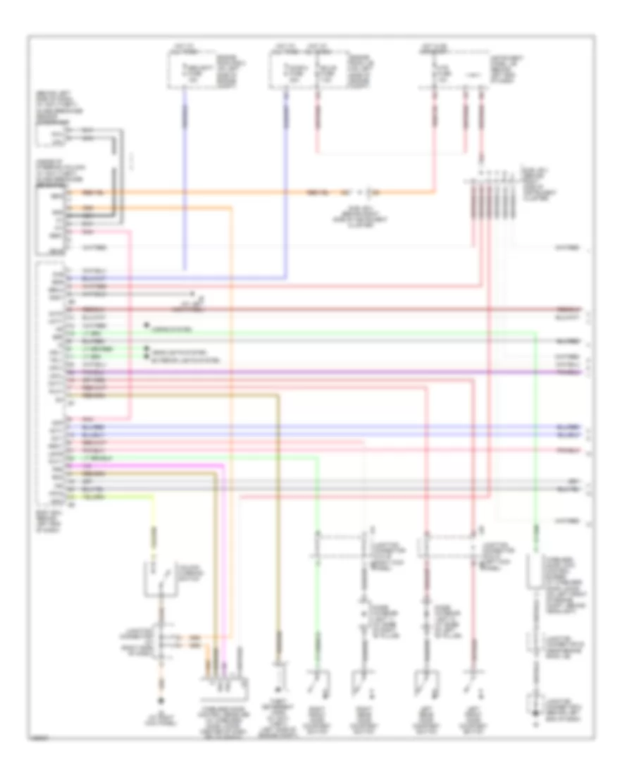
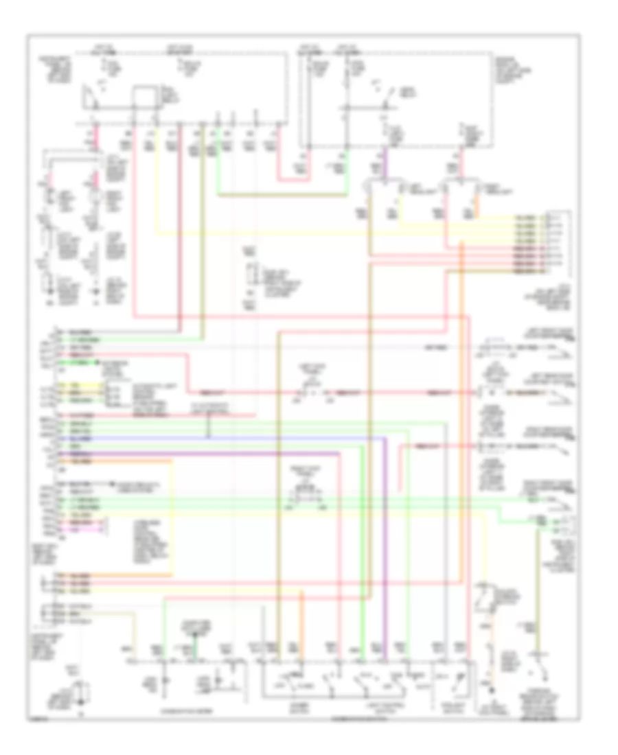
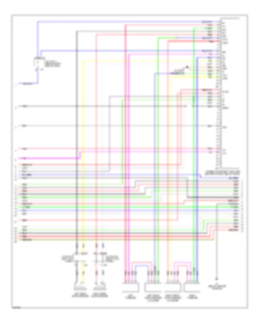
AIR CONDITIONING
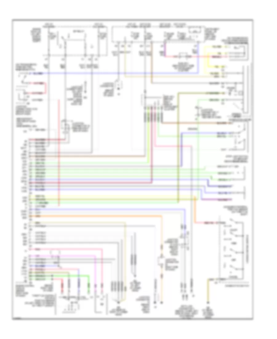
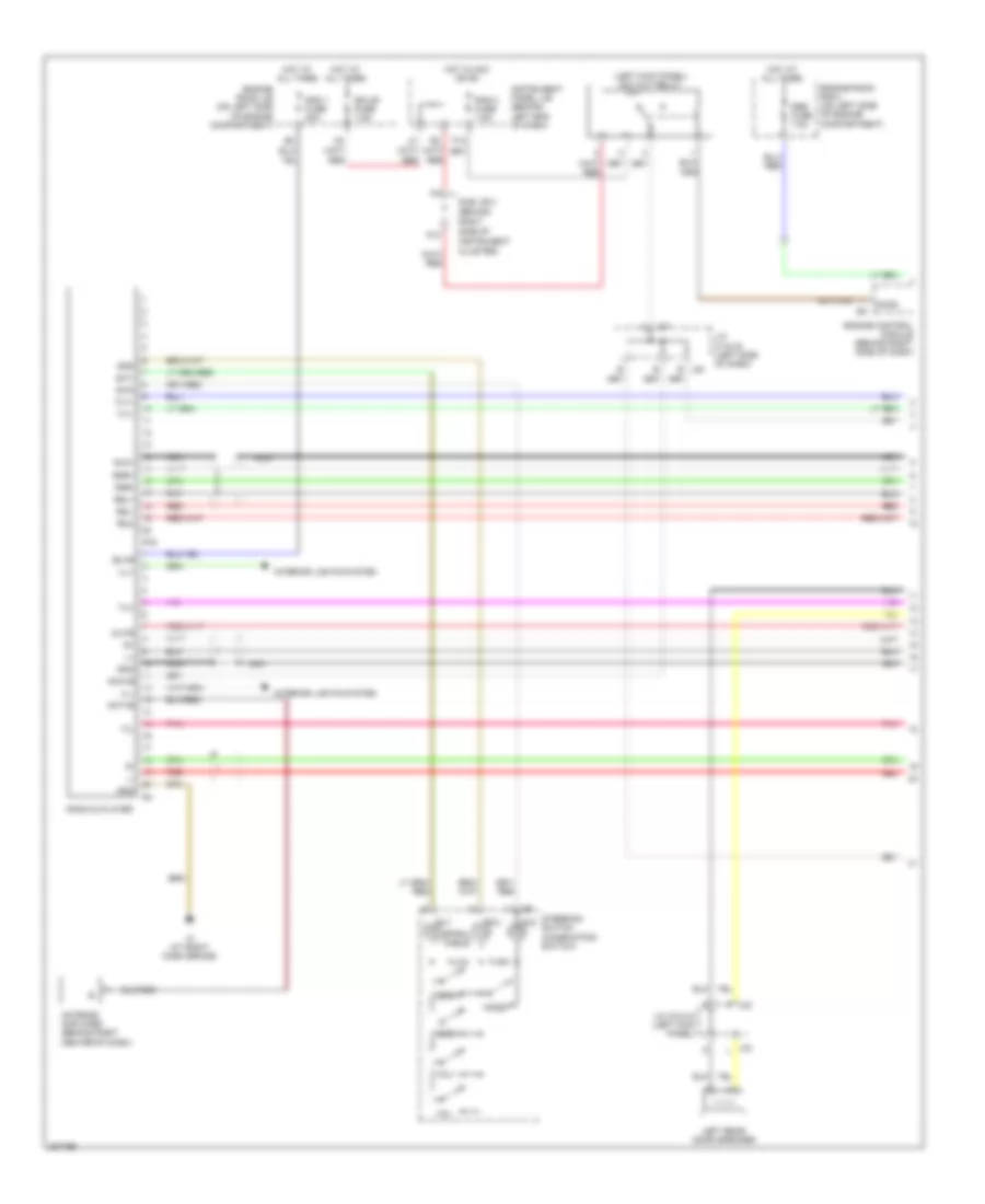
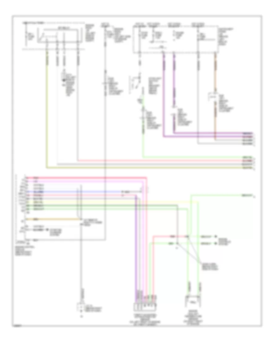
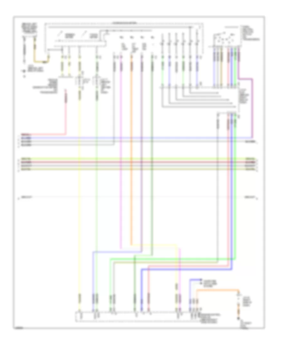
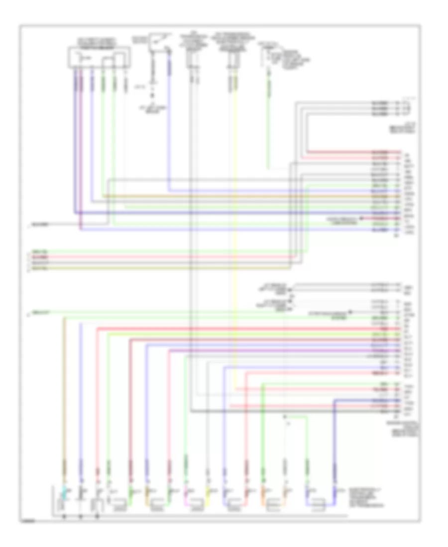
Automatic A/C Wiring Diagram (1 of 3) for Toyota Sequoia SR5 2006
 https://portal-diagnostov.com/license.html
Automotive Electricians Portal FZCO
Automotive Electricians Portal FZCO
https://portal-diagnostov.com/license.html
https://portal-diagnostov.com/license.html
Automotive Electricians Portal FZCO
Automotive Electricians Portal FZCO
List of elements for Automatic A/C Wiring Diagram (1 of 3) for Toyota Sequoia SR5 2006:
- (behind right side of instrument cluster) sub j/b 4
- (on left side of engine compt, near engine room j/b) junction connector 3
- A/c
- A/c evaporator temperature sensor (front) (behind right center of dash)
- A/c room temperature sensor (front) (behind lower left center of dash)
- A/c solar sensor (on top left side of dash)
- A16
- Acc
- Aif
- Air
- Air inlet control servo motor (behind right side of dash)
- Air mix control servo motor (front) (behind lower right side of dash)
- Air vent mode control servo motor (front) (behind lower left side of dash)
- Amc
- Amh
- B/l
- Blw
- Cig fuse 15a
- Computer data lines system
- Def
- Dome fuse 10a
- E20
- Engine room j/b (on left side of engine compt)
- Engine room r/b 2 (on left side of engine compt)
- Face
- Fdef
- Foot
- Frs
- Gnd
- Hot at all times
- Hot in acc or on
- Hot in on or start
- Htr fuse 10a
- I19
- I20
- Ig (at right kick panel)
- Ig+
- Ill+
- Ill-
- Instrument panel j/b (behind left end of dash)
- Integration control & panel (behind center of dash)
- Interior lights system
- Junction connector 15
- Junction connector 43 (right side of dash)
- Lock
- Mcool
- Mg clt relay
- Mgc
- Mhot
- Mpx+
- Mpx-
- Pnk
- Psw
- Rec
- Red
- S5-ai
- S5-am
- S5-tr
- Sg-tam
- Sg-te
- Sg-tp
- Sg-tpi
- Sg-tr
- Sub j/b 3 (behind right side of instrument cluster)
- Tam
- Tp1
- W/ rear
- W/ rear a/c
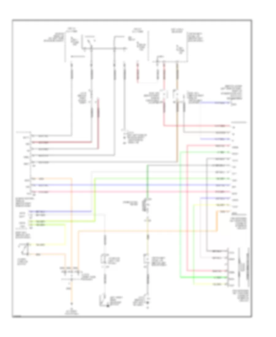
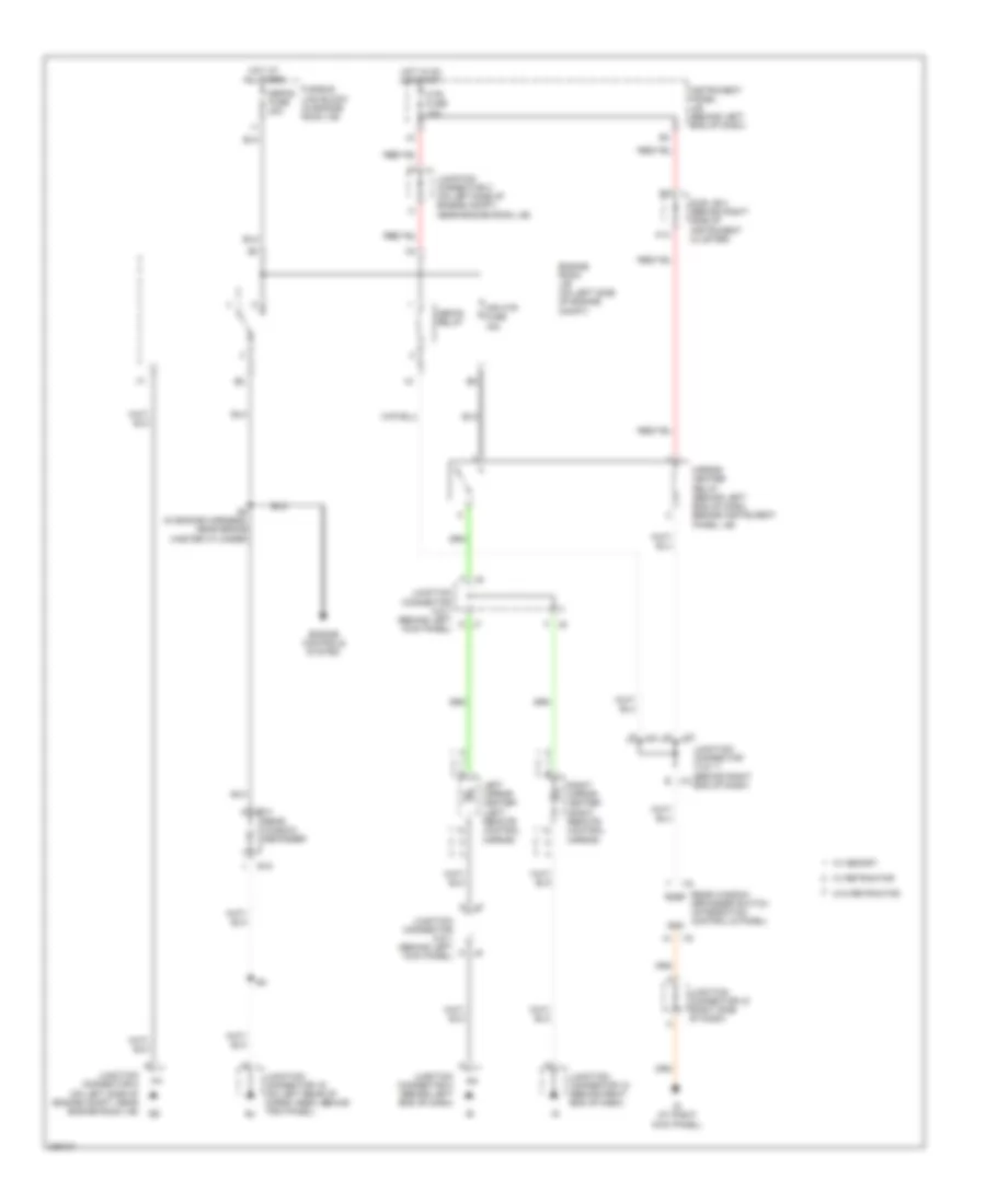
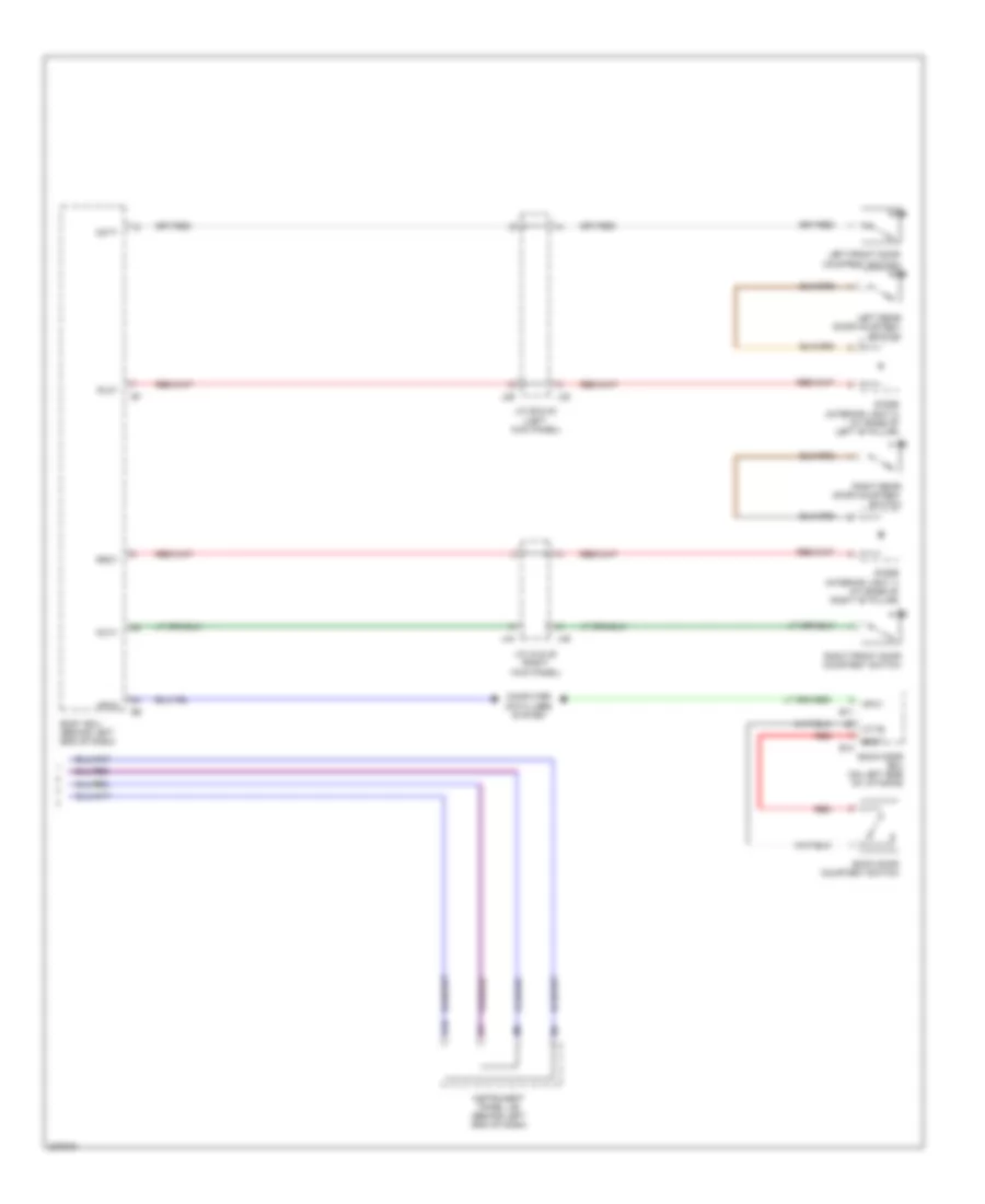
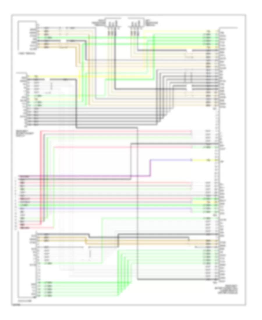
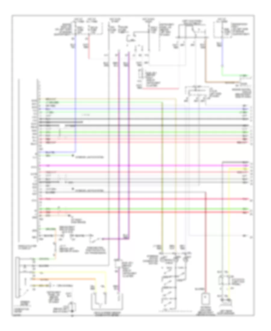
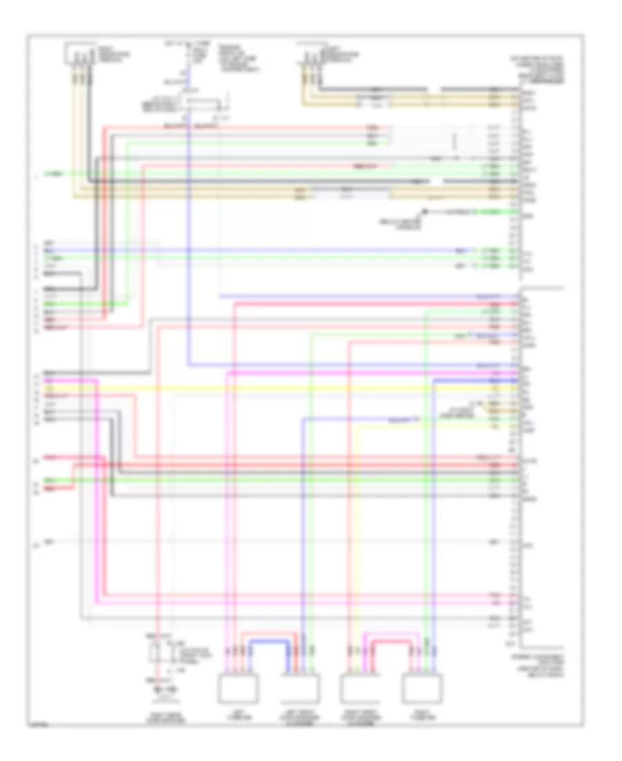
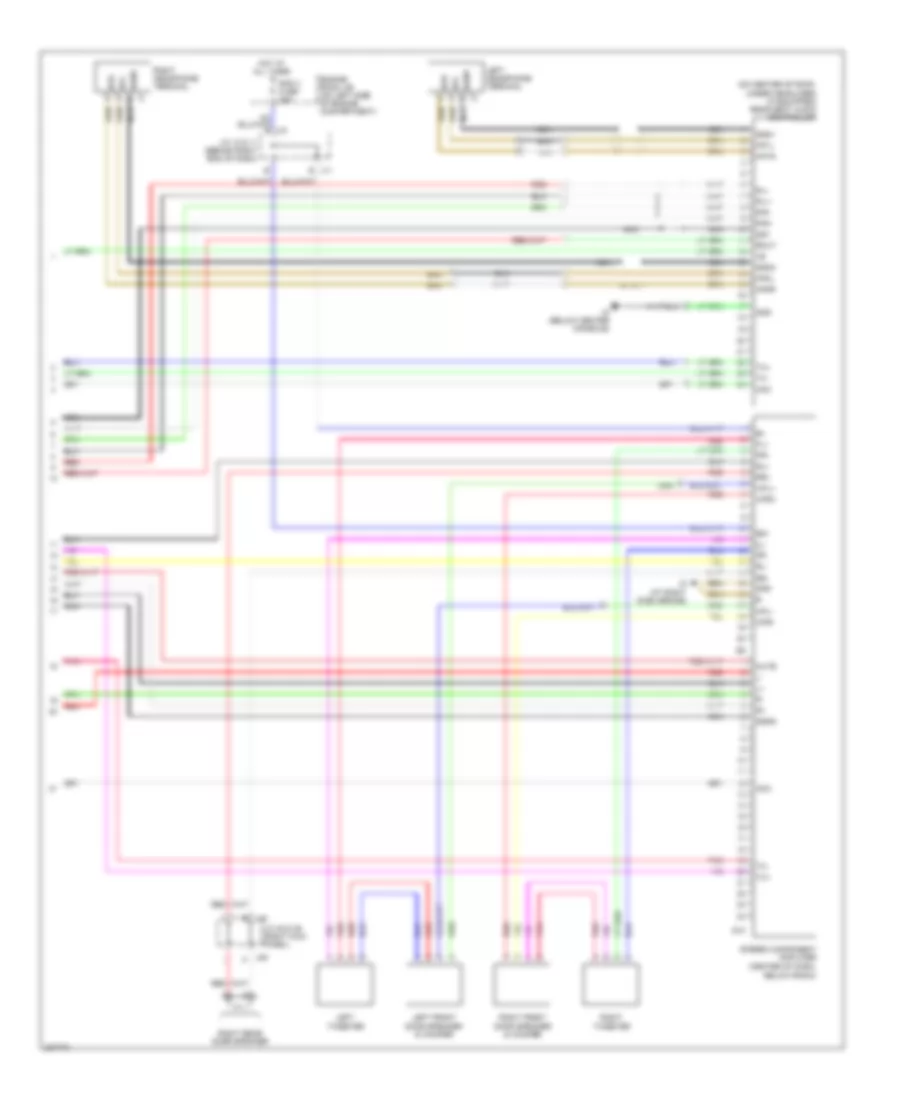
Automatic A/C Wiring Diagram (2 of 3) for Toyota Sequoia SR5 2006
List of elements for Automatic A/C Wiring Diagram (2 of 3) for Toyota Sequoia SR5 2006:
- (w/ rear a/c) rr heater relay
- A/c ambient temperature sensor (on left front of engine compt)
- A/c condenser fan motor (on center front of engine compt)
- A/c magnetic clutch & lock sensor (on left front of engine compt)
- Blower motor (front) (behind lower right side of dash)
- Blower motor control
- Cds fan fuse 25a
- Cds fan relay
- Dual
- Engine room r/b 2 (on left side of engine compt)
- Engine room r/b 4 (on left side of engine compt)
- Fusible link block (in engine room j/b)
- Gnd
- Heater fuse 50a
- Heater relay
- Hot at all times
- I5 (in dash harness, behind right side of dash)
- J14
- J15
- J48
- J49
- Junction connector 1 (on right front of engine compt)
- Junction connector 14 & 15
- Junction connector 18 (behind right end of dash)
- Junction connector 48 & 49 (right kick panel)
- Junction connector 50 (left side of engine compartment)
- Noise filter (in line)
- Pressure switch (on right front of engine compt)
- Red
- Rr heater fuse 30a
- Single
- W/ rear a/c
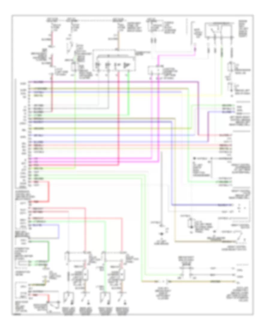
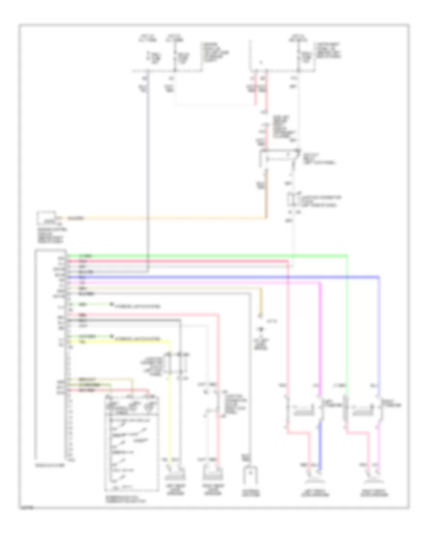
Automatic A/C Wiring Diagram (3 of 3) for Toyota Sequoia SR5 2006
List of elements for Automatic A/C Wiring Diagram (3 of 3) for Toyota Sequoia SR5 2006:
- (behind right side of dash)
- (behind right side of instrument cluster) sub j/b 3
- (in body harness, in right rear quarter panel)
- (in dash harness, behind right side of dash)
- (in dash harness, behind right side of dash) i5
- (on right front of engine)
- (on right rear of vehicle)
- (w/ rear a/c)
- (w/ rear a/c) blower motor (rear)
- 2lo
- A/c control (rear heater control panel) (w/ rear a/c)
- A/c evaporator temperature sensor (rear) (w/ rear a/c) (on right rear of vehicle)
- A/c power transistor (w/ rear a/c) (on right rear of vehicle)
- A/c room temperature sensor (rear) (w/ rear a/c) (front of left quarter panel)
- A/c water valve (rear) (w/ rear a/c) (on right rear of vehicle)
- A15
- Ac1
- Act
- Air vent mode control servo motor (rear)
- Bp (at right side of rear quarter panel)
- Clk
- Dpd
- Engine control module
- Engine control system
- Engine coolant temperature sensor
- Gauge fuse 15a
- Gnd
- Hot in on or start
- Hrhr
- I21
- I22
- Ig (at right kick panel)
- Ign
- Ill+
- Ill-
- Instrument panel j/b (behind left end of dash)
- Integration control & panel (behind center of dash)
- Interior lights system
- J31
- J32
- Junction connector
- Junction connector 14
- Junction connector 31 & 32 (left kick panel)
- Junction connector 43 (right side of dash)
- Junction connector 57
- Lms
- Mcool
- Mhot
- Nca
- Noise filter (in line)
- Red
- Rramc
- Rramh
- Rrb/l
- Rrb/l2
- Rrblw
- Rrclk
- Rrdpd
- Rrface
- Rrface2
- Rrfoot
- Rrs5
- Rrsg
- Rrstx
- Rrswd
- Rrte
- Rrtp
- Rrtr
- Rrvm
- Sgrrtr
- Stx
- Swd
- Tach
- Thw
- Thwo
- W/ rear a/c
ANTI-LOCK BRAKES
Anti-lock Brakes Wiring Diagram (1 of 2) for Toyota Sequoia SR5 2006
List of elements for Anti-lock Brakes Wiring Diagram (1 of 2) for Toyota Sequoia SR5 2006:
- (near engine room j/b)
- (on brake master cylinder)
- +bm
- +bo
- +bs
- Abs fuse 60a
- Active brake booster (on left rear of engine compartment)
- Bst
- Bstp
- Bsw
- Canh
- Canl
- D/g
- Data link connector (dlc) 3 (behind lower left side of dash, right of steering column)
- E3 (in engine harness, near brake master cylinder)
- Fl+
- Fl-
- Fr+
- Fr-
- Fusible link block (in engine room j/b)
- Gnd1
- Gnd2
- Gyaw
- Hot at all times
- Ig1
- Instrument panel j/b (behind left end of dash)
- Junction connector 28
- Junction connector 8 (behind left end of dash)
- K12
- Left front abs speed sensor (on left front wheel)
- Left rear abs speed sensor (on left rear wheel)
- Master cylinder pressure sensor 1
- Master cylinder pressure sensor 2
- Nca
- Pedal stroke speed sensor
- Pim
- Pmc
- Pmc2
- Pnk
- Psnc
- Psno
- Red
- Right front abs speed sensor (on right front wheel)
- Right rear abs speed sensor (on right rear wheel)
- Rl+
- Rl-
- Rr+
- Rr-
- Sil
- Skid control ecu (w/actuator) (on right rear of engine compartment)
- Ss1
- Ss2
- Stop fuse 15a
- Stoplight switch (on bracket above brake pedal)
- Stp
- Sts
- Sub j/b 3 (behind right side of inst- rument cluster)
- Sub j/b 4 (behind right side of inst- rument cluster)
- Sub j/b 4 (behind right side of instrument cluster)
- Vcm
- Vcm2
- Vcp
- Vscw
- Vys
Anti-lock Brakes Wiring Diagram (2 of 2) for Toyota Sequoia SR5 2006
List of elements for Anti-lock Brakes Wiring Diagram (2 of 2) for Toyota Sequoia SR5 2006:
- of dash) junction connector 37 & 38
- (2wd) trac off ind
- (4wd) vsc off ind
- (behind left end of dash)
- (behind right end of dash)
- (left side
- 4wd
- 4wd control ecu (behind right center of dash)
- A17
- A18
- Abs ind
- Bat
- Brake fluid level warning switch (on brake fluid reservoir)
- Brake ind
- Brake inhibit relay (behind left center of dash)
- Brl
- Canh
- Canl
- Combination meter
- Cpu
- Csw
- Ecu-ig fuse 10a
- End of dash) j55
- Eng+
- Eng-
- Engine control module (behind right side of dash)
- Ess
- Exi2
- Exterior lights system
- Gauge fuse 15a
- Gnd
- H11
- Hot in acc or on
- Hot in on or start
- I19
- I22
- I3 (in dash harness, under left rear of center console) gyaw
- Ig (at right kick panel)
- Ig1
- Ign1 fuse 10a
- Im (below center console)
- Ind
- Ind2
- Instrument panel j/b (behind left end of dash)
- Integration control & panel (4wd) (behind center of dash)
- Ipo
- J37
- J38 a
- J51
- J53
- J54
- J55
- J56
- Junction connector 43 (right side of dash)
- Junction connector (right side of dash)
- Junction connector 18 (behind right end of dash)
- Junction connector 51 & 52
- Junction connector 53, 54, 55 & 56 (behind right
- Lvl2
- Park/ neutral position switch (on transmission)
- Parking brake switch (behind left side of dash, on parking brake lever)
- Pkb2
- Rad 2 fuse 7.5a
- Red
- Slip ind
- Ss1+
- Ss1-
- Steering angle sensor (inside of steering column)
- Sub j/b 3 (behind right side of instrument cluster)
- Sub j/b 4 (behind right side of instrument cluster)
- Suspension control ecu (center of dash, below radio)
- Transfer shift actuator (on transfer case)
- Translate ecu (above right kick panel)
- Trig
- Vsc trac ind
- Vsc warning buzzer
- Vsc+
- Vsc-
- Vys
- Yaw rate sensor (below rear of center console)
- Yaw1
- Yaw2
ANTI-THEFT
Forced Entry Wiring Diagram (1 of 3) for Toyota Sequoia SR5 2006
List of elements for Forced Entry Wiring Diagram (1 of 3) for Toyota Sequoia SR5 2006:
- (behind left side of dash) (w/ anti-theft) glass breakage sensor microphone
- (inside of steering column) (w/ anti-theft) glass breakage sensor ecu
- Act+
- Act-
- Actd
- Bdr
- Becu
- Body ecu (behind left end of dash)
- Bzr
- Dcty
- Diode (interior light 1) (at base of right "b" pillar)
- Diode (interior light 2) (at base of left "b" pillar)
- Door 2 fuse 30a
- Dop
- Ecu-b fuse 7.5a
- Engine room j/b (on left side of engine compt)
- Engine room r/b 2 (on left side of engine compt)
- Exterior lights system
- Gb+b
- Gbig
- Gbs1
- Gnd
- Gnd1
- Hcty
- Headlights system
- Horns system
- Hot at all times
- Hot in on or start
- Hrly
- Htr fuse 10a
- Ie (at left kick panel)
- Ig (at right kick panel)
- Ind
- Instrument panel j/b (behind left end of dash)
- J29
- J44
- Junction connector (right side of dash)
- Junction connector 28 (near engine room j/b)
- Junction connector 29 & 30 (left kick j30 panel)
- Junction connector 44 & 45 (right kick j45 panel)
- Junction connector 8 (behind left end of dash)
- Ksw
- Left front door courtesy switch
- Left rear door courtesy switch
- Lswl
- Lswr
- Mi+
- Mi-
- Mic+
- Mic-
- Mpx1
- Mpx2
- Nca
- Pcty
- Pnk
- Prg
- Rda
- Right front door courtesy switch
- Right rear door courtesy switch
- Rlcy
- Rrcy
- S+b
- Security fuse 15a
- Sub j/b 3 (behind right side of instrument cluster)
- Sub j/b 4 (behind right side of instrument cluster)
- Theft deterrent horn (w/ anti- theft) (left side of engine compt)
- Trly
- Unlock warning switch
- Wireless door control receiver (w/ wireless door locks) (center of dash, below radio)
- Wireless door lock control buzzer (w/ wireless door locks) (on left front of engine compt, behind headlight)
Forced Entry Wiring Diagram (2 of 3) for Toyota Sequoia SR5 2006
List of elements for Forced Entry Wiring Diagram (2 of 3) for Toyota Sequoia SR5 2006:
- Bh (at left "b" pillar)
- Bk (at right "b" pillar)
- Combination meter
- Engine hood courtesy switch (on left center of radiator support)
- Instrument cluster system
- Instrument panel j/b (behind left end of dash)
- Integration control & panel (behind center of dash)
- J10
- J11
- J29
- J30
- J33
- J34
- J44
- J45
- Junction connector 1 (on right front of engine compt)
- Junction connector 10 & 11 (behind right end of dash)
- Junction connector 29 & 30 (left kick panel)
- Junction connector 33 & 34 (left kick panel)
- Junction connector 44 & 45 (right kick panel)
- Junction connector 8 (behind left end of dash)
- Left front door lock motor, door key lock/unlock switch & door unlock detection switch
- Left rear door lock motor & door unlock detection switch
- Mpx+
- Mpx-
- Right rear door lock motor & door unlock detection switch
- Security
Forced Entry Wiring Diagram (3 of 3) for Toyota Sequoia SR5 2006
List of elements for Forced Entry Wiring Diagram (3 of 3) for Toyota Sequoia SR5 2006:
- Act+
- Act-
- B10
- B11
- Back door courtesy switch
- Back door ecu (on left side of liftgate)
- Back door key lock & unlock switch
- Back door lock motor & back door unlock detection switch
- Bdcy
- Bdr
- Becu
- Bkl
- Bkul
- Cpub
- Ctye
- Driver door ecu (in left front door)
- Ecu-ig fuse 10a
- F17
- Front passenger door ecu (in right front door)
- G11
- G15
- Gnd
- Hot at all times
- Hot in run or start
- If (at left dash brace)
- Instrument panel j/b (behind left end of dash)
- J33
- J37
- J38
- Junction conn- ector 12
- Junction connector 19 (on left rear of cargo area, behind trim panel)
- Junction connector 22 (on left side of liftgate)
- Junction connector 33 & 34 (left kick j34 panel)
- Junction connector 37 & 38 (left side of dash)
- Junction connector 6 & 7 (behind left kick panel)
- Junction connector 8 (behind left end of dash)
- Keye
- Kul
- Lswb
- Lswd
- Lswe
- Lswp
- Mpx1
- Mpx2
- Pkl
- Pkul
- Pwr 1 fuse 25a
- Pwr 2 fuse 25a
- Pwr 5 fuse 30a
- Red
- Right front door lock motor, door key lock/unlock switch & door unlock detection switch
- Sig
- Sub j/b 3 (behind right side of instrument cluster)
- W/ memory
- W/o memory
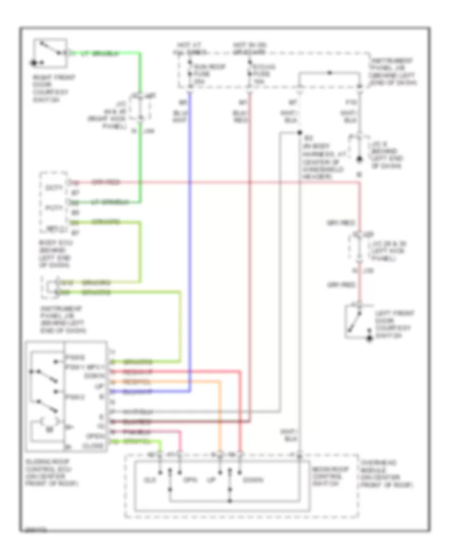
Immobilizer Wiring Diagram for Toyota Sequoia SR5 2006
List of elements for Immobilizer Wiring Diagram for Toyota Sequoia SR5 2006:
- (behind lower left side of dash, right of steering column) data link connector 3
- +b2
- Agnd
- Ant1
- Ant2
- Batt
- Body ecu (behind left end of dash)
- Code
- Combination meter
- Cty
- Dcty
- Dcy2
- E17
- Ecu-b fuse 7.5a
- Efi 1 fuse 20a
- Efi relay
- Efii
- Efio
- Engine control module (behind right side of dash)
- Engine room j/b (on left side of engine compt)
- Eom
- G j29
- Gnd
- Hot at all times
- Hot in run or start
- Ig (at right kick panel)
- Ign1 fuse 10a
- Igsw
- Imi
- Imo
- Ind
- Instrument panel j/b (behind left end of dash)
- J/c 16 (behind right end of dash)
- J/c 29 & 30 (left kick panel)
- J/c 43 (right side of dash)
- J/c 5 (on left side of engine compt, near engine room j/b)
- J/c 8 (behind left end of dash)
- Ksw
- Ksw2
- Left front door courtesy switch
- Mrel
- N j30
- Op3
- Rxck
- Security indicator
- Sub j/b 3 (behind right side of instrument cluster)
- Sub j/b 4 (behind right side of instrument cluster)
- Transponder key amplifier (inside of steering column)
- Transponder key coil
- Transponder key computer (inside of steering column)
- Txct
- Unlock warning switch
- Vc12
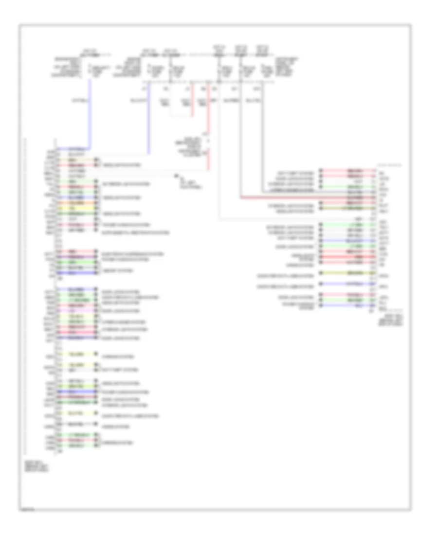
BODY CONTROL MODULES
Body Control Modules Wiring Diagram for Toyota Sequoia SR5 2006
List of elements for Body Control Modules Wiring Diagram for Toyota Sequoia SR5 2006:
- Acc
- Act+
- Act-
- Actd
- Acty
- Anti-theft system
- Bdn
- Bdr
- Becu
- Body ecu (behind left end of dash)
- Bup
- Bzr
- Cltb
- Clte
- Clts
- Computer data lines system
- Dcty
- Dcy2
- Dim
- Door 2 fuse 30a
- Door lock system
- Door locks system
- Dop
- Ecu-b fuse 7.5a
- Ecu-ig fuse 10a
- Electronic suspension system
- Engine room j/b (on left side of engine compartment)
- Engine room r/b 2 (on left side of engine compartment)
- Exterior lights system
- Ffog
- G10
- G11
- Gnd1
- Gsw
- H-on
- Hcty
- Head
- Headlights system
- Hind
- Horn
- Horns system
- Hot at all times
- Hot in acc or on
- Hot in on or start
- Hrly
- Ie (at left kick panel)
- Ile
- Ind
- Instrument panel j/b (behind left end of dash)
- Interior lights system
- Ksw
- Ksw2
- Lswl
- Lswr
- Memory system
- Mirb
- Mire
- Mirrors system
- Mirs
- Mpx1
- Mpx2
- Mpx3
- Obd2
- Pcty
- Pkb
- Pnk
- Power windows system
- Prg
- Pws
- Rad 2 fuse 7.5a
- Rda
- Red
- Rlcy
- Rld
- Rlu
- Rrcy
- Rrd
- Rru
- Rwc1
- Rwls
- Rww
- S+b
- Security fuse 15a
- Sub j/b 3 (behind right side of instrument cluster)
- Tail
- Trly
- Warning system
- Wig
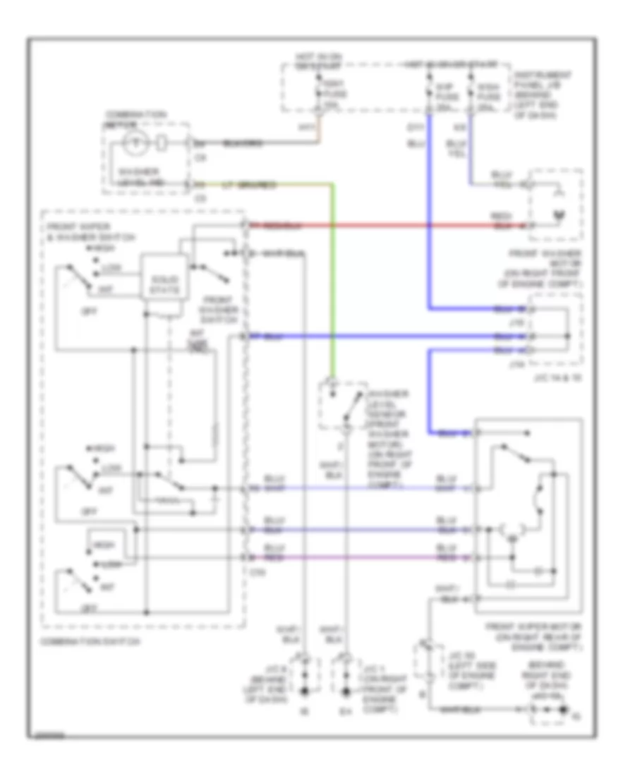
- Wiper/washer system
- Wsh fuse 25a
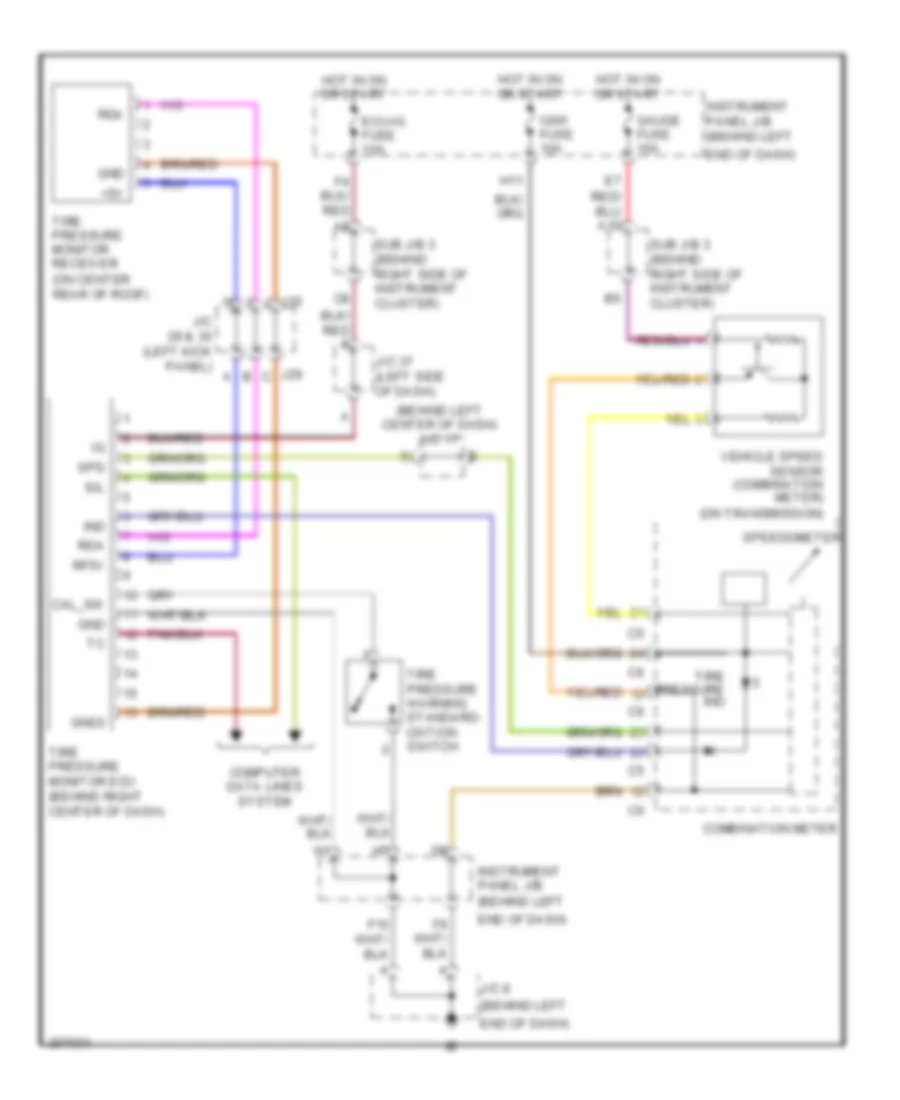
COMPUTER DATA LINES
Computer Data Lines Wiring Diagram for Toyota Sequoia SR5 2006
List of elements for Computer Data Lines Wiring Diagram for Toyota Sequoia SR5 2006:
- (behind left end of dash) instrument panel j/b
- (behind right center of dash) tire pressure monitor ecu
- (behind right side of instrument cluster) sub j/b 4
- (below front of center console) air bag sensor assembly
- (right kick panel) junction connector 48 & 49
- (under right front seat) occupant classification ecu
- A j34
- A10
- A20
- B10
- B11
- Back door ecu (on left side of liftgate)
- Bat
- Below radio)
- Body ecu (behind left end of dash)
- Canh
- Canl
- Combination meter
- D/g
- Data link connector (dlc) 3 (behind lower left side of dash, right of steering column)
- Dia
- Driver door ecu (in left front door)
- E14
- Eb (at rear of of right cylinder head)
- End of dash)
- Eng+
- Eng-
- Engine control module (behind right side of dash)
- F15
- Front passenger door ecu (in right front door)
- G j33
- G j34
- G12
- H j33
- Hot at all times
- I19
- Ig (at right kick panel)
- Instrument panel j/b (behind left end of dash)
- Integration control & panel (behind center of dash)
- J48
- J49
- J53
- J54
- J55
- J56
- Junction connector 33 & 34 (left kick panel)
- Junction connector 43 (right side of dash)
- Junction connector 53, 54, 55 & 56 (behind right
- Memory seat ecu & sw (side of left front seat)
- Mpx+
- Mpx-
- Mpx1
- Mpx2
- Mpx3
- Obd fuse 7.5a
- Obd2
- Of engine compt)
- Op3
- Red
- Sil
- Skid control ecu w/ actuator (on right rear
- Sliding roof control ecu (on center front of roof)
- Sub j/b 3 (behind right side of instrument cluster)
- Suspension control ecu (center of dash,
- Translate ecu (above right kick panel)
- Transponder key computer (inside of steering column)
- Vsc+
- Vsc-
- W/ memory
- W/o memory
CRUISE CONTROL
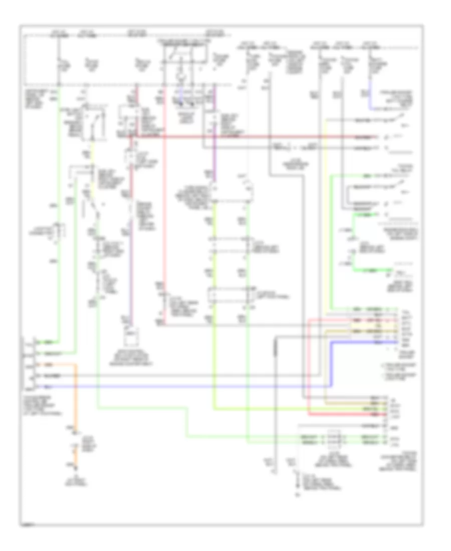
Cruise Control Wiring Diagram for Toyota Sequoia SR5 2006
List of elements for Cruise Control Wiring Diagram for Toyota Sequoia SR5 2006:
- (4wd) 4wd control ecu
- (at rear
- (behind right center of dash)
- (on transmission) park/neutral position switch
- (on transmission) vehicle speed sensor (combination meter)
- +b2
- +bm
- +res
- -set
- A15
- Accelerator pedal position sensor (on throttle body)
- Batt
- C/c
- Cancel
- Canh
- Canl
- Ccc
- Ccs
- Combination meter
- Combination switch
- Cruise control switch
- Cruise ind
- Data link connector 3 (behind lower left side of dash, right of steering column)
- E01
- E02
- E03
- E04
- E05
- E17
- Eb (at rear of right cylinder head)
- Ec (at rear of left cylinder head)
- Ecc
- Efi 1 fuse 20a
- Efi relay
- Engine control module (behind right side of dash)
- Engine room j/b (on left side of engine compt)
- Eom
- Ep1
- Epa
- Epa2
- Etcs fuse 10a
- Gauge fuse 15a
- Ge01
- H11
- Hot at all times
- Hot in acc or on
- Hot in on or start
- I4 (behind right side of dash)
- Ign1 fuse 10a
- Igsw
- Instrument panel j/b (behind left end of dash)
- Ipo
- J51
- J52
- J53
- J54
- Junction connector 8 (behind left end of dash)
- Junction connector (behind right end of dash)
- Junction connector (right side of dash)
- Junction connector 16 (behind right end of dash)
- Junction connector 17 (behind left center of dash)
- Junction connector 5 (on left side of engine compt, near engine room j/b)
- Junction connector 51 & 52 (behind right end of dash)
- Junction connector 51 & 54 (behind right end of dash)
- Me01
- Mrel
- Nca
- Of right cylinder head)
- On-off
- Pnk
- Rad 2 fuse 7.5a
- Red
- Spd
- Speedo- meter
- St1-
- Stop fuse 15a
- Stop light switch (on bracket above brake pedal)
- Stp
- Sub j/b 3 (behind right side of instrument cluster)
- Sub j/b 4 (behind right side of instrument cluster)
- Throttle control motor & position sensor (on left front of engine, on throttle body)
- Vcp2
- Vcpa
- Vpa
- Vpa2
- Vta1
- Vta2
DEFOGGERS
Defoggers Wiring Diagram for Toyota Sequoia SR5 2006
List of elements for Defoggers Wiring Diagram for Toyota Sequoia SR5 2006:
- A13
- Defog fuse 40a
- Defog relay
- E4 (in engine harness. near brake master cylinder)
- Engine controls system
- Engine room j/b (on left side of engine compt)
- Fusible link block (in engine room j/b)
- Gnd
- Hot at all times
- Hot in on or start
- Htr fuse 10a
- I19
- Ig (at right kick panel)
- Instrument panel j/b (behind left end of dash)
- J10
- J11
- Junction connector 10 & 11 (behind right j10 end of dash)
- Junction connector 18 (behind right end of dash)
- Junction connector 19 (on left rear of cargo area, behind trim panel)
- Junction connector 3 (on left side of engine compt, near engine room j/b)
- Junction connector 43 (right side of dash)
- Junction connector 5 (on left side of engine compt, near engine room j/b)
- Junction connector 6 & 7 (behind left kick panel)
- Junction connector 8 (behind left end of dash)
- Left mirror heater (left remote control mirror)
- Mir htr fuse 15a
- Mirror heater relay (behind left end of dash, beside instrument panel j/b)
- R14
- R15
- Rdef
- Rear window defogger
- Rear window defogger switch (integration control & panel)
- Right mirror heater (right remote control mirror)
- Sub j/b 4 (behind right side of instrument cluster)
- W/ memory
- W/ retractor
- W/o retractor
ELECTRONIC SUSPENSION
Electronic Suspension Wiring Diagram for Toyota Sequoia SR5 2006
List of elements for Electronic Suspension Wiring Diagram for Toyota Sequoia SR5 2006:
- (behind right
- (below center console)
- (left side
- (near engine
- (on bracket above brake pedal)
- A11
- Acty
- Air sus 2 fuse 10a
- Air sus fuse 50a
- Air sus relay
- B10
- B11
- Back door courtesy switch
- Back door ecu (on left side of lift gate)
- Bat
- Bdcy
- Bi (at left side of room partition
- Body ecu (behind left end of dash)
- Canh
- Canl
- Combination meter
- Crossmember)
- Ctye
- Data link connector 3 (behind lower left side of dash, right of steering column)
- Dcty
- Diode (interior light 1) (at base right "b" pillar)
- Diode (interior light 2) (at base left "b" pillar)
- Dnsw
- Door
- Ecu-ig fuse 10a
- End of dash)
- End of dash) j/c 53, 54, 55 & 56
- Engine room r/b 2 (on left side of engine compt)
- Front left back door courtesy switch
- Front right back door courtesy switch
- Fusible link block (in engine room j/b)
- Gnd
- H11
- H13
- H14
- Height control compressor (at left rear quarterpanel)
- Height control mode select switch
- Height control switch
- Height control valve (behind left rear wheelwell)
- Hi ind
- Hot at all times
- Hot at all times
- Hot in on or start
- If (at left dash brace)
- Ign1 fuse 10a
- Ind manu
- Instrument panel j/b (behind left end of dash)
- Integration control & panel (behind center of dash)
- J j44
- J/c
- J/c (behind left
- J/c 19 (on left rear of cargo area behind trim panel)
- J/c 29 & 30 (left kick panel) j30
- J/c 33 & 34 (left kick panel)
- J/c 37
- J/c 44 & 45 (right kick
- J29
- J33 h
- J34 b
- J37 b
- J38
- J54
- J56
- Junction connector 37 & 38 (left side
- Left rear height control sensor (behind left rear wheelwell)
- Light
- Lo ind
- Max+
- Max-
- Mpx1
- Mpx2
- N ind
- Of dash)
- Panel)
- Pcty
- Pnk
- Rear left back door courtesy switch
- Rear right back door courtesy switch
- Red
- Rlcy
- Rm+
- Rm-
- Room j/b)
- Rrcy
- Sbl
- Sgl
- Shb
- Shg
- Shrl
- Sil
- Slex
- Slrl
- Slrr
- Stop
- Stop fuse 15a
- Stp
- Sub j/b 3 (behind right side of instrument c8 cluster)
- Sub j/b 3 (behind right side of instrument cluster)
- Sub j/b 4 (behind right side instrument cluster)
- Suspension control ecu (center of dash, below radio)
- Switch
- Upsw
ENGINE PERFORMANCE
4.7L
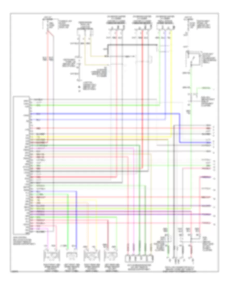
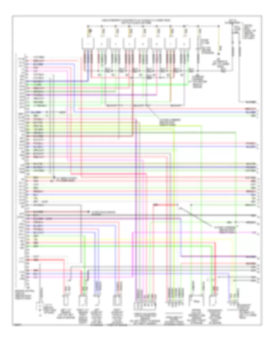
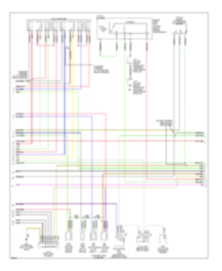
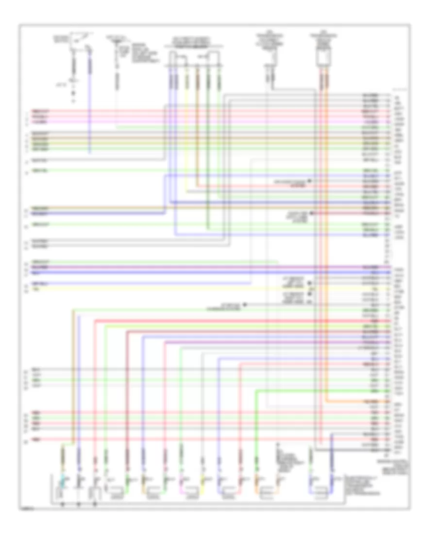
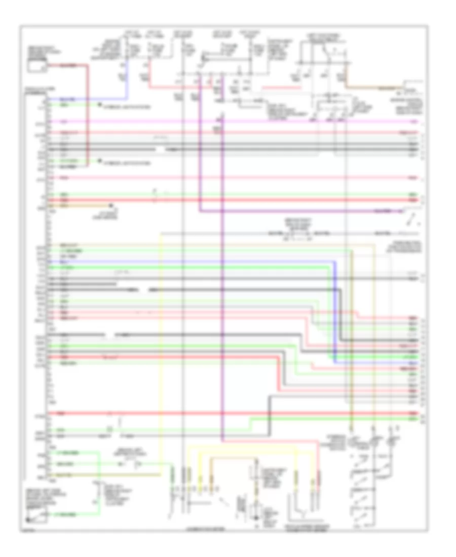
4.7L, Engine Performance Wiring Diagram (1 of 6) for Toyota Sequoia SR5 2006
List of elements for 4.7L, Engine Performance Wiring Diagram (1 of 6) for Toyota Sequoia SR5 2006:
- (4wd)
- (above respective spark plug, on each cylinder head) ignition coils & igniters
- (at rear of right cylinder head)
- (behind right end of dash)
- (in dash harness behind right side of dash)
- 4wd
- Acis
- Aip
- Aiv1
- Aiv2
- Camshaft position sensor (on front of left cylinder head)
- Crankshaft position sensor (on lower front of engine)
- E01
- E02
- E2 (in engine harness, at top center rear of engine)
- E2g
- Engine control module (behind right side of dash)
- Engine coolant temperature sensor (on right front of engine)
- Fpr
- G2+
- G2-
- Geo1
- Hot in on or start
- Ht1b
- I4 (in dash harness behind right side of dash)
- Igf1
- Igf2
- Ign 2 fuse 20a
- Igt1
- Igt2
- Igt3
- Igt4
- Igt5
- Igt6
- Igt7
- Igt8
- Inj 1
- Inj 2
- Inj 3
- Inj 4
- Inj 5
- Inj 6
- Inj 7
- Inj 8
- Instru- ment panel j/b (behind left end of dash)
- J/c 18
- Left camshaft timing oil control valve (top left of engine)
- Left vvt sensor (on top left side of engine)
- Mass airflow meter (on right front of engine compt)
- Nca
- Nca nca
- Ne+
- Ne-
- Noise filter (on top center of engine)
- Oc1+
- Oc1-
- Oc2+
- Oc2-
- Ox1b
- Pnk
- Prg
- Red
- Right camshaft timing oil control valve (on right front of engine)
- Right vvt sensor (right side of engine compt)
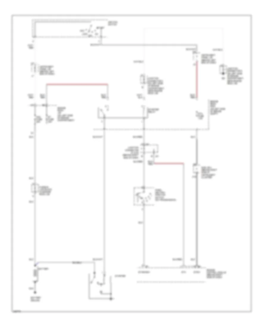
- Sta
- Starting/charging system
- Stsw
- Tha
- Throttle control motor & position sensor (on left front of engine, on throttle body)
- Thw
- Vta1
- Vta2
- Vv1+
- Vv1-
- Vv2+
- Vv2-
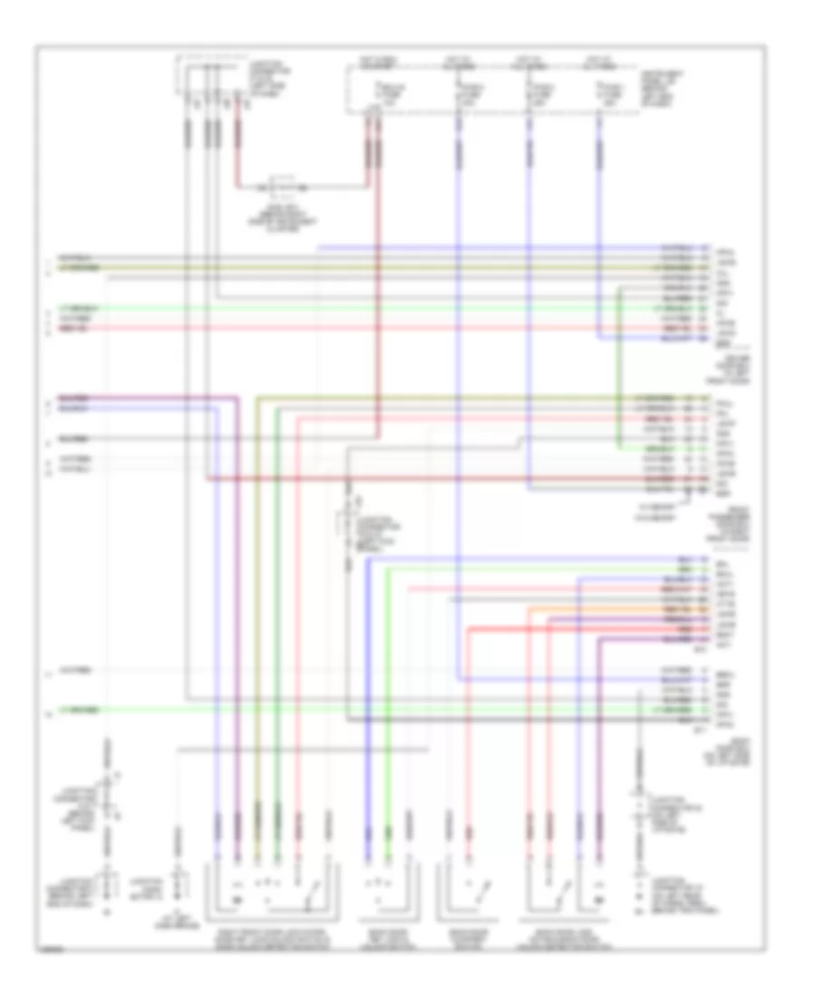
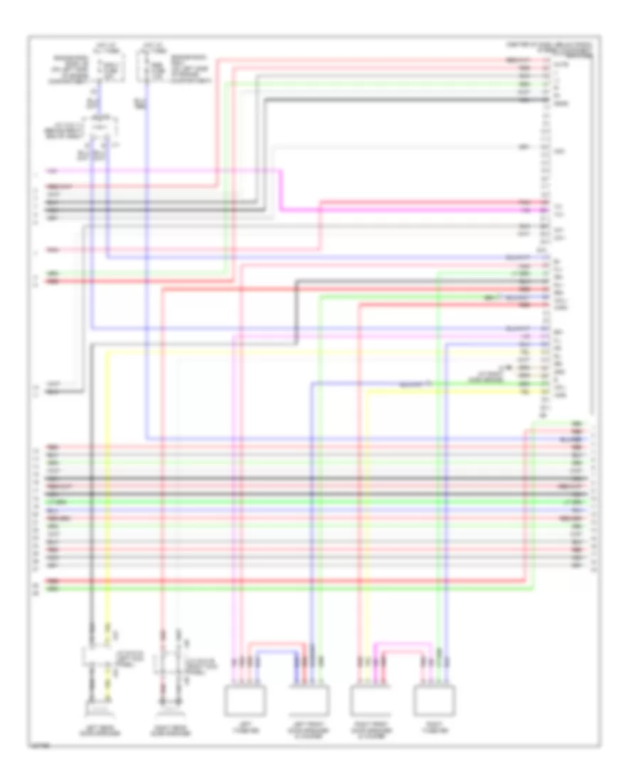
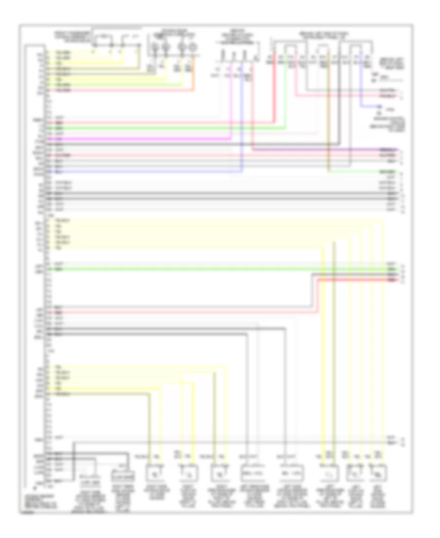
4.7L, Engine Performance Wiring Diagram (2 of 6) for Toyota Sequoia SR5 2006
List of elements for 4.7L, Engine Performance Wiring Diagram (2 of 6) for Toyota Sequoia SR5 2006:
- (in dash harness, behind right side of dash)
- (in engine harness, at top center rear of engine)
- (top of engine) air pressure sensor
- (top right side of engine)
- 4wd control ecu (4wd) (behind right center of dash)
- A/f fuse 20a
- A/f relay
- Add actuator (on rear of engine)
- Aip
- C/c
- Ec (at rear of left cylinder head)
- Engine room r/b 2 (on left side of engine compartment)
- F23 add
- Fuel injectors
- Hot at all times
- J/c 2 (on left side of engine com- partment near engine room j/b)
- J/c 42 (right side of dash)
- J/c 5 (on left side of engine com- partment near engine room j/b)
- J/c 51 & 52 (behind right end of dash)
- J51
- J52
- Nca
- Nca e
- Red
- Vsv (acis) (top left of engine)
- Vsv (air switching valve bank 1)
- Vsv (air switching valve bank 2)
- Vsv (evap) (top left side of engine)
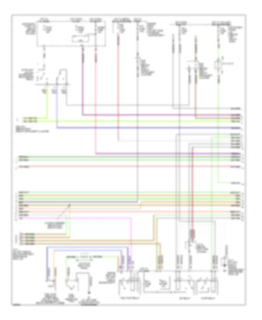
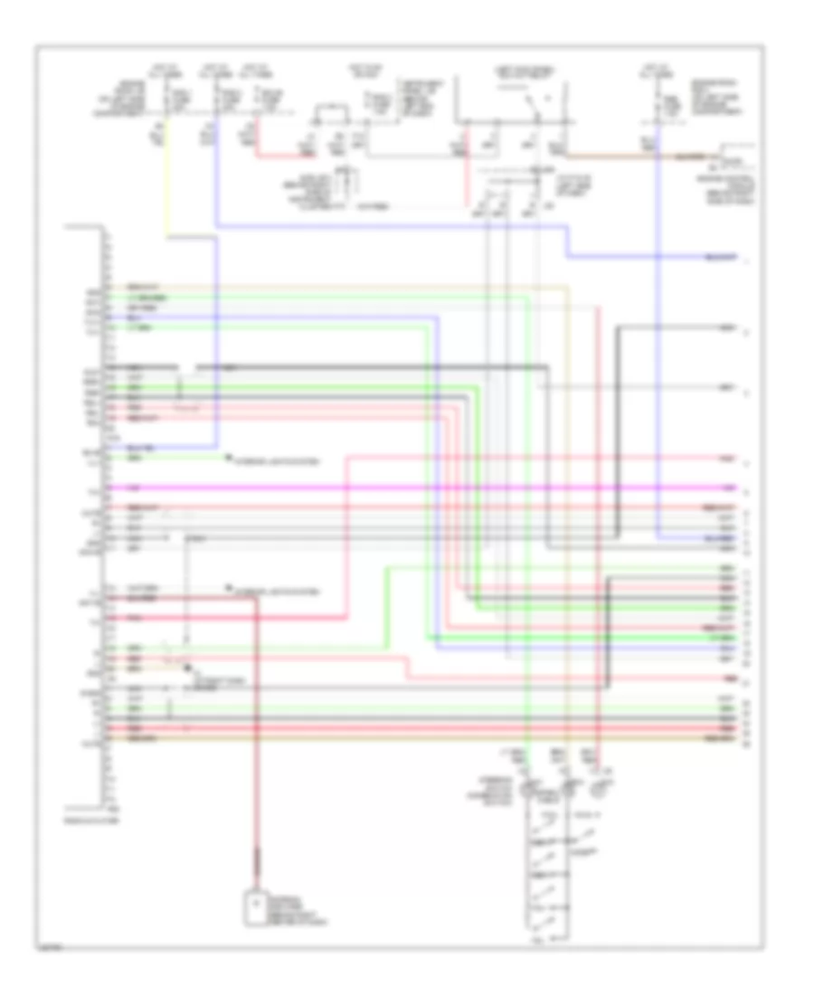
4.7L, Engine Performance Wiring Diagram (3 of 6) for Toyota Sequoia SR5 2006
List of elements for 4.7L, Engine Performance Wiring Diagram (3 of 6) for Toyota Sequoia SR5 2006:
- (in dash harness, behind right side of dash)
- A19
- Bi (at left side of room partition crossmember)
- C/opn relay
- Def i/up fuse 7.5a
- E17
- E18
- Efi 1 fuse 20a
- Efi 2 fuse 10a
- Efi relay
- Engine room j/b (on left side of engine compt)
- Engine room r/b 2 (on left side of engine compartment)
- Fuel pump (inside fuel tank)
- Fuel pump relay
- Fuel pump resistor (on left rear of engine compt, below master cylinder)
- Gauge fuse 15a
- H11
- Hot at all times
- Hot in run or acc
- Hot in run or start
- Hot in start
- Hot w/ defog relay energized
- Hot w/ taillight relay energized
- Ign 1 fuse 10a
- Instrument panel j/b (behind left end of dash)
- Ipo
- J/c 16 (behind right end of dash)
- J/c 2 (on left side of eng compartment, near engine room j/b)
- J/c 44 & 45 (right kick panel)
- J/c 5 (on left side of engine compartment near engine room j/b)
- J14
- J15 j/c 14 & 15
- J44
- J45
- Rad 2 fuse 7.5a
- Sta fuse 7.5a
- Stop fuse 15a
- Stoplight switch (on bracket, above brake pedal)
- Sub j/b 4 (behind right side of instrument cluster)
- Tail fuse 15a
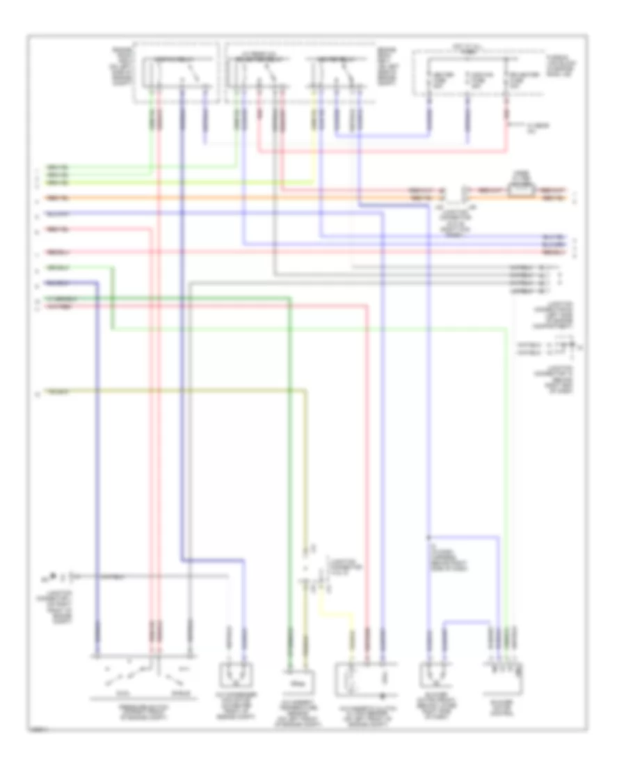
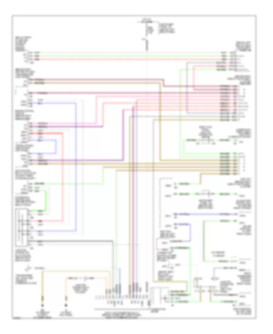
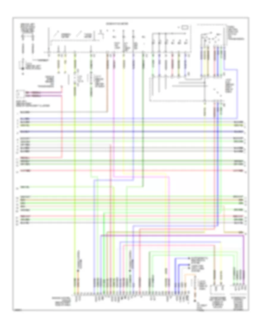
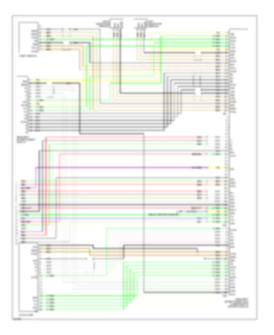
4.7L, Engine Performance Wiring Diagram (4 of 6) for Toyota Sequoia SR5 2006
List of elements for 4.7L, Engine Performance Wiring Diagram (4 of 6) for Toyota Sequoia SR5 2006:
- (4wd)
- (behind left end of dash) instrument panel j/b
- 2lo
- A/t oil temp ind
- A15
- Ac1
- Act
- Canh
- Canl
- Ccs
- Combination meter
- Computer data lines system
- Efii
- Efio
- Els1
- Els2
- Engine control module (behind right side of dash)
- Eom
- F/ps
- Ig (at right kick panel)
- Imi
- Imo
- Integration control & panel (behind center of dash)
- J/c & 15
- J/c 17 (behind left center of dash)
- J/c 43 (right side of dash)
- J/c 51 & 52 (behind right end of dash)
- J/c 8 (behind left end of dash)
- J14
- J15
- J51
- J52
- Llp
- Lms
- Malf ind lamp
- O/d off ind
- Odlp
- Oilw
- Park/ neutral position switch (on transmission)
- Spd
- Speedo- meter
- Sub j/b 3 (behind right side of instrument cluster)
- System cruise control
- Tach
- Tacho- meter
- Thwo
- Transponder key computer (inside of steering column)
- Vehicle speed sensor (on transmission)
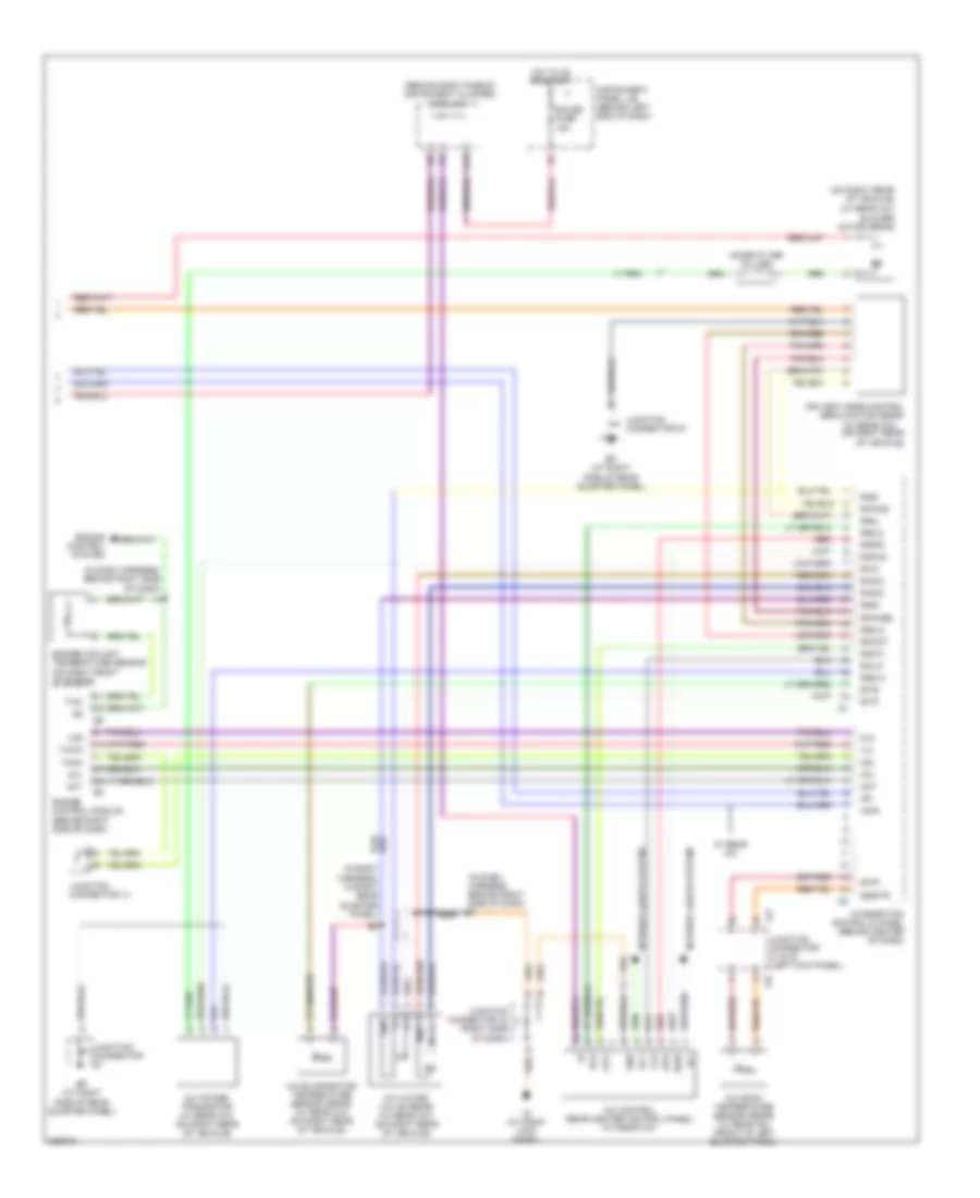
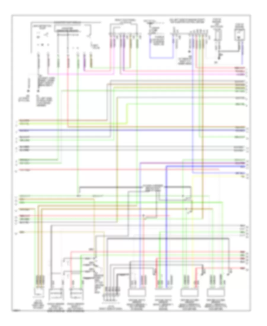
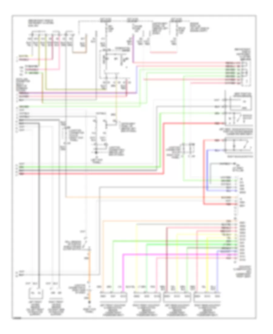
4.7L, Engine Performance Wiring Diagram (5 of 6) for Toyota Sequoia SR5 2006
List of elements for 4.7L, Engine Performance Wiring Diagram (5 of 6) for Toyota Sequoia SR5 2006:
- (in dash harness, behind right side of dash)
- (on left side of engine compt) air injector control driver
- (right kick panel) j/c 48 & 49
- (top of engine) air pump
- (top of engine) air switching valve
- A/pump fuse 50a
- A40
- A41
- Air fuel ratio sensor (bank 1 sensor 1) (top of engine)
- Air fuel ratio sensor (bank 2 sensor 1) (on top rear of engine)
- B3 (in body harn -ness, under left side of rear seat)
- Batt
- Bi (at left side of room part- ition cross- member)
- Bk (at right "b" pillar)
- Canister pressure sensor
- Canister pump module
- E1 (engine harn- ess, at top center rear of eng)
- Eb (at rear of right cyl- inder head)
- Fusible link block (in engine room j/b)
- Heated oxygen sensor (bank 1 sensor 2) (rear of catalytic converter)
- Heated oxygen sensor (bank 2 sensor 2) (rear of catalytic converter)
- Hot at all times
- J/c 16 (behind right end of dash)
- J/c 42 (right side of dash)
- J48
- J49
- Knock sensor (bank 1) (on top right side of engine)
- Knock sensor (bank 2) (on top left side of engine)
- Leak detection pump
- Nca
- Red
- Sip
- Siv
- Vent valve
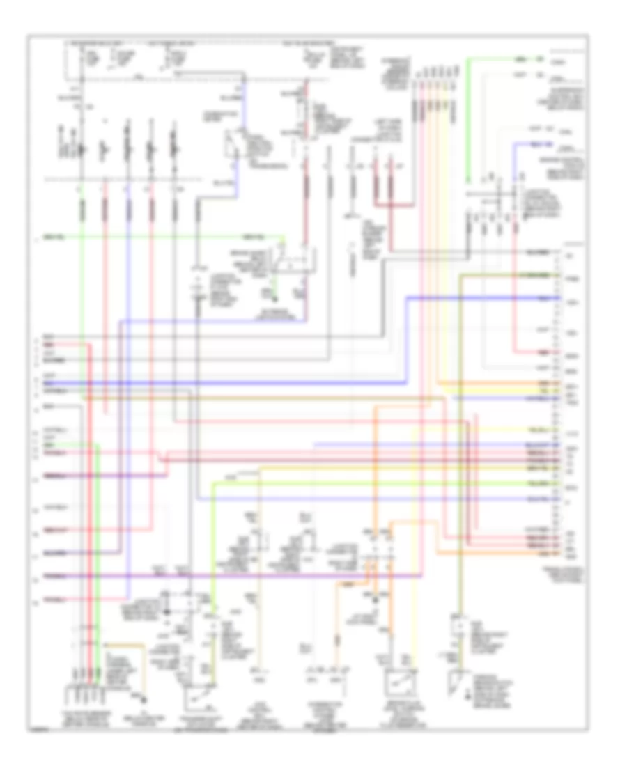
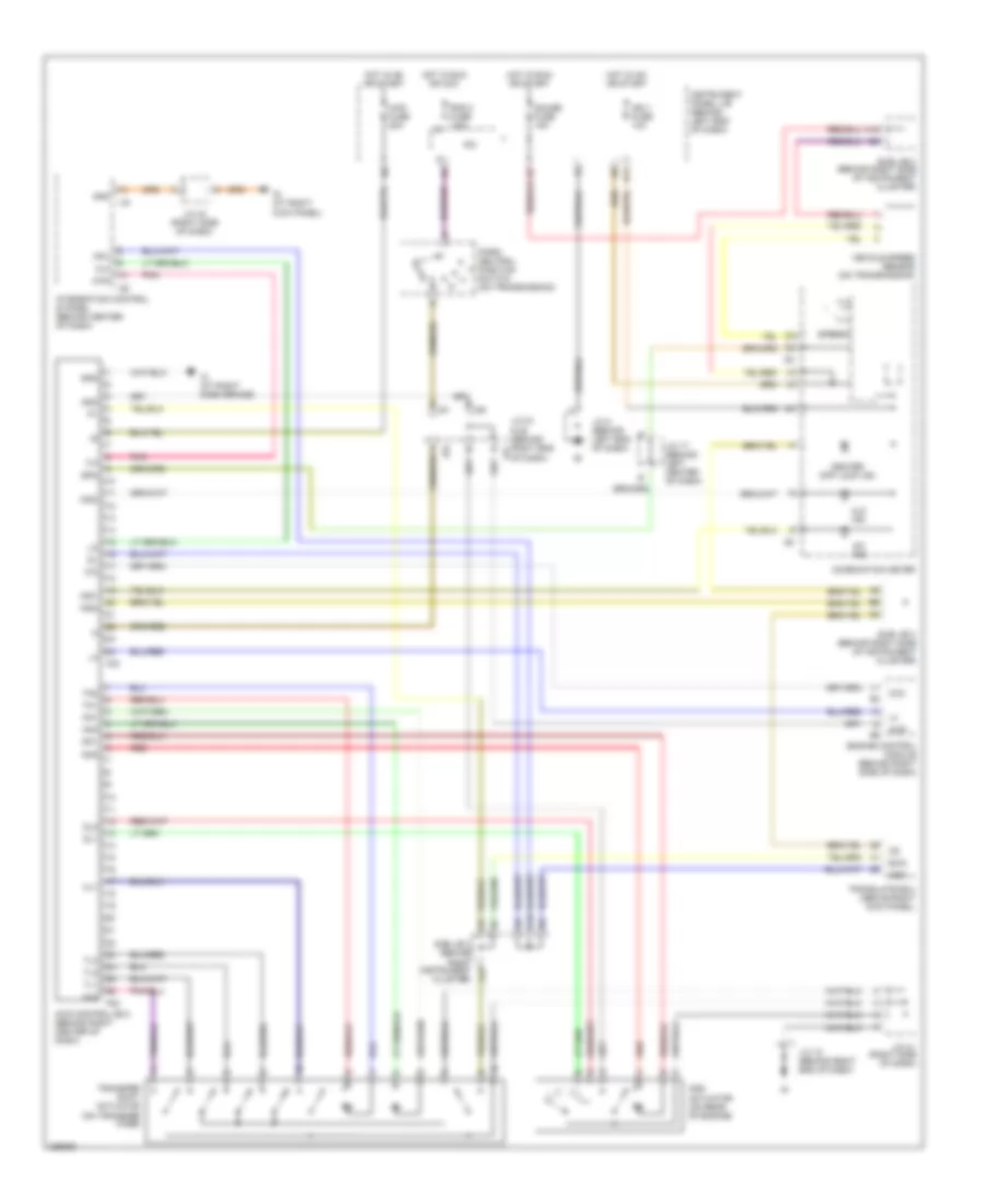
4.7L, Engine Performance Wiring Diagram (6 of 6) for Toyota Sequoia SR5 2006
List of elements for 4.7L, Engine Performance Wiring Diagram (6 of 6) for Toyota Sequoia SR5 2006:
- (at rear of left cyl- inder head)
- (at rear of right cyl- inder head)
- (on throttle body) accelerator pedal position sensor
- (on transmission) o/d direct clutch speed sensor
- (on transmission) vehicle speed sensor
- +b2
- +bm
- A1a+
- A1a-
- A2a+
- A2a-
- Accr
- Aidi
- Air conditioning system
- Airp
- Airv
- Batt
- Ccc
- Computer data lines system
- E03
- Ekn2
- Eknk
- Electronically controlled transmission solenoid (on transmission)
- Els
- Engine control module (behind right side of dash)
- Engine room j/b (on left side of engine compartment)
- Eo4
- Eo5
- Epa
- Epa2
- Etcs fuse 10a
- Ha1a
- Ha2a
- Hot at all times
- Ht2b
- Igsw
- J/c 12
- Knk1
- Knk2
- Me01
- Mpmp
- Mrel
- Nt+
- Nt-
- O/d main switch
- Ot+
- Ot-
- Ot2+
- Ot2-
- Ox2b
- Ppmp
- Red
- Sl1+
- Sl1-
- Sl2+
- Sl2-
- Slt+
- Slt-
- Slu+
- Slu-
- Sp2+
- Sp2-
- St1-
- Star
- Starting/ charging system
- Stp
- Tho1
- Tho2
- Vcp2
- Vcpa
- Vpa
- Vpa2
- Vpmp
EXTERIOR LIGHTS
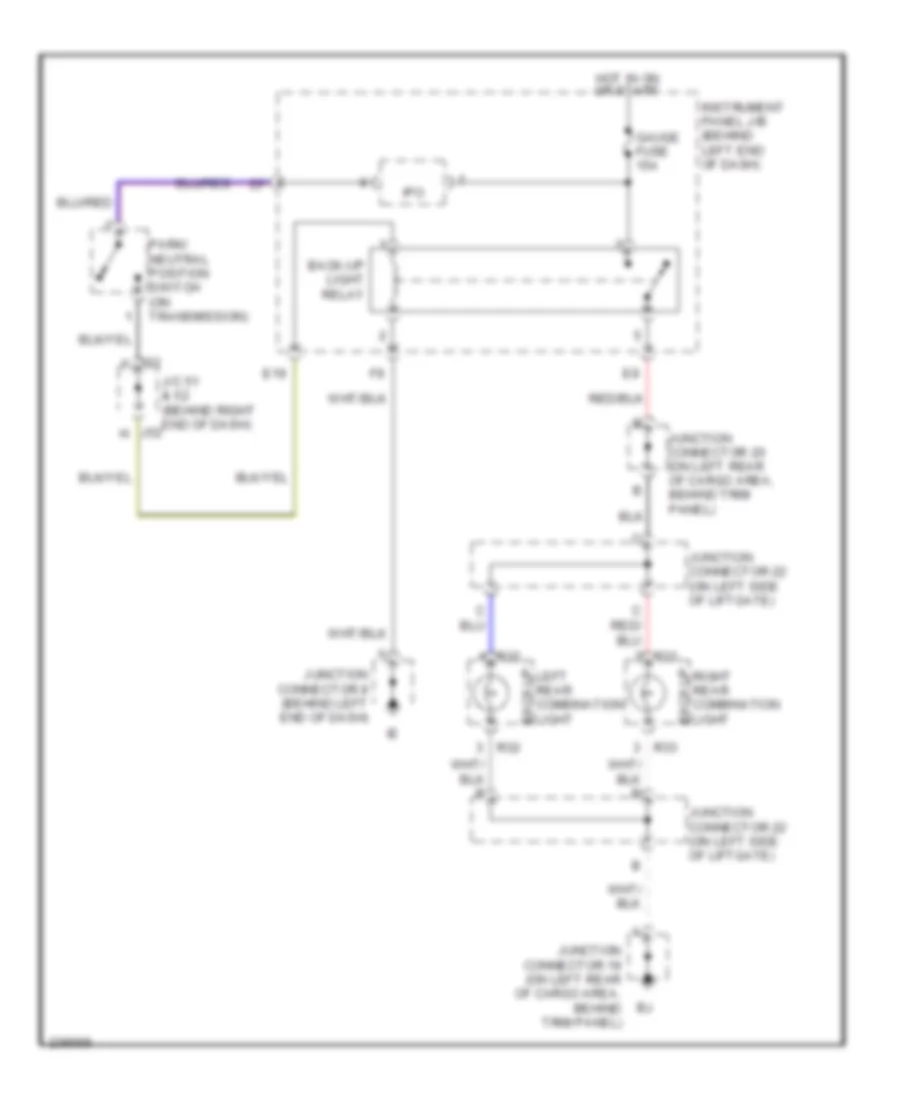
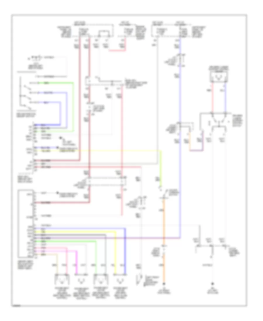
Back-up Lamps Wiring Diagram for Toyota Sequoia SR5 2006
List of elements for Back-up Lamps Wiring Diagram for Toyota Sequoia SR5 2006:
- Back-up
- Back-up light relay
- E19
- Gauge fuse 15a
- Hot in on or start
- Instrument panel j/b (behind left end of dash)
- Ipo
- J/c 51 & 52 (behind right end of dash)
- J51 f
- J52 h
- Junction connector 19 (on left rear of cargo area, behind trim panel)
- Junction connector 20 (on left rear of cargo area, behind trim panel)
- Junction connector 22 (on left side of liftgate)
- Junction connector 8 (behind left end of dash)
- Left rear combination light
- Park/ neutral position switch (on transmission)
- R32
- R33
- Right rear combination light
Exterior Lamps Wiring Diagram for Toyota Sequoia SR5 2006
List of elements for Exterior Lamps Wiring Diagram for Toyota Sequoia SR5 2006:
- (behind left end of dash) instrument panel j/b
- (behind left end of dash) junction connector 9
- (combi- nation switch) turn signal switch
- (near engine room j/b) junction connector 28
- (on left rear of cargo area, behind trim panel) j/c 20
- (on left side of engine compt, near engine room j/b) junction connector 3
- (on right front of engine compt) junction connector 1
- A j30
- Alt fuse 140a
- Body ecu (behind left end of dash)
- Brake inhibit relay (behind left center of dash)
- Bsw
- C j44
- Combination meter
- E j30
- E11
- E18
- Ecu- b fuse 7.5a
- Ecu-ig fuse 10a
- Ehw
- Engine room j/b (on left side of engine compt)
- Fusible link block (in engine room j/b)
- Gauge fuse 15a
- Gnd
- Hazard switch (integration control & panel)
- Head
- High mounted stop light
- Hot at all times
- Hot in on or start
- Instrument panel j/b (behind left end of dash)
- J/c 18 (behind right end of dash)
- J/c 29 & 30 (left kick panel)
- J/c 37 & 38 (left side of dash)
- J/c 50 (left side of engine comp)
- J/c 57 (right rear corner, below taillamp)
- J/c 8 (behind left end of dash)
- J10
- J11
- J14
- J15
- J29
- J33 j/c 33 & (left kick j34 panel)
- J37 a
- J38 a
- J45 j
- J46 b
- J47 f
- Junction connector 10 & 11 (behind right end j10 of dash)
- Junction connector 12 (center of dash, left of radio)
- Junction connector 14 & 15
- Junction connector 19 (on left rear of cargo area, behind trim panel)
- Junction connector 21 (on left rear of cargo area, behind trim panel)
- Junction connector 22 (on left side of liftgate)
- Junction connector 29 & 30 (left kick panel)
- Junction connector 3 (on left side of engine compt, near engine room j/b)
- Junction connector 44 & 45 (right kick panel)
- Junction connector 46 & 47 (right kick panel)
- Junction connector 5 (on left side of engine compt, near engine room j/b)
- Junction connector 8 (behind left end of dash)
- Junction connector 9 (behind left end of dash)
- L j29
- Left front park light 3
- Left front park/ turn light 1
- Left front park/ turn light 2
- Left rear combin- ation light
- Left turn indicator
- License plate light
- Light control switch (combination switch)
- Off
- Park
- R32
- R33
- Right front park light 3
- Right front park/ turn light
- Right front park/ turn light 1
- Right rear combin- ation light
- Right turn indicator
- Skid control ecu w/ actuator (on right rear of engine compt)
- Stop
- Stop fuse 15a
- Stop light switch (on bracket, above brake pedal)
- Sub j/b 3 (behind right side of instrument cluster)
- Sub j/b 4 (behind right side of instrument cluster)
- Tail
- Tail fuse 15a
- Tail ind (canada)
- Taillight relay
- Trly
- Turn
- Turn signal flasher relay (behind left end of dash, below instrument panel j/b)
- Turn- haz fuse 20a
- W/ rear spoiler
- W/o rear spoiler
Trailer Tow Wiring Diagram for Toyota Sequoia SR5 2006
List of elements for Trailer Tow Wiring Diagram for Toyota Sequoia SR5 2006:
- (trailer socket 7 pin type) back-up light relay
- (trailer socket 7 pin type) batt charge relay
- 4 pin type
- 7 pin type
- A j11
- A15
- B/up
- Back-up lamps circuit
- Batt
- Batt charge fuse 30a
- Body ecu (behind left end of dash)
- Brake inhibit relay (behind left center of dash)
- Brk
- Bsw
- E18
- E19
- Ecu-ig fuse 10a
- Engine room j/b (on left side of engine compt)
- Engine room r/b 3 (on left side of engine compt)
- Gauge fuse 15a
- Gnd
- Hot at all times
- Hot in on or start
- Ig (at right kick panel)
- Instrument panel j/b (behind left end of dash)
- Ipo
- J/c 10 & 11 (behind right end of dash)
- J/c 19 (on left rear of cargo area, behind trim panel)
- J/c 20 (on left rear of cargo area, behind trim panel)
- J/c 28 (near engine room j/b)
- J/c 29 & 30 (left kick panel)
- J/c 33 & 34 (left kick panel)
- J/c 37 & 38 (left side of dash) j38
- J/c 43 (right side of dash)
- J/c 9 (behind left end of dash)
- J29
- J30 e
- J33
- J37
- Junction connector
- K12
- Ltin
- Ltot
- Red
- Rtin
- Rtot
- Skid control ecu w/actuator (on right rear of engine compartment)
- Stin
- Stop
- Stop fuse 15a
- Stop light switch (on bracket above brake pedal)
- Sttl
- Sttr
- Sub j/b 3 (behind right side of instrument cluster)
- Sub j/b 4 (behind right side of instrument cluster)
- Tail
- Tail fuse 15a
- Towing brake controller (trailer socket 7 pin type) (at left kick panel)
- Towing brk fuse 30a
- Towing converter relay (on left side of cargo area, behind trim panel)
- Towing fuse 30a
- Towing tail fuse 30a
- Towing tail relay
- Trailer socket
- Trly
- Turn signal flasher relay (behind left end of dash, below instrument panel j/b)
- Turn- haz fuse 20a
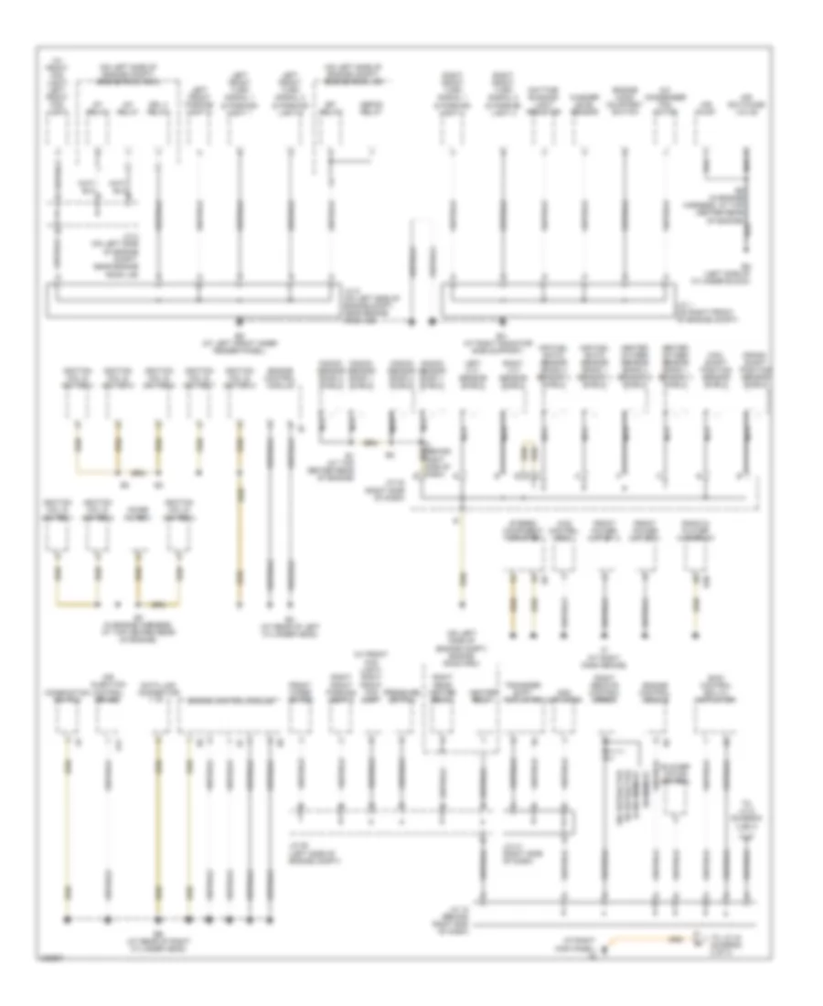
GROUND DISTRIBUTION
Ground Distribution Wiring Diagram (1 of 3) for Toyota Sequoia SR5 2006
List of elements for Ground Distribution Wiring Diagram (1 of 3) for Toyota Sequoia SR5 2006:
- (at right kick panel) ig
- (at right radiator side support)
- (on left side of engine compt) engine room j/b
- (on left side of engine compt) engine room r/b 2
- (on left side of engine compt) engine room r/b 4
- (w/ front fog light) left front fog light
- (w/ front fog light) right front fog light
- 4wd control ecu
- A/c condenser fan motor
- A/f relay
- A41
- Add actuator
- Air fuel ratio sensor (bank 1 sensor 1) shield
- Air fuel ratio sensor (bank 2 sensor 1) shield
- Air injection control driver
- Air pump
- Air switching valve
- Blower motor control
- Cam- shaft position sensor shield
- Combination switch
- Crank- shaft position sensor shield
- Data link connector
- Daytime running light resistor
- Defog relay
- Drl 4 relay
- E1 (at top center rear of engine)
- E2 (in engine harness, at top center rear of engine)
- Eb (at rear of right cylinder head)
- Ec (at rear of left cylinder head)
- Ed (at left front inner fender panel)
- Efi relay
- En (left side of cylinder block)
- Engine control module
- Engine hood courtesy switch
- Front power outlet 1
- Front power outlet 2
- Front wiper motor
- Heated oxygen sensor (bank 1 sensor 1) shield
- Heated oxygen sensor (bank 2 sensor 2) shield
- Heater relay
- I4 (behind right side of dash) e
- Ignition coil & igniter 1
- Ignition coil & igniter 2
- Ignition coil & igniter 3
- Ignition coil & igniter 4
- Ignition coil & igniter 5
- Ignition coil & igniter 6
- Ignition coil & igniter 7
- Ignition coil & igniter 8
- Io (at right dash brace)
- J/c 1 (on right front of engine compt)
- J/c 18 (behind right end of dash)
- J/c 2 (on left side of engine compt, near engine room j/b)
- J/c 41 (right side of dash)
- J/c 42 (right side of dash)
- J/c 5 (on left side of engine compt, near engine room j/b)
- J/c 50 (left side of engine compt)
- Knock sensor bank 1 shield
- Knock sensor bank 2 shield
- Left front parking light 3
- Left front turn signal 1 & parking light 1
- Left front turn signal 2 & parking light 2
- Left vvt sensor shield
- Nca
- Noise filter 1
- Pressure switch
- R30
- Radio & player w/ display
- Right front parking light 3
- Right front turn signal 1 & parking light 1
- Right front turn signal 2 & parking light 2
- Right rear heater relay
- Right remote control mirror
- Right vvt sensor shield
- Skid control ecu w/ actuator
- St relay
- Stereo component amplifier
- To j/c 43 (diagram 2 of 3)
- To j/c 8 (diagram 2 of 3)
- Transfer shift actuator
- W/ memory
- W/ retractor & w/o memory
- W/o retractor
- Washer level sensor
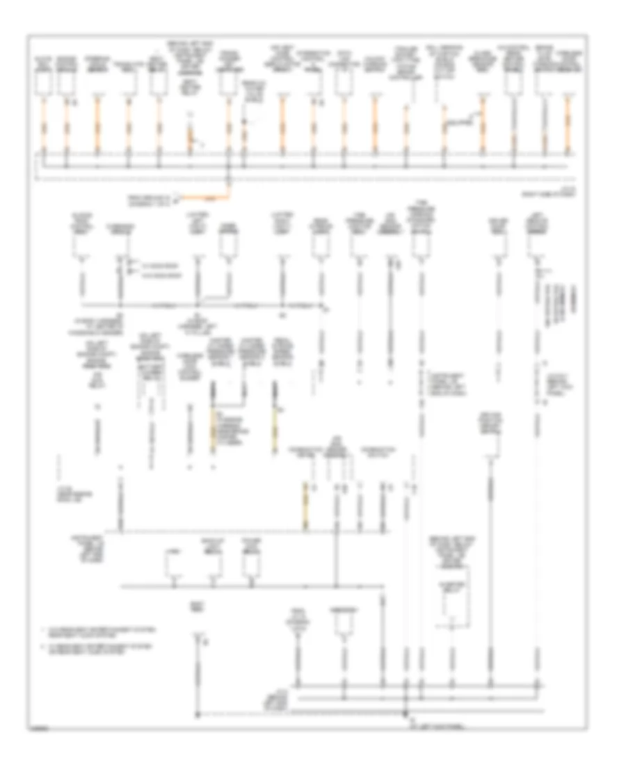
Ground Distribution Wiring Diagram (2 of 3) for Toyota Sequoia SR5 2006
List of elements for Ground Distribution Wiring Diagram (2 of 3) for Toyota Sequoia SR5 2006:
- (behind left end of dash, below instrument panel j/b) driver side r/b
- (behind left end of dash, below instrument panel j/b) driver side r/b
- (limited) left vanity light
- (limited) right vanity light
- (on left side of engine compt) engine room r/b 2
- (on left side of engine compt) engine room r/b 3
- (trailer socket 7-pin type) towing brake controller
- A/c control (rear heater control panel)
- A20
- Air bag sensor assembly
- Air sus relay
- Air vent mode control servo motor (front)
- B1 (in body harness, left "a" pillar)
- B2 (in body harness, at center of windshield header)
- Back-up light relay
- Battery charge relay
- Body ecu
- Brake fluid level warning switch
- C10
- Combination meter
- Combination switch
- Data link connector
- Driver door ecu
- Driving position memory switch
- E3 (in engine harness, near brake master cylinder)
- Engine control module
- F10
- From ground ig b (diagram 1 of 3)
- From j/c 18 (diagram 1 of 3)
- Glass breakage sensor ecu
- Glove box light
- I19
- Ie (at left kick panel)
- If equipped
- Inner mirror
- Instrument panel j/b (behind left end of dash)
- Integration control & panel
- Inverter relay
- Ipo
- J/c 28 (near engine room j/b)
- J/c 43 (right side of dash)
- J/c 6 & 7 (behind left kick panel)
- J/c 8 (behind left end of dash)
- K12
- Left remote control mirror
- Master cylinder pressure sensor 1 shield
- Master cylinder pressure sensor 2 shield
- Nca
- Overhead module
- Pedal stroke speed sensor shield
- Power main relay
- Rear a/c water valve shield
- Rear interior light
- Rheostat
- Roll sensing of curtain shield air bag cut off switch
- Seat heater relay
- Sliding roof control ecu
- Steering angle sensor
- Tire pressure monitor ecu
- Tire pressure warning standard- ization switch
- Trans- ponder key computer
- Translate ecu
- Unlock warning switch
- W/ memory
- W/ moon roof
- W/ rear seat entertainment system or rear seat audio system
- W/ retractor & w/o memory
- W/o moon roof
- W/o rear seat entertainment system, rear seat audio system
- W/o retractor
- Wireless door control receiver
- Wireless door lock control buzzer
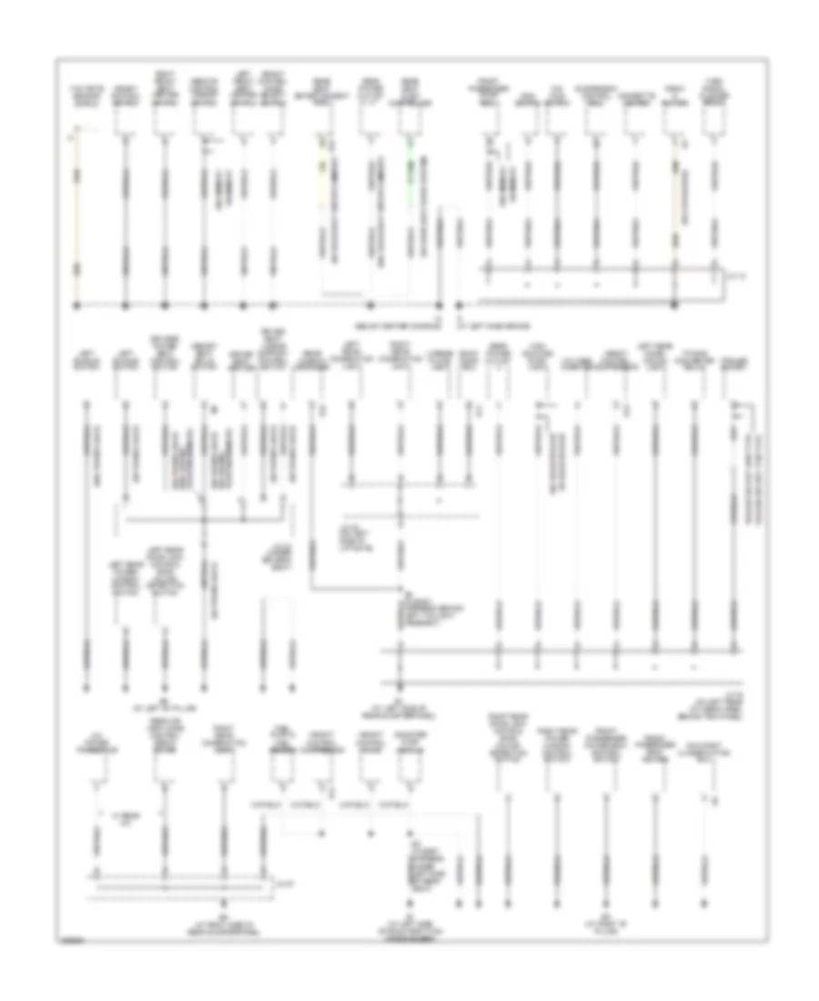
Ground Distribution Wiring Diagram (3 of 3) for Toyota Sequoia SR5 2006
List of elements for Ground Distribution Wiring Diagram (3 of 3) for Toyota Sequoia SR5 2006:
- (w/ 6 speakers)
- (w/ power seat)
- (w/ power seat) (w/o driving position memory)
- (w/ rear seat audio system)
- (w/ rear seat entertainment)
- (w/o power seat)
- (w/o rear seat entertainment)
- A/c power transistor
- B11
- B3 (in body harness, under left side of rear seat)
- B4 (in body harness, behind left taillight assembly)
- Back door ecu
- Bh (at left "b" pillar)
- Bi (at left side of room partition crossmember)
- Bj (at left side of rear quarterpanel)
- Bk (at right "b" pillar)
- Bp (at right side of rear quarterpanel)
- Canister pump module
- Cigarette lighter
- Driver seat heater
- Driver seat lumbar support control switch
- Driver's power seat control switch
- Front passenger door ecu
- Front passenger power seat control switch
- Front passenger seat heater
- Fuel pump & fuel sender
- H13
- H14
- Height control compressor
- Height control mode select switch
- Height control switch
- Height control valve
- High mounted stop- light
- If (at left dash brace)
- Im (below center console)
- J/c 12
- J/c 19 (on left rear of cargo area, behind trim panel)
- J/c 22 (on left side of liftgate)
- J/c 24 (under driver's seat)
- J/c 57
- Left buckle switch
- Left front seat heater switch
- Left rear combi- nation light
- Left rear combination light
- Left rear door lock motor & door unlock detection switch
- Left rear power window control switch
- License plate light
- Main switch
- Memory seat ecu & switch
- O/d main switch
- Occupant classification ecu
- Position memory) (w/ driving
- R15
- R23
- Radio & player
- Rear air vent mode control servo motor
- Rear power outlet
- Rear seat audio controller
- Rear seat entertainment ecu
- Rear window defogger
- Remote control mirror switch
- Right front seat heater switch
- Right rear combination light
- Right rear door lock motor & door unlock detection switch
- Right rear power window control switch
- Suspension control ecu
- Towing converter relay
- Trailer socket
- Trailer socket 4pin type
- Trailer socket 7pin type
- Turn signal flasher relay
- Voltage inverter
- W/ memory
- W/ rear a/c
- W/ rear spoiler
- W/o memory
- W/o rear spoiler
- Yaw rate sensor shield
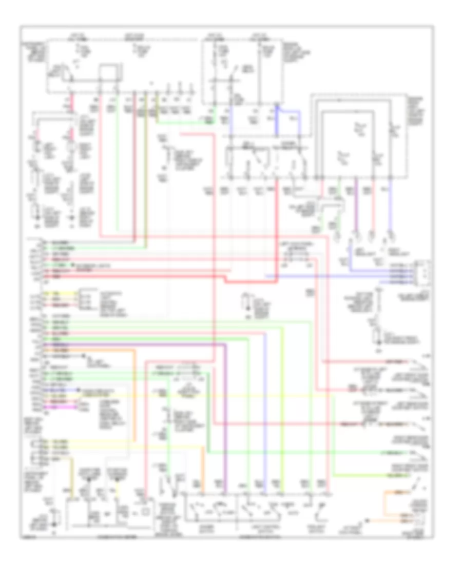
HEADLIGHTS
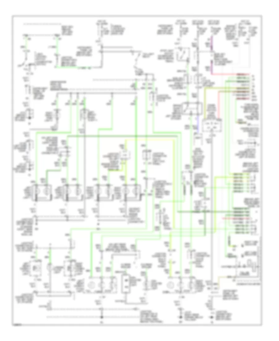
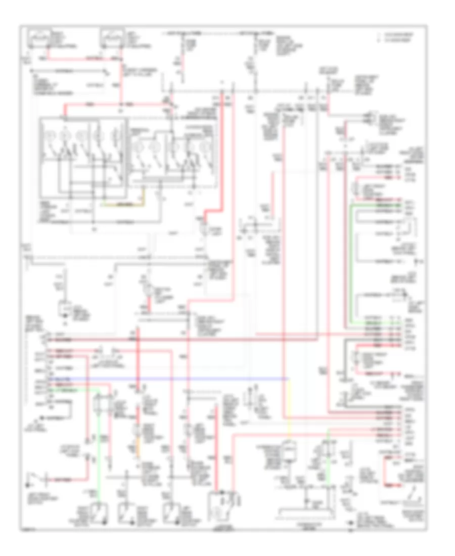
Headlights Wiring Diagram, with DRL for Toyota Sequoia SR5 2006
List of elements for Headlights Wiring Diagram, with DRL for Toyota Sequoia SR5 2006:
- (at base of left "b" pillar) (interior light 2) diode
- (at base of right "b" pillar) (interior light 1) diode
- (left kick panel) j/c 29 & 30
- (usa)
- Auto
- Automatic light control sensor (on top left side of dash)
- Becu
- Body ecu (behind left end of dash)
- Cltb
- Clte
- Clts
- Combination meter
- Combination switch
- Computer data lines system
- Daytime running light resistor (behind left headlight)
- Dcty
- Dim
- Dimmer relay
- Dimmer switch
- Drl 4 relay
- Drl fuse 15a
- Ecu-b fuse 7.5a
- Ecu-ig fuse 10a
- Engine room j/b (on left side of engine compt)
- Engine room r/b 2 (on left side of engine compt)
- Exterior lights system
- Ffog
- Flash
- Fog fuse 15a
- Fog light relay
- Foglight switch
- G11
- Gnd1
- H-lp lh 10a
- H-lp ll 10a
- H-lp rh 10a
- H-lp rl 10a
- H-on
- Head
- Head ind
- Head relay
- High
- High beam ind
- Hind
- Hot at all times
- Hot in on or start
- Hrly
- Ie (at left kick panel)
- Ig (at right kick panel)
- Instrument panel j/b (behind left end of dash)
- J/c 1 (on right front of engine compt)
- J/c 18 (behind right end of dash)
- J/c 2 (on left side of engine compt)
- J/c 3 (on left side of engine compt)
- J/c 4 (on left side of engine compt)
- J/c 43 (right side of dash)
- J/c 44 & 45 (right kick panel)
- J/c 5 (on left side of engine compt)
- J/c 50 (left side of engine compt)
- J/c 8 (behind left end of dash)
- J10
- J29
- J30
- J44
- J45
- Ksw
- Left front door courtesy switch
- Left front fog light
- Left headlight
- Left rear door courtesy switch
- Light control switch
- Low
- Main fuse 40a
- Mpx2
- Off
- Parking brake switch (behind left side of dash, on parking brake lever)
- Pcty
- Pkb
- Pnk
- Prg
- Rda
- Red
- Right front door courtesy switch
- Right front fog light
- Right headlight
- Right rear door courtesy switch
- Rlcy
- Rrcy
- Starting/ charging system
- Sub j/b 3 (behind right side of instrument cluster)
- Sub j/b 4 (behind right side of instrument cluster)
- Tail
- Trly
- Unlock warning switch
- Wireless door control receiver (center of dash, below radio)
Headlights Wiring Diagram, without DRL for Toyota Sequoia SR5 2006
List of elements for Headlights Wiring Diagram, without DRL for Toyota Sequoia SR5 2006:
- (left kick panel)
- (right kick panel)
- (usa)
- Auto
- Automatic light control sensor (if equipped) (on top left side of dash)
- Becu
- Body ecu (behind left end of dash)
- Cltb
- Clte
- Clts
- Combination meter
- Combination switch
- Computer data lines system
- Dcty
- Dimmer switch
- Diode (interior light 1) (at base of right "b" pillar)
- Diode (interior light 2) (at base of left "b" pillar)
- Ecu-b fuse 7.5a
- Ecu-ig fuse 10a
- Engine room j/b (on left side of engine compt)
- Exterior lights system
- Ffog
- Flash
- Fog fuse 15a
- Fog light relay
- Foglight switch
- G11
- H-lp (left) fuse 15a
- H-lp h-lp (right) fuse fuse 15a 15a
- Head
- Head ind
- Head relay
- High
- High beam ind
- Hot at all times
- Hot in on or start
- Hrly
- Ig (at right kick panel)
- Instrument panel j/b (behind left end of dash)
- J/c 18 (behind right end of dash)
- J/c 2 (on left side of engine compt)
- J/c 29 & 30
- J/c 29 & 30 (left kick panel)
- J/c 3 (on left side of engine compt)
- J/c 4 (on left side of engine compt, near engine room j/b)
- J/c 43 (right side of dash)
- J/c 44 & 45
- J/c 5 (on left side of engine compt)
- J/c 50 (left side of engine compt)
- J/c 8 (behind left end of dash)
- J10
- J29
- J30
- J44
- J45
- Ksw
- Left front door courtesy switch
- Left front fog light
- Left headlight
- Left rear door courtesy switch
- Light control
- Light control switch
- Low
- Main fuse 40a
- Mpx2
- Off
- Parking brake switch (behind left side of dash, on parking brake lever)
- Pcty
- Pkb
- Pnk
- Prg
- Rda
- Right front door courtesy switch
- Right front fog light
- Right headlight
- Right rear door courtesy switch
- Rlcy
- Rrcy
- Sub j/b 3 (behind right side of instrument cluster)
- Sub j/b 4 (behind right side of instrument cluster)
- Tail
- Trly
- Unlock warning switch
- W/ automatic
- Wireless door control receiver (if equipped) (center of dash, below radio)
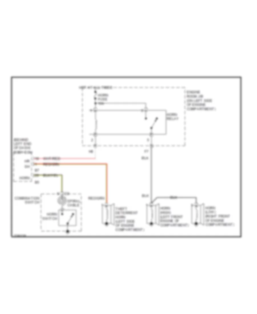
HORN
Horn Wiring Diagram for Toyota Sequoia SR5 2006
List of elements for Horn Wiring Diagram for Toyota Sequoia SR5 2006:
- (behind left end of dash)
- Body ecu
- Combination switch
- Engine room j/b (on left side of engine compartment)
- Horn
- Horn (high) (left front engine of compartment)
- Horn (low) (right front of engine compartment)
- Horn fuse 10a
- Horn relay
- Horn switch
- Hot at all times
- Spiral cable
- Theft deterrent horn (left side of engine compartment)
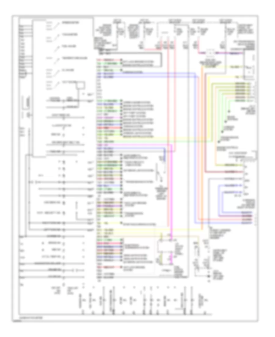
INSTRUMENT CLUSTER
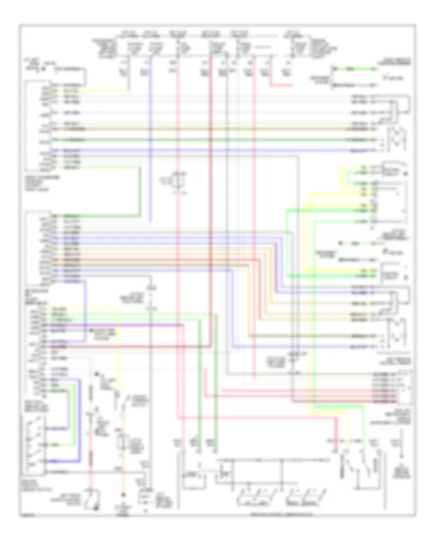
Instrument Cluster Wiring Diagram (1 of 2) for Toyota Sequoia SR5 2006
List of elements for Instrument Cluster Wiring Diagram (1 of 2) for Toyota Sequoia SR5 2006:
- (behind right side of instrument cluster) sub j/b 4
- (canada) tail ind
- (on transmission) vehicle speed sensor (combination meter)
- (usa) head ind
- 4hi ind
- 4lo ind
- A/t oil temp ind
- A10
- A11
- A12
- A13
- A14
- A15
- A16
- A17
- A18
- A19
- A20
- A21
- A22
- A23
- A24
- A25
- A26
- A27
- A28
- A29
- A30
- A31
- A32
- A33
- A34
- A35
- A36
- A37
- A38
- A39
- A40
- Abs ind
- Anti-lock brakes system
- Anti-theft system
- B10
- B11
- B12
- B13
- B14
- B15
- B16
- B17
- B18
- B19
- B2 (in body harness, at center of windshield header)
- B20
- B21
- B22
- B23
- B24
- Brake ind
- Buzzer
- Charge ind
- Combination meter
- Computer data lines system
- Cruise ind
- Door ind
- Driver's seat belt ind
- E/m
- Ecu-b fuse 7.5a
- Ecu-ig fuse 10a
- Electronic suspension system
- Engine controls system
- Engine room j/b (on left side of engine compt)
- Engine room r/b 2 (on left side of engine compt)
- Exterior lights system
- F10
- Fuel gauge
- Fuel ind
- Fuel pump & sender (inside fuel tank)
- Gauge fuse 15a
- Gnd
- H11
- Headlights system
- High beam ind
- Hot at all times
- Hot in run or start
- Hot in start
- Ig+
- Ign1 fuse 10a
- Ign2 fuse 20a
- Illumination ind
- Instrument panel j/b (behind left end of dash)
- Interior lights system
- J/c 17 (behind left center of dash)
- J/c 48 & 49 (right kick panel)
- J/c 8 (behind left end of dash)
- J48 g
- J49 a
- Lcd
- Left turn ind
- Lock ind center diff
- Maint reqd ind
- Malfunction ind lamp
- Manu ind
- O/d off ind
- Oil gauge
- Oil pressure sender (left front of engine)
- Overhead module (on center front of roof)
- Pnk
- Red
- Right turn ind
- Rsca off ind
- Security ind
- Slip ind
- Sound systems
- Speedometer
- Srs ind
- Sta fuse 7.5a
- Starting/charging system
- Sub j/b 3 (behind right side of instrument cluster)
- Tachometer
- Temperature gauge
- Tire pressure ind
- Trac off ind (2wd)
- Transmissions system
- Volt gauge
- Vsc off ind (4wd)
- Vsc trac ind
- W/ moon roof
- W/o moon roof
- Warning system
- Washer ind
- Wiper/washer system
Instrument Cluster Wiring Diagram (2 of 2) for Toyota Sequoia SR5 2006
List of elements for Instrument Cluster Wiring Diagram (2 of 2) for Toyota Sequoia SR5 2006:
- B10
- B11
- Back door courtesy switch
- Back door ecu (on left side of liftgate)
- Bdcy
- Body ecu (behind left end of dash)
- Computer data lines system
- Ctye
- D10
- Dcty
- Diode (interior light 1) (at base of right "b" pillar)
- Diode (interior light 2) (at base of left "b" pillar)
- Instrument panel j/b (behind left end of dash)
- J/c 29 & 30 (left kick panel)
- J/c 44 & 45 (right kick panel)
- J29
- J30
- J44
- J45
- Left front door courtesy switch
- Left rear door courtesy switch
- Mpx1
- Mpx2
- Pcty
- Red
- Right front door courtesy switch
- Right rear door courtesy switch
- Rlcy
- Rrcy
INTERIOR LIGHTS
Courtesy Lamps Wiring Diagram for Toyota Sequoia SR5 2006
List of elements for Courtesy Lamps Wiring Diagram for Toyota Sequoia SR5 2006:
- (at left dash brace)
- (behind left end of dash) body ecu
- (if equipped)
- (in left front door) driver door ecu
- (on center front of roof) overhead module
- (w/moon roof) rear interior light
- A j38
- A16
- B1 (in body harness,
- B10
- B11
- B2 (in body harness, at center of windshield header)
- Back door courtesy switch
- Back door ecu (on left side of liftgate)
- Bdcy
- Becu
- Combination meter
- Cpub
- Ctyb
- Ctye
- Dcty
- Dcyl
- Diode (interior light 1) (at base of right ``b" pillar)
- Diode (interior light 2) (at base of left ``b" pillar)
- Dome fuse 10a
- Door
- Door ind
- Ecu-b fuse 7.5a
- Ecu-b2 fuse 7.5a
- Ecu-ig fuse 10a
- Engine room j/b (on left side of engine compt)
- Engine room r/b 2 (on left side of engine compt)
- F10
- Front passenger door ecu (in right front door)
- G11
- G13
- G14
- Gnd
- Gnd1
- Hot at all times
- Hot in on or start
- Ie (at left kick panel)
- Ignition key cylinder light
- Ile
- Instrument panel j/b (behind left end of dash)
- Integration control & panel (behind center of dash)
- J/c 12
- J/c 19 (on left rear of cargo area, behind trim panel)
- J/c 21 (on left rear of cargo area, behind trim panel)
- J/c 22 (on left side of liftgate)
- J/c 29 & (left j30
- J/c 29 & 30 (left kick panel)
- J/c 33 & (left kick panel)
- J/c 33 & 34 (left kick panel)
- J/c 37 & 38 (left side of dash)
- J/c 48 & 49 (right kick j49
- J/c 6 & 7 (behind left kick panel)
- J/c 8 (behind left end of dash)
- J29
- J30
- J33
- J34
- J37
- J38
- J44 j/c 44 & 45 (right kick j45 panel)
- J48
- Kick panel)
- Left "a" pillar)
- Left front door courtesy light
- Left front door courtesy switch
- Left rear door courtesy light
- Left rear door courtesy switch
- Left vanity light
- Lglp
- Luggage room light
- M10
- M6 red
- Mpx+
- Mpx-
- Mpx1
- Mpx2
- Off
- Panel)
- Pcty
- Pcyl
- Personal light
- Rear interior light (w/moon roof)
- Red
- Right front door courtesy light
- Right front door courtesy switch
- Right rear door courtesy light
- Right rear door courtesy switch
- Right vanity light
- Rlcy
- Rrcy
- Sig
- Step light
- Sub j/b 3 (behind right side of instrument cluster)
- Sub j/b 3 (behind right side of instru- ment cluster)
- Sub j/b 3 (behind right side of instrument cluster)
- W/ memory
- W/ moon roof
- W/o memory
- W/o moon roof
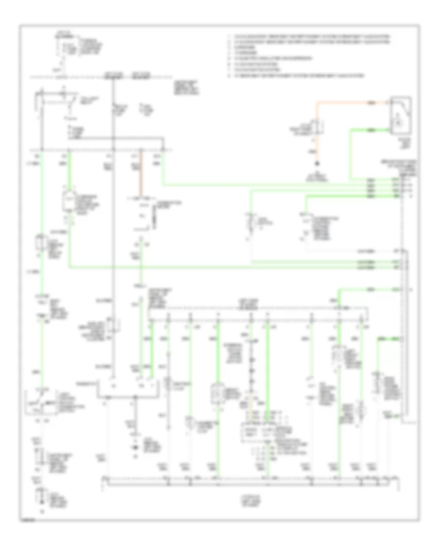
Instrument Illumination Wiring Diagram for Toyota Sequoia SR5 2006
List of elements for Instrument Illumination Wiring Diagram for Toyota Sequoia SR5 2006:
- (behind right side of instrument cluster)
- (left side of dash) j/c 39 & 40
- 10 speaker
- 6 speaker
- A j39
- A/c control (rear heater control panel)
- A10
- A17
- A20
- Alt fuse 140a
- Ashtray illum
- Back door power window control switch
- Body ecu (behind left end of dash)
- C10
- Cigarette lighter illum
- Combination meter
- D10
- E10
- E12
- E13
- Ecu-ig fuse 10a
- Fusible link block (in engine room j/b)
- Glove box light
- Gnd
- H11
- Head
- Height control switch
- Hot at all times
- Hot in on or start
- Ig (at right kick panel)
- Ign1 fuse 10a
- Ill+
- Ill+b
- Ill-
- Illumination
- Instrument panel j/b (behind left end of dash)
- Integration control & panel (behind center of dash)
- J/c 39 & 40 (left side of dash)
- J/c 43 right side of dash)
- J/c 8 (behind left end of dash)
- J/c 9 (behind left end of dash)
- J39
- J40
- Left front seat heater switch
- Light control switch (combination switch)
- Main switch
- Off
- Overhead module (on center front of roof)
- Panel fuse 7.5a
- R19
- R27
- R30
- Radio & player (w/o navigation) radio & player w/ display (w/ navigation)
- Rheostat
- Right front seat heater switch
- Steering switch (combi- nation switch)
- Sub j/b 3
- Sub j/b 3 (behind right side of instrument cluster)
- Swg
- Tail
- Taillight relay
- Trly
- W/ electric modulated air suspension
- W/ navigation system
- W/ rear seat entertainment system or rear seat audio system
- W/ sliding roof, rear seat entertainment system or rear seat audio system
- W/o navigation system
- W/o sliding roof, rear seat entertainment system & rear seat audio system
MEMORY SYSTEMS
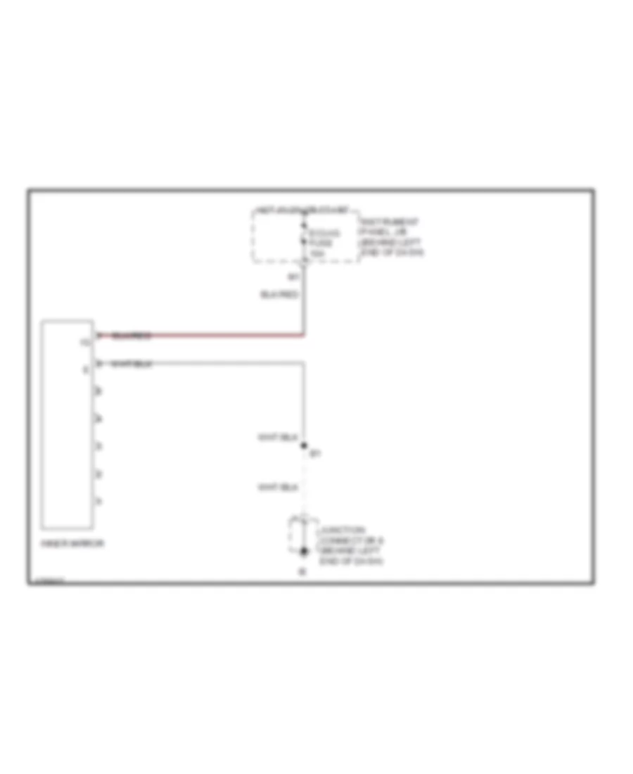
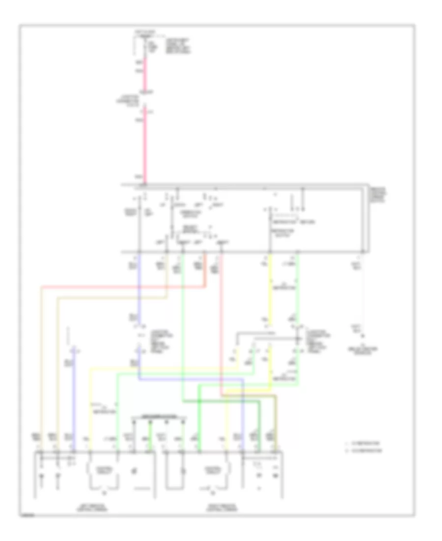
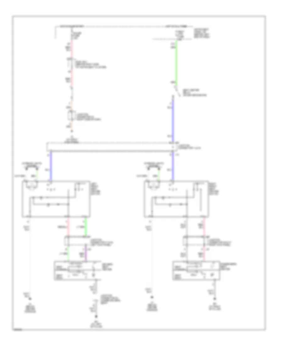
Memory Mirrors Wiring Diagram for Toyota Sequoia SR5 2006
List of elements for Memory Mirrors Wiring Diagram for Toyota Sequoia SR5 2006:
- (at left dash brace) if
- Acc
- Bdr
- Becu
- Body ecu (behind left end of dash)
- Cig fuse 15a
- Computer data lines system
- Control circuit
- Cpub
- Dcty
- Defogger system
- Dm+r
- Dmhr
- Dmvr
- Down
- Driver door ecu (in left front door)
- Driving position memory switch
- Dvc
- E20
- Ecu-b fuse 7.5a
- Ecu-ig fuse 10a
- Engine room j/b (on left side of engine compt)
- F17
- Front passenger door ecu (in right front door)
- G11
- Gnd
- Gnd1
- Heater
- Hot at all times
- Hot in on or acc
- Hot in on or start
- Hssr
- Ie (at left kick panel)
- Ig (at right kick panel)
- Im (below center console)
- Instrument panel j/b (behind left end of dash)
- J/c 12
- J/c 29 & 30 (left kick panel) j30
- J/c 37 & 38 (left side of dash)
- J/c 43 (right side of dash)
- J/c 6 & 7 (behind left kick panel)
- J/c 8 (behind left end of dash)
- J/c j14 & j15
- J14
- J15
- J29
- J37
- J38
- J6 d
- J7 f
- Ksw
- Left
- Left front door courtesy switch
- Left remote control mirror
- Lei
- Mirb
- Mire
- Mirs
- Mpx1
- Mpx2
- Pm+r
- Pmhr
- Pmvr
- Pnk
- Pvc
- Pwr 1 fuse 25a
- Pwr 2 fuse 25a
- Rad 2 fuse 7.5a
- Re1
- Remote control mirror switch
- Retraction
- Return
- Right
- Right remote control mirror
- Set
- Sig
- Sub j/b 3 (behind right side of instrument cluster)
- Unlock warning switch
- Vssr
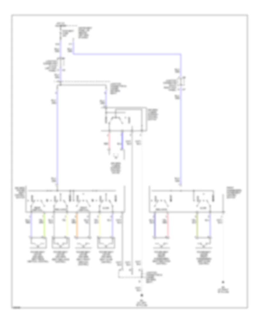
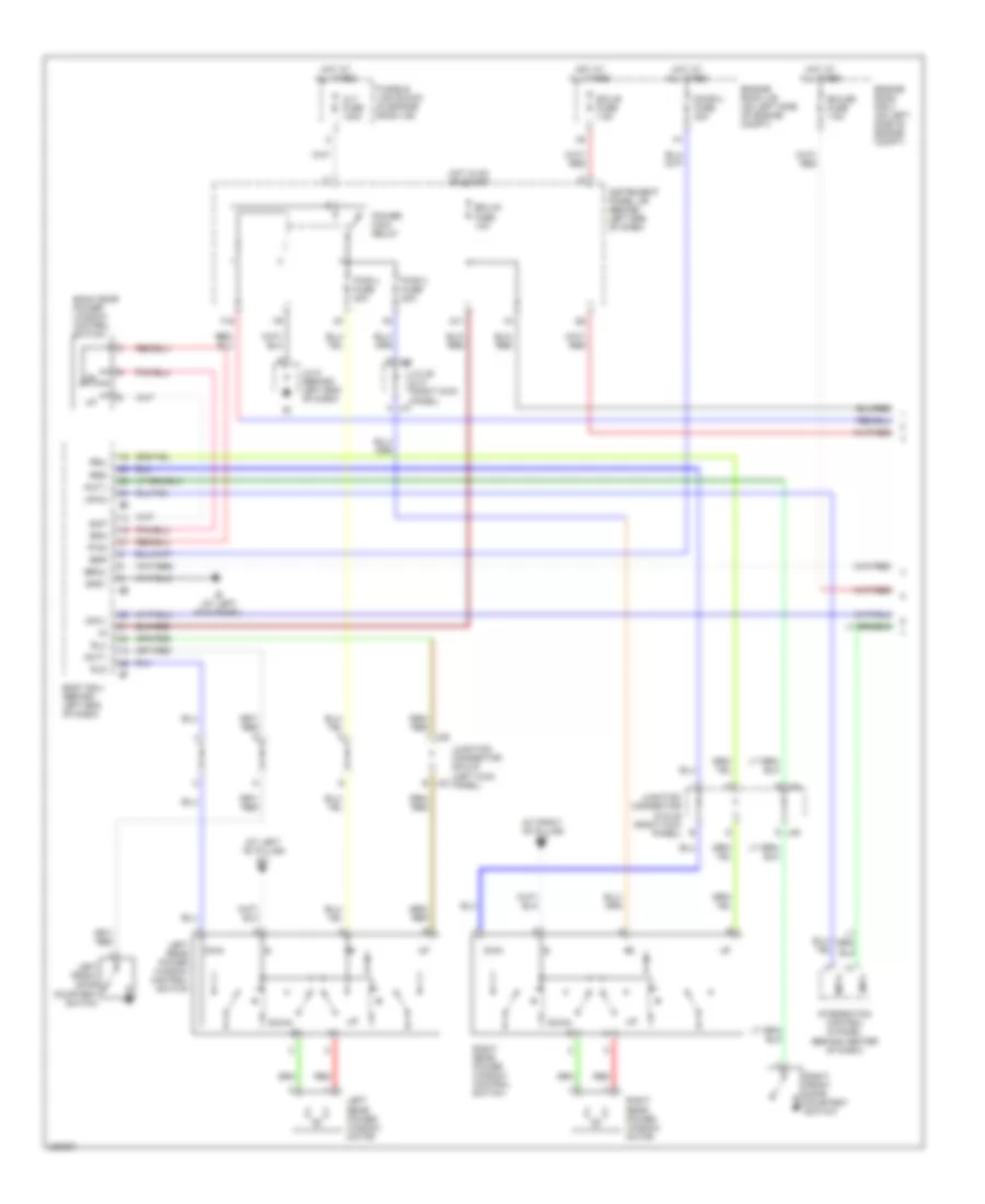
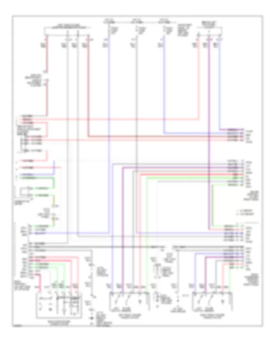
Memory Seat Wiring Diagram for Toyota Sequoia SR5 2006
List of elements for Memory Seat Wiring Diagram for Toyota Sequoia SR5 2006:
- A11
- Acc
- Becu
- Bh (at left "b" pillar)
- Body ecu (behind left end of dash)
- Computer data lines system
- Dcty
- Driver's lumbar support control motor
- Driver's lumbar support control switch
- Driving position memory switch
- Ecu-b fuse 7.5a
- Ecu-ig fuse 10a
- Engine room j/b (on left side of engine compt)
- Frv+
- Frv-
- G j29
- G j32
- G11
- G16
- Gnd
- Gnd1
- Hot at all times
- Hot in on or acc
- Hot in on or start
- Ie (at left kick panel)
- Ig (at right kick panel)
- Instrument panel j/b (behind left end of dash)
- J/c 24 (under driver's seat)
- J/c 29 & 30 (left kick panel)
- J/c 31 & 32 (left kick panel)
- J/c 33 & 34 (left kick panel)
- J/c 37 & 38 (left side of dash)
- J/c 43 (right side of dash)
- J/c 8 (behind left end of dash)
- J30 n
- J31
- J33
- J34
- J37
- J38
- Ksw
- Left front door courtesy switch
- Lft+
- Lft-
- Memory seat ecu & switch (side of left front seat)
- Mpx1
- Mpx2
- Pnk
- Power seat motor (driver's seat front vertical control)
- Power seat motor (driver's seat rear vertical control)
- Power seat motor (driver's seat reclining control)
- Power seat motor (driver's seat slide control)
- Pwr seat fuse 30a
- Radio 2 fuse 7.5a
- Rcl+
- Rcl-
- Red
- Sld+
- Sld-
- Sub j/b 3 (behind right side of instrument cluster)
- Sysb
- Unlock warning switch
POWER DISTRIBUTION
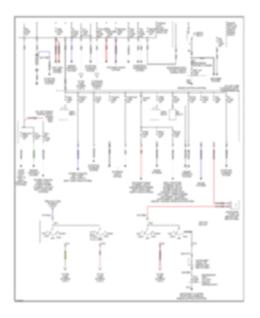
Power Distribution Wiring Diagram (1 of 3) for Toyota Sequoia SR5 2006
List of elements for Power Distribution Wiring Diagram (1 of 3) for Toyota Sequoia SR5 2006:
- (on left side of engine compt) engine room j/b
- (on left side of engine compt) engine room r/b 2
- A/ pump fuse 50a
- A/f fuse 20a
- Abs fuse 60a
- Acc
- Air conditioning system
- Air conditioning, interior lights, garage door opener, body computer, door locks systems
- Air sus fuse 50a
- Alt fuse 140a
- Alt-s fuse 7.5a
- Am1
- Am2
- Am2 fuse 25a
- Anti-lock brakes system
- Battery
- Cds fan fuse 25a
- Def i/up fuse 7.5a
- Defog fuse 40a
- Defog relay
- Defogger system
- Dome fuse 10a
- Door 2 fuse 30a
- Door locks, anti- theft & body computer systems
- Ecu- b2 fuse 7.5a
- Ecu-b fuse 7.5a
- Efi 1 fuse 20a
- Efi relay
- Electronic suspension system
- Engine controls system
- Engine room j/b (on left side of engine compt)
- Engine room r/b 2 (on left side of engine compt)
- Etcs fuse 10a
- Exterior lights system
- From am1 fuse (diagram 2 of 3)
- Fusible link block (in engine room j/b)
- Head relay
- Heater fuse 50a
- Horn fuse 10a
- Horn relay
- Ig1
- Ig2
- Ignition switch
- Instrument cluster, starting/charging & engine controls systems
- Instrument panel j/b (behind left end of dash)
- Lock
- Main fuse 40a
- Mir htr fuse 15a
- Nca
- Off
- Pnk
- Power windows, anti-theft, door locks, & body computer systems
- Power windows, door locks, wiper/washer, interior lights & body computer systems
- R/b fuse 30a
- Rad 1 fuse 20a
- Rad 3 fuse 30a
- Red
- Rr heater fuse 30a
- Run
- Security fuse 15a
- Short pin
- Sound systems
- St fuse 30a
- St2
- Sta fuse 7.5a
- Start
- Starting/ charging system
- To am1 fuse (diagram 2 of 3)
- To cig fuse (diagram 2 of 3)
- To engine room r/b 3 (diagram 3 of 3)
- To ign1 fuse (diagram 2 of 3)
- To wsh fuse (diagram 3 of 3)
- Towing fuse 30a
- Towing r/b fuse 60a
- Turn-haz fuse 20a
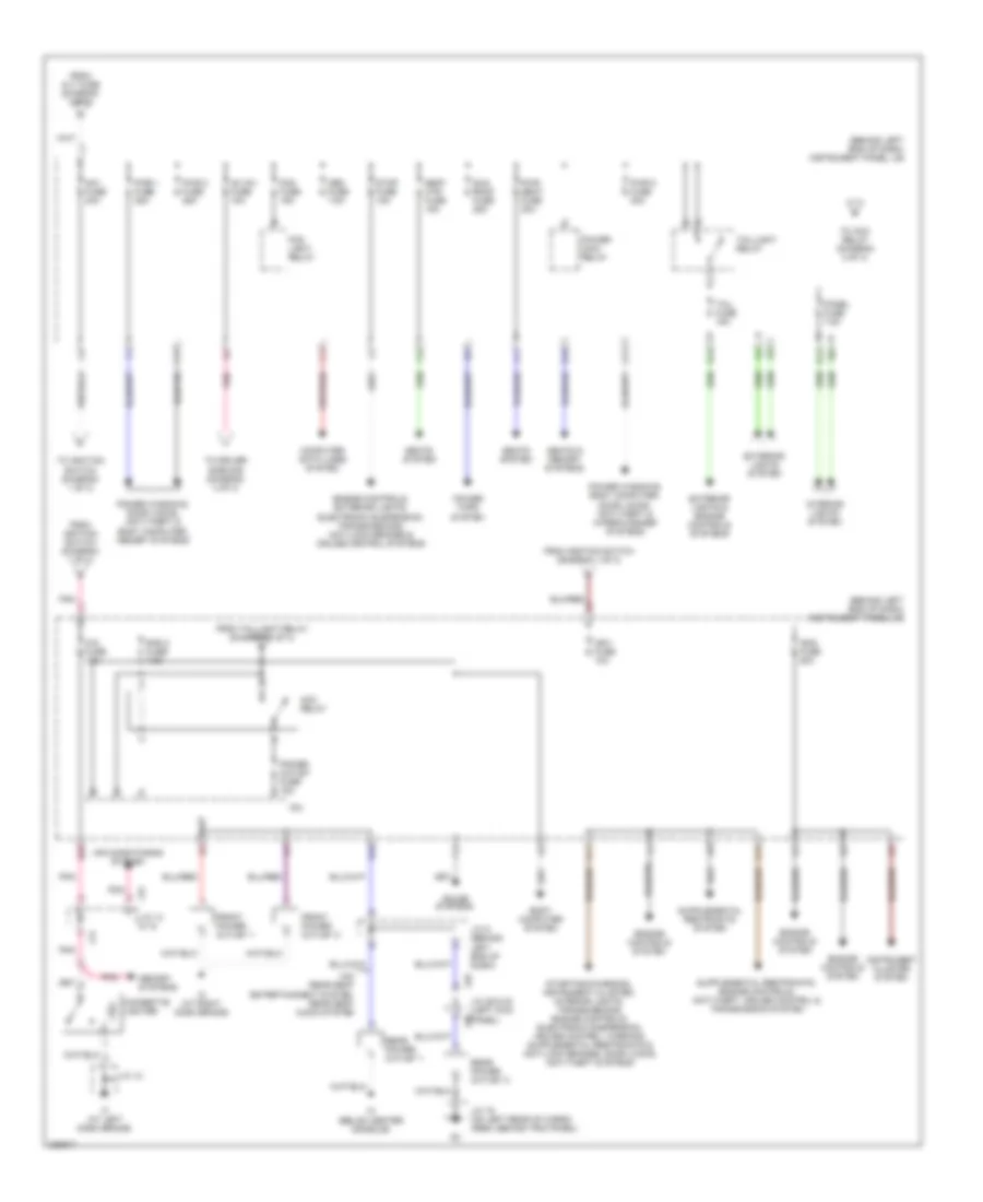
Power Distribution Wiring Diagram (2 of 3) for Toyota Sequoia SR5 2006
List of elements for Power Distribution Wiring Diagram (2 of 3) for Toyota Sequoia SR5 2006:
- (behind left end of dash) instrument panel j/b
- Ac inv fuse 15a
- Acc relay
- Air conditioning system
- Am1 fuse 40a
- Body computer system
- Cig fuse 15a
- Cigarette lighter
- Computer data lines system
- E10
- E12
- E17
- E18
- E20
- Engine controls system
- Engine controls, exterior lights, electronic suspension, transmissions, anti-lock brakes & cruise control systems
- Exterior lights & engine controls systems
- Exterior lights system
- F11
- F12
- F13
- F17
- F18
- Fog fuse 15a
- Fog light relay
- From alt fuse (diagram 1 of 3)
- From ignition switch (diagram 1 of 3)
- From taillight relay (diagram 2 of 3)
- Front power outlet 1
- Front power outlet 2
- G15
- G16
- H11
- If (at left dash brace)
- Ign1 fuse 10a
- Ign2 fuse 20a
- Im (below center console)
- Instrument cluster system
- Interior lights system
- Io (at right dash brace)
- Ipo
- J/c 12
- J/c 14 & 15
- J/c 19 (on left rear of cargo area, behind trim panel)
- J/c 29 & 30 (left kick panel)
- J/c 9 (behind left end of dash)
- J14
- J15
- J29
- J30
- Memory systems
- Obd fuse 7.5a
- Panel fuse 7.5a
- Pnk
- Power main relay
- Power outlet fuse 15a
- Power tops system
- Power windows, body computer, door locks, anti-theft & wiper/washer systems
- Power windows, door locks, anti-theft & body computer, memory systems
- Pwr 1 fuse 25a
- Pwr 2 fuse 25a
- Pwr 5 fuse 30a
- Pwr seat fuse 30a
- Rad 2 fuse 7.5a
- Rear power outlet 1
- Rear power outlet 2
- Seat htr fuse 15a
- Seats & memory systems
- Seats system
- Sound systems
- Stop fuse 15a
- Sun roof fuse 25a
- Tail fuse 15a
- Taillight relay
- To acc relay (diagram 2 of 3)
- To driver side r/b (diagram 3 of 3)
- To ignition switch (diagram 1 of 3)
- W/o rear seat entertainment system, rear seat audio system
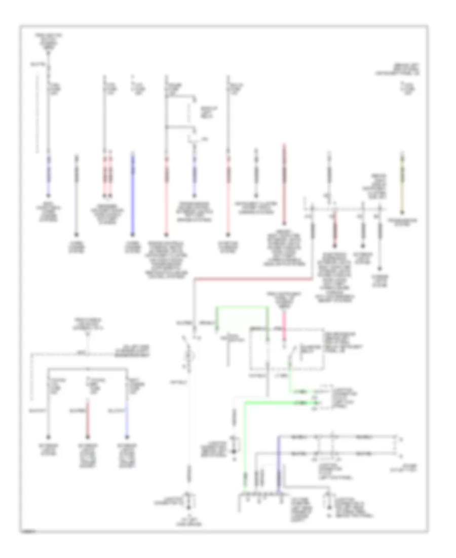
Power Distribution Wiring Diagram (3 of 3) for Toyota Sequoia SR5 2006
List of elements for Power Distribution Wiring Diagram (3 of 3) for Toyota Sequoia SR5 2006:
- (behind left end of dash) instrument panel j/b
- (behind right side of instrument cluster) sub j/b 3
- (on left side of engine compt) engine room r/b 3
- 4wd fuse 20a
- A18
- Ac1
- Ac2
- Back-up light relay
- Batt charge fuse 30a
- Body computer & wiper/ washer systems
- D11
- Defogger, air conditioning, door locks & anti-theft systems
- Driver side r/b (behind left end of dash, below instrument panel j/b)
- Ecu-ig fuse 10a
- Electronic suspension, exterior lights, body computer, interior lights, power windows, door locks, anti-theft, wiper/washer, warning, anti-lock brakes & memory systems
- Exterior lights system
- Exterior lights system (w/ 7 pin trailer socket)
- From fusible link block (diagram 1 of 3)
- From ignition switch (diagram 1 of 3)
- From instrument panel j/b (diagram 2 of 3)
- G10
- G11
- Gauge fuse 15a
- Htr fuse 10a
- If (at left dash brace)
- Instrument cluster, power tops & mirrors systems
- Interior lights system
- Inverter relay
- Ipo
- J31
- J32
- J33
- J34
- Junction connector 12
- Junction connector 19 (on left rear of cargo area, behind trim panel)
- Junction connector 31 & 32 (left kick panel)
- Junction connector 33 & 34 (left kick panel)
- Junction connector 8 (behind left end of dash)
- Main ind switch
- Memory, body computer, exterior lights, interior lights, power windows, door locks, anti-theft, wiper/washer & headlights systems
- Pnk
- Power outlet (115v)
- Starting/ charging system
- Towing brk fuse 30a
- Towing tail fuse 30a
- Transmissions system
- Transmissions, cruise control, exterior lights & anti-lock brakes systems
- Voltage inverter (left rear corner of luggage compt)
- Wip fuse 25a
- Wiper/ washer system
- Wsh fuse 25a
POWER DOOR LOCKS
Power Door Locks Wiring Diagram (1 of 3) for Toyota Sequoia SR5 2006
List of elements for Power Door Locks Wiring Diagram (1 of 3) for Toyota Sequoia SR5 2006:
- (behind left side of dash) (w/ anti-theft) glass breakage sensor microphone
- (inside of steering column) (w/ anti-theft) glass breakage sensor ecu
- Act+
- Act-
- Actd
- Bdr
- Becu
- Body ecu (behind left end of dash)
- Bzr
- Dcty
- Diode (interior light 1) (at base of right "b" pillar)
- Diode (interior light 2) (at base of left "b" pillar)
- Door 2 fuse 30a
- Dop
- Ecu-b fuse 7.5a
- Engine room j/b (on left side of engine compt)
- Engine room r/b 2 (on left side of engine compt)
- Exterior lights system
- Gb+b
- Gbig
- Gbs1
- Gnd
- Gnd1
- Hcty
- Headlights system
- Horns system
- Hot at all times
- Hot in on or start
- Hrly
- Htr fuse 10a
- Ie (at left kick panel)
- Ig (at right kick panel)
- Ind
- Instrument panel j/b (behind left end of dash)
- J29
- J44
- Junction connector (right side of dash)
- Junction connector 28 (near engine room j/b)
- Junction connector 29 & 30 (left kick j30 panel)
- Junction connector 44 & 45 (right kick j45 panel)
- Junction connector 8 (behind left end of dash)
- Ksw
- Left front door courtesy switch
- Left rear door courtesy switch
- Lswl
- Lswr
- Mi+
- Mi-
- Mic+
- Mic-
- Mpx1
- Mpx2
- Nca
- Pcty
- Pnk
- Prg
- Rda
- Right front door courtesy switch
- Right rear door courtesy switch
- Rlcy
- Rrcy
- S+b
- Security fuse 15a
- Sub j/b 3 (behind right side of instrument cluster)
- Sub j/b 4 (behind right side of instrument cluster)
- Theft deterrent horn (w/ anti- theft) (left side of engine compt)
- Trly
- Unlock warning switch
- Wireless door control receiver (w/ wireless door locks) (center of dash, below radio)
- Wireless door lock control buzzer (w/ wireless door locks) (on left front of engine compt, behind headlight)
Power Door Locks Wiring Diagram (2 of 3) for Toyota Sequoia SR5 2006
List of elements for Power Door Locks Wiring Diagram (2 of 3) for Toyota Sequoia SR5 2006:
- Bh (at left "b" pillar)
- Bk (at right "b" pillar)
- Combination meter
- Engine hood courtesy switch (on left center of radiator support)
- Instrument cluster system
- Instrument panel j/b (behind left end of dash)
- Integration control & panel (behind center of dash)
- J10
- J11
- J29
- J30
- J33
- J34
- J44
- J45
- Junction connector 1 (on right front of engine compt)
- Junction connector 10 & 11 (behind right end of dash)
- Junction connector 29 & 30 (left kick panel)
- Junction connector 33 & 34 (left kick panel)
- Junction connector 44 & 45 (right kick panel)
- Junction connector 8 (behind left end of dash)
- Left front door lock motor, door key lock/unlock switch & door unlock detection switch
- Left rear door lock motor & door unlock detection switch
- Mpx+
- Mpx-
- Right rear door lock motor & door unlock detection switch
- Security
Power Door Locks Wiring Diagram (3 of 3) for Toyota Sequoia SR5 2006
List of elements for Power Door Locks Wiring Diagram (3 of 3) for Toyota Sequoia SR5 2006:
- Act+
- Act-
- B10
- B11
- Back door courtesy switch
- Back door ecu (on left side of liftgate)
- Back door key lock & unlock switch
- Back door lock motor & back door unlock detection switch
- Bdcy
- Bdr
- Becu
- Bkl
- Bkul
- Cpub
- Ctye
- Driver door ecu (in left front door)
- Ecu-ig fuse 10a
- F17
- Front passenger door ecu (in right front door)
- G11
- G15
- Gnd
- Hot at all times
- Hot in run or start
- If (at left dash brace)
- Instrument panel j/b (behind left end of dash)
- J33
- J37
- J38
- Junction conn- ector 12
- Junction connector 19 (on left rear of cargo area, behind trim panel)
- Junction connector 22 (on left side of liftgate)
- Junction connector 33 & 34 (left kick j34 panel)
- Junction connector 37 & 38 (left side of dash)
- Junction connector 6 & 7 (behind left kick panel)
- Junction connector 8 (behind left end of dash)
- Keye
- Kul
- Lswb
- Lswd
- Lswe
- Lswp
- Mpx1
- Mpx2
- Pkl
- Pkul
- Pwr 1 fuse 25a
- Pwr 2 fuse 25a
- Pwr 5 fuse 30a
- Red
- Right front door lock motor, door key lock/unlock switch & door unlock detection switch
- Sig
- Sub j/b 3 (behind right side of instrument cluster)
- W/ memory
- W/o memory
POWER MIRRORS
Electrochromic Mirror Wiring Diagram for Toyota Sequoia SR5 2006
List of elements for Electrochromic Mirror Wiring Diagram for Toyota Sequoia SR5 2006:
- Ecu-ig fuse 10a
- Hot in on or start
- Inner mirror
- Instrument panel j/b (behind left end of dash)
- Junction connector 8 (behind left end of dash)
Power Mirrors Wiring Diagram for Toyota Sequoia SR5 2006
List of elements for Power Mirrors Wiring Diagram for Toyota Sequoia SR5 2006:
- A j7
- C j6
- Cig fuse 15a
- Control circuit
- Defogger system
- Down
- Down/ right
- E20
- Hot in acc or on
- Im (below center console)
- Instrument panel j/b (behind left end of dash)
- J14
- J15
- J6 b
- J7 b
- Junction connector 14 & 15
- Junction connector 6 & 7 (behind left kick panel)
- Left
- Left remote control mirror
- Operation switch
- Pnk
- Remote control mirror switch
- Retraction
- Retractor switch
- Return
- Right
- Right remote control mirror
- Select switch
- Up/ left
- W/ retractor
- W/o retractor
POWER SEATS
Heated Seats Wiring Diagram for Toyota Sequoia SR5 2006
List of elements for Heated Seats Wiring Diagram for Toyota Sequoia SR5 2006:
- A15
- Bh (at left "b" pillar)
- Bk (at right "b" pillar)
- Driver's seat heater
- F18
- Gauge fuse 15a
- Hot at all times
- Hot in on or start
- Ig (at right kick panel)
- Im (below center console)
- Instrument panel j/b (behind left end of dash)
- Interior lights system
- J14
- J15
- J31
- J32
- J46
- J47
- Junction connector 14 & 15
- Junction connector 24 (under driver's seat)
- Junction connector 31 & 32 (left kick panel)
- Junction connector 43 (right side of dash)
- Junction connector 46 & 47 (right kick panel)
- Left front seat heater switch
- Passenger's seat heater
- Right front seat heater switch
- Seat back
- Seat cushion
- Seat heater relay (on driver side r/b)
- Seat htr fuse 15a
- Sub j/b 3 (behind right side of instrument cluster)
Power & Lumbar Seat Wiring Diagram for Toyota Sequoia SR5 2006
List of elements for Power & Lumbar Seat Wiring Diagram for Toyota Sequoia SR5 2006:
- Bh (at left "b" pillar)
- Bk (at right "b" pillar)
- C j31
- Down
- Driver's lumbar support control motor
- Driver's lumbar support control switch
- Driver's power seat control switch
- F11
- Front
- Front passenger's power seat control switch
- Front vertical
- G j32
- G j47
- G16
- Hot at all times
- Instrument panel j/b (behind left end of dash)
- J46 c
- Junction connector 24 (under driver's seat)
- Junction connector 31 & 32 (left kick panel)
- Junction connector 46 & 47 (right kick panel)
- Power seat motor (driver's
- Power seat motor (driver's seat rear vertical control)
- Power seat motor (front passenger's seat reclining control)
- Power seat motor (front passenger's seat slide control)
- Pwr seat fuse 30a
- Rear
- Rear vertical
- Reclining
- Red
- Seat front vertical control)
- Seat reclining control)
- Seat slide control)
- Slide
POWER TOP/SUNROOF
Power Top/Sunroof Wiring Diagram for Toyota Sequoia SR5 2006
List of elements for Power Top/Sunroof Wiring Diagram for Toyota Sequoia SR5 2006:
- (in body
- Body ecu (behind left end of dash)
- Close
- Cls
- Dcty
- Down
- Ecu-ig fuse 10a
- F10
- G j29
- G12
- Harness, at center of windshield header)
- Hot at all times
- Hot in on or start
- Instrument panel j/b (behind left end of dash)
- J/c 29 & 30 left kick panel)
- J/c 44 & 45 (right kick panel) n
- J/c 8 (behind left end of dash)
- J44
- J45
- Left front door courtesy switch
- Moon roof control switch
- Mpx1
- Mpx3
- N j30
- Open
- Opn
- Overhead module (on center front of roof)
- Pcty
- Psw1
- Psw2
- Pswe
- Right front door courtesy switch
- Sliding roof control ecu (on center front of roof)
- Sun roof fuse 25a
POWER WINDOWS
Power Windows Wiring Diagram (1 of 2) for Toyota Sequoia SR5 2006
List of elements for Power Windows Wiring Diagram (1 of 2) for Toyota Sequoia SR5 2006:
- (at left ``b" pillar) bh
- (at right ``b" pillar) bk
- A j47
- Alt fuse 140a
- Back door power window control switch
- Bdn
- Bdr
- Becu
- Body ecu (behind left end of dash)
- Bup
- Dcty
- Door 2 fuse 30a
- Down
- Dwn
- E j46
- Ecu-b fuse 7.5a
- Ecu-b2 fuse 7.5a
- Ecu-ig fuse 10a
- Engine room j/b (on left side of engine compt)
- Engine room r/b 2 (on left side of engine compt)
- F16
- Fusible link block (in engine room j/b)
- G11
- Gnd1
- Hot at all times
- Hot in on or start
- Ie (at left kick panel)
- Instrument panel j/b (behind left end of dash)
- Integration control & panel (behind center of dash)
- J/c 46 & 47 (right kick panel)
- J/c 8 (behind left end of dash)
- J29 i
- J30 b
- J44 n
- J45 g
- Junction connector 29 & 30 (left kick panel)
- Junction connector 44 & 45 (right kick panel)
- Left front door courtesy switch
- Left rear power window control switch
- Left rear power window motor
- Mpx+
- Mpx-
- Mpx1
- Mpx2
- Pcty
- Power main relay
- Pwr 3 fuse 20a
- Pwr 4 fuse 20a
- Pws
- Red
- Right front door courtesy switch
- Right rear power window control switch
- Right rear power window motor
- Rld
- Rlu
- Rrd
- Rru
Power Windows Wiring Diagram (2 of 2) for Toyota Sequoia SR5 2006
List of elements for Power Windows Wiring Diagram (2 of 2) for Toyota Sequoia SR5 2006:
- (behind left kick panel) j/c 6 & 7
- (behind right side of instrument cluster) sub j/b 3
- (left side of dash) junction connector 37 & 38
- B10
- B11
- Back door ecu (on left side of liftgate)
- Back door power window motor
- Bddn
- Bdr
- Bdup
- Becu
- Combination meter
- Cpub
- Ddn
- Driver door ecu (in left front door)
- Ds2
- Dsg
- Dsi
- Dsv
- F17
- Front passenger door ecu (in right front door)
- G15
- Gnd
- H j33
- Hot at all times
- If (at left dash brace)
- Instrument panel j/b (behind left end of dash)
- J/c 12
- J/c 19 (on left rear of cargo area, behind trim panel)
- J/c 22 (on left side of liftgate)
- J/c 33 & 34 (left kick panel)
- J/c 6 & 7 (behind left kick panel)
- J/c 8 (behind left end of dash)
- J33
- J34
- J34 b
- J37 a
- J38 a
- J6 d
- J6 e
- J7 e
- J7 f
- Left front power window motor
- Limit switch
- Lmt
- Lsw
- Mpx1
- Mpx2
- Pdn
- Pls
- Pls1
- Pls2
- Pnk
- Pulse sensor
- Pwr 1 fuse 25a
- Pwr 2 fuse 25a
- Pwr 5 fuse 30a
- Red
- Right front power window motor
- Sgnd
- Sig
- Ssrb
- Sub j/b 3 (behind right side of instrument cluster)
- W/ memory
- W/o memory
- Wlsw
RADIO
10-Speaker System Wiring Diagram, with Rear Entertainment with Navigation (1 of 3) for Toyota Sequoia SR5 2006
List of elements for 10-Speaker System Wiring Diagram, with Rear Entertainment with Navigation (1 of 3) for Toyota Sequoia SR5 2006:
- (behind left center of dash) j/c 17
- (behind left side of dash, on parking brake lever) parking brake switch
- (behind right center of dash) antenna amplifier
- (behind right end of dash) j/c 51 & 52
- (left kick panel) acc cut relay
- A12
- A15
- Acc
- Accr
- Ant
- Atx+
- Atx-
- Au1
- Au2
- Cdl+
- Cdl-
- Cdr+
- Cdr-
- Combination meter
- Csld
- Eau
- Ecu-b fuse 7.5a
- Engine control module (behind right side of dash)
- Engine room j/b (on left side of engine compartment)
- F12
- Gauge fuse 15a
- Gnd
- H11
- Hot at all times
- Hot in acc or on
- Hot in on or start
- Ign1 fuse 10a
- Ill+
- Ill-
- Instrument panel j/b (behind left end of dash)
- Interior lights system
- Io (at right dash brace)
- Ipo
- Ivo+
- Ivo-
- J/c 37 & 38 (left side of dash) j38
- J/c 8 (behind left end of dash)
- J37
- J51
- J52
- Mode
- Mute
- Nca
- Ntsc
- Park/neutral position switch (on transmission)
- Pkb
- Pnk
- R-l+
- R-l-
- R-r+
- R-r-
- R26
- R27
- R28
- R29
- R30
- Rad 1 fuse 20a
- Rad 2 fuse 7.5a
- Radio & player w/ display
- Red
- Rev
- Rmut
- Rsld
- Seek+
- Seek-
- Sgd1
- Sgnd
- Sld
- Sld1
- Spd
- Speedo- meter
- Spiral cable
- Steering switch (combination switch)
- Sub j/b 3 (behind right side of instrument cluster)
- Sub j/b 4 (behind right side of instrument cluster)
- Sw1
- Sw2
- Swg
- Tx+
- Tx-
- Vehicle speed sensor (combination meter)
- Vol+
- Vol-
10-Speaker System Wiring Diagram, with Rear Entertainment with Navigation (2 of 3) for Toyota Sequoia SR5 2006
List of elements for 10-Speaker System Wiring Diagram, with Rear Entertainment with Navigation (2 of 3) for Toyota Sequoia SR5 2006:
- (center of dash, below radio) stereo component amplifier
- Acc
- B2+
- Engine room r/b 2 (on left side of engine compartment)
- Engine room room j/b (on left side of engine compartment)
- Fl+
- Fl-
- Fr+
- Fr-
- Gnd
- Hot at all times
- Int+
- Int-
- Io (at right dash brace)
- J/c 10 & 11 (behind right end of dash)
- J/c 33 & 34 (left kick panel)
- J/c 48 & 49 (right kick panel)
- J10
- J11
- J33
- J34
- J48
- J49
- Left front door speaker & woofer
- Left rear door speaker
- Left tweeter
- Mute
- Nca
- Pnk
- Rad 3 fuse 30a
- Red
- Right front door speaker & woofer
- Right rear door speaker
- Right tweeter
- Rl+
- Rl-
- Rr+
- Rr-
- Rse fuse 7.5a
- S10
- Sgnd
- Tx+
- Tx-
- Wfl+
- Wfl-
- Wfr+
- Wfr-
10-Speaker System Wiring Diagram, with Rear Entertainment with Navigation (3 of 3) for Toyota Sequoia SR5 2006
List of elements for 10-Speaker System Wiring Diagram, with Rear Entertainment with Navigation (3 of 3) for Toyota Sequoia SR5 2006:
- +b1
- +b2
- Acc
- Acc2
- Acc3
- Al+
- Al-
- Ar+
- Ar-
- Auxl
- Auxr
- Bu+b
- Dgnd
- Dvd player
- Gaux
- Gnd
- Gnd1
- Gnd4
- Hp1l
- Hp1r
- Hp2l
- Hp2r
- Hpl
- Hpl+
- Hpl-
- Hpr
- Hpr+
- Hpr-
- Im (below center console)
- Left headphone terminal
- Lmut
- Mute
- Nca
- Nts1
- Nts2
- Nts4
- Ntsc
- R-l+
- R-l-
- R-r+
- R-r-
- R21
- R22
- R23
- Rear seat entertainment display
- Rear seat entertainment ecu (under rear of center console)
- Red
- Right headphone terminal
- Rmut
- Sg1
- Sg2
- Sg3
- Sg4
- Sg5
- Sg6
- Sg7
- Sg9
- Sgn1
- Sgn2
- Sgn5
- Sgnd
- Sld
- Sld1
- Syn2
- Sync
- Tx+
- Tx-
- Tx2+
- Tx2-
- Tx3+
- Tx3-
- Vg2
- Video terminal
- Vr2
10-Speaker System Wiring Diagram, with Rear Entertainment without Navigation (1 of 3) for Toyota Sequoia SR5 2006
List of elements for 10-Speaker System Wiring Diagram, with Rear Entertainment without Navigation (1 of 3) for Toyota Sequoia SR5 2006:
- (left kick panel) acc cut relay
- A12
- Acc+b
- Accr
- Ant+b
- Antenna amplifier (behind right center of dash)
- Au1
- Au2
- Bu+b
- Eau
- Ecu-b fuse 7.5a
- Engine control module (behind right side of dash)
- Engine room j/b (on left side of engine compartment)
- Engine room r/b 2 (on left side of engine compartment)
- F12
- Gnd
- Hot at all times
- Hot in on or acc
- Ill+
- Ill-
- Instrument panel j/b (behind left end of dash)
- Interior lights system
- Io (at right dash brace)
- J/c 37 & 38 (left side of dash)
- J37
- J38
- Mode
- Mute
- Nca
- Pnk
- R19
- R20
- Rad 1 fuse 20a
- Rad 2 fuse 7.5a
- Rad 3 fuse 30a
- Radio & player
- Red
- Rmu
- Rse fuse 7.5a
- Rsl+
- Rsl-
- Rsr+
- Rsr-
- S-gnd
- Seek+
- Seek-
- Sld1
- Spiral cable
- Steering switch (combination switch)
- Sub j/b 3 (behind right side of instrument cluster)
- Sw1
- Sw2
- Tx+
- Tx-
- Tx1+
- Tx1-
- Vol+
- Vol-
10-Speaker System Wiring Diagram, with Rear Entertainment without Navigation (2 of 3) for Toyota Sequoia SR5 2006
List of elements for 10-Speaker System Wiring Diagram, with Rear Entertainment without Navigation (2 of 3) for Toyota Sequoia SR5 2006:
- (at right dash brace)
- (below center console)
- Acc
- B2+
- Fl+
- Fl-
- Fr+
- Fr-
- Gnd
- I j34
- J/c 10 & 11 (behind right end of dash)
- J/c 33 & 34 (left kick panel)
- J/c 48 & 49 (right kick panel)
- J10
- J11
- J33
- J48
- J49
- Left front door speaker & woofer
- Left rear door speaker
- Left tweeter
- Mute
- Nca
- Pnk
- Red
- Right front door speaker & woofer
- Right rear door speaker
- Right tweeter
- Rl+
- Rl-
- Rr+
- Rr-
- S10
- Sgnd
- Stereo component amplifier (center of dash, below radio)
- Tx+
- Tx-
- Wfl+
- Wfl-
- Wfr+
- Wfr-
10-Speaker System Wiring Diagram, with Rear Entertainment without Navigation (3 of 3) for Toyota Sequoia SR5 2006
List of elements for 10-Speaker System Wiring Diagram, with Rear Entertainment without Navigation (3 of 3) for Toyota Sequoia SR5 2006:
- +b1
- +b2
- Acc
- Acc2
- Acc3
- Al+
- Al-
- Ar+
- Ar-
- Auxl
- Auxr
- Bu+b
- Dgnd
- Dvd player
- Gaux
- Gnd
- Gnd1
- Gnd4
- Hp1l
- Hp1r
- Hp2l
- Hp2r
- Hpl
- Hpl+
- Hpl-
- Hpr
- Hpr+
- Hpr-
- Left headphone terminal
- Lmut
- Mute
- Nca
- Nts2
- Nts4
- Ntsc
- R-l+
- R-l-
- R-r+
- R-r-
- R21
- R22
- R23
- Rear seat entertainment display
- Rear seat entertainment ecu (under rear of center console)
- Red
- Right headphone terminal
- Rmut
- Sg1
- Sg2
- Sg4
- Sg5
- Sg6
- Sg7
- Sg9
- Sgn2
- Sgn5
- Sgnd
- Sld
- Sld1
- Syn2
- Sync
- Tx+
- Tx-
- Tx2+
- Tx2-
- Tx3+
- Tx3-
- Vg2
- Video terminal
- Vr2
10-Speaker System Wiring Diagram, without Rear Entertainment with Navigation (1 of 2) for Toyota Sequoia SR5 2006
List of elements for 10-Speaker System Wiring Diagram, without Rear Entertainment with Navigation (1 of 2) for Toyota Sequoia SR5 2006:
- (behind
- (behind right end of dash) j/c 51 & 52
- (left kick panel) acc cut relay
- A12
- A15
- Acc
- Accr
- Ant
- Antenna amplifier (behind right center of dash)
- Atx+
- Atx-
- Au1
- Au2
- Cluster)
- Combination meter
- Eau
- Ecu-b fuse 7.5a
- Engine control module (behind right side of dash)
- Engine room j/b (on left side of engine compartment)
- Engine room r/b 2 (on left side of engine compartment)
- F j33
- F12
- Gauge fuse 15a
- Gnd
- H11
- Hot at all times
- Hot in acc or on
- Hot in on start
- Ign1 fuse 10a
- Ill+
- Ill-
- Instrument
- Instrument panel j/b (behind left end of dash)
- Interior lights system
- Io (at right dash brace)
- Ipo
- Ivo+
- Ivo-
- J/c 17 (behind left center of dash)
- J/c 33 & 34 (left kick panel)
- J/c 37 & 38 (left side of dash) j38
- J/c 8 (behind left end of dash)
- J34 l
- J37
- J51
- J52
- Left rear door speaker
- Mode
- Mute
- Nca
- Park/neutral position switch (on transmission)
- Pnk
- R-l+
- R-l-
- R-r+
- R-r-
- R27
- R29
- R30
- Rad 1 fuse 20a
- Rad 2 fuse 7.5a
- Radio & player w/ display
- Red
- Rev
- Right
- Rmut
- Rse fuse 7.5a
- Rsld
- Seek+
- Seek-
- Side of
- Sld
- Sld1
- Spd
- Speedo- meter
- Spiral cable
- Steering switch (combination switch)
- Sub j/b 3
- Sub j/b 3 (behind
- Sw1
- Sw2
- Swg
- Tx+
- Tx-
- Vehicle speed sensor (combination meter)
- Vol+
- Vol-
10-Speaker System Wiring Diagram, without Rear Entertainment with Navigation (2 of 2) for Toyota Sequoia SR5 2006
List of elements for 10-Speaker System Wiring Diagram, without Rear Entertainment with Navigation (2 of 2) for Toyota Sequoia SR5 2006:
- (center of dash, below radio)
- (on center of roof, under headliner) (if equipped) rear seat audio controller
- Acc
- B j10
- B j11
- B2+
- Engine room j/b (on left side of engine compartment)
- Fl+
- Fl-
- Fr+
- Fr-
- Gnd
- Hot at all times
- Hp1l
- Hp1r
- Hp2l
- Hp2r
- Hpl
- Hpr
- Im (below center console)
- Int+
- Int-
- Io (at right dash brace)
- J/c 10 & 11 (behind right end of dash)
- J/c 48 & 49 (right kick panel)
- J48
- J49 h
- Left front door speaker & woofer
- Left headphone terminal
- Left tweeter
- Mute
- Nca
- Pnk
- R-l+
- R-l-
- R-r+
- R-r-
- Rad 3 fuse 30a
- Red
- Right front door speaker & woofer
- Right headphone terminal
- Right rear door speaker
- Right tweeter
- Rl+
- Rl-
- Rmut
- Rr+
- Rr-
- S10
- Sg1
- Sgn1
- Sgn2
- Sgnd
- Stereo component amplifier
- Tx+
- Tx-
- Wfl+
- Wfl-
- Wfr+
- Wfr-
10-Speaker System Wiring Diagram, without Rear Entertainment without Navigation (1 of 2) for Toyota Sequoia SR5 2006
List of elements for 10-Speaker System Wiring Diagram, without Rear Entertainment without Navigation (1 of 2) for Toyota Sequoia SR5 2006:
- (behind
- (left kick panel) acc cut relay
- A12
- Acc+b
- Accr
- Ant+b
- Antenna amplifier (behind right center of dash)
- Au1
- Au2
- Bu+b
- Cluster)
- Eau
- Ecu-b fuse 7.5a
- Engine control module (behind right side of dash)
- Engine room j/b (on left side of engine compartment)
- Engine room r/b 2 (on left side of engine compartment)
- F j33
- F12
- Gnd
- Hot at all times
- Hot in acc or on
- Ill+
- Ill-
- Instrument
- Instrument panel j/b (behind left end of dash)
- Interior lights system
- Io (at right dash brace)
- J/c 33 & 34 (left kick panel)
- J/c 37 & 38 (left side of dash)
- J34 l
- J37
- J38
- Left rear door speaker
- Mode
- Mute
- Nca
- Pnk
- R19
- Rad 1 fuse 20a
- Rad 2 fuse 7.5a
- Radio & player
- Red
- Right
- Rmu
- Rse fuse 7.5a
- Rsl+
- Rsl-
- Rsr+
- Rsr-
- Seek+
- Seek-
- Side of
- Sld1
- Spiral cable
- Steering switch (combination switch)
- Sub j/b 3
- Sw1
- Sw2
- Tx+
- Tx-
- Tx1+
- Tx1-
- Vol+
- Vol-
10-Speaker System Wiring Diagram, without Rear Entertainment without Navigation (2 of 2) for Toyota Sequoia SR5 2006
List of elements for 10-Speaker System Wiring Diagram, without Rear Entertainment without Navigation (2 of 2) for Toyota Sequoia SR5 2006:
- (center of dash, below radio)
- (on center of roof, under headliner) (if equipped) rear seat audio controller
- Acc
- B j11
- B2+
- Engine room j/b (on left side of engine compartment)
- Fl+
- Fl-
- Fr+
- Fr-
- Gnd
- Hot at all times
- Hp1l
- Hp1r
- Hp2l
- Hp2r
- Hpl
- Hpr
- Im (below center console)
- Io (at right dash brace)
- J/c 10 & 11 (behind right end of dash)
- J/c 48 & 49 (right kick panel)
- J48
- J49 h
- Left front door speaker & woofer
- Left headphone terminal
- Left tweeter
- Mute
- Nca
- Pnk
- R-l+
- R-l-
- R-r+
- R-r-
- Rad 3 fuse 30a
- Red
- Right front door speaker & woofer
- Right headphone terminal
- Right rear door speaker
- Right tweeter
- Rl+
- Rl-
- Rmut
- Rr+
- Rr-
- S10
- Sg1
- Sgn1
- Sgn2
- Sgnd
- Stereo component amplifier
- Tx+
- Tx-
- Wfl+
- Wfl-
- Wfr+
- Wfr-
6-Speaker System Wiring Diagram for Toyota Sequoia SR5 2006
List of elements for 6-Speaker System Wiring Diagram for Toyota Sequoia SR5 2006:
- A12
- Acc cut relay (left kick panel)
- Acc+b
- Accr
- Ant+b
- Antenna amplifier
- Au1
- Au2
- Bu+b
- Eau
- Ecu-b fuse 7.5a
- Engine control module (behind right side of dash)
- Engine room j/b (on left side of engine compt)
- F12
- Fl+
- Fl-
- Fr+
- Fr-
- Gnd
- Hot at all times
- Hot in acc or on
- If (at left dash brace)
- Ill+
- Ill-
- Instrument panel j/b (behind left end of dash)
- Interior lights system
- J/c 12
- J33
- J34
- J37
- J38
- J48
- J49
- Junction connector 33 & 34 (left kick panel)
- Junction connector 37 & 38 (left side of dash)
- Junction connector 48 & 49 (right kick panel)
- Left front door speaker
- Left rear door speaker
- Left tweeter
- Mode
- Pnk
- R19
- Rad 1 fuse 20a
- Rad 2 fuse 7.5a
- Radio & player
- Red
- Right front door speaker
- Right rear door speaker
- Right tweeter
- Rl+
- Rl-
- Rr+
- Rr-
- Seek+
- Seek-
- Spiral cable
- Steering switch (combination switch)
- Sub j/b 3 (behind right side of instrument cluster)
- Sw1
- Sw2
- Vol+
- Vol-
STARTING/CHARGING
Charging Wiring Diagram for Toyota Sequoia SR5 2006
List of elements for Charging Wiring Diagram for Toyota Sequoia SR5 2006:
- Alt fuse 140a
- Alt-s fuse 7.5a
- Battery
- Battery ground
- Charge indication
- Combination meter
- Ecu-ig fuse 10a
- Engine room j/b (on left side of engine compt)
- Fusible link block (in engine room j/b)
- Generator
- H11
- Hot in on or start
- Ign1 fuse 10a
- Instrument panel j/b (behind left end of dash)
- K11
- Nca
- Starting circuit
Starting Wiring Diagram for Toyota Sequoia SR5 2006
List of elements for Starting Wiring Diagram for Toyota Sequoia SR5 2006:
- A19
- Acc
- Am2 fuse 25a
- Battery
- Battery ground
- Engine control module (behind right side of dash)
- Engine room j/b (on left side of engine compartment)
- Engine room r/b 2 (on left side of engine compt)
- Fusible link block (in engine room j/b)
- Ignition switch
- Instrument panel j/b (behind left end of dash)
- J51 b
- J52
- Junction connector 2 (on left side of engine compartment, near engine room j/b)
- Junction connector 5 (on left side of engine compartment, near engine room j/b)
- Junction connector 51 & 52 (behind right end of dash)
- Lock
- Nca
- Off
- Park/ neutral position switch (on transmission)
- St fuse 30a
- Sta
- Sta fuse 7.5a
- Star/nsw
- Start
- Starter
- Starter relay
- Stsw
- Sub j/b 4 (behind right side of instrument cluster)
SUPPLEMENTAL RESTRAINTS
Supplemental Restraints Wiring Diagram (1 of 2) for Toyota Sequoia SR5 2006
List of elements for Supplemental Restraints Wiring Diagram (1 of 2) for Toyota Sequoia SR5 2006:
- (behind center of dash) integration control & panel
- (behind left end of dash) body ecu
- (behind left end of dash) instrument panel j/b
- (front passenger air bag assembly) air bag squib
- +sl
- +sr
- -sl
- -sr
- A10
- A19
- A20
- A21
- Air bag sensor assembly (below front of center console)
- Air bag squib (steering wheel pad)
- D2+
- D2-
- E14
- Engine control module (behind right side of dash)
- Escl
- Escr
- Esl
- Esr
- F/ps
- F15
- Fsr+
- Fsr-
- Gsw
- Gsw2
- Icl+
- Icl-
- Icr+
- Icr-
- Ig+
- Ig2
- Lbe+
- Lbe-
- Left curtain air bag squib (left "c" pillar)
- Left pretensioner (at base of left "b" pillar, behind trim panel)
- Left rear side air bag sensor (w/ side air bag) (left rear "c' pillar)
- Left side air bag sensor (w/ side air bag) (at base of right "b" pillar, behind trim panel)
- Left side air bag squib (w/ side air bag)
- Lsp+
- Lsp-
- P-ab
- P2+
- P2-
- Paon
- Pbew
- Pl+
- Pl-
- Pr+
- Pr-
- Red
- Right curtain air bag squib (right "c" pillar)
- Right pretensioner (at base of right "b" pillar, behind trim panel)
- Right rear side air bag sensor (w/ side air bag) (left "c" pillar)
- Right side air bag sensor (w/ side air bag) (at base of right "b" pillar, behind trim panel)
- Right side air bag squib (w/ side air bag)
- Rmil
- Rmsw
- Sfl+
- Sfl-
- Sfr+
- Sfr-
- Sil
- Vucl
- Vucr
- Vupl
- Vupr
Supplemental Restraints Wiring Diagram (2 of 2) for Toyota Sequoia SR5 2006
List of elements for Supplemental Restraints Wiring Diagram (2 of 2) for Toyota Sequoia SR5 2006:
- (behind right side of instrument cluster) sub j/b 3
- (behind right side of instrument cluster) sub j/b 4
- (right kick panel)
- +sl
- +sr
- -sl
- -sr
- A/b
- A10
- A15
- A20
- B10
- Bgnd
- Bk (at right "b" pillar)
- Bsw
- Buckle switch
- C j49
- Combination meter
- Data link connector (dlc) 3 (right of steering column)
- Dia
- E17
- Ecu-b fuse 7.5a
- Engine room j/b (on left side of engine compt)
- F10
- Fsr+
- Fsr-
- Gauge fuse 15a
- Gnd
- H11
- Hot in on or start
- Ie (left kick panel)
- Ign1 fuse 10a
- Instrument panel j/b (behind left end of dash)
- J44
- J45 b
- J48 i
- Junction connector 43 (right side of dash)
- Junction connector 44 & 45 (right kick panel)
- Junction connector 48 & 49 (right kick panel)
- Junction connector 8 (behind left end of dash)
- Left front air bag sensor (on left front of radiator support)
- Left front occupant classification sensor (under front passenger seat)
- Left rear occupant classification sensor (under front passenger seat)
- Left seat buckle switch & position air bag sensor (under driver's seat)
- Occupant classification ecu (under right front seat)
- Pnk
- Red
- Right buckle switch
- Right front air bag sensor (on right side of radiator support)
- Right front occupant classification sensor (under front passenger seat)
- Right rear occupant classification sensor (under front passenger seat)
- Roll sensing of curtain shield air bag cutoff switch
- Rsca off ind
- Seat position air bag sensor
- Sgd1
- Sgd2
- Sgd3
- Sgd4
- Sig1
- Sig2
- Sig3
- Sig4
- Sil
- Srs ind
- Svc1
- Svc2
- Svc3
- Svc4
TRANSMISSION
4WD Wiring Diagram for Toyota Sequoia SR5 2006
List of elements for 4WD Wiring Diagram for Toyota Sequoia SR5 2006:
- 2-4
- 4hi ind
- 4lo
- 4lo ind
- 4wd
- 4wd control ecu (behind right center of dash)
- 4wd fuse 20a
- A15
- A18
- Add
- Add actuator (on rear of engine)
- C/c
- Ccc
- Center diff lock ind
- Cluster)
- Combination meter
- Cpu
- Csw
- Dl1
- Dl2
- Dm1
- Dm2
- Engine control module (behind right side of dash)
- Exi2
- F22
- F23
- Gauge fuse 15a
- Gnd
- H11
- Hl1
- Hl2
- Hm1
- Hm2
- Hot in on or start
- Hot in run or acc
- Hot in run or start
- I19
- I22
- Ig (at right kick panel)
- Ign 1 fuse 10a
- Ind1
- Ind2
- Ind3
- Instrument panel j/b (behind left end of dash)
- Integration control & panel (behind center of dash)
- Io (at right dash brace)
- Ipo
- J/c 17 (behind left center of dash)
- J/c 18 (behind right end of dash)
- J/c 41 (right side of dash)
- J/c 43 (right side of dash)
- J/c 51 & 52 (behind right end j51
- J/c 8 (behind left end of dash)
- J51 e
- J52
- J52 b
- Of dash)
- Park/ neutral position switch (on transmission)
- Pnk
- Rad 2 fuse 7.5a
- Red
- Spd
- Speedo
- Sub j/b 3 (behind right side of instrument cluster)
- Sub j/b 4 (behind right instrument a17
- Tl1
- Tl2
- Tl3
- Tm1
- Tm2
- Transfer shift actuator (on transfer case)
- Translate ecu (above right kick panel)
- Vehicle speed sensor (on transmission)
A/T Wiring Diagram (1 of 3) for Toyota Sequoia SR5 2006
List of elements for A/T Wiring Diagram (1 of 3) for Toyota Sequoia SR5 2006:
- (at rear of right cylinder head)
- (dash harn, behind right side of dash)
- A15
- A19
- E01
- E02
- E17
- Efi 1 fuse 20a
- Efi relay
- Engine control module (behind right side of dash)
- Engine controls system
- Engine coolant temperature sensor (on right front of engine)
- Engine room j/b (on left side of engine compt)
- Engine room r/b 2 (on left side of engine compt)
- Gauge fuse 15a
- Geo1
- H11
- Hot at all times
- Hot in run or acc
- Hot in run or start
- Hot in start
- Ign 1 fuse 10a
- Instrument panel j/b (behind left end of dash)
- Ipo
- J/c 18 (behind right end of dash)
- J/c 5 (on left side of engine compt, ed
- Nca
- Near engine room j/b)
- Pnk
- Pnk m+
- Rad 2 fuse 7.5a
- Red
- Red vc
- Sta
- Sta fuse 7.5a
- Starting/ charging system
- Stop fuse 15a
- Stoplight switch (on bracket, above brake pedal)
- Stsw
- Sub j/b 3 (behind right side of instrument cluster)
- Sub j/b 4 (behind right side of instrument cluster)
- Throttle control motor & position sensor (on left front of engine, on throttle body)
- Thw
- Vta1
- Vta2
A/T Wiring Diagram (2 of 3) for Toyota Sequoia SR5 2006
List of elements for A/T Wiring Diagram (2 of 3) for Toyota Sequoia SR5 2006:
- (4wd)
- (behind left end of dash) instrument panel j/b
- A/t oil temp ind
- Canh
- Canl
- Combination meter
- Computer data lines system
- Engine control module (behind right side of dash)
- Eom
- Ig (at right kick panel)
- J/c 14 & 15
- J/c 17 (behind left center of dash)
- J/c 43 (right side of dash)
- J/c 51 & 52 (behind right end of dash)
- J/c 8 (behind left end of dash)
- J14
- J15
- J51
- J52
- Llp
- Mil ind lamp
- O/d off ind
- Odlp
- Oilw
- Park/ neutral position switch (on transmission)
- Spd
- Speedo- meter
- Tach
- Tacho- meter
- Vehicle speed sensor (combination meter) (on transmission)
A/T Wiring Diagram (3 of 3) for Toyota Sequoia SR5 2006
List of elements for A/T Wiring Diagram (3 of 3) for Toyota Sequoia SR5 2006:
- (at rear of left cylinder head)
- (at rear of right cylinder head)
- (on throttle body) accelerator pedal position sensor
- (on transmission) o/d direct clutch speed sensor
- (on transmission) vehicle speed sensor (electronically controlled transmission)
- +b2
- +bm
- Batt
- Computer data lines system
- E03
- Electronically controlled transmission solenoid (on transmission)
- Engine control module (behind right side of dash)
- Engine room j/b (on left side of engine compt)
- Eo4
- Eo5
- Epa
- Epa2
- Etcs fuse 10a
- Hot at all times
- If (at left dash brace)
- Igsw
- J/c 12
- J/c 16 (behind right end of dash)
- Me01
- Mrel
- Nt+
- Nt-
- O/d main switch
- Odms
- Ot+
- Ot-
- Ot2+
- Ot2-
- Red
- Sl1+
- Sl1-
- Sl2+
- Sl2-
- Slt+
- Slt-
- Slu+
- Slu-
- Sp2+
- Sp2-
- Star
- Starting/charging system
- Stp
- Tho1
- Tho2
- Vcp2
- Vcpa
- Vpa
- Vpa2
WARNING SYSTEMS
Chime Wiring Diagram for Toyota Sequoia SR5 2006
List of elements for Chime Wiring Diagram for Toyota Sequoia SR5 2006:
- (at left kick panel) ie
- (at right kick panel) ig
- (behind center of dash) integration control & panel
- (below front of center console) air bag sensor assembly
- (under right front seat) occupant classification ecu
- A15
- A20
- A21
- Becu
- Bgnd
- Bh (at left "b" pillar)
- Body ecu (behind left end of dash)
- Bsw
- Buzzer
- Combination meter
- Dcty
- Door ind
- Ecu-b fuse 7.5a
- Engine room j/b (on left side of engine compt)
- Fsr+
- Fsr-
- Gauge fuse 15a
- Gnd1
- H11
- Hot at all times
- Hot in on or start
- Ig+
- Ign1 fuse 10a
- Instrument panel j/b (behind left end of dash)
- J/c 24 (w/ pwr seat) (under driver's b seat)
- J/c 29 & 30 (left kick (left kick (left kick (left kick (left kick (left kick (left kick panel) panel) panel) panel) panel) panel) panel)
- J/c 43 (right (right (right (right (right (right (right side of side of side of side of side of side of side of dash) dash) dash) dash) dash) dash) dash)
- J/c 8 (behind left end of dash)
- J29 g
- J30
- Ksw b5
- Left front buckle switch (inside (inside (inside (inside (inside (inside (inside left front left front left front left front left front left front left front seat belt seat belt seat belt seat belt seat belt seat belt seat belt buckle) buckle) buckle) buckle) buckle) buckle) buckle)
- Left front door courtesy switch
- Mpx+
- Mpx-
- Mpx2
- P-ab
- Paon
- Pbew
- Red
- Right front buckle switch (inside right front seat belt buckle)
- Seat belt ind
- Sub j/b 3 sub j/b 3 sub j/b 3 sub j/b 3 sub j/b 3 sub j/b 3 sub j/b 3 (behind right side of right side of right side of right side of right side of right side of right side of instrument cluster)
- Unlock warning switch
- W/ pwr seat
- W/o pwr seat
Tire Pressure Monitoring Wiring Diagram for Toyota Sequoia SR5 2006
List of elements for Tire Pressure Monitoring Wiring Diagram for Toyota Sequoia SR5 2006:
- (behind left
- (behind left center of dash) j/c 17
- (on center rear of roof)
- +5v
- Cal_sw
- Combination meter
- Computer data lines system
- Ecu-ig fuse 10a
- End of dash)
- Gauge fuse 15a
- Gnd
- Gnd2
- H11
- Hot in on or start
- Ign1 fuse 10a
- Ind
- Instrument panel j/b (behind left
- J j30
- J/c 29 & 30 (left kick panel)
- J/c 37 (left side of dash)
- J/c 8
- J29 c
- Rda
- Rf5v
- Sil
- Spd
- Speedometer
- Sub j/b 3 (behind right side of instrument cluster)
- Tire pressure ind
- Tire pressure monitor ecu (behind right center of dash)
- Tire pressure monitor receiver
- Tire pressure warning standard- ization switch
- Vehicle speed sensor (combination meter) (on transmission)
WIPER/WASHER
Front Wiper/Washer Wiring Diagram for Toyota Sequoia SR5 2006
List of elements for Front Wiper/Washer Wiring Diagram for Toyota Sequoia SR5 2006:
- (behind right end of dash) j/c 18
- C10
- Combination meter
- Combination switch
- D11
- Front washer motor (on right front of engine compt)
- Front washer switch
- Front wiper & washer switch
- Front wiper motor (on right rear of engine compt)
- H11
- High
- Hot in on or start
- Ign1 fuse 10a
- Instrument panel j/b (behind left end of dash)
- Int
- Int time
- J/c 1 (on right front of engine compt)
- J/c 14 & 15
- J/c 50 (left side of engine compt)
- J/c 8 (behind left end of dash)
- J14
- J15
- Low
- Off
- Solid state
- Washer level ind
- Washer level sensor (front washer motor) (on right front of engine compt)
- Wip fuse 25a
- Wsh fuse 25a
Rear Wiper/Washer Wiring Diagram for Toyota Sequoia SR5 2006
List of elements for Rear Wiper/Washer Wiring Diagram for Toyota Sequoia SR5 2006:
- (behind left end of dash) instrument panel j/b
- B10
- B11
- Back door courtesy switch
- Back door ecu (on left side of liftgate)
- Back door key lock & unlock switch
- Back door power window control switch
- Back door power window motor
- Bdcy
- Bddn
- Bdn
- Bdr
- Bdup
- Becu
- Bkl
- Bkul
- Body ecu (behind left end of dash)
- Bup
- C10
- Combination meter
- Combination switch
- Ctye
- Down
- Ds1
- Ds2
- Dsg
- Dsv
- Ecu-b fuse 7.5a
- Ecu-b2 fuse 7.5a
- Ecu-ig fuse 10a
- Engine room j/b (on left side of engine compt)
- Engine room r/b 2 (on left side of engine compt)
- G10
- G11
- G15
- Gnd
- Hot at all times
- Hot in on or start
- Instrument panel j/b (behind left end of dash)
- Int
- Integration control & panel (behind center of dash)
- J/c 16 (behind right end of dash)
- J/c 19 (on left rear of cargo area, behind trim panel)
- J/c 22 (on left side of liftgate)
- J/c 33 & 34 (left kick panel) j33
- J/c 37 (left side of dash)
- J/c 8 (behind left end of dash)
- J34
- Keye
- Mpx+
- Mpx-
- Mpx1
- Mpx2
- Off
- Pls1
- Pls2
- Pnk
- Pwr 5 fuse 30a
- Pws
- Rear washer diode
- Rear washer motor (on right front of engine compt, behind headlight)
- Rear wiper & washer switch
- Rear wiper motor (inside lower center of liftgate)
- Red
- Rwc1
- Rwls
- Rww
- Sgnd
- Sig
- Ssrb
- Sub j/b 3 (behind right side of instrument cluster)
- Washer 1
- Washer 2
- Wig
- Wip+
- Wip-
- Wsh fuse 25a

 Čeština
 Dansk
Dansk Deutsch
 Ελληνικά
 English
 English
 Español
 Français
 Français
 עברית
עברית Hrvatski
 Magyar
 Italiano
 日本語
日本語 한국어
한국어 Nederlands
 Polski
 Português
 Português
 Română
 Русский
 Slovenčina
 Slovenščina
 Svenska
 Türkçe
 中文 (中国)