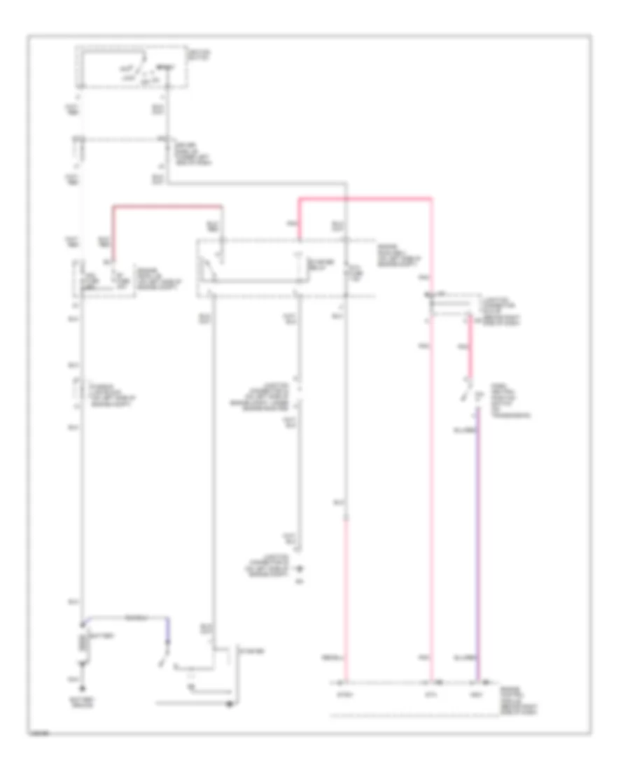
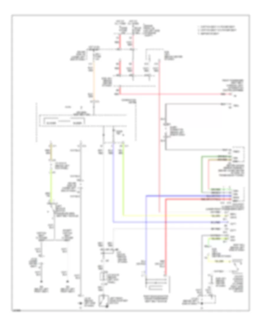
AIR CONDITIONING
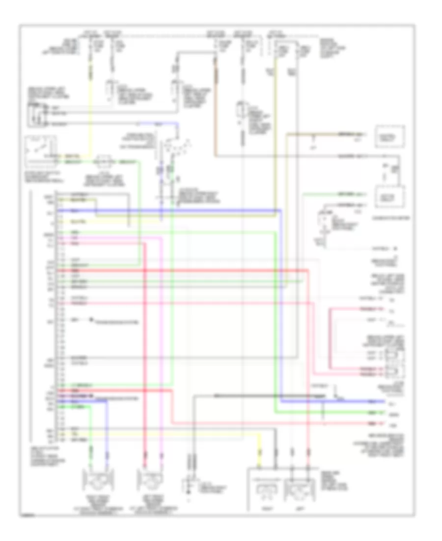
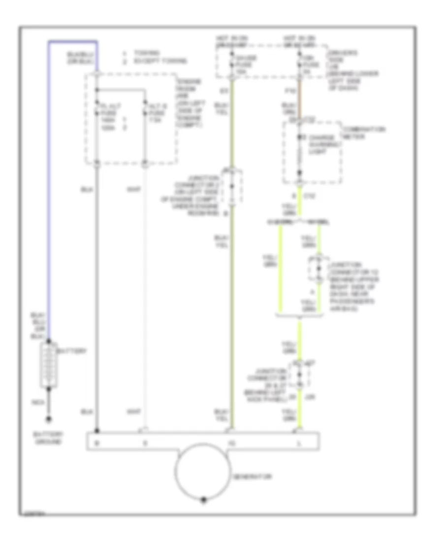
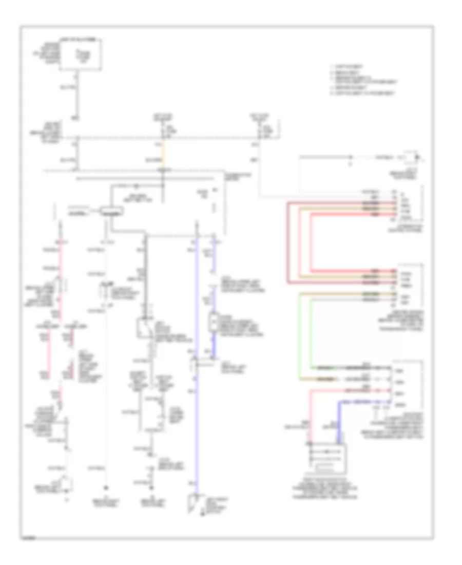
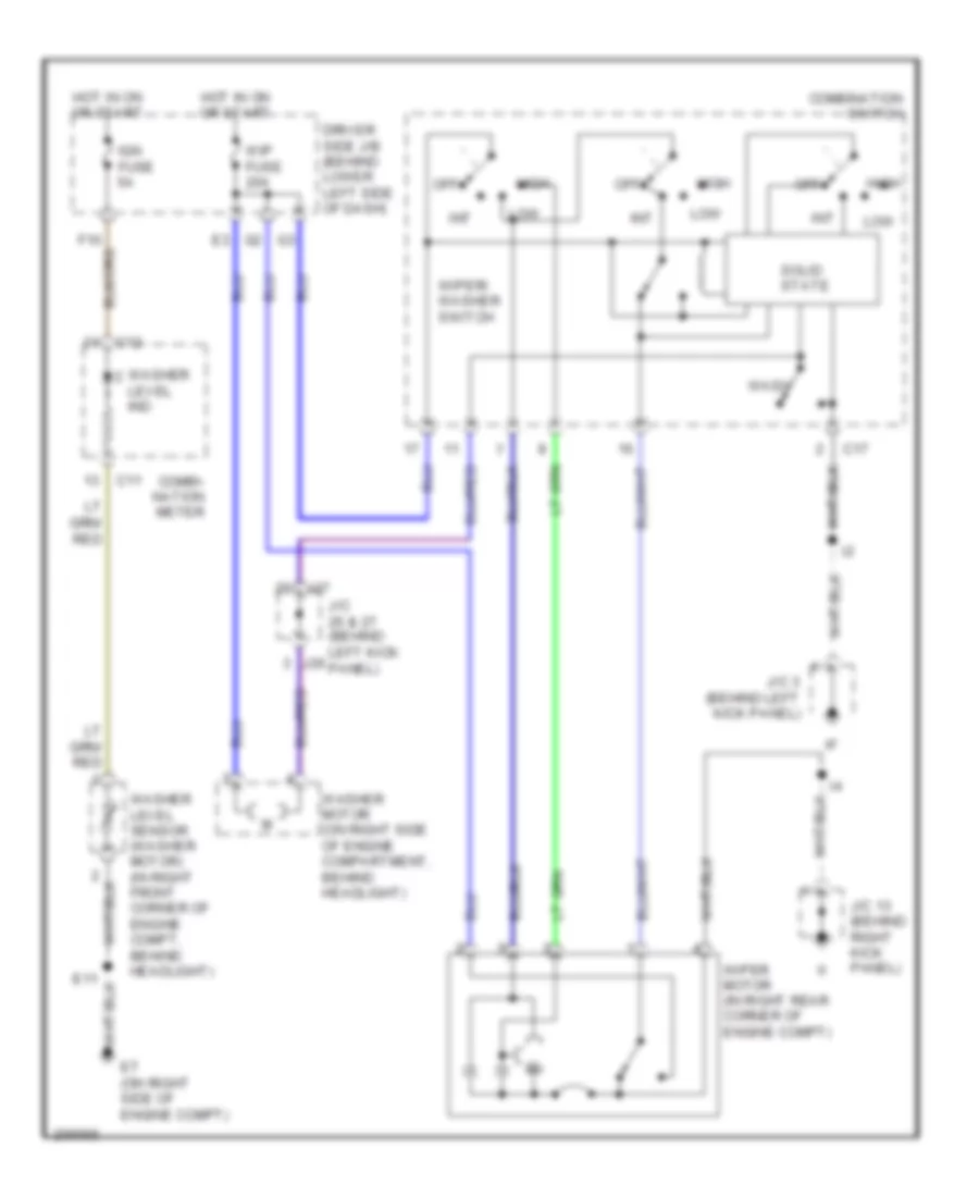
Heater Wiring Diagram, Standard Cab for Toyota Tundra SR5 2006
 https://portal-diagnostov.com/license.html
Automotive Electricians Portal FZCO
Automotive Electricians Portal FZCO
https://portal-diagnostov.com/license.html
https://portal-diagnostov.com/license.html
Automotive Electricians Portal FZCO
Automotive Electricians Portal FZCO
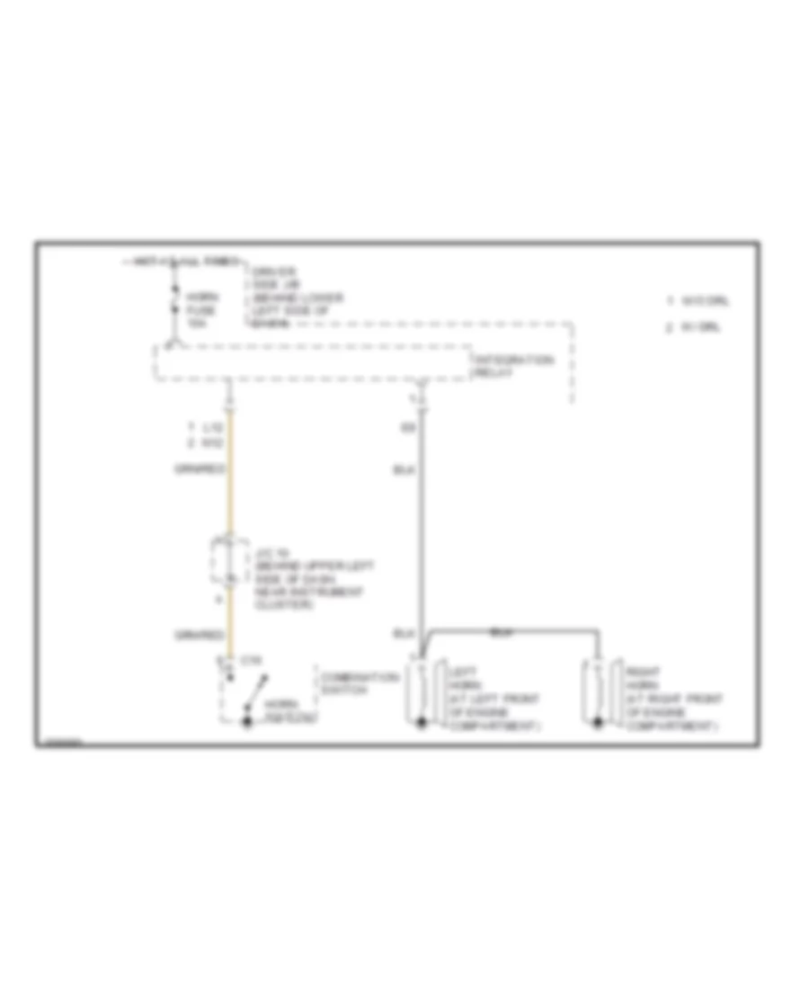
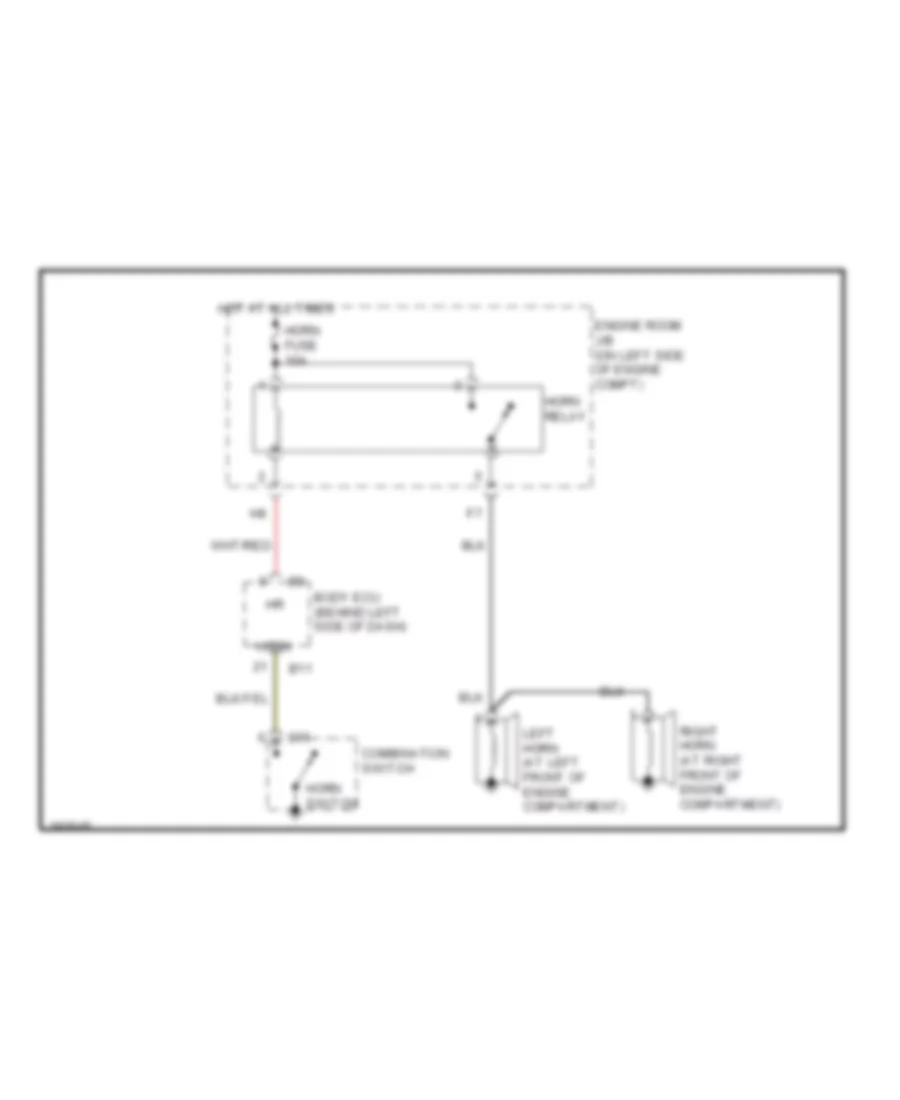
List of elements for Heater Wiring Diagram, Standard Cab for Toyota Tundra SR5 2006:
- (behind right side of dash) blower resistor
- (in dash harness, behind upper right side of dash) i21
- (on left front fender) ea
- (on left side of engine compartment) engine room r/b
- Blower motor (under right side of dash, on hvac housing)
- Blower switch
- Def
- Defroster switch
- Driver's side j/b (behind lower left side of dash)
- Engine room r/b (on left side of engine compartment)
- Gauge fuse 10a
- Heater fuse 50a
- Heater relay
- Hot at all times
- Hot in on or start
- I25
- Integration control & panel
- J26
- J27
- Junction connector (behind right kick panel)
- Junction connector 13 (behind right kick panel)
- Junction connector 18 (on left side of engine compt, under engine room r/b)
- Junction connector 2 (on left side of engine compt)
- Junction connector 26 & 27 (behind left kick panel)
- Junction connector 8 (behind upper left side of dash, near instrument cluster)
- Off
- Red
- Side of dash)
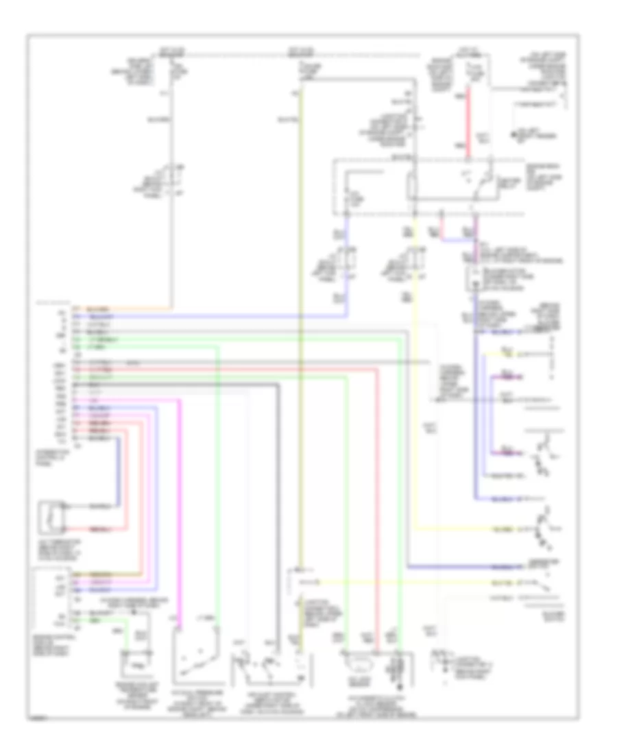
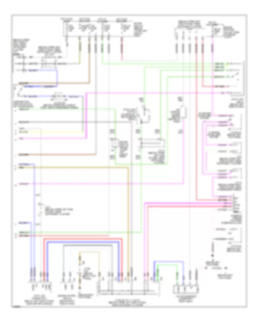
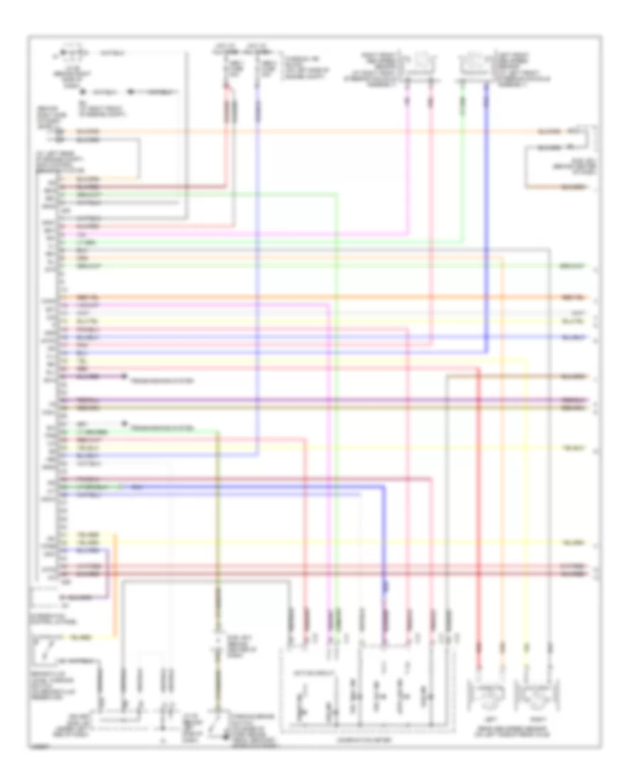
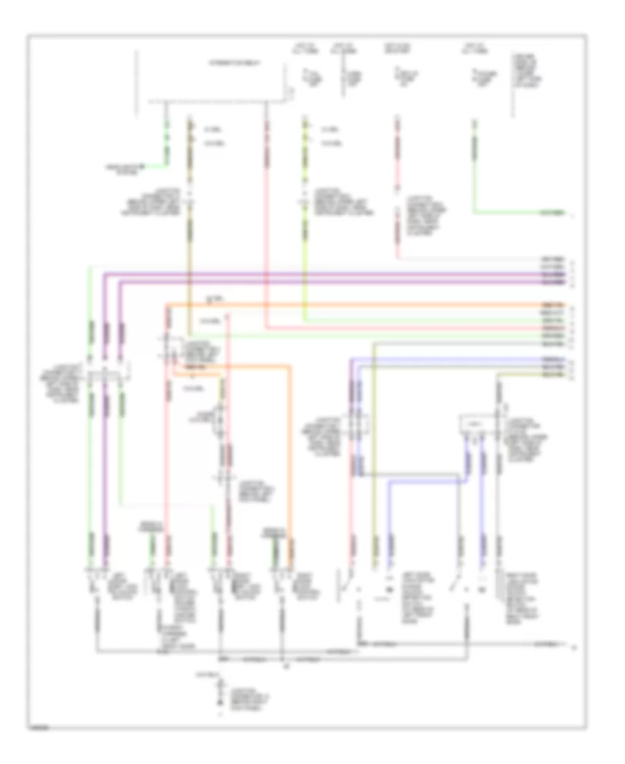
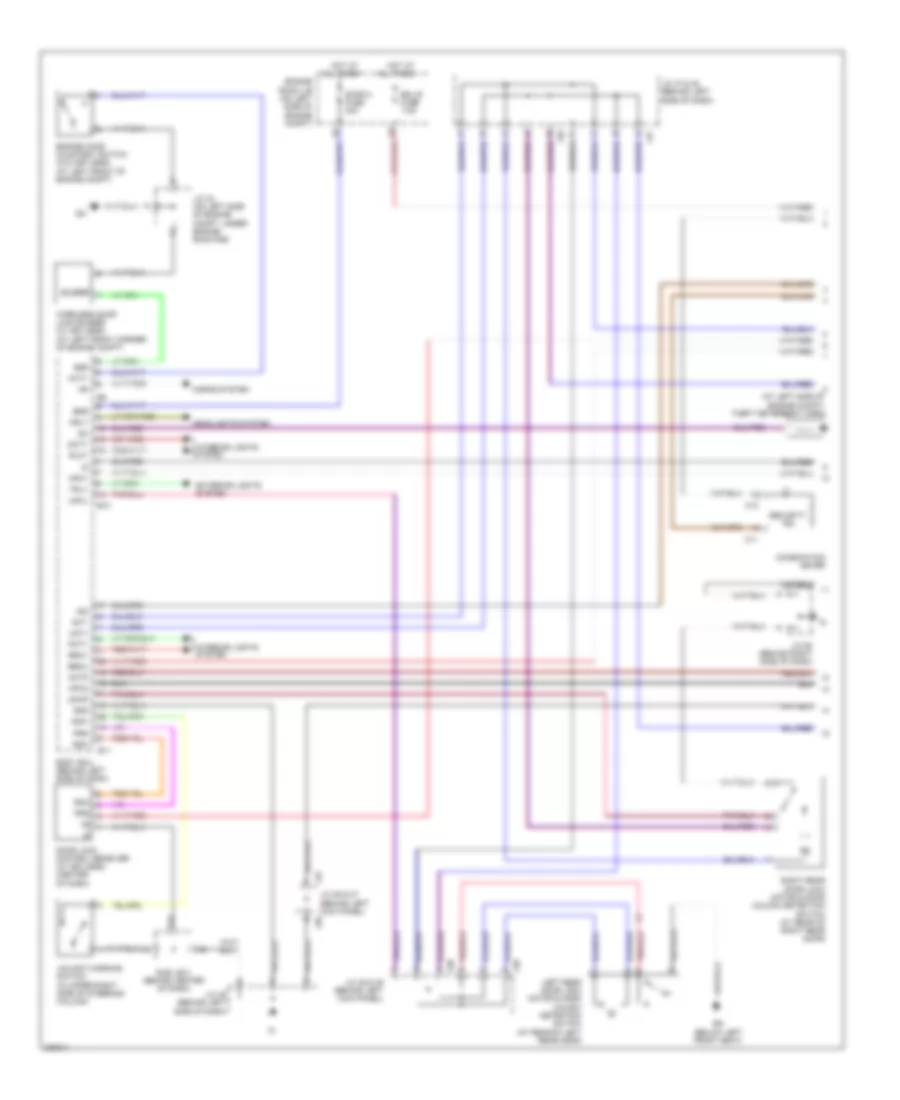
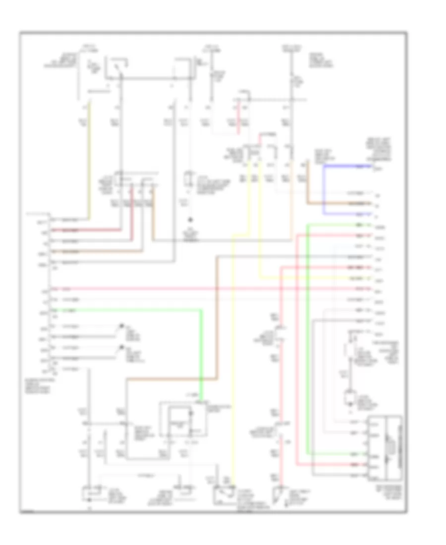
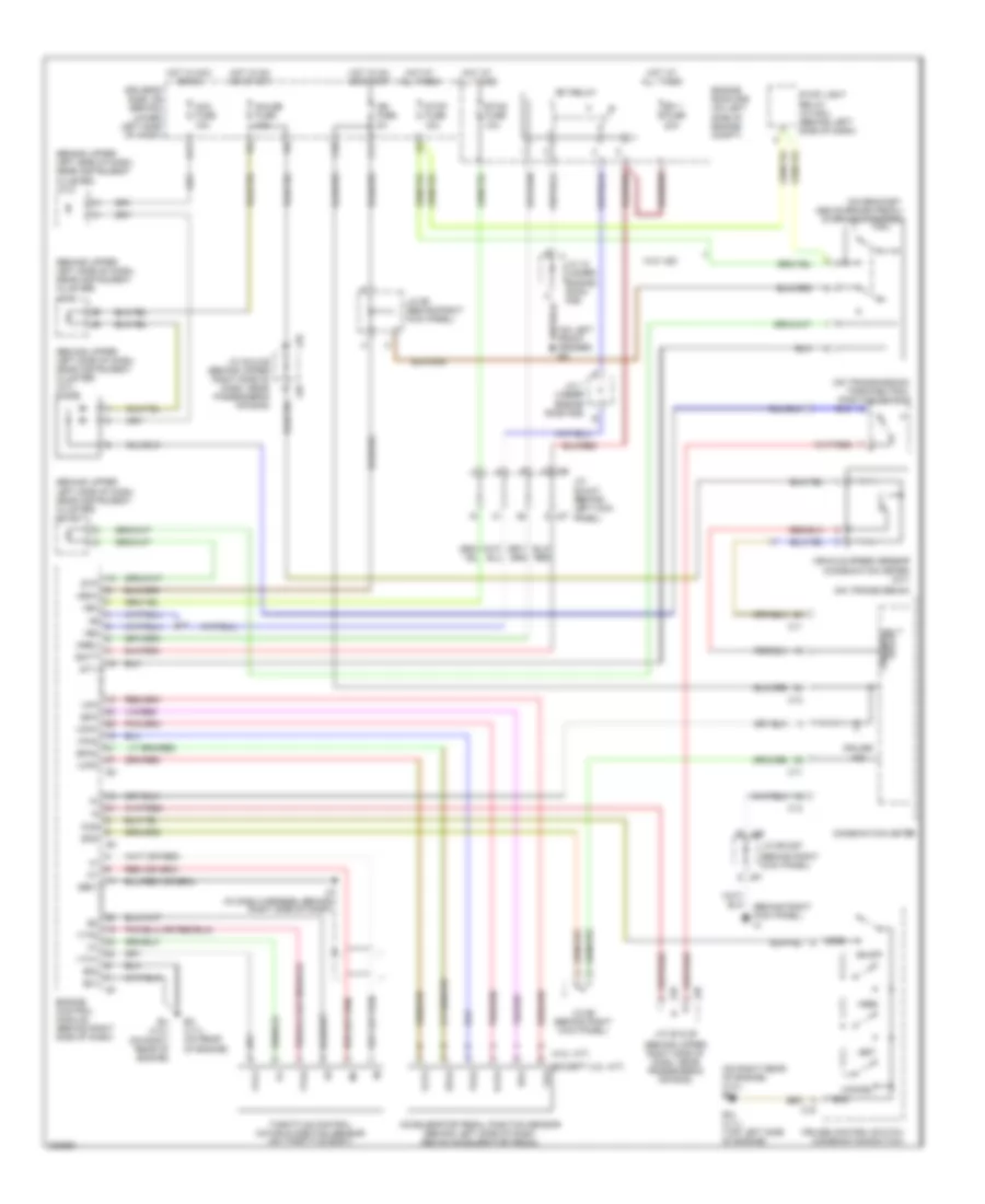
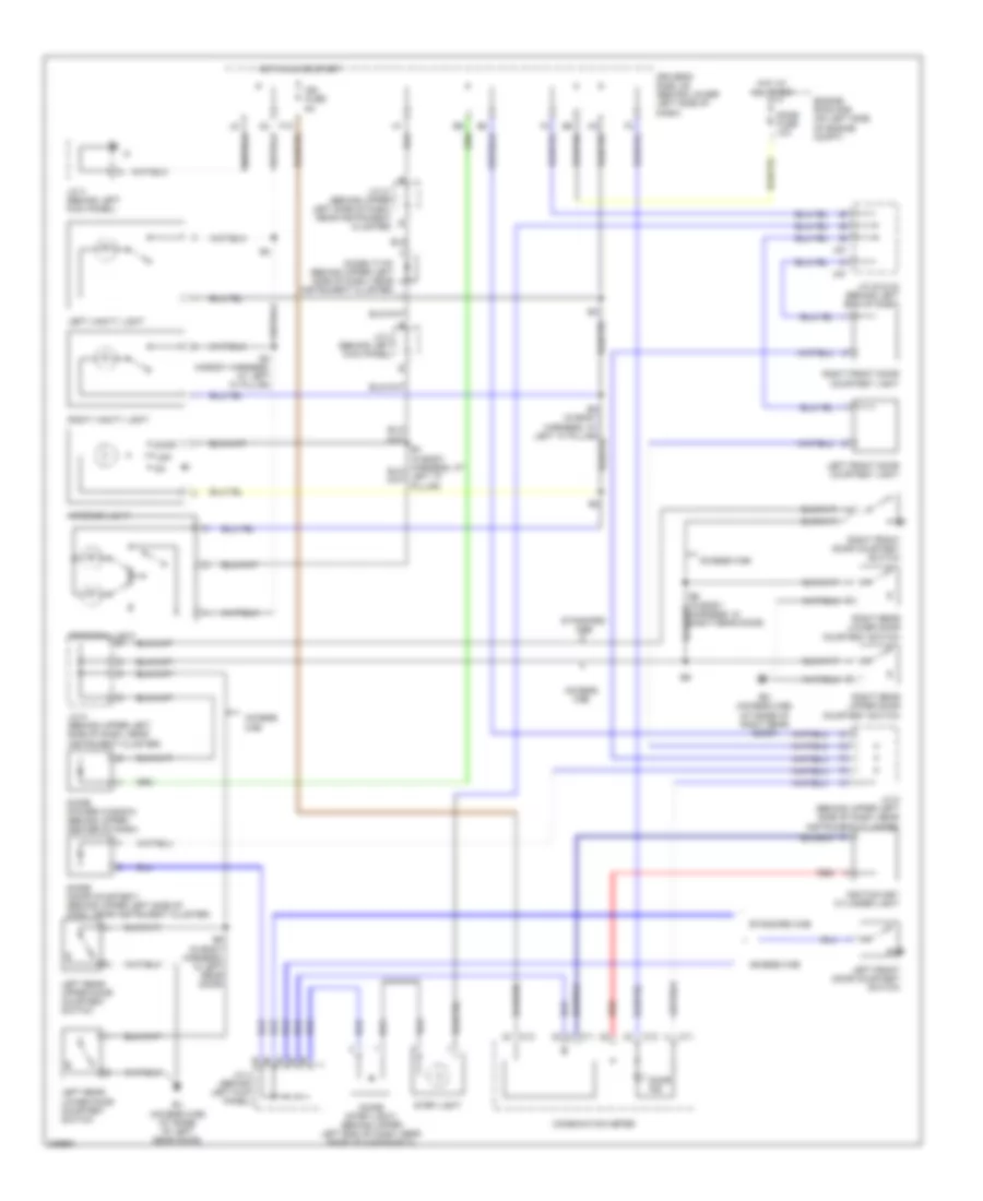
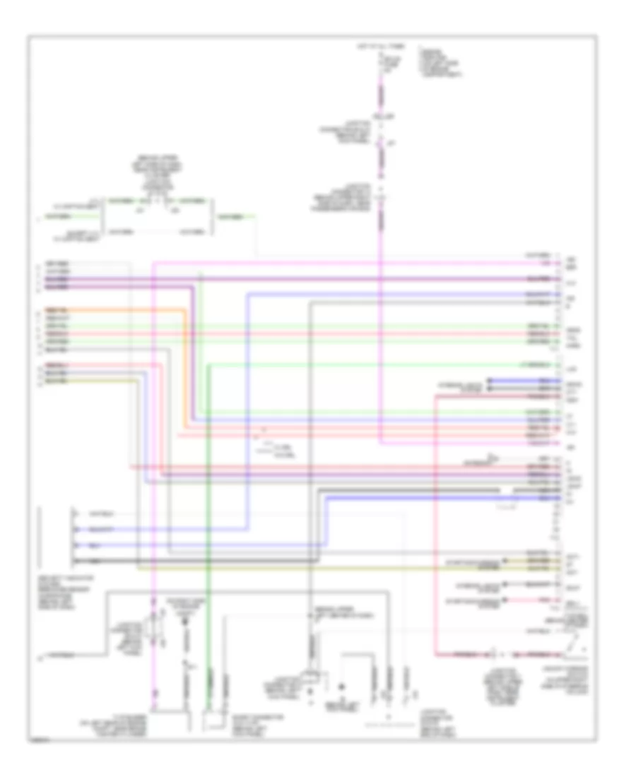
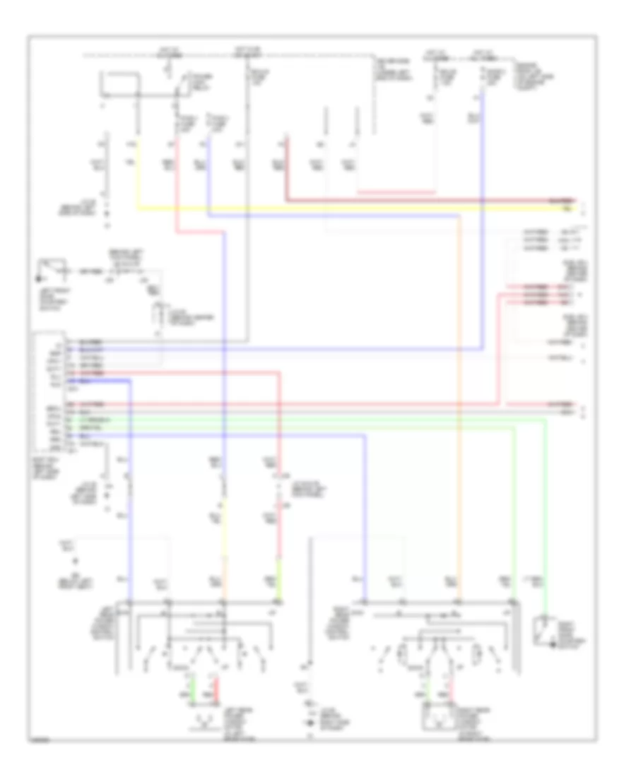
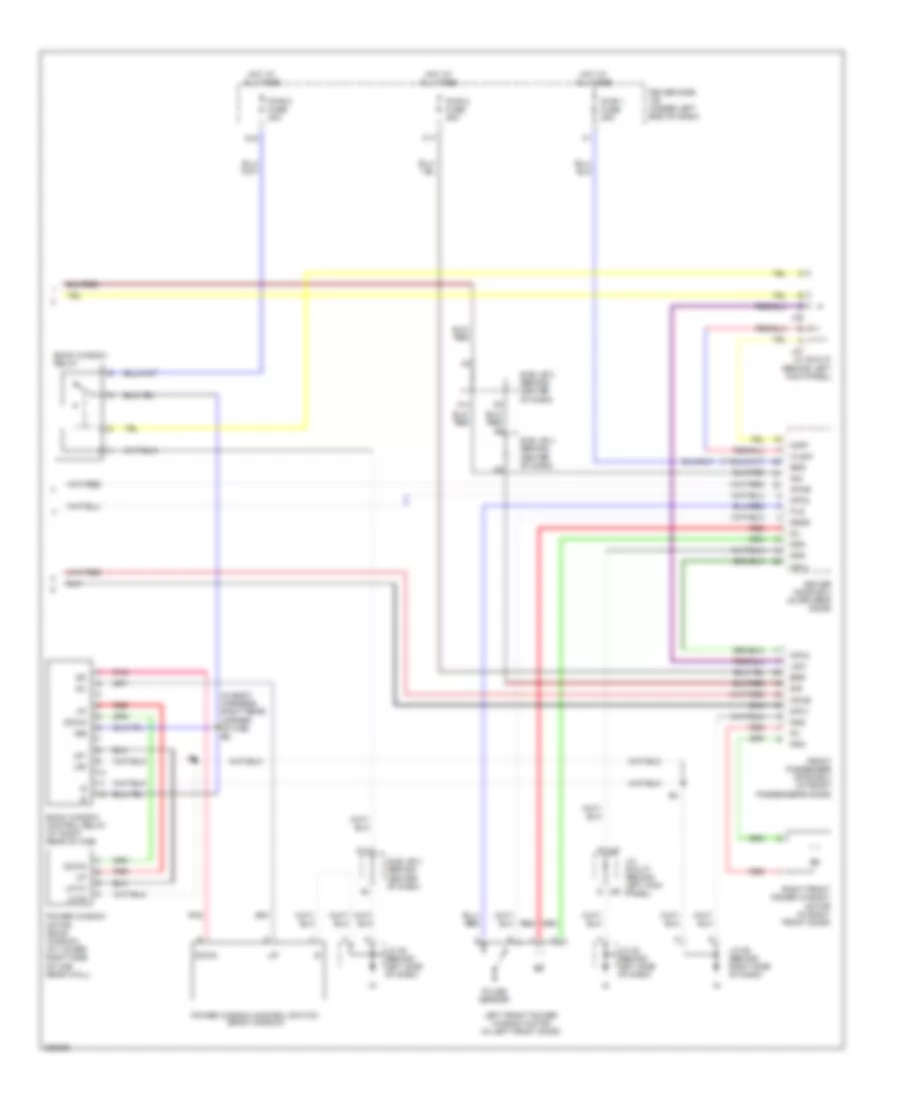
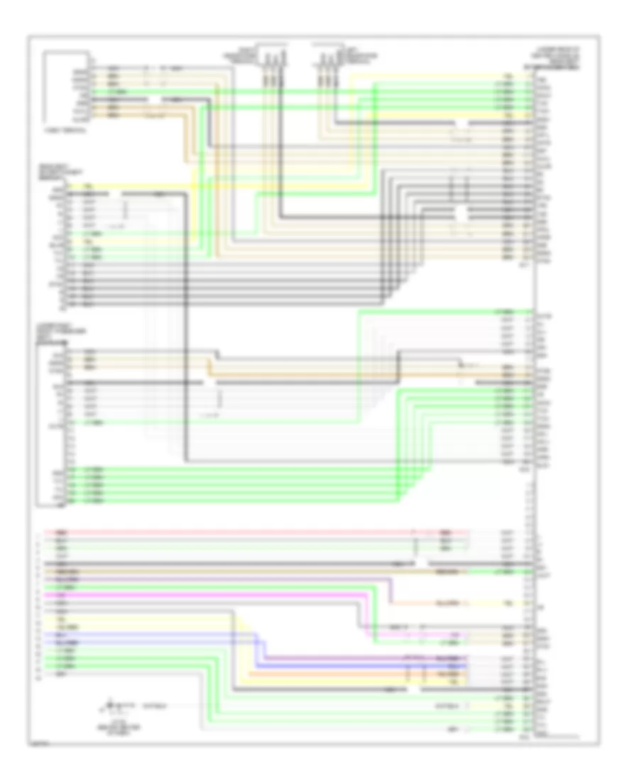
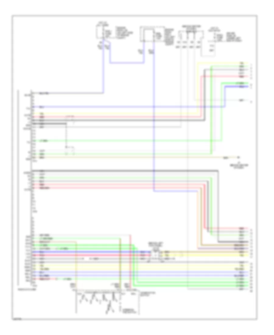
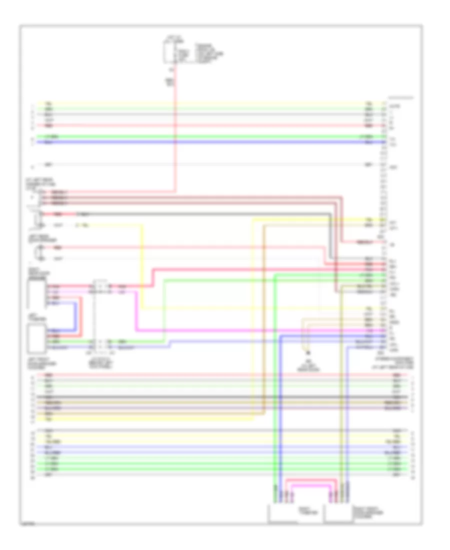
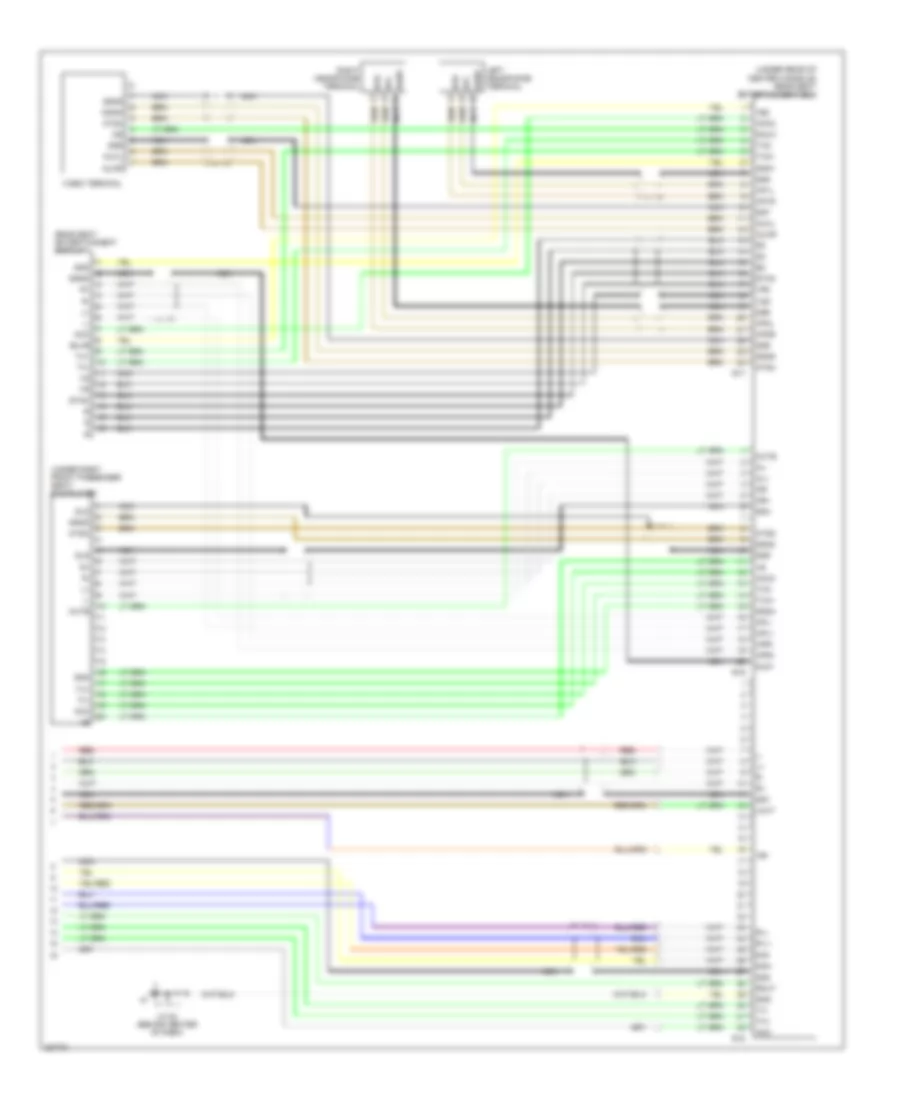
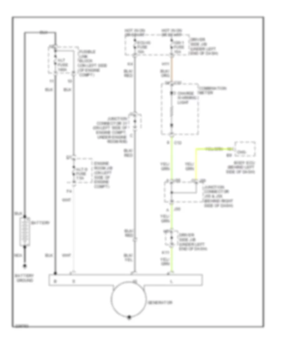
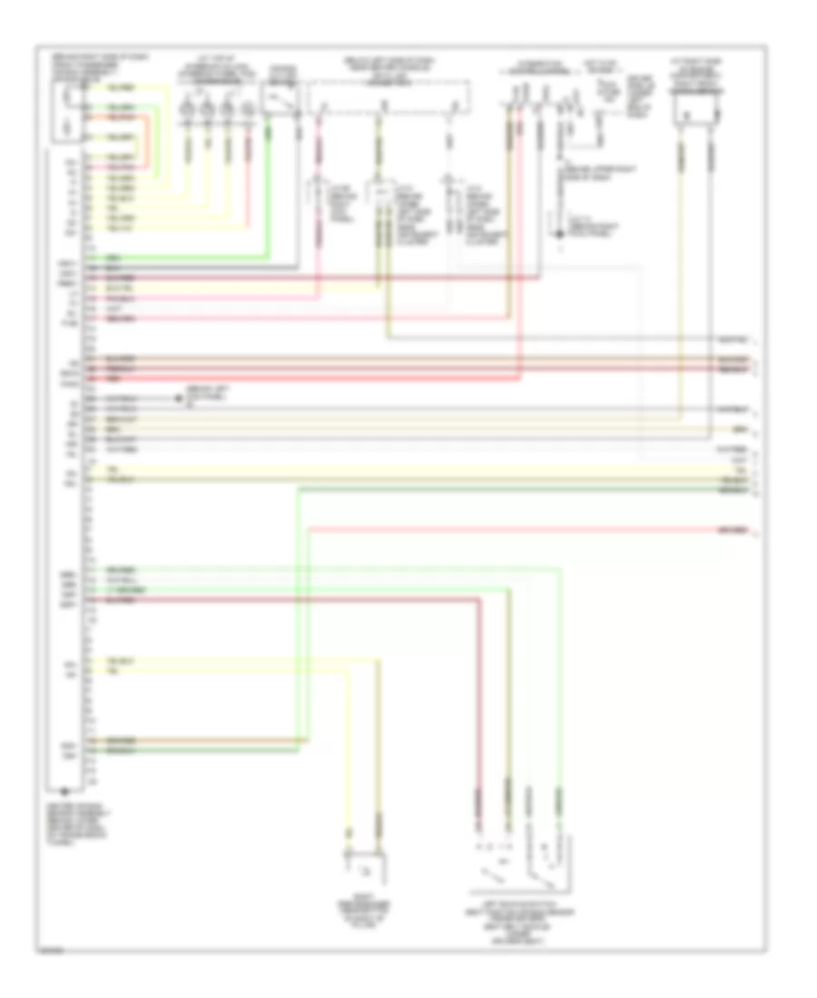
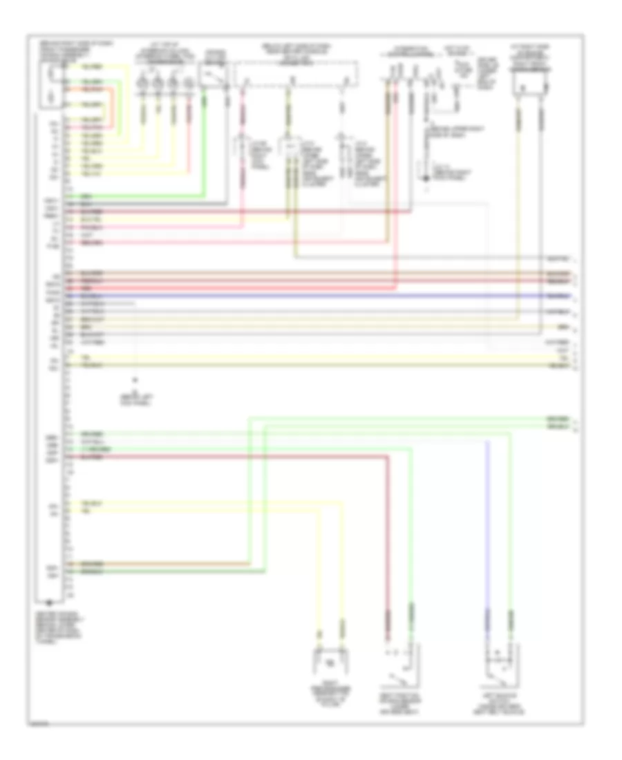
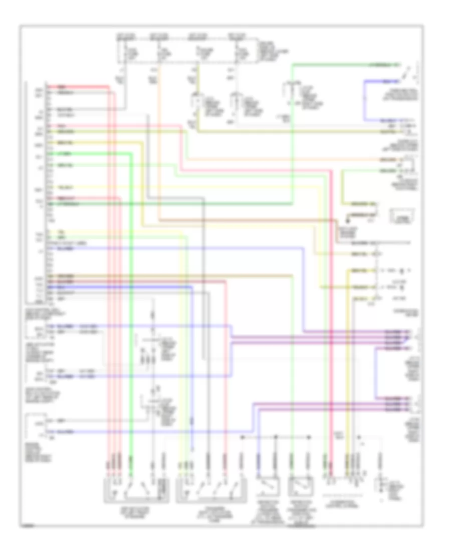
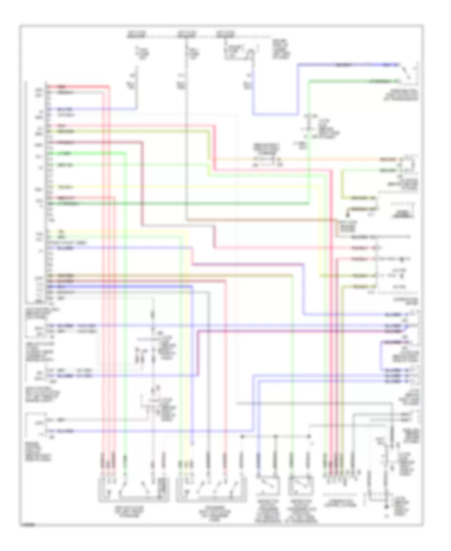
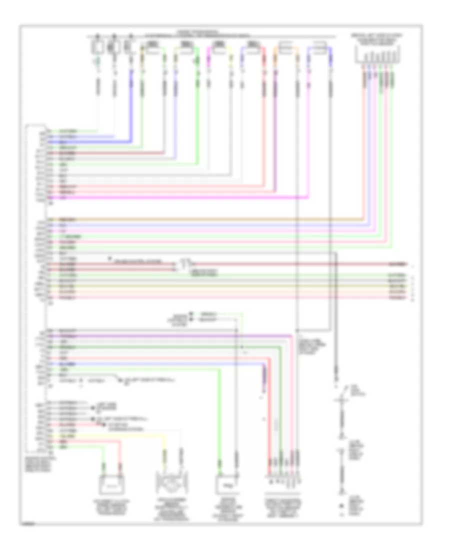
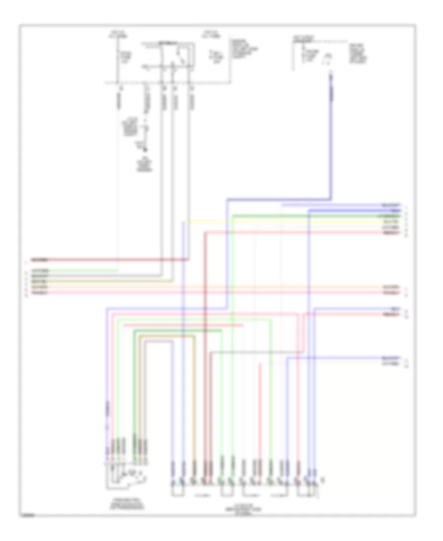
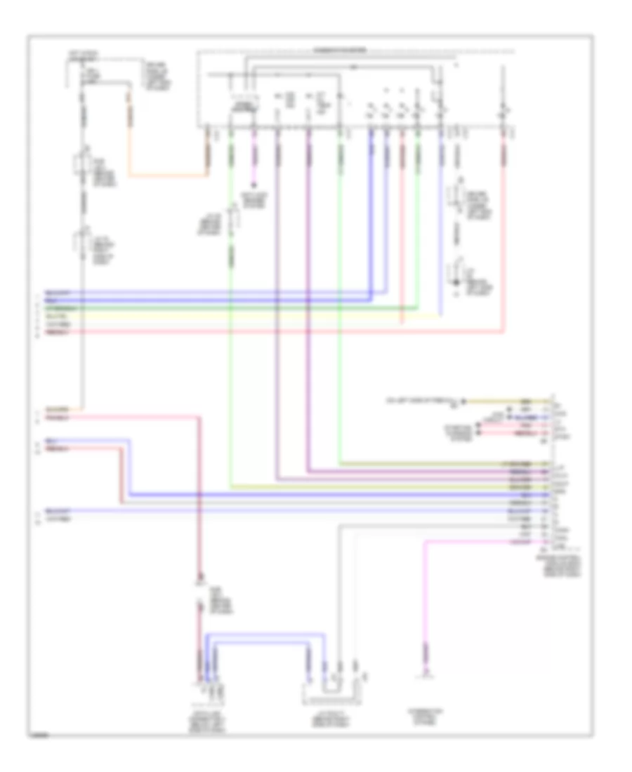
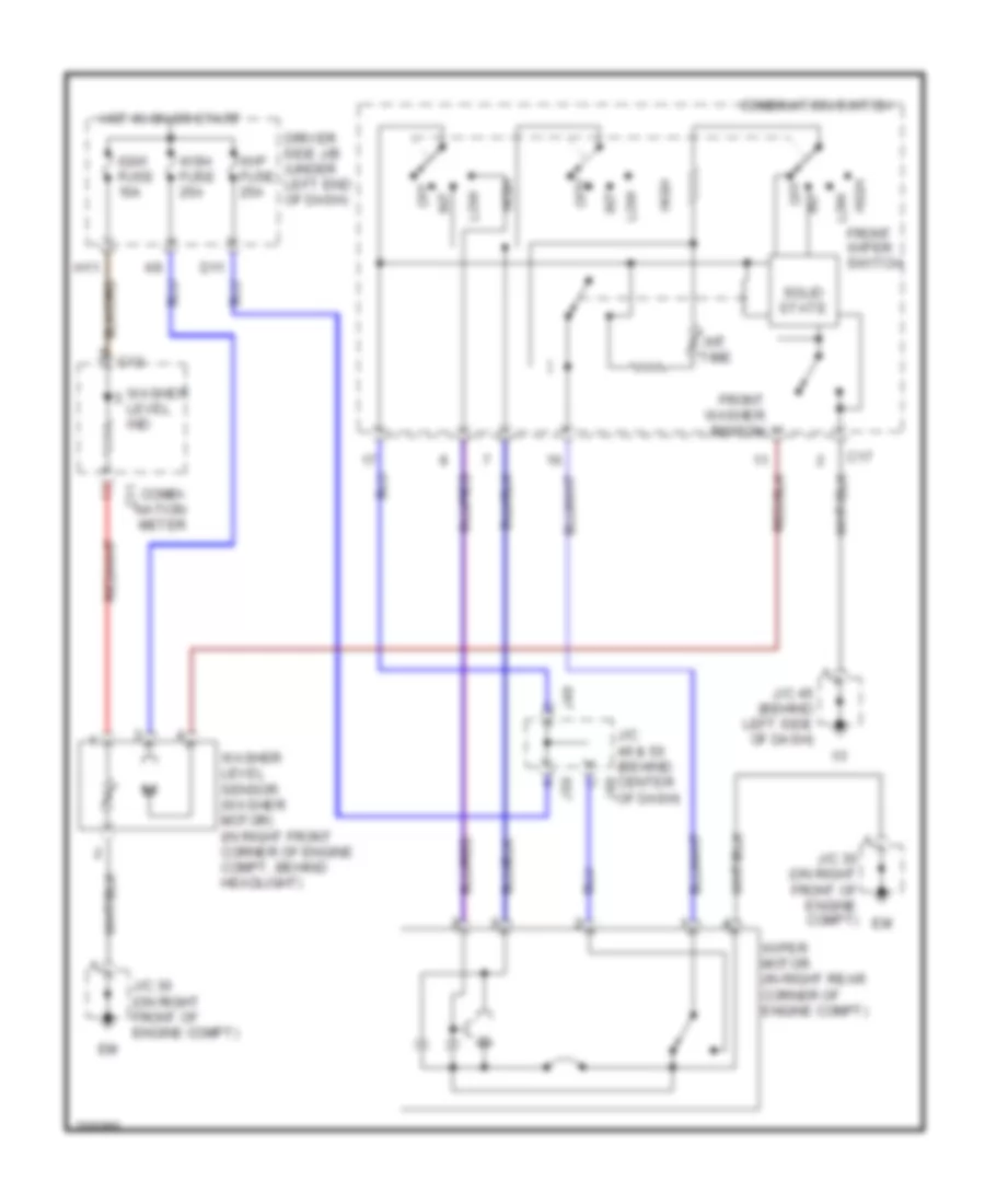
Manual A/C Wiring Diagram, Access/Standard Cab for Toyota Tundra SR5 2006
List of elements for Manual A/C Wiring Diagram, Access/Standard Cab for Toyota Tundra SR5 2006:
- (4.7l)
- (behind right kick panel)
- (behind right side of dash) blower resistor
- (in dash harness, behind right side of dash)
- (in dash harness, behind upper right side of dash) i21
- (in dash harness, behind upper right side of dash) i4
- (on left front fender) ea
- (on left side of engine compt, under engine room r/b) junction connector 18
- A/c
- A/c dual pressure switch (in right front of engine compt, behind headlight)
- A/c fuse 10a
- A/c lock sensor
- A/c magnetic clutch & lock sensor (on a/c compressor, on left front side of engine)
- A/c thermistor (behind right side of dash, in hvac housing)
- Ac1
- Act
- Air inlet control servo motor (under right side of dash, on hvac housing)
- Blower motor (under right side of dash, on hvac housing)
- Blower switch
- Connector 8 (behind upper left side of dash)
- Def
- Defroster switch
- Driver's side j/b (behind lower left side of dash)
- E11 (4.0l: left side of engine compartment) (4.7l: at right front of engine)
- Engine control module (behind right side of dash)
- Engine coolant temperature sensor (on right front of engine)
- Engine room r/b (on left side of engine compt)
- F11
- Frs
- Gauge fuse 10a
- Heater relay
- Hot at all times
- Hot in on or start
- Htr fuse 50a
- I24
- I25
- Ig+
- Ign fuse 5a
- Integration control & panel
- J/c 26 & 27 (behind left kick panel)
- J/c 66 & 67 (behind right kick panel)
- J26
- J27
- J66
- J67
- Junction connector 13
- Junction connector 2 (on left side of engine compt, under engine room r/b)
- Junction e
- Lms
- Lock
- Magnetic clutch
- Off
- Pre
- Rec
- Red
- Sg-1
- Sg-2
- Thw
- Ver1
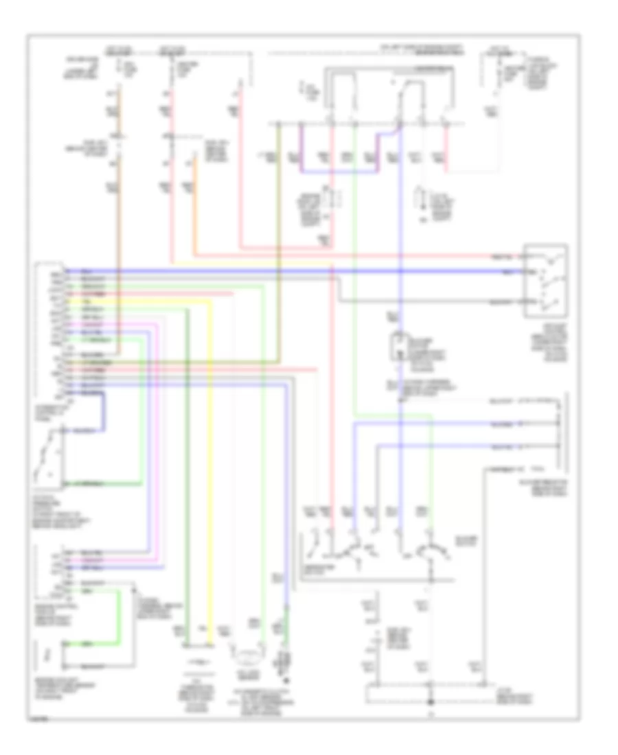
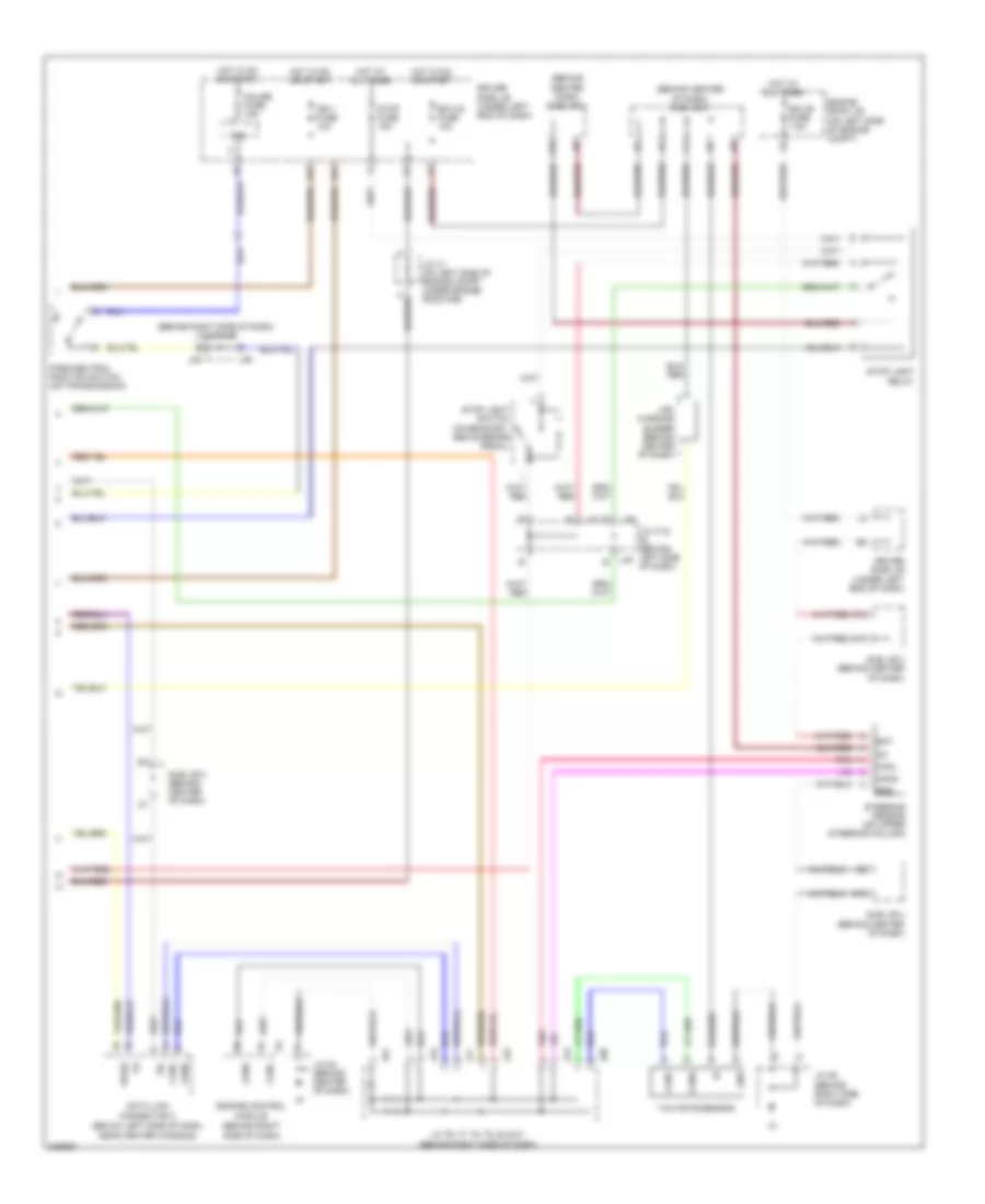
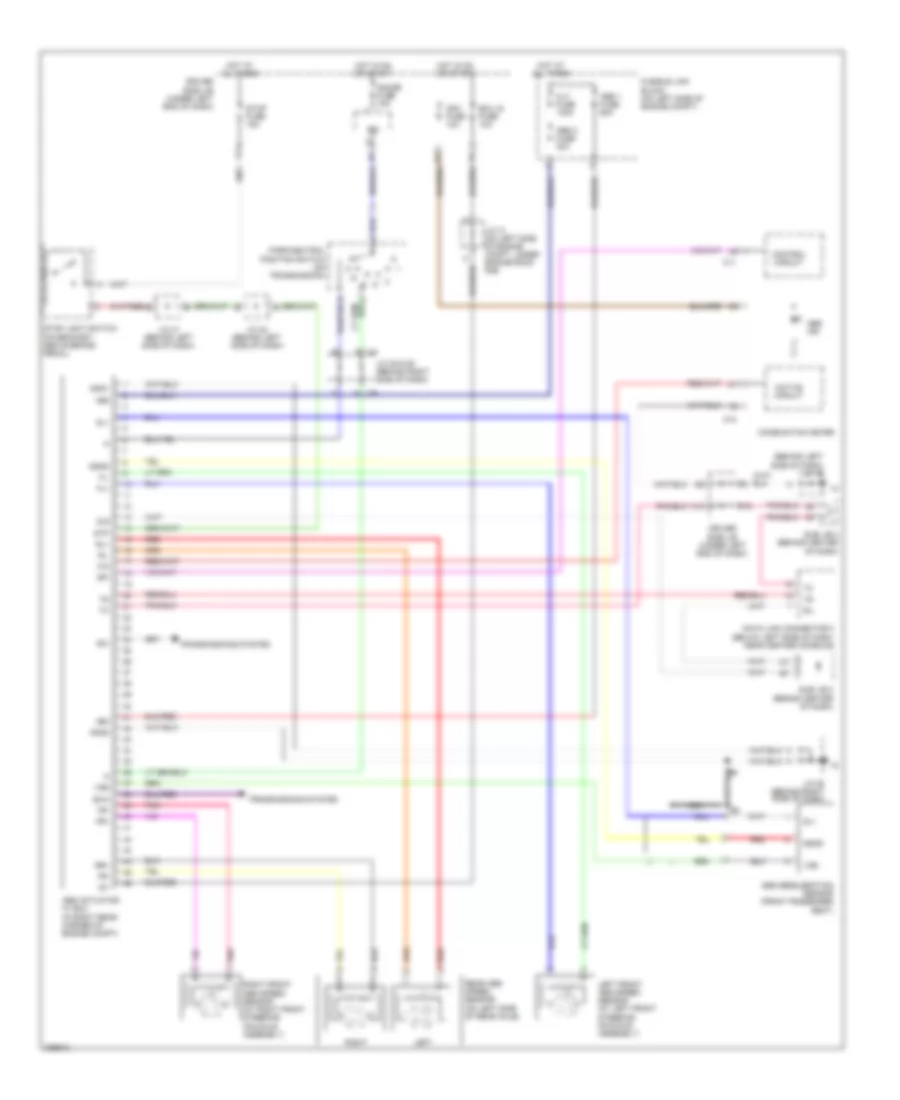
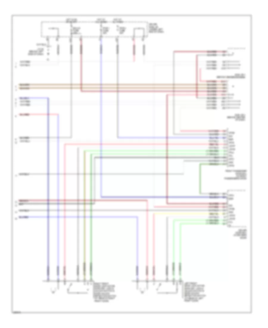
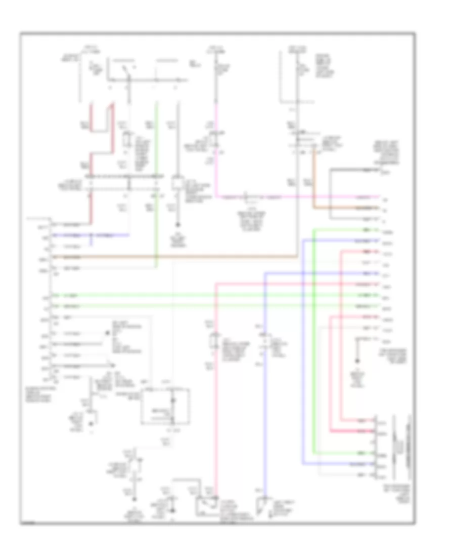
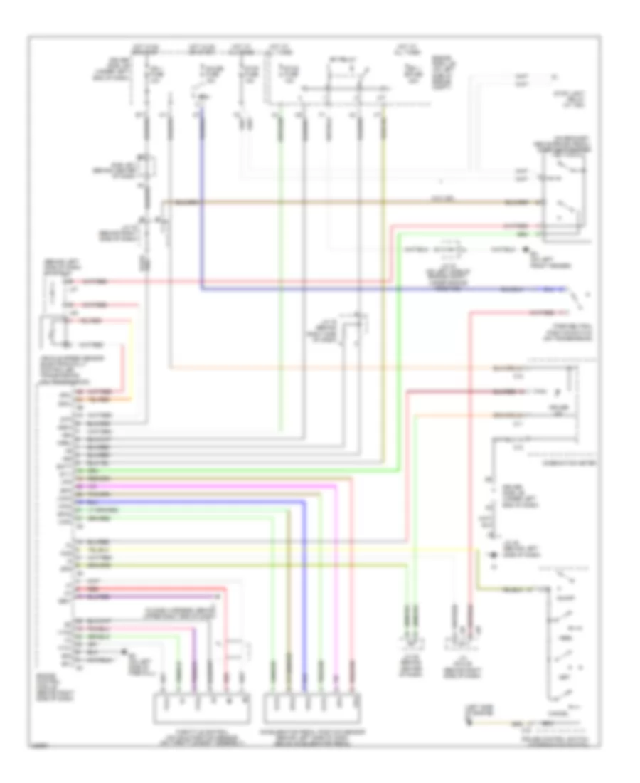
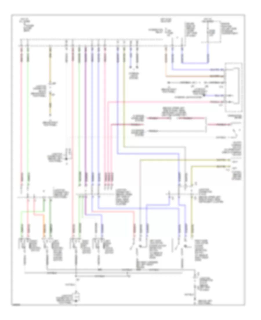
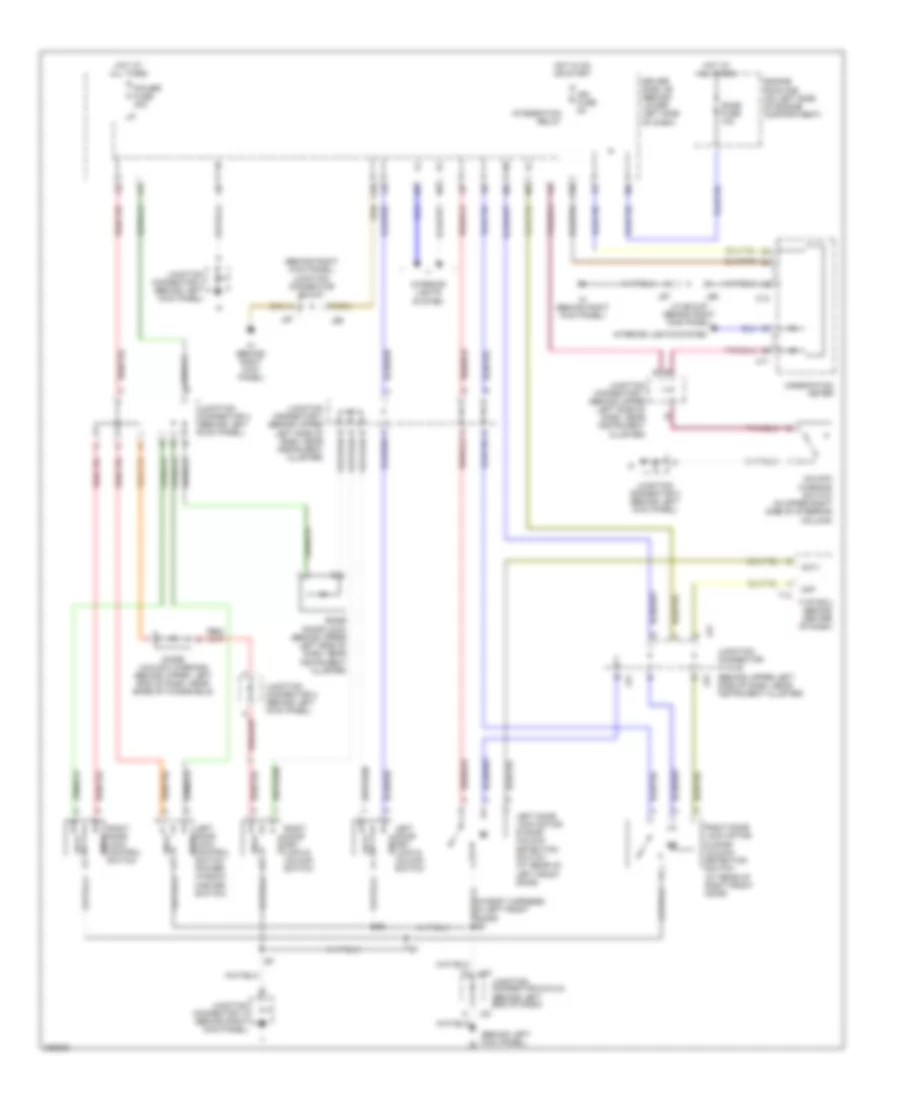
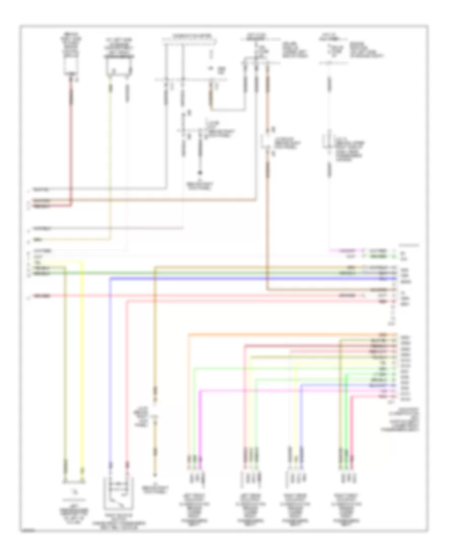
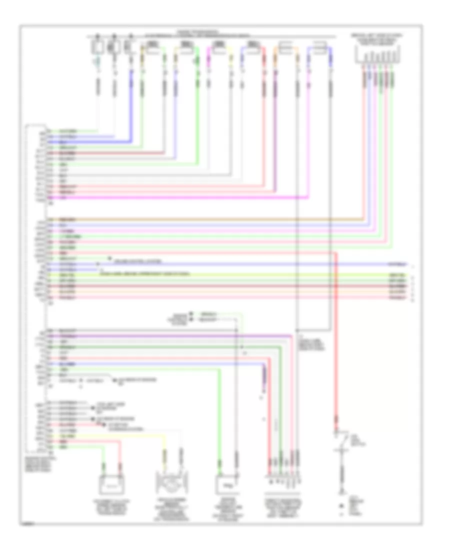
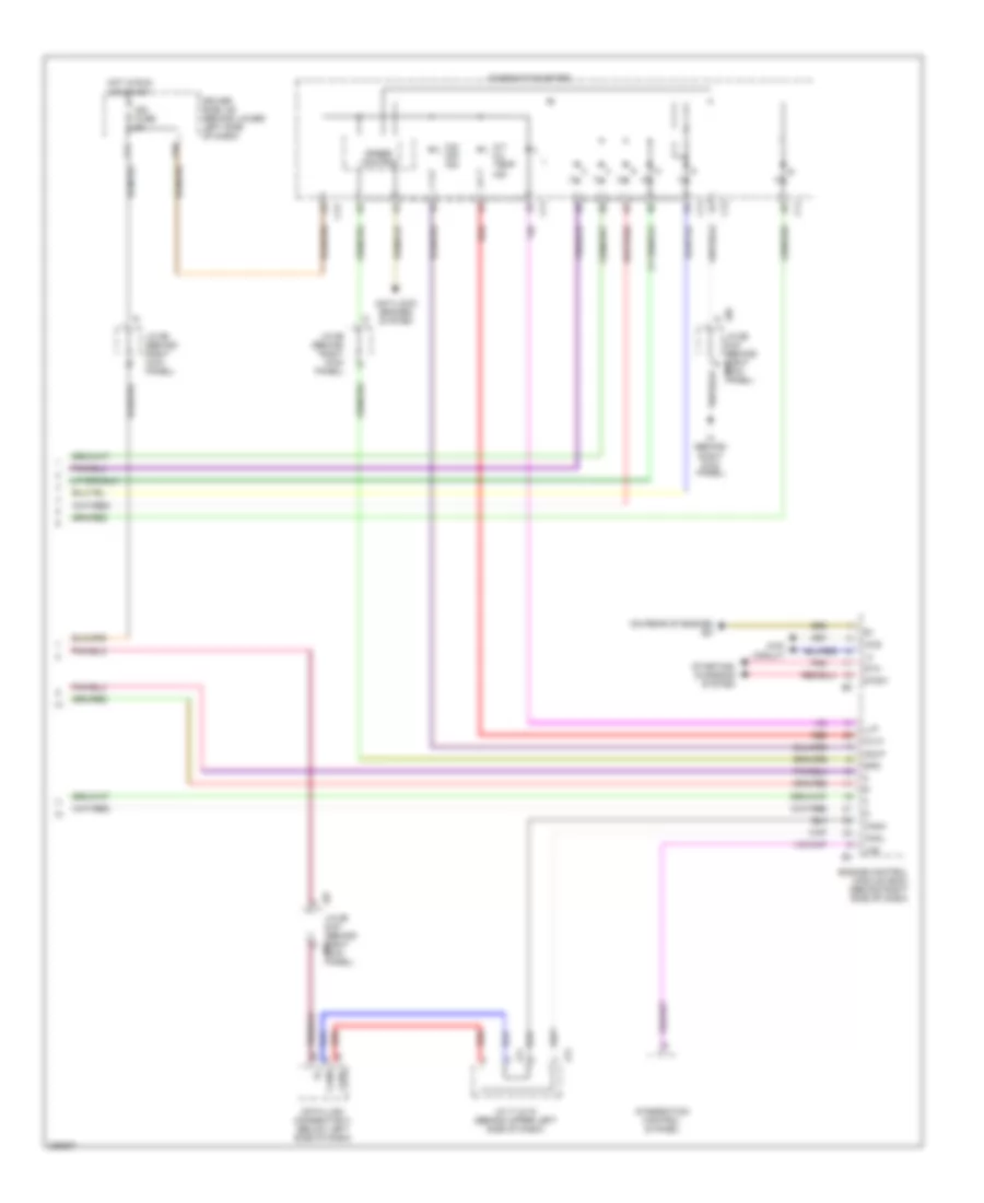
Manual A/C Wiring Diagram, Double Cab for Toyota Tundra SR5 2006
List of elements for Manual A/C Wiring Diagram, Double Cab for Toyota Tundra SR5 2006:
- (on left side of engine compt) engine room r/b 2
- A/c
- A/c dual pressure switch (in right front of engine compartment, behind headlight)
- A/c fuse 7.5a
- A/c lock sensor
- A/c magnetic clutch & lock sensor (4.7l: on a/c compressor, on left front side of engine)
- A/c thermistor (behind right side of dash, in hvac housing)
- Ac1
- Act
- Air inlet control servo motor (under right side of dash, on hvac housing)
- B10
- Behind upper right end of dash) i2
- Blower motor (under right side of dash, on hvac housing)
- Blower resistor (behind right side of dash)
- Blower switch
- D10
- Def
- Defroster switch
- Driver side j/b (under left end of dash)
- E17
- Engine control module (behind right side of dash)
- Engine coolant temperature sensor (on right front of engine)
- Engine room j/b (on left side of engine compt)
- Frs
- Fusible link block (on left side of engine compt)
- Heater fuse 10a
- Heater fuse 50a
- Heater relay
- Hot at all times
- Hot in on or start
- I1 (in dash harness, behind upper right end of dash)
- I24
- I25
- Ig+
- Ign1 fuse 10a
- Integration control & panel
- J/c 35 (on left side of engine compt)
- J/c 58 (behind right side of dash)
- Lms
- Lock
- Magnetic clutch
- Off
- Pre
- Rec
- Sg-1
- Sg-2
- Sub j/b 3 (behind center of dash)
- Sub j/b 4 (behind center of dash)
- Thw
ANTI-LOCK BRAKES
Anti-lock Brakes Wiring Diagram, Access/Standard Cab without VSC for Toyota Tundra SR5 2006
List of elements for Anti-lock Brakes Wiring Diagram, Access/Standard Cab without VSC for Toyota Tundra SR5 2006:
- (behind upper left side of dash, near instrument cluster) (a/t) diode
- (behind upper left side of dash, near instrument cluster) j/c 8
- (below left side of dash, near center console) data link connector 3
- +bm
- +bs
- A/t
- Abs 2 fuse 50a
- Abs 3 fuse 30a
- Abs actuator w/ ecu (in right rear corner of engine compartment)
- Abs deceleration sensor (access cab: under front of center console) (standard cab: under right front seat)
- Abs ind
- Acc fuse 15a
- Active circuit
- C11
- C12
- Combination meter
- Control circuit
- D j66
- D/g
- Driver side j/b (behind lower left side of dash)
- E16
- Ecu ig fuse 5a
- Engine room r/b (on left side of engine compt)
- Exi
- Exi4
- F10
- Fl+
- Fl-
- Fr+
- Fr-
- G11
- G13
- Gauge fuse 10a
- Ggnd
- Gl1
- Gnd1
- Gnd2
- Hot at all times
- Hot in on or acc
- Hot in on or start
- I16
- Ig1
- Ih (behind right kick panel)
- J/c 10 (behind upper left side of dash, near instrument cluster)
- J/c 13 (behind right kick panel)
- J/c 28 & 29 (behind upper right side of dash, near passenger's air bag) j29
- J/c 66 & 67 (behind right kick panel)
- J/c 66 (behind right kick panel)
- J/c 8 (behind upper left side of dash, near instrument cluster)
- J/c 9 (behind upper left side of dash, near instrument cluster)
- J28
- Left
- Left front abs speed sensor (at left front steering knuckle assembly)
- Nca
- Park/neutral position switch (a/t) (on transmission)
- Pnk
- Rear abs speed sensor (on left side of rear axle)
- Red
- Right
- Right front abs speed sensor (at right front steering knuckle assembly)
- Rl+
- Rl-
- Rr+
- Rr-
- Sil
- Spi
- Stop fuse 15a
- Stoplight switch (on bracket, above brake pedal)
- Stp
- Transmissions system
- Vgs
Anti-lock Brakes Wiring Diagram, Access/Standard Cab withVSC (1 of 2) for Toyota Tundra SR5 2006
List of elements for Anti-lock Brakes Wiring Diagram, Access/Standard Cab withVSC (1 of 2) for Toyota Tundra SR5 2006:
- (at left rear of engine compt) skid control ecu w/ actuator
- (behind right kick panel) j/c 66 & 67
- +bm1
- +bm2
- +bs
- A/t
- Abs 2 fuse 50a
- Abs 3 fuse 30a
- Abs ind
- Active circuit
- Auto lsd ind
- Brake fluid level warning switch (on brake fluid reservoir)
- Brake ind
- Brl
- C11
- C12
- Canh
- Canl
- Combination meter
- Csw
- D/g
- E11
- E12
- Ea (on left front fender)
- Engine room r/b (on left side of engine compt)
- Et (4.0l: on right side of engine compt) (4.7l: right front fender)
- Exi
- Exi4
- Fl+
- Fl-
- Fr+
- Fr-
- Gnd1
- Gnd2
- Gnd3
- Hot at all times
- I24
- Ig1
- Ig2
- Ih (behind right kick panel)
- Ind
- Infr
- Integration control & panel
- J/c 18 (on left side of engine compt, under engine room r/b)
- J/c 3 (behind left kick panel)
- J/c 4 (behind left kick panel)
- J/c 66 & 67 (behind j67 right kick panel)
- J66
- J67
- Lbl
- Left
- Left front abs speed sensor (at left front steering knuckle assembly)
- M/t
- Parking brake switch (on base of park brake pedal bracket, near kick panel)
- Pkb
- Pnk
- Rear abs speed sensor (on left side of rear axle)
- Red
- Right
- Right front abs speed sensor (at right front steering knuckle assembly)
- Rl+
- Rl-
- Rr+
- Rr-
- S29
- S30
- Slip ind
- Sp1
- Stp
- Stp2
- Stpo
- Transmissions system
- Vsc off ind
- Vsc trac ind
- Vscw
- Wfse
Anti-lock Brakes Wiring Diagram, Access/Standard Cab withVSC (2 of 2) for Toyota Tundra SR5 2006
List of elements for Anti-lock Brakes Wiring Diagram, Access/Standard Cab withVSC (2 of 2) for Toyota Tundra SR5 2006:
- (behind upper left side of dash, near instrument cluster) (a/t) diode
- (behind upper left side of dash, near instrument cluster) j/c 8 & 9
- (behind upper left side of dash, near instrument cluster) j/c 9
- Acc fuse 15a
- Bat
- Canh
- Canl
- Data link connector 3 (below left side of dash, near center console)
- Driver side j/b (behind lower left side of dash)
- E12
- Ecu-b fuse 5a
- Ecu-ig fuse 5a
- Engine control module (behind right side of dash)
- Engine room r/b (on left side of engine compt)
- Ess
- F10
- F11
- G11
- G13
- Gauge fuse 10a
- Gnd1
- Hot at all times
- Hot in acc or on
- Hot in on or start
- Ie (behind left kick panel)
- Ig1
- Ign fuse 5a
- Ih (behind right kick panel)
- Ii (behind right
- J/c 10 (behind upper left side of dash, near instrument cluster)
- J/c 12 (behind upper right side of dash, near passenger's airbag)
- J/c 23 & 24 (behind left end of dash)
- J/c 26 & 27 (behind left kick panel)
- J/c 28 & 29 (behind upper right side of dash, near passenger's airbag)
- J/c 66 & 67 (behind right kick panel)
- J/c 68, 69, 70, 71, 72 & 73 (behind upper left side of dash, near instrument cluster)
- J/c 8 (behind upper left side of dash, near instrument cluster)
- J/c 9 (behind upper left side of dash, near instrument cluster)
- J23
- J24
- J26
- J27
- J28
- J29
- J66
- J67
- J68
- J69
- J70
- J71
- J72
- J73
- Kick panel)
- Park/neutral position switch (on transmission)
- Pnk
- Red
- Sil
- Steering sensor (on upper steering column)
- Stop fuse 15a
- Stop light relay (behind left side of dash)
- Stop light switch (on bracket, above brake pedal)
- Vsc warning buzzer (behind center of dash)
- W/ engine immobiliser system
- W/o engine immobiliser system
- Wfse
- Yaw rate sensor (under right front seat)
Anti-lock Brakes Wiring Diagram, Double Cab with VSC (1 of 2) for Toyota Tundra SR5 2006
List of elements for Anti-lock Brakes Wiring Diagram, Double Cab with VSC (1 of 2) for Toyota Tundra SR5 2006:
- (at left rear of engine compt) skid control ecu w/ actuator
- (behind right side of dash) j/c 75
- +bm1
- +bm2
- +bs
- A13
- Abs 1 fuse 40a
- Abs 2 fuse 30a
- Abs ind
- Active circuit
- Auto lsd ind
- Brake fluid level warning switch (on brake fluid reservoir)
- Brake ind
- Brl
- C11
- C12
- Canh
- Canl
- Combination meter
- Csw
- D/g
- Driver side j/b (under left end of dash)
- Em (at right front of engine compt)
- Exi
- Exi4
- Fl+
- Fl-
- Fr+
- Fr-
- Fusible link block (on left side of engine compt)
- Gnd1
- Gnd2
- Gnd3
- Hot at all times
- I24
- Ig1
- Ig2
- Ind
- Infr
- Integration control & panel
- J/c 45 (behind left side of dash)
- J/c 58 (behind right side of dash)
- K12
- Lbl
- Left
- Left front abs speed sensor (at left front steering knuckle assembly)
- Parking brake switch (on base of park brake pedal bracket, near kick panel)
- Pkb
- Pnk
- Rear abs speed sensor (on left side of rear axle)
- Red
- Right
- Right front abs speed sensor (at right front steering knuckle assembly)
- Rl+
- Rl-
- Rr+
- Rr-
- S29
- S30
- Slip ind
- Sp1
- Stp
- Stp2
- Stpo
- Sub j/b 3 (behind center of dash)
- Transmissions system
- Vsc off ind
- Vsc trac ind
- Vscw
- Wfse
Anti-lock Brakes Wiring Diagram, Double Cab with VSC (2 of 2) for Toyota Tundra SR5 2006
List of elements for Anti-lock Brakes Wiring Diagram, Double Cab with VSC (2 of 2) for Toyota Tundra SR5 2006:
- (behind center dash) sub j/b 4
- (behind center of dash) sub j/b 3
- (behind right side of dash) j/c 28 & 29
- A18
- Bat
- Canh
- Canl
- D10
- Data link connector 3 (below left side of dash, near center console)
- Driver side j/b (under left end of dash)
- E10
- E17
- Ecu-b fuse 7.5a
- Ecu-ig fuse 10a
- Engine control module (behind right side of dash)
- Engine room j/b (on left side of engine compt)
- Ess
- Gauge fuse 15a
- Gnd
- H11
- Hot at all times
- Hot in on or start
- Ig1
- Ign 1 fuse 10a
- Ipo
- J/c 31 (on left side of engine compt, under engine room r/b)
- J/c 47 & (behind left side of dash)
- J/c 54 (behind center of dash)
- J/c 58 (behind right side of dash)
- J/c 76, 77, 78, 79, 80 & 81 (behind right side of dash)
- J28
- J29
- J47
- J48
- J76
- J77
- J78
- J79
- J80
- J81
- Park/neutral position switch (on transmission)
- Pnk
- Sil
- Steering sensor (on upper steering column)
- Stop fuse 15a
- Stop light relay
- Stop light switch (on bracket, above brake pedal)
- Sub j/b 3 (behind center of dash)
- Sub j/b 4 (behind center of dash)
- Vsc warning buzzer (behind center of dash)
- Wfse
- Yaw rate sensor
Anti-lock Brakes Wiring Diagram, Double Cab without VSC for Toyota Tundra SR5 2006
List of elements for Anti-lock Brakes Wiring Diagram, Double Cab without VSC for Toyota Tundra SR5 2006:
- (behind left side of dash) j/c 45
- +bm
- +bs
- Abs 1 fuse 60a
- Abs 2 fuse 30a
- Abs actuator w/ ecu (in right rear corner of engine compt)
- Abs deceleration sensor (front passenger seat)
- Abs ind
- Active circuit
- Alt fuse 140a
- C11
- C12
- Combination meter
- Control circuit
- D/g
- Data link connector 3 (below left side of dash, near center console)
- Driver side j/b (under left end of dash)
- Ecu ig fuse 10a
- Exi
- Exi4
- F15
- Fl+
- Fl-
- Fr+
- Fr-
- Fusible link block (on left side of engine compt)
- G j29
- Gauge fuse 15a
- Ggnd
- Gl1
- Gnd1
- Gnd2
- H11
- Hot at all times
- Hot in on or start
- Ig1
- Ign1 fuse 10a
- Ipo
- J/c 28 & 29 (behind right side of dash)
- J/c 31 (on left side of engine compt, under engine room r/b)
- J/c 47 (behind left side of dash)
- J/c 48 (behind left side of dash)
- J/c 58 (behind right side of dash)
- J28
- K10
- Left
- Left front abs speed sensor (at left front steering knuckle assembly)
- Nca
- Park/neutral position switch (on transmission)
- Pnk
- Rear abs speed sensor (on left side of rear axle)
- Red
- Right
- Right front abs speed sensor (at right front steering knuckle assembly)
- Rl+
- Rl-
- Rr+
- Sil
- Spi
- Stop fuse 15a
- Stop light switch (on bracket, above brake pedal)
- Stp
- Sub j/b 3 (behind center of dash)
- Transmissions system
- Vgs
ANTI-THEFT
Forced Entry Wiring Diagram, Access/Standard Cab with Keyless Entry (1 of 2) for Toyota Tundra SR5 2006
List of elements for Forced Entry Wiring Diagram, Access/Standard Cab with Keyless Entry (1 of 2) for Toyota Tundra SR5 2006:
- (ends in harness)
- (in body harness, in left front door) b3
- Diode (w/o drl)
- Driver side j/b (behind lower left side of dash)
- Ecu ig fuse 5a
- G13
- Headlights system
- Horn fuse 10a
- Hot at all times
- Hot in on or start
- Integration relay
- J21
- Junction connector 10 (behind upper left side of dash, near instrument cluster)
- Junction connector 13 (behind right kick panel)
- Junction connector 21 & 22 (behind upper j22 left side of dash, near instrument cluster)
- Junction connector 4 (behind left kick panel)
- Junction connector 5 (behind upper left side of dash, near instrument cluster)
- Junction connector 7 (behind upper left side of dash, near instrument cluster)
- Junction connector 9 (behind upper left side of dash, near instrument cluster)
- L12
- L15
- Left door key lock & unlock lock switch
- Left door lock control unlk switch (power window master switch)
- Left door lock motor & door unlock detection switch (at rear of left front door)
- Lock
- N12
- N14
- Power fuse 30a
- Right door key lock & unlock unlk switch
- Right door lock control unlk switch
- Right door lock motor & door unlock detection switch (at rear of right front door)
- Tail fuse 15a
- Unlk
- W/ drl
- W/o drl
Forced Entry Wiring Diagram, Access/Standard Cab with Keyless Entry (2 of 2) for Toyota Tundra SR5 2006
List of elements for Forced Entry Wiring Diagram, Access/Standard Cab with Keyless Entry (2 of 2) for Toyota Tundra SR5 2006:
- (behind left end of dash)
- (behind upper left center of dash) i2
- (behind upper left side of dash, near instrument cluster) junction connector 21 & 22
- (on right side of engine
- +b1
- +b2
- 4.7l w/ captain seat
- Act+
- Act-
- Antenna
- Bzr
- Compt) et
- Cty
- Dmlp
- Dswd
- E11
- Ecu-b fuse 5a
- Engine room r/b (on left side of engine compartment)
- Except 4.7l w/ captain seat
- Head
- Horn
- Hot at all times
- Ie (behind left kick panel)
- Ind
- Interior lights system
- J21
- J22
- J23
- J24
- J26
- J27
- Junction connector 12 (behind upper right side of dash, near passenger's air bag)
- Junction connector 23 & 24
- Junction connector 26 & 27 (behind left kick panel)
- Junction connector 3 (behind left kick panel)
- Junction connector 7 (behind upper left side of dash, near instrument cluster)
- Ksw
- Lswd
- Lswp
- Lug
- Mi+
- Mi-
- Nca
- Pnk
- Security indicator & glass breakage sensor microphone (behind left side of dash)
- Short connector (w/o tvip) (behind left kick panel)
- Srly
- Starting/charging system
- T11
- T12
- T13
- Tail
- Tvip buzzer (on left rear of engine compt, near brake master cylinder)
- Tvip ecu (behind center of dash)
- Ul1
- Ul2
- Ul3
- Unlock warning switch (in upper right side of steering column)
- W/ drl
- W/o drl
Forced Entry Wiring Diagram, Double Cab (1 of 2) for Toyota Tundra SR5 2006
List of elements for Forced Entry Wiring Diagram, Double Cab (1 of 2) for Toyota Tundra SR5 2006:
- (at left side of engine compt) theft deterrent horn
- A12
- Act+
- Act-
- Actd
- All times
- B10
- B11
- Bdr
- Becu
- Body ecu (behind left side of dash)
- Bq (below left front seat)
- Buzzer
- Bzr
- C11
- C12
- Combination meter
- Dcty
- Door 2 fuse 30a
- Door lock control receiver (w/ keyless) (center of dash)
- Ecu b fuse 7.5a
- Engine hood courtesy switch (w/o keyless) (at left front of engine compt)
- Engine room j/b (on left side of engine compt)
- Exterior lights system
- Gnd
- Hcty
- Headlights system
- Horns system
- Hot at
- Hrly
- Ind
- Interior lights
- Interior lights system
- J/c 34 (on left side of engine compt, under engine room r/b)
- J/c 36 & 37 (behind left kick panel)
- J/c 38 & 39 (behind left kick panel)
- J/c 45 (behind left side of dash)
- J/c 47 & 48 (behind left side of dash)
- J/c 58 (behind right side of dash)
- J36
- J37
- J38
- J39
- J47
- J48
- Ksw
- Left rear door lock motor & door unlock detection switch (at rear of left rear door)
- Lswl
- Lswr
- Mpx1
- Mpx2
- Pcty
- Prg
- Rda
- Right rear door lock motor & door unlock detection switch (at rear of right rear door)
- Rlcy
- Rrcy
- Security ind
- Sub j/b 3 (behind center of dash)
- System
- Trly
- Unlock warning switch (in upper right side of steering column)
- Wireless door lock buzzer (w/ keyless) (at left front corner of engine compt)
Forced Entry Wiring Diagram, Double Cab (2 of 2) for Toyota Tundra SR5 2006
List of elements for Forced Entry Wiring Diagram, Double Cab (2 of 2) for Toyota Tundra SR5 2006:
- A10
- A14
- A19
- A20
- Bdr
- Cpub
- D10
- Driver door ecu (in driver's door)
- Driver side j/b (under left end of dash)
- Ecu-ig fuse 10a
- F17
- Front passenger door ecu (in front passenger's door)
- G11
- Gnd
- Hot at all times
- Hot in on or start
- J/c 45 (behind left side of dash)
- Kul
- Left front door lock motor, door key lock & unlock switch & door unlock detection switch (at rear of left front door)
- Lswd
- Lswe
- Lswp
- Mpx1
- Mpx2
- Pkl
- Pkul
- Pwr 1 fuse 25a
- Pwr 2 fuse 25a
- Right front door lock motor, door key lock & unlock switch & door unlock detection switch (at rear of right front door)
- Sig
- Sub j/b 3 (behind center of dash)
- Sub j/b 4 (behind center of dash)
Immobilizer Wiring Diagram, Access/Standard Cab for Toyota Tundra SR5 2006
List of elements for Immobilizer Wiring Diagram, Access/Standard Cab for Toyota Tundra SR5 2006:
- (behind upper left side of dash, near instrument
- (below left side of dash, near center console) data link connector 3
- (on left side of engine) (4.0l) ev
- +b2
- 4.7l
- Agnd
- Ant1
- Ant2
- Batt
- C11
- C12
- Cluster)
- Code
- Combination meter
- Cty
- Driver side j/b (behind lower left side of dash)
- E03
- E04
- E05
- Ea (on left front fender)
- Ec eu (4.0l) (4.7l) (on rear (on right rear of engine)
- Ecu-b fuse 5a
- Efi 1 fuse 20a
- Efi relay
- Efii
- Efio
- Engine control module (behind right side of dash)
- Engine room j/b
- Eom
- Ew (4.7l) (top left side of engine)
- F j67
- F11
- Gnd
- H j66
- Hot at all times
- Hot in on or start
- Ign fuse 5a
- Igsw
- Ih (behind right kick panel)
- Imi
- Imo
- Ind
- J/c 1 (on left side of engine compt, under engine room r/b)
- J/c 13 (behind right kick panel)
- J/c 18 (on left side of engine compt, under engine room r/b)
- J/c 26 & 27 (behind left kick panel)
- J/c 3 (behind left kick panel)
- J/c 4 (behind left kick panel)
- J/c 66 & 67 (behind right kick panel)
- J/c 7 (behind upper left side of dash, near instrument cluster)
- J/c 9
- J26
- J27
- J66
- J67
- Ksw
- Left front door courtesy switch
- Me01
- Mrel
- Of engine)
- Op3
- Pnk
- Red
- Rxck
- Security ind
- Transponder key amplifier (left side of dash)
- Transponder key coil
- Transponder key computer (left side of dash)
- Txct
- Unlock warning switch (in upper right side of steering column)
- Vc12
Immobilizer Wiring Diagram, Double Cab for Toyota Tundra SR5 2006
List of elements for Immobilizer Wiring Diagram, Double Cab for Toyota Tundra SR5 2006:
- (below left side of dash, near center console) data link connector 3
- +b2
- A19
- Agnd
- Ant1
- Ant2
- B10
- Batt
- C11
- C12
- Code
- Combination meter
- Cty
- D10
- Driver side j/b (under left end of dash)
- E03
- E04
- E05
- E17
- Ea (on left front fender)
- Ec (on left side of firewall)
- Ecu-b fuse 7.5a
- Efi 1 fuse 20a
- Efi relay
- Efii
- Efio
- Engine control module (behind right side of dash)
- Engine room j/b (on left side of engine compt)
- Eom
- Ey (left side of engine)
- Gnd
- Hot at all times
- Hot in run or start
- Ign1 fuse 10a
- Igsw
- Imi
- Imo
- Ind
- J/c 34 (4.7l: on left side of engine compt, under engine room r/b)
- J/c 38 & 39 (behind left kick panel)
- J/c 45 (behind left side of dash)
- J/c 50 (behind center of dash)
- J/c 55 & 56 (behind right side of dash)
- J/c 58 (behind right side of dash)
- J/c 75 (behind right side of dash)
- J38
- J39
- J55
- J56
- Ksw
- Left front door courtesy switch
- Me01
- Mrel
- Op3
- Pnk
- Red
- Rxck
- Security ind
- Sub j/b 3 (behind center of dash)
- Sub j/b 4 (behind center of dash)
- Transponder key amplifier (left side of dash)
- Transponder key coil
- Transponder key computer (left side of dash)
- Txct
- Unlock warning switch (in upper right side of steering column)
- Vc12
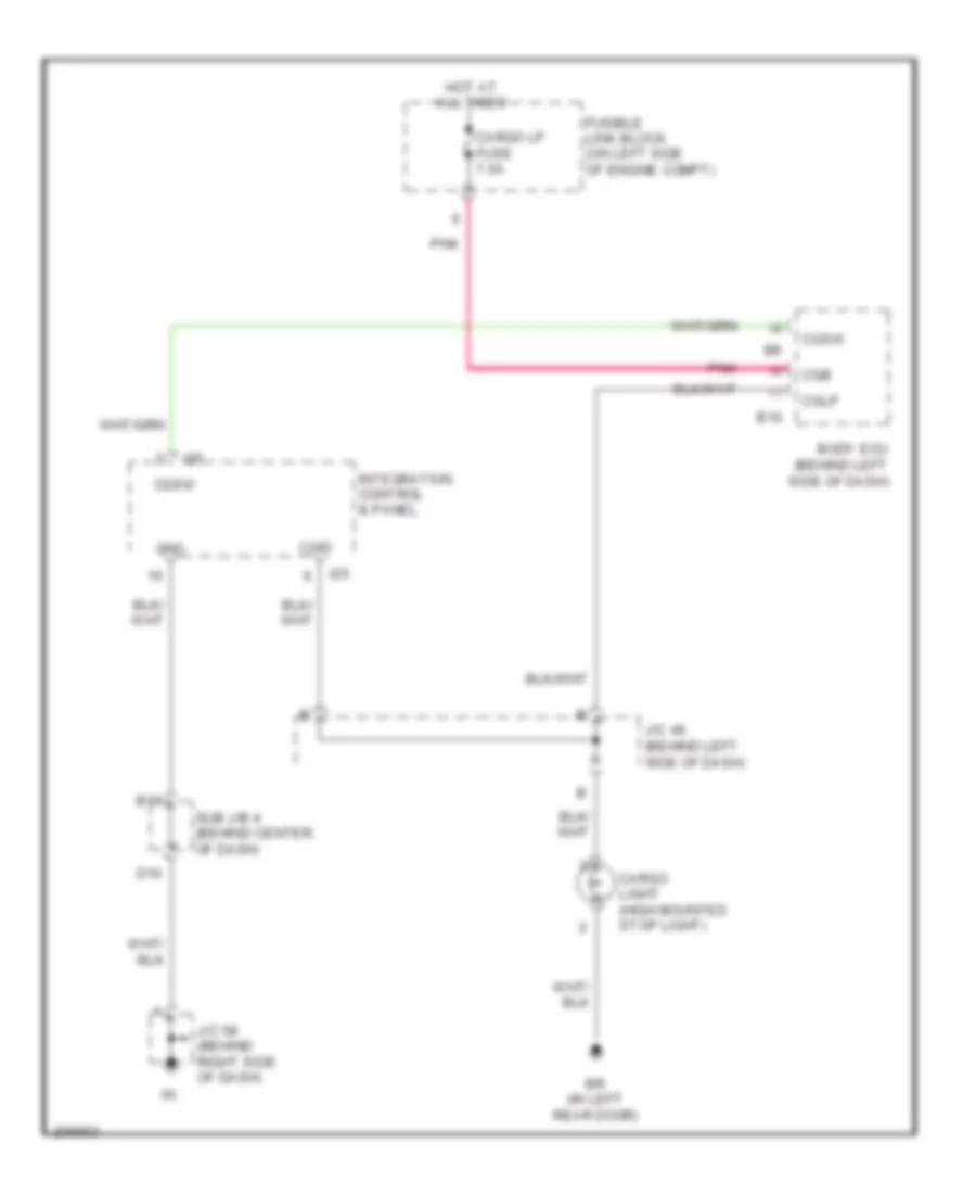
BODY CONTROL MODULES
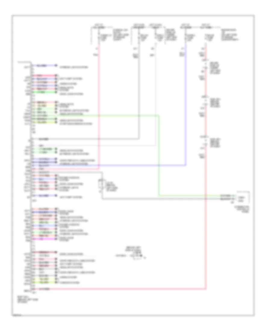
Body ECU Wiring Diagram, Double Cab for Toyota Tundra SR5 2006
List of elements for Body ECU Wiring Diagram, Double Cab for Toyota Tundra SR5 2006:
- (behind left side of dash) j/c 45
- A10
- A19
- Acc
- Act+
- Act-
- Actd
- Acty
- Altl
- Anti-theft system
- B10
- B11
- Bdr
- Becu
- Body ecu (behind left side of dash)
- Bzr
- Cargo lp fuse 7.5a
- Cgb
- Cgid
- Cglp
- Cgsw
- Computer data lines system
- D10
- Dcty
- Dim
- Door 2 fuse 30a
- Door locks system
- Dop
- Driver side j/b (under left end of dash)
- Ecu-b fuse 7.5a
- Ecu-ig fuse 10a
- Engine room j/b (on left side of engine compartment)
- Exterior lights system
- Ffog
- Fusible link block (on left side of engine compt)
- G11
- Gnd
- H-on
- Hcty
- Head
- Headlights system
- Hind
- Horn
- Horns system
- Hot at all times
- Hot in acc or on
- Hot in on or start
- Hrly
- I25
- Ile
- Ind
- Integration control & panel
- Interior lights system
- J/c 46 (behind left side of dash)
- Ksw
- Ksw2
- Lswl
- Lswr
- Mpx1
- Mpx2
- Mpx3
- Obd2
- Pcty
- Pkb
- Pnk
- Power windows system
- Prg
- Rad 2 fuse 7.5a
- Rda
- Rlcy
- Rld
- Rlu
- Rrcy
- Rrd
- Rru
- Starting/charging system
- Sub j/b 3 (behind center of dash)
- Sub j/b 4 (behind center of dash)
- Tail
- Trly
- Warning system
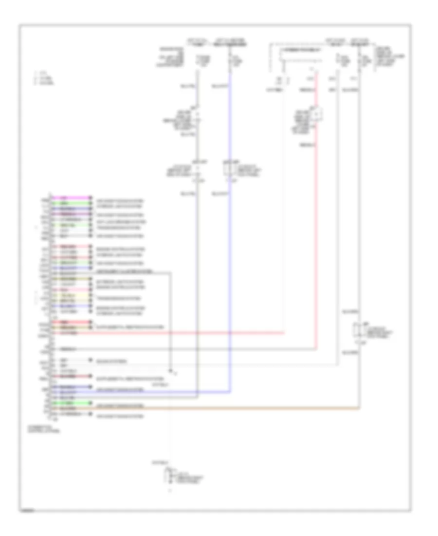
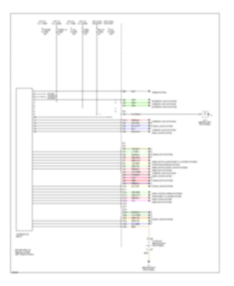
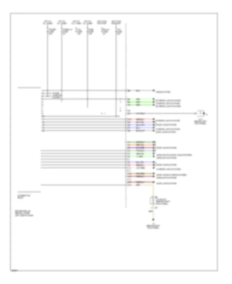
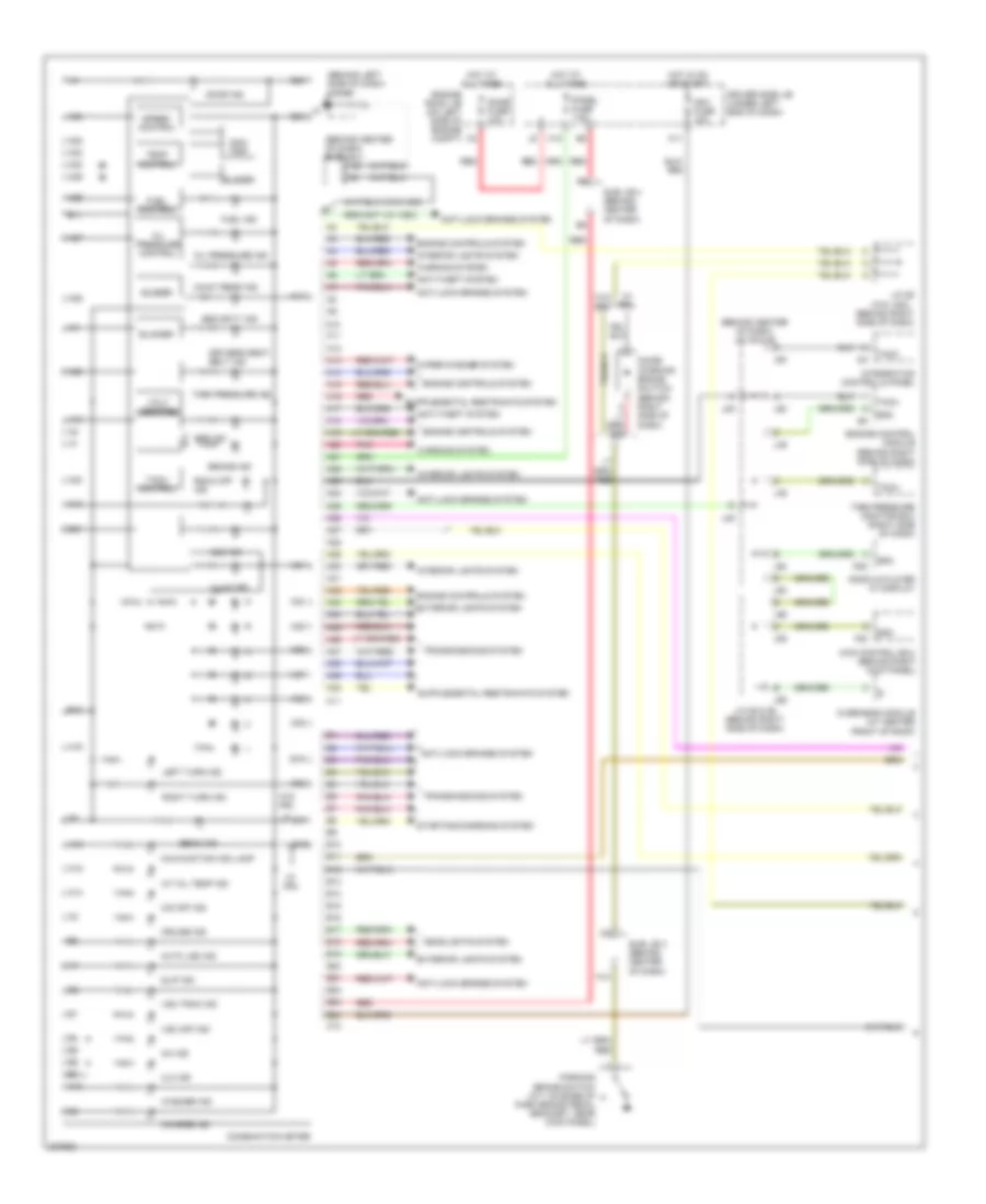
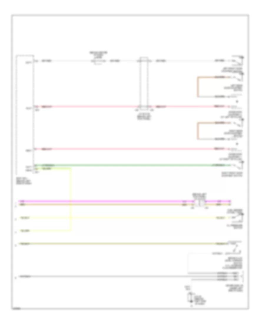
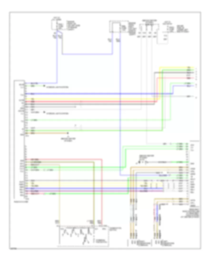
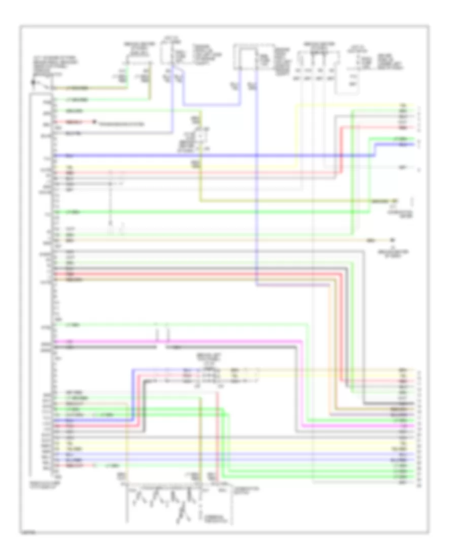
Integration Control and Panel Wiring Diagram, Access/Standard Cab for Toyota Tundra SR5 2006
List of elements for Integration Control and Panel Wiring Diagram, Access/Standard Cab for Toyota Tundra SR5 2006:
- 2-4
- 4.7l
- 4wd
- A/c fuse 10a
- Ac1
- Acc
- Acc fuse 15a
- Acc1
- Act
- Air conditioning system
- Anti-lock brakes system
- Cgid
- Cgsw
- Cpu
- Def
- Dome fuse 10a
- Driver side j/b (behind lower left side of dash)
- Engine controls system
- Engine room r/b (on left side of engine compartment)
- Exterior lights system
- F11
- Frs
- G10
- H-l
- H10
- Haz
- Hot at all times
- Hot in acc or on
- Hot in on or start
- Hot w/ heater relay energized
- I24
- I25
- Ig+
- Ign fuse 5a
- Il-
- Ill+
- Ill-
- Instrument cluster system
- Integration control & panel
- Integration relay
- Interior lights system
- J/c 13 (behind right kick panel)
- J/c 23 & 24 (behind left end of dash)
- J/c 26 & 27 (behind left kick panel)
- J/c 66 & 67 (behind right kick panel)
- J23
- J24
- J26
- J27
- J66
- J67
- L10
- Lms
- Lock
- P-ab
- Paon
- Pbkl
- Pnk
- Pre
- Rec
- Red
- Sg-1
- Sg-2
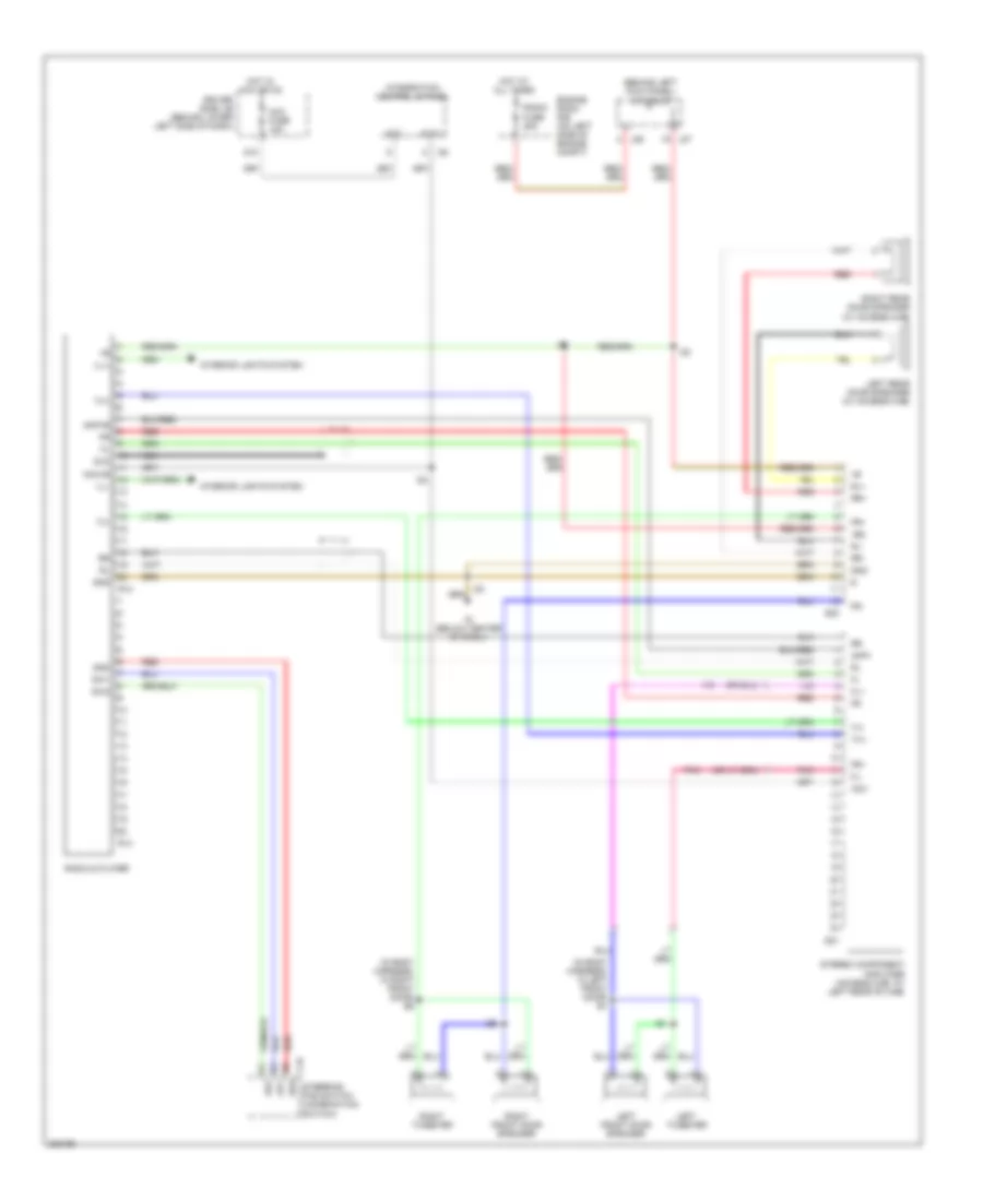
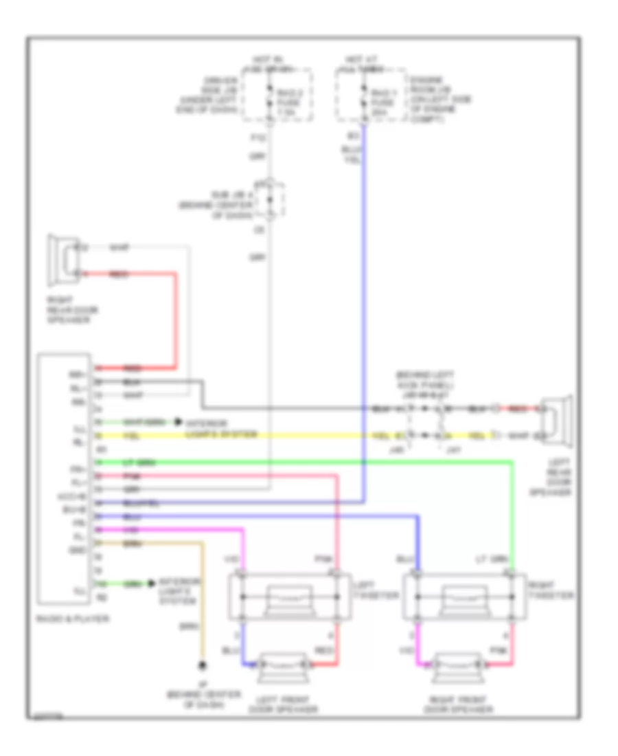
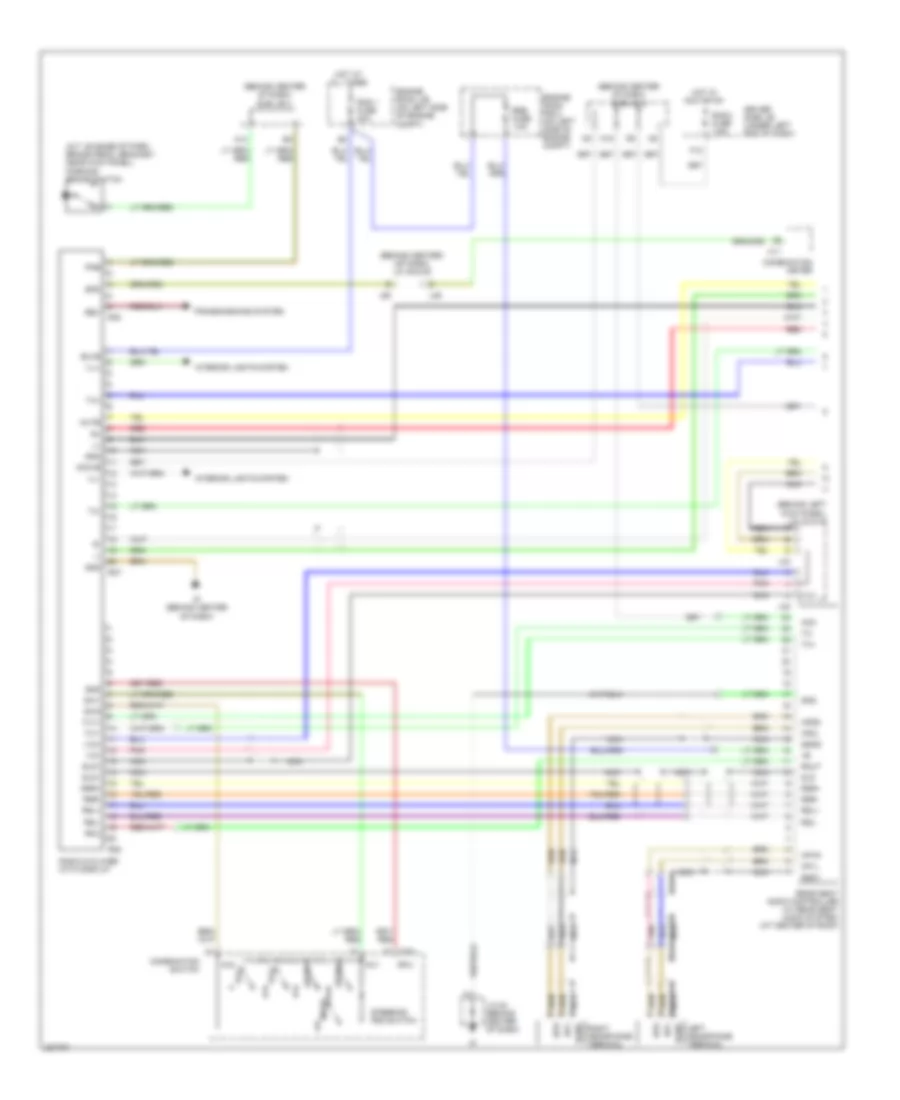
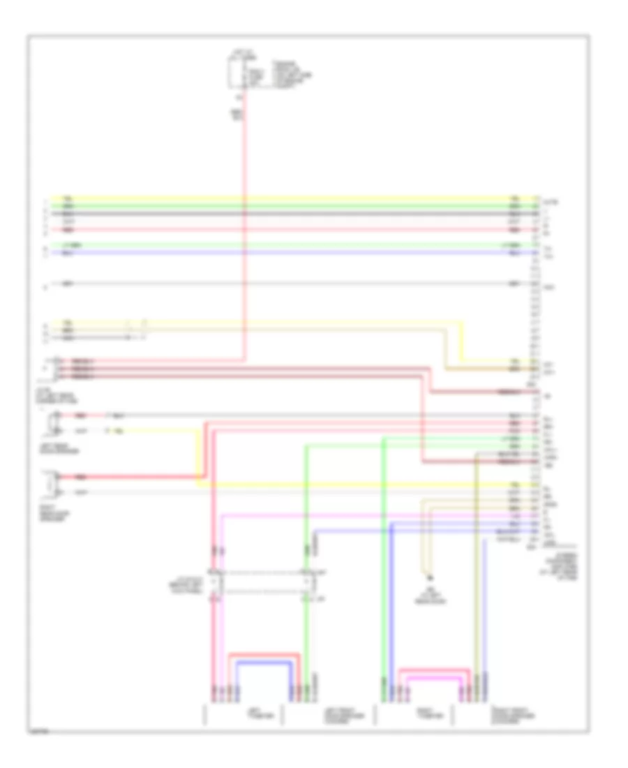
- Sound systems
- Tach
- Transmissions system
- Ver1
- W/ drl
- W/o drl
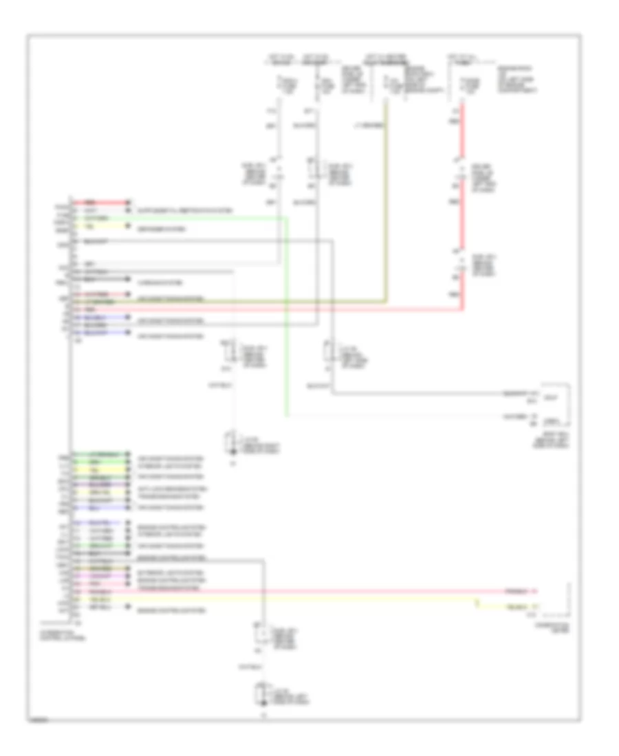
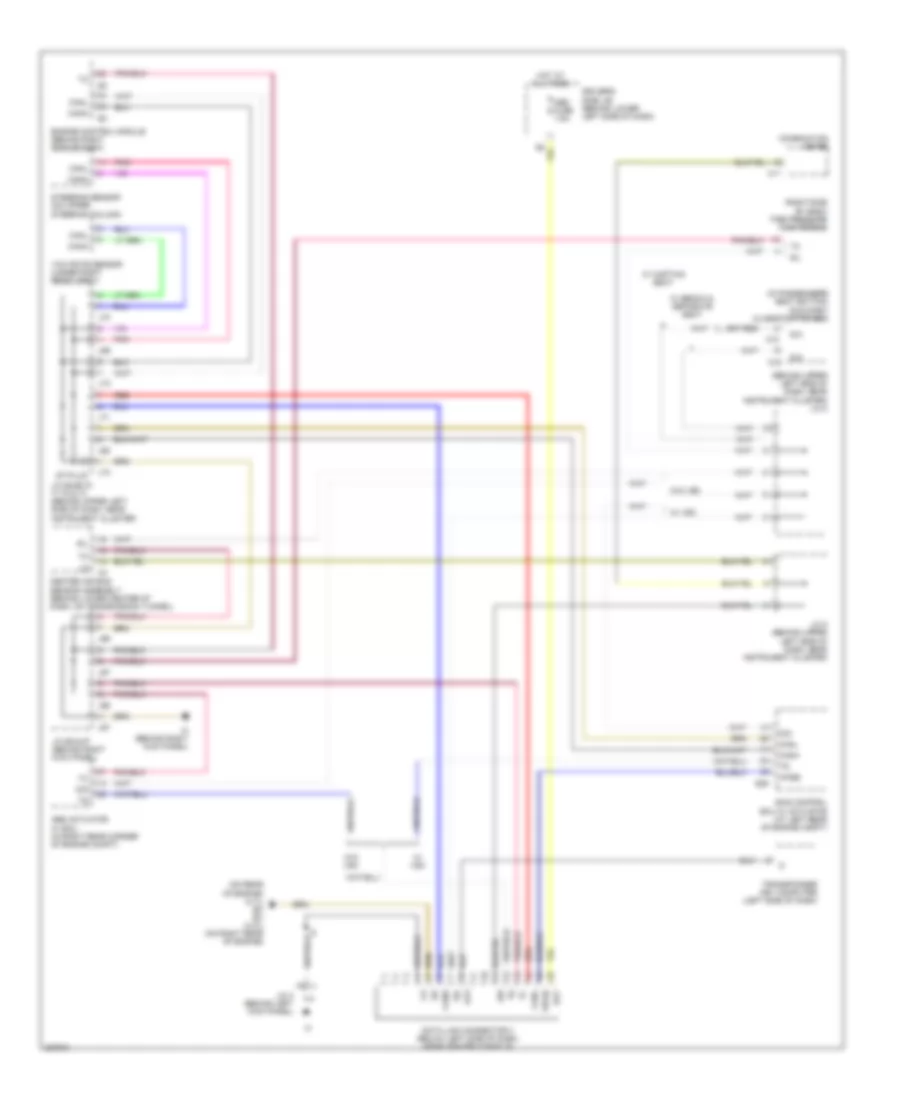
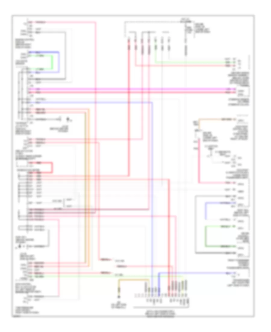
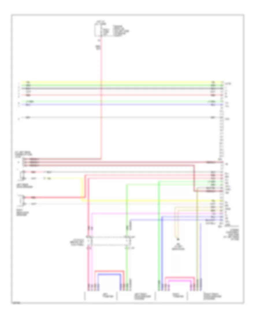
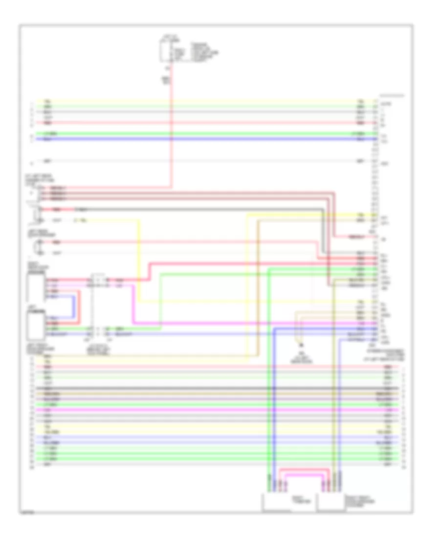
Integration Control and Panel Wiring Diagram, Double Cab for Toyota Tundra SR5 2006
List of elements for Integration Control and Panel Wiring Diagram, Double Cab for Toyota Tundra SR5 2006:
- 2-4
- 4wd
- A/c fuse 7.5a
- Ac1
- Acc
- Act
- Air conditioning system
- Anti-lock brakes system
- B10
- Body ecu (behind left side of dash)
- C12
- Cgid
- Cglp
- Cgsw
- Combination meter
- Cpu
- D10
- Def
- Defogger system
- Dome fuse 10a
- Driver side j/b (under left end of dash)
- E17
- Engine controls system
- Engine room j/b (on left side of engine compartment)
- Engine room r/b 2 (on left side of engine compt)
- Exterior lights system
- F12
- Frs
- H-l
- Haz
- Hot at all times
- Hot in on or acc
- Hot in on or start
- Hot w/ heater relay energized
- I24
- I25
- Ig+
- Ign1 fuse 10a
- Ill+
- Ill-
- Integration control & panel
- Interior lights system
- J/c 45 (behind left side of dash)
- J/c 46 (behind left side of dash)
- J/c 58 (behind right side of dash)
- Lms
- Lock
- P-ab
- Paon
- Pbkl
- Pnk
- Pre
- Rad 2 fuse 7.5a
- Rdef
- Rec
- Red
- Sg-1
- Sg-2
- Sub j/b 3 (behind center of dash)
- Sub j/b 4 (behind center of dash)
- Taco
- Transmissions system
- Ver1
- Warning system
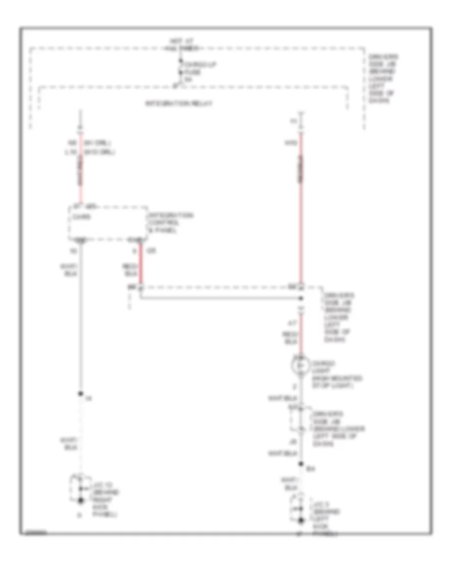
Integration Relay Wiring Diagram, Access/Standard Cab with DRL for Toyota Tundra SR5 2006
List of elements for Integration Relay Wiring Diagram, Access/Standard Cab with DRL for Toyota Tundra SR5 2006:
- Cargo lp fuse 5a
- Door locks & horns systems
- Door locks system
- Driver side j/b (behind lower left side of dash)
- Ecu ig fuse 5a
- Exterior lights system
- F j66
- H j67
- H10
- Headlights & door locks systems
- Headlights & instrument cluster systems
- Headlights system
- Horn fuse 10a
- Horns system
- Hot at all times
- Hot in on or start
- Ih (behind right kick panel)
- Instrument cluster system
- Integration relay
- Interior lights system
- J/c 3 (behind left kick panel)
- J/c 66 & 67 (behind right kick panel)
- N10
- N11
- N12
- N13
- N14
- N15
- N16
- N17
- N18
- N19
- N20
- N21
- N22
- N23
- N24
- Pnk
- Power fuse 30a
- Power windows system
- Red
- Starting/charging system
- Tail fuse 15a
- Wip fuse 20a
Integration Relay Wiring Diagram, Access/Standard Cab without DRL for Toyota Tundra SR5 2006
List of elements for Integration Relay Wiring Diagram, Access/Standard Cab without DRL for Toyota Tundra SR5 2006:
- Cargo lp fuse 5a
- Door locks & horns systems
- Door locks system
- Driver side j/b (behind lower left side of dash)
- Ecu ig fuse 5a
- Exterior lights system
- F j66
- H j67
- H10
- Headlights & door locks systems
- Headlights system
- Horn fuse 10a
- Horns system
- Hot at all times
- Hot in on or start
- Ih (behind right kick panel)
- Integration relay
- Interior lights system
- J/c 3 (behind left kick panel)
- J/c 66 & 67 (behind right kick panel)
- L10
- L11
- L12
- L13
- L14
- L15 l15
- L16
- Power fuse 30a
- Power windows system
- Tail fuse 15a
- Wip fuse 20a
COMPUTER DATA LINES
Computer Data Lines Wiring Diagram, Access/Standard Cab for Toyota Tundra SR5 2006
List of elements for Computer Data Lines Wiring Diagram, Access/Standard Cab for Toyota Tundra SR5 2006:
- (behind upper left side of dash, near instrument cluster) j/c 8
- (in passenger's seat bottom) occupant classification ecu
- (on rear of engine) (4.7l) ec eu (4.ol) (on right rear of engine)
- (right side of dash) tire pressure monitor ecu
- A/b
- Abs actuator w/ ecu (in right rear corner of engine compt)
- Bat
- C11
- Canh
- Canl
- Center air bag sensor assembly (behind lower center of dash, on transmission tunnel)
- Combination meter
- D/g
- Data link connector 3 (below left side of dash, near center console)
- Dia
- Driver's side j/b (behind lower left side of dash)
- Engine control module (behind right side of dash)
- Hot at all times
- Ih (behind right kick panel)
- J/c 3 (behind left kick panel)
- J/c 5 (behind upper left side of dash, near instrument cluster)
- J/c 66 & 67 (behind right kick panel)
- J/c 68,69,70 71,72 & 73 (behind upper left side of dash, near instrument cluster)
- J66
- J67
- J68
- J69
- J70
- J71
- J72
- J73
- O10
- O16
- Obd fuse 7.5a
- Op3
- Pnk
- Red
- S29
- Sil
- Skid control ecu w/ actuator (at left rear of engine compt)
- St-plug
- Steering sensor (on upper steering column)
- Transponder key computer (left side of dash)
- W/ bench & separate seat
- W/ captain seat
- W/ vsc
- W/o vsc
- Wfse
- Yaw rate sensor (under right front seat)
Computer Data Lines Wiring Diagram, Double Cab for Toyota Tundra SR5 2006
List of elements for Computer Data Lines Wiring Diagram, Double Cab for Toyota Tundra SR5 2006:
- A/b
- A17
- A18
- Abs actuator w/ ecu (in right rear corner of engine compt)
- B10
- B11
- Bat
- Body ecu (behind left side of dash)
- C11
- Canh
- Canl
- Center air bag sensor assembly (behind lower center of dash, on transmission tunnel)
- Combination meter
- D/g
- Data link connector 3 (below left side of dash, near center console)
- Dia
- Driver door ecu (in driver's door)
- Driver side j/b (under left end of dash)
- E14
- Ec (on left side of firewall)
- Engine control module (behind right side of dash)
- F13
- F15
- Front passenger door ecu (in front passenger's door)
- G12
- Hot at all times
- J/c 45 (behind left side of dash)
- J/c 54 (behind center of dash)
- J/c 76,77,78, 79,80 & 81 (behind right side of dash)
- J76
- J77
- J78
- J79
- J80
- J81
- K10
- Moon roof control ecu & motor (if equipped) (at center front of roof)
- Mpx1
- Mpx2
- Mpx3
- O10
- O16
- Obd fuse 7.5a
- Obd2
- Occupant classification ecu (under front passenger's seat)
- Op3
- Pnk
- Red
- S29
- Sil
- Skid control ecu w/ actuator (at left rear of engine compartment)
- St-plug
- Steering sensor (on upper steering column)
- Sub j/b 3 (behind center of dash)
- T19
- Tire pressure monitor ecu (right side of dash)
- Transponder key computer (left side of dash)
- W/ captain seat
- W/ separate seat
- W/ vsc
- W/o vsc
- Wfse
- Yaw rate sensor
CRUISE CONTROL
Cruise Control Wiring Diagram, Access/Standard Cab for Toyota Tundra SR5 2006
List of elements for Cruise Control Wiring Diagram, Access/Standard Cab for Toyota Tundra SR5 2006:
- (4.0l: m/t)
- (behind right kick panel)
- (behind right kick panel) ih
- (behind upper left side of dash, near instrument cluster) (a/t) diode
- (behind upper left side of dash, near instrument cluster) j/c 10
- (behind upper left side of dash, near instrument cluster) j/c 8
- (behind upper left side of dash, near instrument cluster) j/c 9
- (behind upper right side of dash, near passenger's air bag)
- (except 4.0l: m/t)
- (on bracket, above brake pedal) stop light switch
- (on left front fender) ea
- (on right rear of engine) (4.0l) eu
- (on transmission)
- (on transmission) park/neutral position switch
- +b2
- +bm
- +res
- -set
- Acc fuse 15a
- Accelerator pedal position sensor (behind left side of dash, above accelerator pedal)
- Batt
- C11
- C12
- C16
- Cancel
- Ccs
- Combination meter
- Cruise control switch (combination switch)
- Cruise ind
- Driver's side j/b (behind lower left side of dash)
- E01
- E02
- Ec (4.7l) (on rear of engine)
- Ecc
- Efi 1 fuse 20a
- Efi relay
- Engine control module (behind right side of dash)
- Engine room r/b (on left side of engine compt)
- Epa
- Epa2
- Etcs fuse 10a
- Eu (4.0l) (on right rear of engine)
- Ew (4.7l) (top left side of engine)
- F10
- F11
- G11
- Gauge fuse 10a
- Ge01
- Hot at all times
- Hot in acc or on
- Hot in on or start
- I3 (in dash harness, behind right side of dash)
- Ign fuse 5a
- Igsw
- J/c 1 (under engine room r/b)
- J/c 18 (under engine room r/b)
- J/c 26 & 27 (behind left kick j27 panel)
- J/c 28 & 29
- J/c 28 & 29 (behind upper right side of dash, near passenger's air bag)
- J/c 66 & 67
- J/c 66 (behind right kick panel)
- J26
- J28
- J29
- J66
- J67
- Mrel
- On/off
- Spd
- Speed control
- St1-
- Stop fuse 15a
- Stop light relay (w/vsc) (behind left side of dash)
- Stp
- Throttle control motor & position sensor (on throttle body)
- Vcp2
- Vcpa
- Vehicle speed sensor (combination meter) (m/t)
- Vpa
- Vpa2
- Vta1
- Vta2
- W/o vsc
Cruise Control Wiring Diagram, Double Cab for Toyota Tundra SR5 2006
List of elements for Cruise Control Wiring Diagram, Double Cab for Toyota Tundra SR5 2006:
- (behind left side of dash) j/c 47 & 48
- (left side of engine) ey
- (on bracket, above brake pedal) stop light switch
- +b2
- +bm
- +res
- -set
- Accelerator pedal position sensor (behind left side of dash, above accelerator pedal)
- Batt
- C11
- C12
- C16
- Cancel
- Ccs
- Combination meter
- Cruise control switch (combination switch)
- Cruise ind
- Driver side j/b (under left end of dash)
- E01
- E02
- Ea (on left front fender)
- Ec (on left side of firewall)
- Ecc
- Efi 1 fuse 20a
- Efi relay
- Engine control module (behind right side of dash)
- Engine room j/b (on left side of engine compt)
- Epa
- Epa2
- Etcs fuse 10a
- Gauge fuse 15a
- Ge01
- Hot at all times
- Hot in on or start
- I1 (in dash harness, behind upper right end of dash)
- Ign 1 fuse 10a
- Igsw
- Ipo
- J/c 28 & 29 (behind right side of dash)
- J/c 34 (on left side of engine compt, under engine room r/b)
- J/c 45 (behind left side of dash)
- J/c 49 (behind center of dash)
- J/c 75 (behind right side of dash)
- J28
- J29
- J47
- J48
- Mrel
- On/off
- Park/neutral position switch (on transmission)
- Red
- Sp2+
- Sp2-
- Spd
- St1-
- Stop fuse 15a
- Stop light relay (w/ vsc)
- Stp
- Sub j/b 3 (behind center of dash)
- Throttle control motor & position sensor (on throttle body assembly)
- Vcp2
- Vcpa
- Vehicle speed sensor (electronically controlled transmission) (on transmission)
- Vpa
- Vpa2
- Vta1
- Vta2
- W/o vsc
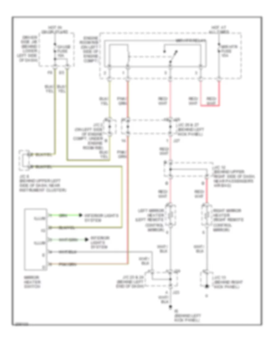
DEFOGGERS
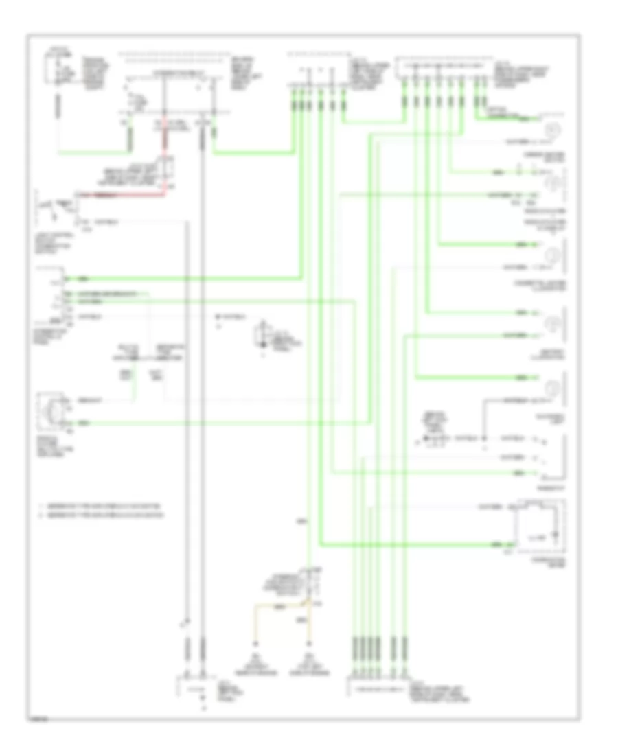
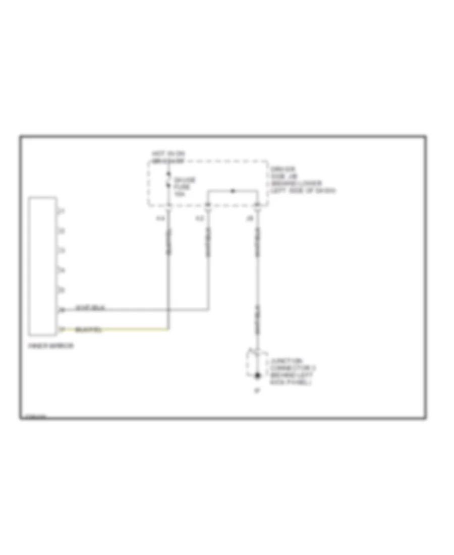
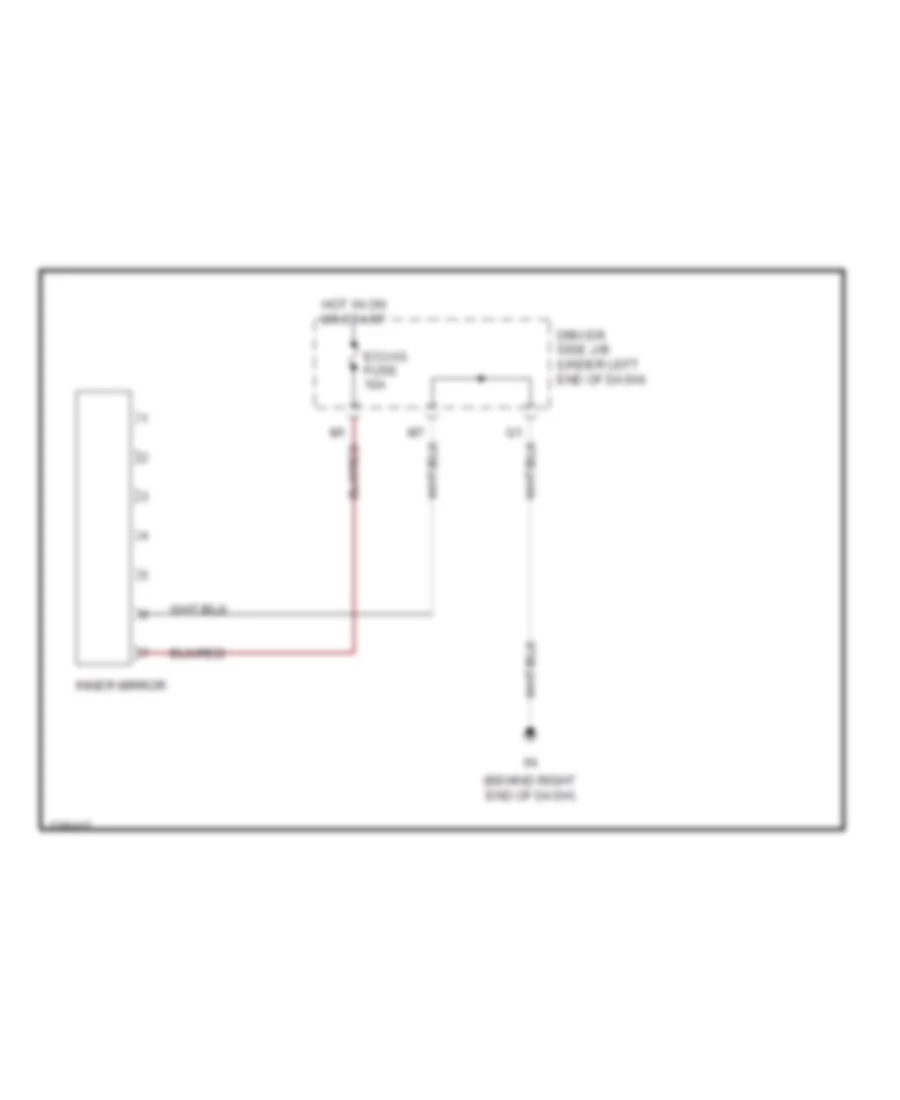
Defoggers Wiring Diagram, Access/Standard Cab for Toyota Tundra SR5 2006
List of elements for Defoggers Wiring Diagram, Access/Standard Cab for Toyota Tundra SR5 2006:
- Control mirror)
- Driver side j/b (behind lower left side of dash)
- Engine room r/b (on left side of engine compt)
- Gauge fuse 10a
- Hot at all times
- Hot in on or start
- Ie (behind left kick panel)
- Illum
- Interior lights system
- J/c 12 (behind upper right side of dash, near passenger's air bag)
- J/c 13 (behind right kick panel)
- J/c 2 (on left side of engine compt, under engine room r/b)
- J/c 23 & 24 (behind left end of dash)
- J/c 26 & 27 (behind left kick panel)
- J/c 8 (behind upper left side of dash, near instrument cluster)
- J23
- J24
- J26
- J27
- Left mirror heater (left remote
- Mir htr fuse 15a
- Mir htr relay
- Mirror heater switch
- Right mirror heater (right remote
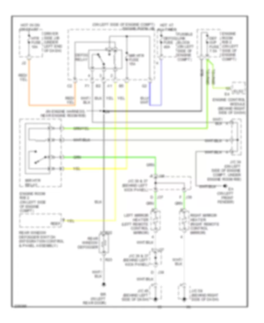
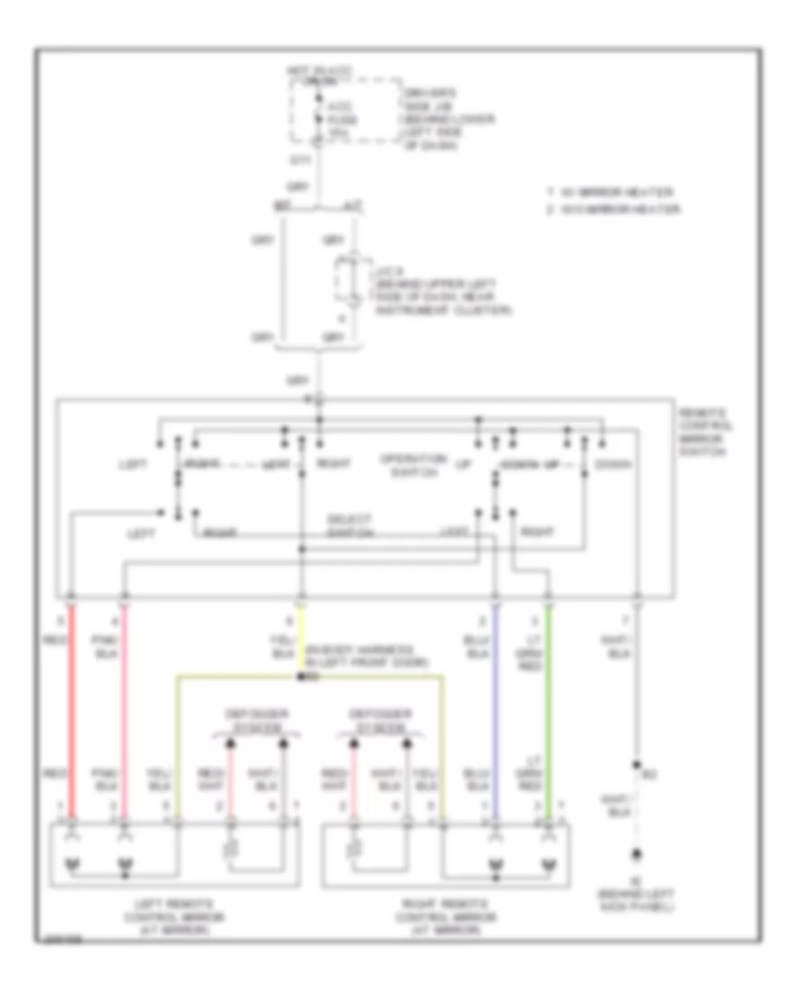
Defoggers Wiring Diagram, Double Cab for Toyota Tundra SR5 2006
List of elements for Defoggers Wiring Diagram, Double Cab for Toyota Tundra SR5 2006:
- (in engine harness, near engine room r/b)
- (on left side of engine compt) engine room j/b
- Br (in left rear door)
- D j36
- D j37
- Def i/up fuse 7.5a
- Defog fuse 40a
- Defog relay
- Driver side j/b (under left end of dash)
- Ea (on left front fender)
- Els2
- Engine control module (behind right side of dash)
- Engine room r/b 2 (on left side of engine compt)
- F j36
- F j37
- Fusible link block (on left side of engine compt)
- Hot at all times
- Hot in on or start
- Htr fuse 10a
- J/c 34 (on left side of engine compt, under engine room r/b)
- J/c 36 & 37 (behind left kick panel)
- J/c 45 (behind left side of dash)
- J/c 58 (behind right side of dash)
- J36
- Left mirror heater (left remote control mirror)
- Mir htr fuse 15a
- Mir htr relay
- R22
- R23
- Rdef
- Rear window defogger
- Rear window defogger switch (integration control & panel assembly)
- Right mirror heater (right remote control mirror)
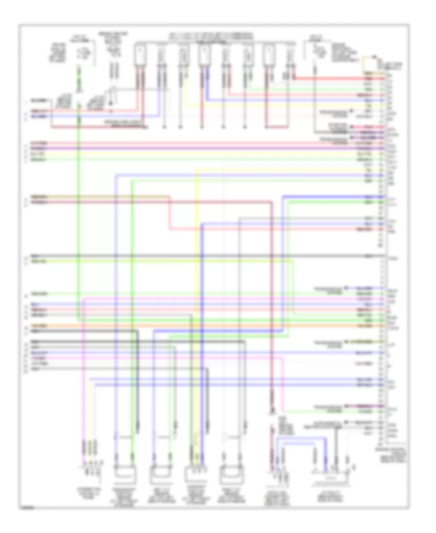
ENGINE PERFORMANCE
4.0L
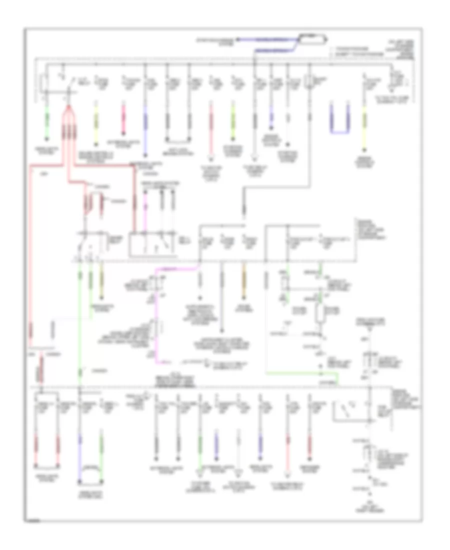
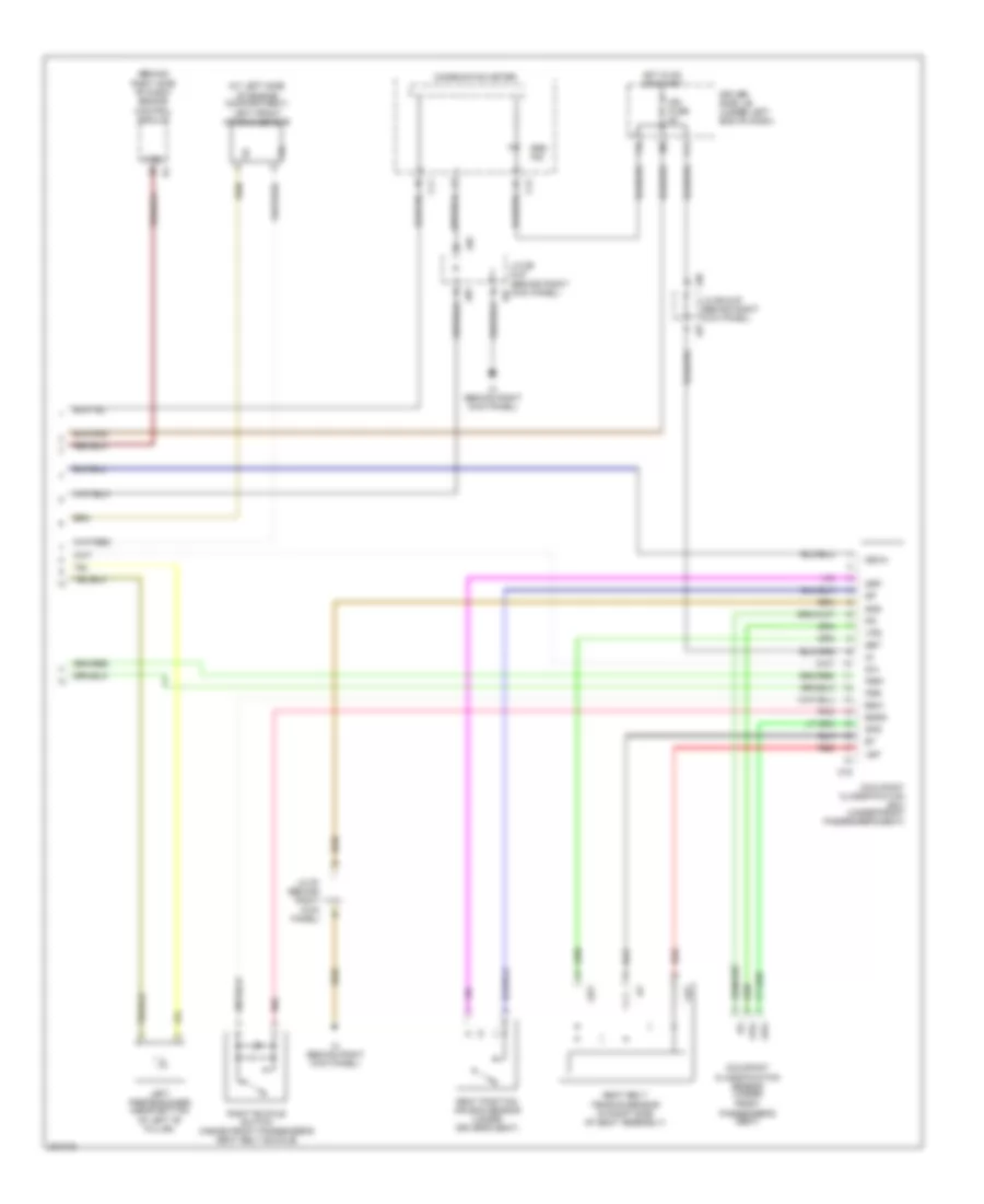
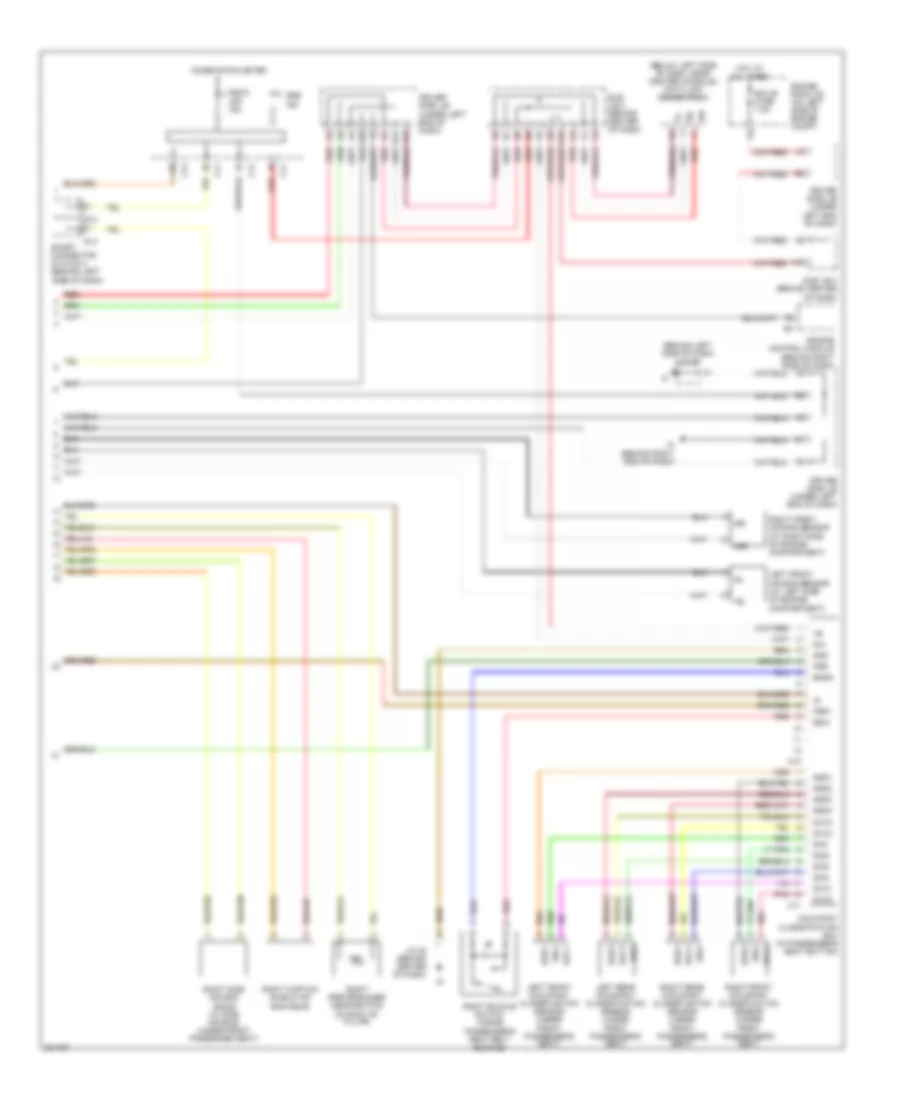
4.0L, Engine Performance Wiring Diagram (1 of 7) for Toyota Tundra SR5 2006
List of elements for 4.0L, Engine Performance Wiring Diagram (1 of 7) for Toyota Tundra SR5 2006:
- (in dash harn, behind upper right side of dash)
- (inside transmission) electronically controlled transmission solenoid
- (on left side of engine) ev
- (on right rear of engine) eu
- +b2
- +bm
- A1a+
- A1a-
- A2a+
- A2a-
- Accr
- Batt
- Cruise control system
- E03
- E04
- E05
- Ekn2
- Eknk
- Engine control module (behind right side of dash)
- Epa
- Epa2
- Ha1a
- Ha2a
- Ht2b
- Igsw
- J/c 26 & 27 (behind left kick panel)
- J26
- J27
- Knk1
- Knk2
- Me01
- Mpmp
- Mrel
- Nsw
- Nt+
- Nt-
- O/d direct clutch speed sensor
- Odms
- Ox2b
- Pnk
- Power distribution system
- Ppmp
- Red
- Sl1
- Sl1+
- Sl1-
- Sl2
- Sl2+
- Sl2-
- Slt
- Slt+
- Slt-
- Slu
- Slu+
- Slu-
- Sp2+
- Sp2-
- Starting/ charging system
- Stp
- Th02
- Tho1
- Trans- missions system
- Vcp2
- Vcpa
- Vehicle speed sensor (electronically controlled transmission) (on transmission)
- Vpa
- Vpa2
- Vpmp
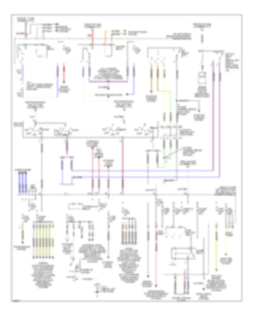
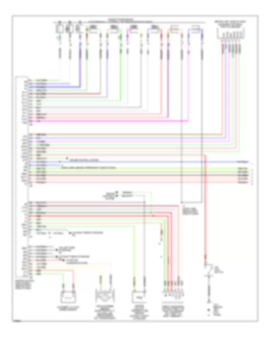
4.0L, Engine Performance Wiring Diagram (2 of 7) for Toyota Tundra SR5 2006
List of elements for 4.0L, Engine Performance Wiring Diagram (2 of 7) for Toyota Tundra SR5 2006:
- (a/t)
- (behind left side of dash) accelerator pedal position sensor
- (behind right kick panel) j/c 66
- (in dash harn, behind right side of dash)
- (m/t)
- (on left side of engine compt) j/c 1
- Af+
- Af-
- Air fuel ratio sensor (bank 1 sensor 1) (on exhaust system)
- Air fuel ratio sensor (bank 2 sensor 1) (on exhaust system)
- Canister pressure sensor
- Canister pump module
- Driver's side j/b (behind lower left side of dash)
- E2g
- Epa
- Epa2
- Eu (on right rear of engine)
- F10
- F11
- Heated oxygen sensor (bank 1 sensor 2) (on exhaust system)
- Heated oxygen sensor (bank 2 sensor 2) (on exhaust system)
- Hot in on or start
- Ign fuse 5a
- J26 j/c 26 & 27 (behind left kick panel)
- J27
- Leak detection pump
- Mass air flow meter (on right side of engine)
- Nca
- Nca a
- Nca b
- Nca c
- Nca d
- Pnk
- Red
- Tha
- To j/c 65 (diagram 4 of 7)
- Vcp2
- Vcpa
- Vent valve
- Vpa
- Vpa2
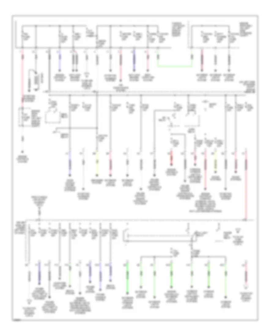
4.0L, Engine Performance Wiring Diagram (3 of 7) for Toyota Tundra SR5 2006
List of elements for 4.0L, Engine Performance Wiring Diagram (3 of 7) for Toyota Tundra SR5 2006:
- (dash harn, behind right side of dash)
- (engine harn, at right front of engine) e11
- (in fuel tank) fuel pump
- (on left side of engine compt) fuel pump resistor
- A/f htr relay
- Acis
- C/opn relay
- E01
- E02
- E2g
- Ea (on left front fender)
- Efi relay
- Engine control module (behind right side of dash)
- Engine room r/b (on left side of engine compt)
- Et (on right side of engine compt)
- Eu (on right rear of engine)
- Fuel pump relay
- Ge01
- Ht1b
- Igf1
- Igt1
- Igt2
- Igt3
- Igt4
- Igt5
- Igt6
- J/c 18 (on left side of engine compt)
- J/c 26 & 27 (behind left kick panel)
- J/c 3 (behind left kick panel)
- J26
- J27
- Nca
- Ox1b
- Prg
- Red
- Tha
- Throttle control motor (on throttle body) throttle position sensor (on throttle body assembly)
- Thw
- Vta
- Vta1
- Vta2
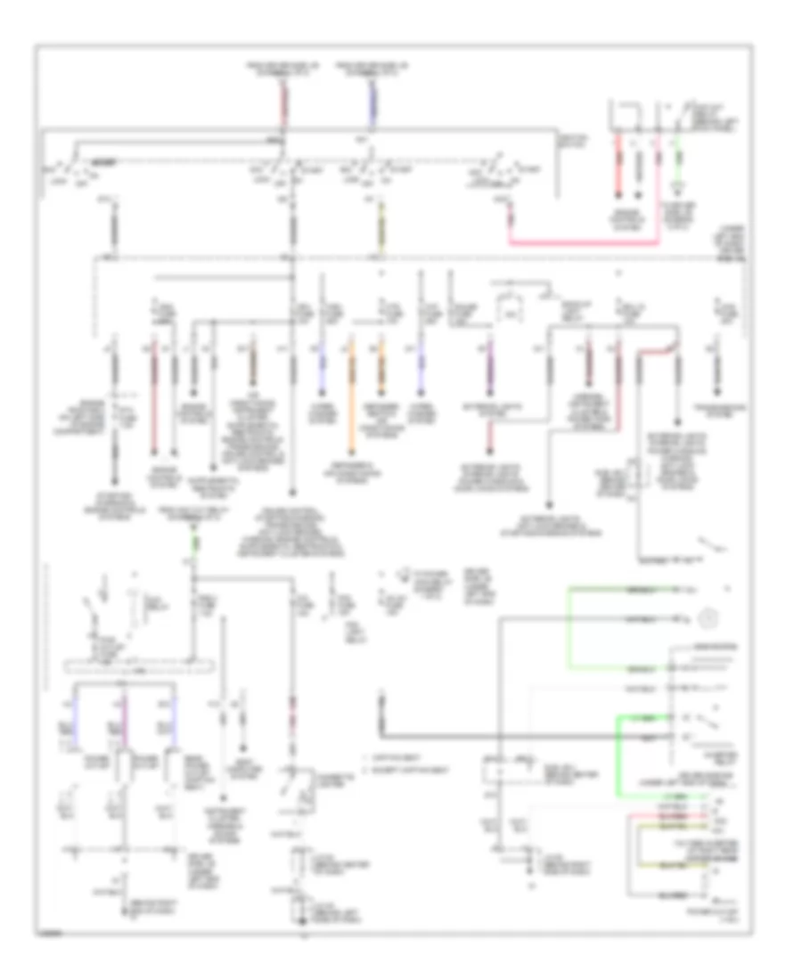
4.0L, Engine Performance Wiring Diagram (4 of 7) for Toyota Tundra SR5 2006
List of elements for 4.0L, Engine Performance Wiring Diagram (4 of 7) for Toyota Tundra SR5 2006:
- (behind upper right side of dash) j/c 65
- (engine harn, at front of engine)
- (on top left
- (on top right
- E14 (engine harn, at rear of engine)
- E17
- Engine coolant temperature sensor (at right rear of engine)
- Ev (on left side of engine)
- From air fuel ratio sensor shields (diagram 2 of 7)
- From heated oxygen sensor shields (diagram 2 of 7)
- Nca
- Power steering oil pressure switch (on right front of engine)
- Red
- Side of engine) knock sensor (bank 1)
- Side of engine) knock sensor (bank 2)
- Vsv (acis)
- Vsv (purge)
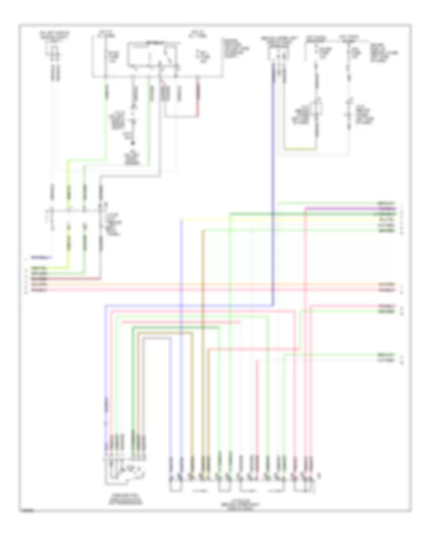
4.0L, Engine Performance Wiring Diagram (5 of 7) for Toyota Tundra SR5 2006
List of elements for 4.0L, Engine Performance Wiring Diagram (5 of 7) for Toyota Tundra SR5 2006:
- (behind upper left side of dash) diode (a/t)
- (engine harn, at rear of engine) e14
- A red
- A/f htr fuse 20a
- Acc fuse 15a
- Driver's side j/b (behind lower left side of dash)
- E14
- E15 (engine harn, right front of engine)
- Efi 1 fuse 20a
- Efi 2 fuse 10a
- Engine room r/b (on left side of engine compt)
- Etcs fuse 10a
- Ev (on left side of engine)
- G11
- Gauge fuse 10a
- Hot at all times
- Hot in on or acc
- Hot in on or start
- Igniter & ignition coil 1 (at top of right cylinder bank)
- Igniter & ignition coil 2 (at top of left cylinder bank)
- Igniter & ignition coil 3 (at top of right cylinder bank)
- Igniter & ignition coil 4 (at top of left cylinder bank)
- Igniter & ignition coil 5 (at top of right cylinder bank)
- Igniter & ignition coil 6 (at top of left cylinder bank)
- J/c 28 & 29 (behind upper right side of dash)
- J/c 8 (behind upper left side of dash)
- J/c 8 (behind upper left side of dash) a red
- J/c 9 (behind upper left side of dash)
- J26
- J26 j/c 26 & 27 (behind left kick panel)
- J27
- J28
- J29
- Noise filter (on top rear of engine)
- Red
- Vehicle speed sensor (combination meter) (m/t) (on transmission)
4.0L, Engine Performance Wiring Diagram (6 of 7) for Toyota Tundra SR5 2006
List of elements for 4.0L, Engine Performance Wiring Diagram (6 of 7) for Toyota Tundra SR5 2006:
- A j28
- A/t
- Acc
- Anti-lock brakes system
- B j28
- C j28
- C11
- C12
- Combination meter
- D j28
- Driver's side j/b (behind lower left side of dash)
- F j28
- G j28
- Hot at all times
- Ignition switch
- Ih (behind right kick panel)
- J/c 28 & 29 (behind upper right side of dash)
- J/c 5 (behind upper left side of dash)
- J/c 66 (behind right kick panel)
- J29
- J66 j/c 66 & 67 (behind right kick panel) j67
- Left camshaft timing oil control valve (top left of engine)
- Lock
- M/t
- Mil ind
- Oil press ctrl
- Park/neutral position switch (on transmission)
- Right camshaft timing oil control valve (top right of engine)
- Run
- Speed ctrl
- Start
- Tach ctrl
- Temp ctrl
- W/ tachometer
- W/o tachometer
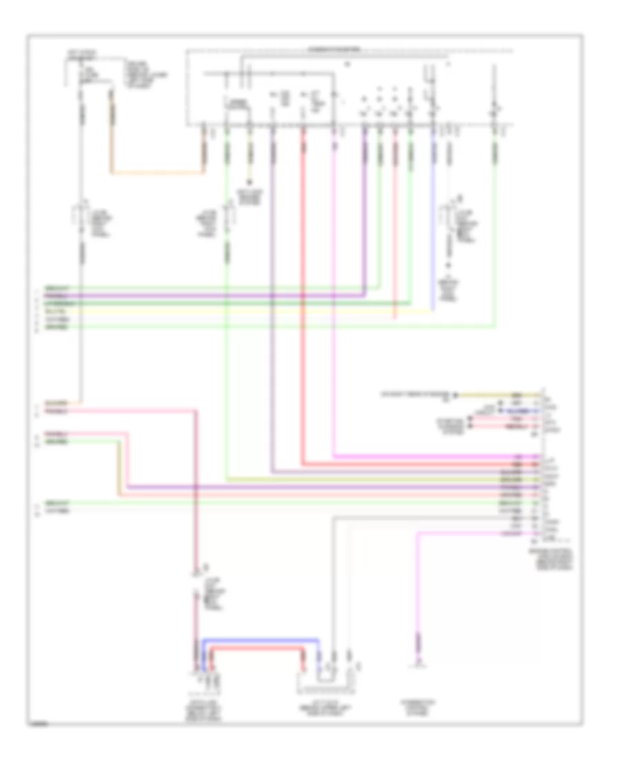
4.0L, Engine Performance Wiring Diagram (7 of 7) for Toyota Tundra SR5 2006
List of elements for 4.0L, Engine Performance Wiring Diagram (7 of 7) for Toyota Tundra SR5 2006:
- (dash harn, behind right side of dash)
- (inj 2, 4 & 6: on left cylinder bank) (inj 1, 3 & 5: on right cylinder bank) fuel injector
- 4wd
- Ac1
- Act
- Canh
- Canl
- Crankshaft position sensor (on left front of engine)
- Data link connector 3 (below left side of dash)
- Driver's side j/b (behind lower left side of dash)
- E18 (engine harn, right side nca
- Elsi
- Engine control module (behind right side of dash)
- Eu (on right rear of engine)
- F/ps
- Fpr
- Hot at all times
- I24
- Integration control & panel
- Integration relay
- J/c 10 (behind upper left side of dash)
- J/c 66 & 67 (behind right kick panel)
- J/c 71 & 72 (behind upper left side of dash)
- J66
- J67
- J71
- J72
- Left vvt sensor (on top left side of engine)
- Llp
- Lms
- Ne+
- Ne-
- Oc1+
- Oc1-
- Oc2+
- Oc2-
- Odlp
- Of engine)
- Oilw
- Pnk
- Psw
- Red
- Right vvt sensor (on top right side of engine)
- Spd
- Sta
- Starting/ charging system
- Stsw
- Tach
- Tail fuse 15a
- Thwo
- Transmissions system
- Vv1+
- Vv1-
- Vv2+
- Vv2-
4.7L
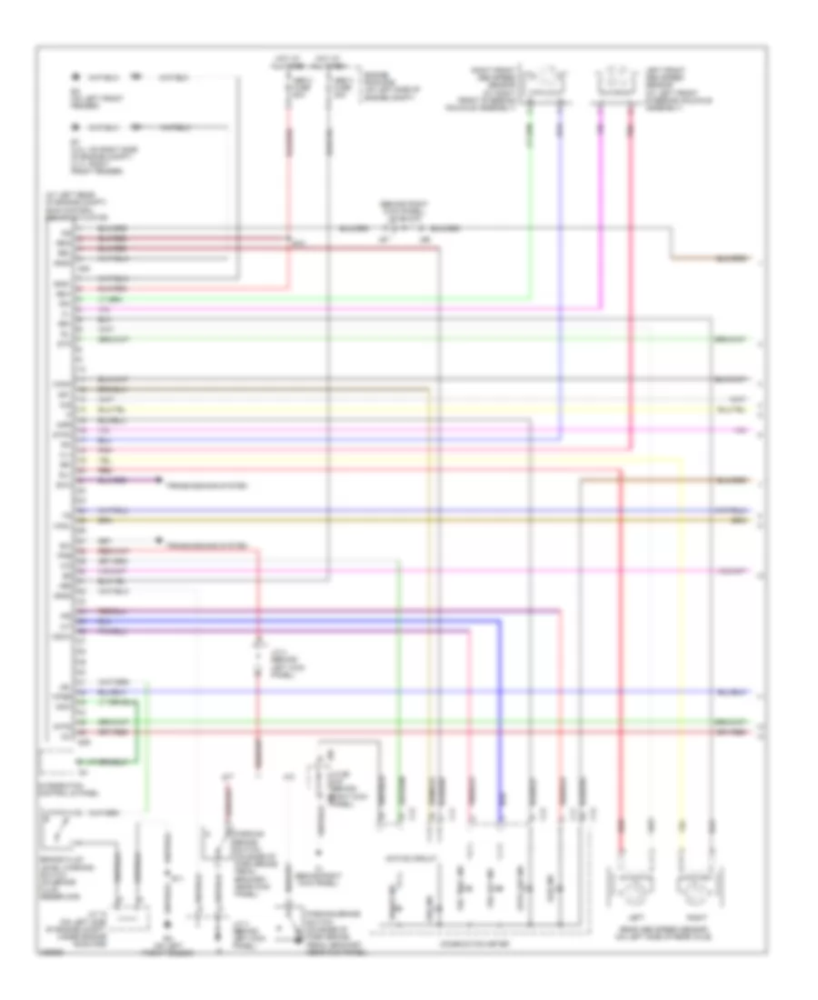
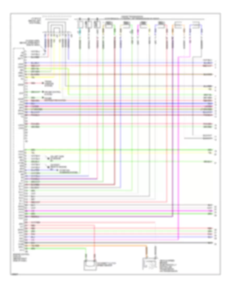
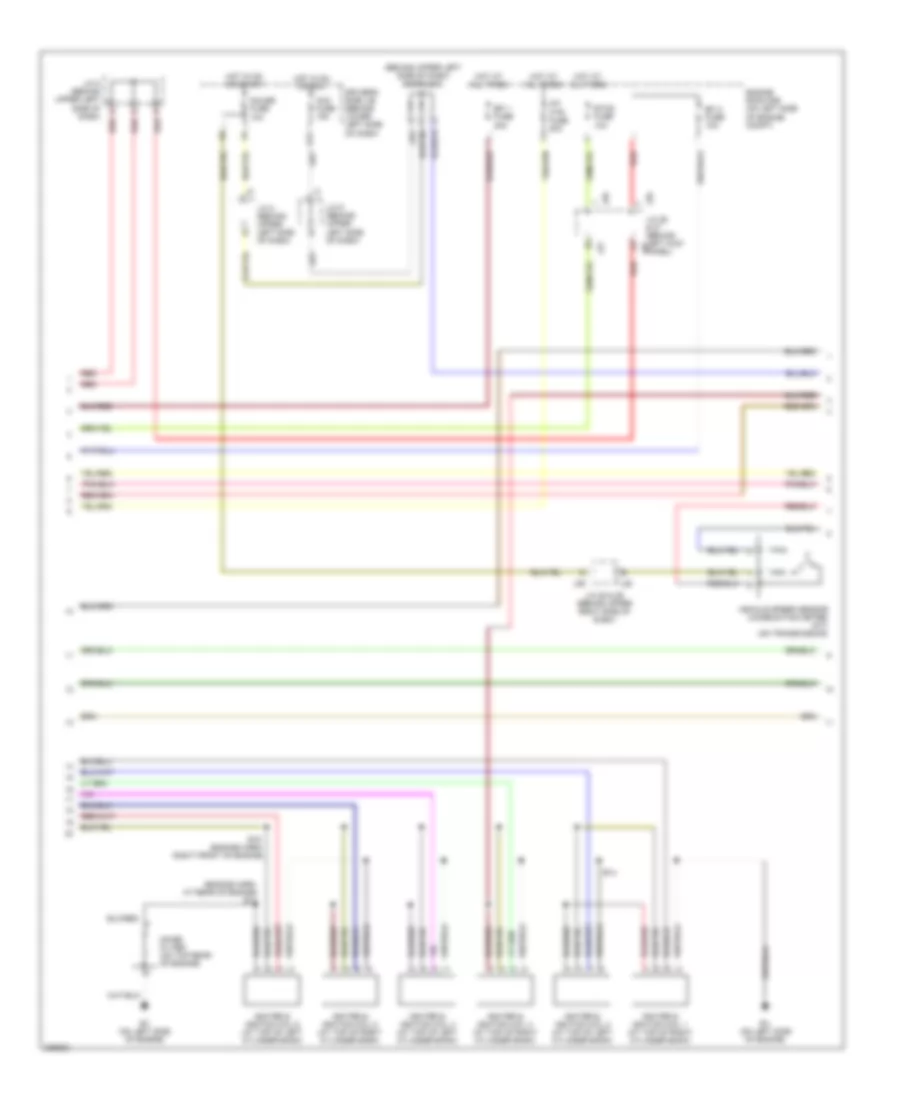
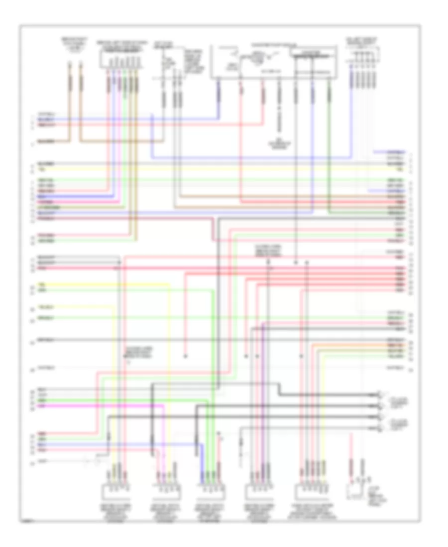
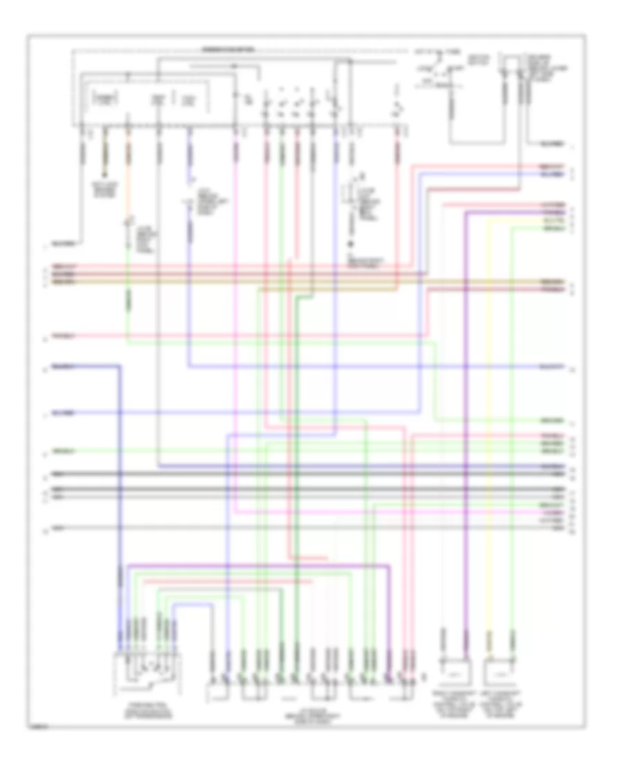
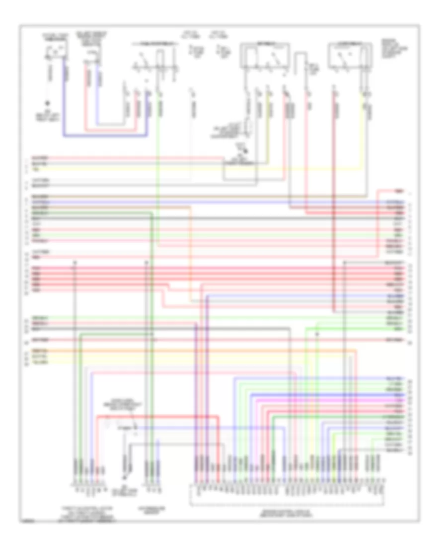
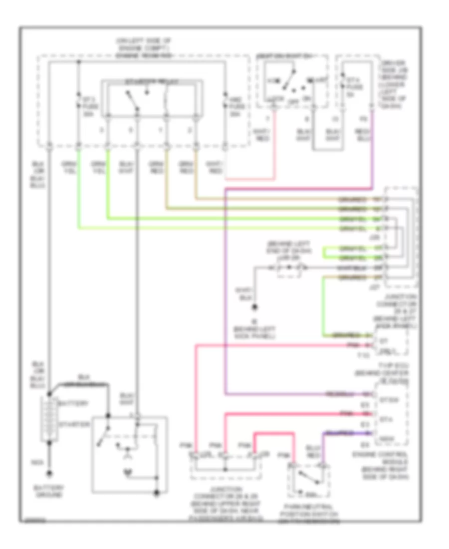
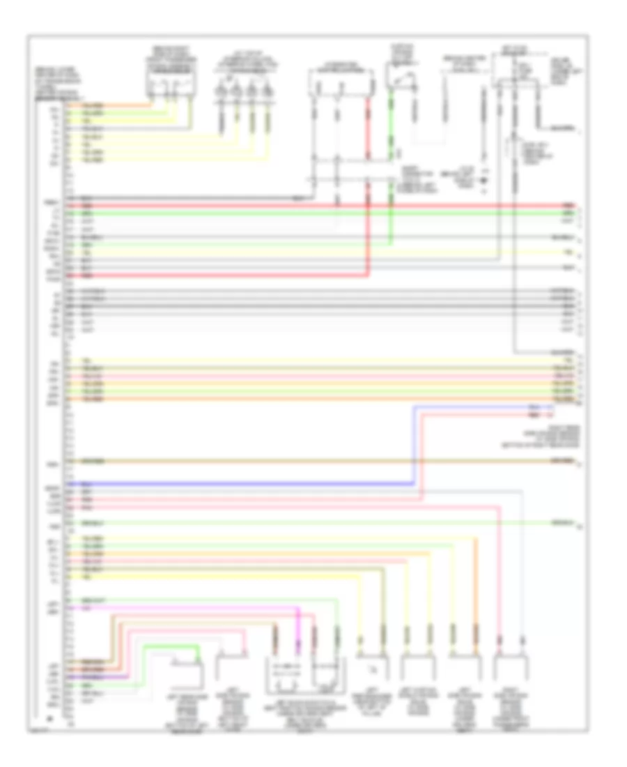
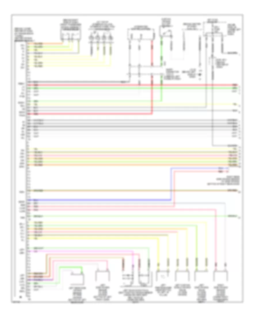
4.7L, Engine Performance Wiring Diagram, Access/Standard Cab (1 of 7) for Toyota Tundra SR5 2006
List of elements for 4.7L, Engine Performance Wiring Diagram, Access/Standard Cab (1 of 7) for Toyota Tundra SR5 2006:
- (in dash harn, behind upper right side of dash)
- (inside transmission) electronically controlled transmission solenoid
- (on rear of engine) ec
- (top left side of engine) ew
- +b2
- +bm
- A1a+
- A1a-
- A2a+
- A2a-
- Accr
- Aidi
- Airp
- Airv
- Batt
- Cruise control system
- E03
- E04
- E05
- Ec (on rear of engine)
- Ekn2
- Eknk
- Engine control module (behind right side of dash)
- Epa
- Epa2
- Ha1a
- Ha2a
- Ht2b
- Igsw
- J/c 26 & 27 (behind left kick panel)
- J26
- J27
- Knk1
- Knk2
- Me01
- Mpmp
- Mrel
- Nsw
- Nt+
- Nt-
- O/d direct clutch speed sensor (on left side of transmission)
- Odms
- Ox2b
- Pnk
- Power distribution system
- Ppmp
- Red
- Sl1
- Sl1+
- Sl1-
- Sl2
- Sl2+
- Sl2-
- Slt
- Slt+
- Slt-
- Slu
- Slu+
- Slu-
- Sp2+
- Sp2-
- Starting/ charging system
- Stp
- Th02
- Tho1
- Trans- missions system
- Vcp2
- Vcpa
- Vehicle speed sensor (electronically controlled transmission) (on transmission)
- Vpa
- Vpa2
- Vpmp
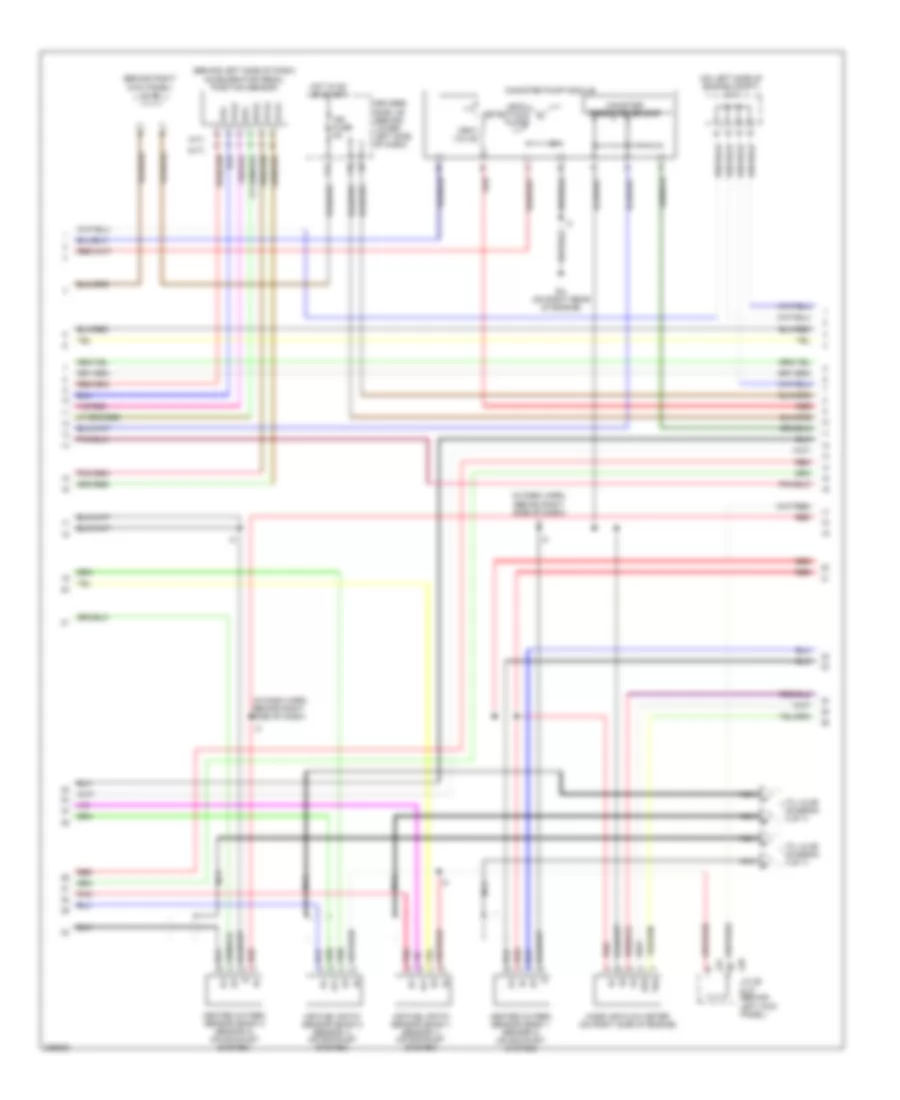
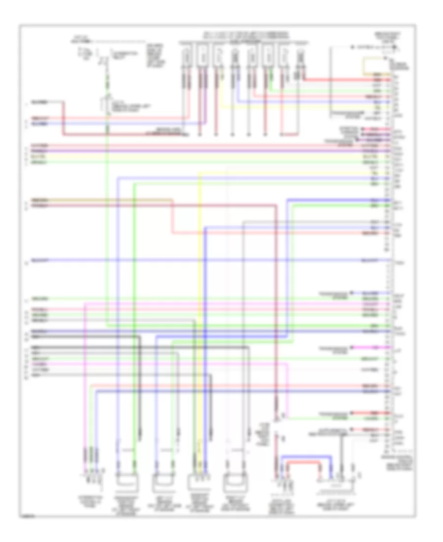
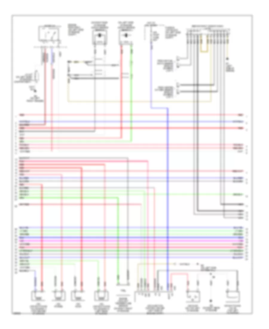
4.7L, Engine Performance Wiring Diagram, Access/Standard Cab (2 of 7) for Toyota Tundra SR5 2006
List of elements for 4.7L, Engine Performance Wiring Diagram, Access/Standard Cab (2 of 7) for Toyota Tundra SR5 2006:
- (behind left side of dash) accelerator pedal position sensor
- (behind right kick panel) j/c 66
- (in dash harn, behind right side of dash)
- (on left side of engine compt) j/c 1
- Af+
- Af-
- Air fuel ratio sensor (bank 1 sensor 1) (on top left of engine)
- Air fuel ratio sensor (bank 2 sensor 1) (on exhaust system)
- Canister pressure sensor
- Canister pump module
- Driver's side j/b (behind lower left side of dash)
- E2g
- Ec (on rear of engine)
- Epa
- Epa2
- F10
- F11
- Heated oxygen sensor (bank 1 sensor 2) (on exhaust system)
- Heated oxygen sensor (bank 2 sensor 2) (on exhaust system)
- Hot in on or start
- Ign fuse 5a
- J26 j/c 26 & 27 (behind left kick panel)
- J27
- Leak detection pump
- Mass air flow meter (on right side of engine compartment, on air cleaner housing)
- Nca
- Nca a
- Nca b
- Nca c
- Nca d
- Pnk
- Red
- Tha
- To j/c 64 (diagram 4 of 7)
- Vcp2
- Vcpa
- Vent valve
- Vpa
- Vpa2
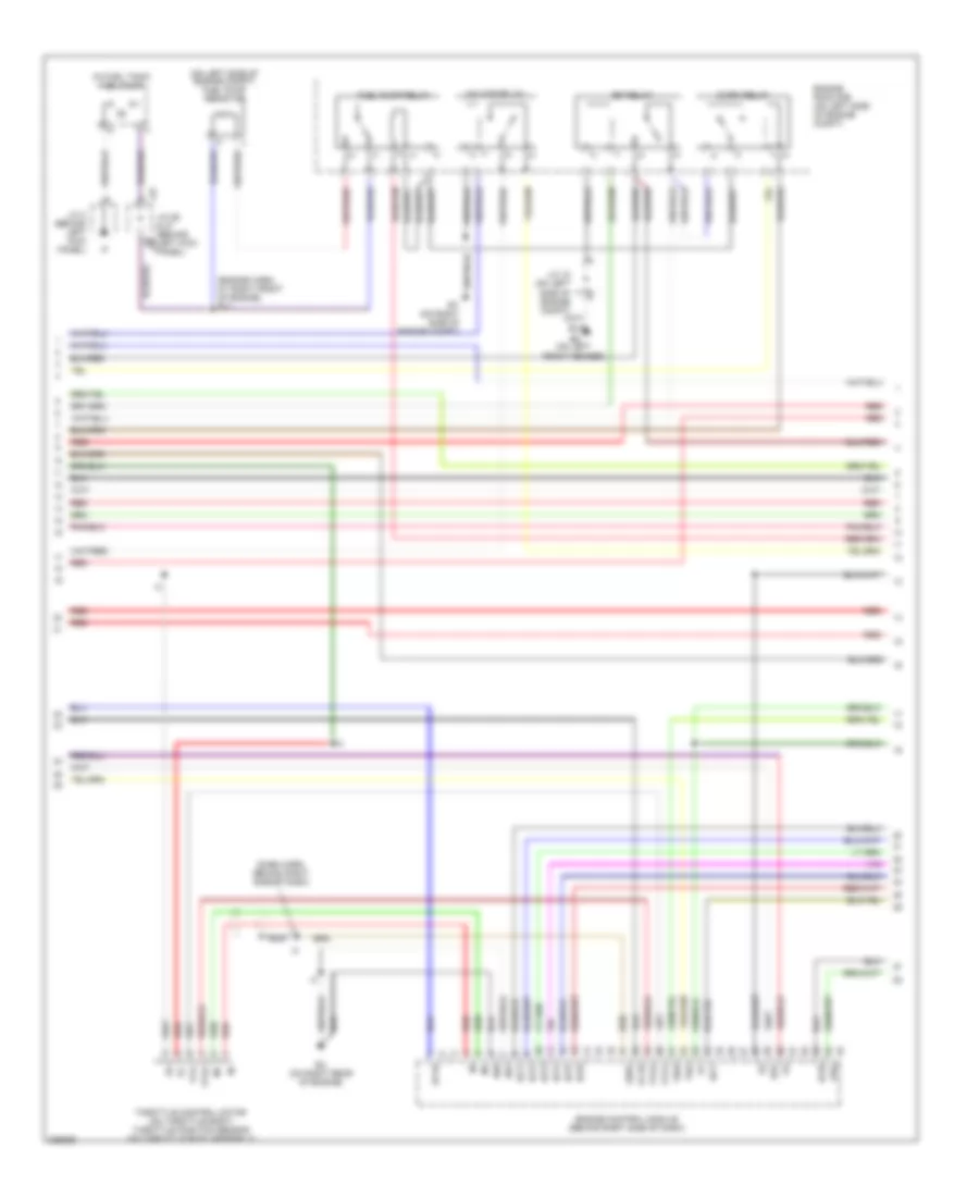
4.7L, Engine Performance Wiring Diagram, Access/Standard Cab (3 of 7) for Toyota Tundra SR5 2006
List of elements for 4.7L, Engine Performance Wiring Diagram, Access/Standard Cab (3 of 7) for Toyota Tundra SR5 2006:
- (dash harn, behind right side of dash)
- (engine harn, at right front of engine) e11
- (in fuel tank) fuel pump
- (on left side of engine compt) fuel pump resistor
- A/f htr relay
- Acis
- Aip
- Air pressure sensor (on top left of engine)
- Aiv1
- Aiv2
- C/opn relay
- E01
- E02
- E2g
- Ea (on left front fender)
- Ec (on rear of engine)
- Efi relay
- Engine control module (behind right side of dash)
- Engine room r/b (on left side of engine compt)
- Et (right front fender)
- Fuel pump relay
- Ge01
- Ht1b
- Igf1
- Igf2
- Igt1
- Igt2
- Igt3
- Igt4
- Igt5
- Igt6
- Igt7
- Igt8
- J/c 18 (on left side of engine compt)
- J/c 26 & 27 (behind left kick panel)
- J/c 3 (behind left kick panel)
- J26
- J27
- Nca
- Ox1b
- Pnk
- Prg
- Red
- Tha
- Throttle control motor (on throttle body) throttle position sensor (on throttle body assembly)
- Thw
- Vta
- Vta1
- Vta2
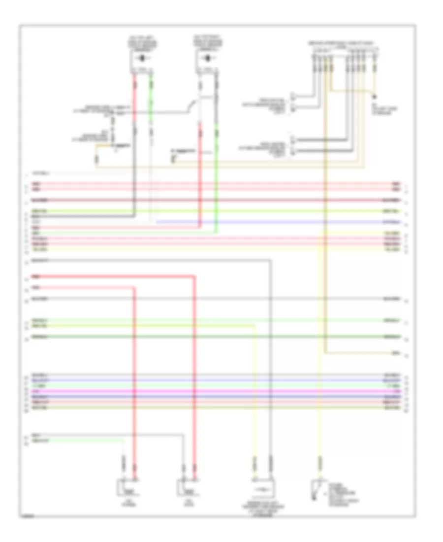
4.7L, Engine Performance Wiring Diagram, Access/Standard Cab (4 of 7) for Toyota Tundra SR5 2006
List of elements for 4.7L, Engine Performance Wiring Diagram, Access/Standard Cab (4 of 7) for Toyota Tundra SR5 2006:
- (behind upper right side of dash) j/c 64
- (on left side
- (on right side
- A32
- A33
- Air injection control driver (left side of engine compt)
- Air pump (on top left of engine)
- Air switching valve (on top left of engine)
- Airp fuse 60a
- Batt
- E13
- Engine coolant temperature sensor (on right front of engine)
- Engine room r/b (on left side of engine compt)
- Ew (top left side of engine)
- Ex (on right rear of engine)
- From air fuel ratio sensor shields (diagram 2 of 7)
- From heated oxygen sensor shields (diagram 2 of 7)
- Hot at all times
- Nca
- Of engine) knock sensor (bank 1)
- Of engine) knock sensor (bank 2)
- Pnk
- Red
- Sip
- Siv
- Vsv (acis) (top left of engine)
- Vsv (air switching valve bank 1) (top center of engine)
- Vsv (air switching valve bank 2) (left rear of engine)
- Vsv (purge)
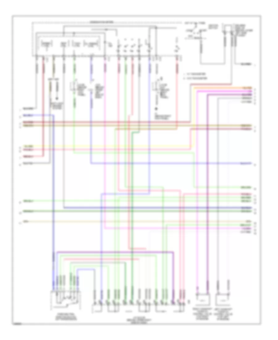
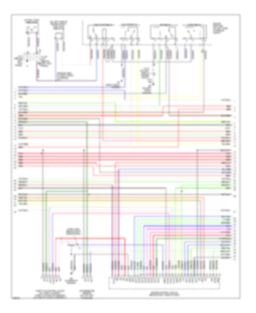
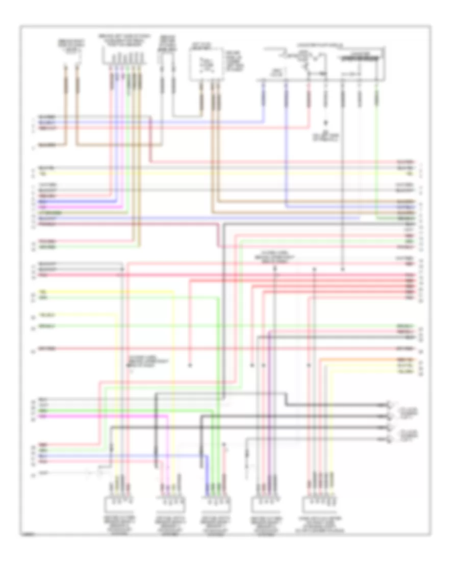
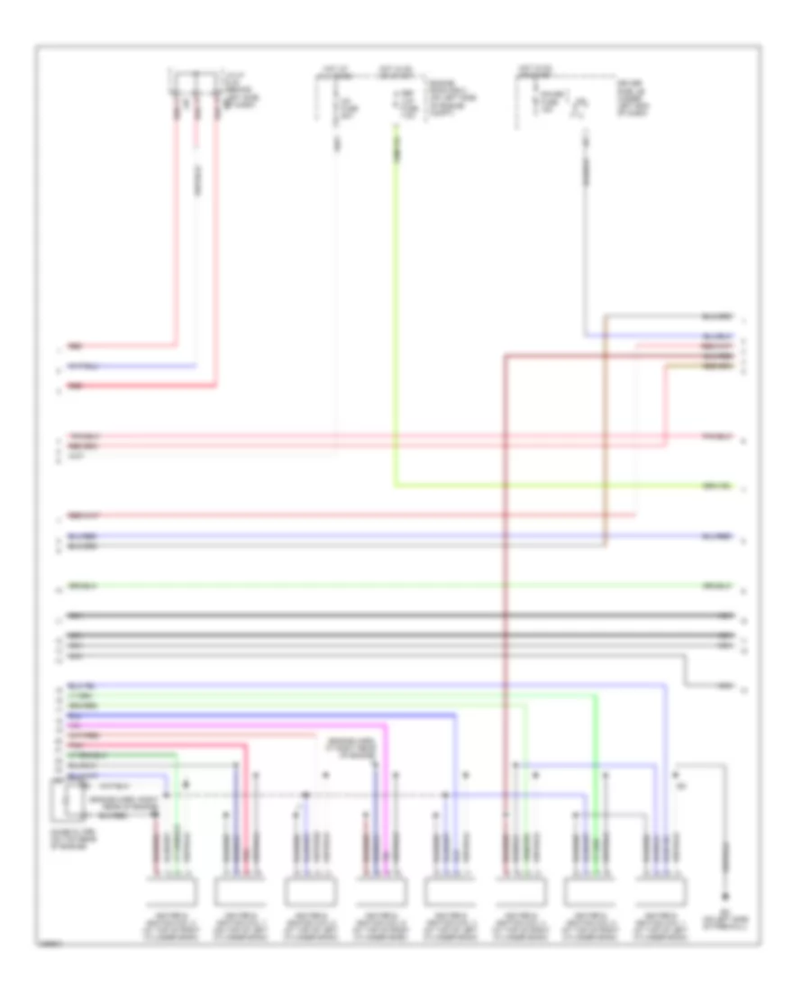
4.7L, Engine Performance Wiring Diagram, Access/Standard Cab (5 of 7) for Toyota Tundra SR5 2006
List of elements for 4.7L, Engine Performance Wiring Diagram, Access/Standard Cab (5 of 7) for Toyota Tundra SR5 2006:
- (behind upper left side of dash, near instrument cluster) diode (a/t)
- (dash harn, behind right side of dash) i3
- (engine harn, at rear of engine) e5
- A red
- A/f htr fuse 20a
- Acc fuse 15a
- Driver's side j/b (behind lower left side of dash)
- Ec (on rear of engine)
- Efi 1 fuse 20a
- Efi 2 fuse 10a
- Engine room r/b (on left side of engine compt)
- Etcs fuse 10a
- G11
- Gauge fuse 10a
- Hot at all times
- Hot in on or acc
- Hot in on or start
- Igniter & ignition coil 1 (at top of left cylinder bank)
- Igniter & ignition coil 2 (at top of right cylinder bank)
- Igniter & ignition coil 3 (at top of left cylinder bank)
- Igniter & ignition coil 4 (at top of right cylinder bank)
- Igniter & ignition coil 5 (at top of left cylinder bank)
- Igniter & ignition coil 6 (at top of right cylinder bank)
- Igniter & ignition coil 7 (at top of left cylinder bank)
- Igniter & ignition coil 8 (at top of right cylinder bank)
- J/c 8 (behind upper left side of dash)
- J/c 9 (behind upper left side of dash)
- J26
- J26 j/c 26 & 27 (behind left kick panel)
- J27
- Nca
- Noise filter (on top rear of engine)
- Pnk
- Red
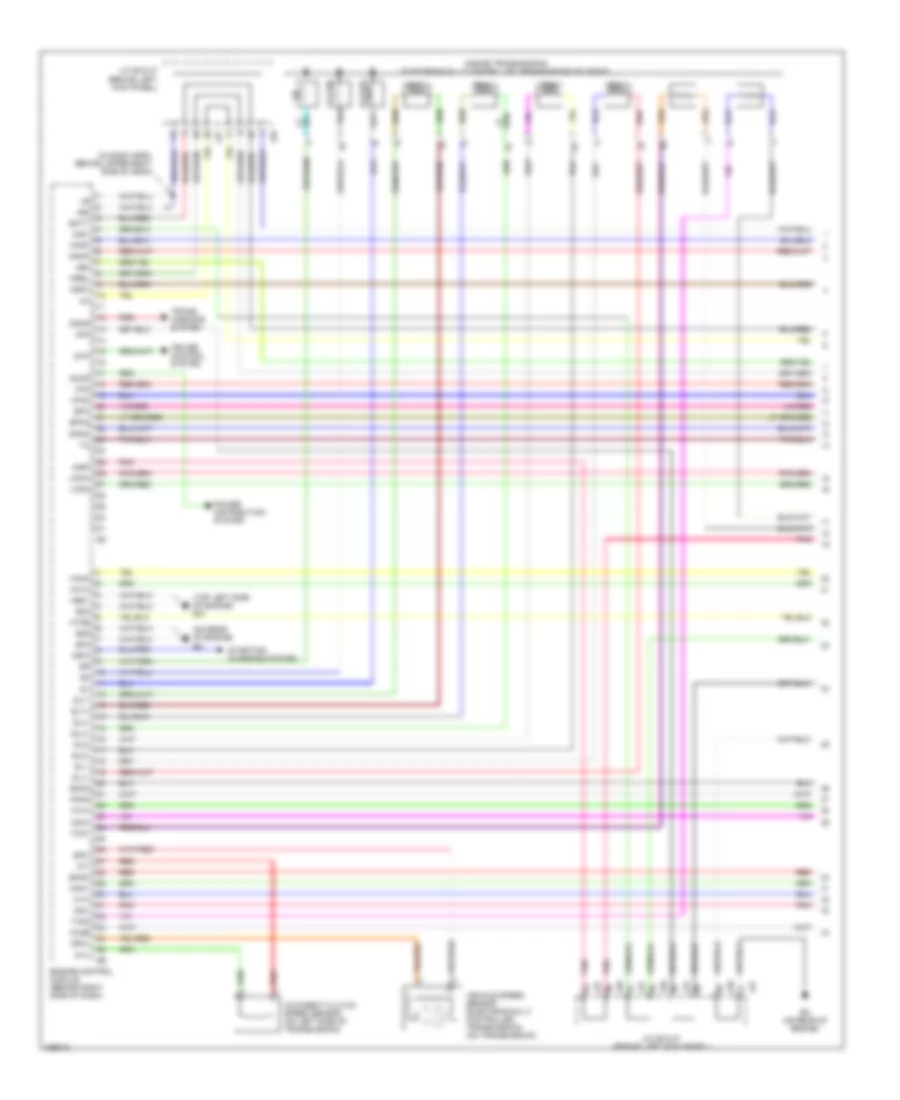
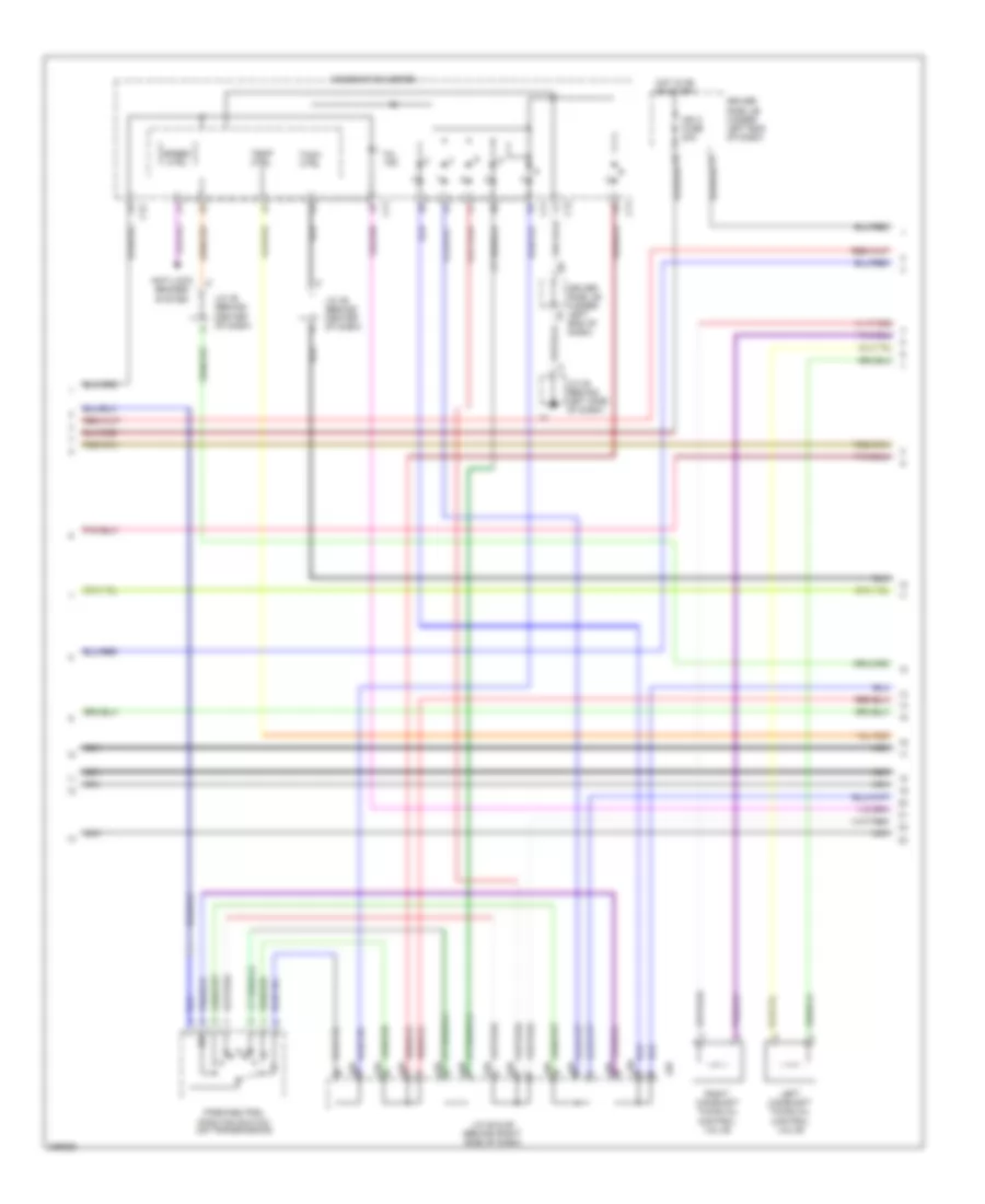
4.7L, Engine Performance Wiring Diagram, Access/Standard Cab (6 of 7) for Toyota Tundra SR5 2006
List of elements for 4.7L, Engine Performance Wiring Diagram, Access/Standard Cab (6 of 7) for Toyota Tundra SR5 2006:
- A j28
- Acc
- Anti-lock brakes system
- B j28
- C j28
- C11
- C12
- Combination meter combination meter
- D j28
- Driver's side j/b (behind lower left side of dash)
- F j28
- G j28
- Hot at all times
- Ignition switch
- Ih (behind right kick panel)
- J/c 28 & 29 (behind upper right side of dash)
- J/c 5 (behind upper left side of dash)
- J/c 66 (behind right kick panel)
- J29
- J66 j/c 66 & 67 (behind right kick panel) j67
- Left camshaft timing oil control valve (on top left of engine)
- Lock
- Mil ind
- Nca
- Park/neutral position switch (on transmission)
- Right camshaft timing oil control valve (on top right of engine)
- Run
- Speed ctrl
- Start
- Tach ctrl
- Temp ctrl
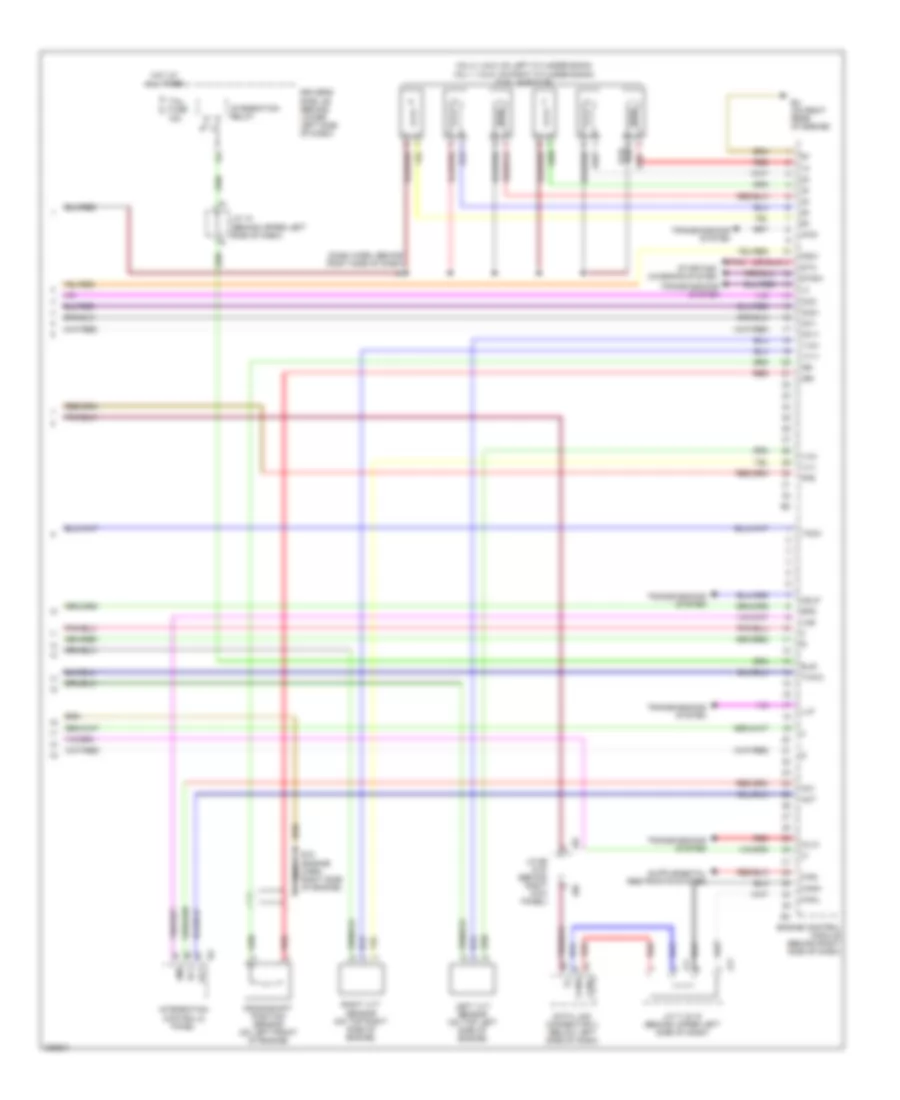
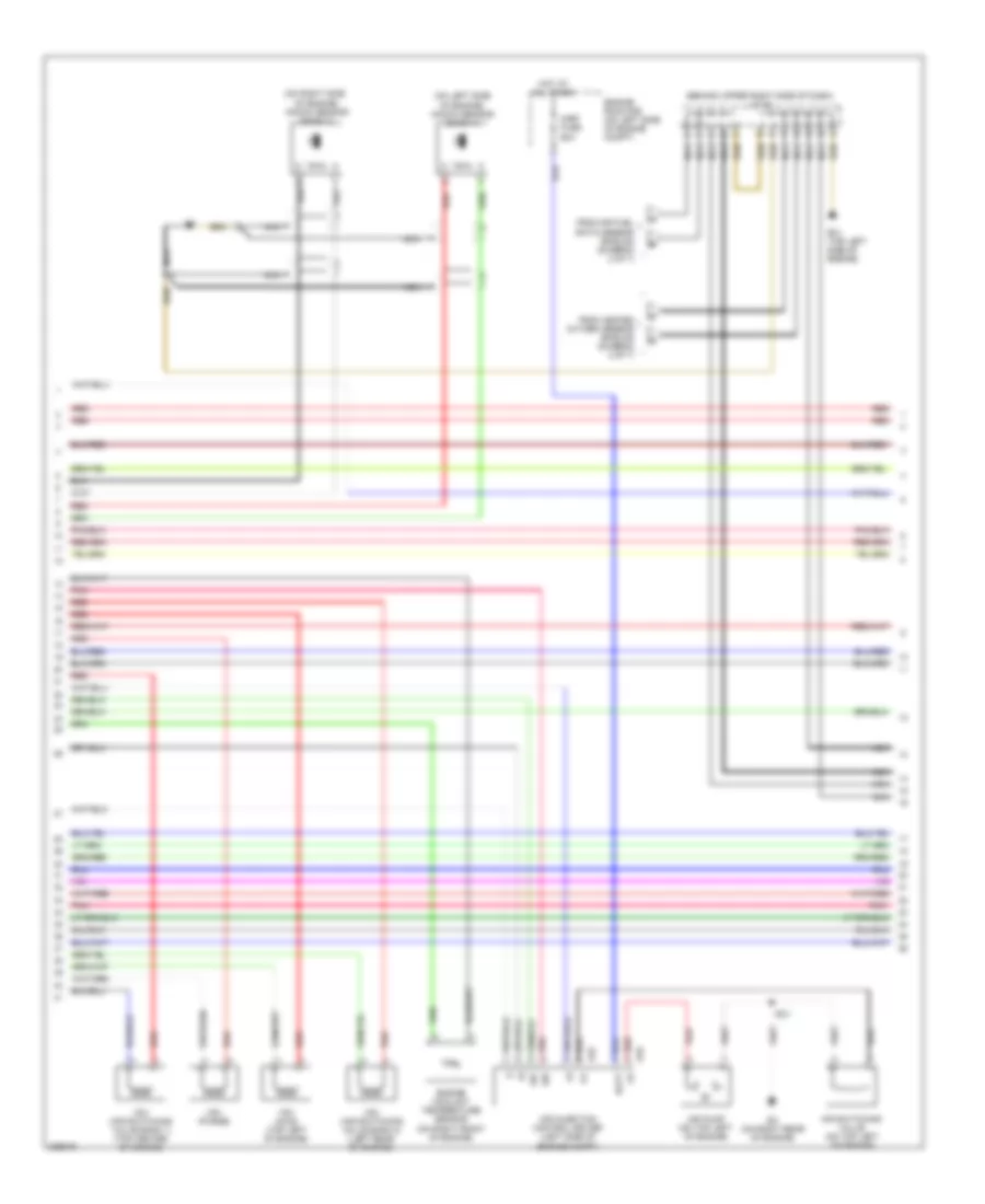
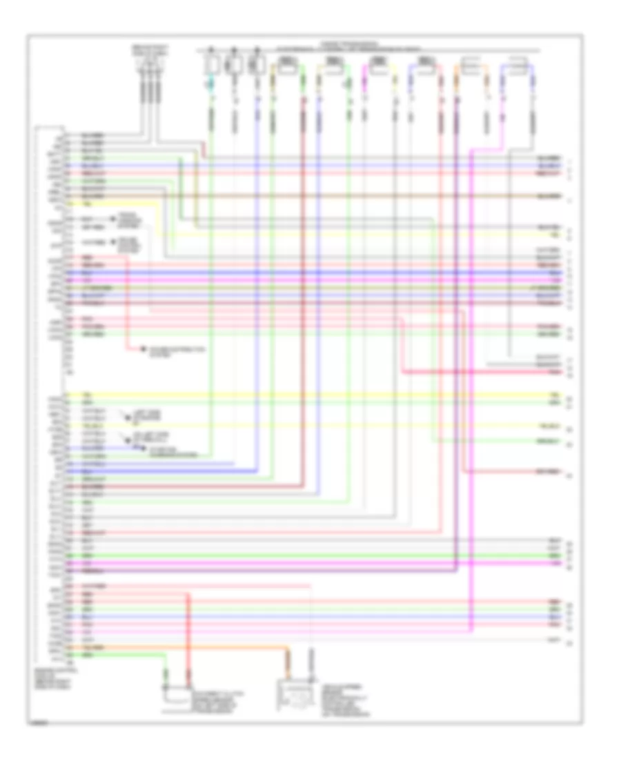
4.7L, Engine Performance Wiring Diagram, Access/Standard Cab (7 of 7) for Toyota Tundra SR5 2006
List of elements for 4.7L, Engine Performance Wiring Diagram, Access/Standard Cab (7 of 7) for Toyota Tundra SR5 2006:
- (behind right kick panel) j/c 13
- (engine harn, at rear of engine) e5
- (inj 1, 3, 5 & 7: at top of left cylinder bank) (inj 2, 4, 6 & 8: at top of right cylinder bank) fuel injectors
- 4wd
- Ac1
- Act
- Camshaft position sensor (at left front of engine)
- Canh
- Canl
- Crankshaft position sensor (at left front of engine)
- Data link connector 3 (below left side of dash)
- Driver's side j/b (behind lower left side of dash)
- Ec (on rear of engine)
- Elsi
- Engine control module (behind right side of dash)
- Ev1+
- Ev1-
- F/ps
- Frp
- G2+
- G2-
- Hot at all times
- I24
- Integration control & panel
- Integration relay
- J/c 10 (behind upper left side of dash)
- J/c 66 & 67 (behind right kick panel)
- J/c 71 & 72 (behind upper left side of dash)
- J66
- J67
- J71
- J72
- Left vvt sensor (on top left side of engine)
- Llp
- Lms
- Nca
- Ne+
- Ne-
- Oc1+
- Oc1-
- Oc2+
- Oc2-
- Odlp
- Oilw
- Pnk
- Red
- Right vvt sensor (on top right side of engine)
- Spd
- Sta
- Starting/ charging system
- Stsw
- Tach
- Tail fuse 15a
- Thwo
- Transmissions system
- Vv2+
- Vv2-
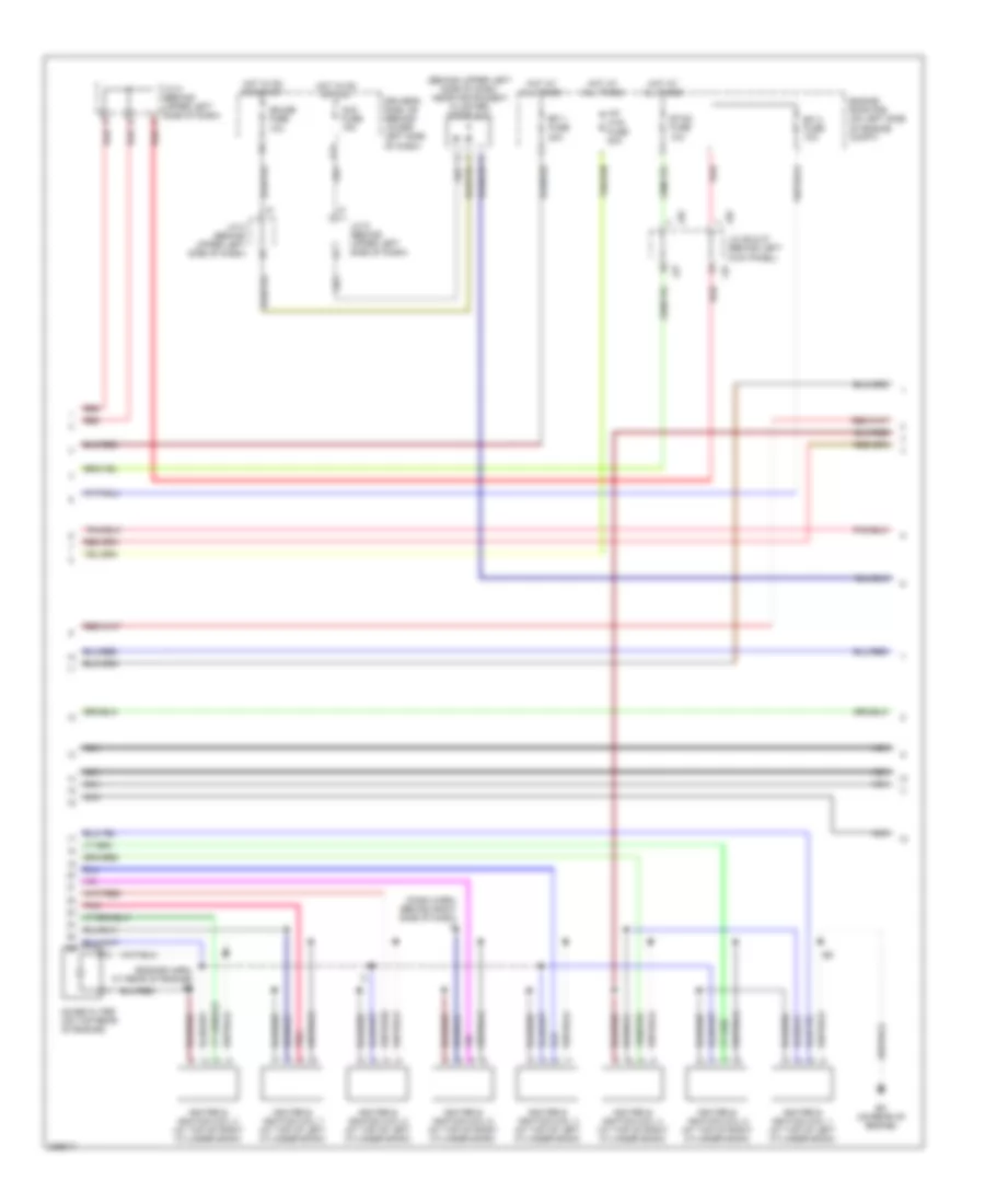
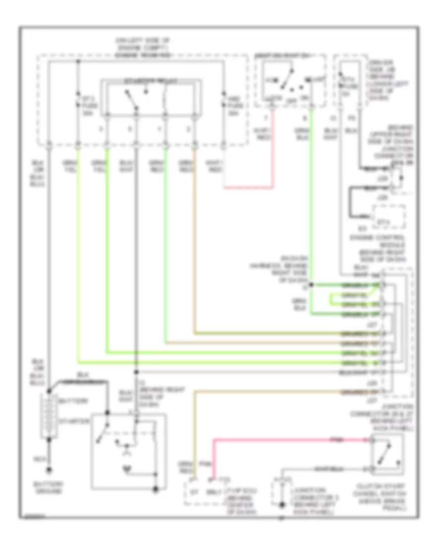
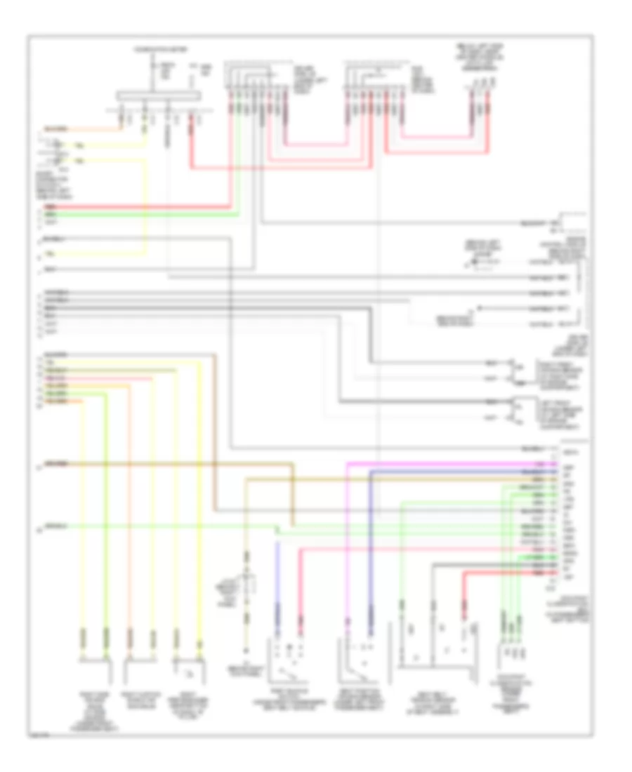
4.7L, Engine Performance Wiring Diagram, Double Cab (1 of 7) for Toyota Tundra SR5 2006
List of elements for 4.7L, Engine Performance Wiring Diagram, Double Cab (1 of 7) for Toyota Tundra SR5 2006:
- (behind right side of dash) j/c 75
- (inside transmission) electronically controlled transmission solenoid
- (left side of engine) ey
- (on left side of firewall) ec
- +b2
- +bm
- A1a+
- A1a-
- A2a+
- A2a-
- Accr
- Aidi
- Airp
- Airv
- Batt
- Cruise control system
- E03
- E04
- E05
- Ekn2
- Eknk
- Engine control module (behind right side of dash)
- Epa
- Epa2
- Ha1a
- Ha2a
- Ht2b
- Igsw
- Knk1
- Knk2
- Me01
- Mpmp
- Mrel
- Nsw
- Nt+
- Nt-
- O/d direct clutch speed sensor (on left side of transmission)
- Odms
- Ox2b
- Pnk
- Power distribution system
- Ppmp
- Red
- Sl1
- Sl1+
- Sl1-
- Sl2
- Sl2+
- Sl2-
- Slt
- Slt+
- Slt-
- Slu
- Slu+
- Slu-
- Sp2+
- Sp2-
- Starting/ charging system
- Stp
- Th02
- Tho1
- Trans- missions system
- Vcp2
- Vcpa
- Vehicle speed sensor (electronically controlled transmission) (on transmission)
- Vpa
- Vpa2
- Vpmp
4.7L, Engine Performance Wiring Diagram, Double Cab (2 of 7) for Toyota Tundra SR5 2006
List of elements for 4.7L, Engine Performance Wiring Diagram, Double Cab (2 of 7) for Toyota Tundra SR5 2006:
- (behind center of dash) sub j/b 3
- (behind left side of dash) accelerator pedal position sensor
- (behind right side of dash) j/c 75
- (in dash harn, behind upper right end of dash)
- Af+
- Af-
- Air fuel ratio sensor (bank 1 sensor 1) (on exhaust system)
- Air fuel ratio sensor (bank 2 sensor 1) (on exhaust system)
- Canister pressure sensor
- Canister pump module
- Driver side j/b (under left end of dash)
- E17
- E2g
- Ec (on left side of firewall)
- Epa
- Epa2
- H11
- Heated oxygen sensor (bank 1 sensor 2) (on exhaust system)
- Heated oxygen sensor (bank 2 sensor 2) (on exhaust system)
- Hot in on or start
- Ign 1 fuse 10a
- Leak detection pump
- Mass air flow meter (on right side of engine compt, on air cleaner housing)
- Nca
- Nca a
- Nca b
- Nca c
- Nca d
- Pnk
- Red
- Tha
- To j/c 64 (diagram 4 of 7)
- Vcp2
- Vcpa
- Vent valve
- Vpa
- Vpa2
4.7L, Engine Performance Wiring Diagram, Double Cab (3 of 7) for Toyota Tundra SR5 2006
List of elements for 4.7L, Engine Performance Wiring Diagram, Double Cab (3 of 7) for Toyota Tundra SR5 2006:
- (dash harn, behind upper right end of dash)
- (in fuel tank) fuel pump
- (on left side of engine compt) fuel pump resistor
- Acis
- Aip
- Air pressure sensor
- Aiv1
- Aiv2
- Bq (below left front seat)
- C/opn relay
- E01
- E02
- E2g
- Ea (on left front fender)
- Ec (on left side of firewall)
- Efi 1 fuse 20a
- Efi 2 fuse 10a
- Efi relay
- Engine control module (behind right side of dash)
- Engine room j/b (on left side of engine compt)
- Etcs fuse 10a
- Fuel pump relay
- Ge01
- Hot at all times
- Ht1b
- Igf1
- Igf2
- Igt1
- Igt2
- Igt3
- Igt4
- Igt5
- Igt6
- Igt7
- Igt8
- J/c 34 (on left side of engine compartment)
- Nca
- Ox1b
- Pnk
- Prg
- Red
- Tha
- Throttle control motor (on throttle body) throttle position sensor (on throttle body assembly)
- Thw
- Vta1
- Vta2
4.7L, Engine Performance Wiring Diagram, Double Cab (4 of 7) for Toyota Tundra SR5 2006
List of elements for 4.7L, Engine Performance Wiring Diagram, Double Cab (4 of 7) for Toyota Tundra SR5 2006:
- (behind right side of dash) j/c 64
- (on left side
- (on right side
- A/f relay
- A32
- A33
- Air injection control driver (left side of engine compt)
- Air pump (on top left of engine)
- Air pump fuse 50a
- Air switching valve (top left on engine)
- Batt
- Ea (on left front fender)
- Ec (on left side of firewall)
- Engine coolant temperature sensor (on right front of engine)
- Engine room r/b 2 (on left side of engine compt)
- Ey (left side of engine)
- Ez (on right rear of engine)
- From air fuel ratio sensor shields (diagram 2 of 7)
- From heated oxygen sensor shields (diagram 2 of 7)
- Fusible link block (on left side of engine compt)
- Hot at all times
- J/c 34 (on left side of engine compartment)
- Nca
- Of engine) knock sensor (bank 1)
- Of engine) knock sensor (bank 2)
- Pnk
- Red
- Sip
- Siv
- Vsv (acis)
- Vsv (air switching valve bank 1) (top center of engine)
- Vsv (air switching valve bank 2) (left rear of engine)
- Vsv (purge)
4.7L, Engine Performance Wiring Diagram, Double Cab (5 of 7) for Toyota Tundra SR5 2006
List of elements for 4.7L, Engine Performance Wiring Diagram, Double Cab (5 of 7) for Toyota Tundra SR5 2006:
- (engine harn, at right rear of engine) i1
- (engine harn, right rear of engine) e2
- A red
- A/f fuse 20a
- C red
- Def i/up fuse 7.5a
- Driver side j/b (under left end of dash)
- Ec (on left side of firewall)
- Engine room r/b 2 (on left side of engine compt)
- Gauge fuse 15a
- Hot at all times
- Hot in on or start
- Igniter & ignition coil 1 (at top of left cylinder bank)
- Igniter & ignition coil 2 (at top of right cylinder bank)
- Igniter & ignition coil 3 (at top of left cylinder bank)
- Igniter & ignition coil 4 (at top of right cylinder bank)
- Igniter & ignition coil 5 (at top of left cylinder bank)
- Igniter & ignition coil 6 (at top of right cylinder bank)
- Igniter & ignition coil 7 (on top of left cylinder bank)
- Igniter & ignition coil 8 (at top of right cylinder bank)
- Ipo
- J/c 47 & 48 (behind left side of dash) j47
- J48
- Nca
- Noise filter (on top rear of engine)
- Pnk
- Red
4.7L, Engine Performance Wiring Diagram, Double Cab (6 of 7) for Toyota Tundra SR5 2006
List of elements for 4.7L, Engine Performance Wiring Diagram, Double Cab (6 of 7) for Toyota Tundra SR5 2006:
- A j28
- Anti-lock brakes system
- B j28
- C j28
- C11
- C12
- Combination meter
- D j28
- Driver side j/b (under left end of dash)
- F j28
- G j28
- Hot in on or start
- Ign 2 fuse 20a
- J/c 28 & 29 (behind right side of dash)
- J/c 45 (behind left side of dash)
- J/c 49 (behind center of dash)
- J29
- Left camshaft timing oil control valve
- Mil ind
- Nca
- Park/neutral position switch (on transmission)
- Right camshaft timing oil control valve
- Speed ctrl
- Tach ctrl
- Temp ctrl
4.7L, Engine Performance Wiring Diagram, Double Cab (7 of 7) for Toyota Tundra SR5 2006
List of elements for 4.7L, Engine Performance Wiring Diagram, Double Cab (7 of 7) for Toyota Tundra SR5 2006:
- (behind center of dash) sub j/b 3
- (engine harn, right rear of engine) e2
- (inj 1, 3, 5 & 7: at top of left cylinder bank) (inj 2, 4, 6 & 8: at top of right cylinder bank) fuel injectors
- 4wd
- Ac1
- Act
- Camshaft position sensor (at left front of engine)
- Canh
- Canl
- Crankshaft position sensor (at left front of engine)
- Data link connector 3 (below left side of dash)
- Driver side j/b (under left end of dash)
- E18
- Ec (on left side of firewall)
- Els
- Els2
- Engine control module (behind right side of dash)
- Engine room r/b 2 (on left side of engine compartment)
- F/ps
- Fpr
- G2+
- G2-
- Hot at all times
- Hot in start
- I24
- Integration control & panel
- J/c 45 (behind left side of dash)
- J/c 49 (behind center of dash)
- J/c 76 & 77 (behind right side of dash)
- J76
- J77
- Left vvt sensor (on top left side of engine)
- Llp
- Lms
- Nca
- Ne+
- Ne-
- Oc1+
- Oc1-
- Oc2+
- Oc2-
- Odlp
- Oilw
- Pnk
- Red
- Right vvt sensor (on top right side of engine)
- Spd
- Sta
- Sta fuse 7.5a
- Starting/ charging system
- Stsw
- Sub j/b 3 (behind center of dash)
- Tach
- Tail fuse 15a
- Thwo
- Transmissions system
- Vv1+
- Vv1-
- Vv2+
- Vv2-
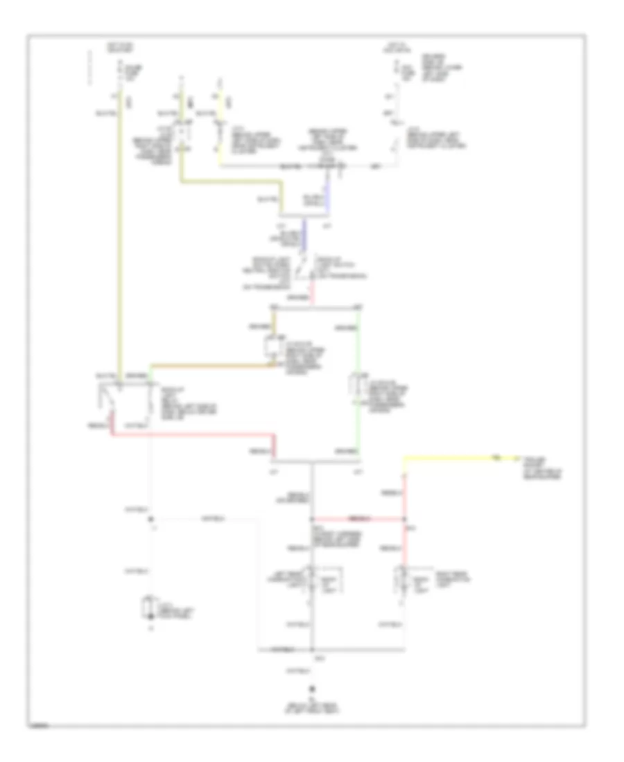
EXTERIOR LIGHTS
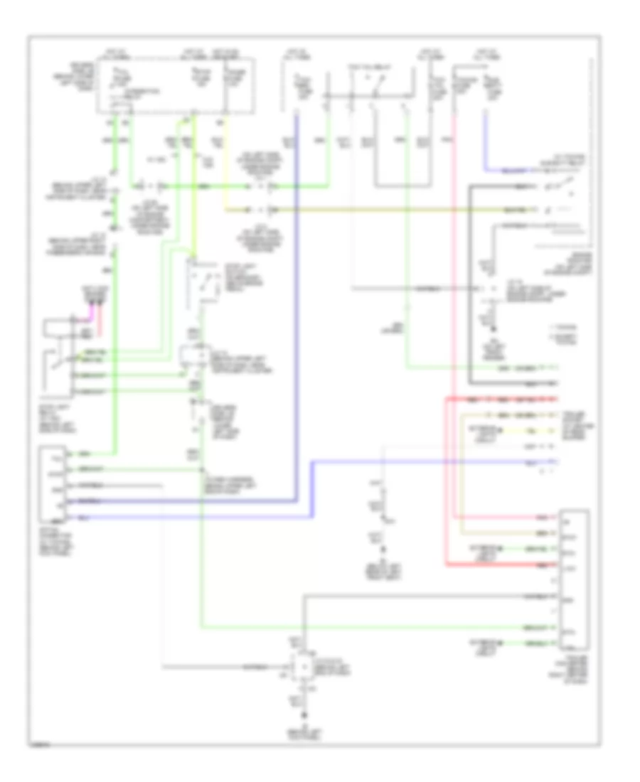
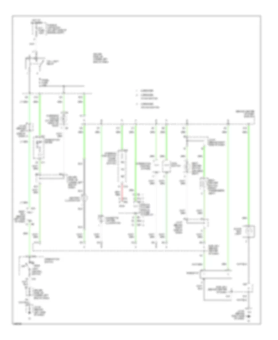
Back-up Lamps Wiring Diagram, Access/Standard Cab for Toyota Tundra SR5 2006
List of elements for Back-up Lamps Wiring Diagram, Access/Standard Cab for Toyota Tundra SR5 2006:
- (a/t)
- (behind upper left side of dash, near instrument cluster) (a/t) diode
- (m/t)
- A/t
- Acc fuse 15a
- B10
- Back- up light
- Back-up light relay (behind left side of dash, below driver side j/b)
- Back-up light switch (m/t) (on transmission)
- Back-up light switch (park/ neutral position switch) (a/t) (on transmission)
- Bl (below left rear of left front seat)
- D j29
- Driver's side j/b (behind lower left side of dash)
- F j29
- G11
- Gauge fuse 10a
- H j28
- Hot in acc or on
- Hot in on or start
- J/c 28 & 29 (behind upper right side of dash, near passenger's air bag)
- J/c 28 & 29 (behind upper right side of dash, near passenger's airbag)
- J/c 3 (behind left kick panel)
- J/c 8 (behind upper left side of dash, near instrument cluster)
- J/c 9 (behind upper left side of dash, near instrument cluster)
- J28
- J28 b
- Left rear combination light
- M/t
- Right rear combination light
- Trailer socket (at center of rear bumper)
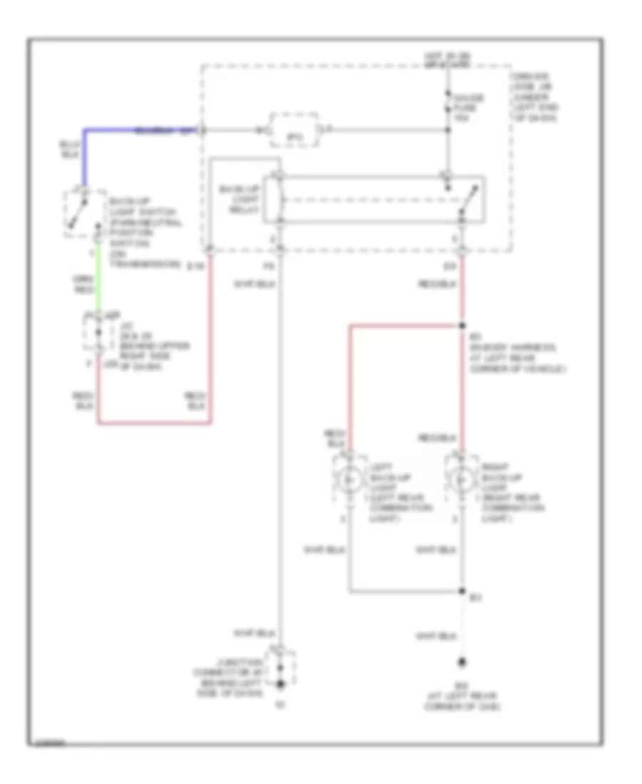
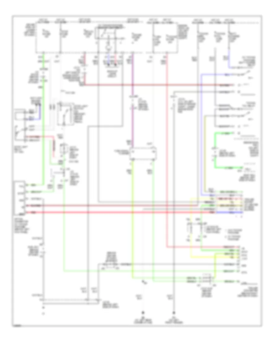
Back-up Lamps Wiring Diagram, Double Cab for Toyota Tundra SR5 2006
List of elements for Back-up Lamps Wiring Diagram, Double Cab for Toyota Tundra SR5 2006:
- B3 (in body harness, at left rear corner of vehicle)
- Back-up light relay
- Back-up light switch (park/neutral position switch) (on transmission)
- Bs (at left rear corner of cab)
- Driver side j/b (under left end of dash)
- E19
- Gauge fuse 15a
- Hot in on or start
- Ipo
- J/c 28 & 29 (behind upper right side j29 of dash)
- J28
- Junction connector 45 (behind left side of dash)
- Left back-up light (left rear combination light)
- Right back-up light (right rear combination light)
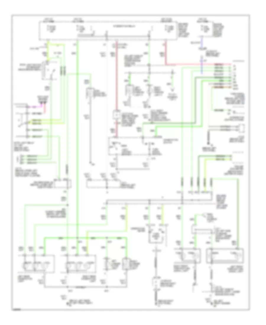
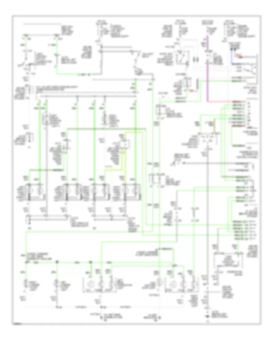
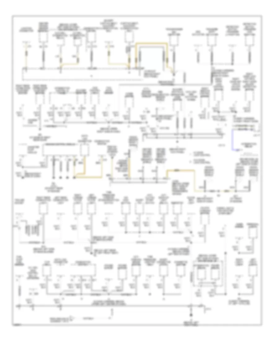
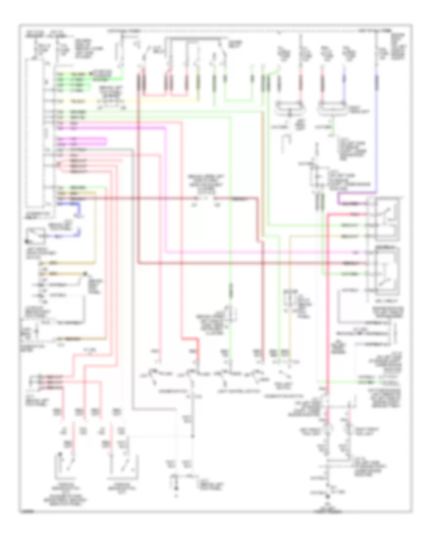
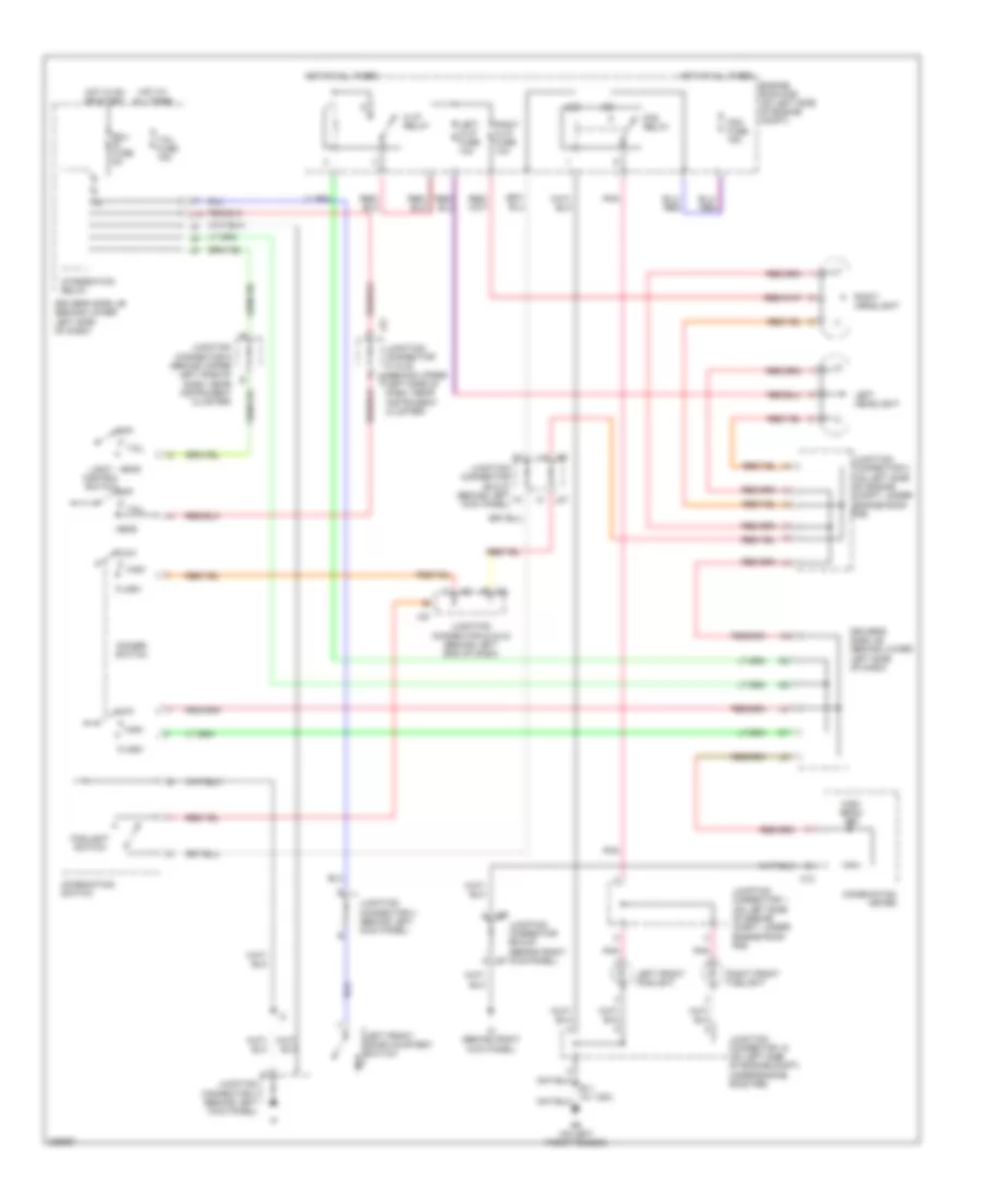
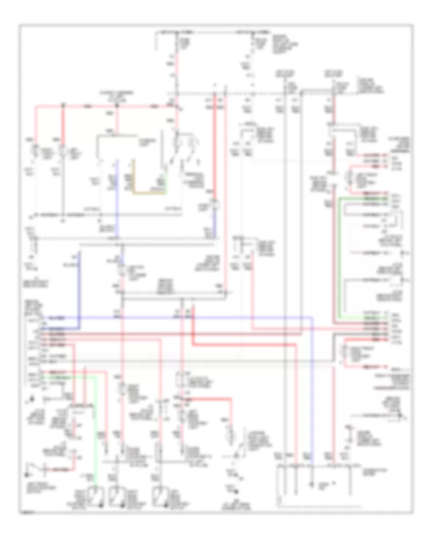
Exterior Lamps Wiring Diagram, Access/Standard Cab for Toyota Tundra SR5 2006
List of elements for Exterior Lamps Wiring Diagram, Access/Standard Cab for Toyota Tundra SR5 2006:
- (4.7l: right front fender) (except 4.7l: on right side of engine compt) et
- (behind left kick panel)
- (behind right kick panel) ih
- (below left rear of left front seat) bl
- (on left front fender) ea
- (on left side of engine compt, under engine room r/b) j/c 63
- (w/o drl)
- Anti-lock brakes system
- B10
- B10 (in body harness, behind left side of rear bumper)
- C j21
- C11
- C12
- C15
- Combination meter
- Combination switch
- D10
- D11
- Driver's side j/b (behind lower left side of dash)
- E11
- Ehw
- Engine room r/b (on left side of engine compt)
- From j/c 63 (diagram 1 of 1)
- Gnd
- H12
- H13
- Haz fuse 15a
- Head
- High mounted stoplight
- Hot at all times
- Hot in on or start
- I24
- Integration control & panel
- Integration relay
- J/c 1 (on left side of engine compt, under engine room r/b)
- J/c 10 (behind upper left side of dash, near instrument cluster)
- J/c 18 (on left side of engine compt, under engine room r/b)
- J/c 21 & 22 (behind upper left side of dash, near instrument cluster)
- J/c 23 (behind left end of dash)
- J/c 26 & 27 (behind left kick panel)
- J/c 3 (behind left kick panel)
- J/c 66 & 67 (behind right kick panel)
- J22 a
- J26
- J27
- J66
- J67
- L13
- Left front parking light 3
- Left front parking/turn signal light
- Left license plate light
- Left rear combination light
- Light control switch
- N4 (w/ drl)
- Off
- Park
- Right front parking light 3
- Right front parking/turn signal light
- Right license plate light
- Right rear combination light
- Stop
- Stop fuse 15a
- Stop light relay (w/ vsc) (behind left side of dash)
- Stop light switch (on bracket, above brake pedal)
- Tail
- Tail fuse 15a
- To j/c 1 (diagram 1 of 1)
- Trailer converter (behind right center of dash)
- Turn
- Turn fuse 5a
- Turn signal flasher (behind left side of dash, below driver side j/b)
- Turn signal ind
- Turn signal switch
- W/ vsc
- W/o vsc
Exterior Lamps Wiring Diagram, Double Cab for Toyota Tundra SR5 2006
List of elements for Exterior Lamps Wiring Diagram, Double Cab for Toyota Tundra SR5 2006:
- (4.7l: on left side of engine compt, under engine room r/b) j/c 74
- (at left rear corner of cab) bs
- (behind left side of dash)
- (in left rear door) br
- Alt fuse 140a
- Anti-lock brakes system
- B j47
- B10
- B2 (in body harness, in left rear door)
- Body ecu (behind left side of dash)
- C11
- C12
- C15
- Combination meter
- D j47
- Driver side j/b (under left end of dash)
- E j38
- E11
- Engine room j/b (on left side of engine compt)
- F j39
- Fusible link block (on left side of engine compt)
- Gauge fuse 15a
- Haz
- Hazard switch (integration control & panel)
- Head
- High mounted stop light
- Hot at all times
- Hot in on or start
- J/c 30 (on right front of engine compt)
- J/c 31 (on left side of engine b compt, under engine room r/b)
- J/c 31 (on left side of engine compt, under engine room r/b)
- J/c 35 (on left front of engine compt)
- J/c 38 & 39 (behind left kick panel)
- J/c 45
- J/c 45 (behind left side of dash)
- J/c 46 (behind left side of dash)
- J/c 47 & 48 (behind left side of dash)
- J/c 51 & 52 (behind center of dash)
- J/c 51, 52 & 53 (behind center of dash)
- J38 f
- J39 m
- J47
- J48
- J51
- J52
- J53
- L j39
- Left front park/ turn signal light
- Left front park/ turn signal light 2
- Left front parking signal light 3
- Left license plate light
- Left rear combination light
- Light control switch (combination switch)
- M j38
- Off
- Park
- Red
- Right front park/ turn signal light
- Right front park/ turn signal light 2
- Right front parking signal light 3
- Right license plate light
- Right rear combin- ation light
- Stop
- Stop fuse 15a
- Stop light relay (w/ vsc)
- Stop light switch (on bracket, above brake pedal)
- Tail
- Tail fuse 15a
- Taillight relay
- Trly
- Turn
- Turn signal flasher
- Turn signal indicator lights
- Turn signal switch (combination switch)
- Turn- haz fuse 20a
- W/o vsc
Trailer Tow Wiring Diagram, Access/Standard Cab for Toyota Tundra SR5 2006
List of elements for Trailer Tow Wiring Diagram, Access/Standard Cab for Toyota Tundra SR5 2006:
- (on left side of engine compt, under engine room r/b) j/c 1
- (w/ towing) sub batt relay
- A j24
- Anti-lock brakes system
- B10
- Bl (below left rear of left front seat)
- Brk
- Driver's side j/b (behind lower left side of dash)
- Ea (on left front fender)
- Engine room r/b (on left side of engine compt)
- Except
- Exterior lights circuit
- Gauge fuse 10a
- Gnd
- Hot at all times
- Hot in on or start
- I1 (in dash harness, behind upper left end of dash)
- Ie (behind left kick panel)
- Integration relay
- J/c 10 (behind upper left side of dash, near instrument cluster)
- J/c 10 (behind upper left side of dash, near instrument cluster) e
- J/c 12 (behind upper right side of dash, near passenger's air bag) e
- J/c 18 (on left side of engine compt, under engine room r/b)
- J/c 2 (on left side of engine compt, under engine room r/b)
- J/c 23 & 24 (behind left end of dash)
- J/c 63 (on left side of engine compartment, under engine room r/b)
- J23
- J24
- Ltin
- Ltot
- Option connector (w/ towing) (behind left kick panel)
- Pnk
- Red
- Rtin
- Rtot
- Stin
- Stop
- Stop fuse 15a
- Stop light relay (w/ vsc) (behind left side of dash)
- Stop light switch (on bracket, above brake pedal)
- Sub batt fuse 30a
- Tail
- Tail fuse 15a
- Tow brk fuse 30a
- Tow tail fuse 30a
- Tow tail relay
- Towing
- Towing fuse 30a
- Trailer converter (behind right center of dash)
- Trailer socket (at center of rear bumper)
- W/ vsc
- W/o vsc
Trailer Tow Wiring Diagram, Double Cab for Toyota Tundra SR5 2006
List of elements for Trailer Tow Wiring Diagram, Double Cab for Toyota Tundra SR5 2006:
- (at center of rear bumper)
- (behind center of dash) j/c 52 & 53
- (w/ towing package) back-up light relay
- (w/ towing package) batt charge relay
- Anti-lock brakes system
- B10
- Back-up lamps circuit
- Batt charge fuse 30a
- Body ecu (behind left side of dash)
- Brk
- Bs (at left rear corner of cab)
- Driver side j/b (under left end of dash)
- E18
- E19
- Ea (on left front fender)
- Ecu-ig fuse 10a
- Engine room j/b (on left side of engine compt)
- Engine room r/b 3 (on left side of engine compt)
- Gauge fuse 15a
- Gnd
- Hot at all times
- Hot in on or start
- Ipo
- J/c 31 (on left side of engine compt, under engine room r/b)
- J/c 34 (4.7l: on left side of engine compt, under engine room r/b)
- J/c 38 & 39 (behind left kick panel)
- J/c 45 (behind left side of dash)
- J/c 46 (behind left side of dash)
- J/c 47 & 48 (behind left side of dash)
- J/c 47 (behind left side of dash)
- J/c 49 & 50 (behind center of dash)
- J/c 51 & 52 (behind center of dash)
- J/c 51 & 53 (behind center of dash)
- J38
- J39
- J47 d
- J48
- J49 b
- J50 b
- J51
- J52
- J53
- Ltin
- Ltot
- Option connector (w/ towing package) (behind left kick panel)
- Package
- Red
- Rtin
- Rtot
- Stin
- Stop
- Stop fuse 15a
- Stop light relay (w/ vsc)
- Stop light switch (on bracket, above brake pedal)
- Sub j/b 3 (behind center of dash) a2
- Tail
- Tail fuse 15a
- Towing brk fuse 30a
- Towing fuse 30a
- Towing tail fuse 30a
- Towing tail relay
- Trailer converter (behind right center of dash)
- Trailer socket
- Trly
- Turn signal flasher
- Turn- haz fuse 20a
- W/ towing
- W/o towing
- W/o vsc
GROUND DISTRIBUTION
Ground Distribution Wiring Diagram, Access/Standard Cab (1 of 2) for Toyota Tundra SR5 2006
List of elements for Ground Distribution Wiring Diagram, Access/Standard Cab (1 of 2) for Toyota Tundra SR5 2006:
- (behind lower left side of dash) driver side j/b
- (behind right side of dash)
- (built-in type amplifier)
- (built-in type amplifier) radio & player
- (in body harness, b3 in left front door)
- (on left side of engine compt) engine room r/b
- (separate type amplifier) radio & player
- (separate type amplifier) radio & player w/ display
- (separate type amplifier) stereo component amplifier
- (towing package) option connector
- (w/ drl) daytime running light resistor
- (w/ drl) steering sensor
- (w/ vsc) skid control ecu w/ actuator
- (w/o drl) fog relay
- A/f htr relay
- A/t
- A32
- Access cab
- Air fuel ratio sensor (bank 1 sensor 1) shield
- Air fuel ratio sensor (bank 2 sensor 1) shield
- Air injection control driver
- Air pump
- Air switching valve
- B2 (in left front door)
- Bench seat
- Bj (at base of left rear door)
- Brake fluid level warning switch
- C16
- Cam shaft position sensor shield
- Canister pump module
- Captain seat
- Captain seat & bench seat
- Center air bag sensor assembly
- Combination switch
- Crank- shaft position sensor shield
- Data link connec- tor 3
- Driver seat lumbar support control switch
- Driver's power seat control switch
- E11
- E11 (4.0l: left side of engine compt) (4.7l: at right front of engine)
- E11 (4.7l: at right front of engine) (4.0l: left side of engine compt)
- E14
- E14 (in engine harness, at rear of engine)
- E5 (at rear of engine)
- Ea (on left front fender)
- Ec (4.7l) (on rear of engine)
- Efi relay
- Engine control module
- Engine room r/b
- Et (4.0l: on right side of engine compt) (4.7l: right front fender)
- Ev (4.0l) (on left side of engine)
- Ew (4.7l) (top left side of engine)
- Ex (4.7l) (on right rear of engine)
- Except captain seat (w/ power seat)
- Glass breakage sensor microphone security indicator
- Heated oxygen sensor (bank 1 sensor 2) shield
- Heated oxygen sensor (bank 2 sensor 2) shield
- Heater relay
- I22
- I3 (behind right side of dash)
- Ie (behind left kick panel)
- Ig (below center of dash)
- Igniter & ignition coil 1
- Igniter & ignition coil 2
- Igniter & ignition coil 3
- Igniter & ignition coil 4
- Igniter & ignition coil 5
- Igniter & ignition coil 6
- Igniter & ignition coil 7
- Igniter & ignition coil 8
- Integration relay
- J/c 17
- J/c 18 (on left side of engine compt, under engine room r/b)
- J/c 23 & 24
- J/c 26 & 27 (behind left kick panel)
- J/c 64 (behind upper right side of dash, near passenger's air bag)
- J/c 65 (behind upper right side of dash, near passenger's air bag)
- J/c 83 (under driver seat)
- J23
- J24
- J26
- J27
- Knock sensor (bank 1) shield
- Knock sensor (bank 2) shield
- Left buckle switch
- Left door key lock & unlock switch
- Left door lock motor & unlock detection switch
- Left front fog light
- Left front parking & turn signal light
- Left front parking right 3
- Left rear lower door courtesy switch
- Left rear upper door courtesy switch
- Left remote control mirror
- Left vvt sensor shield
- Mirror heater switch
- Nca
- Noise filter
- Power window control switch (back window)
- Power window master switch
- Pwr outlet relay
- R12
- R24
- Remote control mirror switch
- Right front fog light
- Right front parking & turn signal light
- Right front parking light 3
- Right vvt sensor shield
- S20
- S30
- St relay
- Sub batt relay
- To ground if (diagram 2 of 2)
- To j/c 65 (diagram 2 of 2)
- Tow tail relay
- Towing package
- Trailer converter
- Turn signal flasher
- Tvip buzzer
- W/ door lock control
- W/ navigation
- W/ vsc
- W/o door lock control
- W/o navigation
- W/o vsc
- Washer level sensor
Ground Distribution Wiring Diagram, Access/Standard Cab (2 of 2) for Toyota Tundra SR5 2006
List of elements for Ground Distribution Wiring Diagram, Access/Standard Cab (2 of 2) for Toyota Tundra SR5 2006:
- (4.7l) engine control module
- (a/t) back-up light relay
- (behind left side of rear bumper) b10
- (behind lower left side of dash) driver side j/b
- (below left rear of left front seat) bl
- (captain seat) occupant classification ecu
- (except captain seat) occupant classification ecu
- (m/t) clutch start switch
- (m/t) parking brake switch
- (w/ drl) integration relay
- (w/ vsc)
- (w/o drl) integration relay
- (w/o vsc) abs actuator w/ ecu
- 4.7l
- 4wd control ecu
- Abs deceleration sensor shield
- Access cab
- Add actuator
- B10 (behind left side of rear bumper)
- B4 (in body harness, at left "a" pillar)
- B7 (in body harness, in right front door)
- Bk (at base of right rear door)
- Blower resistor
- Blower switch & defroster mode switch
- C12
- C16
- Canister pump module
- Cargo light & high mounted stop light
- Center air bag sensor assembly
- Cigarette lighter
- Combination meter
- Combination switch
- Data link connector
- Detection switch (transfer 4wd position)
- Detection switch (transfer l4 position)
- Driver side j/b (behind lower left side of dash)
- E15
- E17
- E17 (at front of engine)
- Engine control module
- Eu (4.ol) (on right rear of engine)
- Except
- F20
- From ev ground (diagram 1 of 2)
- From ground ie a (diagram 1 of 2)
- Fuel pump fuel sender
- Glove box light
- Heated oxygen sensor (bank 1 sensor 2) shield
- Heated oxygen sensor (bank 2 sensor 2) shield
- I1 (in dash harness, behind upper left end of dash)
- I2 (in dash harness, behind upper left center of dash)
- I24
- I25
- I3 (behind right side of dash)
- I3 (in dash harness, behind right side of dash)
- I4 (behind upper right side of dash)
- If (behind left kick panel)
- Ih (behind right kick panel)
- Ii (behind right kick panel)
- Inner mirror
- Integration control & panel
- Integration relay
- J/c 13
- J/c 17
- J/c 3
- J/c 65 (behind upper right side of dash, near passenger's air bag)
- J/c 66 & 67 (behind right kick panel)
- J66
- J67
- J73
- Junction connector
- Knock sensor (bank 1) shield
- Knock sensor (bank 2) shield
- L16
- Left license plate light
- Left rear combination light
- Left vanity light
- N24
- Nca
- Nca (above right kick panel) i16
- O/d main switch
- O16
- Personal light
- Power outlet
- Power relay
- Rheostat
- Right door key lock & unlock switch
- Right door lock control switch
- Right door lock motor & right door unlock detection switch
- Right license plate light
- Right rear combination light
- Right rear lower door courtesy switch
- Right rear upper door courtesy switch
- Right remote control mirror
- Right vanity light
- S29
- Short connector (tvip)
- Short pin
- Skid control ecu w/ actuator
- T11
- Tire pressure monitor ecu
- Tire pressure warning standardization switch
- Towing package
- Trailer socket
- Transfer shift actuator
- Transponder key computer
- Tvip ecu
- Unlock warning switch
- W/ door lock control
- W/o door lock control
- W/o vsc
- Wiper motor
- Yaw rate sensor
Ground Distribution Wiring Diagram, Double Cab (1 of 3) for Toyota Tundra SR5 2006
List of elements for Ground Distribution Wiring Diagram, Double Cab (1 of 3) for Toyota Tundra SR5 2006:
- (except towing package)
- (on left side of engine compt) engine room r/b 3
- (on left side of engine compt) engine room j/b
- (on left side of engine compt) engine room r/b 2
- (towing package)
- (w/ power seat) left buckle switch
- (w/0 power seat) left buckle switch
- A/f htr relay
- Air pump
- Air switching valve
- B3 (in body harness, at left rear corner of vehicle)
- Bat charge relay
- Bq (below left front door)
- Br (in left rear door)
- Bs (at left rear corner of cab)
- Daytime running light resistor
- Defog relay
- Drl 4 relay
- E4 (in engine harness, near engine room r/b)
- E5 (on top left side of engine)
- Ea (on left front fender)
- Efi relay
- Em (at right front of engine compartment)
- Engine hood courtesy switch
- Engine room r/b 2 (on left side of engine compt)
- Ez (on right rear of engine)
- Fuel pump
- Heater relay
- High mounted stop light & cargo light
- J/c 30
- J/c 34 (4.7l: on left side of engine compt, under engine room r/b)
- J/c 35
- J/c 82 (under driver seat)
- Left front fog light
- Left front parking light 2 & (left front turn signal light 2)
- Left front parking light 3
- Left license plate light
- Left parking light (left front turn signal light)
- Left rear combination light
- Left rear door unlock detection switch & door lock motor
- Left rear power window control switch
- Lumbar support control switch (driver's seat)
- Mir htr relay
- Power seat control switch (driver's seat)
- R23
- Rear window defogger
- Right front fog light
- Right front parking light 3
- Right license plate light
- Right parking light (right front turn signal light)
- Right parking light 2 (right front turn signal light 2)
- Right rear combination light
- S24
- S30
- Seat heater (driver's seat)
- Skid control ecu w/ actuator
- St relay
- Stereo component amplifier
- Trailer socket
- W/ drl
- Washer level sensor
- Wiper motor
- Wireless door lock buzzer
Ground Distribution Wiring Diagram, Double Cab (2 of 3) for Toyota Tundra SR5 2006
List of elements for Ground Distribution Wiring Diagram, Double Cab (2 of 3) for Toyota Tundra SR5 2006:
- (in engine harness, at right rear of engine)
- (towing package) option connector
- (under left end of dash) driver side r/b
- (w/o vsc) combination meter
- A11
- A12
- A32
- Air fuel ratio sensor shield (bank 1 sensor 1)
- Air fuel ratio sensor shield (bank 2 sensor 1)
- Air injection control driver
- B11
- Back window relay
- Back-up light relay
- Body ecu
- Brake fluid level warning switch
- C11
- C12
- C15
- C16
- C17
- Camshaft position sensor shield
- Canister pump module
- Center air bag sensor assembly
- Cigarette lighter
- Combination meter
- Combination switch
- Crankshaft position sensor shield
- Curtain air bag cut off switch
- Data link connector
- Door lock control receiver
- Driver door ecu
- Driver side j/b (under left end of dash)
- E2 (in engine harness, at right rear of engine)
- Ec (on left side of firewall)
- Engine control module
- Ey (left side of engine)
- Heated oxygen sensor shield (bank 1 sensor 2)
- Heated oxygen sensor shield (bank 2 sensor 2)
- I1 (behind upper right end of dash)
- Igniter & ignition coil
- Integration control & panel
- Io (behind left end of dash)
- J/c 36 & 37 (behind left kick panel)
- J/c 45
- J/c 57 (behind right side of dash)
- J/c 64 (behind right side of dash)
- J36
- J37
- J51
- J52
- J52 j/c 51, 52 & 53 (behind center of dash)
- J53
- K12
- Knock sensor shield (bank 1)
- Knock sensor shield (bank 2)
- Left remote control mirror
- Left variable valve timing sensor shield
- Nca
- Noise filter
- Power main relay
- Power window control switch (back window)
- Right variable valve timing sensor shield
- S29
- Seat heater relay
- Seat heater switch (driver's seat)
- Seat heater switch (front passenger's seat)
- Skid control ecu w/ actuator
- Sub j/b 3 (behind center of dash)
- Tire pressure monitor ecu
- Tire pressure warning standard- ization switch
- To ground in (diagram 3 of 3)
- Trailer converter
- Turn signal flasher
- Unlock warning switch
Ground Distribution Wiring Diagram, Double Cab (3 of 3) for Toyota Tundra SR5 2006
List of elements for Ground Distribution Wiring Diagram, Double Cab (3 of 3) for Toyota Tundra SR5 2006:
- (if equipped) rear seat entertainment ecu
- (under left end of dash) driver side r/b
- 4wd control ecu
- 6 speaker
- 8 speaker w/ rses &
- A10
- A20
- Abs actuator w/ ecu
- Abs deceleration sensor shield
- Actuator
- Add actuator
- B1 (in body harness, at left "a" pillar)
- B10
- B4 (in body harness, at right "b" pillar)
- B5 (in body harness, right rear corner of cab)
- Back window control relay
- Blower resistor
- Blower switch
- C10
- Center air bag sensor assembly
- D10
- Detection switch (transfer 4wd position)
- Detection switch (transfer l4 position)
- Driver side j/b (under left end of dash)
- E10
- E6 (in engine harness, at right rear of engine compt)
- F20
- From ground io (diagram 2 of 3)
- Front passenger door ecu
- Glove box light
- I1 (in dash harness, behind upper right end of dash)
- I25
- In (behind right end of dash)
- Inner mirror
- Integration control & panel
- Interior light
- Inverter relay
- Ip (behind center of dash)
- J/c 28 & 29 (behind right side of dash)
- J/c 54
- J/c 55 & 56 (behind right side of dash)
- J/c 58
- J28
- J29
- J55
- J56
- J81
- Junction connector
- Left vanity light
- Main switch
- Moon roof control ecu & motor
- Nca
- O10
- Occupant classification ecu
- Overhead module
- Park/ neutral position switch
- Power outlet
- Power outlet (rear)
- Power window motor (back window)
- R14
- R18
- R27
- Radio & player
- Radio & player w/ display
- Rear seat audio controller
- Remote control mirror switch
- Rheostat
- Right rear door unlock detection switch & door lock motor
- Right rear power window control switch
- Right remote control mirror
- Right vanity light
- S29
- Seat heater (front passenger's seat)
- Skid control ecu w/
- Steering sensor
- Sub j/b 4 (behind center of dash)
- Transfer shift actuator
- Transponder key computer
- Voltage inverter
- W/ power seat w/o power seat
- W/ rear seat audio
- W/o navigation
- Yaw rate sensor
HEADLIGHTS
Headlights Wiring Diagram, Access/Standard Cab withDRL for Toyota Tundra SR5 2006
List of elements for Headlights Wiring Diagram, Access/Standard Cab withDRL for Toyota Tundra SR5 2006:
- (behind left kick panel) j/c 26 & 27
- (behind upper left side of dash, near instrument cluster) j/c 21 & 22
- (on left front fender)
- (w/ vsc) e11
- C12
- C15
- Combination meter
- Combination switch
- Daytime running light resistor (on left side of engine compt, near battery)
- Dimmer relay
- Dimmer switch
- Driver's side j/b (behind lower left side of dash)
- Drl 4 relay
- E11 (w/ vsc)
- Ea (on left front fender)
- Ecu ig fuse 5a
- Engine room r/b (on left side of engine compt)
- Flash
- Fog fuse 15a
- Fog light switch
- Fog relay
- H-lp relay
- Head
- High
- High beam ind
- Hot at all times
- Hot in on or start
- Ih (behind right kick panel)
- Integration relay
- J/c 1 (on left side of engine compt, under engine room r/b)
- J/c 18 (on left side of engine compt, under engine room r/b)
- J/c 2 (on left side
- J/c 2 (on left side of engine compt, under engine room r/b)
- J/c 26 & 27 (behind left j27 kick panel)
- J/c 3 (behind left kick panel)
- J/c 4 (behind left kick panel)
- J/c 5 (behind upper left side of dash, near instrument cluster)
- J/c 66 & 67 (behind right kick panel)
- J21
- J22
- J26
- J27
- J66
- J67
- Left front door courtesy switch
- Left front fog light
- Left head- light
- Lh h-lp fuse 10a
- Light control switch
- Ll head fuse 10a
- Low
- N15
- N24
- Of engine compt, under engine room r/b)
- Off
- Parking brake switch (a/t) (on base of park brake pedal bracket, near kick panel)
- Parking brake switch (m/t)
- Pnk
- Red
- Rh h-lp fuse 10a
- Right front fog light
- Right headlight
- Rl head fuse 10a
- Starting/ charging system
- Tail
- Tail fuse 15a
- W/ vsc
- W/o vsc
Headlights Wiring Diagram, Access/Standard Cab without DRL for Toyota Tundra SR5 2006
List of elements for Headlights Wiring Diagram, Access/Standard Cab without DRL for Toyota Tundra SR5 2006:
- C12
- Combination meter
- Combination switch
- Connector 23 & 24 (behind left end of dash)
- Dimmer switch
- Driver's side j/b (behind lower left side of dash)
- Ea (on left front fender)
- Ecu ig fuse 5a
- Engine room r/b (on left side of engine compt)
- Flash
- Fog fuse 15a
- Fog relay
- Foglight switch
- H-lp relay
- Head
- High
- High beam ind
- Hot at all times
- Hot in on or start
- Ih (behind right kick panel)
- Integration relay
- J21
- J23
- J24
- J26
- J27
- J66
- J67
- Junction
- Junction connector 1 (on left side of engine compt, under engine room r/b)
- Junction connector 18 (on left side of engine compt, under engine room r/b)
- Junction connector 2 (on left side of engine compt, under engine room r/b)
- Junction connector 21 & 22 (behind upper j22
- Junction connector 26 & 27 (behind left kick panel)
- Junction connector 3 (behind left kick panel)
- Junction connector 4 (behind left kick panel)
- Junction connector 5 (behind upper left side of dash, near instrument cluster)
- Junction connector 66 & 67 (behind right kick panel)
- L13
- Left front door courtesy switch
- Left front foglight
- Left h-lp fuse 10a
- Left headlight
- Left side of dash, near instrument cluster)
- Light control switch
- Low
- Off
- Pnk
- Right front foglight
- Right h-lp fuse 10a
- Right headlight
- Tail
- Tail fuse 15a
Headlights Wiring Diagram, Double Cab with DRL for Toyota Tundra SR5 2006
List of elements for Headlights Wiring Diagram, Double Cab with DRL for Toyota Tundra SR5 2006:
- (behind center of dash) j/c 50
- (behind left kick panel) j/c 38 & 39
- (on left side of engine compt, under engine room r/b) junction connector 31
- A10
- A13
- A19
- B10
- B11
- Becu
- Body ecu (behind left side of dash)
- C12
- C15
- Chg-
- Combination meter
- Combination switch
- D10
- Daytime running light resistor (on left side of engine compt, near battery)
- Dcty
- Dim
- Dimmer relay
- Dimmer switch
- Diode (door courtesy 1) (at right "b" pillar)
- Diode (door courtesy 2) (at left "b" pillar)
- Door lock control receiver (center of dash)
- Driver side j/b (under left end of dash)
- Drl 4 relay
- Drl fuse 15a
- Ea (on left front fender)
- Ecu-b fuse 7.5a
- Ecu-ig fuse 10a
- Engine room j/b (on left side of engine compt)
- Engine room r/b 2 (on left side of engine compt)
- Exterior lights system
- Ffog
- Flash
- Fog fuse 15a
- Fog light relay
- Foglight switch
- G11
- Gnd
- H-on
- Head
- Head relay
- High
- High beam ind
- Hind
- Hot at all times
- Hot in on or start
- Hrly
- J/c 34 (on left side of engine compt, under engine room r/b)
- J/c 38 & 39 (behind left kick panel)
- J10
- J38
- J39
- Junction connector 32 (on left side of engine compt, under engine room r/b)
- Junction connector 34 (on left side of engine compt, under engine room r/b)
- Junction connector 45 (behind left side of dash)
- Ksw
- Left front door courtesy switch
- Left front fog light
- Left headlight
- Left rear door courtesy switch
- Lh h-lp fuse 10a
- Light control switch
- Ll h-lp fuse 10a
- Low
- Main fuse 40a
- Off
- Parking brake switch (on base of park brake pedal bracket, near kick panel)
- Pcty
- Pkb
- Pnk
- Prg
- Rda
- Rh h-lp fuse 10a
- Right front door courtesy switch
- Right front fog light
- Right headlight
- Right rear door courtesy switch
- Rl h-lp fuse 10a
- Rlcy
- Rrcy
- Starting/charging system
- Sub j/b 3 (behind center of dash)
- Sub j/b 4 (behind center of dash)
- Tail
- Trly
- Unlock warning switch (in upper right side of steering column)
Headlights Wiring Diagram, Double Cab without DRL for Toyota Tundra SR5 2006
List of elements for Headlights Wiring Diagram, Double Cab without DRL for Toyota Tundra SR5 2006:
- (behind center of dash) j/c 50
- (behind center of dash) sub j/b 4
- (behind left kick panel) j/c 38 & 39
- (on left side of engine compt, under engine room r/b) junction connector 31
- A10
- A19
- B10
- B11
- Becu
- Body ecu (behind left side of dash)
- C12
- C15
- Combination meter
- Combination switch
- D10
- Dcty
- Dimmer switch
- Diode (door courtesy 1) (at right "b" pillar)
- Diode (door courtesy 2) (at left "b" pillar)
- Door lock control receiver (center of dash)
- Driver side j/b (under left end of dash)
- Ea (on left front fender)
- Ecu-b fuse 7.5a
- Ecu-ig fuse 10a
- Engine room j/b (on left side of engine compt)
- Exterior lights system
- Ffog
- Flash
- Fog fuse 15a
- Fog light relay
- Foglight switch
- G11
- Gnd
- Head
- Head relay
- High
- High beam ind
- Hot at all times
- Hot in on or start
- Hrly
- J/c 34 (on left side of engine compt, under engine room r/b)
- J/c 38 & 39 (behind left kick panel)
- J10
- J38
- J39
- Junction connector 32 (on left side of engine compt, under engine room r/b)
- Junction connector 45 (behind left side of dash)
- Ksw
- Left front door courtesy switch
- Left front fog light
- Left headlight
- Left rear door courtesy switch
- Lh h-lp fuse 15a
- Light control switch
- Low
- Main fuse 40a
- Off
- Pcty
- Pnk
- Prg
- Rda
- Rh h-lp fuse 15a
- Right front door courtesy switch
- Right front fog light
- Right headlight
- Right rear door courtesy switch
- Rlcy
- Rrcy
- Sub j/b 3 (behind center of dash)
- Sub j/b 4 (behind center of dash)
- Tail
- Trly
- Unlock warning switch (in upper right side of steering column)
HORN
Horn Wiring Diagram, Access/Standard Cab for Toyota Tundra SR5 2006
List of elements for Horn Wiring Diagram, Access/Standard Cab for Toyota Tundra SR5 2006:
- (at left front of engine compartment)
- (at right front of engine compartment)
- C16
- Combination switch
- Driver side j/b (behind lower left side of dash)
- Horn fuse 10a
- Horn switch
- Hot at all times
- Integration relay
- J/c 10 (behind upper left side of dash, near instrument cluster)
- L12
- Left horn
- N12
- Right horn
- W/ drl
- W/o drl
Horn Wiring Diagram, Double Cab for Toyota Tundra SR5 2006
List of elements for Horn Wiring Diagram, Double Cab for Toyota Tundra SR5 2006:
- B11
- Body ecu (behind left side of dash)
- C16
- Combination switch
- Engine room j/b (on left side of engine compt)
- Horn
- Horn fuse 10a
- Horn relay
- Horn switch
- Hot at all times
- Left horn (at left front of engine compartment)
- Right horn (at right front of engine compartment)
INSTRUMENT CLUSTER
Instrument Cluster Wiring Diagram, Access/Standard Cab (1 of 2) for Toyota Tundra SR5 2006
List of elements for Instrument Cluster Wiring Diagram, Access/Standard Cab (1 of 2) for Toyota Tundra SR5 2006:
- (4.0l)
- (4.7l)
- (a/t)
- (behind left end of dash) (w/o vsc) j/c 23 & 24
- (behind right kick panel) j/c 13
- (on left side of engine compt, under engine room r/b) j/c 18
- 4hi ind
- 4lo ind
- 4wd control module (behind lower right side of dash)
- A/t
- A/t oil temp ind
- A10
- A11
- A12
- A13
- A14
- A15
- A16
- A17
- A18
- A19
- A20
- A21
- A22
- A23
- A24
- A25
- A26
- A27
- A28
- A29
- A30
- A31
- A32
- A33
- A34
- A35
- A36
- A37
- A38
- A39
- A40
- Abs ind
- Acc
- Acc fuse 15a
- Anti-lock brake system
- Anti-lock brakes system
- Anti-theft system
- Auto lsd ind
- B10
- B11
- B12
- B13
- B14
- B15
- B16
- B17
- B18
- B19
- B20
- B21
- B22
- B23
- B24
- Beam ind
- Blink
- Brake fluid level warning switch (on brake fluid reservoir)
- Brake ind
- Buzzer
- C11
- C12
- Charge ind
- Combination meter
- Cruise ind
- D j29
- Dome fuse 10a
- Door ind
- Driver's seat belt ind
- Driver's side j/b (behind lower left side of dash)
- Engine control module (behind right side of dash)
- Engine controls system
- Engine room r/b (on left side of engine compt)
- Exterior lights system
- F10
- F20
- Fuel control
- Fuel ind
- G10
- Gauge fuse 10a
- Gnd
- Headlights system
- Hot at all times
- Hot in acc or on
- Hot in on or start
- I24
- I25
- Ie (behind left kick panel)
- Ign fuse 5a
- Illum ind
- Integration control & panel
- Integration relay
- Interior lights system
- J/c 23 & 24 (behind left end of dash)
- J/c 28 & 29 (behind upper right side of dash, near passenger's airbag)
- J/c 3 (behind left kick panel)
- J/c 5 (at top of left cylinder bank)
- J/c 66 & 67 (behind right kick panel)
- J23
- J23 b
- J24
- J24 c
- J28 b
- J66 g
- J67 g
- Left turn ind
- M/t
- Maint reqd ind
- Malfunction ind lamp
- N13
- O/d off ind
- Odo/ trip
- Oil press control
- Oil pressure ind
- Parking brake switch (a/t) (on base of park brake pedal bracket, near kick panel)
- Parking brake switch (m/t)
- Pnk
- R26
- Radio & player w/ display
- Red
- Right turn ind
- Security ind a17
- Slip ind
- Spd
- Speed control
- Srs ind
- Starting/charging system
- Tach
- Tach control
- Temp control
- Tire pressure ind
- Tire pressure monitor ecu (right side of dash)
- Transmissions system
- Vehicle speed sensor (combination meter) (m/t) (4.0l: on transmission)
- Volt control
- Vsc off ind
- Vsc trac ind
- W/ drl
- W/ drl & w/ vsc
- W/ tachometer
- W/o drl
- W/o tachometer
- Warning system
- Washer ind
- Wiper/washer system
Instrument Cluster Wiring Diagram, Access/Standard Cab (2 of 2) for Toyota Tundra SR5 2006
List of elements for Instrument Cluster Wiring Diagram, Access/Standard Cab (2 of 2) for Toyota Tundra SR5 2006:
- (in body harness, in left rear door) b8
- (in body harness, in right rear door) b9
- Access cab
- Bj (at base of left rear door)
- Bk (at base of right rear door)
- Driver side j/b (behind lower left side of dash)
- Fuel sender (in fuel tank)
- Ih (behind right kick panel)
- Integration relay
- J/c 4 (behind left kick panel)
- J/c 5 (behind upper left side of dash, near instrument cluster)
- J/c 66 & 67 (behind right kick panel)
- J66
- J67
- Left front door courtesy switch
- Left rear lower door courtesy switch (access cab)
- Left rear upper door courtesy switch (access cab)
- Oil pressure switch (4.0l: on left front of engine)
- Right front door courtesy switch
- Right rear lower door courtesy switch (access cab)
- Right rear upper door courtesy switch (access cab)
- Standard cab
- W/ drl & w/ vsc
Instrument Cluster Wiring Diagram, Double Cab (1 of 2) for Toyota Tundra SR5 2006
List of elements for Instrument Cluster Wiring Diagram, Double Cab (1 of 2) for Toyota Tundra SR5 2006:
- (behind center of dash) j/c 49 & 50
- (behind center of dash) sub j/b 3
- (behind left side of dash) j/c 45
- (behind right side of dash)
- (w/ vsc)
- (w/o vsc)
- 4hi ind
- 4lo ind
- 4wd control ecu (behind right kick panel)
- A/t oil temp ind
- A10
- A11
- A12
- A13
- A14
- A15
- A16
- A17
- A18
- A19
- A20
- A21
- A22
- A23
- A24
- A25
- A26
- A27
- A28
- A29
- A30
- A31
- A32
- A33
- A34
- A35
- A36
- A37
- A38
- A39
- A40
- Abs ind
- Anti-lock brakes system
- Anti-theft system
- Auto lsd ind
- B10
- B11
- B12
- B13
- B14
- B15
- B16
- B17
- B18
- B19
- B20
- B21
- B22
- B23
- B24
- Beam ind
- Blinker
- Brake ind
- Buzzer
- C11
- C12
- Charge ind
- Combination meter
- Cruise ind
- Diode (parking brake switch) (behind right side of dash)
- Dome fuse 10a
- Door ind
- Driver side j/b (under left end of dash)
- Driver's seat belt ind
- Engine control module (behind right side of dash)
- Engine controls system
- Engine room j/b (on left side of engine compt)
- Exterior lights system
- F20
- Fuel control
- Fuel ind
- H10
- H11
- Headlights system
- Hot at all times
- Hot in on or start
- I24
- Ign1 fuse 10a
- Illum ind
- Integration control & panel
- Interior lights system
- Io b24
- J/c 55 & 56 (behind right side of dash)
- J/c 59
- J49
- J50
- J55
- J56
- Left turn ind
- Maint reqd ind
- Malfunction ind lamp
- O/d off ind
- Odo/ trip
- Oil pressure control
- Oil pressure ind
- Overhead module (at center front of roof)
- Panel fuse 7.5a
- Parking brake switch (a/t: on base of park brake pedal bracket, near kick panel)
- Pnk
- R30
- Radio & player w/ display
- Red
- Right turn ind
- Rsca off ind
- Security ind
- Slip ind
- Spd
- Speed control
- Srs ind
- Starting/charging system
- Sub j/b 3 (behind center of dash)
- Sub j/b 4 (behind center of dash)
- Tach
- Tach control
- Taco
- Temp control
- Tire pressure ind
- Tire pressure monitor ecu (right side of dash)
- Transmissions system
- Volt control
- Vsc off ind
- Vsc trac ind
- W/ drl
- W/o drl
- Warning system
- Washer ind
- Wiper/washer system
Instrument Cluster Wiring Diagram, Double Cab (2 of 2) for Toyota Tundra SR5 2006
List of elements for Instrument Cluster Wiring Diagram, Double Cab (2 of 2) for Toyota Tundra SR5 2006:
- (behind center of dash) j/c 50
- (behind left kick panel) j/c 42 & 43
- B10
- B11
- Body ecu (behind left side of dash)
- Brake fluid level warning switch (4.7l: on brake fluid reservoir)
- Dcty
- Diode door courtesy 1 (at right "b" pillar)
- Diode door courtesy 2 (at left "b" pillar)
- Driver side j/b (under left end of dash)
- Fuel sender (in fuel tank)
- J/c 38 & 39 (behind left kick panel)
- J/c 45 (behind left side of dash)
- J38
- J39
- J42
- J43
- K12
- Ksw2
- Left front door courtesy switch
- Left rear door courtesy switch
- Oil pressure switch
- Pcty
- Right front door courtesy switch
- Right rear door courtesy switch
- Rlcy
- Rrcy
INTERIOR LIGHTS
Cargo Light Wiring Diagram, Access/Standard Cab for Toyota Tundra SR5 2006
List of elements for Cargo Light Wiring Diagram, Access/Standard Cab for Toyota Tundra SR5 2006:
- Car+
- Cargo light (high mounted stop light)
- Cargo lp fuse 5a
- Cars
- Driver's side j/b (behind lower left side of dash)
- Gnd
- H10
- Hot at all times
- I25
- Integration control & panel
- Integration relay
- J/c 13 (behind right kick panel)
- J/c 3 (behind left kick panel)
- L10 (w/o drl)
- N5 (w/ drl)
Cargo Light Wiring Diagram, Double Cab for Toyota Tundra SR5 2006
List of elements for Cargo Light Wiring Diagram, Double Cab for Toyota Tundra SR5 2006:
- B10
- Body ecu (behind left side of dash)
- Br (in left rear door)
- Cargo light (high mounted stop light)
- Cargo lp fuse 7.5a
- Cgb
- Cgid
- Cglp
- Cgsw
- D10
- Fusible link block (on left side of engine compt)
- Gnd
- Hot at all times
- I25
- Integration control & panel
- J/c 46 (behind left side of dash)
- J/c 58 (behind right side of dash)
- Pnk
- Sub j/b 4 (behind center of dash)
Courtesy Lamps Wiring Diagram, Access/Standard Cab for Toyota Tundra SR5 2006
List of elements for Courtesy Lamps Wiring Diagram, Access/Standard Cab for Toyota Tundra SR5 2006:
- Access cab
- B4 (in body harness, at left "a" pillar)
- B8 (in body harness, in left rear door)
- B9 (in body harness, in right rear door)
- Bj (access cab) (at base of left rear door)
- Bk (access cab) (at base of right rear door)
- C11
- C12
- Combination meter
- Diode (door courtesy) (behind upper left side of dash, near instrument cluster)
- Diode (power window) (behind upper center of dash)
- Diode (step light) (behind upper left end of dash, near base of windshield)
- Diode (tvip) (behind upper left side of dash, near instrument cluster)
- Dome fuse 10a
- Door
- Door ind
- Driver's side j/b (behind lower left side of dash)
- Engine room r/b (on left side of engine compt)
- F10
- Hot at all times
- Hot in on or start
- Ign fuse 5a
- Ignition key cylinder light
- Interior light
- J/c 21 (behind upper left side of dash, near instrument cluster)
- J/c 23 & 24 (behind left end of dash)
- J/c 3 (behind left kick panel)
- J/c 4 (behind left kick panel)
- J/c 5 (behind upper left side of dash, near instrument cluster)
- J/c 9 (behind upper left side of dash, near instrument cluster)
- J23
- J24
- Left front door courtesy light
- Left front door courtesy switch
- Left rear lower door courtesy switch
- Left rear upper door courtesy switch
- Left vanity light
- Off
- Personal light
- Red
- Right front door courtesy light
- Right front door courtesy switch
- Right rear lower door courtesy switch
- Right rear upper door courtesy switch
- Right vanity light
- Standard cab
- Step light
Courtesy Lamps Wiring Diagram, Double Cab for Toyota Tundra SR5 2006
List of elements for Courtesy Lamps Wiring Diagram, Double Cab for Toyota Tundra SR5 2006:
- (at left ``b" pillar)
- (behind center of dash) sub j/b 4
- (behind left side of dash) body ecu
- (behind left side of dash) j/c 45
- (in body harness, at left "a" pillar) b1
- (in driver's door) driver door ecu
- A10
- A14
- A16
- A19
- Acty
- B10
- B11
- B6 red
- Becu
- Bs (at left rear corner of cab)
- C11
- C12
- Combination meter
- Cpub
- Ctyb
- D j50
- D10
- Dcty
- Dcyl
- Diode (door courtesy 1) (at right ``b" pillar)
- Diode (door courtesy 2)
- Dome fuse 10a
- Door ind
- Driver side j/b (under left end of dash)
- E j49
- Ecu-b fuse 7.5a
- Ecu-ig fuse 10a
- Engine room j/b (on left side of engine compt)
- Front passenger door ecu (in front passenger's door)
- G11
- G14
- Gnd
- H11
- Hot at all times
- Hot in on or start
- Ign1 fuse 10a
- Ignition key cylinder light
- Ile
- In (behind right end of dash)
- Interior light
- J/c 36 & 37 (behind left kick panel)
- J/c 38 & 39 (behind left kick panel)
- J/c 42 & 43 (behind left kick panel)
- J/c 45 (behind left side of dash)
- J/c 49 & 50 (behind center of dash)
- J/c 58 (behind right side of dash)
- J36
- J37
- J38
- J39
- J42
- J43
- J50
- Left front door courtesy light
- Left front door courtesy switch
- Left rear door courtesy light
- Left rear door courtesy switch
- Left vanity light
- Luggage room light (left rear combination light)
- M10
- Mpx1
- Mpx2
- Pcty
- Pcyl
- Personal light (overhead module)
- Red
- Right front door courtesy light
- Right front door courtesy switch
- Right rear door courtesy light
- Right rear door courtesy switch
- Right vanity light
- Rlcy
- Rrcy
- Sig
- Step light
- Sub j/b 3 (behind center of dash)
- Sub j/b 4 (behind center of dash)
Instrument Illumination Wiring Diagram, Access/Standard Cab for Toyota Tundra SR5 2006
List of elements for Instrument Illumination Wiring Diagram, Access/Standard Cab for Toyota Tundra SR5 2006:
- (behind left kick panel) j/c 3
- A j22
- Ashtray illumination
- Bult-in type amplifier
- C j21
- C11
- C15
- C16
- Cigarette lighter illumination
- Combination meter
- Driver's side j/b (behind lower left side of dash)
- Engine room r/b (on left side of engine compt)
- Eu (4.0l) (on right rear of engine)
- Ew (4.7l) (top left side of engine)
- Glove box light
- Gnd
- Head
- Hot at all times
- I24
- I25
- Il-
- Ill ind
- Ill+
- Ill-
- Integration control & panel
- Integration relay
- J/b fuse 50a
- J/c 10 (behind upper left side of dash, near instrument cluster)
- J/c 12 (behind upper right side of dash, near passenger's air bag)
- J/c 13 (behind right kick panel)
- J/c 21 & 22 (behind upper left side of dash, near instrument cluster)
- J/c 3 (behind left kick panel)
- J/c 5 (behind upper left side of dash, near instrument cluster)
- Light control switch (combination switch)
- Mirror heater switch
- N4 (w/ drl)
- Off
- Option connector
- R12
- R24
- Radio & player
- Radio & player (bult-in type amplifier)
- Radio & player w/ display
- Rheostat
- Separate type amplifier
- Seperate type amplifier & w/ navigation
- Seperate type amplifier & w/o navigation
- Steering pad switch (combination switch)
- Tail
- Tail fuse 15a
Instrument Illumination Wiring Diagram, Double Cab for Toyota Tundra SR5 2006
List of elements for Instrument Illumination Wiring Diagram, Double Cab for Toyota Tundra SR5 2006:
- (behind center of dash) sub j/b 4
- 6 speaker
- 8 speaker
- A10
- A11
- A12
- A14
- A20
- Alt fuse 140a
- Ashtray illumination
- B10
- Body ecu (behind left side of dash)
- C11
- C15
- C16
- Cigarette lighter illumination
- Combination meter
- Combination switch
- D10
- Driver side j/b (under left end of dash)
- E12
- E13
- Fusible link block (on left side of engine compt)
- Glove box light
- H10
- Head
- Hot at all times
- Ill ind
- Ill+
- Ill-
- Integration control & panel
- J/c 45 (behind left side of dash)
- J/c 46 (behind left side of dash)
- J/c 57 (behind right side of dash)
- J/c 58 (behind right side of dash)
- Light control switch
- Main switch
- Off
- Overhead module (at center front of roof)
- Panel fuse 7.5a
- R1 r1
- R14
- R14 r14
- R15
- R27
- R28
- Radio & player radio & player w/ display
- Rheostat
- Seat heater switch (driver's seat)
- Seat heater switch (front passenger's seat)
- Steering pad switch (combi- nation switch)
- Sub j/b 4 (behind center of dash)
- Swg
- Tail
- Tail light relay
- Trly
- W/ navigation
- W/o navigation
POWER DISTRIBUTION
Power Distribution Wiring Diagram, Access/Standard Cab (1 of 2) for Toyota Tundra SR5 2006
List of elements for Power Distribution Wiring Diagram, Access/Standard Cab (1 of 2) for Toyota Tundra SR5 2006:
- (on left side of engine compartment) engine room r/b
- A/f htr fuse 20a
- Abs 2 fuse 50a
- Abs 3 fuse 30a
- Airp fuse 60a
- Alt fuse 140a 120a
- Alt s fuse 7.5a
- Am1 fuse 40a
- Am2 fuse 30a
- Anti-lock brakes system
- Battery
- Canada
- Cruise control & engine controls systems
- Defogger system
- Dimmer relay
- Dome fuse 10a
- Drl 4 relay
- E11 (w/ vsc)
- Ea (on left front fender)
- Ecu b fuse 5a
- Efi 1 fuse 20a
- Engine controls system
- Engine room r/b (on left side of engine compartment)
- Etcs fuse 10a
- Except towing package
- Exterior lights system
- Fog fuse 15a
- From acc fuse (diagram 2 of 2)
- From alt a fuse (diagram 1 of 2)
- H lp relay
- Haz fuse 15a
- Head lh fuse 10a
- Head ll fuse 10a
- Head rh fuse 10a
- Head rl fuse 10a
- Headlights system
- Headlights system (drl)
- Headlights system w/ drl
- Htr fuse 50a
- Instrument cluster, door locks, body computer, interior lights & warning systems
- J/b fuse 50a
- J/c 12 (behind upper right side of dash, near passenger's airbag)
- J/c 18 (on left side of engine compt, under engine room r/b)
- J/c 26 & 27 (behind left kick panel)
- J/c 3 (behind left kick panel)
- J/c 9 (w/ engine immobiliser system) (behind upper left side of dash, near instrument cluster)
- J26
- J27
- Mir htr fuse 15a
- Pnk
- Power outlet
- Pwr outlet 1 fuse 15a
- Pwr outlet 2 fuse 15a
- Pwr outlet relay
- Radio fuse 25a
- Red
- Short pin
- Sound systems
- St3 fuse 30a
- Starting/ charging system
- Starting/charging system
- Sub batt fuse 30a
- To acc cut relay (diagram 2 of 2)
- To efi relay (diagram 2 of 2)
- To heater relay (diagram 2 of 2)
- To ignition switch (diagram 2 of 2)
- To power fuse, 30a (diagram 2 of 2)
- To tow tail fuse (diagram 1 of 2)
- Tow brk fuse 30a
- Tow tail fuse 30a
- Towing fuse 30a
- Towing package
- Usa
Power Distribution Wiring Diagram, Access/Standard Cab (2 of 2) for Toyota Tundra SR5 2006
List of elements for Power Distribution Wiring Diagram, Access/Standard Cab (2 of 2) for Toyota Tundra SR5 2006:
- (4.0l: in engine harness, left side of engine compt) (4.7l: in engine harness, at right front of engine)
- (behind lower left side of dash) drivers side j/b & integration relay
- (in dash harness, behind right side of dash)
- (not used)
- (on left side of engine compartment) engine room r/b
- 4wd fuse 20a
- A/c fuse 10a
- A/t
- Acc
- Acc cut relay (a/t) (behind left side of dash, near driver side
- Acc fuse 15a
- Accr
- Air conditioning system
- Anti- lock brakes system
- Anti-lock brakes, cruise control, transmissions, exterior lights & engine controls systems
- Cargo lp fuse 5a
- Cigarette lighter
- Computer data lines system
- Door locks & seats systems
- E11
- E17
- Ecu ig fuse 5a
- Efi 2 fuse 10a
- Efi relay
- Engine control module (behind right side of dash)
- Engine controls system
- Exterior lights system
- Exterior lights system
- F10
- F11
- From ecu-b fuse (diagram 1 of 2)
- From efi 1 fuse (diagram 1 0f 2)
- From engine room r/b, am1 fuse (diagram 1 of 2)
- From engine room r/b, am2 fuse (diagram 1 of 2)
- From htr fuse (diagram 1 of 2)
- From j/b fuse (diagram 1 of 2)
- G10
- G11
- G12
- G13
- Gauge fuse 10a
- Heater relay
- Horn fuse 10a
- Ign fuse 5a
- Ignition switch
- Inte- gration relay
- Integration relay
- J/b)
- J/c 1 (on left side of engine compt, under engine room r/b)
- J/c 26 & 27 (behind left kick panel)
- J/c 3 (behind left kick panel)
- J26
- J27
- Lock
- M/t
- Mirrors, starting/charging, anti-lock brakes, air conditioning, exterior lights, instrument cluster, cruise control, engine controls, defogger & transmissions systems
- Obd fuse 7.5a
- Off
- Power fuse 30a
- Power relay
- Power windows system
- Red
- St relay (m/t)
- Sta fuse 5a
- Start
- Starting/ charging system
- Stop fuse 15a
- Tail fuse 15a
- To power outlet relay (diagram 1 of 2)
- Transmissions system
- Transmissions, starting/charging & engine controls systems
- Turn fuse 5a
- Warning & anti-theft systems
- Wip fuse 20a
- Wiper/washer system
Power Distribution Wiring Diagram, Double Cab (1 of 2) for Toyota Tundra SR5 2006
List of elements for Power Distribution Wiring Diagram, Double Cab (1 of 2) for Toyota Tundra SR5 2006:
- (on left side of engine compt) engine room j/b
- A/ pump fuse 50a
- A/f fuse 20a
- Abs 1 fuse 40a
- Abs 2 fuse 30a
- Air conditioning system
- Alt fuse 140a
- Alt-s fuse 7.5a
- Am1 fuse 40a
- Am2 fuse 25a
- Anti-lock brakes system
- Batt charge fuse 30a
- Battery
- Body computer system
- Cargo lp fuse 7.5a
- Computer data lines system
- Cruise control, engine controls & systems
- Cruise control, engine controls & transmissions systems
- Defog fuse 40a
- Defog relay
- Defogger system
- Dome fuse 10a
- Door 2 fuse 30a
- Door locks & power windows systems
- Driver side j/b (under left end of dash)
- E12
- E18
- Ecu b fuse 7.5a
- Efi 1 fuse 20a
- Efi 2 fuse 10a
- Efi relay
- Engine controls & exterior lights systems
- Engine controls system
- Engine controls, exterior lights, cruise control, transmissions & anti-lock brakes systems
- Engine controls, warning, interior lights, exterior lights, power windows, door locks & anti-lock brakes systems
- Engine room r/b 2 (on left side of engine compt)
- Engine room r/b 3 (on left side of engine compt)
- Etcs fuse 10a
- Exterior lights & interior lights systems
- Exterior lights system
- F17
- From fusible link block (diagram 1 of 2)
- Fusible link block (on left side of engine compt)
- G15
- H10
- Head relay
- Heater fuse 50a
- Horn fuse 10a
- Horn relay
- Interior lights & instrument cluster systems
- Interior lights system
- Main fuse 40a
- Mir htr fuse 15a
- Obd fuse 7.5a
- Panel fuse 7.5a
- Pnk
- Power main relay
- Power tops system
- Power windows system
- Power windows, anti-theft & door locks systems
- Pwr 1 fuse 25a
- Pwr 2 fuse 25a
- Pwr 5 fuse 30a
- Pwr seat fuse 30a
- R/b fuse 30a
- Rad 1 fuse 20a
- Rad 3 fuse 30a
- Red
- Seat htr fuse 15a
- Seats system
- Short pin
- Sound systems
- St fuse 30a
- Starting/ charging system
- Stop fuse 15a
- Sun roof fuse 25a
- Tail fuse 15a
- Taillight relay
- To ac inv fuse (diagram 2 of 2)
- To driver side j/b (diagram 1 of 2)
- To ignition switch (diagram 2 of 2)
- Towing brk fuse 30a
- Towing fuse 30a
- Towing r/b fuse 60a
- Towing tail fuse 30a
- Turn haz fuse 20a
- Warning, interior lights & instrument cluster systems
Power Distribution Wiring Diagram, Double Cab (2 of 2) for Toyota Tundra SR5 2006
List of elements for Power Distribution Wiring Diagram, Double Cab (2 of 2) for Toyota Tundra SR5 2006:
- (behind right end of dash) in
- (diagram 1 of 2)
- (under left end of dash)
- (under left end of dash) driver side j/b
- 4wd fuse 20a
- Ac inv fuse 15a
- Ac1
- Ac2
- Acc
- Acc cut relay (behind left kick panel)
- Acc relay
- Am1
- Am2
- Back-up light relay
- Body computer system
- Captain seat
- Cig fuse 15a
- Cigarette lighter
- D10
- D11
- Defogger & air conditioning systems
- Defogger, seats & air conditioning systems
- Driver side j/b (under left end of dash)
- Driver side r/b
- E10
- E20
- Ecu ig fuse 10a
- Engine controls system
- Engine room r/b 2 (on left side of engine compartment)
- Except captain seat
- Exterior lights system
- Exterior lights, anti-lock brakes & starting/charging systems
- Exterior lights, interior lights, power windows & door locks systems
- Exterior lights, interior lights, power windows, warning, anti-lock brakes & door locks systems
- F12
- Fog fuse 15a
- Fog light relay
- From acc cut relay (diagram 2 of 2)
- From driver side j/b (diagram 1 of 2)
- G11
- Gauge fuse 15a
- H11
- Htr fuse 10a
- Ig1
- Ig2
- Ign1 fuse 10a
- Ign2 fuse 20a
- Ignition switch
- Instrument cluster, mirrors & sound systems
- Inv
- Inverter
- Ipo
- J/c 45 (behind left side of dash)
- J/c 52 (behind center of dash)
- J/c 58 (behind right side of dash)
- Lock
- Main relay
- Main switch
- Mirrors, instrument cluster & power tops systems
- Off
- Pnk
- Power outlet
- Power outlet (115v)
- Pwr outlet fuse 15a
- Rad 2 fuse 7.5a
- Rear power outlet (captain seat)
- Red
- Relay
- St2
- Sta fuse 7.5a
- Start
- Starting/ charging & engine controls systems
- Sub j/b 3 (behind center of dash)
- Sub j/b 4 (behind center of dash)
- To driver side j/b (diagram 2 of 2)
- To power
- Transmissions system
- Voltage inverter (at right rear corner of cab)
- Wip fuse 25a
- Wiper/ washer system
- Wsh fuse 25a
POWER DOOR LOCKS
Power Door Locks Wiring Diagram, Access/Standard Cab with Keyless Entry (1 of 2) for Toyota Tundra SR5 2006
List of elements for Power Door Locks Wiring Diagram, Access/Standard Cab with Keyless Entry (1 of 2) for Toyota Tundra SR5 2006:
- (ends in harness)
- (in body harness, in left front door) b3
- Diode (w/o drl)
- Driver side j/b (behind lower left side of dash)
- Ecu ig fuse 5a
- G13
- Headlights system
- Horn fuse 10a
- Hot at all times
- Hot in on or start
- Integration relay
- J21
- Junction connector 10 (behind upper left side of dash, near instrument cluster)
- Junction connector 13 (behind right kick panel)
- Junction connector 21 & 22 (behind upper j22 left side of dash, near instrument cluster)
- Junction connector 4 (behind left kick panel)
- Junction connector 5 (behind upper left side of dash, near instrument cluster)
- Junction connector 7 (behind upper left side of dash, near instrument cluster)
- Junction connector 9 (behind upper left side of dash, near instrument cluster)
- L12
- L15
- Left door key lock & unlock lock switch
- Left door lock control unlk switch (power window master switch)
- Left door lock motor & door unlock detection switch (at rear of left front door)
- Lock
- N12
- N14
- Power fuse 30a
- Right door key lock & unlock unlk switch
- Right door lock control unlk switch
- Right door lock motor & door unlock detection switch (at rear of right front door)
- Tail fuse 15a
- Unlk
- W/ drl
- W/o drl
Power Door Locks Wiring Diagram, Access/Standard Cab with Keyless Entry (2 of 2) for Toyota Tundra SR5 2006
List of elements for Power Door Locks Wiring Diagram, Access/Standard Cab with Keyless Entry (2 of 2) for Toyota Tundra SR5 2006:
- (behind left end of dash)
- (behind upper left center of dash) i2
- (behind upper left side of dash, near instrument cluster) junction connector 21 & 22
- (on right side of engine
- +b1
- +b2
- 4.7l w/ captain seat
- Act+
- Act-
- Antenna
- Bzr
- Compt) et
- Cty
- Dmlp
- Dswd
- E11
- Ecu-b fuse 5a
- Engine room r/b (on left side of engine compartment)
- Except 4.7l w/ captain seat
- Head
- Horn
- Hot at all times
- Ie (behind left kick panel)
- Ind
- Interior lights system
- J21
- J22
- J23
- J24
- J26
- J27
- Junction connector 12 (behind upper right side of dash, near passenger's air bag)
- Junction connector 23 & 24
- Junction connector 26 & 27 (behind left kick panel)
- Junction connector 3 (behind left kick panel)
- Junction connector 7 (behind upper left side of dash, near instrument cluster)
- Ksw
- Lswd
- Lswp
- Lug
- Mi+
- Mi-
- Nca
- Pnk
- Security indicator & glass breakage sensor microphone (behind left side of dash)
- Short connector (w/o tvip) (behind left kick panel)
- Srly
- Starting/charging system
- T11
- T12
- T13
- Tail
- Tvip buzzer (on left rear of engine compt, near brake master cylinder)
- Tvip ecu (behind center of dash)
- Ul1
- Ul2
- Ul3
- Unlock warning switch (in upper right side of steering column)
- W/ drl
- W/o drl
Power Door Locks Wiring Diagram, Access/Standard Cab withDRL, without Keyless Entry for Toyota Tundra SR5 2006
List of elements for Power Door Locks Wiring Diagram, Access/Standard Cab withDRL, without Keyless Entry for Toyota Tundra SR5 2006:
- (behind left kick panel)
- (behind upper left side of dash, near instrument cluster)
- (behind upper left side of dash, near instrument cluster) junction connector 7
- (in body harness, in left front door) b3
- Act+
- Act-
- C11
- C12
- Combination meter
- Dome fuse 10a
- Driver side j/b (behind lower left side of dash)
- Engine room r/b (on left side of engine compartment)
- F10
- Hot at all times
- Hot in on or start
- Ign fuse 5a
- Ih (behind right kick panel)
- Integration relay
- Interior lights system
- J/c 66 & 67 (behind right kick panel)
- J21
- J22
- J23
- J24
- J66
- J67
- Junction connector 13 (behind right kick panel)
- Junction connector 21 & 22
- Junction connector 23 & 24 (behind left end of dash)
- Junction connector 3 (behind left kick panel)
- Junction connector 4 (behind left kick panel)
- Junction connector 66 & 67 (behind right kick panel)
- Junction connector 7 (behind upper left side of dash, near instrument cluster)
- Left door key lock & unlk unlock switch
- Left door lock control lock switch (power window master switch)
- Left door lock motor & door unlock detection switch (at rear of left front door)
- Lock
- N10
- N19
- N20
- N21
- N22
- N23
- N24
- Power fuse 30a
- Right door key lock & lock unlock switch
- Right door lock control unlk switch
- Right door lock motor & door unlock detection switch (at rear of right front door)
- T13
- Tvip ecu (behind center of dash)
- Unlk
- Unlock warning switch (in upper right side of steering column)
- W/ engine immobilizer system
- W/o engine immobilizer system
Power Door Locks Wiring Diagram, Access/Standard Cab without DRL, without Keyless Entry for Toyota Tundra SR5 2006
List of elements for Power Door Locks Wiring Diagram, Access/Standard Cab without DRL, without Keyless Entry for Toyota Tundra SR5 2006:
- (behind left kick panel) ie
- (behind right kick panel) junction connector 66 & 67
- (behind upper left side of dash, near instrument cluster)
- (in body harness, in left front door) b3
- Acf
- Act+
- C11
- C12
- Combination meter
- Diode (door lock) (behind upper left side of dash, near instrument cluster)
- Diode (unlock warning) (behind upper left end of dash, near base of windshield)
- Dome fuse 10a
- Driver side j/b (behind lower left side of dash)
- Engine room r/b (on left side of engine compartment)
- F10
- Hot at all times
- Hot in on or start
- Ign fuse 5a
- Ih (behind right kick panel)
- Integration relay
- Interior lights system
- J/c 66 & 67 (behind right kick panel)
- J21
- J22
- J23
- J24
- J66
- J67
- Junction connector 13 (behind right kick panel)
- Junction connector 21 & 22
- Junction connector 23 & 24 (behind left end of dash)
- Junction connector 3 (behind left kick panel)
- Junction connector 4 (behind left kick panel)
- Junction connector 7 (behind upper left side of dash, near instrument cluster)
- L16
- Left door key lock & unlk unlock switch
- Left door lock control lock switch (power window master switch)
- Left door lock motor & door unlock detection switch (at rear of left front door)
- Lock
- Power fuse 30a
- Right door key lock & lock unlock switch
- Right door lock control unlk switch
- Right door lock motor & door unlock detection switch (at rear of right front door)
- T13
- Tvip ecu (behind center of dash)
- Unlk
- Unlock warning switch (in upper right side of steering column)
Power Door Locks Wiring Diagram, Double Cab (1 of 2) for Toyota Tundra SR5 2006
List of elements for Power Door Locks Wiring Diagram, Double Cab (1 of 2) for Toyota Tundra SR5 2006:
- (at left side of engine compt) theft deterrent horn
- A12
- Act+
- Act-
- Actd
- All times
- B10
- B11
- Bdr
- Becu
- Body ecu (behind left side of dash)
- Bq (below left front seat)
- Buzzer
- Bzr
- C11
- C12
- Combination meter
- Dcty
- Door 2 fuse 30a
- Door lock control receiver (w/ keyless) (center of dash)
- Ecu b fuse 7.5a
- Engine hood courtesy switch (w/o keyless) (at left front of engine compt)
- Engine room j/b (on left side of engine compt)
- Exterior lights system
- Gnd
- Hcty
- Headlights system
- Horns system
- Hot at
- Hrly
- Ind
- Interior lights
- Interior lights system
- J/c 34 (on left side of engine compt, under engine room r/b)
- J/c 36 & 37 (behind left kick panel)
- J/c 38 & 39 (behind left kick panel)
- J/c 45 (behind left side of dash)
- J/c 47 & 48 (behind left side of dash)
- J/c 58 (behind right side of dash)
- J36
- J37
- J38
- J39
- J47
- J48
- Ksw
- Left rear door lock motor & door unlock detection switch (at rear of left rear door)
- Lswl
- Lswr
- Mpx1
- Mpx2
- Pcty
- Prg
- Rda
- Right rear door lock motor & door unlock detection switch (at rear of right rear door)
- Rlcy
- Rrcy
- Security ind
- Sub j/b 3 (behind center of dash)
- System
- Trly
- Unlock warning switch (in upper right side of steering column)
- Wireless door lock buzzer (w/ keyless) (at left front corner of engine compt)
Power Door Locks Wiring Diagram, Double Cab (2 of 2) for Toyota Tundra SR5 2006
List of elements for Power Door Locks Wiring Diagram, Double Cab (2 of 2) for Toyota Tundra SR5 2006:
- A10
- A14
- A19
- A20
- Bdr
- Cpub
- D10
- Driver door ecu (in driver's door)
- Driver side j/b (under left end of dash)
- Ecu-ig fuse 10a
- F17
- Front passenger door ecu (in front passenger's door)
- G11
- Gnd
- Hot at all times
- Hot in on or start
- J/c 45 (behind left side of dash)
- Kul
- Left front door lock motor, door key lock & unlock switch & door unlock detection switch (at rear of left front door)
- Lswd
- Lswe
- Lswp
- Mpx1
- Mpx2
- Pkl
- Pkul
- Pwr 1 fuse 25a
- Pwr 2 fuse 25a
- Right front door lock motor, door key lock & unlock switch & door unlock detection switch (at rear of right front door)
- Sig
- Sub j/b 3 (behind center of dash)
- Sub j/b 4 (behind center of dash)
POWER MIRRORS
Electrochromic Mirror Wiring Diagram, Access/Standard Cab for Toyota Tundra SR5 2006
List of elements for Electrochromic Mirror Wiring Diagram, Access/Standard Cab for Toyota Tundra SR5 2006:
- Driver side j/b (behind lower left side of dash)
- Gauge fuse 10a
- Hot in on or start
- Inner mirror
- Junction connector 3 (behind left kick panel)
Electrochromic Mirror Wiring Diagram, Double Cab for Toyota Tundra SR5 2006
List of elements for Electrochromic Mirror Wiring Diagram, Double Cab for Toyota Tundra SR5 2006:
- (behind right end of dash)
- Driver side j/b (under left end of dash)
- Ecu-ig fuse 10a
- Hot in on or start
- Inner mirror
Power Mirrors Wiring Diagram, Access/Standard Cab for Toyota Tundra SR5 2006
List of elements for Power Mirrors Wiring Diagram, Access/Standard Cab for Toyota Tundra SR5 2006:
- A/t
- Acc fuse 15a
- Defogger system
- Down
- Driver's side j/b (behind lower left side of dash)
- G11
- Hot in acc or on
- Ie (behind left kick panel)
- J/c 9 (behind upper left side of dash, near instrument cluster)
- Left
- Left remote control mirror (at mirror)
- M/t
- Operation switch
- Red
- Remote control mirror switch
- Right
- Right remote control mirror (at mirror)
- Select switch
- W/ mirror heater
- W/o mirror heater
Power Mirrors Wiring Diagram, Double Cab for Toyota Tundra SR5 2006
List of elements for Power Mirrors Wiring Diagram, Double Cab for Toyota Tundra SR5 2006:
- A j37
- C10
- Defogger system
- Down
- Down/ right
- Driver side j/b (under left end of dash)
- F12
- Hot in acc or on
- J/c 36 & 37 (behind left kick panel)
- J/c 58 (behind right side of dash)
- J36
- Left
- Left remote control mirror (at mirror)
- Operation switch
- Rad 2 fuse 7.5a
- Remote control mirror switch
- Right
- Right remote control mirror (at mirror)
- Select switch
- Sub j/b 4 (behind center of dash)
- Up/left
POWER SEATS
Heated Seats Wiring Diagram, Double Cab for Toyota Tundra SR5 2006
List of elements for Heated Seats Wiring Diagram, Double Cab for Toyota Tundra SR5 2006:
- Bq (below left front seat)
- Driver side j/b (under left end of dash)
- Driver side r/b (under left end of dash)
- Driver's seat heater (in driver seat)
- F18
- Hot at all times
- Hot in on or start
- Htr fuse 10a
- Interior lights system
- J40
- J41
- Junction connector (behind right side of dash)
- Junction connector 36 (behind left kick panel)
- Junction connector 40 & 41 (behind left kick panel)
- Junction connector 45 (behind left side of dash)
- Junction connector 57 (behind right side of dash)
- Junction connector 82 (under driver seat)
- Left front seat heater switch
- Passenger's seat heater (in front passenger seat)
- Right front seat heater switch
- Seat heater relay
- Seat htr fuse 15a
- Sub j/b 4 (behind center of dash)
Power & Lumbar Seat Wiring Diagram, Access/Standard Cab for Toyota Tundra SR5 2006
List of elements for Power & Lumbar Seat Wiring Diagram, Access/Standard Cab for Toyota Tundra SR5 2006:
- (behind left kick panel) ie
- (behind upper left side of dash, near instrument cluster) junction connector 21
- Down
- Driver's lumbar support control switch
- Driver's power seat control switch
- Driver's side j/b (behind lower left side of dash)
- Front
- Front vertical
- Hot at all times
- Junction connector (under driver seat)
- Junction connector 3 (behind left kick panel)
- Junction connector 83 (under driver seat)
- Power fuse 30a
- Power seat motor (driver's seat front vertical control) (under driver seat)
- Power seat motor (driver's seat rear vertical control) (under driver seat)
- Power seat motor (driver's seat reclining control) (under driver seat)
- Power seat motor (driver's seat slide control) (under driver seat)
- Rear
- Rear vertical
- Reclining
- Red driver's lumbar support control power seat motor (in driver seat back)
- Short pin (behind left kick panel)
- Slide
Power & Lumbar Seat Wiring Diagram, Double Cab for Toyota Tundra SR5 2006
List of elements for Power & Lumbar Seat Wiring Diagram, Double Cab for Toyota Tundra SR5 2006:
- (below left front seat) bq
- Down
- Driver side j/b (under left end of dash)
- Front
- Front vertical
- G16
- Hot at all times
- J40
- J41
- Junction connector (under driver seat)
- Junction connector 40 & 41 (behind left kick panel)
- Junction connector 82 (under driver seat)
- Lumbar support control switch (driver's seat)
- Power seat control switch (driver's seat)
- Power seat motor (driver's seat front vertical control) (under driver seat)
- Power seat motor (driver's seat lumbar support control) (in driver seat back)
- Power seat motor (driver's seat rear vertical control) (under driver seat)
- Power seat motor (driver's seat reclining control) (under driver seat)
- Power seat motor (driver's seat slide control) (under driver seat)
- Pwr seat fuse 30a
- Rear
- Rear vertical
- Reclining
- Red
- Slide
POWER TOP/SUNROOF
Power Top/Sunroof Wiring Diagram, Double Cab for Toyota Tundra SR5 2006
List of elements for Power Top/Sunroof Wiring Diagram, Double Cab for Toyota Tundra SR5 2006:
- (behind right end of dash) in
- B10
- B11
- Body ecu (behind left side of dash)
- Close
- Cls
- Dcty
- Down
- Driver side j/b (under left end of dash)
- Ecu-ig fuse 10a
- G12
- Hot at all times
- Hot in on or start
- J/c 38 & 39 (behind center j39 of dash)
- J/c 50 (behind center of dash)
- J38
- Left front door courtesy switch
- Moon roof control ecu & motor (at center front of roof)
- Moon roof control switch
- Mpx1
- Mpx3
- Open
- Opn
- Overhead module (at center front of roof)
- Pcty
- Pnk
- Right front door courtesy switch
- Sun roof fuse 25a
POWER WINDOWS
Power Windows Wiring Diagram, Access/Standard Cab for Toyota Tundra SR5 2006
List of elements for Power Windows Wiring Diagram, Access/Standard Cab for Toyota Tundra SR5 2006:
- Driver side j/b (behind lower left side of dash)
- Hot at all times
- Ie (behind left kick panel)
- Integration relay
- J/c 21 & 22 (behind upper left side of dash, near instrument cluster)
- J/c 23 & 24 (behind left end a of dash)
- J/c 3 (behind left kick panel)
- J21
- J22
- J23
- J24
- Left front power window motor (in left front door)
- Power fuse 30a
- Power relay
- Power window control switch (back window)
- Power window master switch
- Power window motor (back window) (at lower right side of cab rear wall)
- Right front power window control switch
- Right front power window motor (in right front door)
- W/ power back window
- W/o power back window
- Window lock switch
Power Windows Wiring Diagram, Double Cab (1 of 2) for Toyota Tundra SR5 2006
List of elements for Power Windows Wiring Diagram, Double Cab (1 of 2) for Toyota Tundra SR5 2006:
- (behind left kick panel) j/c 38 & 39
- A10
- A19
- B10
- B11
- Bdr
- Becu
- Body ecu (behind left side of dash)
- Bq (below left front seat)
- D10
- Dcty
- Door 2 fuse 30a
- Down
- Driver side j/b (under left end of dash)
- Dwn
- Ecu-b fuse 7.5a
- Ecu-ig fuse 10a
- Engine room j/b (on left side of engine compt)
- F16
- G11
- Gnd
- Hot at all times
- Hot in on or start
- J/c 38 & 39 (behind left kick panel)
- J/c 45 (behind left side of dash)
- J/c 50 (behind center of dash)
- J/c 58 (behind right side of dash)
- J38
- J38 c
- J39
- J39 j
- Left front door courtesy switch
- Left rear power window control switch
- Left rear power window motor (in left rear door)
- Mpx1
- Mpx2
- Pcty
- Power main relay
- Pwr 3 fuse 20a
- Pwr 4 fuse 20a
- Red
- Right front door courtesy switch
- Right rear power window control switch
- Right rear power window motor (in right rear door)
- Rld
- Rlu
- Rrd
- Rru
- Sub j/b 3 (behind center of dash)
- Sub j/b 4 (behind center of dash)
Power Windows Wiring Diagram, Double Cab (2 of 2) for Toyota Tundra SR5 2006
List of elements for Power Windows Wiring Diagram, Double Cab (2 of 2) for Toyota Tundra SR5 2006:
- (in body harness, right rear corner of cab) b5
- A11
- A14
- Back window control relay (at right rear of cab)
- Back window relay
- Bdr
- Cpub
- Ddn
- Down
- Driver door ecu (in driver's door)
- Driver side j/b (under left end of dash)
- F17
- Front passenger door ecu (in front passenger's door)
- G15
- Gnd
- Hot at all times
- Igb
- J/c 36 & 37 (behind left kick panel)
- J/c 45 (behind left side of dash)
- J/c 58 (behind right side of dash)
- J36
- J36 d
- J37
- J37 f
- Koff
- Left front power window motor (in left front door)
- Lmte
- Lmtw
- Ls1
- Ls2
- Lsw
- Mpx1
- Mpx2
- Pdn
- Pls
- Pnk
- Power window control switch (back window)
- Power window motor (back window) (at lower right side of cab rear wall)
- Pulse sensor
- Pwr 1 fuse 25a
- Pwr 2 fuse 25a
- Pwr 5 fuse 30a
- Red
- Right front power window motor (in right front door)
- Sgnd
- Sig
- Sub j/b 3 (behind center of dash)
- Sub j/b 4 (behind center of dash)
- Wlsw
RADIO
6-Speaker System Wiring Diagram, Access/Standard Cab with Built-in Amplifier for Toyota Tundra SR5 2006
List of elements for 6-Speaker System Wiring Diagram, Access/Standard Cab with Built-in Amplifier for Toyota Tundra SR5 2006:
- (behind left kick panel) j/c 26 & 27
- (in body harness, in left front door) b1
- (in body harness, in right front door) b5
- Acc
- Acc fuse 15a
- Acc1
- Driver side j/b (behind lower left side of dash)
- Engine room r/b (on left side of engine compartment)
- Fl+
- Fl-
- Fr+
- Fr-
- G10
- Gnd
- Hot at all times
- Hot in on or acc
- I25
- Ig (below center of dash)
- Ill
- Integration control & panel
- Interior lights system
- J26
- J27
- Left front door speaker
- Left rear door speaker
- Left tweeter
- Pnk
- Radio & player
- Radio fuse 25a
- Red
- Right front door speaker
- Right rear door speaker
- Right tweeter
- Rl+
- Rl-
- Rr+
- Rr-
- W/ access cab
6-Speaker System Wiring Diagram, Access/Standard Cab with Separate Amplifier with Navigation for Toyota Tundra SR5 2006
List of elements for 6-Speaker System Wiring Diagram, Access/Standard Cab with Separate Amplifier with Navigation for Toyota Tundra SR5 2006:
- (behind left kick panel) j/c 26 & 27
- (in body harness, in left front door) b1
- (in body harness, in right front door) b5
- +b2
- Acc
- Acc fuse 15a
- Acc+b
- Acc1
- Amp+
- Amp+b
- Au1
- Au2
- C11
- C12
- C16
- Combination meter
- Driver side j/b (behind lower left side of dash)
- Eau
- Engine room r/b (on left side of engine compt)
- Exterior lights system
- F10
- Fl+
- Fl-
- Fr+
- Fr-
- G10
- Gnd
- Hot at all times
- Hot in acc or on
- Hot in on or start
- I22
- I25
- Ig (below center of dash)
- Ign fuse 5a
- Ih (behind right kick panel)
- Ill+
- Ill-
- Integration control & panel
- Interior lights system
- Ivo+
- Ivo-
- J/c 66 & 67 (behind right kick panel)
- J26
- J27
- J66
- J67
- Left front door speaker
- Left rear door speaker (w/ access cab)
- Left tweeter
- Nca
- Pnk
- R24
- R25
- R26
- Radio & player with display
- Radio fuse 25a
- Red
- Rev
- Right front door speaker
- Right rear door speaker (w/ access cab)
- Right tweeter
- Rl+
- Rr+
- Rr-
- S20
- S21
- Sld
- Sld1
- Spd
- Steering pad switch (combination switch)
- Stereo component amplifier (access cab: at left rear of cab)
- Sw1
- Sw2
- Tx+
- Tx-
6-Speaker System Wiring Diagram, Access/Standard Cab with Separate Amplifier without Navigation for Toyota Tundra SR5 2006
List of elements for 6-Speaker System Wiring Diagram, Access/Standard Cab with Separate Amplifier without Navigation for Toyota Tundra SR5 2006:
- (behind left kick panel) j/c 26 & 27
- (in body harness, in left front door) b1
- (in body harness, in right front door) b5
- +b2
- Acc
- Acc fuse 15a
- Acc+b
- Acc1
- Amp+
- Amp+b
- Au1
- Au2
- C16
- Driver side j/b (behind lower left side of dash)
- Eau
- Engine room r/b (on left side of engine compt)
- Fl+
- Fl-
- Fr+
- Fr-
- G10
- Gnd
- Hot at all times
- Hot in acc or on
- I22
- I25
- Ig (below center of dash)
- Ill+
- Ill-
- Integration control & panel
- Interior lights system
- J26
- J27
- Left front door speaker
- Left rear door speaker (w/ access cab)
- Left tweeter
- Nca
- Pnk
- R12
- R13
- Radio & player
- Radio fuse 25a
- Red
- Right front door speaker
- Right rear door speaker (w/ access cab)
- Right tweeter
- Rl+
- Rl-
- Rr+
- Rr-
- S20
- S21
- Sld
- Steering pad switch (combination switch)
- Stereo component amplifier (access cab: at left rear of cab)
- Sw1
- Sw2
- Tx+
- Tx-
6-Speaker System Wiring Diagram, Double Cab for Toyota Tundra SR5 2006
List of elements for 6-Speaker System Wiring Diagram, Double Cab for Toyota Tundra SR5 2006:
- (behind left kick panel) j/c 40 & 41
- Acc+b
- Bu+b
- Driver side j/b (under left end of dash)
- Engine room j/b (on left side of engine compt)
- F12
- Fl+
- Fl-
- Fr+
- Fr-
- Gnd
- Hot at all times
- Hot in acc or on
- Ill
- Interior lights system
- Ip (behind center of dash)
- J40
- J41
- Left front door speaker
- Left rear door speaker
- Left tweeter
- Pnk
- Rad 1 fuse 20a
- Rad 2 fuse 7.5a
- Radio & player
- Red
- Right front door speaker
- Right rear door speaker
- Right tweeter
- Rl+
- Rl-
- Rr+
- Rr-
- Sub j/b 4 (behind center of dash)
8-Speaker System Wiring Diagram, Double Cab with Navigation (1 of 2) for Toyota Tundra SR5 2006
List of elements for 8-Speaker System Wiring Diagram, Double Cab with Navigation (1 of 2) for Toyota Tundra SR5 2006:
- (a/t: on base of park brake pedal bracket, near kick panel) parking brake switch
- (behind center of dash) sub j/b 3
- (behind center of dash) sub j/b 4
- (behind center) (of dash) j/c 49 & 50
- (behind left kick panel) j/c 42 & 43
- A13
- A15
- Acc
- Acc+b
- Au1
- Au2
- Bu+b
- C11
- C16
- Combination meter
- Combination switch
- Driver side j/b (under left end of dash)
- Eau
- Engine room j/b (on left side of engine compt)
- Engine room r/b 2 (on left side of engine compt)
- F12
- Gnd
- Hot at all times
- Hot in acc or on
- Hp1l
- Hp1r
- Hp2l
- Hp2r
- Hpl
- Hpr
- Ill+
- Ill-
- Interior lights system
- Ip (behind center of dash)
- Ivo+
- Ivo-
- J/c 54 (behind center of dash)
- J42
- J43
- J49
- J50
- Left headphone terminal
- Mode
- Mute
- Nca
- Pkb
- Pnk
- R27
- R28
- R30
- Rad 1 fuse 20a
- Rad 2 fuse 7.5a
- Radio & player with display
- Rear seat audio controller (w/ rear seat audio system) (at center of roof)
- Red
- Rev
- Right headphone terminal
- Rmu
- Rmut
- Rse fuse 7.5a
- Rsl+
- Rsl-
- Rsr+
- Rsr-
- Seek+
- Seek-
- Sgn1
- Sgnd
- Sld
- Sld1
- Spd
- Steering pad switch
- Sw1
- Sw2
- Transmissions system
- Tx+
- Tx-
- Tx1+
- Tx1-
- Vol+
- Vol-
8-Speaker System Wiring Diagram, Double Cab with Navigation (2 of 2) for Toyota Tundra SR5 2006
List of elements for 8-Speaker System Wiring Diagram, Double Cab with Navigation (2 of 2) for Toyota Tundra SR5 2006:
- +b2
- Acc
- Br (in left rear door)
- C j41
- Engine room j/b (on left side of engine compt)
- Fl+
- Fl-
- Fr+
- Fr-
- Gnd2
- Hot at all times
- Int+
- Int-
- J/c 40 & 41 (behind left kick panel)
- J/c 60 (at left rear corner of cab)
- J40 g
- Left front door speaker (woofer)
- Left rear door speaker
- Left tweeter
- Mute
- Nca
- Pnk
- Rad 3 fuse 30a
- Red
- Right front door speaker (woofer)
- Right rear door speaker
- Right tweeter
- Rl+
- Rl-
- Rr+
- Rr-
- S23
- S24
- Stereo component amplifier (at left rear of cab)
- Tx+
- Tx-
- Wfl+
- Wfl-
- Wfr+
- Wfr-
8-Speaker System Wiring Diagram, Double Cab without Navigation (1 of 2) for Toyota Tundra SR5 2006
List of elements for 8-Speaker System Wiring Diagram, Double Cab without Navigation (1 of 2) for Toyota Tundra SR5 2006:
- (behind center of dash) j/c 54
- (behind center of dash) sub j/b 4
- A15
- Acc
- Acc+b
- Au1
- Au2
- Bu+b
- C16
- Combination switch
- Driver side j/b (under left end of dash)
- Eau
- Engine room j/b (on left side of engine compt)
- Engine room r/b 2 (on left side of engine compt)
- F12
- Gnd
- Hot at all times
- Hot in acc or on
- Hp1l
- Hp1r
- Hp2l
- Hp2r
- Hpl
- Hpr
- Ill+
- Ill-
- Interior lights system
- Ip (behind center of dash)
- Left headphone terminal
- Mode
- Mute
- Nca
- Pnk
- R14
- R15
- Rad 1 fuse 20a
- Rad 2 fuse 7.5a
- Radio & player
- Rear seat audio controller (w/ rear seat audio system) (at center of roof)
- Red
- Right headphone terminal
- Rmu
- Rmut
- Rse fuse 7.5a
- Rsl+
- Rsl-
- Rsr+
- Rsr-
- Seek+
- Seek-
- Sgnd
- Sld
- Sld1
- Steering pad switch
- Sw1
- Sw2
- Tx+
- Tx-
- Tx1+
- Tx1-
- Vol+
- Vol-
8-Speaker System Wiring Diagram, Double Cab without Navigation (2 of 2) for Toyota Tundra SR5 2006
List of elements for 8-Speaker System Wiring Diagram, Double Cab without Navigation (2 of 2) for Toyota Tundra SR5 2006:
- (at left rear corner of cab) j/c 60
- +b2
- Acc
- Br (in left rear door)
- C j41
- Engine room j/b (on left side of engine compt)
- Fl+
- Fl-
- Fr+
- Fr-
- Gnd2
- Hot at all times
- J/c 40 & 41 (behind left kick panel)
- J40 g
- Left front door speaker (woofer)
- Left rear door speaker
- Left tweeter
- Mute
- Pnk
- Rad 3 fuse 30a
- Red
- Right front door speaker (woofer)
- Right rear door speaker
- Right tweeter
- Rl+
- Rl-
- Rr+
- Rr-
- S23
- S24
- Stereo component amplifier (at left rear of cab)
- Tx+
- Tx-
- Wfl+
- Wfl-
- Wfr+
- Wfr-
Rear Seat Entertainment Wiring Diagram, Double Cab with Navigation (1 of 3) for Toyota Tundra SR5 2006
List of elements for Rear Seat Entertainment Wiring Diagram, Double Cab with Navigation (1 of 3) for Toyota Tundra SR5 2006:
- (a/t: on base of park brake pedal bracket, near kick panel) parking brake switch
- (behind center of dash) sub j/b 3
- (behind center of dash) sub j/b 4
- (behind left kick panel) j/c 42 & 43
- A13
- A15
- Acc+b
- Au1
- Au2
- Bu+b
- C11
- C16
- Combination meter
- Combination switch
- Driver side j/b (under left end of dash)
- Eau
- Engine room j/b (on left side of engine compt)
- Engine room r/b 2 (on left side of engine compt)
- F j43
- F12
- Gnd
- Hot at all times
- Hot in acc or on
- Ip (behind center of dash)
- Ivo+
- Ivo-
- J/c 49 & 50 (behind center of dash)
- J49
- J50
- L j42
- Mode
- Mute
- Nca
- Nts2
- Pkb
- Pnk
- R27
- R28
- R29
- R30
- R31
- Rad 1 fuse 20a
- Rad 2 fuse 7.5a
- Radio & player with display
- Red
- Rev
- Rmu
- Rse fuse 7.5a
- Rsl+
- Rsl-
- Rsr+
- Rsr-
- S-gnd
- Seek+
- Seek-
- Sgn2
- Sgnd
- Sld1
- Spd
- Steering pad switch
- Sw1
- Sw2
- Transmissions system
- Tx+
- Tx-
- Tx1+
- Tx1-
- Vol+
- Vol-
Rear Seat Entertainment Wiring Diagram, Double Cab with Navigation (2 of 3) for Toyota Tundra SR5 2006
List of elements for Rear Seat Entertainment Wiring Diagram, Double Cab with Navigation (2 of 3) for Toyota Tundra SR5 2006:
- (at left rear corner of cab) j/c 60
- +b2
- Acc
- Br (in left rear door)
- Engine room j/b (on left side of engine compt)
- Fl+
- Fl-
- Fr+
- Fr-
- Gnd2
- Hot at all times
- Int+
- Int-
- J/c 40 & 41 (behind left kick panel)
- J40
- J41
- Left front door speaker (woofer)
- Left rear door speaker
- Left tweeter
- Mute
- Nca
- Pnk
- Rad 3 fuse 30a
- Red
- Right front door speaker (woofer)
- Right rear door speaker
- Right tweeter
- Rl+
- Rl-
- Rr+
- Rr-
- S23
- S24
- Stereo component amplifier (at left rear of cab)
- Tx+
- Tx-
- Wfl+
- Wfl-
- Wfr+
- Wfr-
Rear Seat Entertainment Wiring Diagram, Double Cab with Navigation (3 of 3) for Toyota Tundra SR5 2006
List of elements for Rear Seat Entertainment Wiring Diagram, Double Cab with Navigation (3 of 3) for Toyota Tundra SR5 2006:
- (under rear of center console) rear seat entertainment ecu
- (under right front passenger seat) dvd player
- +b2
- Acc
- Acc2
- Acc3
- Al+
- Al-
- Ar+
- Ar-
- Auxl
- Auxr
- Bu+b
- Dgnd
- Gaux
- Gnd
- Gnd1
- Gnd4
- Hp1l
- Hp1r
- Hp2l
- Hp2r
- Hpl
- Hpl+
- Hpl-
- Hpr
- Hpr+
- Hpr-
- J/c 54 (behind center of dash)
- Left headphone terminal
- Lmut
- Mute
- Nca
- Nts1
- Nts2
- Nts4
- Ntsc
- R-l+
- R-l-
- R-r+
- R-r-
- R17
- R18
- R19
- Rear seat entertainment display
- Red
- Right headphone terminal
- Rmut
- Sg1
- Sg2
- Sg3
- Sg4
- Sg5
- Sg6
- Sg7
- Sg9
- Sgn1
- Sgn2
- Sgn5
- Sgnd
- Sld
- Sld1
- Syn2
- Sync
- Tx+
- Tx-
- Tx2+
- Tx2-
- Tx3+
- Tx3-
- Vg2
- Video terminal
- Vr2
Rear Seat Entertainment Wiring Diagram, Double Cab without Navigation (1 of 3) for Toyota Tundra SR5 2006
List of elements for Rear Seat Entertainment Wiring Diagram, Double Cab without Navigation (1 of 3) for Toyota Tundra SR5 2006:
- (behind center of dash) sub j/b 4
- (behind left kick panel) j/c 42 & 43
- A15
- Acc+b
- Au1
- Au2
- Bu+b
- C16
- Combination switch
- Driver side j/b (under left end of dash)
- Eau
- Engine room j/b (on left side of engine compt)
- Engine room r/b 2 (on left side of engine compt)
- F j43
- F12
- Gnd
- Hot at all times
- Hot in acc or on
- Ip (behind center of dash)
- Ivo+
- Ivo-
- L j42
- Mode
- Mute
- Nca
- Pnk
- R14
- R15
- R16
- Rad 1 fuse 20a
- Rad 2 fuse 7.5a
- Radio & player
- Red
- Rmu
- Rse fuse 7.5a
- Rsl+
- Rsl-
- Rsr+
- Rsr-
- S-gnd
- Seek+
- Seek-
- Sld1
- Steering pad switch
- Sw1
- Sw2
- Tx+
- Tx-
- Tx1+
- Tx1-
- Vol+
- Vol-
Rear Seat Entertainment Wiring Diagram, Double Cab without Navigation (2 of 3) for Toyota Tundra SR5 2006
List of elements for Rear Seat Entertainment Wiring Diagram, Double Cab without Navigation (2 of 3) for Toyota Tundra SR5 2006:
- (at left rear corner of cab) j/c 60
- +b2
- Acc
- Br (in left rear door)
- Engine room j/b (on left side of engine compt)
- Fl+
- Fl-
- Fr+
- Fr-
- Gnd2
- Hot at all times
- Int+
- Int-
- J/c 40 & 41 (behind left kick panel)
- J40
- J41
- Left front door speaker (woofer)
- Left rear door speaker
- Left tweeter
- Mute
- Nca
- Pnk
- Rad 3 fuse 30a
- Red
- Right front door speaker (woofer)
- Right rear door speaker
- Right tweeter
- Rl+
- Rl-
- Rr+
- Rr-
- S23
- S24
- Stereo component amplifier (at left rear of cab)
- Tx+
- Tx-
- Wfl+
- Wfl-
- Wfr+
- Wfr-
Rear Seat Entertainment Wiring Diagram, Double Cab without Navigation (3 of 3) for Toyota Tundra SR5 2006
List of elements for Rear Seat Entertainment Wiring Diagram, Double Cab without Navigation (3 of 3) for Toyota Tundra SR5 2006:
- (under rear of center console) rear seat entertainment ecu
- (under right front passenger seat) dvd player
- +b1
- +b2
- Acc
- Acc2
- Acc3
- Al+
- Al-
- Ar+
- Ar-
- Auxl
- Auxr
- Bu+b
- Dgnd
- Gaux
- Gnd
- Gnd1
- Gnd4
- Hp1l
- Hp1r
- Hp2l
- Hp2r
- Hpl
- Hpl+
- Hpl-
- Hpr
- Hpr+
- Hpr-
- J/c 54 (behind center of dash)
- Left headphone terminal
- Lmut
- Mute
- Nca
- Nts2
- Nts4
- Ntsc
- R-l+
- R-l-
- R-r+
- R-r-
- R17
- R18
- R19
- Rear seat entertainment display
- Red
- Right headphone terminal
- Rmut
- Sg1
- Sg2
- Sg4
- Sg5
- Sg6
- Sg7
- Sg9
- Sgn2
- Sgn5
- Sgnd
- Sld
- Sld1
- Syn2
- Sync
- Tx+
- Tx-
- Tx2+
- Tx2-
- Tx3+
- Tx3-
- Vg2
- Video terminal
- Vr2
STARTING/CHARGING
Charging Wiring Diagram, Access/Standard Cab for Toyota Tundra SR5 2006
List of elements for Charging Wiring Diagram, Access/Standard Cab for Toyota Tundra SR5 2006:
- 120a
- Alt-s fuse 7.5a
- Battery
- Battery ground
- C12
- Charge warning light
- Combination meter
- Driver's side j/b (behind lower left side of dash)
- Engine room r/b (on left side of engine compt)
- Except towing
- F10
- Fl alt fuse 140a
- Gauge fuse 10a
- Generator
- Hot in on or start
- Ign fuse 5a
- J26
- J27
- Junction connector 12 (behind upper right side of dash, near passenger's air bag)
- Junction connector 2 (on left side of engine compt, under engine room r/b)
- Junction connector 26 & 27 (behind left kick panel)
- Nca
- Towing
- W/ drl
- W/o drl
Charging Wiring Diagram, Double Cab for Toyota Tundra SR5 2006
List of elements for Charging Wiring Diagram, Double Cab for Toyota Tundra SR5 2006:
- Alt fuse 140a
- Alt-s fuse 7.5a
- Battery
- Battery ground
- Body ecu (behind left side of dash)
- C12
- Charge warning light
- Chg-
- Combination meter
- Driver side j/b (under left end of dash)
- Driver side j/b (under left end of dash)
- Ecu-ig fuse 10a
- Engine room j/b (on left side of engine compt)
- Fusible link block (on left side of engine compt)
- Generator
- H11
- Hot in on or start
- Ign 1 fuse 10a
- J55
- J56
- Junction connector 31 (on left side of engine compt, under engine room r/b)
- Junction connector j55 & j56 (behind right side of dash)
- K11
- Nca
Starting Wiring Diagram, Access/Standard Cab with A/T for Toyota Tundra SR5 2006
List of elements for Starting Wiring Diagram, Access/Standard Cab with A/T for Toyota Tundra SR5 2006:
- (behind left end of dash) j/c 23
- (on left side of engine compt) engine room r/b
- A j28
- Acc
- Am2 fuse 30a
- Battery
- Battery ground
- Driver side j/b (behind lower left side of dash)
- E j29
- Engine control module (behind right side of dash)
- Ie (behind left kick panel)
- Ignition switch
- J26
- J27
- Junction connector 26 & 27 (behind left kick panel)
- Junction connector 28 & 29 (behind upper right side of dash, near passenger's air bag)
- Lock
- Nca
- Nsw
- Off
- P/n
- Park/neutral position switch (on transmission)
- Pnk
- Srly
- St3 fuse 30a
- Sta
- Sta fuse 5a
- Start
- Starter
- Starter relay
- Stsw
- T13
- Tvip ecu (behind center of dash)
Starting Wiring Diagram, Access/Standard Cab with M/T for Toyota Tundra SR5 2006
List of elements for Starting Wiring Diagram, Access/Standard Cab with M/T for Toyota Tundra SR5 2006:
- (behind upper right side of dash) junction connector 28 & 29
- (in dash harness, behind right side of dash) i3
- (on left side of engine compt) engine room r/b
- A j3
- Acc
- Am2 fuse 30a
- Battery
- Battery ground
- Clutch start cancel switch (above brake pedal)
- Driver side j/b (behind lower left side of dash)
- Engine control module (behind right side of dash)
- Ignition switch
- J26
- J27
- J28
- J29
- Junction connector 26 & 27 (behind left kick panel)
- Junction connector 3 (behind left kick panel)
- Lock
- Nca
- Off
- Pnk
- Srly
- St3 fuse 30a
- Sta
- Sta fuse 5a
- Start
- Starter
- Starter relay
- T13
- Tvip ecu (behind center of dash)
Starting Wiring Diagram, Double Cab for Toyota Tundra SR5 2006
List of elements for Starting Wiring Diagram, Double Cab for Toyota Tundra SR5 2006:
- Acc
- Am2 fuse 25a
- Battery
- Battery ground
- Driver side j/b (under left end of dash)
- Engine control module (behind right side of dash)
- Engine room j/b (on left side of engine compt)
- Engine room r/b 2 (on left side of engine compt)
- Fusible link block (on left side of engine compt)
- Ignition switch
- J29
- Junction connector 28 & 29 (behind right j28 side of dash)
- Junction connector 34 (on left side of engine compt, under engine room r/b)
- Junction connector 35 (on left side of engine compt)
- Lock
- Nca
- Nsw
- Off
- P/n
- Park/ neutral position switch (on transmission)
- Pnk
- St fuse 30a
- Sta
- Sta fuse 7.5a
- Start
- Starter
- Starter relay
- Stsw
SUPPLEMENTAL RESTRAINTS
Supplemental Restraints Wiring Diagram, Access Cab with Captain Seat (1 of 2) for Toyota Tundra SR5 2006
List of elements for Supplemental Restraints Wiring Diagram, Access Cab with Captain Seat (1 of 2) for Toyota Tundra SR5 2006:
- (at right side of engine compartment) right front air bag sensor
- (at top of steering column) (steering wheel pad) air bag squib
- (behind left kick panel) ie
- (behind right kick panel)
- (behind right side of dash) (front passenger air bag assembly) air bag squib
- (behind upper left side of dash, near instrument cluster)
- (below left side of dash, near center console) data link connector 3
- +sl
- +sr
- -sl
- -sr
- A/b
- Acc fuse 15a
- Acc i25
- Air bag cut off switch
- Center air bag sensor assembly (behind lower center of dash, on transmission tunnel)
- D2+
- D2-
- Dbe+
- Dbe-
- Driver side j/b (under left end of dash)
- Dsp+
- Dsp-
- Fsp+
- Fsp-
- G10
- Gsw2
- Hot in on or acc
- Ig2
- Integration control & panel
- J/c 13 (behind right kick panel)
- J/c 5
- J/c 66
- J/c 8
- Left buckle switch/ seat position air bag sensor (inside driver's seat belt buckle) (under driver's seat)
- Msw+
- Msw-
- Of right "b" pillar)
- P-ab
- P2+
- P2-
- Paon
- Pbew
- Pbkl
- Pd+
- Pd-
- Pp+
- Pp-
- Red
- Right pretensioner (near bottom
- Side of dash)
- Sil
Supplemental Restraints Wiring Diagram, Access Cab with Captain Seat (2 of 2) for Toyota Tundra SR5 2006
List of elements for Supplemental Restraints Wiring Diagram, Access Cab with Captain Seat (2 of 2) for Toyota Tundra SR5 2006:
- (at left side of engine compartment) left front air bag sensor
- (behind right side of dash) engine control module
- +sl
- -sl
- Bgnd
- Bsw
- C11
- C12
- Combination meter
- Dia
- Driver side j/b (under left end of dash)
- Ecu-b fuse 5a
- Engine room r/b (on left side of engine compt)
- F/ps
- F10
- F11
- Fsr+
- Fsr-
- Gnd
- Hot at all times
- Hot in on or start
- Ign fuse 5a
- Ih (behind right kick panel)
- J/c 12 (behind upper right side of dash, near passenger's air bag)
- J/c 66 & 67 (behind right kick panel)
- J/c 67 (behind right kick panel)
- J66
- J67
- Left front occupant classification sensor (under front passenger's seat)
- Left pretensioner (near bottom
- Left rear occupant classification sensor (under front passenger's seat)
- O10
- O11
- Occupant classification ecu (captain seat) (under front passenger's seat)
- Of left "b" pillar)
- Pnk
- Red
- Right buckle switch (inside front passenger's seat belt buckle)
- Right front occupant classification sensor (under front passenger's seat)
- Right rear occupant classification sensor (under front passenger's seat)
- Sgd1
- Sgd2
- Sgd3
- Sgd4
- Sig1
- Sig2
- Sig3
- Sig4
- Srs ind
- Svc1
- Svc2
- Svc3
- Svc4
Supplemental Restraints Wiring Diagram, Access/Standard Cab with Bench Seat (1 of 2) for Toyota Tundra SR5 2006
List of elements for Supplemental Restraints Wiring Diagram, Access/Standard Cab with Bench Seat (1 of 2) for Toyota Tundra SR5 2006:
- (at right side of engine compartment) right front air bag sensor
- (at top of steering column) (steering wheel pad) air bag squib
- (behind left kick panel)
- (behind right kick panel)
- (behind right side of dash) (front passenger air bag assembly) air bag squib
- (behind upper left side of dash, near instrument cluster)
- (below left side of dash, near center console) data link connector 3
- +sl
- +sr
- -sl
- -sr
- A/b
- Acc fuse 15a
- Acc i25
- Air bag cut off switch
- Center air bag sensor assembly (behind lower center of dash, on transmission tunnel)
- D2+
- D2-
- Dbe+
- Dbe-
- Driver side j/b (under left end of dash)
- Dsp+
- Dsp-
- Fsp+
- Fsp-
- G10
- Gsw2
- Gsw3
- Hot in on or acc
- Ig2
- Integration control & panel
- J/c 13 (behind right kick panel)
- J/c 5
- J/c 66
- J/c 8
- Left buckle switch (inside driver's seat belt buckle)
- Msw+
- Msw-
- Of right "b" pillar)
- P-ab
- P2+
- P2-
- Paon
- Pbew
- Pbkl
- Pd+
- Pd-
- Pp+
- Pp-
- Red
- Right pretensioner (near bottom
- Seat position air bag sensor (under drivers seat)
- Side of dash)
- Sil
Supplemental Restraints Wiring Diagram, Access/Standard Cab with Bench Seat (2 of 2) for Toyota Tundra SR5 2006
List of elements for Supplemental Restraints Wiring Diagram, Access/Standard Cab with Bench Seat (2 of 2) for Toyota Tundra SR5 2006:
- (at left side of engine compartment) left front air bag sensor
- (behind right side of dash) engine control module
- +sl
- -sl
- Bgnd
- Bsw
- C11
- C12
- Combination meter
- Dia
- Driver side j/b (under left end of dash)
- F/ps
- F10
- F11
- Fsr+
- Fsr-
- Gbt
- Gnd
- Gps
- Gsp
- Gsw4
- Hot in on or start
- Ign fuse 5a
- Ih (behind right kick panel)
- J/c 66 & 67 (behind right kick panel)
- J/c 67 (behind right kick panel)
- J66
- J67
- Left pretensioner (near bottom
- O16
- Occupant classification ecu (under front passenger's seat)
- Occupant classification sensor (under front passenger's seat)
- Of left "b" pillar)
- Pnk
- Red
- Right buckle switch (inside front passenger's seat belt buckle)
- Seat belt tension sensor (in right side of seat assembly)
- Seat position air bag sensor (under driver's seat)
- Srs ind
- Vbt
- Vps
Supplemental Restraints Wiring Diagram, Double Cab with Bench Seat (1 of 2) for Toyota Tundra SR5 2006
List of elements for Supplemental Restraints Wiring Diagram, Double Cab with Bench Seat (1 of 2) for Toyota Tundra SR5 2006:
- (at top of steering column) (steering wheel pad) air bag squib
- (behind center of dash) sub j/b 3
- (behind lower center of dash, on transmission tunnel) center air bag sensor assembly
- (behind right side of dash) (front passenger air bag assembly) air bag squib
- +sl
- +sr
- -sl
- -sr
- Curtain air bag cut off switch
- D2+
- D2-
- Driver side j/b (under left end of dash)
- Driver's seat)
- E17
- Escl
- Escr
- Esl
- Esr
- Fsr+
- Fsr-
- Gsw2
- Gsw3
- H11
- Hall ic
- Hot in on or start
- Icl+
- Icl-
- Icr+
- Icr-
- Ig2
- Ign 1 fuse 10a
- Integrated control & panel
- J/c 45 (behind left side of dash)
- Lbe+
- Lbe-
- Left buckle switch & seat position air bag sensor (inside driver's seat belt buckle/ under driver's seat)
- Left curtain shield air bag squib (w/ side air bag)
- Left front door)
- Left pretensioner (near bottom of left "b" pillar)
- Left rear side air bag sensor (w/ side air bag) (bottom of left
- Left side air bag sensor (w/ side air bag) (bottom of
- Left side air bag squib (w/ side air bag) (under
- Lsp+
- Lsp-
- P-ab
- P2+
- P2-
- Paon
- Passenger's seat)
- Pbew
- Pkbl
- Pl+
- Pl-
- Pnk
- Pr+
- Pr-
- Rear door)
- Red
- Right rear side air bag sensor (w/ side air bag) (bottom of right rear door)
- Right side air bag sensor (w/ side air bag) (under front
- Rmil
- Rmsw
- S13
- Sfl+
- Sfl-
- Sfr+
- Sfr-
- Short connector 13 & 14 (behind left s14
- Side of dash)
- Sil
- Sub j/b 3 (behind center of dash)
- Vucl
- Vucr
- Vupl
- Vupr
Supplemental Restraints Wiring Diagram, Double Cab with Bench Seat (2 of 2) for Toyota Tundra SR5 2006
List of elements for Supplemental Restraints Wiring Diagram, Double Cab with Bench Seat (2 of 2) for Toyota Tundra SR5 2006:
- (behind left side of dash) j/c 45
- (below left side of dash, near center console) data link connector 3
- +sl
- +sr
- -sl
- -sr
- A/b
- A10
- Bgnd
- Bsw
- C11
- C12
- Combination meter
- Dia
- Driver side j/b (under left end of dash)
- E14
- Engine control module (behind right side of dash)
- F15
- Fsr+
- Fsr-
- Gbt
- Gnd
- Gps
- Gsp
- Gsw4
- Ih (behind right kick panel)
- In (behind right end of dash)
- J/c 67 (behind right kick panel)
- Left front air bag sensor (at left side of engine compartment)
- O16
- Occupant classification ecu (in passenger's seat bottom)
- Occupant classification sensor (under front passenger's seat)
- Of right "b" pillar)
- Pnk
- Red
- Right buckle switch (inside front passenger's seat belt buckle)
- Right curtain shield air bag squib
- Right front air bag sensor (at right side of engine compartment)
- Right pretensioner (near bottom
- Right side air bag squib (w/ side air bag) (under front passenger seat)
- Rsca off ind
- S13
- S14
- Seat belt tension sensor (in right side of seat assembly)
- Seat position air bag sensor (under left front passenger seat)
- Short connector s13 & s14 (behind left side of dash)
- Sil
- Srs ind
- Sub j/b 3 (behind center of dash)
- Vbt
- Vps
Supplemental Restraints Wiring Diagram, Double Cab with Captain Seat (1 of 2) for Toyota Tundra SR5 2006
List of elements for Supplemental Restraints Wiring Diagram, Double Cab with Captain Seat (1 of 2) for Toyota Tundra SR5 2006:
- (at top of steering column) (steering wheel pad) air bag squib
- (behind center of dash) sub j/b 3
- (behind lower center of dash, on transmission tunnel) center air bag sensor assembly
- (behind right side of dash) (front passenger air bag assembly) air bag squib
- +sl
- +sr
- -sl
- -sr
- Curtain air bag cut off switch
- D2+
- D2-
- Driver side j/b (under left end of dash)
- Driver's seat)
- E17
- Escl
- Escr
- Esl
- Esr
- Front door)
- Fsr+
- Fsr-
- Gsw2
- H11
- Hall ic
- Hot in on or start
- Icl+
- Icl-
- Icr+
- Icr-
- Ig2
- Ign 1 fuse 10a
- Integrated control & panel
- J/c 45 (behind left side of dash)
- Lbe+
- Lbe-
- Left buckle switch & seat position air bag sensor (inside driver's seat belt buckle/ under driver's seat)
- Left curtain shield air bag squib (w/ side air bag)
- Left pretensioner (near bottom of left "b" pillar)
- Left rear side air bag sensor (w/ side air bag) (bottom of left
- Left side air bag sensor (w/ side air bag) (bottom of left
- Left side air bag squib (w/ side air bag) (under
- Lsp+
- Lsp-
- P-ab
- P2+
- P2-
- Paon
- Passenger's seat)
- Pbew
- Pkbl
- Pl+
- Pl-
- Pnk
- Pr+
- Pr-
- Rear door)
- Red
- Right rear side air bag sensor (w/ side air bag) (bottom of right rear door)
- Right side air bag sensor (w/ side air bag) (under front
- Rmil
- Rmsw
- S13
- Sfl+
- Sfl-
- Sfr+
- Sfr-
- Short connector 13 & 14 (behind left s14
- Side of dash)
- Sil
- Sub j/b 3 (behind center of dash)
- Vucl
- Vucr
- Vupl
- Vupr
Supplemental Restraints Wiring Diagram, Double Cab with Captain Seat (2 of 2) for Toyota Tundra SR5 2006
List of elements for Supplemental Restraints Wiring Diagram, Double Cab with Captain Seat (2 of 2) for Toyota Tundra SR5 2006:
- (behind left side of dash) j/c 45
- (below left side of dash, near center console) data link connector 3
- +sl
- +sr
- -sl
- -sr
- A/b
- A10
- A19
- Bgnd
- Bsw
- C11
- C12
- Combination meter
- D10
- Dia
- Driver side j/b (under left end of dash)
- E14
- Ecu-b fuse 7.5a
- Engine control module (behind right side of dash)
- Engine room j/b (on left side of engine compt)
- F15
- Fsr+
- Fsr-
- Gnd
- Hot at all times
- In (behind right end of dash)
- J/c 54 (behind center of dash)
- Left front air bag sensor (at left side of engine compartment)
- Left front occupant classification sensor (under front passenger's seat)
- Left rear occupant classification sensor (under front passenger's seat)
- O10
- O11
- Occupant classification ecu (in passenger's seat bottom)
- Of right "b" pillar)
- Passenger's seat belt buckle)
- Pnk
- Red
- Right buckle switch (inside
- Right curtain shield air bag squib
- Right front air bag sensor (at right side of engine compartment)
- Right front occupant classification sensor (under front passenger's seat)
- Right pretensioner (near bottom
- Right rear occupant classification sensor (under front passenger's seat)
- Right side air bag squib (w/ side air bag) (under front passenger seat)
- Rsca off ind
- S13
- S14
- Sgd1
- Sgd2
- Sgd3
- Sgd4
- Short connector s13 & s14 (behind left side of dash)
- Sig1
- Sig2
- Sig3
- Sig4
- Sil
- Srs ind
- Sub j/b 3 (behind center of dash)
- Sub j/b 4 (behind center of dash)
- Svc1
- Svc2
- Svc3
- Svc4
TRANSMISSION
4.0L
4.0L, 4WD Wiring Diagram for Toyota Tundra SR5 2006
List of elements for 4.0L, 4WD Wiring Diagram for Toyota Tundra SR5 2006:
- (behind upper right side of dash)
- (pins 3-16 not used)
- (w/ vsc)
- (w/o vsc)
- 2-4
- 4hi ind
- 4lo ind
- 4wd
- 4wd control ecu (behind lower right side of dash)
- 4wd fuse 20a
- Abs actuator w/ ecu (in right rear corner of engine compt)
- Acc fuse 15a
- Add
- Add actuator (on left front of engine)
- Anti-lock brakes system
- C11
- C12
- Combination meter
- Detection
- Detection switch (transfer 4wd position) (4.7l: at left side of transmission)
- Detection switch (transfer l4 position) (4.7l: at rear of transmission)
- Diode (a/t) (behind upper left side of dash)
- Dl1
- Dl2
- Dm1
- Dm2
- Driver side j/b (behind lower left side of dash)
- Engine control module (behind right side of dash)
- Exi
- Exi4
- F10
- F20
- F21
- G j28
- G j29
- G11
- Gauge fuse 10a
- Gnd
- H-l
- Hot in on or acc
- Hot in on or start
- I24
- Ign fuse 5a
- Ind1
- Ind3
- Integration control & panel
- J/c 10 (behind upper left side of dash)
- J/c 12
- J/c 13 (behind right kick panel)
- J/c 28 & 29 (behind upper right side of dash)
- J/c 64
- J/c 66 & 67 (behind right kick panel)
- J/c 8 (behind upper left side of dash)
- J/c 9 (behind upper left side of dash)
- J28
- J29
- J66
- J67
- Park/neutral position switch (on transmission)
- Pnk
- Red
- S29
- Skid control ecu w/ actuator (at left rear of engine compt)
- Spd
- Speed control
- Switch
- Tl1
- Tl2
- Tm1
- Tm2
- Tm3
- Transfer shift actuator (4.7l: on transfer case)
4.0L, A/T Wiring Diagram (1 of 3) for Toyota Tundra SR5 2006
List of elements for 4.0L, A/T Wiring Diagram (1 of 3) for Toyota Tundra SR5 2006:
- (behind left side of dash) accelerator pedal position sensor
- (inside transmission) electronically controlled transmission solenoid
- (on left side of engine) ev
- (on right rear of engine) eu
- +b2
- +bm
- Batt
- Cruise control system
- E01
- E02
- E03
- E04
- E05
- Engine control module (ecm) (behind right side of dash)
- Engine controls system
- Engine coolant temperature sensor (on right front of engine)
- Epa
- Epa2
- Ge01
- I3 (dash harn, behind right side of dash)
- I4 (dash harn, behind upper right side of dash)
- Igsw
- J/c 3 (behind left kick panel)
- Me01
- Mrel
- No 1
- No 2
- Nsw
- Nt+
- Nt-
- O/d direct clutch speed sensor
- O/d main switch
- Odms
- Red
- Sl1
- Sl1+
- Sl1-
- Sl2
- Sl2+
- Sl2-
- Slt
- Slt+
- Slt-
- Slu
- Slu+
- Slu-
- Sp2+
- Sp2-
- Starting/ charging system
- Stp
- Th02
- Tho1
- Throttle control motor & throttle position sensor (on throttle body assembly)
- Thw
- Vcp2
- Vcpa
- Vehicle speed sensor (electronically controlled transmission) (on transmission)
- Vpa
- Vpa2
- Vta1
- Vta2
4.0L, A/T Wiring Diagram (2 of 3) for Toyota Tundra SR5 2006
List of elements for 4.0L, A/T Wiring Diagram (2 of 3) for Toyota Tundra SR5 2006:
- (behind upper left side of dash) diode (a/t)
- (on left side of engine compt) j/c 1
- A j28
- Acc fuse 15a
- B j28
- C j28
- D j28
- Driver side j/b (behind lower left side of dash)
- Ea (on left front fender)
- Efi 1 fuse 20a
- Efi relay
- Engine room r/b (on left side of engine compt)
- Etcs fuse 10a
- F j28
- G j28
- G11
- Gauge fuse 10a
- Hot at all times
- Hot in run or acc
- Hot in run or start
- J/c 18 (on left side of engine compt)
- J/c 26 & 27 (behind left j27 kick panel)
- J/c 28 & 29 (behind upper right side of dash)
- J/c 8 (behind upper left side of dash)
- J/c 9 (behind upper left side of dash)
- J26
- J29
- Park/neutral position switch (on transmission)
4.0L, A/T Wiring Diagram (3 of 3) for Toyota Tundra SR5 2006
List of elements for 4.0L, A/T Wiring Diagram (3 of 3) for Toyota Tundra SR5 2006:
- (on right rear of engine) eu
- 4wd
- 4wd circuit
- A/t oil temp ind
- Anti-lock brakes system
- C11
- C12
- Canh
- Canl
- Combination meter
- Data link connector 3 (below left side of dash)
- Driver side j/b (behind lower left side of dash)
- Engine control module (ecm) (behind right side of dash)
- F10
- F11
- Hot in run or start
- Ign fuse 5a
- Ih (behind right kick panel)
- Integration control & panel
- J/c 66 (behind right kick panel)
- J/c 71 & 72 (behind upper left side of dash)
- J66 j/c 66 & 67 (behind right kick panel) j67
- J67 j/c 66 & 67 (behind right kick panel) j66
- J71
- J72
- Llp
- Lms
- O/d off ind
- Odlp
- Oilw
- Pnk
- Red
- Spd
- Speed control
- Sta
- Starting/ charging system
- Stsw
4.7L
4.7L, 4WD Wiring Diagram, Access/Standard Cab for Toyota Tundra SR5 2006
List of elements for 4.7L, 4WD Wiring Diagram, Access/Standard Cab for Toyota Tundra SR5 2006:
- (behind upper right side of dash)
- (pins 3-16 not used)
- (w/ vsc)
- (w/o vsc)
- 2-4
- 4hi ind
- 4lo ind
- 4wd
- 4wd control ecu (behind lower right side of dash)
- 4wd fuse 20a
- Abs actuator w/ ecu (in right rear corner of engine compt)
- Acc fuse 15a
- Add
- Add actuator (on left front of engine)
- Anti-lock brakes system
- C11
- C12
- Combination meter
- Detection
- Detection switch (transfer 4wd position) (4.7l: at left side of transmission)
- Detection switch (transfer l4 position) (4.7l: at rear of transmission)
- Diode (a/t) (behind upper left side of dash)
- Dl1
- Dl2
- Dm1
- Dm2
- Driver side j/b (behind lower left side of dash)
- Engine control module (behind right side of dash)
- Exi
- Exi4
- F10
- F20
- F21
- G j28
- G j29
- G11
- Gauge fuse 10a
- Gnd
- H-l
- Hot in on or acc
- Hot in on or start
- I24
- Ign fuse 5a
- Ind1
- Ind3
- Integration control & panel
- J/c 10 (behind upper left side of dash)
- J/c 12
- J/c 13 (behind right kick panel)
- J/c 28 & 29 (behind upper right side of dash)
- J/c 64
- J/c 66 & 67 (behind right kick panel)
- J/c 8 (behind upper left side of dash)
- J/c 9 (behind upper left side of dash)
- J28
- J29
- J66
- J67
- Park/neutral position switch (on transmission)
- Pnk
- Red
- S29
- Skid control ecu w/ actuator (at left rear of engine compt)
- Spd
- Speed control
- Switch
- Tl1
- Tl2
- Tm1
- Tm2
- Tm3
- Transfer shift actuator (4.7l: on transfer case)
4.7L, 4WD Wiring Diagram, Double Cab for Toyota Tundra SR5 2006
List of elements for 4.7L, 4WD Wiring Diagram, Double Cab for Toyota Tundra SR5 2006:
- (behind right side of dash)
- (behind right side of dash) j/c 55 & 56
- (pins 3-16 not used)
- (w/ vsc)
- (w/o vsc)
- 2-4
- 4hi ind
- 4lo ind
- 4wd
- 4wd control ecu (behind right kick panel)
- 4wd fuse 20a
- Abs actuator w/ ecu (in right rear corner of engine compt)
- Add
- Add actuator (on left front of engine)
- Anti-lock brakes system
- B10
- C11
- C12
- Combination meter
- D10
- Detection
- Detection switch (transfer 4wd position) (at left side of transmission)
- Detection switch (transfer l4 position) (at rear of transmission)
- Dl1
- Dl2
- Dm1
- Dm2
- Driver side j/b (under left end of dash)
- Engine control module (behind right side of dash)
- Exi
- Exi4
- F20
- F21
- G j28
- G j29
- Gauge fuse 15a
- Gnd
- H-l
- H11
- Hot in on or start
- I24
- I25
- Ign 1 fuse 10a
- Ind1
- Ind3
- Integration control & panel
- Ipo
- J/c 28 & 29 (behind right side of dash)
- J/c 49 & 50 (behind center of dash)
- J/c 55 & 56 (behind right side of dash)
- J/c 55 & 56 (behind right side of j55 dash)
- J/c 58 (behind right side of dash)
- J/c 64
- J28
- J29
- J49
- J50
- J55
- J56
- Park/neutral position switch (on transmission)
- Pnk
- Red
- S29
- Skid control ecu w/ actuator (at left rear of engine compt)
- Spd
- Speed control
- Sub j/b 4 (behind center of dash)
- Switch
- Tl1
- Tl2
- Tl3
- Tm1
- Tm2
- Transfer shift actuator (on transfer case)
4.7L, A/T Wiring Diagram, Access/Standard Cab (1 of 3) for Toyota Tundra SR5 2006
List of elements for 4.7L, A/T Wiring Diagram, Access/Standard Cab (1 of 3) for Toyota Tundra SR5 2006:
- (behind left side of dash) accelerator pedal position sensor
- (inside transmission) electronically controlled transmission solenoid
- (on rear of engine) ec
- (top left side of engine) ew
- +b2
- +bm
- Batt
- Cruise control system
- E01
- E02
- E03
- E04
- E05
- Engine control module (ecm) (behind right side of dash)
- Engine controls system
- Engine coolant temperature sensor (on right front of engine)
- Epa
- Epa2
- Ge01
- I3 (dash harn, behind right side of dash)
- I4 (dash harn, behind upper right side of dash)
- Igsw
- J/c 3 (behind left kick panel)
- Me01
- Mrel
- No 1
- No 2
- Nsw
- Nt+
- Nt-
- O/d direct clutch speed sensor (on left side of transmission)
- O/d main switch
- Odms
- Red
- Sl1
- Sl1+
- Sl1-
- Sl2
- Sl2+
- Sl2-
- Slt
- Slt+
- Slt-
- Slu
- Slu+
- Slu-
- Sp2+
- Sp2-
- Starting/ charging system
- Stp
- Th02
- Tho1
- Throttle control motor & throttle position sensor (on throttle body assembly)
- Thw
- Vcp2
- Vcpa
- Vehicle speed sensor (electronically controlled transmission) (on transmission)
- Vpa
- Vpa2
- Vta1
- Vta2
4.7L, A/T Wiring Diagram, Access/Standard Cab (2 of 3) for Toyota Tundra SR5 2006
List of elements for 4.7L, A/T Wiring Diagram, Access/Standard Cab (2 of 3) for Toyota Tundra SR5 2006:
- (behind upper left side of dash) diode (a/t)
- (on left side of engine compt) j/c 1
- A j28
- Acc fuse 15a
- B j28
- C j28
- D j28
- Driver side j/b (behind lower left side of dash)
- Ea (on left front fender)
- Efi 1 fuse 20a
- Efi relay
- Engine room r/b (on left side of engine compt)
- Etcs fuse 10a
- F j28
- G j28
- G11
- Gauge fuse 10a
- Hot at all times
- Hot in run or acc
- Hot in run or start
- J/c 18 (on left side of engine compt)
- J/c 26 & 27 (behind left j27 kick panel)
- J/c 28 & 29 (behind upper right side of dash)
- J/c 8 (behind upper left side of dash)
- J/c 9 (behind upper left side of dash)
- J26
- J29
- Park/neutral position switch (on transmission)
4.7L, A/T Wiring Diagram, Access/Standard Cab (3 of 3) for Toyota Tundra SR5 2006
List of elements for 4.7L, A/T Wiring Diagram, Access/Standard Cab (3 of 3) for Toyota Tundra SR5 2006:
- (on rear of engine) ec
- 4wd
- 4wd circuit
- A/t oil temp ind
- Anti-lock brakes system
- C11
- C12
- Canh
- Canl
- Combination meter
- Data link connector 3 (below left side of dash)
- Driver side j/b (behind lower left side of dash)
- Engine control module (ecm) (behind right side of dash)
- F10
- F11
- Hot in run or start
- Ign fuse 5a
- Ih (behind right kick panel)
- Integration control & panel
- J/c 66 (behind right kick panel)
- J/c 71 & 72 (behind upper left side of dash)
- J66 j/c 66 & 67 (behind right kick panel) j67
- J67 j/c 66 & 67 (behind right kick panel) j66
- J71
- J72
- Llp
- Lms
- O/d off ind
- Odlp
- Oilw
- Pnk
- Red
- Spd
- Speed control
- Sta
- Starting/ charging system
- Stsw
4.7L, A/T Wiring Diagram, Double Cab (1 of 3) for Toyota Tundra SR5 2006
List of elements for 4.7L, A/T Wiring Diagram, Double Cab (1 of 3) for Toyota Tundra SR5 2006:
- (behind left side of dash) accelerator pedal position sensor
- (behind right side of dash)
- (inside transmission) electronically controlled transmission solenoid
- (left side of engine) ey
- (on left side of firewall) ec
- +b2
- +bm
- Batt
- Cruise control system
- E01
- E02
- E03
- E04
- E05
- Engine control module (ecm) (behind right side of dash)
- Engine controls system
- Engine coolant temperature sensor (on right front of engine)
- Epa
- Epa2
- Ge01
- I1 (dash harn, behind upper right end of dash)
- Igsw
- J/c 56 (behind right side of dash)
- J/c 58 (behind right side of dash)
- J/c 75
- Me01
- Mrel
- No 1
- No 2
- Nsw
- Nt+
- Nt-
- O/d direct clutch speed sensor (on left side of transmission)
- O/d main switch
- Odms
- Red
- Sl1
- Sl1+
- Sl1-
- Sl2
- Sl2+
- Sl2-
- Slt
- Slt+
- Slt-
- Slu
- Slu+
- Slu-
- Sp2+
- Sp2-
- Starting/ charging system
- Stp
- Th02
- Tho1
- Throttle control motor & throttle position sensor (on throttle body assembly)
- Thw
- Vcp2
- Vcpa
- Vehicle speed sensor (electronically controlled transmission) (on transmission)
- Vpa
- Vpa2
- Vta1
- Vta2
4.7L, A/T Wiring Diagram, Double Cab (2 of 3) for Toyota Tundra SR5 2006
List of elements for 4.7L, A/T Wiring Diagram, Double Cab (2 of 3) for Toyota Tundra SR5 2006:
- A j28
- B j28
- C j28
- D j28
- Driver side j/b (under left end of dash)
- Ea (on left front fender)
- Efi 1 fuse 20a
- Efi relay
- Engine room j/b (on left side of engine compt)
- Etcs fuse 10a
- F j28
- G j28
- Gauge fuse 15a
- Hot at all times
- Hot in run or start
- Ipo
- J/c 28 & 29 (behind right side of dash)
- J/c 34 (on left side of engine compt)
- J29
- Park/neutral position switch (on transmission)
4.7L, A/T Wiring Diagram, Double Cab (3 of 3) for Toyota Tundra SR5 2006
List of elements for 4.7L, A/T Wiring Diagram, Double Cab (3 of 3) for Toyota Tundra SR5 2006:
- (on left side of firewall) ec
- 4wd
- 4wd circuit
- A/t oil temp ind
- Anti-lock brakes system
- C11
- C12
- Canh
- Canl
- Combination meter
- Data link connector 3 (below left side of dash)
- Driver side j/b (under left end of dash)
- E17
- Engine control module (ecm) (behind right side of dash)
- H11
- Hot in run or start
- Ign 1 fuse 10a
- Integration control & panel
- J/c (behind left side of dash)
- J/c 49 (behind center of dash)
- J/c 75 (behind right side of dash)
- J/c 76 & 77 (behind right side of dash)
- J76
- J77
- Llp
- Lms
- O/d off ind
- Odlp
- Oilw
- Pnk
- Spd
- Speed control
- Sta
- Starting/ charging system
- Stsw
- Sub j/b 3 (behind center of dash)
WARNING SYSTEMS
Key Reminder & Seat Belt Warning Wiring Diagram, Access/Standard Cab for Toyota Tundra SR5 2006
List of elements for Key Reminder & Seat Belt Warning Wiring Diagram, Access/Standard Cab for Toyota Tundra SR5 2006:
- (access cab: under front
- (bench seat & separate seat:
- (or pnk)
- Acc
- Acc fuse 15a
- Bench seat
- Bgnd
- Blinker
- Bsw
- Buzzer
- C11
- C12
- Captain seat
- Captain seat w/ power seat
- Captain seat w/o power seat
- Center air bag sensor assembly (behind lower center of dash, on transmission tunnel)
- Column)
- Combination meter
- Compt)
- Diode (door courtesy) (behind upper left side of dash, near instrument cluster)
- Dome fuse 10a
- Door ind
- Driver side j/b (behind lower left side
- Driver's seat belt ind
- Engine room r/b (on left side of engine
- Except captain seat w/ power seat
- F10
- Fsp+
- Fsp-
- Fsr+
- Fsr-
- G10
- Hot at all times
- Hot in on or acc
- Hot in on or start
- I25
- Ie (behind left kick panel)
- Ign fuse 5a
- Ih (behind right kick panel)
- In passenger's seat bottom)
- Integration control & panel
- J/c 13 (behind right kick panel)
- J/c 23 (behind left end of dash)
- J/c 3 (behind left kick panel)
- J/c 4 (behind left kick panel)
- J/c 66 & 67 (behind right kick panel)
- J/c 7 (behind upper left side of dash, near instru- ment cluster)
- J/c 7 (behind upper left side of dash, near instrument cluster)
- J/c 83 (under driver seat)
- J/c 9 (behind upper left side of dash, near instrument cluster)
- J66 b
- J67 d
- Left buckle switch (inside driver's seat belt buckle)
- Left front door courtesy switch
- O10
- O16
- Occupant classification ecu
- Of dash)
- P-ab
- Paon
- Passenger's seat)
- Pbew
- Pbkl
- Red
- Right buckle switch (access cab: inside front passenger's seat belt buckle) (standard cab: inside passenger's seat belt buckle)
- Separate seat
- Separate seat &
- Unlock warning switch (in upper right side of steering
- W/ immobilizer
- W/o immobilizer
Key Reminder & Seat Belt Warning Wiring Diagram, Double Cab for Toyota Tundra SR5 2006
List of elements for Key Reminder & Seat Belt Warning Wiring Diagram, Double Cab for Toyota Tundra SR5 2006:
- A j39
- A10
- A19
- Acty
- B10
- B11
- Becu
- Bgnd
- Blinker
- Body ecu (behind left side of dash)
- Bq (below left front seat)
- Bsw
- Buzzer
- C11
- C12
- Captain seat w/ power seat
- Captain seat w/o power seat
- Center air bag sensor assembly (behind lower center of dash, on transmission tunnel)
- Combination meter
- D10
- Dcty
- Dome fuse 10a
- Door ind
- Driver side j/b (under left end of dash)
- Driver's seat belt ind
- Ecu-b fuse 7.5a
- Engine room j/b (on left side of engine compt)
- Except captain seat w/ power seat
- F j42
- Front passenger seat belt warning light (integration control & panel)
- Fsr+
- Fsr-
- Gnd
- H11
- Hot at all times
- Hot in on or start
- I25
- Ign 1 fuse 10a
- J/c 38 & 39 (behind left kick
- J/c 42 & 43 (behind left kick panel)
- J/c 45 (behind left side of dash)
- J/c 49 & 50 (behind center of dash)
- J/c 82 (under driver seat)
- J38 h
- J49
- J50
- Ksw
- Ksw2
- L j43
- Left buckle switch (inside driver's seat belt buckle)
- Left front door courtesy switch
- O10
- O16
- Occupant classification ecu (under front passenger's seat)
- Panel)
- Pbew
- Pbkl
- Red
- Right buckle switch (inside passenger's seat belt buckle)
- S13
- S14
- Separate seat
- Short connector (behind left side of dash)
- Sub j/b 3 (behind center of dash)
- Sub j/b 4 (behind center of dash)
- Unlock warning switch (in upper right side of steering column)
Tire Pressure Monitoring Wiring Diagram, Access/Standard Cab for Toyota Tundra SR5 2006
List of elements for Tire Pressure Monitoring Wiring Diagram, Access/Standard Cab for Toyota Tundra SR5 2006:
- (behind right kick panel) j/c 66
- +5v
- A/t
- Anti-lock brakes system
- C j66
- C11
- C12
- Cal sw
- Combination meter
- Data link connector 3 (below left side of dash, near center console)
- Driver side j/b (behind lower left side of dash)
- Ecu-ig fuse 5a
- F10
- G13
- Gauge fuse 10a
- Gnd
- Gnd2
- Hot in on or start
- Ign fuse 5a
- Ih (behind right kick panel)
- Ind
- J/c 28 & 29 (behind upper right side of dash, near passenger's air bag)
- J/c 3 (behind left kick panel)
- J/c 66 & 67 (behind right kick panel)
- J/c 8 (behind upper left side of dash, near ins- trument cluster)
- J/c 9 (behind upper left side of dash, near ins- trument cluster)
- J28 b
- J29 d
- J66
- J67
- M/t
- Pnk
- Rda
- Red
- Rf5v
- Sil
- Spd
- Speed control
- Tire pressure ind
- Tire pressure monitor ecu (right side of dash)
- Tire pressure monitor receiver
- Tire pressure warning standar- dization switch
- Vehicle speed sensor (combination meter) (m/t) (on transmission)
Tire Pressure Monitoring Wiring Diagram, Double Cab for Toyota Tundra SR5 2006
List of elements for Tire Pressure Monitoring Wiring Diagram, Double Cab for Toyota Tundra SR5 2006:
- +5v
- A j43
- Anti-lock brakes system
- C11
- C12
- Cal sw
- Combination meter
- Data link connector 3 (below left side of dash, near center console)
- Driver side j/b (under left end of dash)
- Ecu-ig fuse 10a
- Gnd
- Gnd2
- H11
- Hot in on or start
- Ign 1 fuse 10a
- Ind
- J/c 42 & 43 (behind left kick panel)
- J/c 45 (behind left side of dash)
- J/c 49 (behind center of dash)
- J42 g
- Pnk
- Rda
- Red
- Rf5v
- Sil
- Spd
- Speed control
- Sub j/b 3 (behind center of dash)
- Tire pressure ind
- Tire pressure monitor ecu (right side of dash)
- Tire pressure monitor receiver (at left rear of roof)
- Tire pressure warning standar- dization switch
WIPER/WASHER
2-Speed Wiper/Washer Wiring Diagram, Access/Standard Cab for Toyota Tundra SR5 2006
List of elements for 2-Speed Wiper/Washer Wiring Diagram, Access/Standard Cab for Toyota Tundra SR5 2006:
- C11
- C12
- C17
- Combi- nation meter
- Combination switch
- Driver's side j/b (behind lower left side of dash)
- Et (on right side of engine compt)
- High
- Hot in on or start
- Ign fuse 5a
- J/c 13 (behind right kick panel)
- J/c 26 & 27 (behind left kick panel)
- J/c 3 (behind left kick panel)
- J26
- J27
- Low
- Mist
- Off
- Wash
- Washer level ind
- Washer level sensor (washer motor) (in right front corner of engine compt, behind headlight)
- Washer motor (on right side of engine compartment, behind headlight)
- Wip fuse 20a
- Wiper motor (in right rear corner of engine compt)
- Wiper/ washer switch
Interval Wiper/Washer Wiring Diagram, Access/Standard Cab for Toyota Tundra SR5 2006
List of elements for Interval Wiper/Washer Wiring Diagram, Access/Standard Cab for Toyota Tundra SR5 2006:
- C11
- C12
- C17
- Combi- nation meter
- Combination switch
- Driver side j/b (behind lower left side of dash)
- Et (on right side of engine compt)
- High
- Hot in on or start
- Ign fuse 5a
- Int
- J/c 13 (behind right kick panel)
- J/c 26 & 27 (behind left kick panel)
- J/c 3 (behind left kick panel)
- J26
- J27
- Low
- Off
- Solid state
- Wash
- Washer level ind
- Washer level sensor (washer motor) (in right front corner of engine compt, behind headlight)
- Washer motor (on right side of engine compartment, behind headlight)
- Wip fuse 20a
- Wiper motor (in right rear corner of engine compt)
- Wiper/ washer switch
Interval Wiper/Washer Wiring Diagram, Double Cab for Toyota Tundra SR5 2006
List of elements for Interval Wiper/Washer Wiring Diagram, Double Cab for Toyota Tundra SR5 2006:
- C11
- C12
- C17
- Combi- nation meter
- Combination switch
- D11
- Driver side j/b (under left end of dash)
- Front washer switch
- Front wiper switch
- H11
- High
- Hot in on or start
- Ign1 fuse 10a
- Int
- Int time
- J/c 30 (on right front of engine compt)
- J/c 45 (behind left side of dash)
- J/c 49 & 50 (behind center j49
- J49
- J50
- Low
- Of dash)
- Off
- Solid state
- Washer level ind
- Washer level sensor (washer motor) (in right front corner of engine compt, behind headlight)
- Wip fuse 25a
- Wiper motor (in right rear corner of engine compt)
- Wsh fuse 25a

 Čeština
 Dansk
Dansk Deutsch
 Ελληνικά
 English
 English
 Español
 Français
 Français
 עברית
עברית Hrvatski
 Magyar
 Italiano
 日本語
日本語 한국어
한국어 Nederlands
 Polski
 Português
 Português
 Română
 Русский
 Slovenčina
 Slovenščina
 Svenska
 Türkçe
 中文 (中国)