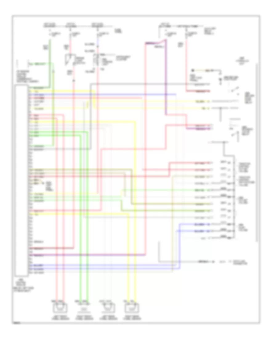
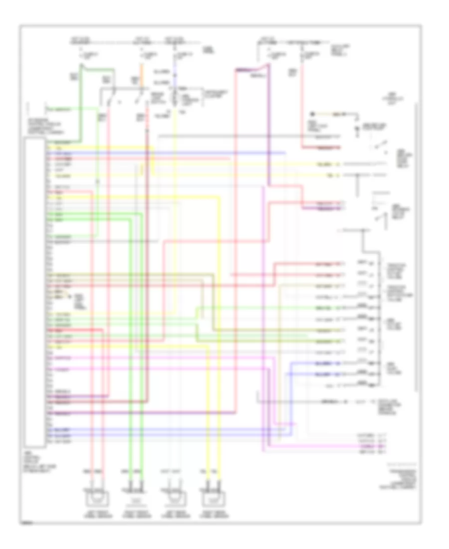
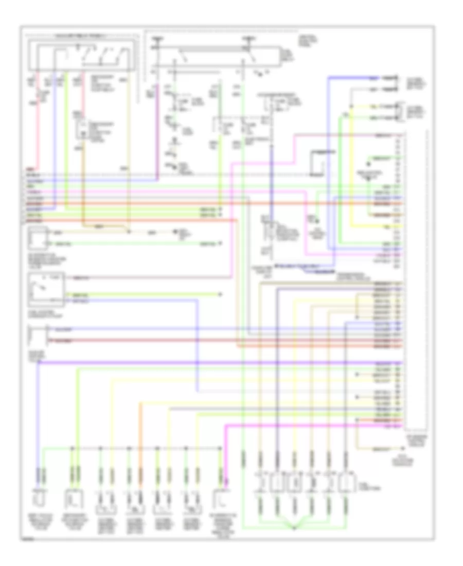
Автомтическая коробка Передач (АКПП) Полная привод (4WD) Блокировка Дифференциала
Электросхема автоматической коробки передач АКПП для Audi A6 1997
 https://portal-diagnostov.com/license.html
Automotive Electricians Portal FZCO
Automotive Electricians Portal FZCO
https://portal-diagnostov.com/license.html
https://portal-diagnostov.com/license.html
Automotive Electricians Portal FZCO
Automotive Electricians Portal FZCO
Электросхема автоматической коробки передач АКПП для Audi A6 1997 - Список элементов:
- (below left side of rear seat)
- (not used-fwd only)
- 14a
- 20a
- 28-29
- 3-4
- 44-49
- 51-52
- 87a
- Abs control module (all wheel drive)
- Acc
- Air conditioning system
- Automatic transmission console light
- Automatic transmission fuse 5a
- Auxiliary relay panel 1 (behind left side of dash)
- B11
- Battery positive terminal
- Brake light switch (on pedal cluster)
- C10
- C12
- Central electric panel (behind left side of dash)
- Computer display unit
- Cruise control system
- Data link connector (dlc) (behind console)
- Engine control module (under right footwell carpet, in electronic control box)
- Exterior lights system
- Front all wheel drive
- Fuse 10a
- Fuse 15a
- Fuse 5a
- Fuse panel (behind left side of dash)
- G900 (fwd) (lower left "a" pillar)
- G900 (lower left "a" pillar)
- Generator terminal d+
- Hot at all times
- Hot in on or start
- Ignition switch
- Instrument cluster system
- Interior lights system
- Kick down switch (on throttle valve body, or cable)
- Multi-function transmission range
- Mv1
- Mv2
- Mv3
- Nca
- Off
- Protection diode
- Red
- Red/
- Selector lever light relay
- Shift interlock system
- Shift lock solenoid (front of gear selector)
- Solenoid valves
- Start
- Switch
- T16 central locking/ alarm system/ interior light delay control module (below right side of rear seat)
- Transmission control module (tcm) (behind right kick panel)
- Transmission fluid temperature sensor
- Transmission range (tr) selector lever display
- Transmission vehicle speed sensor (front wheel drive) (left rear of engine compartment)
- Valve body
- Wheel drive
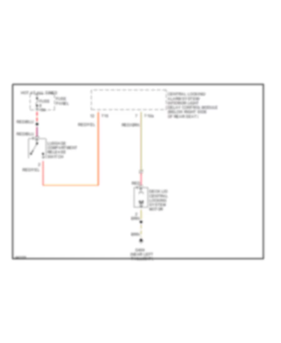
БАГАЖНИК ЗАДНЯЯ ДВЕРЬ ЛЮЧОК ТОПЛИВНОГО БАКА
Электросхема открывания багажника для Audi A6 1997
Электросхема открывания багажника для Audi A6 1997 - Список элементов:
- Central locking/ alarm system/ interior light delay control module (below right side of rear seat)
- Deck lid central locking system motor
- Fuse 15a
- Fuse panel
- G404 (near left taillight)
- Hot at all times
- Luggage compartment release switch
- Red
- T10a
- T16
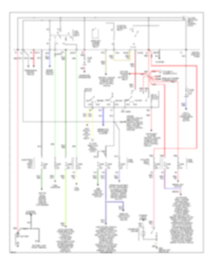
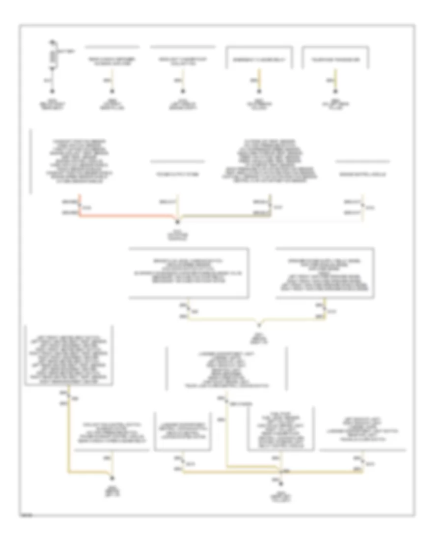
БЛОК ПРЕДОХРАНИТЕЛЕЙ И РЕЛЕ
Электросхема блока предохранителей и реле (1 из 2) для Audi A6 1997
Электросхема блока предохранителей и реле (1 из 2) для Audi A6 1997 - Список элементов:
- (not used)
- 14a
- 15a
- 17a
- 21a
- 50b
- 86s
- 87f
- A/c control head, luggage compartment light, instrument cluster, footwell lights, front interior light, make-up mirror lights, rear fog light switch, memory program switch, selector lever light relay, automatic transmission console light, multifunction transmission range switch, transmission range switch selector lever display, central locking/alarm system/ interior light delay control module, door lock switch, mirror memory control module
- Abs control module, brake light switch
- Acc
- Air bag control module, servotronic control module, shift lock relay, front power window control modules
- Auxiliary relay panel
- Battery
- Battery jump start terminal
- Brake light switch
- Central electric panel
- Central locking/ alarm system/ interior light delay control module
- Cigarette lighter
- Daytime running lights switch-on relay
- Electronic box (right foot- well)
- Engine control module
- Evap canister purge regulator valve, intake manifold change-over valve, egr vacuum regulator solenoid valve, oxygen sensors, secondary air injection pump relay
- Fuel injectors
- Fuel pump
- Fuel pump relay
- Fuse 10a
- Fuse 15a
- Fuse 20a
- Fuse 5a
- Fuse panel
- G202 (behind left side of i/p)
- Generator, instrument cluster
- Headlight dimmer/ flasher switch
- Headlight washer system relay
- Ignition coils, engine control module, mass air flow sensor
- Ignition switch
- Instrument cluster
- Interior lights system
- Key-in ignition switch
- Lamp control module, washer nozzle heaters, malfunction indicator lamp (mil), seat heater switches, central locking/ alarm system/ interior light delay control module, multifunction transmission range switch, heated mirrors, telephone transceiver
- Light switch, drl switch- on relay
- Mirror adjustment switch, instrument cluster, outside air temperature display, mirror control module, memory program switch
- Multi- function transmission range switch
- Off
- Rear fog light switch, fog light switch
- Red
- Run
- S1/50z
- S2/87f
- S3/15
- S3/s
- S4/5
- S4/50z
- S4/a
- S6/50a
- Start
- Starter
- Starter, generator
- Starting interlock relay
- Telephone transceiver
- To fuse 10 (diagram 2 of 2)
- To load reduction relay (diagram 2 of 2)
- Transmission control module
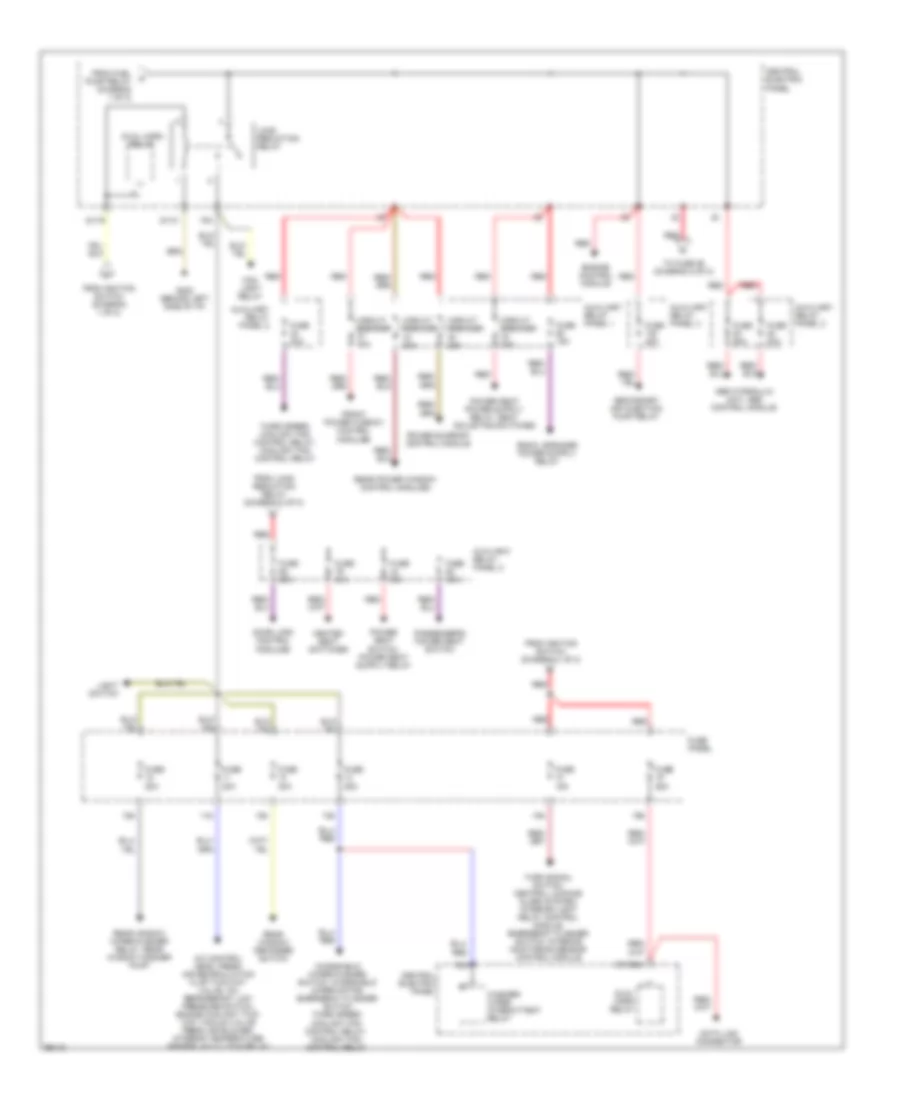
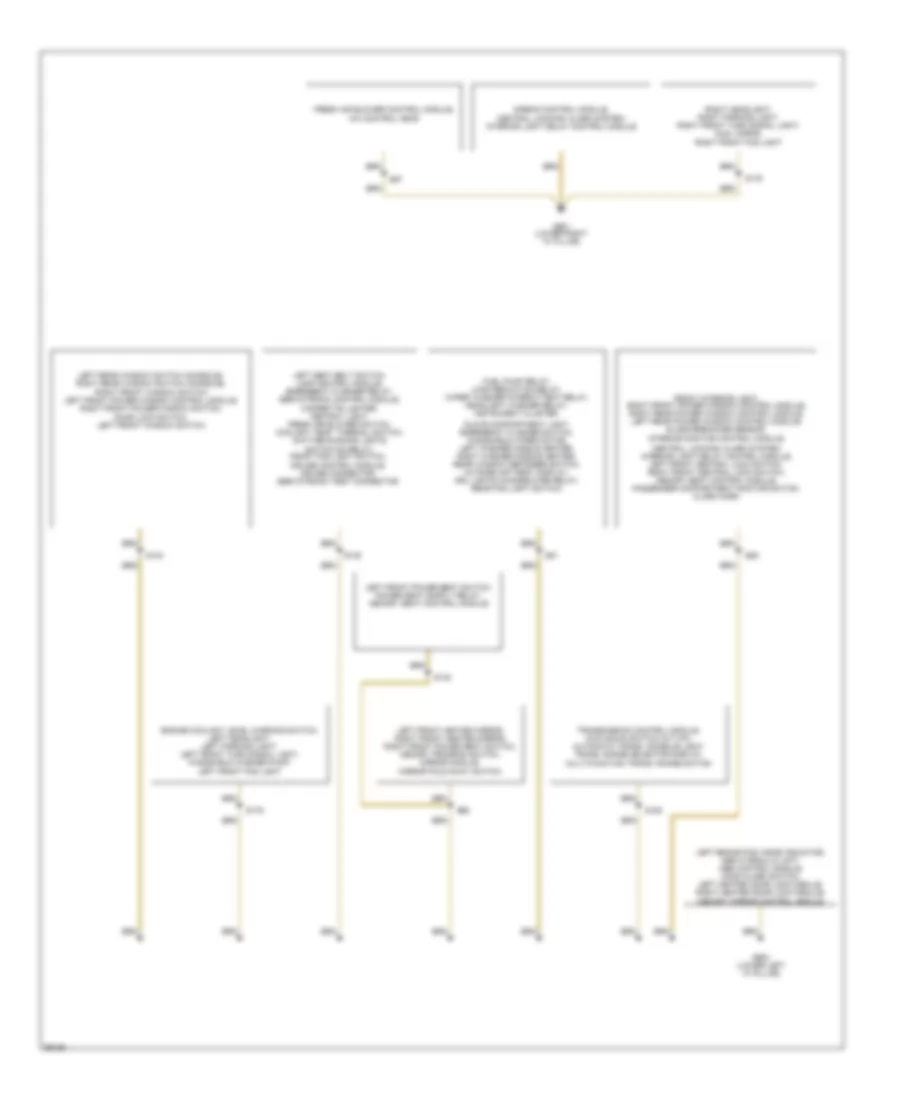
Электросхема блока предохранителей и реле (2 из 2) для Audi A6 1997
Электросхема блока предохранителей и реле (2 из 2) для Audi A6 1997 - Список элементов:
- 10a
- 11a
- 12a
- 13a
- 18a
- 19a
- 75a
- 75x
- A/c control head, fresh air recirculation flap two-way valve, a/c refrigerant low pressure switch, engine coolant two- way vacuum valve fresh air blower, interior temperature sensor, a/c clutch relay
- Abs hydraulic unit, abs control module
- Auxiliary relay panel 1
- Auxiliary relay panel 2
- Auxiliary relay panel 3
- Auxiliray relay panel 2
- Central electric panel
- Circuit breaker 20a
- Circuit breaker 30a
- Data link connector
- Door lock control modules
- Dual horn relay
- Engine control module
- Fog light relay
- From fuel pump relay (diagram 1 of 2)
- From ignition switch (diagram 1 of 2)
- From load reduction relay (diagram 2 of 2)
- Front power window control modules
- Fuse 15a
- Fuse 20a
- Fuse 25a
- Fuse 30a
- Fuse 40a
- Fuse 50a
- Fuse panel
- G202 (behind left side of i/p)
- Heated seat switches
- Light switch
- Load reduction relay
- Passenger's power seat switch
- Power sunroof control module
- Rear power window control modules
- Rear window defogger switch
- Rear window wiper/washer relay, rear window washer pump
- Red
- S1/30ah
- S1/31
- S1/75
- Secondary air injection pump relay
- Third speed coolant fan control relay, coolant fan control relay
- To fuse 86 (diagram 2 of 2)
- Turn signal switch, central locking/ alarm system/ interior light delay control module, emergency flasher switch, interior monitoring sensor control module
- Washer/ wiper intermittent relay
- Windshield wiper/washer switch, windshield wiper motor, emergency flasher switch third speed coolant fan control relay, coolant fan control relay
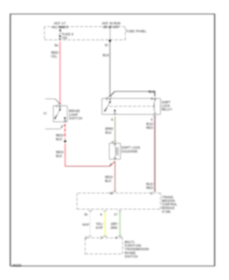
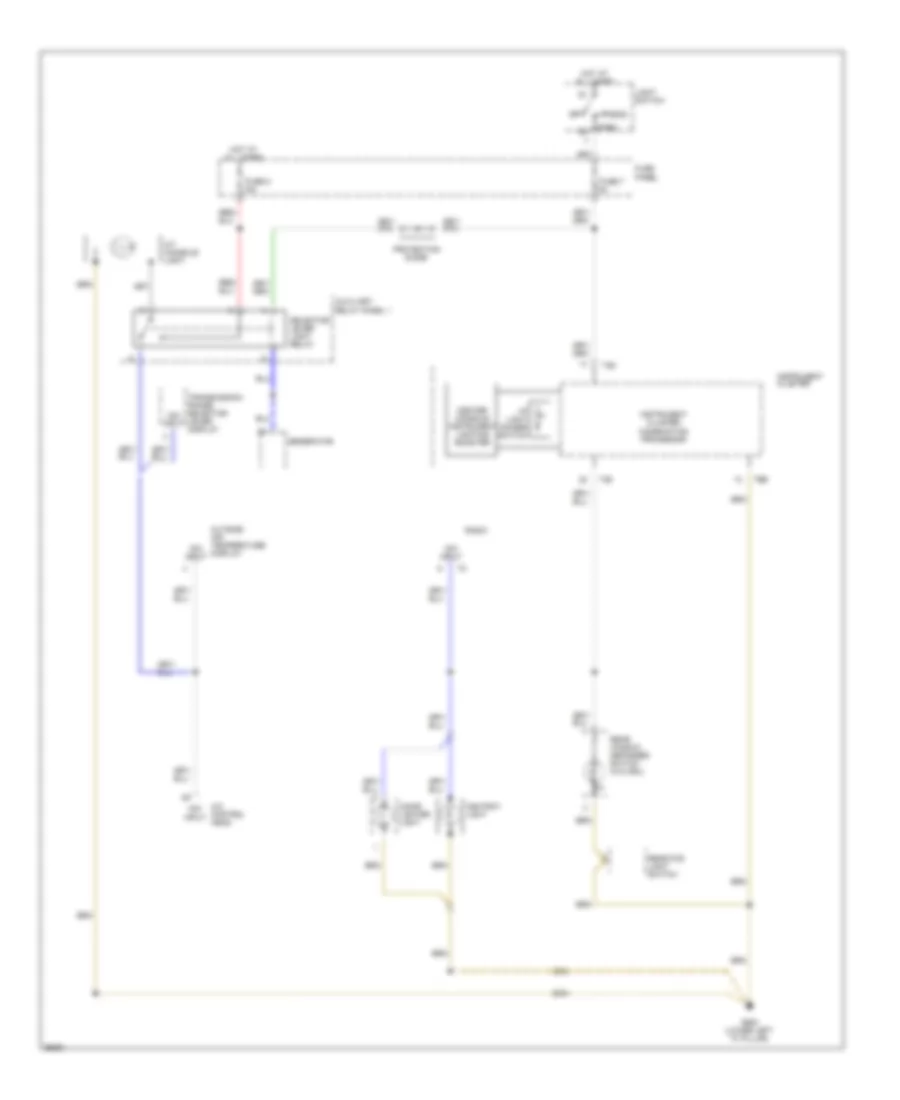
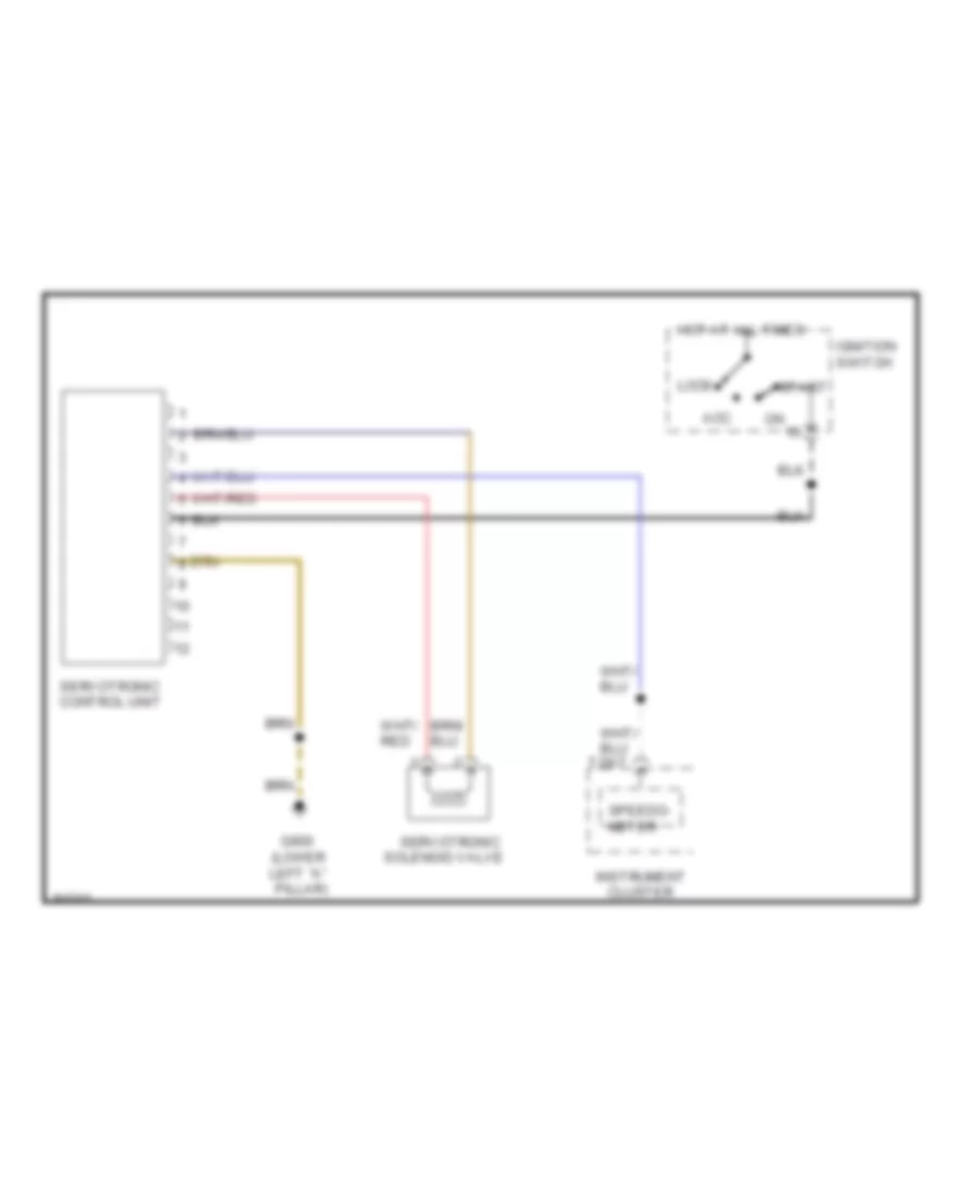
БЛОКИРОВКИ СЕЛЕКТОРА СТОЯНОЧНЫЙ ТОРМОЗ
Электросхема блокировки селектора для Audi A6 1997
Электросхема блокировки селектора для Audi A6 1997 - Список элементов:
- Brake light switch
- Fuse 9 10a
- Fuse panel
- Hot at all times
- Hot in run or start
- Multi- function transmission range switch
- Shift lock relay
- Shift lock solenoid
- Trans- mission control module (tcm)
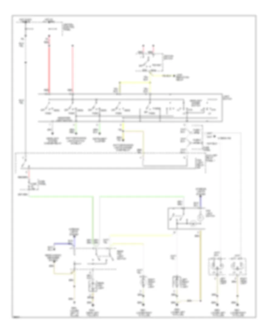
ВНЕШНЕЕ ОСВЕЩЕНИЕ
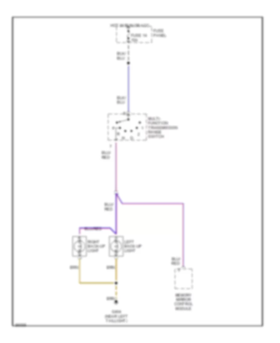
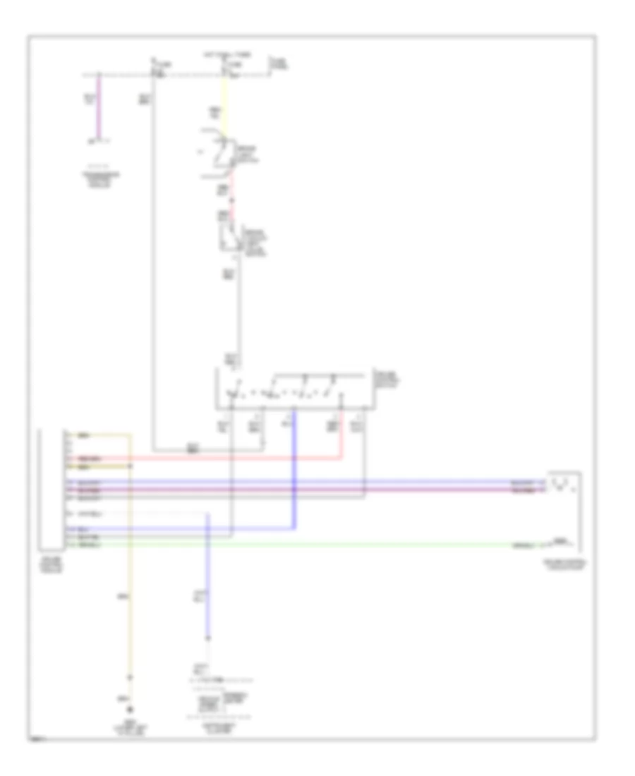
Электросхема заднего хода для Audi A6 1997
Электросхема заднего хода для Audi A6 1997 - Список элементов:
- Fuse 14 15a
- Fuse panel
- G404 (near left taillight)
- Hot in run or acc
- Left back-up light
- Memory mirror control module
- Multi- function transmission range switch
- Right back-up light
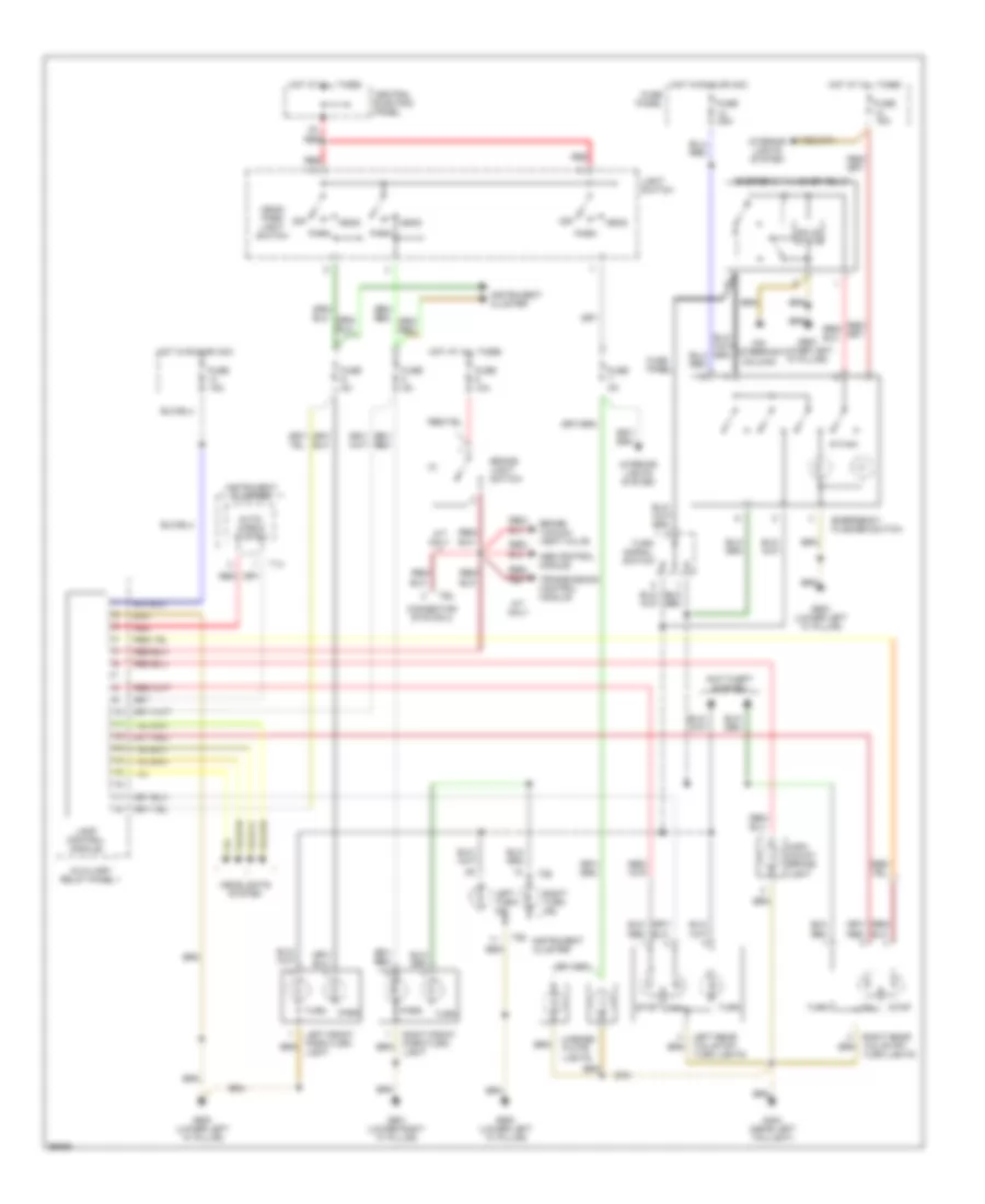
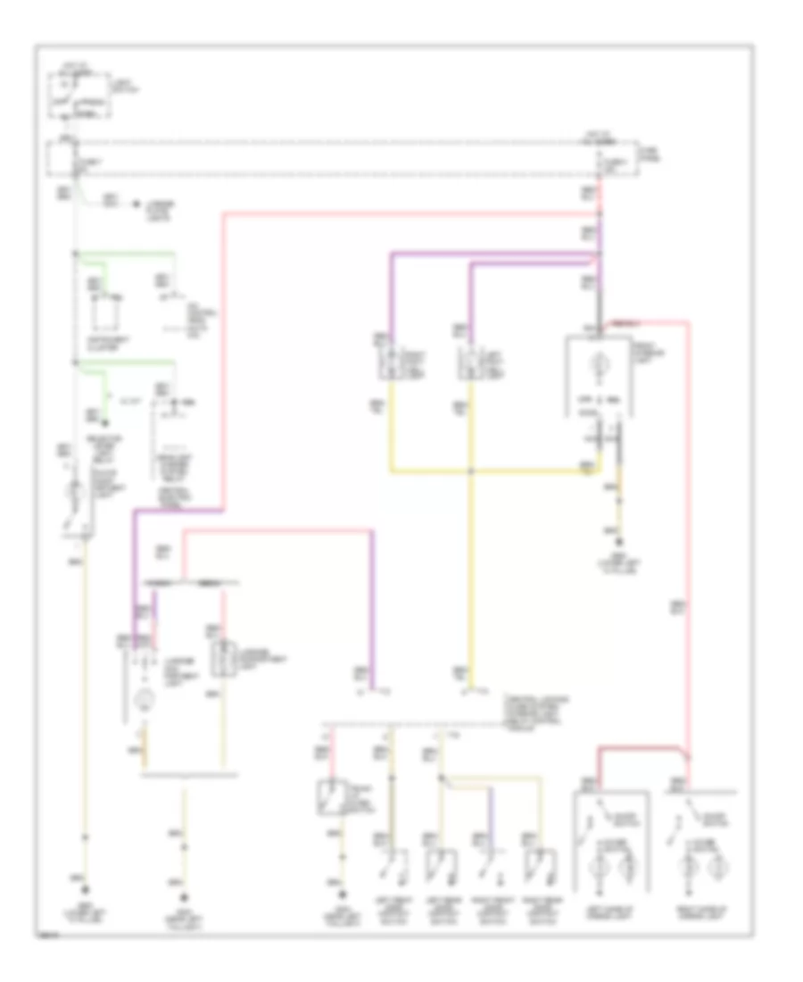
Электросхема внешнего освещения, С DRL для Audi A6 1997
Электросхема внешнего освещения, С DRL для Audi A6 1997 - Список элементов:
- (on steering column)
- A/t only
- Abs control module
- Anti-theft system
- Auto- check system
- Auxiliary relay panel 1
- Brake light switch
- Brake vacuum vent valve
- Central electric panel
- Cluster
- Connector station 2
- Daytime running lights switch- over relay
- Emergency flasher switch
- Emergency flasher relay
- Fuse 10a
- Fuse 15a
- Fuse 25a
- Fuse 5a
- Fuse panel
- G404 (near left taillight)
- G900 (lower left "a" pillar)
- G901 (lower right "a" pillar)
- Head
- Head/ park light switch
- Headlights system
- High- mount brake light
- Hot at all times
- Hot in run or acc
- Instrument
- Instrument cluster
- Interior lights system
- Lamp control module
- Left front park/turn light
- Left rear tail/stop/ turn lights
- Left turn ind.
- License plate
- Light switch
- Lights
- Off
- Park
- Red
- Right front park/turn light
- Right rear tail/stop/ turn lights
- Right turn ind.
- Signal switch
- Solid state
- Stop
- T14
- T26
- T6b
- Tail
- Transmission control module
- Turn
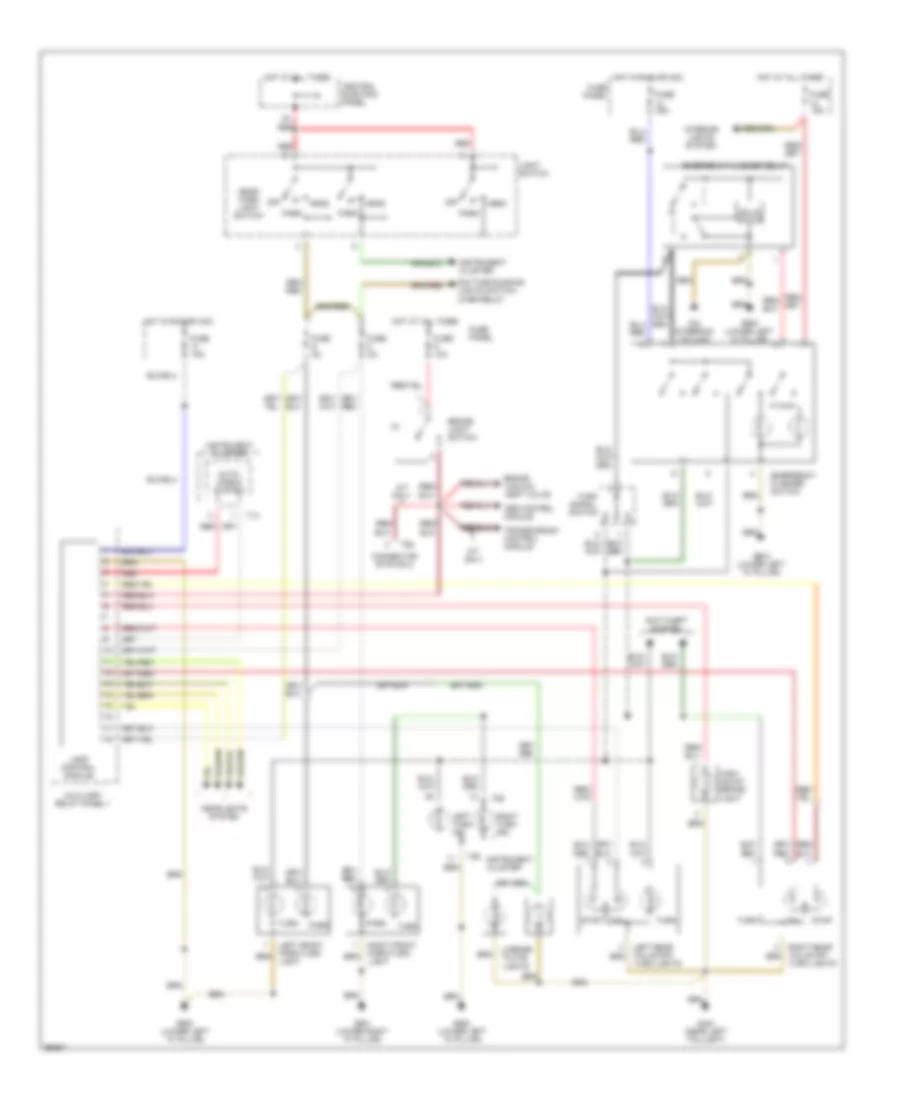
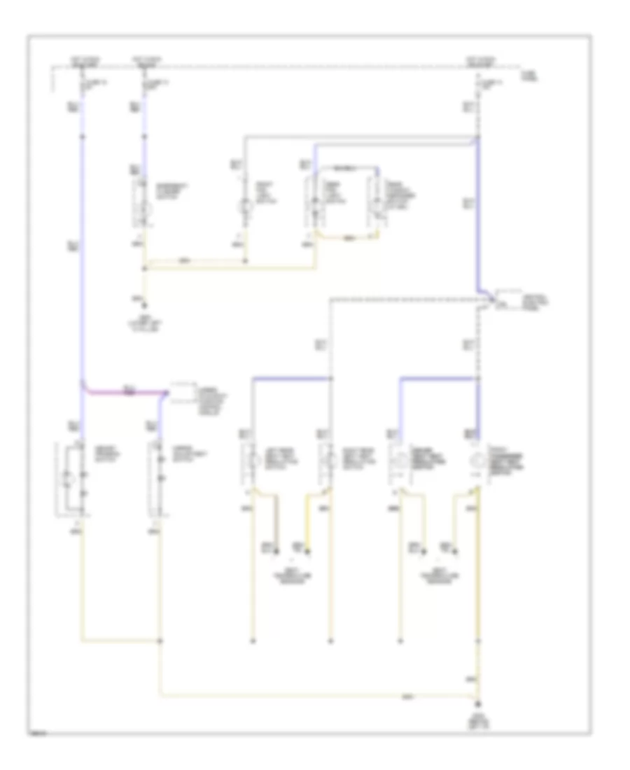
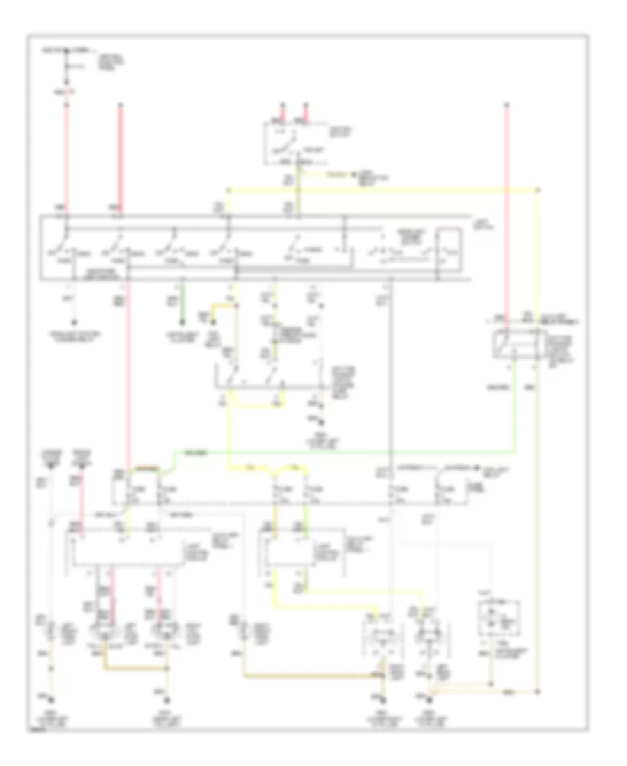
Электросхема внешнего освещения, без DRL для Audi A6 1997
Электросхема внешнего освещения, без DRL для Audi A6 1997 - Список элементов:
- (on steering column)
- A/t only
- Abs control module
- Anti-theft system
- Auto- check system
- Auxiliary relay panel 1
- Brake light switch
- Brake vacuum vent valve
- Central electric panel
- Cluster
- Connector station 2
- Emergency flasher relay
- Emergency flasher switch
- Fuse 10a
- Fuse 15a
- Fuse 25a
- Fuse 5a
- Fuse panel
- G404 (near left taillight)
- G900 (lower left "a" pillar)
- G901 (lower right "a" pillar)
- Head
- Head/ park light switch
- Headlights system
- High- mount brake light
- Hot at all times
- Hot in run or acc
- Instrument
- Instrument cluster
- Interior lights system
- Lamp control module
- Left front park/turn light
- Left rear tail/stop/ turn lights
- Left turn ind.
- License plate
- Light switch
- Lights
- Off
- Park
- Red
- Right front park/turn light
- Right rear tail/stop/ turn lights
- Right turn ind.
- Signal switch
- Solid state
- Stop
- T14
- T26
- T6b
- Tail
- Transmission control module
- Turn
ВНУТРЕННЕЕ ОСВЕЩЕНИЕ
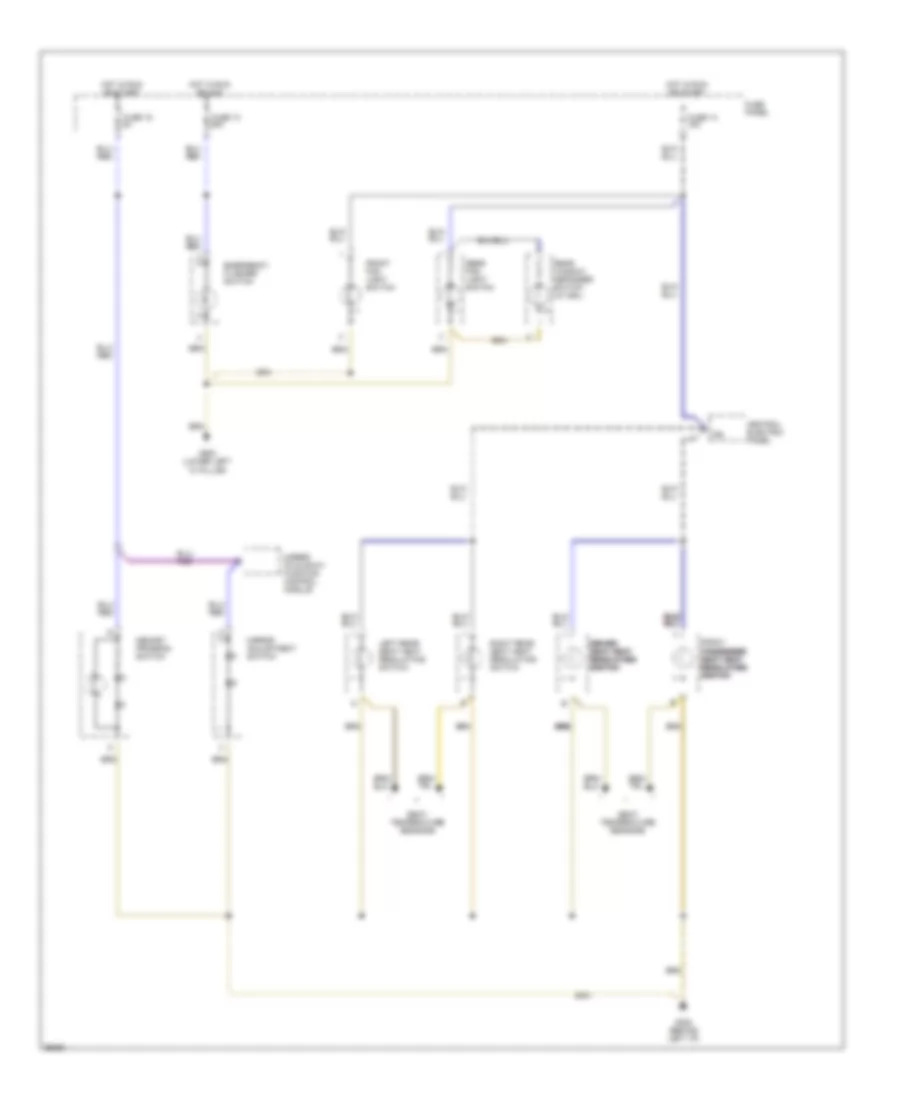
Электросхема подсветки, С Индивидуальные лампочки (1 из 2) для Audi A6 1997
Электросхема подсветки, С Индивидуальные лампочки (1 из 2) для Audi A6 1997 - Список элементов:
- (auto a/c)
- (lower left "a" pillar)
- 58a
- A/c control head
- Central electric
- Central locking/ alarm system/ interior light delay control module
- Door
- Front interior light
- Fuse 7 5a
- Fuse 8 15a
- Fuse panel
- G404 (near left taillight)
- G900
- G900 (lower left "a" pillar)
- Glove compartment light
- Head
- Headlight washer system relay
- Hot at all times
- Instrument cluster
- Left foot- well light
- Left front door contact switch
- Left front reading light
- Left rear door contact switch
- Left rear reading light
- License plate lights
- Light
- Light switch
- Luggage comp- artment light
- Luggage compartment light
- Nca
- Off
- Panel
- Park
- Right foot- well light
- Right front door contact switch
- Right front map/ reading
- Right rear door contact switch
- Right rear reading light
- Sedan
- Selector lever light relay
- T10a
- T12
- T16
- T26
- Trunk lid alarm switch
- W/ a/t
- Wagon
Электросхема подсветки, С Индивидуальные лампочки (2 из 2) для Audi A6 1997
Электросхема подсветки, С Индивидуальные лампочки (2 из 2) для Audi A6 1997 - Список элементов:
- 15a
- Central electric panel
- Driver driver driver seat heat seat heat seat heat regulating regulating regulating switch switch switch
- Emergency flasher switch
- Front
- Front fog light switch
- Fuse 13 25a
- Fuse 14 15a
- Fuse 15 5a
- Fuse panel
- G202 (behind left i/p)
- G900 (lower left "a" pillar)
- Hot in run or acc
- Hot in run or start
- Left rear seat heat regulating switch
- Memory program switch
- Mirror adjustment switch
- Mirror fold-away function control module
- Passenger passenger passenger seat heat seat heat seat heat regulating regulating regulating switch switch switch
- Rear fog light switch
- Rear window defogger switch (w/ drl)
- Right rear seat heat regulating switch
- Seat temperature sensors
Электросхема подсветки, без Индивидуальные лампочки (1 из 2) для Audi A6 1997
Электросхема подсветки, без Индивидуальные лампочки (1 из 2) для Audi A6 1997 - Список элементов:
- (auto a/c)
- 58a
- A/c control head
- Central electric
- Central locking/ alarm system/ interior light delay control module
- Cover switch
- Door
- Front interior light
- Fuse 7 5a
- Fuse 8 15a
- Fuse panel
- G404 (near left taillight)
- G900 (lower left "a" pillar)
- Glove comp- artment light
- Head
- Headlight washer system relay
- Hot at all times
- Instrument cluster
- Left foot- well light
- Left front door contact switch
- Left make-up mirror light
- Left rear door contact switch
- License plate lights
- Light switch
- Luggage com- partment light
- Luggage compartment light
- Nca
- Off
- On/off switch
- Panel
- Park
- Right foot- well light
- Right front door contact switch
- Right make-up mirror light
- Right rear door contact switch
- Sedan
- Selector lever light relay
- T10
- T12
- T16
- T26
- Trunk lid alarm switch
- W/ a/t
- Wagon
Электросхема подсветки, без Индивидуальные лампочки (2 из 2) для Audi A6 1997
Электросхема подсветки, без Индивидуальные лампочки (2 из 2) для Audi A6 1997 - Список элементов:
- 15a
- Central electric panel
- Driver driver seat heat seat heat regulating regulating switch switch
- Emergency flasher switch
- Front
- Front fog light switch
- Fuse 13 25a
- Fuse 14 15a
- Fuse 15 5a
- Fuse panel
- G202 (behind left i/p)
- G900 (lower left "a" pillar)
- Hot in run or acc
- Hot in run or start
- Left rear seat heat regulating switch
- Memory program switch
- Mirror adjustment switch
- Mirror fold-away function control module
- Passenger passenger seat heat seat heat regulating regulating switch switch
- Rear fog light switch
- Rear window defogger switch (w/ drl)
- Right rear seat heat regulating switch
- Seat temperature sensors
Электросхема подсветки приборов для Audi A6 1997
Электросхема подсветки приборов для Audi A6 1997 - Список элементов:
- A/c control head
- A/t console light
- Ashtray light
- Auxiliary relay panel 1
- Center console instrument lighting booster
- Cigar lighter light
- Dim input
- Fuse 7 5a
- Fuse 8 15a
- Fuse panel
- G900 (lower left "a" pillar)
- Generator
- Head
- Hot at all times
- I/p light dimmer switch
- Instrument cluster
- Instrument cluster combination processor
- Light switch
- Off
- Outside air temperature display
- Park
- Protection diode
- Radio
- Rear fog light switch
- Rear window defogger switch (w/o drl)
- Selector lever light relay
- T26
- T26 t26
- Transmission range selector lever display
ЗАЗЕМЛЕНИЕ ПОДКЛЮЧЕНИЕ МАССЫ
Электросхема подключение массы заземления (1 из 2) для Audi A6 1997
Электросхема подключение массы заземления (1 из 2) для Audi A6 1997 - Список элементов:
- Battery
- Brake fluid level warning switch, vehicle speed sensor, kick down switch (a/t 01k), evaporative emission canister purge solenoid valve, secondary air injection pump relay, secondary air injection pump motor
- Camshaft position sensor, mass air flow sensor, throttle position sensor, engine coolant temp. sensor, egr temp. sensor, engine control module, mass air flow sensor shield, knock sensor shields, camshaft position sensor shield, engine speed sensor shield, oxygen sensor shields
- Coolant fan control switch, sunroof motor, a/c high pressure switch, power sunroof control module, rear window wiper/washer relay
- Emergency flasher relay
- Engine control module
- Fuel pump, fuel level sensor, left taillight, high mount brake light, right taillight, rear washer pump, central locking/alarm system/ interior light delay control module
- G104 (left side of engine compt)
- G131 (on intake manifold)
- G201 (behind right i/p)
- G202 (behind left i/p)
- G207 (on steering column)
- G303 (below right rear seat)
- G404 (near left taillight)
- G904 (on left rear pillar)
- G905 (on right rear pillar)
- Headlight washer pump, coolant fan
- Left backup light, right backup light, license lamps, luggage compartment light switch, rear fog light, trunklid alarm switch
- Left front heated seat switch, left front heated seat temp. sensor, left front backrest heater, right front heated seat switch, right front heated seat temp. sensor, right front backrest heater, left rear heated seat switch, left rear heated seat temp. sensor, left rear backrest heater, right rear heated seat switch, right rear heated seat temp. sensor, right rear backrest heater
- Luggage compartment central locking switch, decklid central locking system motor
- Luggage compartment light, license lights, left back-up light, right back-up light, rear fog light, rear defogger, rear wiper motor, high mount brake light, trunk lock alarm/central locking switch
- Outside air temp. sensor, a/c high pressure switch, a/c compressor speed sensor, headliner interior temp. sensor, fresh air intake temp. sensor, fresh air blower temp. sensor, i/p interior temp. sensor, back pressure flap motor position sensor, temp. regulator flap motor position sensor, footwell/ defrost flap motor position sensor, central flap motor position sensor,
- Power output stage
- Rear window defogger, antenna amplifier
- S127
- S133
- S182
- S183
- S218
- S219
- S85
- S86
- S96
- S96 (wagon)
- Telephone transceiver
Электросхема подключение массы заземления (2 из 2) для Audi A6 1997
Электросхема подключение массы заземления (2 из 2) для Audi A6 1997 - Список элементов:
- Airbag control module, central locking/ alarm system/ interior light delay control module
- Central locking/ alarm system/ interior light delay control module, left front central lock switch, right front central lock switch, memory seat control module, passenger compartment monitor switch, alarm horn
- Engine coolant level warning switch, left headlight, left parking light, left front turn signal light, windshield washer pump, left front fog light
- Fresh air blower control module, a/c control head
- Front interior light, right front power window control module, right rear power window control module, left rear power window control module, glass breakage sensor, interior monitor control module,
- Fuel pump relay, load reduction relay, wiper/ washer intermittent relay, headlight washer relay, instrument cluster,
- G900 (lower left "a" pillar)
- G901 (lower right "a" pillar)
- Glove compartment light, emergency flasher switch, windshield wiper motor, left washer nozzle heater, right washer nozzle heater, rear window defogger switch, outside air temp. display, drl lights change-over relay, rear fog light switch,
- Left brake pad wear indicator, abs hydraulic unit, abs control module, hood alarm switch, left heated door lock module, right heated door lock module, memory mirror control module
- Left front heated mirror, right front heated mirror, right front power seat switch, memory program switch, mirror module, mirror fold-away switch
- Left rear window switch (console), right rear window switch (console), right front window switch left front power window control module, right front power window switch, door lock switch, left front window switch
- Left seat belt switch, lamp control module, emergency flasher relay, servotronic control module, cigarette lighter, ashtray light, fresh air blower switch, coolant temp. thermal switch, daytime running lights switch-on relay, front fog light switch, cruise control module, cruise connector, servotronic test connector
- Right headlight, right parking light, right front turn signal light, dual horns, right front fog light
- S103
- S135
- S140
- S150
- S176
- S179
- S81
- S89
- S95
- S97
- Transmission control module, kick down switch (a/t 01f), automatic trans. console light, trans. range selector display, multi-function trans. range switch
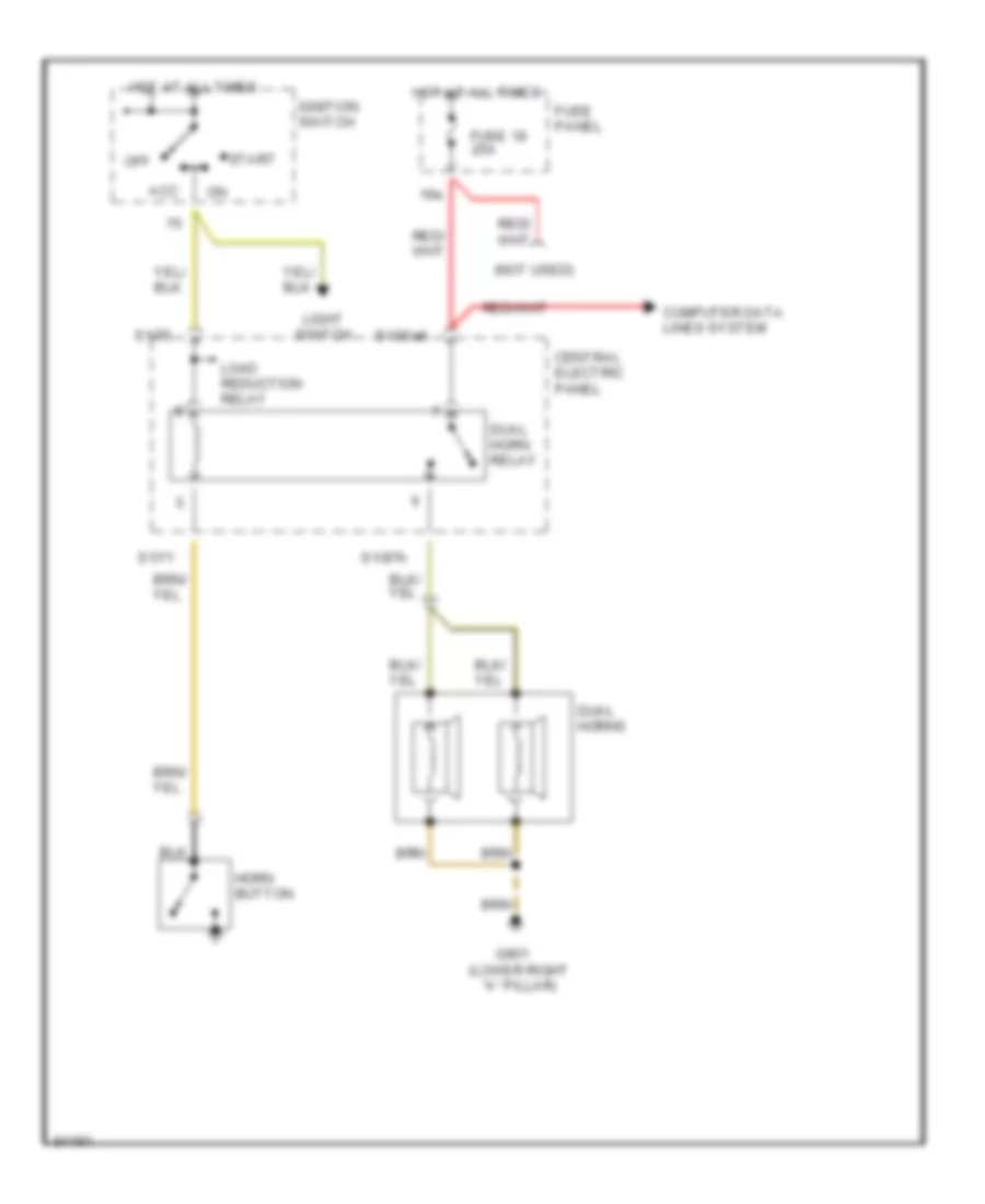
Звуковой сигнал Гудок
Электросхема звукового сигнал Гудка для Audi A6 1997
Электросхема звукового сигнал Гудка для Audi A6 1997 - Список элементов:
- (not used)
- 19a
- Acc
- Central electric panel
- Computer data lines system
- Dual horn relay
- Dual horns
- Fuse 19 25a
- Fuse panel
- G901 (lower right "a" pillar)
- Horn button
- Hot at all times
- Ignition switch
- Light switch
- Load reduction relay
- Off
- S1/30ah
- S1/71
- S1/75
- S1/87h
- Start
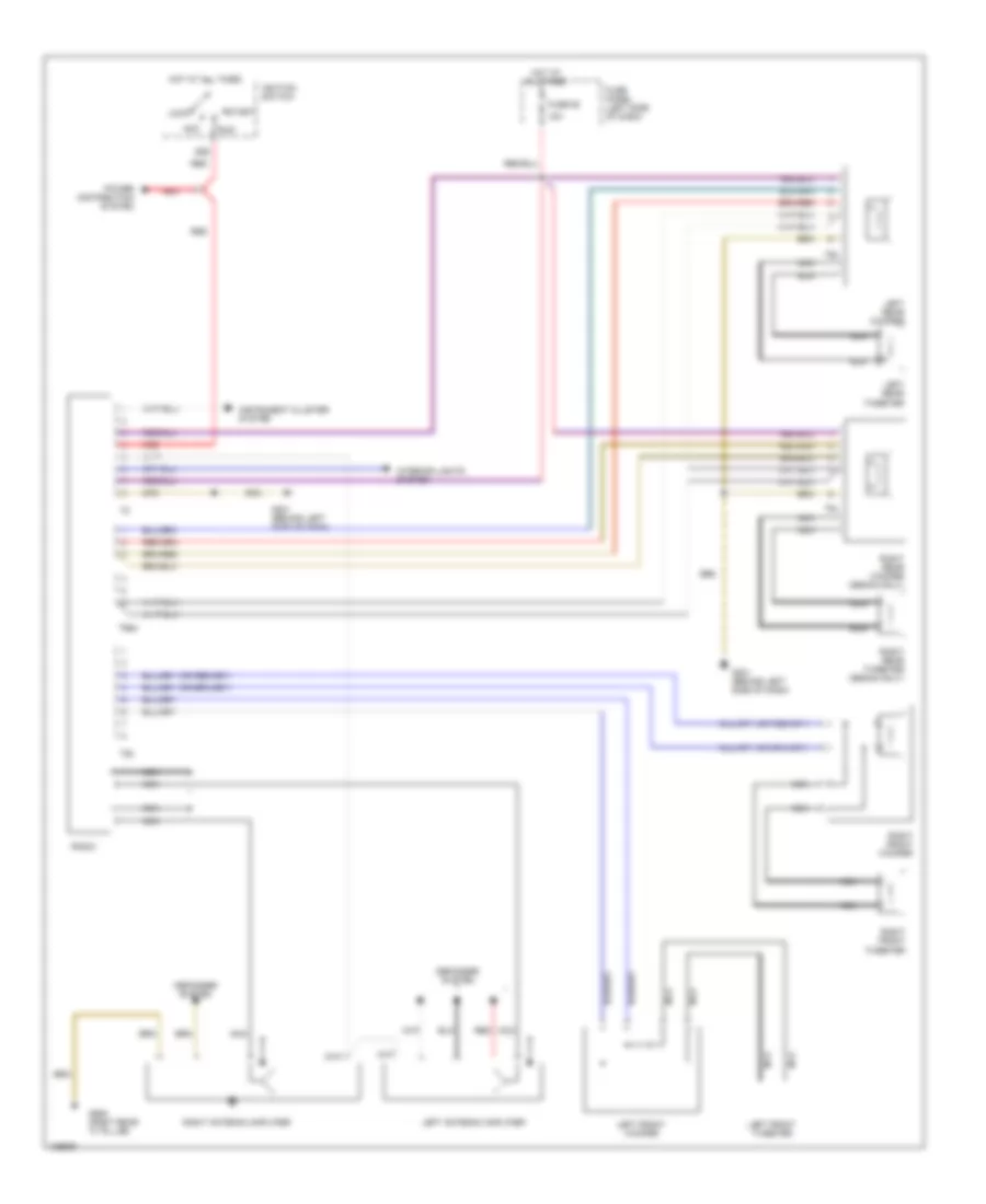
Магнитола Мультимедия
Электросхема магнитолы, Стандартная комплектация для Audi A6 1997
Электросхема магнитолы, Стандартная комплектация для Audi A6 1997 - Список элементов:
- 15a
- 86s
- Acc
- Defogger system
- Fuse 92
- Fuse panel (left side of dash)
- G201 (behind left side of dash)
- G905 (right rear "c" pillar)
- Hot at all times
- Ignition switch
- Instrument cluster system
- Interior lights system
- Left antenna amplifier
- Left front tweeter
- Left front woofer
- Left rear tweeter
- Left rear woofer
- Lock
- Nca
- Power distribution system
- Radio
- Red
- Right antenna amplifier
- Right front tweeter
- Right front woofer
- Right rear tweeter (sedan only)
- Right rear woofer (sedan only)
- Run
- Start
- T5b
- T5c
- T6aw
- T8b
Электросхема магнитолы, седан С Bose для Audi A6 1997
Электросхема магнитолы, седан С Bose для Audi A6 1997 - Список элементов:
- 15a
- 1995 vftc c
- 86s
- Acc
- Amplifier
- Defogger system
- Door locks system
- Fuse 92
- Fuse panel (left side of dash)
- G203 (right kick panel)
- G905 (right rear "c" pillar)
- Hot at all times
- Ignition switch
- Instrument cluster system
- Interior lights system
- Left antenna amplifier
- Left front amplified speaker
- Left rear speaker
- Left rear tweeter
- Left rear woofer
- Lock
- Nca
- Power distribution system
- Radio
- Red
- Right antenna amplifier
- Right front amplified speaker
- Right rear speaker
- Right rear tweeter
- Right rear woofer
- Run
- Start
- T1i
- T6aw
Электросхема магнитолы, Универсал С Bose для Audi A6 1997
Электросхема магнитолы, Универсал С Bose для Audi A6 1997 - Список элементов:
- 15a
- 86s
- Acc
- Amplifier
- Antenna amplifier
- Door locks system
- Fuse 92
- Fuse panel (left side of dash)
- G203 (right kick panel)
- Hot at all times
- Ignition switch
- Instrument cluster system
- Interior lights system
- Left front amplified speaker
- Left rear tweeter
- Left rear woofer
- Lock
- Nca
- Power distribution system
- Radio
- Red
- Right front amplified speaker
- Right rear tweeter
- Right rear woofer
- Run
- Start
- T1i
- T6aw
- T6ba
- T6bb
Подогрев стекол и зеркал
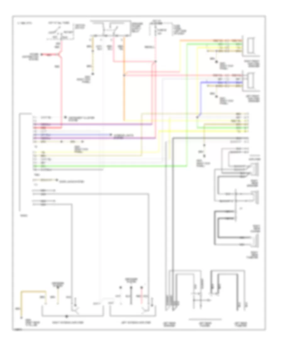
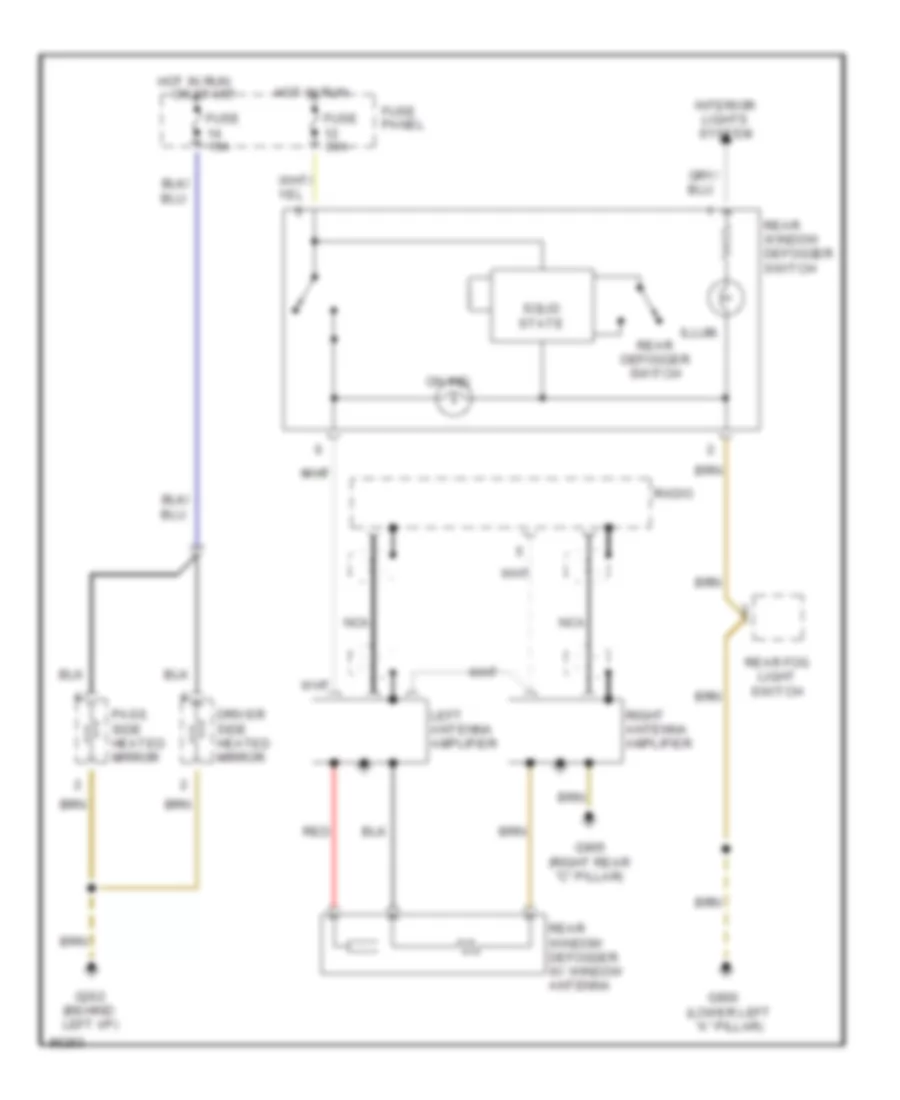
Электросхема подогрева стекол и зеркал, С Усилитель Антенны для Audi A6 1997
Электросхема подогрева стекол и зеркал, С Усилитель Антенны для Audi A6 1997 - Список элементов:
- Driver side heated mirror
- Fuse 15a
- Fuse 30a
- Fuse panel
- G202 (behind left i/p)
- G900 (lower left "a" pillar)
- G905 (right rear "c" pillar)
- Hot in run
- Illum.
- Interior lights system
- Left antenna amplifier
- Nca
- On ind.
- Or start
- Pass. side heated mirror
- Radio
- Rear defogger switch
- Rear fog light switch
- Rear window defogger switch
- Rear window defogger w/ window antenna
- Red
- Right antenna amplifier
- Solid state
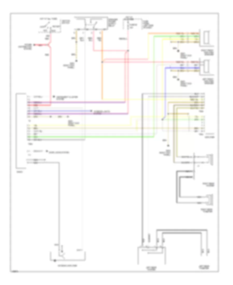
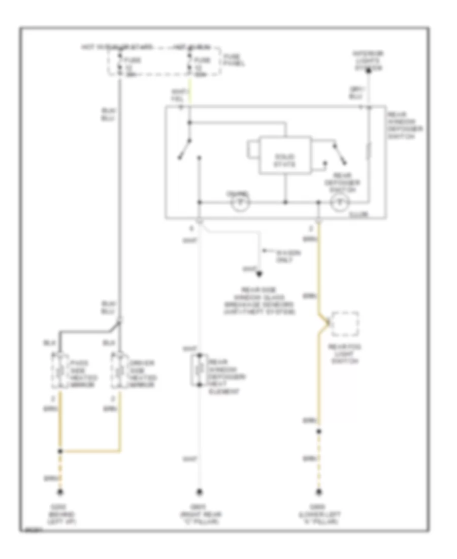
Электросхема подогрева стекол и зеркал, без Усилитель Антенны для Audi A6 1997
Электросхема подогрева стекол и зеркал, без Усилитель Антенны для Audi A6 1997 - Список элементов:
- Driver side heated mirror
- Fuse 30a
- Fuse panel
- G202 (behind left i/p)
- G900 (lower left "a" pillar)
- G905 (right rear "c" pillar)
- Hot in run
- Hot in run or start
- Illum.
- Interior lights system
- On ind.
- Pass. side heated mirror
- Rear defogger switch
- Rear fog light switch
- Rear side window glass breakage sensors (anti-theft system)
- Rear window defogger switch
- Rear window defogger/ heat element
- Solid state
- Wagon only
ПОДУШКИ БЕЗОПАСНОСТИ AIR BAG
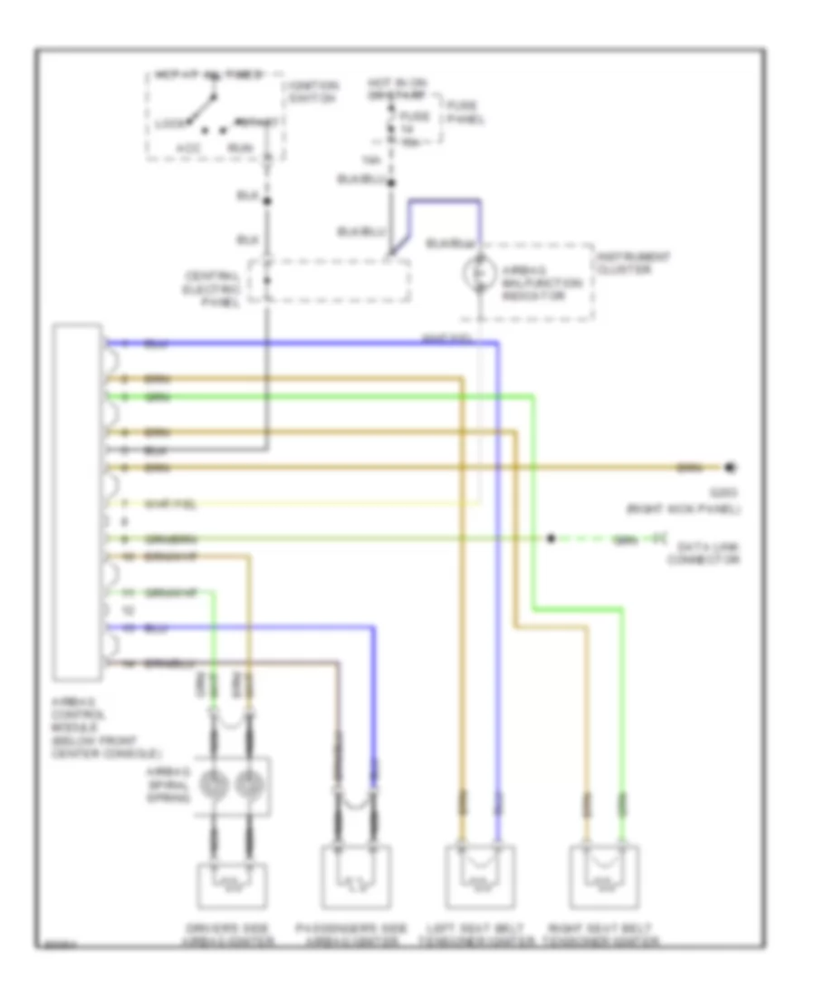
Электросхема подушек безопасности SRS AirBag для Audi A6 1997
Электросхема подушек безопасности SRS AirBag для Audi A6 1997 - Список элементов:
- (right kick panel)
- 14a
- Acc
- Airbag control module (below front center console)
- Airbag malfunction indicator
- Airbag spiral spring
- Central electric panel
- Data link connector
- Driver's side airbag igniter
- Fuse 15a
- Fuse panel
- G203
- Hot at all times
- Hot in on or start
- Ignition switch
- Instrument cluster
- Left seat belt tensioner igniter
- Lock
- Nca
- Passenger's side airbag igniter
- Right seat belt tensioner igniter
- Run
- Start
ПРЕДУПРЕЖДАЮЩИЕ СИСТЕМЫ
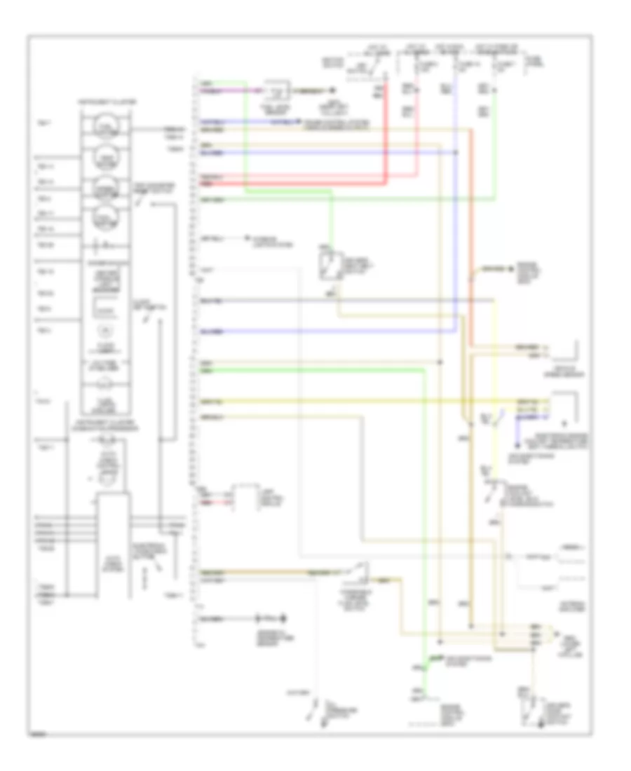
Электросхема предупреждающей системы для Audi A6 1997
Электросхема предупреждающей системы для Audi A6 1997 - Список элементов:
- (6 bulbs)
- 86s
- Air conditioning system
- Antenna amplifier
- Auto check system
- Auto- check control lights
- C10
- Center console light booster
- Clock
- Clock light
- Clock set button
- Cruise control system (vehicle speed output)
- Dimmer switch
- Driver's door contact switch
- Driver's seat belt switch
- Electronic engine coolant temperature (ect) thermal switch
- Electronic voice check button
- Engine control module (ecm)
- Engine coolant level (elc) warning switch
- Engine oil
- Fluid level
- Fuel gauge
- Fuel level sensor
- Fuse 15 5a
- Fuse 7 5a
- Fuse 8 15a
- Fuse panel
- G404 (near left taillight)
- G900 (lower left "a"pillar)
- Hot at all times
- Hot in run or acc
- Hot w/ park or headlights on
- Ignition switch
- Illum. lights
- Instrument cluster
- Instrument cluster combination processor
- Interior lights system
- Key switch
- Lamp control module
- Oil pressure switch
- Radio
- Red
- Sensor
- Speed- ometer
- Switch
- T14
- T14-1
- T14-11
- T14-12
- T14-2
- T14-8
- T26
- T26-10
- T26-11
- T26-14
- T26-15
- T26-17
- T26-18
- T26-2
- T26-22
- T26-26
- T26-3
- T26-7
- T26-8
- T26a
- T26a-11
- T26a-12
- T26a-16
- T26a-3
- T26a-6
- T26a-7
- T26a-9
- T4m
- T4m-2
- T8/5
- Tach- ometer
- Temp gauge
- Temperature
- Trip odometer reset switch
- Vehicle speed sensor
- Voltage stabilizer
- Washer
- Windshield
ПРИБОРНАЯ ПАНЕЛЬ
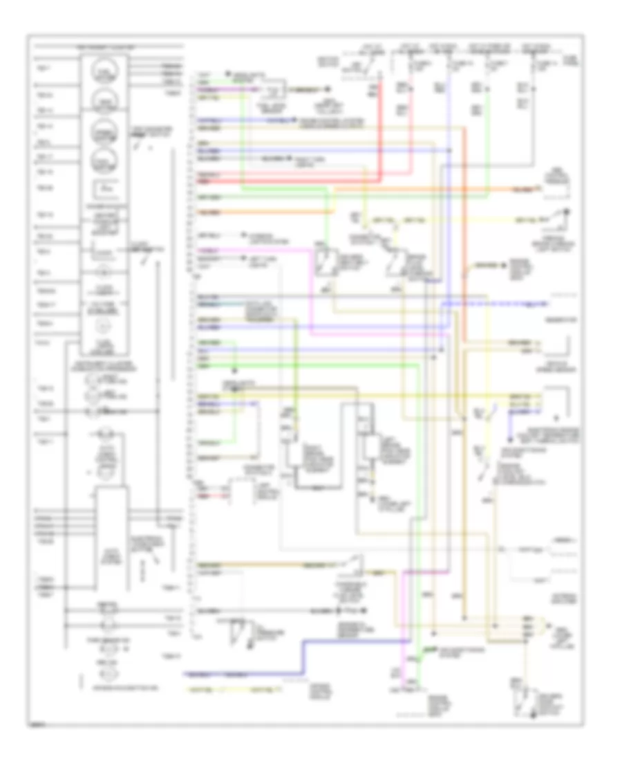
Электросхема панели приборов для Audi A6 1997
Электросхема панели приборов для Audi A6 1997 - Список элементов:
- (6 bulbs)
- 86s
- Abs control module
- Abs ind.
- Air bag control module
- Air bag malfunction ind.
- Air conditioning system
- Antenna amplifier
- Auto check system
- Auto- check control lights
- Brake fluid level warning switch
- C10
- C22
- Center console light booster
- Clock
- Clock light
- Clock set button
- Connector station 1
- Connector station 2
- Cruise control system (vehicle speed output)
- Data link connector (rapid data transfer)
- Dimmer switch
- Driver's door contact switch
- Driver's seat belt switch
- Electronic engine coolant temperature (ect) thermal switch
- Electronic voice check button
- Engine control module (ecm)
- Engine coolant level (elc) warning switch
- Engine oil
- Fluid level
- Fuel gauge
- Fuel level sensor
- Fuse 14 15a
- Fuse 15 5a
- Fuse 7 5a
- Fuse 8 15a
- Fuse panel
- G404 (near left taillight)
- G900 (lower left "a" pillar)
- G900 (lower left "a"pillar)
- Gen ind.
- Generator
- Headlights system
- Hi beam ind.
- Hot at all times
- Hot in run or acc
- Hot in run or start
- Hot w/ park or headlights on
- Ignition switch
- Illum. lights
- Instrument cluster
- Instrument cluster combination processor
- Interior lights system
- Key switch
- Lamp control module
- Left brake pad wear indicator element
- Left turn ind.
- Left turn lights
- Nca
- Oil pressure switch
- Park brake ind.
- Parking brake warning light switch
- Radio
- Red
- Right brake pad wear indicator element
- Right turn ind.
- Right turn lights
- Sensor
- Speed- ometer
- Switch
- T14
- T14-1
- T14-11
- T14-12
- T14-2
- T14-8
- T26
- T26-1
- T26-10
- T26-11
- T26-12
- T26-14
- T26-15
- T26-17
- T26-18
- T26-19
- T26-2
- T26-22
- T26-24
- T26-25
- T26-26
- T26-3
- T26-4
- T26-7
- T26-8
- T26a
- T26a-10
- T26a-11
- T26a-12
- T26a-16
- T26a-17
- T26a-22
- T26a-24
- T26a-3
- T26a-4
- T26a-6
- T26a-7
- T26a-9
- T4m
- T4m-2
- T8/5
- Tach- ometer
- Temp gauge
- Temperature
- Trip odometer reset switch
- Vehicle speed sensor
- Voltage stabilizer
- Washer
- Windshield
ПРИВОД ЛЮКА И КРЫШИ
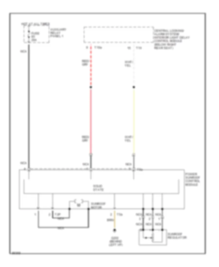
Электросхема привода люка для Audi A6 1997
Электросхема привода люка для Audi A6 1997 - Список элементов:
- Auxiliary relay panel 1
- Central locking/ alarm system/ interior light delay control module (below right rear seat)
- Fuse 20a
- G202 (behind left i/p)
- Hot at all times
- Nca
- Power sunroof control module
- Solid state
- Sunroof motor
- Sunroof regulator
- T10a
- T16
- T2p
- T5a
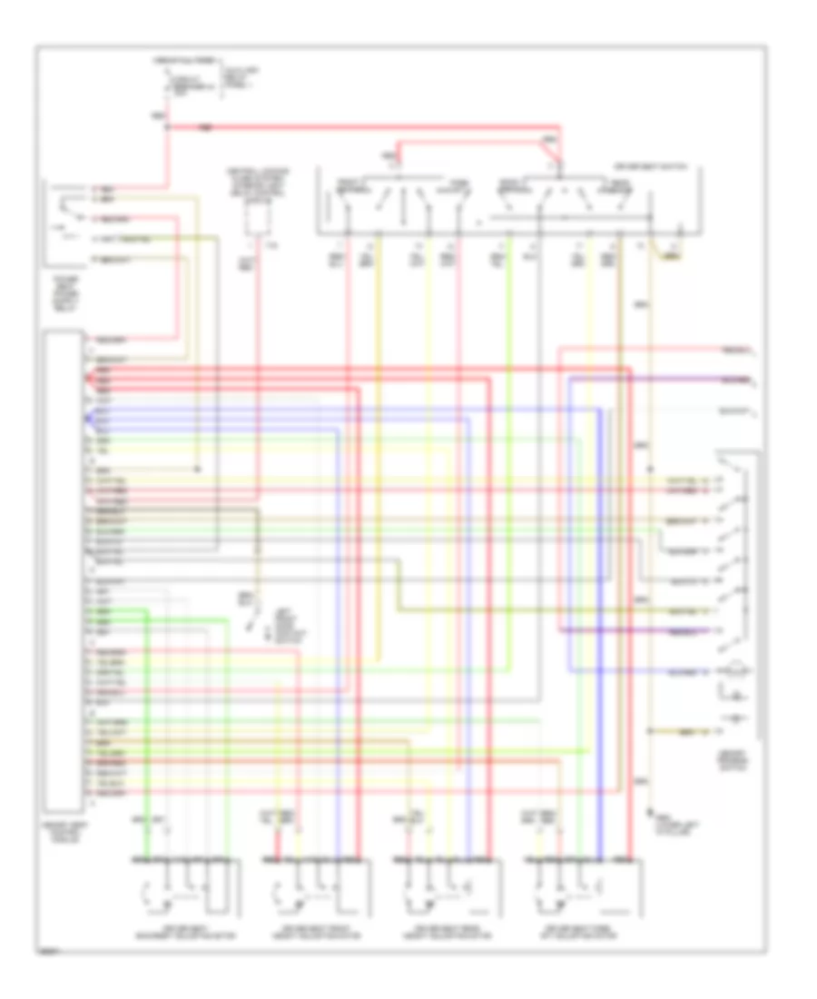
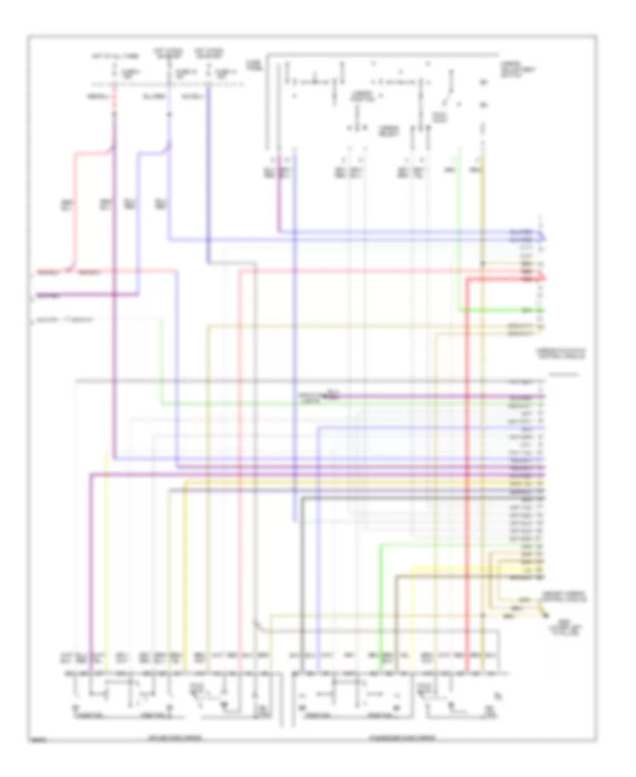
ПРИВОД СТЕКЛОПОДЪЕМНИКОВ
системная монтажная схема окна со стеклоподъемником (схема A6 1 из 2) для Audi A6 1997
системная монтажная схема окна со стеклоподъемником (схема A6 1 из 2) для Audi A6 1997 - Список элементов:
- All times
- Auxiliary relay panel 1 (left kick panel)
- Central locking/ alarm system/ interior light delay control module (below right side of rear seat)
- Driver's door contact switch
- Front power window circuit breaker 37 30a
- Fuse panel (behind left side of i/p)
- G900 (lower left a-pillar)
- Hot at
- Hot in on or acc
- Left front window switch
- Left rear door contact switch
- Left window motor
- Passenger's door contact switch
- Power sunroof control module
- Right window motor
- Right front door window switch (door)
- Right front door window switch (left front door)
- Right rear door contact switch
- Window motor
системная монтажная схема окна со стеклоподъемником (схема A6 2 из 2) для Audi A6 1997
системная монтажная схема окна со стеклоподъемником (схема A6 2 из 2) для Audi A6 1997 - Список элементов:
- All times
- Auxiliary relay panel 1 (left kick panel)
- G900 (lower left a-pillar)
- Hot at
- Left rear door window motor
- Left rear door window switch (center console)
- Left rear door window switch (door)
- Rear power window circuit breaker 43 30a
- Right rear door window motor
- Right rear door window switch (center console)
- Right rear door window switch (door)
- Window lockout switch
- Window motor
Противоугонная система Сигнализация
противоугонная и центральная схема захвата (1 из 2) для Audi A6 1997
противоугонная и центральная схема захвата (1 из 2) для Audi A6 1997 - Список элементов:
- (lower left
- 10a
- 14a
- 15/a
- 15a
- 17/50a
- 19/50z
- 20/b
- 86s
- A-pillar)
- Acc
- Alarm switch
- All times
- Antenna
- Auxiliary relay panel 1
- B11
- Battery
- Central electric panel
- Central locking/ alarm system/ interior light delay control module (below right rear seat)
- Data link connector
- Door lock switch
- Driver's door central locking system switch
- Emergency flasher
- Engine control module (ecm)
- Exterior lights system
- Function transmission range switch
- Fuse 15a
- Fuse panel
- G131 (intake manifold)
- G404 (near left
- G900
- G900 (lower left a-pillar)
- Hood
- Horn
- Hot at
- Hot in run
- Ignition switch
- Instrument cluster combination processor
- Interior lights system
- Interlock
- Key switch
- Memory systems
- Multi-
- Nca
- Off
- Or acc
- Passenger's door central locking system switch
- Power windows system
- Radio
- Red
- Relay
- S1/50z
- S4/50z
- S4/a
- S4/b
- S6/50a
- Start
- Starter
- T10
- T12
- T16
- T26/7
- T26a/18
- Taillight)
- Trunk lid alarm switch
- Trunk lock alarm/ central locking switch
- Trunk release system
противоугонная и центральная схема захвата (2 из 2) для Audi A6 1997
противоугонная и центральная схема захвата (2 из 2) для Audi A6 1997 - Список элементов:
- Alarm ind
- Blower motor
- G900 (lower left a-pillar)
- Interior monitoring sensors control module
- Interior monitoring switch
- Left front door contact switch
- Left interior monitoring sensor
- Left rear door contact switch
- Left rear side window breakage sensor
- Motor blower
- Nca
- Rear fog light switch
- Rear window defogger
- Rear window defogger switch
- Right front door contact switch
- Right interior monitoring sensor
- Right rear door contact switch
- Right rear side window breakage sensor
- Sedan only
- Wagon only
СИСТЕМА АНТИБЛОКИРОВОЧНОЙ ТОРМОЗНОЙ СИСТЕМЫ ABS
Электросхема антиблокировочной тормозной системы АБС (ABS), БУДУЩАЯ для Audi A6 1997
Электросхема антиблокировочной тормозной системы АБС (ABS), БУДУЩАЯ для Audi A6 1997 - Список элементов:
- (below left side
- Abs
- Abs inlet valves
- Abs outlet valves
- Abs return flow pump
- Abs return flow pump relay
- Abs solenoid valve relay
- Abs warning light
- All times
- Auxiliary relay panel 2
- Brake lamp switch
- Control
- Data link connector
- Fuse 15 5a
- Fuse 21 10a
- Fuse 53 50a
- Fuse 54 30a
- Fuse 9 10a
- Fuse panel
- G200 (left kick panel)
- Hot at
- Hot at all times
- Hot in on or start
- Hydraulic
- Instrument cluster
- Left front wheel sensor
- Left rear wheel sensor
- Mfi engine control module (under right footwell carpet)
- Module
- Of rear seat)
- Red
- Right front wheel sensor
- Right rear wheel sensor
- T26
- T26a
- Traction control outlet valves
- Traction control switch-over valves
- Unit
Электросхема антиблокировочной тормозной системы АБС (ABS), Quattro для Audi A6 1997
Электросхема антиблокировочной тормозной системы АБС (ABS), Quattro для Audi A6 1997 - Список элементов:
- (below left side
- Abs
- Abs control
- Abs inlet valves
- Abs outlet valves
- Abs return flow pump
- Abs return flow pump relay
- Abs solenoid valve relay
- Abs warning light
- All times
- Auxiliary relay panel 2
- Brake lamp switch
- Data link connector (behind console)
- Fuse 15 5a
- Fuse 21 10a
- Fuse 53 50a
- Fuse 54 30a
- Fuse 9 10a
- Fuse panel
- G200 (left kick panel)
- Hot at
- Hot at all times
- Hot in on or start
- Hydraulic
- Instrument cluster
- Left front wheel sensor
- Left rear wheel sensor
- Mfi engine control module (under right footwell carpet)
- Module
- Nca
- Of rear seat)
- Red
- Right front wheel sensor
- Right rear wheel sensor
- T26
- T26a
- Traction control outlet valves
- Traction control switch-over valves
- Transmission control module (under right footwell carpet)
- Unit
СИСТЕМА КОНДИЦИОНЕРА
Электросхема кондиционера (1 из 2) для Audi A6 1997
Электросхема кондиционера (1 из 2) для Audi A6 1997 - Список элементов:
- A/c control unit
- Air flow flap
- Auxiliary relay panel 2
- Battery(30)
- C 1995 vftc
- Central flap
- Connector
- Coolant 2-way valve
- Data
- Defroster
- Footwell/
- Fuse 15 5a
- Fuse 15a
- Fuse 30a
- Fuse 5a
- Fuse 60a
- Fuse/ relay panel
- G202 (behind left side of i/p)
- G203 (lower right "a" pillar)
- Hot at all times
- Hot w/ lights on
- Hot w/ load reduction relay energized (x)
- Ignition(15)
- Interior monitoring sensor control module
- Interior temperature fan & sensor
- Link
- Temp regulator flap motor
- Transmission control module (a/t)
Электросхема кондиционера (2 из 2) для Audi A6 1997
Электросхема кондиционера (2 из 2) для Audi A6 1997 - Список элементов:
- (behind left side of i/p)
- (in fuse/relay panel)
- (intake manifold) g131
- (left side of engine compartment)
- (lower left "a" pillar)
- (lower right "a" pillar)
- A/c compressor
- A/c compressor clutch
- A/c compressor clutch relay
- A/c refrigerant high pressure switch
- A/c refrigerant low pressure switch
- Ambient temperature sensor
- Blower motor
- C 1995 vftc
- C10
- C11
- Coolant fan control relay
- Coolant fan control thermo switch
- Coolant fan resistor
- Coolant fans
- Digital outside air temperature display
- Electronic thermo switch
- Engine control unit
- Fresh air blower control module
- Fresh air intake duct temperature sensor
- Fresh air recirculating flap valve
- Fresh air temperature sensor
- G100
- G200
- G202
- G202 (behind left side of i/p)
- G203
- Instrument cluster
- Interior lights system
- Interior monitoring sensor control module
- Low coolant switch
- Protection diode
- Red
- Second speed coolant fan control relay
- Speed sensor
- Speedometer
- Temperature sensor, headliner
- Transmission control module (a/t)
СИСТЕМА КРУИЗКОНТРОЛЯ
Электросхема системы круизконтроля для Audi A6 1997
Электросхема системы круизконтроля для Audi A6 1997 - Список элементов:
- Brake light switch
- Brake vacuum vent valve switch
- Cluster
- Control module
- Cruise control module
- Cruise control switch
- Cruise control vacuum pump
- Fuse 10a
- Fuse 5a
- Fuse panel
- G900 (lower left "a" pillar)
- Hot at all times
- Instrument
- Speedo- meter
- T26
- Transmission
- Vehicle speed output
СИСТЕМА ОХЛАЖДЕНИЯ
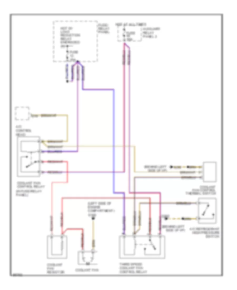
Электросхема системы охлаждения для Audi A6 1997
Электросхема системы охлаждения для Audi A6 1997 - Список элементов:
- (behind left side of i/p)
- (in fuse/relay panel)
- (left side of engine compartment)
- A/c control head
- A/c refrigerant high pressure switch
- Auxiliary relay panel 2
- Coolant fan
- Coolant fan control relay
- Coolant fan control thermal switch
- Coolant fan resistor
- D16
- Fuse 25a
- Fuse 60a
- Fuse/ relay panel
- G100
- G202
- Hot at all times
- Hot w/ load reduction relay energized (x)
- Third speed coolant fan control relay
СИСТЕМА ПЕРЕДАЧИ ДАННЫХ
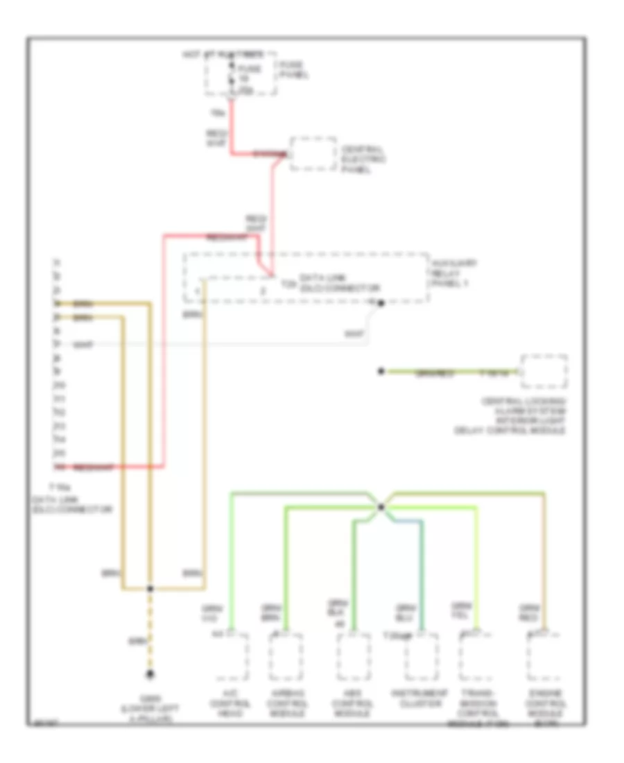
Электросхема линии передачи данных CAN для Audi A6 1997
Электросхема линии передачи данных CAN для Audi A6 1997 - Список элементов:
- 19a
- A/c control head
- Abs control module
- Airbag control module
- Auxiliary relay panel 1
- Central electric panel
- Central locking/ alarm system/ interior light delay control module
- Data link (dlc) connector
- Engine control module (ecm)
- Fuse 25a
- Fuse panel
- G900 (lower left a-pillar)
- Hot at all times
- Instrument cluster
- S1/30ah
- T16/14
- T16a
- T26a/4
- T2b
- Trans- mission control module (tcm)
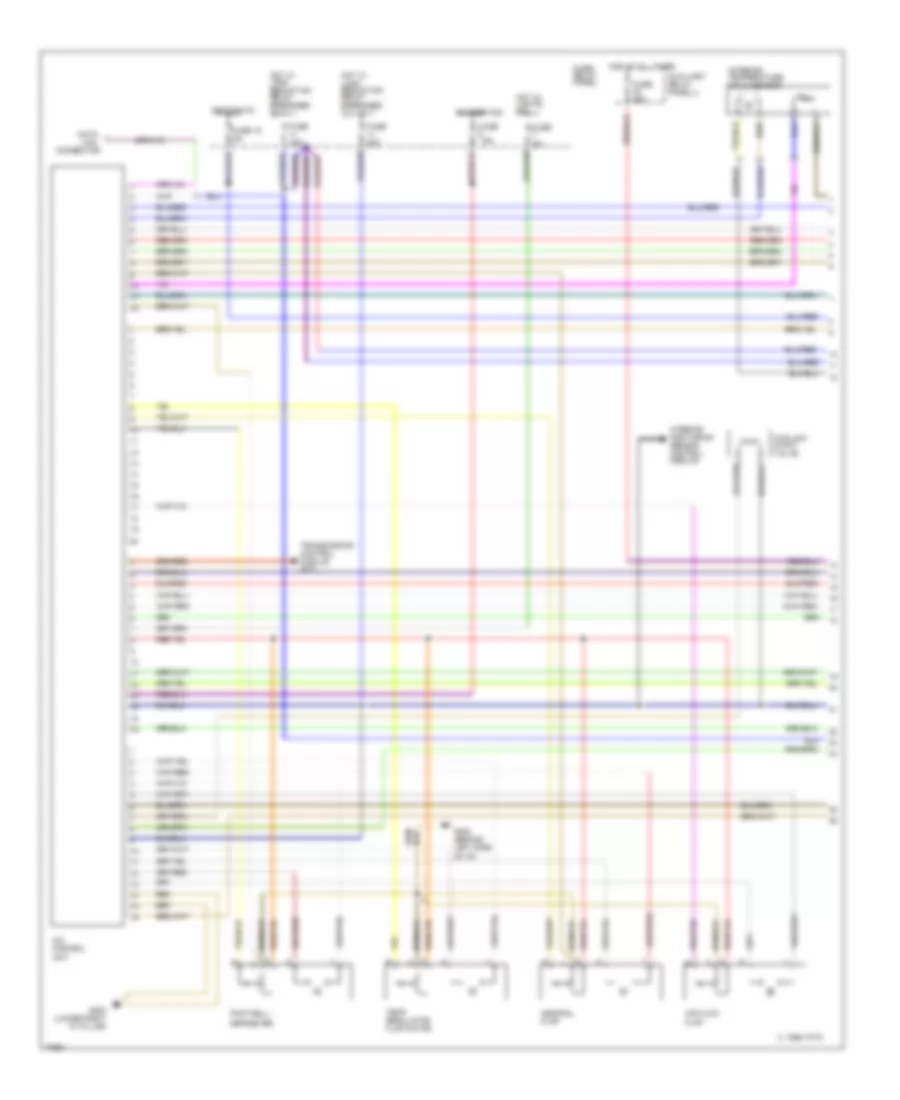
СИСТЕМА УПРАВЛЕНИЯ ДВИГАТЕЛЯ
2.8L
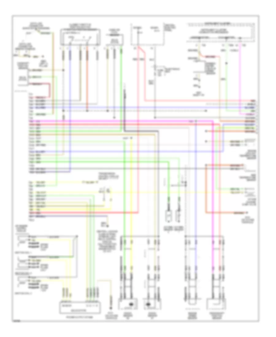
2.8L, Электросхема системы управления двигателем (1 из 2) для Audi A6 1997
2.8L, Электросхема системы управления двигателем (1 из 2) для Audi A6 1997 - Список элементов:
- (on intake manifold)
- (right i/p)
- (speedometer)
- (tachometer)
- A10
- A11
- A12
- A13
- A14
- A15
- A16
- A17
- A18
- A19
- A20
- A21
- A22
- A23
- A24
- B10
- B11
- B12
- Bat(30)
- Camshaft position sensor
- Central electric panel
- Central locking/ alarm system/ interior light delay control module, multi-function transmission range switch (w/ a/t)
- Closed throttle position switch/ throttle position sensor
- Crankshaft position sensor
- Data link connector (behind console)
- Data link connector (rapid data transfer)
- Egr temperature sensor
- Electronic box
- Engine coolant temperature sensor
- Engine speed sensor
- Fuse 15a
- G131
- G131 (on intake manifold)
- G201
- G900 (left a pillar)
- Ign (15)
- Ignition coil 1
- Ignition coil 2
- Ignition coil 3
- Instrument cluster
- Instrument cluster combination processor
- Intake change- over valve
- Knock sensor #1
- Knock sensor #2
- Mass air flow sensor
- Mfi engine control module
- Nca
- Oxygen sensor
- Power output stage
- Red
- Shield
- Solid state
- Spark plugs 1 & 6
- Spark plugs 2 & 4
- Spark plugs 3 & 5
- Speedo- meter vehicle speed sensor
- T26
- T26a
- Transmission control module (w/ a/t)
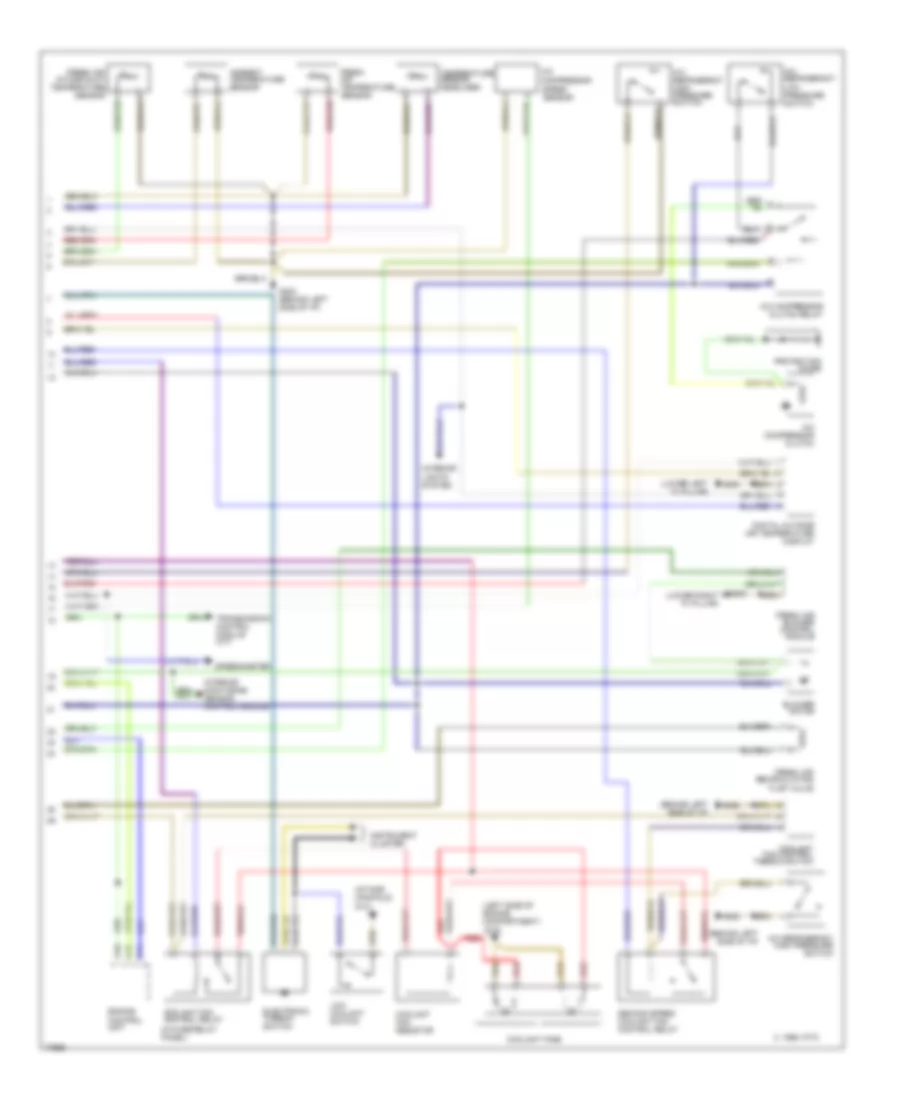
2.8L, Электросхема системы управления двигателем (2 из 2) для Audi A6 1997
2.8L, Электросхема системы управления двигателем (2 из 2) для Audi A6 1997 - Список элементов:
- 87f
- 87a
- A/c control head
- Abs control
- Auxiliary relay panel 3
- Bat(30)
- C1
- C10
- C11
- C12
- C13
- C14
- C15
- C16
- C17
- C18
- C19
- C20
- C21
- C22
- C23
- C24
- Central electric panel
- Computer display
- D10
- D11
- D12
- Dti
- E10
- E11
- E12
- Egr vacuum regulator solenoid valve
- Electronic box
- Evaporative emission canister purge regulator valve
- Evaporative emission canister purge solenoid valve
- Fuel injectors
- Fuel pump
- Fuel pump relay
- Fuel system diagnostic pump
- Fuse 10a
- Fuse 15a
- Fuse 20a
- Fuse 40a
- Fuse block
- G131 (on intake manifold)
- G201 (right i/p)
- G404 (left trunk)
- Hot in on or start
- Idle air control valve
- Ign(15)
- Mal- function indicator lamp (mil)
- Mfi engine control module
- Module
- Nca
- Oxygen sensor 1 heater
- Oxygen sensor 1 heater, b/h twc
- Oxygen sensor 1, b/h twc
- Oxygen sensor 2 heater
- Oxygen sensor 2 heater, b/h twc
- Oxygen sensor 2, b/h twc
- Red
- Secondary air injection pump motor
- Secondary air injection pump relay
- Secondary air injection solenoid valve
- Shield
- Transmission control module
- Unit
СИСТЕМА УСИЛИТЕЛЯ РУЛЯ
Электросхема усилителя руля для Audi A6 1997
Электросхема усилителя руля для Audi A6 1997 - Список элементов:
- (lower left "a" pillar)
- Acc
- Cluster
- G900
- Hot at all times
- Ignition switch
- Instrument
- Lock
- Servotronic
- Servotronic control unit
- Solenoid valve
- Speedo- meter
- Start
- T26/7
Система Фар
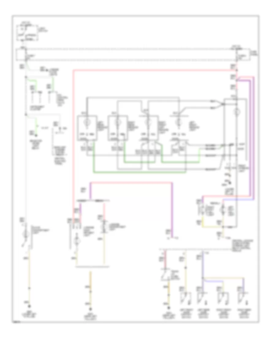
схема противотуманных фар, С DRL для Audi A6 1997
схема противотуманных фар, С DRL для Audi A6 1997 - Список элементов:
- (lower left "a" pillar)
- (lower right "a" pillar)
- (near left taillight)
- 75x
- Acc
- All times
- Auxiliary relay panel 1
- Central electric panel
- Daytime running lights change- over relay
- Daytime running lights switch- on relay
- Fog light relay (#4)
- Fog light switch
- Ftp
- Fuse 1 10a
- Fuse 15a
- Fuse 2 10a
- Fuse panel
- G404
- G900
- G901
- Head
- Head/park light switch
- Headlight dimmer switch
- Headlight system washer relay
- Hi beam ind
- Hot at
- Hot in acc
- Ignition switch
- Instrument cluster
- Interior lights system
- Left front fog light
- Left head- light
- Light switch
- Load reduction relay
- Off
- Or run
- Park
- Rear fog light
- Rear fog light switch
- Rear window defogger switch
- Red
- Right front fog light
- Right head- light
- Run
- Start
Электросхема фар и противотуманок, без DRL для Audi A6 1997
Электросхема фар и противотуманок, без DRL для Audi A6 1997 - Список элементов:
- (lower left "a" pillar)
- (lower right "a" pillar)
- (near left taillight)
- 56a
- 56b
- Acc
- Auto- check system
- Auxiliary relay panel 1
- Central electric panel
- Cluster
- Exterior lights system
- Fog light relay (#4)
- Fog light switch
- Ftp
- Fuse 10a
- Fuse 15a
- Fuse panel
- G404
- G900
- G901
- Head
- Head/park light switch
- Headlight dimmer switch
- Hi beam ind.
- Hot at all times
- Ignition switch
- Instrument
- Instrument cluster
- Interior lights system
- Lamp control module
- Left front fog light
- Left head- light
- Light switch
- Load reduction relay
- Off
- Park
- Rear fog light
- Rear fog light switch
- Red
- Right front fog light
- Right head- light
- Run
- Start
- T14
- T26
- T26a
Электросхема фар, С DRL для Audi A6 1997
Электросхема фар, С DRL для Audi A6 1997 - Список элементов:
- (lower left "a" pillar)
- (lower right "a" pillar)
- (near left taillight)
- Acc
- Auxiliary relay panel 1
- Brake light switch
- Central electric panel
- Daytime running lights change- over relay
- Daytime running lights switch- on relay (#7)
- Fog light relay
- Ftp
- Fuse 10a
- Fuse 5a
- Fuse panel
- G404
- G900
- G901
- Head
- Head/park light switch
- Headlight dimmer switch
- Headlight system washer relay
- Hi beam ind.
- Hot at all times
- Ignition switch
- Instrument cluster
- Lamp control module
- Left front park light
- Left head- light
- Left tail/ stop light
- License plate lamps
- Light switch
- Load reduction relay
- Off
- Park
- Red
- Right front park light
- Right head- light
- Right tail/ stop light
- Run
- Series resistance wiring
- Start
- Stop
- T26
- T26a
- Tail
СИСТЕМЫ ПАМЯТИ
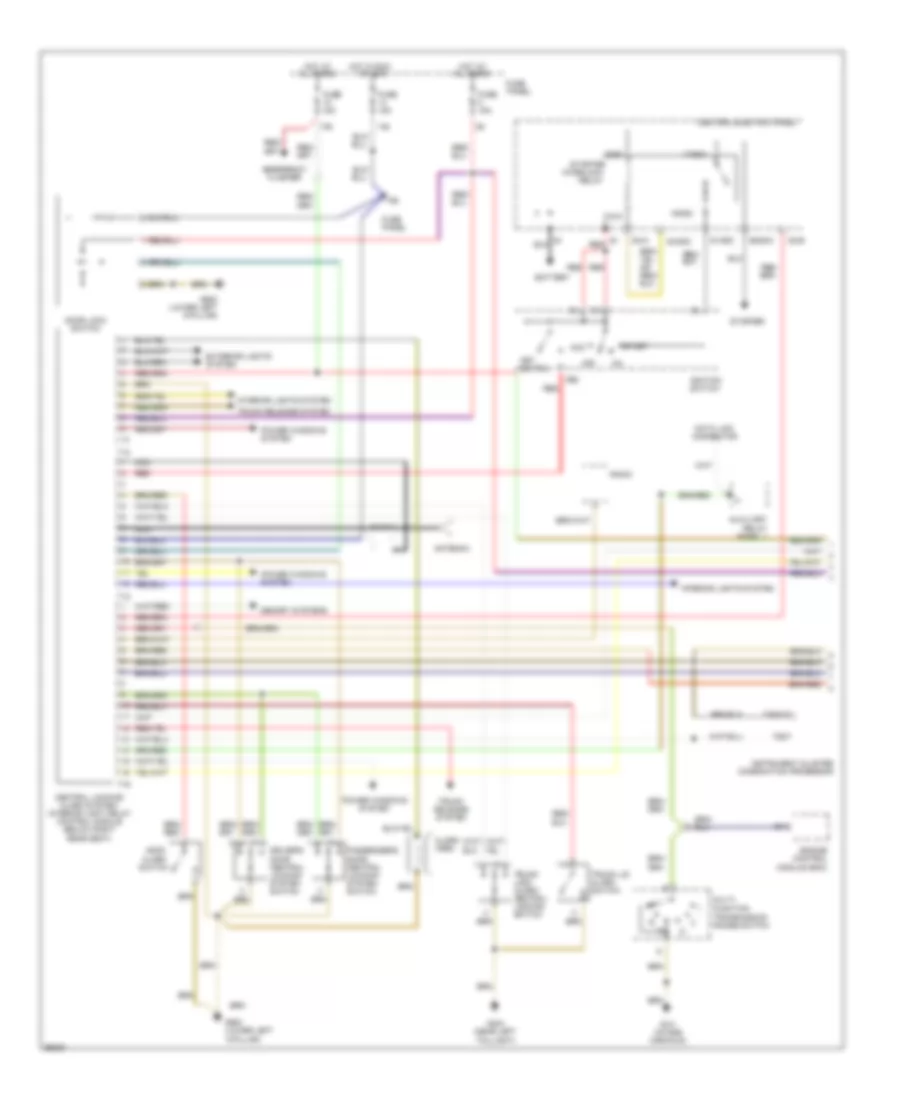
Электросхема системы памяти (1 из 2) для Audi A6 1997
Электросхема системы памяти (1 из 2) для Audi A6 1997 - Список элементов:
- Auxiliary relay panel 1
- Back- rest
- Central locking/ alarm system/ interior light delay control module
- Circuit breaker 44 30a
- Driver seat backrest adjusting motor
- Driver seat fore/ aft adjusting motor
- Driver seat front height adjusting motor
- Driver seat rear height adjusting motor
- Driver seat switch
- Fore/ aft
- Front height
- G900 (lower left "a" pillar)
- Hot at all times
- Left front door contact switch
- Memory program switch
- Memory seat control module
- Rear height
- Red
- T16
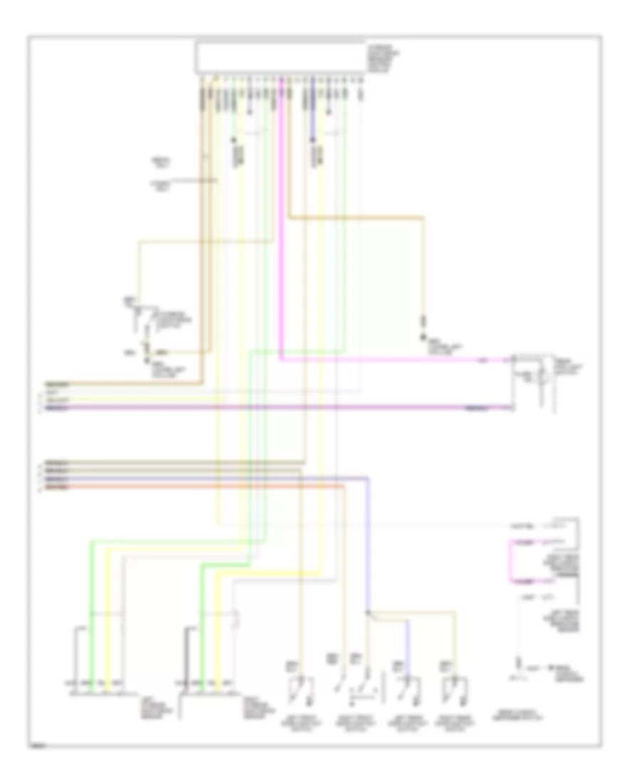
Электросхема системы памяти (2 из 2) для Audi A6 1997
Электросхема системы памяти (2 из 2) для Audi A6 1997 - Список элементов:
- A10
- B10
- Back-up lights
- De- fog
- Driver side mirror
- Fold- away
- Fuse 14 15a
- Fuse 15 5a
- Fuse 8 15a
- Fuse panel
- G900 (lower left "a" pillar)
- Hot at all times
- Hot in run
- Hot in run or start
- Memory mirror control module
- Mirror adjustment switch
- Mirror fold-away control module
- Mirror position
- Mirror select
- Or start
- Passenger side mirror
- Position
- Red
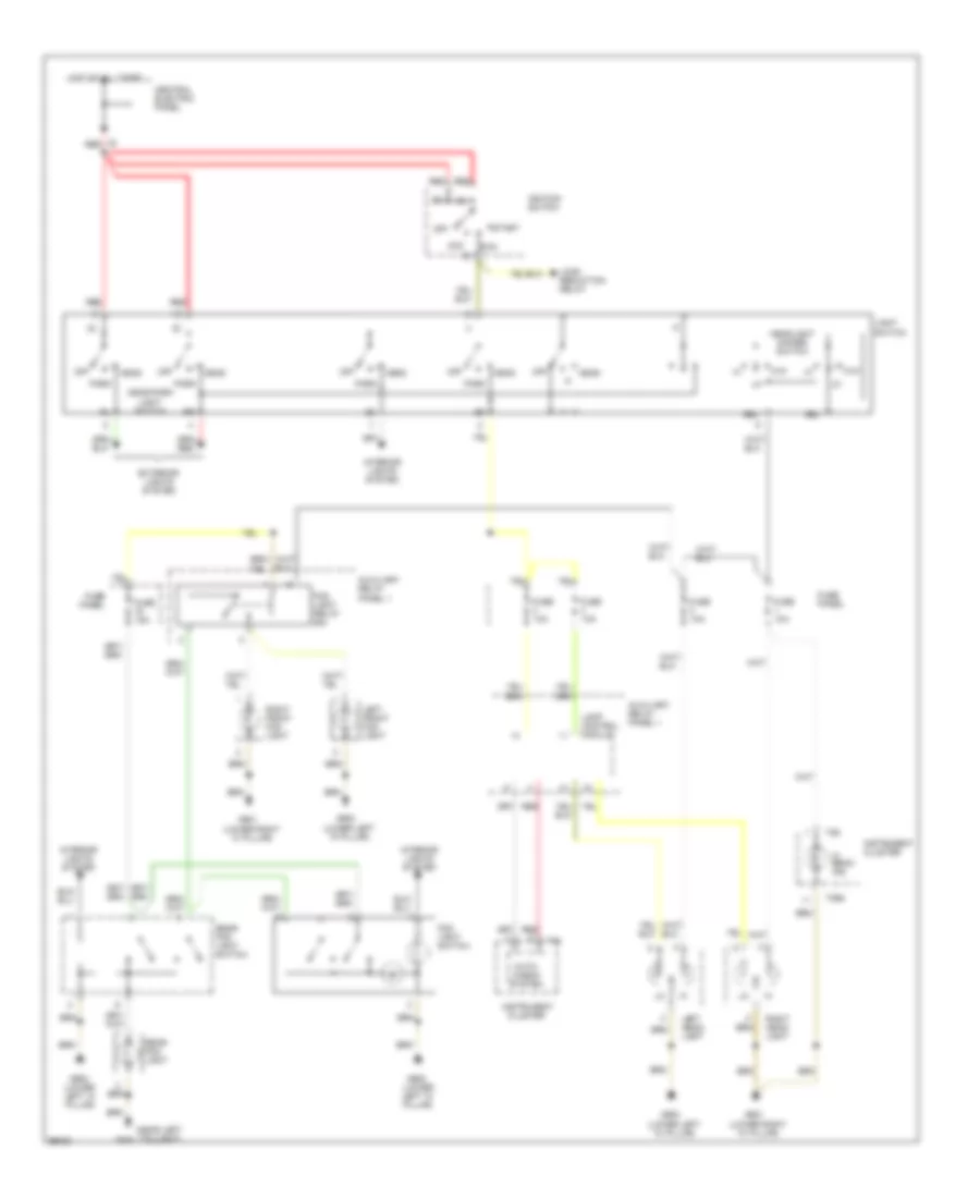
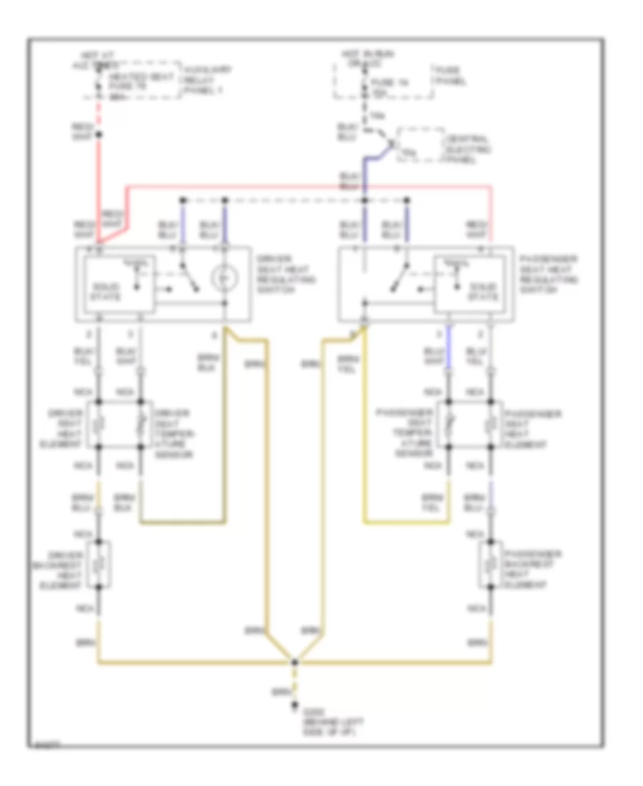
СИСТЕМЫ СИДЕНИЙ
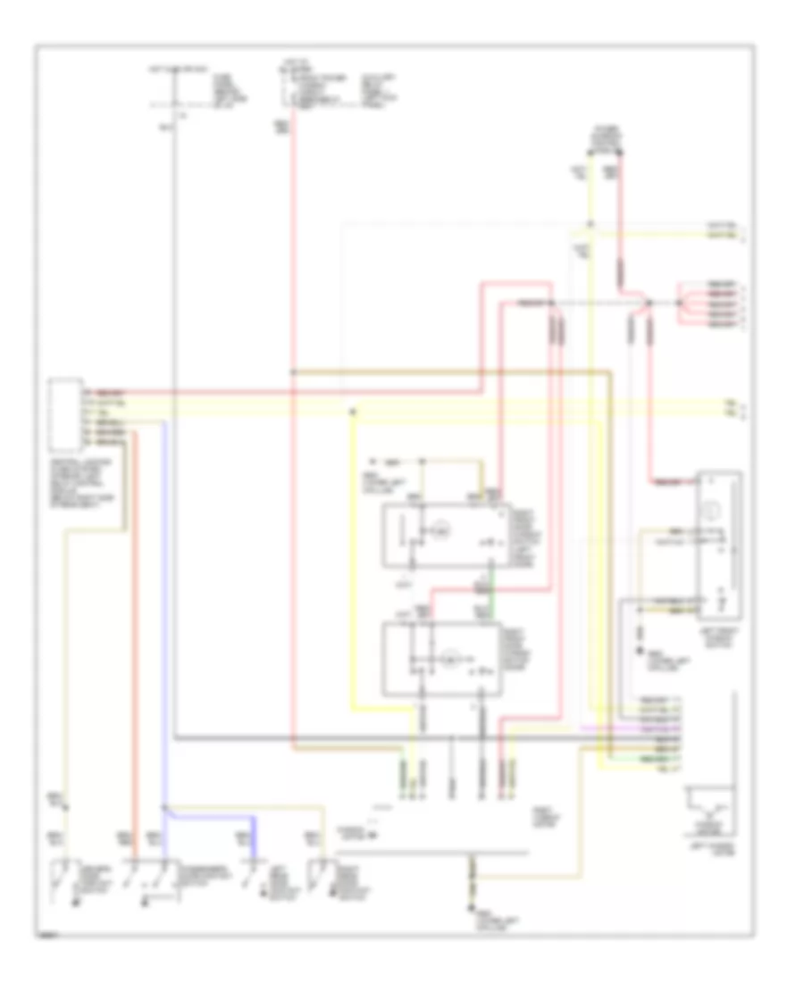
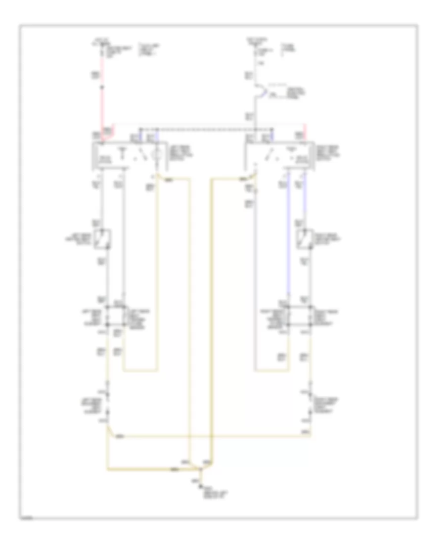
Электросхема подогрева передних сидений для Audi A6 1997
Электросхема подогрева передних сидений для Audi A6 1997 - Список элементов:
- 14a
- 15a
- All times
- Auxiliary relay panel 1
- Central electric panel
- Driver backrest heat element
- Driver seat heat element
- Driver seat heat regulating switch
- Driver seat temper- ature sensor
- Fuse 14 15a
- Fuse panel
- G202 (behind left side of i/p)
- Heated seat fuse 79 30a
- Hot at
- Hot in run or acc
- Nca
- Passenger backrest heat element
- Passenger seat heat element
- Passenger seat heat regulating switch
- Passenger seat temper- ature sensor
- Solid state
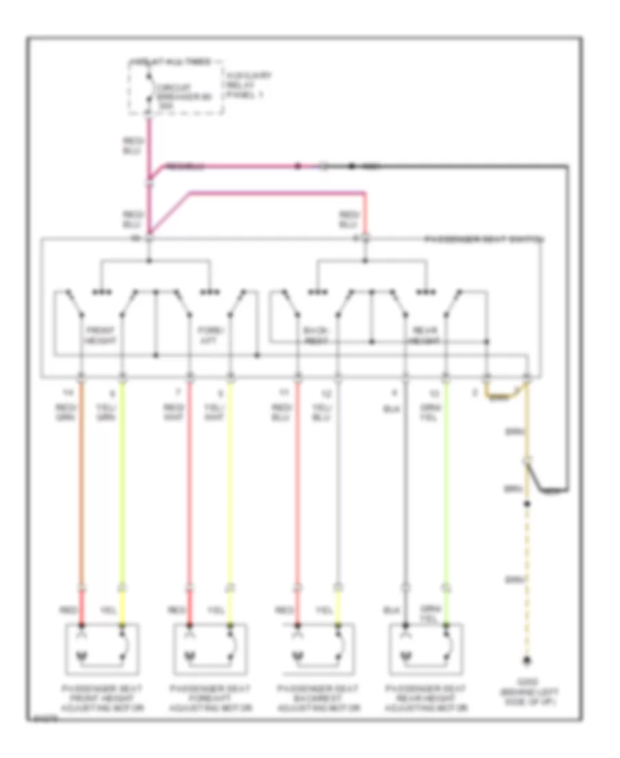
схема сиденья пассажира для Audi A6 1997
схема сиденья пассажира для Audi A6 1997 - Список элементов:
- Auxiliary relay panel 1
- Back- rest
- Circuit breaker 80 30a
- Fore/ aft
- Front height
- G202 (behind left side of i/p)
- Hot at all times
- Nca
- Passenger seat backrest adjusting motor
- Passenger seat fore/aft adjusting motor
- Passenger seat front height adjusting motor
- Passenger seat rear height adjusting motor
- Passenger seat switch
- Rear height
- Red
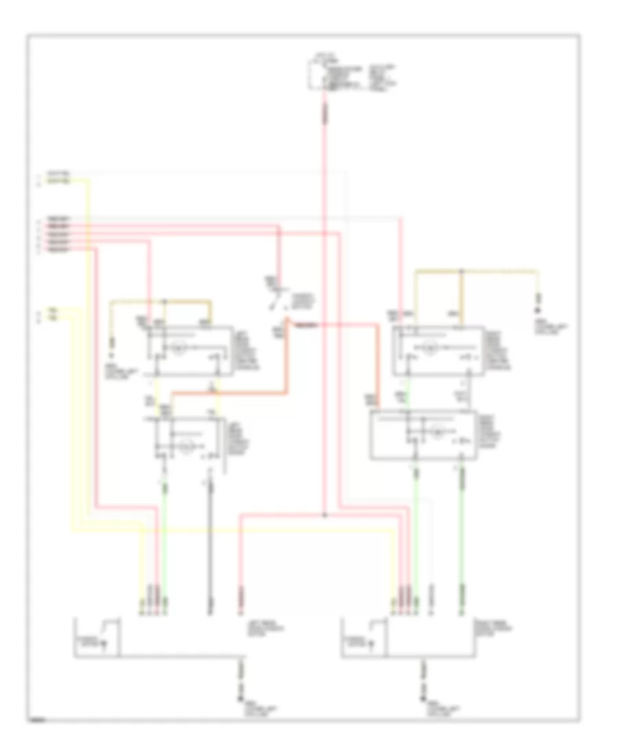
Электросхема подогрева задних сидений для Audi A6 1997
Электросхема подогрева задних сидений для Audi A6 1997 - Список элементов:
- 14a
- 15a
- All times
- Auxiliary relay panel 1
- Central electric panel
- Fuse 14 15a
- Fuse panel
- G202 (behind left side of i/p)
- Heated seat fuse 79 30a
- Hot at
- Hot in run or acc
- Left rear backrest heat element
- Left rear heated seat switch
- Left rear seat heat element
- Left rear seat heat regulating switch
- Left rear seat temper- ature sensor
- Nca
- Right rear backrest heat element
- Right rear heated seat switch
- Right rear seat heat element
- Right rear seat heat regulating switch
- Right rear seat temper- ature sensor
- Solid state
Стартер Генератор
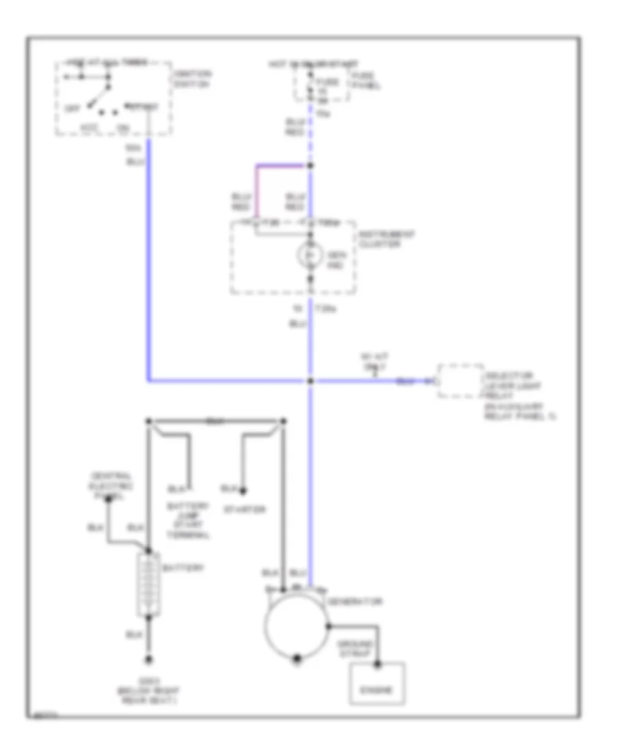
Электросхема Генератора для Audi A6 1997
Электросхема Генератора для Audi A6 1997 - Список элементов:
- (in auxiliary relay panel 1)
- 15a
- 50b
- Acc
- Battery
- Battery jump start terminal
- Central electric
- Engine
- Fuse 5a
- Fuse panel
- G303 (below right rear seat)
- Gen ind.
- Generator
- Ground strap
- Hot at all times
- Hot in on or start
- Ignition switch
- Instrument cluster
- Off
- Panel
- Selector lever light relay
- Start
- Starter
- T26
- T26a
- W/ a/t only
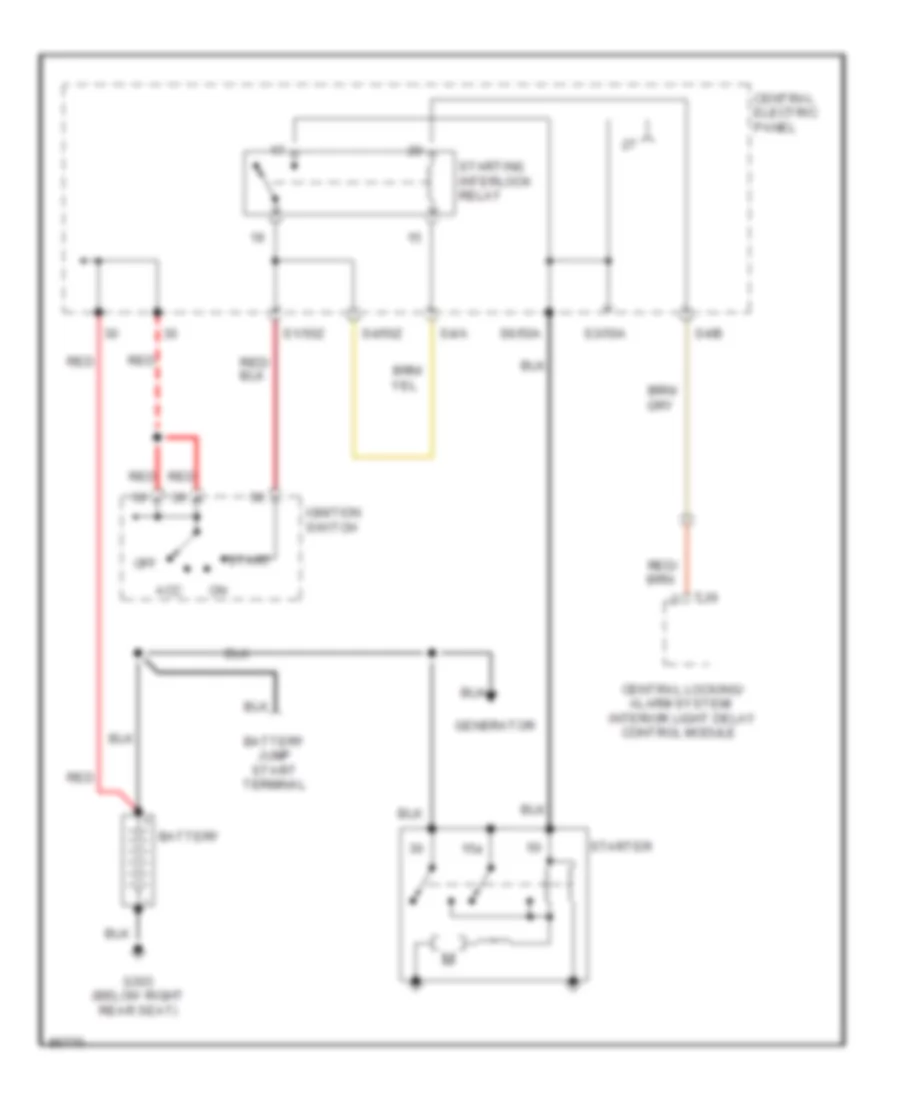
Электросхема стартера для Audi A6 1997
Электросхема стартера для Audi A6 1997 - Список элементов:
- 15a
- Acc
- Alarm system/
- Battery
- Battery jump start terminal
- Central electric panel
- Central locking/
- Control module
- G303 (below right rear seat)
- Generator
- Ignition switch
- Interior light delay
- Off
- Red
- S1/50z
- S3/50a
- S4/50z
- S4/a
- S4/b
- S6/50a
- Start
- Starter
- Starting interlock relay
- T16
Стеклоочистители и Стеклоомыватели Дворники
Электросхема стеклоочистителя, дворников и омывателя для Audi A6 1997
Электросхема стеклоочистителя, дворников и омывателя для Audi A6 1997 - Список элементов:
- 58a
- 75a
- Auxiliary relay panel 1
- Battery
- Central electric panel
- Fuse 15a
- Fuse 25a
- Fuse 5a
- Fuse panel
- G100 (left side of engine compt)
- G202 (left side of i/p)
- G404 (near left taillight)
- G900 (lower left "a" pillar)
- Headlight washer pump
- Headlight washer system relay
- Headlights on
- Hot in on
- Hot in on or start
- Hot w/ park or
- Instrument cluster system
- Left washer nozzle heater
- Or acc
- Rear window washer pump
- Rear window wiper motor
- Rear window wiper/ washer relay
- Right washer nozzle heater
- S1/31
- S2/ 53e
- S2/31b
- S2/53c
- S2/j
- S5/p
- Solid state
- Station wagon only
- Washer fluid level switch
- Washer switch
- Windshield washer pump
- Windshield wiper motor
- Windshield wiper/ washer switch
- Wiper switch
- Wiper/ washer inter- mittent relay
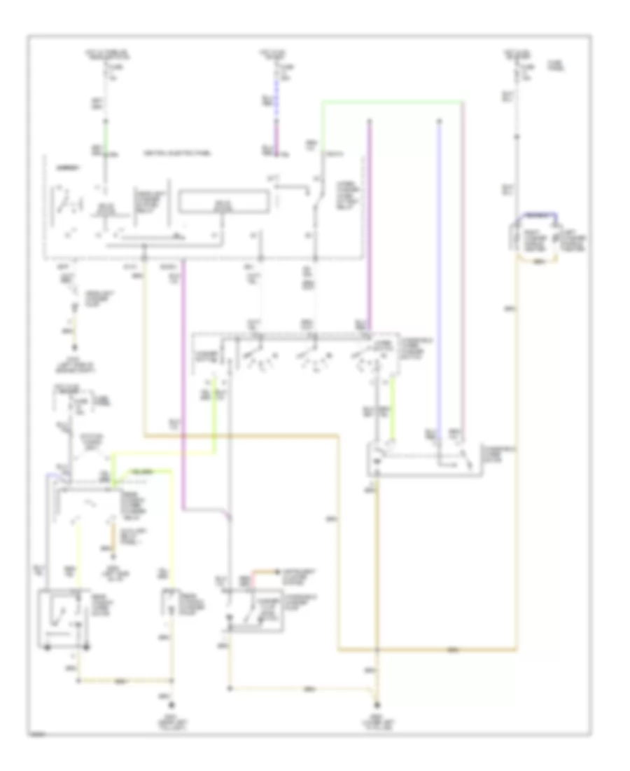
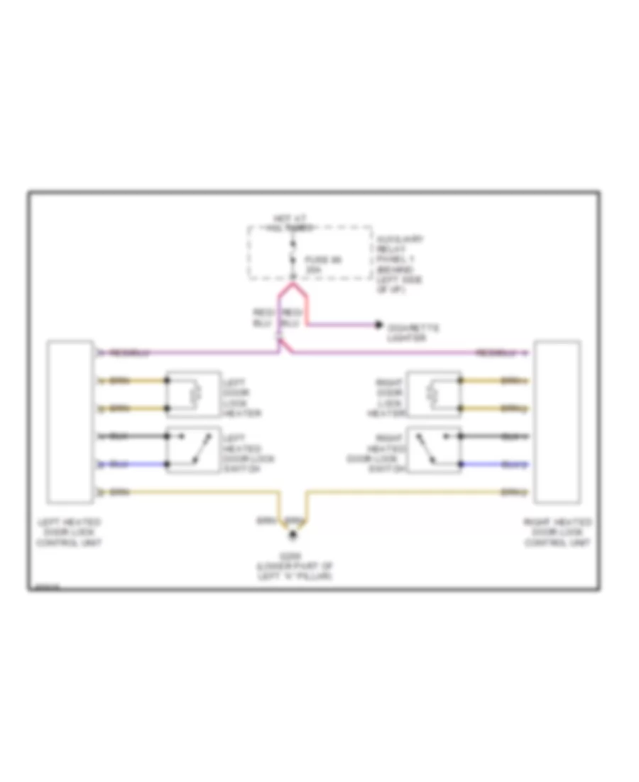
ЦЕНТРАЛЬНЫЙ ЗАМОК
горячая дверь захватывает схему для Audi A6 1997
горячая дверь захватывает схему для Audi A6 1997 - Список элементов:
- All times
- Auxiliary relay panel 1 (behind left side of i/p)
- Cigarette lighter
- Door lock
- Fuse 86 20a
- G200 (lower part of left "a" pillar)
- Heated
- Heater
- Hot at
- Left door lock heater
- Left heated door lock control unit
- Left heated door lock switch
- Right
- Right door lock
- Right heated door lock control unit
- Switch

 Čeština
 Dansk
Dansk Deutsch
 Ελληνικά
 English
 English
 Español
 Français
 Français
 עברית
עברית Hrvatski
 Magyar
 Italiano
 日本語
日本語 한국어
한국어 Nederlands
 Polski
 Português
 Português
 Română
 Русский
 Slovenčina
 Slovenščina
 Svenska
 Türkçe
 中文 (中国)