TRANSMISSION
Transfer Case Wiring Diagram for Isuzu Ascender LS 2005
 https://portal-diagnostov.com/license.html
Automotive Electricians Portal FZCO
Automotive Electricians Portal FZCO
https://portal-diagnostov.com/license.html
https://portal-diagnostov.com/license.html
Automotive Electricians Portal FZCO
Automotive Electricians Portal FZCO
List of elements for Transfer Case Wiring Diagram for Isuzu Ascender LS 2005:
- (below dash, above accelerator pedal) data link connector
- (on lower left side of engine)
- +5v ref
- 2wd
- 2wd ind
- 4 hi
- 4 hi ind
- 4 lo
- 4 lo ind
- 4.2l
- 4wd fuse 48 15a
- 4wd lo sig
- 5.3l
- Afwd
- Afwd ind
- Atc fuse 8 30a
- Axle act
- Axle sw
- B11
- Battery
- Brake
- C2 a11
- Class 2 data
- E11
- E5 c3
- Encoder
- Encoder sig
- Front axle actuator (lower right front of engine, on oil pan)
- Front sig hi
- Front sig lo
- Front transfer case propshaft speed sensor (on left rear of transfer case)
- G102 (at left side of engine compt)
- G107
- G201
- Ground
- Hot at all times
- Hot in run
- Hot in run or start
- Illum
- Ing e fuse 22 10a
- Instrument panel cluster (ipc)
- Interior lights system
- Lock sol
- Logic
- Low ref
- Motor
- Motor ctrl a
- Motor ctrl b
- Neut
- Neutral
- Neutral ind
- Pnk
- Powertrain control module (4.2l) (on left front of engine) engine control module (5.3l) (on left front of engine compt)
- Rear fuse block (below left rear seat)
- Rear sig hi
- Rear sig lo
- Rear transfer case propshaft speed sensor (on right rear of transfer case)
- Red
- Service 4wd
- Sp201 (lower right center of dash)
- Splice pack sp205 (below left side of i/p)
- Sw sig
- Tan
- Transfer case
- Transfer case shift control module (behind left lower dash)
- Transfer case shift control switch
- Under- hood fuse block (on left side of engine compt)
- Underhood fuse block (on left side of engine compt)
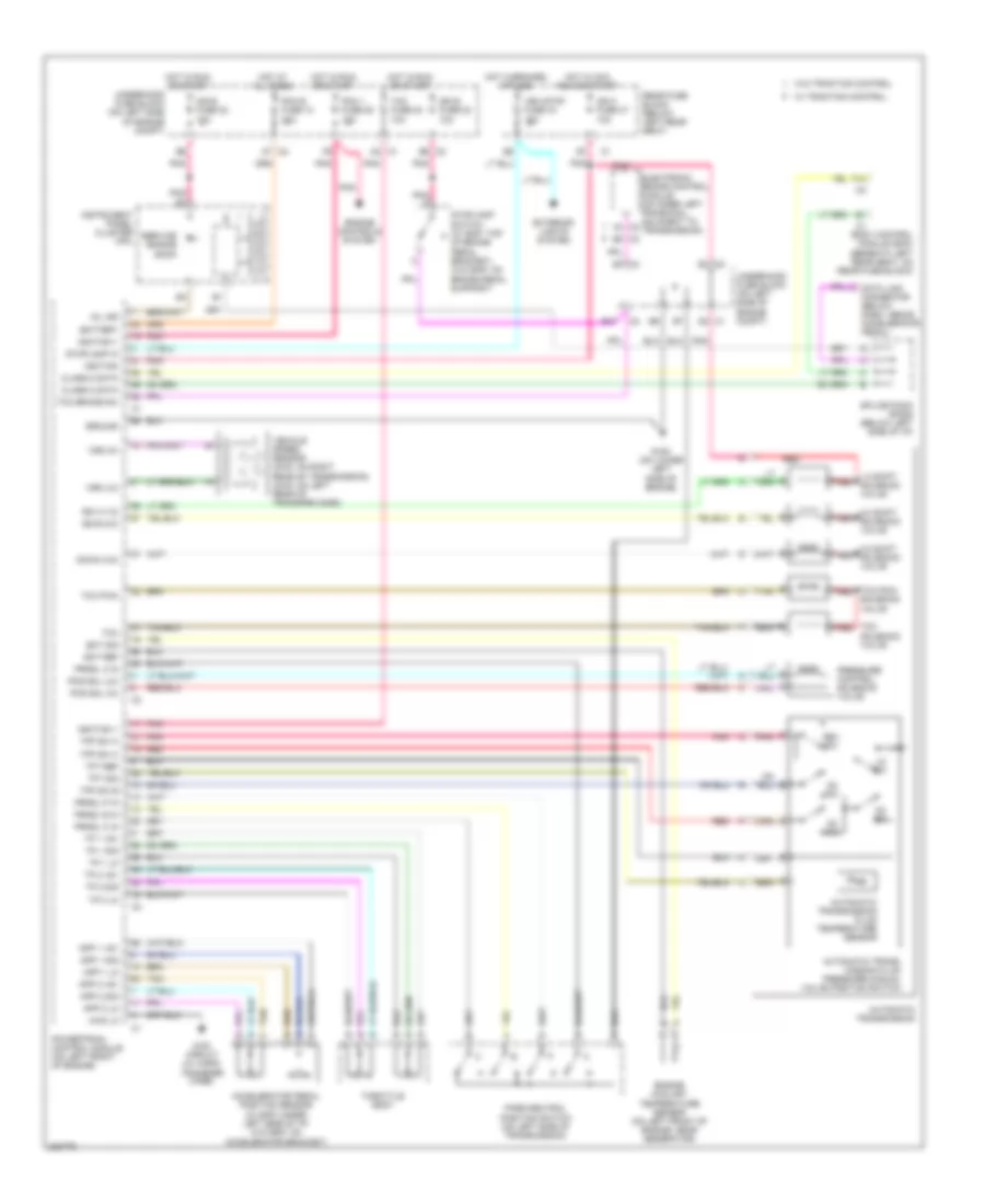
4.2L
4.2L, A/T Wiring Diagram for Isuzu Ascender LS 2005
List of elements for 4.2L, A/T Wiring Diagram for Isuzu Ascender LS 2005:
- 1-2 shift red solenoid valve
- 2-3 shift red solenoid valve
- 3-2 shift red solenoid valve
- 4wd circuit (w/ 2-spd transfer case)
- 4wd lo
- A2 c1
- A3 c2
- Accelerator pedal position sensor (w/ eap: under left side of i/p) (w/o eap: on accelerator bracket)
- App 1 +5v
- App 1 lo
- App 1 sig
- App 2 +5v
- App 2 lo
- App 2 sig
- Automatic trans- mission fluid pressure manual valve position switch
- Automatic transmission
- Automatic transmission fluid temperature sensor
- B10
- B5 c2
- B6 c2
- Battery
- Body control module (bcm) (beneath left rear seat, on rear fuse block)
- C2 a7
- Class 2 data
- D2 c1
- D2 sw
- D3 sw
- D4 sw
- Data link connector (below dash, above accelerator pedal)
- Down (3-2)
- E3 c2
- E3 c3
- Ect ref
- Ect sig
- Electronic brake control module (on inner left frame rail, adjacent to transmission)
- Engine controls system
- Engine coolant temperature sensor (on left front of engine, near generator)
- Exterior lights system
- F14
- G108 (on lower left side of engine)
- Ground
- Hot at all times
- Hot in acc, run or start
- Hot in run or start
- Ign 0 fuse 47 10a
- Ign e fuse 22 10a
- Ignition
- Ignition 1
- Ing e fuse 22 10a
- Instrument panel cluster (ipc)
- Lo sw
- Mil ind
- P r n d
- Park/neutral position switch (on left side of transmission)
- Pcm 1 fuse 28 15a
- Pcm b fuse 10 20a
- Pcs sol (hi)
- Pcs sol (lo)
- Pnk
- Pnk d
- Powertrain control module (on left front of engine)
- Pressure control solenoid valve
- Prndl a in
- Prndl b in
- Prndl c in
- Prndl p in
- Rear fuse block (below left rear seat)
- Red
- Rev sw
- Service engine soon
- Solenoid valve
- Splice pack sp205 (below left side of i/p)
- Ss a (1-2)
- Ss b (2-3)
- Stoplamp in
- Stoplamp switch (w/ eap: top of brake pedal bracket) (w/o eap: on brake pedal support)
- Tac fuse 23 10a
- Tan
- Tcc
- Tcc brake sw
- Tcc pmw red
- Tcc pwm
- Tcc red
- Tfp sw a
- Tfp sw b
- Tfp sw c
- Tft ref
- Tft sig
- Throttle body
- Tp 1 +5v
- Tp 1 lo
- Tp 1 sig
- Tp 2 +5v
- Tp 2 lo
- Tp 2 sig
- Underhood fuse block (on left side of engine compt)
- Veh stop fuse 34 15a
- Vehicle speed sensor (2wd: on right rear of transmission) (4wd: on left rear of transfer case)
- Vss (hi)
- Vss (lo)
- W/ traction control
- W/o traction control
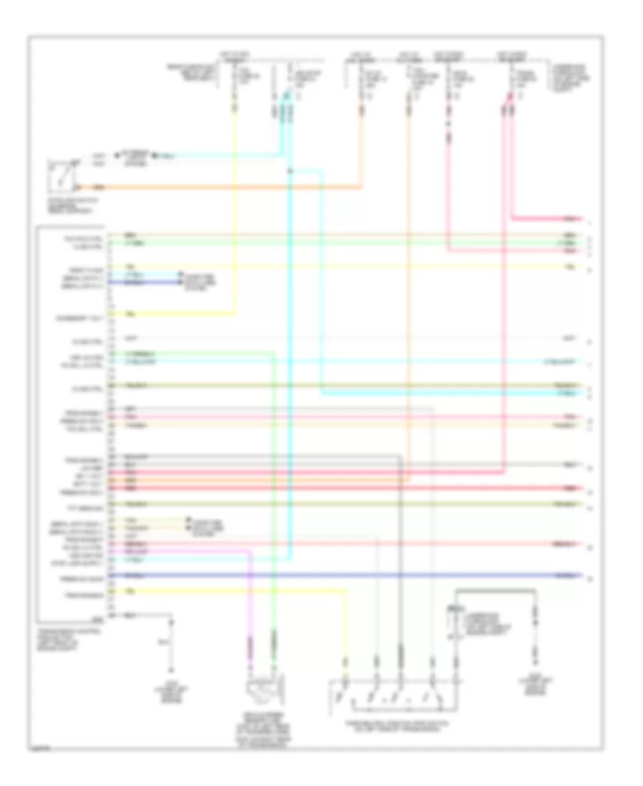
5.3L
5.3L, A/T Wiring Diagram (1 of 2) for Isuzu Ascender LS 2005
List of elements for 5.3L, A/T Wiring Diagram (1 of 2) for Isuzu Ascender LS 2005:
- (2wd: on right rear of transmission)
- 1-2 ss ctrl
- 2-3 ss ctrl
- 3-2 ss ctrl
- Accessory volt
- B11
- Batt volt
- Computer data lines system
- Exterior lights system
- Front hi sig
- G108 (lower left side of engine)
- Gnd
- Hot at all times
- Hot in acc or run
- Hot in run or start
- Ign 1 volt
- Ign e fuse 22 10a
- Low ref
- Park/neutral position (pnp) switch (on left side of transmission)
- Pc sol hi ctrl
- Pc sol lo ctrl
- Pnk
- Pnk pnk
- Press sw sig a
- Press sw sig b
- Press sw sig c
- Rear fuse block (below left rear seat)
- Red
- Serial data (+)
- Serial data (-)
- Serial data bus (+)
- Serial data bus (-)
- St/lp fuse 12 25a
- Stoplamp switch (on brake pedal support)
- Tan
- Tcc pwm ctrl
- Tcc sol ctrl
- Tcm fuse 35 10a
- Tcm/ canister fuse 15 10a
- Tft sens sig
- Trans fuse 53 15a
- Transmission control module (tcm) (left front of engine compt)
- Trns range a
- Trns range b
- Trns range c
- Trns range p
- Underhood fuse block (on left side of engine compt)
- Underhood fuse block (on left side of engine compt) c1
- Veh stop fuse 34 15a
- Vehicle speed sensor (vss) (4wd: on left rear of transfer case)
- Vss high sig
- Vss low sig
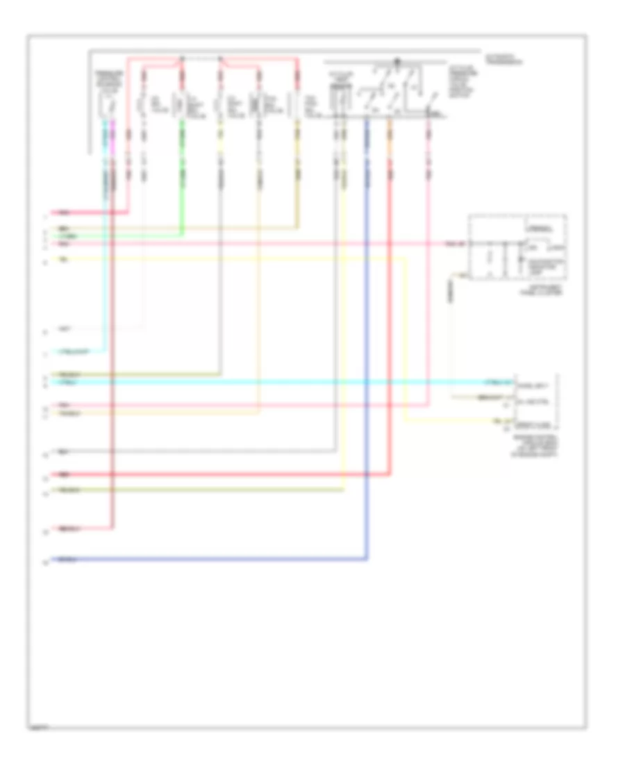
5.3L, A/T Wiring Diagram (2 of 2) for Isuzu Ascender LS 2005
List of elements for 5.3L, A/T Wiring Diagram (2 of 2) for Isuzu Ascender LS 2005:
- 1-2 shift sol valve
- 2-3 shift sol valve
- 3-2 sol valve
- A/t fluid pressure manual valve position switch
- A/t fluid temp sensor
- Automatic transmission
- Chmsl sply
- Engine control module (ecm) (on left front of engine compt)
- Front hi sig
- Ign
- Instrument panel cluster
- Logic
- Malfunction indicator lamp
- Mil ind ctrl
- Pnk
- Pressure control solenoid valve
- Prnd321
- Red
- Rev
- Tan
- Tcc pwm sol valve
- Tcc sol valve

 Čeština
 Dansk
Dansk Deutsch
 Ελληνικά
 English
 English
 Español
 Suomi
Suomi Français
 עברית
עברית Hrvatski
 Magyar
 Italiano
 日本語
日本語 한국어
한국어 Nederlands
 Polski
 Português
 Português
 Română
 Русский
 Slovenčina
 Slovenščina
 Svenska
 Türkçe
 中文 (中国)