AIR CONDITIONING
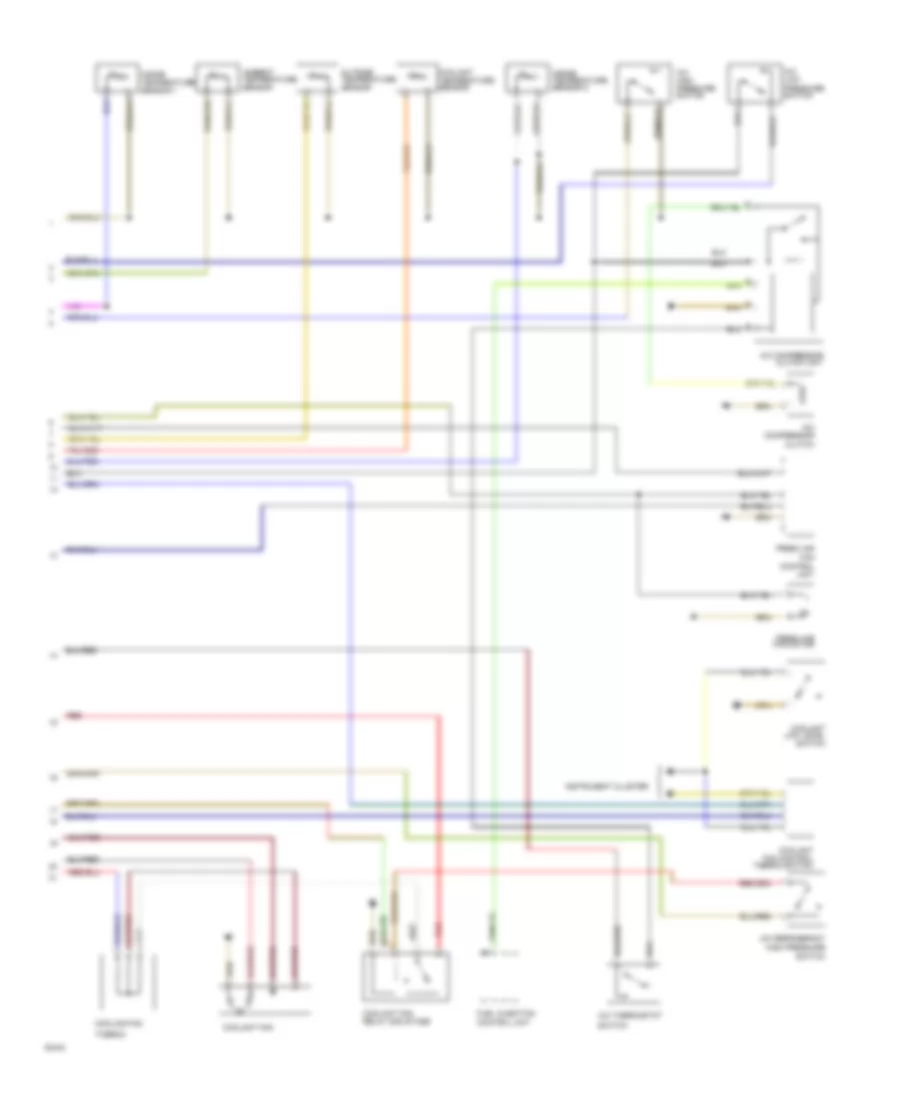
Automatic A/C Wiring Diagram (1 of 2) for Audi 100 1991
 https://portal-diagnostov.com/license.html
Automotive Electricians Portal FZCO
Automotive Electricians Portal FZCO
https://portal-diagnostov.com/license.html
https://portal-diagnostov.com/license.html
Automotive Electricians Portal FZCO
Automotive Electricians Portal FZCO
List of elements for Automatic A/C Wiring Diagram (1 of 2) for Audi 100 1991:
- (not used)
- 15a
- A/c control head
- A/c programmer
- Alternator
- Battery
- Coolant fan after run thermo switch
- Coolant fan relay-3rd stage
- Cooling fan after run control unit
- Cooling fan thermo switch
- Fuse
- Fuse 15a
- Fuse 25a
- Fuse 30a
- Fuse 5a
- Fuse/ relay panel
- Hot w/ lights on
- Hot w/ load reduction relay energized
- Ignition (15)
- Instrument cluster
- Interior temperature sensor 1 fan
- Red
- Tcm
- Temp regulator flap motor
Automatic A/C Wiring Diagram (2 of 2) for Audi 100 1991
List of elements for Automatic A/C Wiring Diagram (2 of 2) for Audi 100 1991:
- A/c compressor
- A/c compressor clutch unit
- A/c high pressure switch
- A/c low pressure switch
- A/c refrigerant high pressure
- A/c thermostat
- Ambient temperature sensor
- Clutch
- Control unit
- Coolant fan
- Coolant fan control thermo switch
- Coolant fan relay 2nd stage
- Coolant low level switch
- Coolant temperature sensor
- Cooling fan
- Fan
- Fresh air
- Fresh air fan motor
- Fuel injection control unit
- Inside temperature sensor 1
- Inside temperature sensor 2
- Instrument cluster
- Outside temperature sensor
- Red
- Switch
- Thermo

 Čeština
 Dansk
Dansk Deutsch
 Ελληνικά
 English
 English
 Español
 Suomi
Suomi Français
 עברית
עברית Hrvatski
 Magyar
 Italiano
 日本語
日本語 한국어
한국어 Nederlands
 Polski
 Português
 Português
 Română
 Русский
 Slovenčina
 Slovenščina
 Svenska
 Türkçe
 中文 (中国)