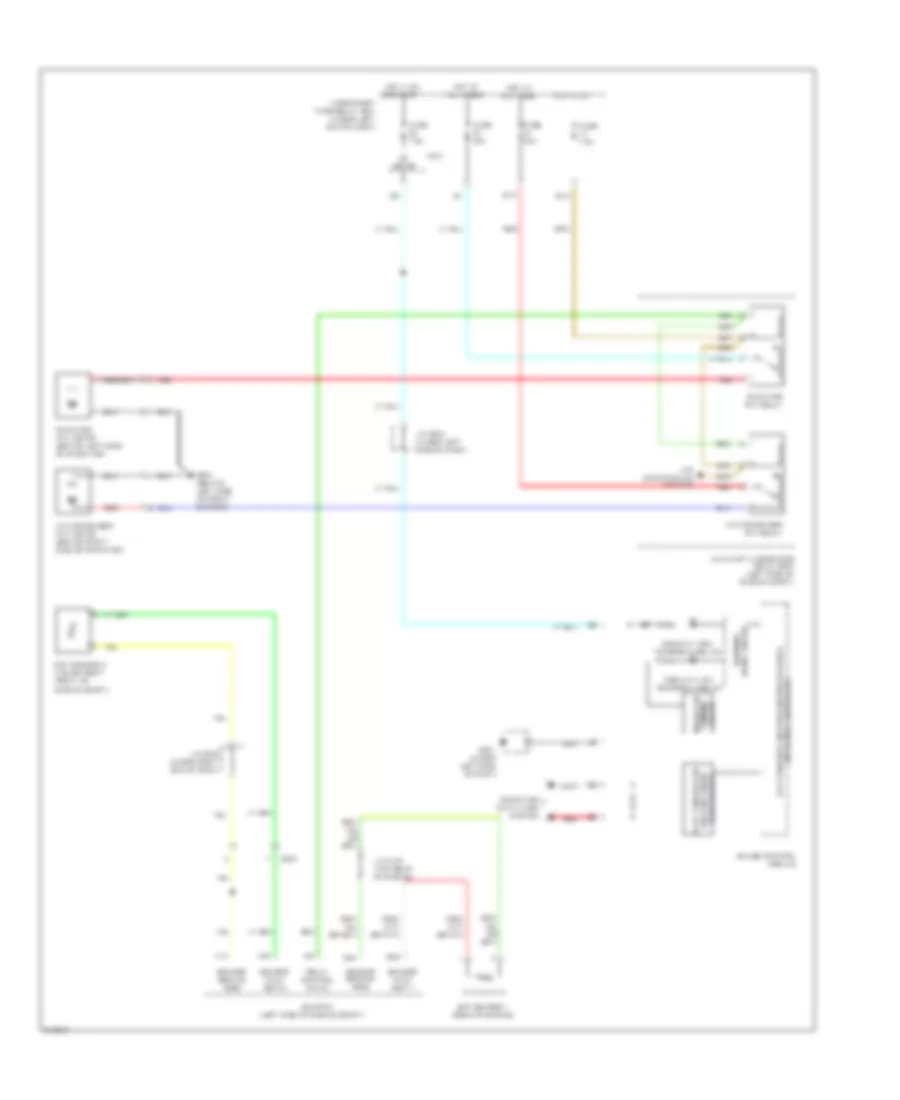
COOLING FAN
Cooling Fan Wiring Diagram for Honda Fit 2011
List of elements for Cooling Fan Wiring Diagram for Honda Fit 2011:
- (left side of engine compt)
- 5v stabilizer circuit/controller area
- A/c condenser fan motor (behind right side of radiator)
- A/c condenser fan relay
- A10
- A34
- Air conditioning system
- Auxiliary under-hood relay box (left side of engine compt)
- B12
- B15
- B24
- B34
- C203
- Computer data lines system
- Coolant high temperature ind
- Coolant low temperature ind
- Drive circuit warning
- Ecm/pcm
- Ect sensor 1 (rear of engine)
- Ect sensor 2 (lower right front of
- Engine compt)
- Fuse 30a
- Fuse 7.5a
- G301 (behind left side of front bumper)
- G501 (under left side of dash)
- Gauge control module
- Hot at all times
- Hot in on
- Hot in on or start
- Ig1 meter
- Indicator dimming circuit
- J/c c103 (top rear of engine)
- J/c c205 (under right end of dash)
- J/c c504 (under left side of dash)
- Micu
- Network controller
- Radiator fan motor (behind left side of radiator)
- Radiator fan relay
- Red
- Relay control (fanc)
- Sensor ground (sg2)
- Sensor ground (sg6)
- Sensor input (ect1)
- Sensor input (ect2)
- Transceiver area network fast controller
- Under-dash fuse/relay box (under left end of dash)
 Čeština
 Dansk
Dansk Deutsch
 Ελληνικά
 English
 English
 Español
 Suomi
Suomi Français
 עברית
עברית Hrvatski
 Magyar
 Italiano
 日本語
日本語 한국어
한국어 Nederlands
 Polski
 Português
 Português
 Română
 Русский
 Slovenčina
 Slovenščina
 Svenska
 Türkçe
 中文 (中国)
 Français