COOLING FAN
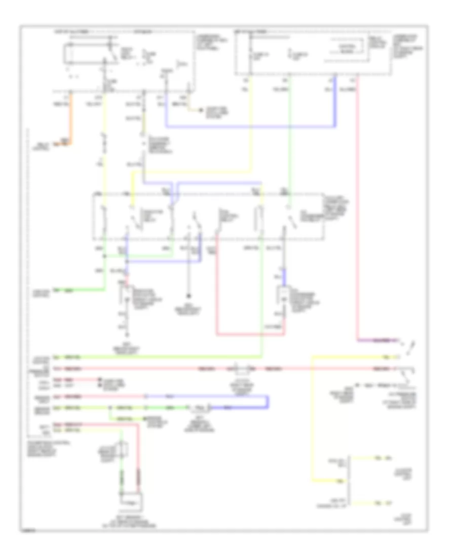
Cooling Fan Wiring Diagram for Honda Ridgeline RTL 2011
List of elements for Cooling Fan Wiring Diagram for Honda Ridgeline RTL 2011:
- (right rear of engine compt)
- A/c condenser fan motor (front middle of engine compt)
- A/c condenser fan relay
- A/c diode assembly (behind glove box)
- A/c pressure switch
- A/c pressure switch (at right side of engine compt)
- A20
- A21
- A37
- A48
- A49
- Auxiliary under-hood relay box (left rear of engine compt)
- B-can
- Block
- C14
- C16
- C32
- Can-h
- Can-l
- Canada: dx, vp
- Climate control unit
- Computer data lines system
- Control
- D11
- D16
- Ect sensor 1 (at rear of engine, on top of water passage)
- Ect sensor 2 (under left side of engine)
- Ect1
- Engine controls system
- Fan control relay
- Fuse 10a
- Fuse 19 30a
- Fuse 20 30a
- Fuse 7.5a
- G201 (behind right headlight)
- G202
- High fan control
- Hot at all times
- Hot in on
- Hvac control unit
- J/c c101 (right rear
- J/c c105 (rear of engine compt)
- Low fan control
- Micu
- N28
- Of engine compt)
- Pgm-fi main relay 1
- Powertrain control module (pcm) (right rear of engine compt)
- Radiator fan motor (front middle of engine compt)
- Radiator fan relay
- Red
- Relay control
- Relay control module
- Rts, rtl, ex-l
- Sensor ground
- Sensor input
- Sg2
- Under-dash fuse/relay box (at left kick panel)
- Under-hood fuse/relay box (at right rear of engine compt)
- Usa: rt;
 Čeština
 Dansk
Dansk Deutsch
 Ελληνικά
 English
 English
 Español
 Suomi
Suomi Français
 עברית
עברית Hrvatski
 Magyar
 Italiano
 日本語
日本語 한국어
한국어 Nederlands
 Polski
 Português
 Português
 Română
 Русский
 Slovenčina
 Slovenščina
 Svenska
 Türkçe
 中文 (中国)
 Français