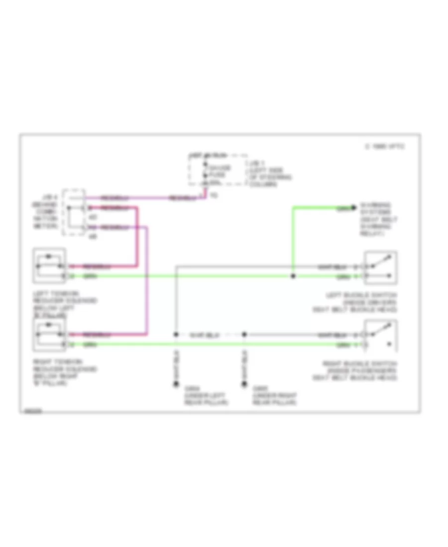
PASSIVE RESTRAINTS
Electric Tension Reducer Wiring Diagram for Lexus LS 400 1994
List of elements for Electric Tension Reducer Wiring Diagram for Lexus LS 400 1994:
- C 1995 vftc
- G904 (under left rear pillar)
- G905 (under right rear pillar)
- Gauge fuse 10a
- Hot in run
- J/b 1 (left side of steering column)
- J/b 4 (behind combi- nation meter)
- Left buckle switch (inside driver's seat belt buckle head)
- Left tension reducer solenoid (below left "b" pillar)
- Right buckle switch (inside passenger's seat belt buckle head)
- Right tension reducer solenoid (below right "b" pillar)
- Warning systems (seat belt warning relay)
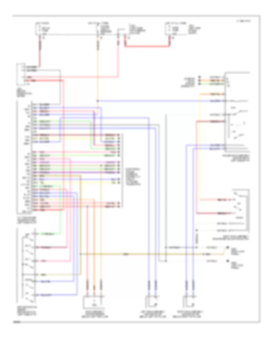
Power Shoulder Belt Anchorage Wiring Diagram for Lexus LS 400 1994
List of elements for Power Shoulder Belt Anchorage Wiring Diagram for Lexus LS 400 1994:
- (below right "b" pillar)
- 10a
- 15a
- A10
- A11
- A12
- Asw
- B. dw
- B. up
- B10
- B11
- B12
- B13
- B14
- B15
- B16
- B17
- B18
- Bem+
- Bem-
- Bes
- C 1995 vftc
- Dome fuse
- Down
- Driving position memory/ return switch (left side of i/p)
- Dsw
- Ecu-ig fuse
- Ecu. b
- Ecu. e
- Electronic power steering (power tilt circuit w/ power telescopic)
- G200 (left kick panel)
- G203 (right kick panel)
- Gnd
- Hot at all times
- Hot in run
- Interior lights system (rheostat)
- J/b 1 (left side of steering column)
- J/b 2 (left side of eng compt)
- J/b 4 (behind combination meter)
- Left shoulder belt anchor motor (below left "b" pillar)
- Mry
- Msw
- N0. 1
- N0. 2
- Pnk
- Power circuit breaker 30a
- Power shoulder belt anchor relay (left side of i/p)
- Red
- Right shoulder belt anchor motor
- Right shoulder belt anchorage adjusting switch
- Set
- Shoulder belt anchor sensor (below left "b"pillar)
- Tem+
- Tem-
- Tes
- Tilt and power telescopic ecu (left side of i/p)
- Tim+
- Tim-
- Tis
- U.w. sw

 Čeština
 Dansk
Dansk Deutsch
 Ελληνικά
 English
 English
 Español
 Suomi
Suomi Français
 עברית
עברית Hrvatski
 Magyar
 Italiano
 日本語
日本語 한국어
한국어 Nederlands
 Polski
 Português
 Português
 Română
 Русский
 Slovenčina
 Slovenščina
 Svenska
 Türkçe
 中文 (中国)